WO2013190858A1 - 流体圧縮機および摺動機構 - Google Patents
流体圧縮機および摺動機構 Download PDFInfo
- Publication number
- WO2013190858A1 WO2013190858A1 PCT/JP2013/050626 JP2013050626W WO2013190858A1 WO 2013190858 A1 WO2013190858 A1 WO 2013190858A1 JP 2013050626 W JP2013050626 W JP 2013050626W WO 2013190858 A1 WO2013190858 A1 WO 2013190858A1
- Authority
- WO
- WIPO (PCT)
- Prior art keywords
- sliding
- carboxyl group
- fluid compressor
- fluid
- sliding surface
- Prior art date
- Legal status (The legal status is an assumption and is not a legal conclusion. Google has not performed a legal analysis and makes no representation as to the accuracy of the status listed.)
- Ceased
Links
Images

Classifications
-
- F—MECHANICAL ENGINEERING; LIGHTING; HEATING; WEAPONS; BLASTING
- F04—POSITIVE - DISPLACEMENT MACHINES FOR LIQUIDS; PUMPS FOR LIQUIDS OR ELASTIC FLUIDS
- F04B—POSITIVE-DISPLACEMENT MACHINES FOR LIQUIDS; PUMPS
- F04B39/00—Component parts, details, or accessories, of pumps or pumping systems specially adapted for elastic fluids, not otherwise provided for in, or of interest apart from, groups F04B25/00 - F04B37/00
- F04B39/0005—Component parts, details, or accessories, of pumps or pumping systems specially adapted for elastic fluids, not otherwise provided for in, or of interest apart from, groups F04B25/00 - F04B37/00 adaptations of pistons
-
- F—MECHANICAL ENGINEERING; LIGHTING; HEATING; WEAPONS; BLASTING
- F05—INDEXING SCHEMES RELATING TO ENGINES OR PUMPS IN VARIOUS SUBCLASSES OF CLASSES F01-F04
- F05C—INDEXING SCHEME RELATING TO MATERIALS, MATERIAL PROPERTIES OR MATERIAL CHARACTERISTICS FOR MACHINES, ENGINES OR PUMPS OTHER THAN NON-POSITIVE-DISPLACEMENT MACHINES OR ENGINES
- F05C2225/00—Synthetic polymers, e.g. plastics; Rubber
- F05C2225/04—PTFE [PolyTetraFluorEthylene]
-
- F—MECHANICAL ENGINEERING; LIGHTING; HEATING; WEAPONS; BLASTING
- F05—INDEXING SCHEMES RELATING TO ENGINES OR PUMPS IN VARIOUS SUBCLASSES OF CLASSES F01-F04
- F05C—INDEXING SCHEME RELATING TO MATERIALS, MATERIAL PROPERTIES OR MATERIAL CHARACTERISTICS FOR MACHINES, ENGINES OR PUMPS OTHER THAN NON-POSITIVE-DISPLACEMENT MACHINES OR ENGINES
- F05C2253/00—Other material characteristics; Treatment of material
- F05C2253/12—Coating
Definitions
- the present invention relates to a fluid compressor and a sliding mechanism.
- a fluid compressor that compresses a fluid such as air is generally a metal cylinder, a metal piston that reciprocates in the cylinder to compress or expand the fluid, and the cylinder attached to the piston. And a piston ring, which is a sliding member that slides on the sliding surface.
- this piston ring is formed of a low friction, low abrasion property non-modified polytetrafluoroethylene (PTFE) as a base material mixed with a filler such as carbon fiber or graphite.
- PTFE polytetrafluoroethylene
- unmodified means that at least a part of fluorine constituting PTFE is selected from at least a carboxyl group (-COOH), an ether carboxyl group (-O-COOH) and an amino group (-NH 2 ). We say that we do not replace by one.
- FIG. 4 is explanatory drawing which represented typically the mode of the chemical bond with respect to the sliding face of non-modified PTFE molecule.
- the non-modified PTFE-based sliding material (not shown in FIG. 4) is a negatively charged fluorine atom (F ⁇ ) 42 in the non-modified PTFE molecule 41, A positively charged atom 44 in the sliding surface 43 and a chemical bond 45 via Coulomb attraction are formed to form a thin film (not shown) on the sliding surface 43.
- the sliding material (not shown) in FIG. 4 realizes low friction and low wear by sliding the surfaces of the thin film formed on the sliding surface 43 as sliding surfaces.
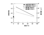
- FIG. 5 is a graph showing the influence of humidity on the coefficient of friction and the amount of wear of unmodified PTFE in vacuum and in the atmosphere.
- the horizontal axis shows humidity (%)
- the right vertical axis shows the friction coefficient
- the left vertical axis shows the amount of wear (mm 3 ).
- unmodified PTFE is good because the coefficient of friction and the amount of wear are low when in vacuum.
- the humidity is high
- unmodified PTFE has a low coefficient of friction and a low amount of wear
- the coefficient of friction and a high amount of wear will be high, which is not good.
- non-modified PTFE molecules 41 may be formed by the electrically neutral gas.
- the coulomb attraction between the positively charged atoms 44 in the sliding surface 43 is shielded, and the amount of non-modified PTFE deposited is significantly reduced.
- a mating material (sliding surface 43) harder than the non-modified PTFE-based sliding material comes into direct contact with the surface of the sliding material to cause friction. Therefore, there is a problem that the wear of the sliding material is increased by 10 times or more due to the cutting action or the like, and the durability of the sliding material is lowered.
- Patent Document 1 discloses an invention relating to a fluid compressor provided with a compression chamber for compressing a fluid. Specifically, according to Patent Document 1, it is possible to improve the wear resistance of a sliding material applicable to a fluid compression machine such as a reciprocating compressor or a reciprocating expander, and accordingly, it is possible to use The exchange life can be extended, and further, the abrasion resistance can be further improved in any of the air and an inert gas atmosphere such as nitrogen gas, and in particular, the inert gas such as nitrogen gas can be particularly improved.
- PTFE When used in an atmosphere, PTFE is used as a base material and copper oxide is contained in part of the filler material for the purpose of providing a sliding material and a fluid compression machine capable of preventing abnormal wear when used in an atmosphere And a fluid compressor comprising the same.
- the sliding material is hardened by containing copper oxide in PTFE to improve the wear resistance in an inert gas atmosphere such as nitrogen gas. Therefore, although the fluid compressor to which the invention described in Patent Document 1 is applied has gained popularity in the market, further improvement in the abrasion resistance has been demanded by the industry.
- the present invention has been made in view of such circumstances, and as a fluid, a fluid compressor and a slide provided with a slide material that does not easily wear even when an electrically neutral gas is compressed
- the task is to provide a mechanism.
- the present application includes a plurality of means for solving the above problems, and an example thereof is a fluid compressor provided with a compression chamber for compressing a fluid, the compression chamber having a sliding surface, and the sliding surface. And a sliding member that slides on a surface, wherein the sliding member is formed using modified polytetrafluoroethylene.
- a sliding mechanism comprising: a sliding surface; and a sliding material sliding on the sliding surface, wherein the sliding material is formed using modified polytetrafluoroethylene. is there.
- FIG. 1 It is a sectional view explaining a fluid compressor concerning one embodiment of the present invention. It is the A section enlarged view of FIG. It is explanatory drawing which represented typically the mode of the chemical bond with respect to the sliding face of a modified
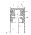
- FIG. 1 is a cross-sectional view for explaining a fluid compressor according to an embodiment of the present invention.
- a fluid compressor 1 according to an embodiment of the present invention includes a compression chamber 2 for compressing a fluid.
- the electrically neutral gas can include, for example, dry air, and can also include, for example, a gas containing at least one of nitrogen, argon, and helium.
- the gas containing at least one of nitrogen, argon and helium is preferably an inert gas mixed with one or more selected from these. That is, such an inert gas may be a high purity gas containing one selected from those described above with high purity, or a mixed gas in which two or more are mixed in an arbitrary ratio. Good.
- the above-mentioned high purity gas is generally called nitrogen gas, argon gas, helium gas or the like depending on the elements contained.
- “dried” means that the water content in the gas is 5 ppm or less.
- “high purity” means, for example, one having a content ratio (purity) of 99.9995% or more, and the inclusion of unavoidable impurity gases such as air is permitted if the amount is contained to an extent that can not be unavoidably contained Ru.
- a mixed gas as long as it is electrically neutral, it may contain components other than the above-described elements.
- air containing humidity eg, about 20 to 90% humidity
- oxygen gas oxygen gas
- hydrogen gas can be compressed as a fluid.
- the above-mentioned compression chamber 2 is composed of a cylinder 21 and a piston 22 reciprocating in the cylinder 21.
- a piston ring 23 is attached above the piston 22, and a rider ring 24 for supporting the linear motion of the piston 22 is attached at a position below the piston ring 23.
- the piston 22 is connected to the connecting rod 26 by a piston pin 25.
- the connecting rod 26 is connected to the motor via a shaft member or the like (not shown). Therefore, the piston 22 can be reciprocated within the cylinder 21 by driving the motor.
- Examples of such a fluid compressor 1 include reciprocating compressors such as an oil-free reciprocating compressor and an oil-feeding reciprocating compressor.
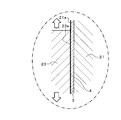
- FIG. 2 is an enlarged view of a portion A of FIG.
- the piston 22 having the piston ring 23 attached thereto reciprocates in the cylinder 21. Therefore, as shown in FIG. 2, the inner surface of the cylinder 21 corresponds to the sliding surface 21a, and the piston ring 23 corresponds to the sliding member 23a. That is, the compression chamber 2 includes the sliding surface 21 a and the sliding member 23 a that slides on the sliding surface 21 a. And in this invention, this sliding material 23a is formed using modified PTFE.
- modification means that at least a part of fluorine constituting PTFE is at least one selected from a carboxyl group (-COOH), an ether carboxyl group (-O-COOH) and an amino group (-NH 2 ) It is the one replaced by.
- a modified PTFE the compound represented by following formula (1) can be mentioned.
- i, j and k are integers and satisfy the relationship of 0 ⁇ k ⁇ i + j
- X1, X2 and X3 are selected from fluorine, carboxyl group, ether carboxyl group and amino group
- at least one of X1, X2 and X3 is a carboxyl group, an ether carboxyl group or an amino group.
- the carboxyl group, the ether carboxyl group and the amino group are preferably provided on the main chain or at the main chain terminal of the PTFE molecule.
- the PTFE molecule has a branched structure, it is also preferable to provide these functional groups at the side chain or side chain end.
- the sliding member 23a can be formed partially or entirely of the above-described modified PTFE.
- a filler such as copper oxide, graphite, molybdenum disulfide or the like may be contained at an appropriate content as another part forming the sliding material 23a. Can. In this way, it is possible to improve the strength of the substrate and to improve the slidability, that is, to reduce friction and wear.
- the whole of the sliding material 23a is formed of modified PTFE, it means that the sliding material 23a is formed of only modified PTFE, literally, and the above-mentioned filler is not used.
- modified PTFE When such modified PTFE is used, it has self-lubricating properties like non-modified PTFE, and it is possible to achieve low friction and low wear.
- the modified PTFE adheres to the surface of the mating material (sliding surface 21a) to form the thin film 3, and the thin film 3 and the surface where the sliding material 23a comes in contact form the sliding surface 4 and slide on each other. It is obtained by
- the thin film 3 in the present embodiment is formed using the above-described modified PTFE, a sliding material formed using non-modified PTFE even in the case of compressing an electrically neutral gas. It can be less likely to wear as compared with.
- the effect is that the chemical bond between the carbon atom in the modified PTFE molecule and the oxygen atom in the carboxyl group or the ether carboxyl group is more polarized than the chemical bond between the carbon atom in the unmodified PTFE molecule and the fluorine atom. Is obtained because it is large.
- the larger the charge amount of the PTFE molecules the larger the Coulomb attraction force with the atoms of the sliding surface 21a supporting the bonding of the PTFE molecules, so the chemical bonding to the sliding surface 21a becomes stronger.
- the chemical bond between the carbon atom in the modified PTFE molecule and the nitrogen atom in the amino group since the chemical bond by these is larger in polarization than the chemical bond with the carbon atom in the unmodified PTFE molecule and the fluorine atom, the Coulomb attraction between the atoms on the sliding surface 21a becomes larger, and The chemical bond to the moving surface 21a is strengthened.
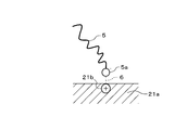
- FIG. 3 shows a diagram for explaining the contents.
- FIG. 3 is an explanatory view schematically showing the state of chemical bonding (chemical adsorption) to the sliding surface of the modified PTFE molecule.
- the molecule 5a containing an oxygen atom in the carboxyl group or ether carboxyl group contained in the modified PTFE molecule 5 or a nitrogen atom in the amino group is fluorine in the unmodified PTFE molecule 41 (see FIG. 4).
- the slide surface 21a is negatively charged with a charge amount larger than that of the atom 42 (see FIG. 4), and forms a strong chemical bond 6 via the Coulomb attraction with the positively charged atom 21b in the slide surface 21a.
- a thin film 3 (see FIG. 2) is formed thereon.
- the sliding material 23a formed by using the modified PTFE can adhere the adhesion amount of the modified PTFE to the sliding surface 21a even when the electrically neutral gas is compressed as a fluid. You can do more. As a result, the sliding member 23a is less likely to be worn even when electrically neutral gas is compressed as a fluid.
- the modified PTFE is one in which at least a part of the fluorine constituting the PTFE is substituted with a carboxyl group
- the hydrogen atom in the carboxyl group is positively charged, so the negatively charged in the sliding surface 21a is negatively charged.
- Such modified PTFE can be produced, for example, by performing atmospheric pressure plasma irradiation on unmodified PTFE.
- the atmospheric pressure plasma irradiation may be performed, for example, using helium as a carrier gas and water as a reaction gas under an atmosphere pressure of 10 2 to 10 3 Pa and a high frequency electric field of 300 W applied.
- the modified PTFE adheres to the sliding surface 21 a from the sliding material 23 a to the sliding surface 21 a to form the thin film 3.
- the thickness of the thin film 3 is preferably 1 to 100 nm. When the thickness of the thin film 3 is in this range, it is possible to more reliably provide the fluid compressor 1 that is resistant to wear even when compressing electrically neutral gas as a fluid.
- the thickness of the thin film 3 is not limited to this range.
- the thickness of the thin film 3 may be less than 1 nm or more than 100 nm.
- the thickness of the thin film 3 is arbitrary.
- the member constituting the compression chamber 2, for example, the cylinder 21 is preferably made of a metal material, and its surface, that is, the sliding surface 21a is more preferably coated with an oxide obtained by oxidizing the metal material.
- covering with an oxide means forming an oxide film.
- the surface of the metal material (sliding surface 21a) is coated with the oxide, the surface property becomes porous. Therefore, the modified PTFE can be firmly attached so as to fill the porous recess. Further, since the surface area of the sliding surface 21a is increased by the porous unevenness, the number of positively or negatively charged atoms 21b (see FIG. 3) in the sliding surface 21a is also increased.
- the modified PTFE molecule 5 (see FIG. 3) can be attached more firmly to the sliding surface 21a (see FIG. 3). ).
- the sliding member 23a can be made more difficult to wear.
- the corrosion resistance can be improved.
- an aluminum alloy is preferable, for example, pure aluminum, pure titanium, a titanium alloy, a steel material, etc. can also be used.
- a natural oxide film is usually formed on the surface, but it is more preferable to perform anodizing treatment or the like. In this way, a passive film is obtained, the surface quality is further porous, and the adhesion of the modified PTFE molecule 5 to the sliding surface 21a can be made stronger.
- the passivation film is obtained as described above, the corrosion resistance is improved.
- the thin film 3 of the modified PTFE described above is formed in advance on the sliding surface 21a.
- the sliding surface 21a is anodized, it is also preferable to include the above-mentioned modified PTFE in the porous holes formed on the surface. In this way, it is possible to reliably form the modified PTFE thin film 3 with a thickness of 1 to 100 nm.
- the fluid compressor 1 described above can be provided with the sliding member 23a that is not easily worn even when compressing an electrically neutral gas as the fluid. Therefore, durability of sliding materials, such as a piston ring, improves, and it can achieve lifetime improvement.
- the present embodiment is formed of modified PTFE or non-denatured PTFE capable of adhering to the sliding surface of the anodized aluminum alloy in air and in an electrically neutral dry gas (inert gas).
- the sliding material was examined.
- a sliding material of 4 nm in thickness formed of modified PTFE or unmodified PTFE in which a part of fluorine in PTFE molecules is substituted by a substituent shown in Table 1 is the surface of an aluminum alloy on which anodizing treatment is performed. It implemented to the interface model in contact with the imitation alumina layer.
- the operating environment of the fluid compressor was simulated, and air, nitrogen, argon, and helium were set as the gas molecules.
- the friction condition is obtained by giving a vertical pressure of 5 ⁇ 10 8 Pa and a horizontal sliding velocity of 10 m / s to the alumina layer, temperature 300 K, integration time 2 ⁇ 10 ⁇ 15 s, calculation step 5 ⁇ 10 5 Adopted.
- the adhesion volume (adhesion amount (nm 3 )) of the sliding material to the alumina layer was determined from the displacement of all the molecules contained in the sliding material obtained as a result of the MD simulation.
- the modified PTFE according to 1 to 5 can provide a sliding material that is resistant to abrasion even when electrically neutral gas (fluid) is compressed. Therefore, it was strongly suggested that in the fluid compressor provided with the sliding material formed using these modified PTFEs, the durability of the sliding material such as the piston ring can be improved and the life can be extended. .
- the content of this invention was demonstrated in detail by the form which implements invention, this invention is not limited to above-mentioned content, A various modified example is included.
- the piston ring 23 was mentioned and demonstrated as an example of the sliding material 23a, the rider ring 24 grade
- appropriate sealing materials, bearings and the like can also be formed using the modified PTFE described in the present specification.
- the modified PTFE described in the present specification can be applied to the entire sliding mechanism provided with a sliding surface and a sliding member sliding on the sliding surface. That is, the sliding material in the sliding mechanism can be formed using the modified PTFE described in the present specification. In this way, the durability of the sliding member in a machine (sliding mechanism) used under an electrically neutral gas atmosphere as well as a fluid compressor can be improved, and a long life can be achieved.
- the above-described embodiment is described in detail in order to explain the present invention in an easy-to-understand manner, and is not necessarily limited to one having all the described configurations. Further, part of the configuration of one embodiment can be replaced with the configuration of another embodiment, and the configuration of another embodiment can be added to the configuration of one embodiment. Moreover, it is possible to add, delete, and replace other configurations for part of the configurations of the respective embodiments.
Landscapes
- Engineering & Computer Science (AREA)
- Mechanical Engineering (AREA)
- General Engineering & Computer Science (AREA)
- Compressor (AREA)
- Compressors, Vaccum Pumps And Other Relevant Systems (AREA)
Abstract
流体として、電気的に中性なガスを圧縮する場合であっても摩耗し難い摺動材を備えた流体圧縮機を提供する。流体を圧縮する圧縮室(2)を備えた流体圧縮機(1)であり、前記圧縮室(2)は、摺動面(21a)と、前記摺動面(21a)と摺動する摺動材(ピストンリング(23))と、を備え、前記摺動材が、変性ポリテトラフルオロエチレンを用いて形成されていることを特徴とする。変性ポリテトラフルオロエチレンは、ポリテトラフルオロエチレンを構成するフッ素の少なくとも一部をカルボキシル基、エーテルカルボキシル基およびアミノ基から選択される少なくとも一つで置換されたものであるのが好ましい。
Description
本発明は、流体圧縮機および摺動機構に関する。
空気などの流体を圧縮する流体圧縮機は、一般的に、金属製のシリンダと、このシリンダ内を往復動して流体を圧縮または膨張する金属製のピストンと、このピストンに取り付けられて前記シリンダの摺動面と摺動する摺動材であるピストンリングと、を備えている。
多くの場合、このピストンリングは、低摩擦性、低摩耗性を有する未変性ポリテトラフルオロエチレン(PTFE)を基材とし、これに炭素繊維やグラファイトなどの充填材を混合したもので形成されている。なお、本発明において、未変性とは、PTFEを構成するフッ素の少なくとも一部をカルボキシル基(-COOH)、エーテルカルボキシル基(-O-COOH)およびアミノ基(-NH2)から選択される少なくとも一つで置換していないことをいう。
未変性PTFEを基材とする摺動材の低摩擦化と低摩耗化は、図4を参照して説明するようにして具現される。なお、図4は、未変性PTFE分子の摺動面に対する化学結合の様子を模式的に表した説明図である。
図4に示すように、未変性PTFEを基材とする摺動材は(図4において図示せず)、未変性PTFE分子41中にある、負に帯電したフッ素原子(F-)42が、摺動面43の中の正に帯電した原子44とクーロン引力を介した化学結合45を形成して摺動面43上に図示しない薄膜を形成する。図4において図示しない摺動材は、摺動面43上に形成されたこの薄膜の表面がすべり面となって互いに摺動することで低摩擦化と低摩耗化を具現している。
図4に示すように、未変性PTFEを基材とする摺動材は(図4において図示せず)、未変性PTFE分子41中にある、負に帯電したフッ素原子(F-)42が、摺動面43の中の正に帯電した原子44とクーロン引力を介した化学結合45を形成して摺動面43上に図示しない薄膜を形成する。図4において図示しない摺動材は、摺動面43上に形成されたこの薄膜の表面がすべり面となって互いに摺動することで低摩擦化と低摩耗化を具現している。
図5は、湿度が、真空中および大気中における未変性PTFEの摩擦係数と摩耗量に与える影響を表したグラフである。同図中、横軸は湿度(%)を示し、右縦軸は摩擦係数を示し、左縦軸は摩耗量(mm3)を示す。
図5に示すように、未変性PTFEは、真空中であれば摩擦係数と摩耗量が低く良好である。一方、大気中においては、湿度が高ければ、未変性PTFEは、摩擦係数と摩耗量が低く良好であるのに対し、湿度が低くなると摩擦係数と摩耗量が高くなり、良好でなくなる。
図5に示すように、未変性PTFEは、真空中であれば摩擦係数と摩耗量が低く良好である。一方、大気中においては、湿度が高ければ、未変性PTFEは、摩擦係数と摩耗量が低く良好であるのに対し、湿度が低くなると摩擦係数と摩耗量が高くなり、良好でなくなる。
このような理由から、流体として、湿気を含んだ空気を圧縮する場合、未変性PTFEを基材とする摺動材に問題が生じることはなかった。
しかし、流体として、例えば、乾燥した空気、窒素ガス、アルゴンガス、ヘリウムガスなどの電気的に中性なガスを圧縮する場合、当該電気的に中性なガスによって、未変性PTFE分子41と、摺動面43の中の正に帯電した原子44との間のクーロン引力が遮蔽され、未変性PTFEの付着量が著しく減少してしまう。このような状況になると、未変性PTFEを基材とする摺動材よりも硬質な相手材(摺動面43)が摺動材の表面を直接接触して摩擦するようになる。そのため、切削作用などにより摺動材の摩耗が10倍以上増加し、摺動材の耐久性が低下するという問題があった。
しかし、流体として、例えば、乾燥した空気、窒素ガス、アルゴンガス、ヘリウムガスなどの電気的に中性なガスを圧縮する場合、当該電気的に中性なガスによって、未変性PTFE分子41と、摺動面43の中の正に帯電した原子44との間のクーロン引力が遮蔽され、未変性PTFEの付着量が著しく減少してしまう。このような状況になると、未変性PTFEを基材とする摺動材よりも硬質な相手材(摺動面43)が摺動材の表面を直接接触して摩擦するようになる。そのため、切削作用などにより摺動材の摩耗が10倍以上増加し、摺動材の耐久性が低下するという問題があった。
このような問題を解決すべく、例えば、特許文献1には、流体を圧縮する圧縮室を備えた流体圧縮機に関する発明が開示されている。
具体的には、この特許文献1には、往復動圧縮機や往復動膨張機等の流体圧縮機械に適用可能な摺動材の耐摩耗性を向上させることができ、したがって、摺動材の交換寿命を長くすることができ、さらには、空気中、窒素ガス等の不活性ガス雰囲気中のいずれにおいても従来以上に耐摩耗性を向上させることができ、特に、窒素ガス等の不活性ガス雰囲気中にて用いた場合においては異常摩耗を防止することができる摺動材及び流体圧縮機械を提供することを目的として、PTFEを基材とし、充填材の一部に酸化銅を含有してなる摺動材と、これを備えてなる流体圧縮機が記載されている。
具体的には、この特許文献1には、往復動圧縮機や往復動膨張機等の流体圧縮機械に適用可能な摺動材の耐摩耗性を向上させることができ、したがって、摺動材の交換寿命を長くすることができ、さらには、空気中、窒素ガス等の不活性ガス雰囲気中のいずれにおいても従来以上に耐摩耗性を向上させることができ、特に、窒素ガス等の不活性ガス雰囲気中にて用いた場合においては異常摩耗を防止することができる摺動材及び流体圧縮機械を提供することを目的として、PTFEを基材とし、充填材の一部に酸化銅を含有してなる摺動材と、これを備えてなる流体圧縮機が記載されている。
前記特許文献1に記載の発明では、PTFEに酸化銅を含有させることで摺動材を硬質化し、窒素ガス等の不活性ガス雰囲気中での耐摩耗性の改善を図っている。そのため、特許文献1に記載の発明を適用した流体圧縮機は、市場で好評を博するに至ったが、産業界から、さらなる耐摩耗性の改善が要望されるようになった。
本発明は、このような事情に鑑みてなされたものであり、流体として、電気的に中性なガスを圧縮する場合であっても摩耗し難い摺動材を備えた流体圧縮機および摺動機構を提供することを課題とする。
前記課題を解決するために、例えば特許請求の範囲に記載の構成を採用する。
本願は前記課題を解決する手段を複数含んでいるが、その一例を挙げるならば、流体を圧縮する圧縮室を備えた流体圧縮機であり、前記圧縮室は、摺動面と、前記摺動面と摺動する摺動材と、を備え、前記摺動材が、変性ポリテトラフルオロエチレンを用いて形成されていることを特徴とする流体圧縮機である。
また、摺動面と、前記摺動面と摺動する摺動材と、を備え、前記摺動材が、変性ポリテトラフルオロエチレンを用いて形成されていることを特徴とする摺動機構である。
本願は前記課題を解決する手段を複数含んでいるが、その一例を挙げるならば、流体を圧縮する圧縮室を備えた流体圧縮機であり、前記圧縮室は、摺動面と、前記摺動面と摺動する摺動材と、を備え、前記摺動材が、変性ポリテトラフルオロエチレンを用いて形成されていることを特徴とする流体圧縮機である。
また、摺動面と、前記摺動面と摺動する摺動材と、を備え、前記摺動材が、変性ポリテトラフルオロエチレンを用いて形成されていることを特徴とする摺動機構である。
本発明によれば、流体として、電気的に中性なガスを圧縮する場合であっても摩耗し難い摺動材を備えた流体圧縮機および摺動機構を提供することができる。
以下、適宜図面を参照して、本発明を実施するための形態(実施形態)について詳細に説明する。
図1は、本発明の一実施形態に係る流体圧縮機を説明する断面図である。
図1に示すように、本発明の一実施形態に係る流体圧縮機1は、流体を圧縮する圧縮室2を備えている。
図1は、本発明の一実施形態に係る流体圧縮機を説明する断面図である。
図1に示すように、本発明の一実施形態に係る流体圧縮機1は、流体を圧縮する圧縮室2を備えている。
ここで、流体としては、電気的に中性なガスを挙げることができる。電気的に中性なガスとしては、例えば、乾燥した空気を挙げることができ、また、例えば、窒素、アルゴンおよびヘリウムのうちの少なくとも1種を含有してなるガスを挙げることができる。窒素、アルゴンおよびヘリウムのうちの少なくとも1種を含有してなるガスは、これらから選択される1種または2種以上を混合した不活性ガスであるのが好ましい。つまり、かかる不活性ガスは、前記したもののうちから選択される1種を高い純度で含有する高純度ガスであってもよいし、2種以上を任意の比率で混合した混合ガスであってもよい。なお、前記した高純度ガスは、含有される元素に応じて、一般的に、窒素ガス、アルゴンガス、ヘリウムガスなどと呼ばれている。ここで、「乾燥した」とは、ガス中の水分量が5ppm以下であることをいう。また、「高純度」とは、例えば含有比率(純度)が99.9995%以上であるものをいい、不可避的に含有される程度の量であれば空気等の不可避不純物ガスの含有は許容される。混合ガスである場合は、電気的に中性であれば、前記した元素以外の成分を含有していてもよい。もちろん、流体として湿度を含む空気(例えば、湿度約20~90%)や酸素ガス、水素ガスを圧縮できることはいうまでもない。
図1に示すとおり、前記した圧縮室2は、シリンダ21と、このシリンダ21内を往復動するピストン22で構成されている。ピストン22の上方には、ピストンリング23が取り付けられており、ピストンリング23よりも下の位置に、ピストン22の直線運動を支持するためのライダーリング24が取り付けられている。ピストン22は、ピストンピン25により連結棒26と連結され、連結棒26は図示しない軸部材等を介して原動機と連結されている。そのため、原動機を駆動させることによってピストン22をシリンダ21内で往復動させることができる。このような流体圧縮機1としては、例えば、無給油式往復動圧縮機や給油式往復動圧縮機などの往復動圧縮機を挙げることができる。
図2は、図1のA部拡大図である。前記したように、流体圧縮機1は、シリンダ21内をピストンリング23が取り付けられたピストン22が往復動する。したがって、図2に示すように、シリンダ21の内表面が摺動面21aに相当し、ピストンリング23が摺動材23aに相当する。つまり、圧縮室2は、摺動面21aと、摺動面21aと摺動する摺動材23aと、を備えている。そして、本発明においては、この摺動材23aを、変性PTFEを用いて形成している。なお、本発明において変性とは、PTFEを構成するフッ素の少なくとも一部をカルボキシル基(-COOH)、エーテルカルボキシル基(-O-COOH)およびアミノ基(-NH2)から選択される少なくとも一つで置換したものをいう。変性PTFEとしては、具体的には、下記式(1)で表される化合物を挙げることができる。

ただし、前記式(1)中、i、j、kは、整数であり、かつ0≦k<i+jの関係を満たし、X1、X2、X3はフッ素、カルボキシル基、エーテルカルボキシル基およびアミノ基から選択される少なくとも一つであり、X1、X2、X3の少なくとも1つはカルボキシル基、エーテルカルボキシル基またはアミノ基である。カルボキシル基、エーテルカルボキシル基およびアミノ基は、PTFE分子の主鎖上または主鎖末端に設けるのが好ましい。PTFE分子が枝分かれ構造をもつ場合には、これらの官能基を側鎖または側鎖末端に設けるのも好ましい。
摺動材23aは、一部または全部を前記した変性PTFEで形成することができる。摺動材23aの一部を変性PTFEで形成する場合、摺動材23aを形成する他の部分として、例えば、酸化銅、黒鉛、二硫化モリブデンなどの充填剤を適宜の含有量で含有させることができる。このようにすると、基材の強度を向上させたり、摺動性の向上、すなわち低摩擦化および低摩耗化を図ったりすることができる。一方、摺動材23aの全部を変性PTFEで形成する場合とは、文字通り変性PTFEのみで摺動材23aを形成し、前記した充填剤を用いないことをいう。
このような変性PTFEを用いると、未変性PTFEと同様に自己潤滑性を有し、低摩擦化と低摩耗化を図ることができる。
かかる作用は、変性PTFEが相手材の表面(摺動面21a)に付着して薄膜3を形成し、この薄膜3と、摺動材23aが接触する面がすべり面4となって互いに摺動することによって得られる。
かかる作用は、変性PTFEが相手材の表面(摺動面21a)に付着して薄膜3を形成し、この薄膜3と、摺動材23aが接触する面がすべり面4となって互いに摺動することによって得られる。
また、本実施形態における薄膜3は、前記した変性PTFEを用いて形成されているので、電気的に中性なガスを圧縮する場合であっても、未変性PTFEを用いて形成した摺動材と比較してより摩耗し難いものとすることができる。かかる効果は、変性PTFE分子中における炭素原子と、カルボキシル基若しくはエーテルカルボキシル基中の酸素原子との化学結合の方が、未変性PTFE分子中における炭素原子と、フッ素原子との化学結合よりも分極が大きいために得られる。つまり、PTFE分子の電荷量が大きいほどPTFE分子の結合を支持する摺動面21aの原子との間のクーロン引力が大きくなるため、摺動面21aに対する化学結合が強固になる。これは、変性PTFE分子中における炭素原子と、アミノ基中の窒素原子との化学結合についても同様である。つまり、これらによる化学結合の方が、未変性PTFE分子中における炭素原子と、フッ素原子との化学結合よりも分極が大きいため、摺動面21aの原子との間のクーロン引力が大きくなり、摺動面21aに対する化学結合が強固になる。
図3に前記内容を説明する図を示した。図3は、変性PTFE分子の摺動面に対する化学結合(化学吸着)の様子を模式的に表した説明図である。図3に示すように、変性PTFE分子5に含まれるカルボキシル基若しくはエーテルカルボキシル基中の酸素原子またはアミノ基中の窒素原子を含む分子5aが、未変性PTFE分子41(図4参照)中のフッ素原子42(図4参照)よりも大きな荷電量をもって負に帯電し、摺動面21aの中の正に帯電した原子21bとクーロン引力を介した強固な化学結合6を形成して摺動面21a上に薄膜3(図2参照)を形成する。
このような作用により、変性PTFEを用いて形成される摺動材23aは、流体として電気的に中性なガスを圧縮する場合であっても、摺動面21aへの変性PTFEの付着量を多くすることができる。その結果、摺動材23aは、流体として電気的に中性なガスを圧縮する場合であっても摩耗し難くなっている。
また、変性PTFEが、PTFEを構成するフッ素の少なくとも一部をカルボキシル基で置換したものである場合は、カルボキシル基中の水素原子が正に帯電するため、摺動面21aの中の負に帯電した原子とも化学結合することができる。そのため、摺動面21aにより強固に化学結合した薄膜3(図2参照)を形成することができる。したがって、そのような変性PTFEを用いて形成される摺動材23aは、流体として電気的に中性なガスを圧縮する場合であってもより摩耗し難いものとなる。
このような変性PTFEは、例えば、未変性PTFEに対して大気圧プラズマ照射を行うことにより製造することができる。大気圧プラズマ照射は、例えば、キャリヤガスとしてヘリウム、反応ガスとして水を用い、102~103Paの雰囲気圧力、300Wの高周波電界を印加した条件で処理すればよい。
図2を参照して説明したように、摺動面21aには摺動材23aから摺動面21aに変性PTFEが付着して薄膜3が形成される。この薄膜3の厚さは、1~100nmとするのが好ましい。薄膜3の厚さがこの範囲にあると、流体として電気的に中性なガスを圧縮する場合であっても摩耗し難い流体圧縮機1をより確実に提供することができる。なお、薄膜3の厚さはこの範囲に限定されるものではない。薄膜3の厚さは1nm未満としてもよいし、100nmを超えてもよい。薄膜3の厚さは任意である。
圧縮室2を構成する部材、例えばシリンダ21は、金属材料で構成するのが好ましく、その表面、すなわち、摺動面21aは当該金属材料を酸化させた酸化物で被覆するのがより好ましい。なお、酸化物で被覆するとは、酸化皮膜を形成することをいう。金属材料の表面(摺動面21a)が酸化物で被覆されると、その表面性状は多孔質となる。そのため、多孔質の凹部を埋めるように変性PTFEが強固に付着できる。また、多孔質の凹凸により摺動面21aの表面積が増えるので、摺動面21aの中の正または負に帯電した原子21b(図3参照)の数も多くなり、変性PTFE分子5中の負または正に分極した分子がこれと化学結合し易くなってその数も多くなることから、変性PTFE分子5(図3参照)がより強固に摺動面21aに付着できるようになる(図3参照)。その結果、電気的に中性なガスを圧縮する場合であっても、摺動材23aをよりさらに摩耗し難くすることができる。また、摺動面21aは酸化物で被覆すると、耐食性を向上させることができる。
金属材料としては、例えば、アルミニウム合金が好ましいが、純アルミニウム、純チタン、チタン合金、鉄鋼材などを用いることもできる。
金属材料としてアルミニウム合金を用いた場合、その表面には通常、自然酸化皮膜が形成されているが、陽極酸化処理などを施すのがより好ましい。このようにすると不動態皮膜が得られ、表面性状がさらに多孔質となり、変性PTFE分子5の摺動面21aへの付着をより強固なものとすることができる。また、前記したように不動態皮膜が得られるので、耐食性が向上する。
金属材料としてアルミニウム合金を用いた場合、その表面には通常、自然酸化皮膜が形成されているが、陽極酸化処理などを施すのがより好ましい。このようにすると不動態皮膜が得られ、表面性状がさらに多孔質となり、変性PTFE分子5の摺動面21aへの付着をより強固なものとすることができる。また、前記したように不動態皮膜が得られるので、耐食性が向上する。
なお、摺動面21aに前記した変性PTFEの薄膜3を予め形成しておくのも好ましい。また、摺動面21aを陽極酸化処理した場合、表面に形成された多孔質の孔に前記した変性PTFEを含ませておくのも好ましい。これらのようにすると、変性PTFEの薄膜3を1~100nmの厚さで確実に形成することが可能となる。
これらの態様は、摺動面21aに変性PTFEを塗布したり(塗布法)、少なくとも摺動面21aが変性PTFE分散液内に浸かるようにしたり(浸漬法)することで具現することができる。
これらの態様は、摺動面21aに変性PTFEを塗布したり(塗布法)、少なくとも摺動面21aが変性PTFE分散液内に浸かるようにしたり(浸漬法)することで具現することができる。
以上に説明した流体圧縮機1は、流体として、電気的に中性なガスを圧縮する場合であっても摩耗し難い摺動材23aを備えることができる。そのため、ピストンリングなどの摺動材の耐久性が向上し、長寿命化を図ることができる。
次に、本発明所望の効果を奏する実施例により本発明について、より具体的に説明する。
本実施例では、大気中および電気的に中性な乾燥したガス(不活性ガス)中において、陽極酸化処理されたアルミニウム合金の摺動面に付着が可能な変性PTFEまたは未変性PTFEで形成した摺動材について検討した。
〔1〕分子動力学シミュレーション
なお、摺動材の分子の移着は摩擦中に起こるミクロスケール現象であり、実験的に摩擦中のその場解析を実施することは困難である。そのため、本実施例では、摺動材の付着量を調べるために分子動力学(MD)シミュレーションを行った。
なお、摺動材の分子の移着は摩擦中に起こるミクロスケール現象であり、実験的に摩擦中のその場解析を実施することは困難である。そのため、本実施例では、摺動材の付着量を調べるために分子動力学(MD)シミュレーションを行った。
MDシミュレーションは、PTFE分子中のフッ素の一部を表1に示す置換基で置換した変性PTFEまたは未変性PTFEで形成した厚さ4nmの摺動材が、陽極酸化処理されたアルミニウム合金の表面を模したアルミナ層に接触した界面モデルに対して実施した。
また、前記薄膜とアルミナ層との間にガス分子を介在させることで流体圧縮機の動作環境を模擬し、ガス分子として大気、窒素、アルゴン、ヘリウムを設定した。
MDシミュレーションでは、アルミナ層に対する垂直圧力5×10⁸Pa、水平方向のすべり速度10m/sを与えることで摩擦条件とし、温度300K、積分時間2×10-15s、計算ステップ5×105を採用した。
そして、MDシミュレーションの結果として得られる、摺動材中に含まれる全ての分子の変位から、アルミナ層に対する摺動材の付着体積(付着量(nm3))を求めた。
また、前記薄膜とアルミナ層との間にガス分子を介在させることで流体圧縮機の動作環境を模擬し、ガス分子として大気、窒素、アルゴン、ヘリウムを設定した。
MDシミュレーションでは、アルミナ層に対する垂直圧力5×10⁸Pa、水平方向のすべり速度10m/sを与えることで摩擦条件とし、温度300K、積分時間2×10-15s、計算ステップ5×105を採用した。
そして、MDシミュレーションの結果として得られる、摺動材中に含まれる全ての分子の変位から、アルミナ層に対する摺動材の付着体積(付着量(nm3))を求めた。
表1のNo.1~6に、変性PTFEまたは未変性PTFEの条件と、MDシミュレーションによって算出される大気中(湿度50%)、窒素ガス中、アルゴンガス中またはヘリウムガス中における摺動材からアルミナ層への付着量と、大気中における未変性PTFE(No.6)の付着量を基準値とした各条件における付着量の増減率(%)を記載した。
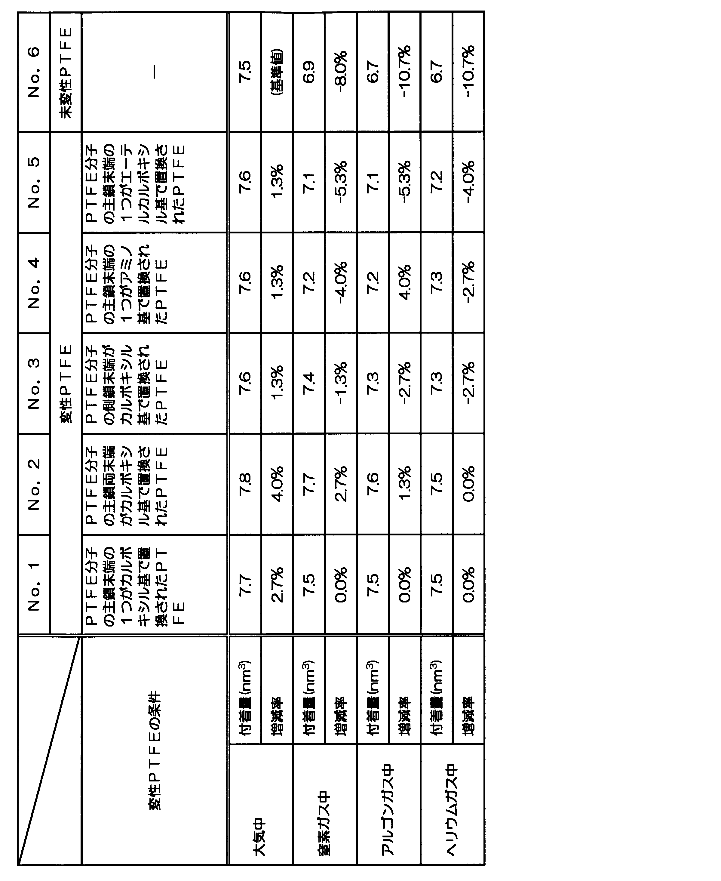
表1に示すように、No.1~5の条件はいずれも、No.6の条件と比較して、大気、窒素ガス、アルゴンガスおよびヘリウムガス中におけるアルミナ層(摺動面)への変性PTFEの付着量が多い結果となった。特に、No.6の条件では、窒素ガス、アルゴンガス、ヘリウムガスにおいて、大気中と比較して8.0~10.7%もアルミナ層への付着量が減少していたのに対し、No.1~5はいずれもNo.6と比較してアルミナ層への付着量の減少量が低く、良好な結果となった。これは、PTFEに導入した置換基がアルミナ層の表面と強力なクーロン引力を介して化学結合したためであると推察された。また、これらの中でもNo.1とNo.2の条件が窒素ガス、アルゴンガス、ヘリウムガス中におけるアルミナ層へのPTFEの付着量の減少が少なく特に良好な結果となった。
つまり、No.1~5に係る変性PTFEであれば、電気的に中性なガス(流体)を圧縮する場合であっても摩耗し難い摺動材を提供できることが強く示唆された。
したがって、これらの変性PTFEを用いて形成された摺動材を備えた流体圧縮機は、ピストンリングなどの摺動材の耐久性が向上し、長寿命化を図ることができることが強く示唆された。なお、主鎖の両端にカルボキシル基を導入したNo.2の条件が、アルミナ層への付着量が最大になるという結果になった。そのため、No.2の条件とすれば、摺動材の耐久性が向上し、長寿命化を図ることができるという効果をより確実に得ることができると推察される。
したがって、これらの変性PTFEを用いて形成された摺動材を備えた流体圧縮機は、ピストンリングなどの摺動材の耐久性が向上し、長寿命化を図ることができることが強く示唆された。なお、主鎖の両端にカルボキシル基を導入したNo.2の条件が、アルミナ層への付着量が最大になるという結果になった。そのため、No.2の条件とすれば、摺動材の耐久性が向上し、長寿命化を図ることができるという効果をより確実に得ることができると推察される。
なお、表1に示すように、No.1~6のすべての条件において、大気中での付着量が一番多い結果となった。これは、大気中では水分子が極性をもつため、界面でのクーロン引力が遮られることはなく、摺動材中の分子がアルミナ層の表面に付着し易いためであると推察された。つまり、変性PTFEで形成した摺動材は、大気中でも摩耗し難く、耐久性も向上し、長寿命化できると推察された。
また、No.1~6のすべての条件において、大気中以外の乾燥雰囲気、つまり、窒素ガス、アルゴンガス、ヘリウムガス中では、アルミナ層への付着量は概ねこの順に多い結果となった。これは、水分を含まない乾燥ガス中においては、移着しようとする摺動材中の分子とアルミナ表面との界面に介在するガス分子が電気的中性のため、クーロン引力を遮蔽し、PTFE分子の吸着の強さを弱くし、したがって、相手材表面へのPTFEの移着量を減少させるためであると推察された。
また、No.1~6のすべての条件において、大気中以外の乾燥雰囲気、つまり、窒素ガス、アルゴンガス、ヘリウムガス中では、アルミナ層への付着量は概ねこの順に多い結果となった。これは、水分を含まない乾燥ガス中においては、移着しようとする摺動材中の分子とアルミナ表面との界面に介在するガス分子が電気的中性のため、クーロン引力を遮蔽し、PTFE分子の吸着の強さを弱くし、したがって、相手材表面へのPTFEの移着量を減少させるためであると推察された。
以上、発明を実施する形態により、本発明の内容について詳細に説明したが、本発明は前記した内容に限定されるものではなく、様々な変形例が含まれる。
例えば、摺動材23aの一例としてピストンリング23を挙げて説明したが、ライダーリング24なども本明細書で説明した変性PTFEを用いて形成することができる。また、その他にも、適宜のシール材、軸受けなども本明細書で説明した変性PTFEを用いて形成することができる。
また、本明細書で説明した変性PTFEは、摺動面と、この摺動面と摺動する摺動材と、を備えた摺動機構全般に適用することができる。つまり、摺動機構における摺動材を本明細書で説明した変性PTFEを用いて形成することができる。このようにすると、流体圧縮機に限らず、電気的に中性なガス雰囲気下で使用する機械(摺動機構)における摺動材の耐久性が向上し、長寿命化を図ることができる。
例えば、摺動材23aの一例としてピストンリング23を挙げて説明したが、ライダーリング24なども本明細書で説明した変性PTFEを用いて形成することができる。また、その他にも、適宜のシール材、軸受けなども本明細書で説明した変性PTFEを用いて形成することができる。
また、本明細書で説明した変性PTFEは、摺動面と、この摺動面と摺動する摺動材と、を備えた摺動機構全般に適用することができる。つまり、摺動機構における摺動材を本明細書で説明した変性PTFEを用いて形成することができる。このようにすると、流体圧縮機に限らず、電気的に中性なガス雰囲気下で使用する機械(摺動機構)における摺動材の耐久性が向上し、長寿命化を図ることができる。
また、例えば、前記した実施形態は本発明を分かり易く説明するために詳細に説明したものであり、必ずしも説明した全ての構成を備えるものに限定されるものではない。また、ある実施形態の構成の一部を他の実施形態の構成に置き換えることが可能であり、また、ある実施形態の構成に他の実施形態の構成を加えることも可能である。また、各実施形態の構成の一部について、他の構成の追加・削除・置換をすることが可能である。
1 流体圧縮機
2 圧縮室
21 シリンダ
21a 摺動面
22 ピストン
23 ピストンリング
24 ライダーリング
25 ピストンピン
26 連結棒
2 圧縮室
21 シリンダ
21a 摺動面
22 ピストン
23 ピストンリング
24 ライダーリング
25 ピストンピン
26 連結棒
Claims (12)
- 流体を圧縮する圧縮室を備えた流体圧縮機であり、
前記圧縮室は、摺動面と、前記摺動面と摺動する摺動材と、を備え、
前記摺動材が、変性ポリテトラフルオロエチレンを用いて形成されていることを特徴とする流体圧縮機。 - 前記変性ポリテトラフルオロエチレンが、ポリテトラフルオロエチレンを構成するフッ素の少なくとも一部をカルボキシル基、エーテルカルボキシル基およびアミノ基から選択される少なくとも一つで置換したものであることを特徴とする請求項1に記載の流体圧縮機。
- 前記変性ポリテトラフルオロエチレンが、下記式(1)で表される化合物であることを特徴とする請求項1に記載の流体圧縮機。

- 前記摺動面を構成する部材は金属材料であり、その表面が前記金属材料の酸化物で被覆されていることを特徴とする請求項1に記載の流体圧縮機。
- 前記摺動面を構成する部材はアルミニウム合金であり、その表面が酸化アルミニウムで被覆されていることを特徴とする請求項1に記載の流体圧縮機。
- 前記摺動面に、前記変性ポリテトラフルオロエチレンを含む薄膜が形成されていることを特徴とする請求項1に記載の流体圧縮機。
- 前記薄膜の厚さが、1~100nmであることを特徴とする請求項6に記載の流体圧縮機。
- 前記流体が、電気的に中性なガスであることを特徴とする請求項1~7のいずれかに記載の流体圧縮機。
- 前記電気的に中性なガスが、乾燥した空気、または、窒素、アルゴンおよびヘリウムのうちの少なくとも1種を含有してなるガスであることを特徴とする請求項8に記載の流体圧縮機。
- 摺動面と、前記摺動面と摺動する摺動材と、を備え、
前記摺動材が、変性ポリテトラフルオロエチレンを用いて形成されていることを特徴とする摺動機構。 - 前記変性ポリテトラフルオロエチレンが、ポリテトラフルオロエチレンを構成するフッ素の少なくとも一部をカルボキシル基、エーテルカルボキシル基およびアミノ基から選択される少なくとも一つで置換したものであることを特徴とする請求項10に記載の摺動機構。
- 前記変性ポリテトラフルオロエチレンが、下記式(2)で表される化合物であることを特徴とする請求項10に記載の摺動機構。

Applications Claiming Priority (2)
| Application Number | Priority Date | Filing Date | Title |
|---|---|---|---|
| JP2012-139583 | 2012-06-21 | ||
| JP2012139583A JP6068016B2 (ja) | 2012-06-21 | 2012-06-21 | 流体圧縮機および摺動機構 |
Publications (1)
| Publication Number | Publication Date |
|---|---|
| WO2013190858A1 true WO2013190858A1 (ja) | 2013-12-27 |
Family
ID=49768469
Family Applications (1)
| Application Number | Title | Priority Date | Filing Date |
|---|---|---|---|
| PCT/JP2013/050626 Ceased WO2013190858A1 (ja) | 2012-06-21 | 2013-01-16 | 流体圧縮機および摺動機構 |
Country Status (2)
| Country | Link |
|---|---|
| JP (1) | JP6068016B2 (ja) |
| WO (1) | WO2013190858A1 (ja) |
Families Citing this family (2)
| Publication number | Priority date | Publication date | Assignee | Title |
|---|---|---|---|---|
| JP7002401B2 (ja) | 2018-04-27 | 2022-02-10 | 株式会社神戸製鋼所 | 圧縮機 |
| JP7631399B2 (ja) * | 2023-03-31 | 2025-02-18 | 株式会社神戸製鋼所 | ピストンリング及びピストンリング複合体 |
Citations (3)
| Publication number | Priority date | Publication date | Assignee | Title |
|---|---|---|---|---|
| JPS6381159A (ja) * | 1986-09-24 | 1988-04-12 | Japan Synthetic Rubber Co Ltd | 熱可塑性エラストマ−組成物 |
| WO1995033782A1 (en) * | 1994-06-09 | 1995-12-14 | Daikin Industries, Ltd. | Fluoroolefin, fluoropolymer, and thermoplastic resin composition containing the polymer |
| JP2009085051A (ja) * | 2007-09-28 | 2009-04-23 | Hitachi Ltd | 摺動材及び流体圧縮機械 |
Family Cites Families (1)
| Publication number | Priority date | Publication date | Assignee | Title |
|---|---|---|---|---|
| DE10351812B4 (de) * | 2003-10-30 | 2006-04-20 | Leibniz-Institut Für Polymerforschung Dresden E.V. | Modifizierte Perfluor-Kunststoffe und Verfahren zu ihrer Herstellung |
-
2012
- 2012-06-21 JP JP2012139583A patent/JP6068016B2/ja active Active
-
2013
- 2013-01-16 WO PCT/JP2013/050626 patent/WO2013190858A1/ja not_active Ceased
Patent Citations (3)
| Publication number | Priority date | Publication date | Assignee | Title |
|---|---|---|---|---|
| JPS6381159A (ja) * | 1986-09-24 | 1988-04-12 | Japan Synthetic Rubber Co Ltd | 熱可塑性エラストマ−組成物 |
| WO1995033782A1 (en) * | 1994-06-09 | 1995-12-14 | Daikin Industries, Ltd. | Fluoroolefin, fluoropolymer, and thermoplastic resin composition containing the polymer |
| JP2009085051A (ja) * | 2007-09-28 | 2009-04-23 | Hitachi Ltd | 摺動材及び流体圧縮機械 |
Also Published As
| Publication number | Publication date |
|---|---|
| JP6068016B2 (ja) | 2017-01-25 |
| JP2014005732A (ja) | 2014-01-16 |
Similar Documents
| Publication | Publication Date | Title |
|---|---|---|
| CN101788015B (zh) | 一种三层自润滑耐磨滑动轴承材料及其制备方法 | |
| KR100705728B1 (ko) | 마찰공학적 부하를 받는 표면용 알루미늄 합금 | |
| US5419970A (en) | Method for making a composite aluminum article | |
| KR101820487B1 (ko) | 엔진 피스톤 코팅용 수지 조성물 및 그 제조방법 | |
| JP2005187617A (ja) | 摺動材料 | |
| KR20110100259A (ko) | 베어링 | |
| JP4025832B2 (ja) | 圧縮機 | |
| WO2013190858A1 (ja) | 流体圧縮機および摺動機構 | |
| CN103298972B (zh) | 用于往复式压缩机的活塞组件 | |
| CN105968983A (zh) | 一种改性石墨烯聚四氟乙烯复合固体润滑涂层的制备方法 | |
| JP6523595B2 (ja) | 乾燥ガス圧縮機 | |
| CN108456883B (zh) | 一种基体表面碳基减摩耐磨薄膜的制备方法 | |
| JP2005146366A (ja) | 摺動部材 | |
| EP2034217B1 (en) | Oilless chain and method of producing oilless chain | |
| JPH08208930A (ja) | 摺動用組成物及びその摺動部材 | |
| EP4160017B1 (en) | Compressor | |
| JP2002327750A (ja) | 複層軸受 | |
| JPH06122887A (ja) | 摺動部材用組成物 | |
| CN104214074B (zh) | 滑动部件及使用其的气体压缩机和分析仪器 | |
| JP2005036198A (ja) | シール材及びそれを備えたスクロール流体機械 | |
| JP2005305395A (ja) | アルミニウム系基材の塗装方法及びアルミニウム系基材塗装物 | |
| JP4128442B2 (ja) | シール材及びそれを備えたスクロール流体機械 | |
| JP2012031756A (ja) | 無給油式往復動型圧縮機 | |
| US20140020555A1 (en) | Piston assembly for alternative compressor | |
| JP2024501043A5 (ja) |
Legal Events
| Date | Code | Title | Description |
|---|---|---|---|
| 121 | Ep: the epo has been informed by wipo that ep was designated in this application |
Ref document number: 13807871 Country of ref document: EP Kind code of ref document: A1 |
|
| NENP | Non-entry into the national phase |
Ref country code: DE |
|
| 122 | Ep: pct application non-entry in european phase |
Ref document number: 13807871 Country of ref document: EP Kind code of ref document: A1 |