WO2013190835A2 - Portable device - Google Patents
Portable device Download PDFInfo
- Publication number
- WO2013190835A2 WO2013190835A2 PCT/JP2013/003815 JP2013003815W WO2013190835A2 WO 2013190835 A2 WO2013190835 A2 WO 2013190835A2 JP 2013003815 W JP2013003815 W JP 2013003815W WO 2013190835 A2 WO2013190835 A2 WO 2013190835A2
- Authority
- WO
- WIPO (PCT)
- Prior art keywords
- running
- axis
- radio wave
- vibration frequency
- body vibration
- Prior art date
- Legal status (The legal status is an assumption and is not a legal conclusion. Google has not performed a legal analysis and makes no representation as to the accuracy of the status listed.)
- Ceased
Links
Images


Classifications
-
- H—ELECTRICITY
- H04—ELECTRIC COMMUNICATION TECHNIQUE
- H04W—WIRELESS COMMUNICATION NETWORKS
- H04W4/00—Services specially adapted for wireless communication networks; Facilities therefor
- H04W4/02—Services making use of location information
- H04W4/025—Services making use of location information using location based information parameters
- H04W4/027—Services making use of location information using location based information parameters using movement velocity, acceleration information
-
- A—HUMAN NECESSITIES
- A61—MEDICAL OR VETERINARY SCIENCE; HYGIENE
- A61B—DIAGNOSIS; SURGERY; IDENTIFICATION
- A61B5/00—Measuring for diagnostic purposes; Identification of persons
- A61B5/103—Measuring devices for testing the shape, pattern, colour, size or movement of the body or parts thereof, for diagnostic purposes
- A61B5/11—Measuring movement of the entire body or parts thereof, e.g. head or hand tremor or mobility of a limb
- A61B5/1112—Global tracking of patients, e.g. by using GPS
-
- A—HUMAN NECESSITIES
- A61—MEDICAL OR VETERINARY SCIENCE; HYGIENE
- A61B—DIAGNOSIS; SURGERY; IDENTIFICATION
- A61B5/00—Measuring for diagnostic purposes; Identification of persons
- A61B5/103—Measuring devices for testing the shape, pattern, colour, size or movement of the body or parts thereof, for diagnostic purposes
- A61B5/11—Measuring movement of the entire body or parts thereof, e.g. head or hand tremor or mobility of a limb
- A61B5/1121—Determining geometric values, e.g. centre of rotation or angular range of movement
- A61B5/1122—Determining geometric values, e.g. centre of rotation or angular range of movement of movement trajectories
-
- A—HUMAN NECESSITIES
- A61—MEDICAL OR VETERINARY SCIENCE; HYGIENE
- A61B—DIAGNOSIS; SURGERY; IDENTIFICATION
- A61B5/00—Measuring for diagnostic purposes; Identification of persons
- A61B5/68—Arrangements of detecting, measuring or recording means, e.g. sensors, in relation to patient
- A61B5/6801—Arrangements of detecting, measuring or recording means, e.g. sensors, in relation to patient specially adapted to be attached to or worn on the body surface
- A61B5/6802—Sensor mounted on worn items
- A61B5/681—Wristwatch-type devices
-
- A—HUMAN NECESSITIES
- A61—MEDICAL OR VETERINARY SCIENCE; HYGIENE
- A61B—DIAGNOSIS; SURGERY; IDENTIFICATION
- A61B5/00—Measuring for diagnostic purposes; Identification of persons
- A61B5/72—Signal processing specially adapted for physiological signals or for diagnostic purposes
- A61B5/7235—Details of waveform analysis
- A61B5/7242—Details of waveform analysis using integration
-
- A—HUMAN NECESSITIES
- A63—SPORTS; GAMES; AMUSEMENTS
- A63B—APPARATUS FOR PHYSICAL TRAINING, GYMNASTICS, SWIMMING, CLIMBING, OR FENCING; BALL GAMES; TRAINING EQUIPMENT
- A63B24/00—Electric or electronic controls for exercising apparatus of preceding groups; Controlling or monitoring of exercises, sportive games, training or athletic performances
-
- G—PHYSICS
- G01—MEASURING; TESTING
- G01C—MEASURING DISTANCES, LEVELS OR BEARINGS; SURVEYING; NAVIGATION; GYROSCOPIC INSTRUMENTS; PHOTOGRAMMETRY OR VIDEOGRAMMETRY
- G01C22/00—Measuring distance traversed on the ground by vehicles, persons, animals or other moving solid bodies, e.g. using odometers, using pedometers
- G01C22/006—Pedometers
-
- G—PHYSICS
- G01—MEASURING; TESTING
- G01P—MEASURING LINEAR OR ANGULAR SPEED, ACCELERATION, DECELERATION, OR SHOCK; INDICATING PRESENCE, ABSENCE, OR DIRECTION, OF MOVEMENT
- G01P15/00—Measuring acceleration; Measuring deceleration; Measuring shock, i.e. sudden change of acceleration
- G01P15/02—Measuring acceleration; Measuring deceleration; Measuring shock, i.e. sudden change of acceleration by making use of inertia forces using solid seismic masses
-
- G—PHYSICS
- G01—MEASURING; TESTING
- G01P—MEASURING LINEAR OR ANGULAR SPEED, ACCELERATION, DECELERATION, OR SHOCK; INDICATING PRESENCE, ABSENCE, OR DIRECTION, OF MOVEMENT
- G01P7/00—Measuring speed by integrating acceleration
-
- G—PHYSICS
- G01—MEASURING; TESTING
- G01S—RADIO DIRECTION-FINDING; RADIO NAVIGATION; DETERMINING DISTANCE OR VELOCITY BY USE OF RADIO WAVES; LOCATING OR PRESENCE-DETECTING BY USE OF THE REFLECTION OR RERADIATION OF RADIO WAVES; ANALOGOUS ARRANGEMENTS USING OTHER WAVES
- G01S19/00—Satellite radio beacon positioning systems; Determining position, velocity or attitude using signals transmitted by such systems
- G01S19/01—Satellite radio beacon positioning systems transmitting time-stamped messages, e.g. GPS [Global Positioning System], GLONASS [Global Orbiting Navigation Satellite System] or GALILEO
- G01S19/13—Receivers
- G01S19/14—Receivers specially adapted for specific applications
- G01S19/19—Sporting applications
-
- G—PHYSICS
- G01—MEASURING; TESTING
- G01S—RADIO DIRECTION-FINDING; RADIO NAVIGATION; DETERMINING DISTANCE OR VELOCITY BY USE OF RADIO WAVES; LOCATING OR PRESENCE-DETECTING BY USE OF THE REFLECTION OR RERADIATION OF RADIO WAVES; ANALOGOUS ARRANGEMENTS USING OTHER WAVES
- G01S19/00—Satellite radio beacon positioning systems; Determining position, velocity or attitude using signals transmitted by such systems
- G01S19/38—Determining a navigation solution using signals transmitted by a satellite radio beacon positioning system
- G01S19/39—Determining a navigation solution using signals transmitted by a satellite radio beacon positioning system the satellite radio beacon positioning system transmitting time-stamped messages, e.g. GPS [Global Positioning System], GLONASS [Global Orbiting Navigation Satellite System] or GALILEO
- G01S19/42—Determining position
- G01S19/48—Determining position by combining or switching between position solutions derived from the satellite radio beacon positioning system and position solutions derived from a further system
- G01S19/49—Determining position by combining or switching between position solutions derived from the satellite radio beacon positioning system and position solutions derived from a further system whereby the further system is an inertial position system, e.g. loosely-coupled
-
- G—PHYSICS
- G01—MEASURING; TESTING
- G01S—RADIO DIRECTION-FINDING; RADIO NAVIGATION; DETERMINING DISTANCE OR VELOCITY BY USE OF RADIO WAVES; LOCATING OR PRESENCE-DETECTING BY USE OF THE REFLECTION OR RERADIATION OF RADIO WAVES; ANALOGOUS ARRANGEMENTS USING OTHER WAVES
- G01S5/00—Position-fixing by co-ordinating two or more direction or position line determinations; Position-fixing by co-ordinating two or more distance determinations
- G01S5/01—Determining conditions which influence positioning, e.g. radio environment, state of motion or energy consumption
- G01S5/017—Detecting state or type of motion
-
- G—PHYSICS
- G01—MEASURING; TESTING
- G01S—RADIO DIRECTION-FINDING; RADIO NAVIGATION; DETERMINING DISTANCE OR VELOCITY BY USE OF RADIO WAVES; LOCATING OR PRESENCE-DETECTING BY USE OF THE REFLECTION OR RERADIATION OF RADIO WAVES; ANALOGOUS ARRANGEMENTS USING OTHER WAVES
- G01S5/00—Position-fixing by co-ordinating two or more direction or position line determinations; Position-fixing by co-ordinating two or more distance determinations
- G01S5/01—Determining conditions which influence positioning, e.g. radio environment, state of motion or energy consumption
- G01S5/018—Involving non-radio wave signals or measurements
-
- A—HUMAN NECESSITIES
- A61—MEDICAL OR VETERINARY SCIENCE; HYGIENE
- A61B—DIAGNOSIS; SURGERY; IDENTIFICATION
- A61B2562/00—Details of sensors; Constructional details of sensor housings or probes; Accessories for sensors
- A61B2562/02—Details of sensors specially adapted for in-vivo measurements
- A61B2562/0219—Inertial sensors, e.g. accelerometers, gyroscopes, tilt switches
Definitions
- the present invention relates to a portable device including a reception module configured to receive radio waves from position information satellites and an acceleration sensor.
- a running watch that displays speed information and the like grasped by processing signals from position information satellites such as GPS (Global Positioning System) satellites, when radio wave information from the position information satellites cannot be received in a tunnel or the like, the problem is how to display running speed.
- position information satellites such as GPS (Global Positioning System) satellites
- Cited Literature 1 since the user needs to wear a foot sensor, a wrist sensor, and a chest sensor in the respective regions, there is a problem in that the wearing of the sensors is troublesome. There is also a problem in that battery replacement is necessary for these sensors and, when old batteries are used, the user fails in data communication and recording because of a voltage shortage.
- An advantage of some aspects of the invention is to provide a portable device that has no trouble of sensor wearing and can surely and accurately perform speed calculation irrespective of what kind of a user uses the portable device and even when signals from position information satellites cannot be received.
- An aspect of the invention is directed to a portable device including: a radio-wave receiving unit configured to receive a radio wave from a position information satellite; a detecting unit capable of detecting a body vibration frequency in a direction in which the body of a user moves up and down during running; a display unit configured to display running information; a specifying unit configured to specify, when a reception state of the radio wave satisfies a predetermined standard, a correlation between the body vibration frequency detected by the detecting unit and speed information grasped by processing a signal included in the radio wave; and an estimating unit configured to estimate, when the reception state of the radio wave does not satisfy the predetermined standard, running speed or a running pace on the basis of the body vibration frequency detected by the detecting unit and the correlation specified by the specifying unit.
- the estimating unit estimates running speed or a running pace on the basis of the body vibration frequency detected by the detecting unit and the correlation specified by the specifying unit.
- the detecting unit since the detecting unit is provided in the portable device, there is no trouble of wearing sensors in regions of the body other than the portable device. Since running speed or a running pace is estimated on the basis of the body vibration frequency in the direction in which the body of the user moves up and down during running, it is possible to surely and accurately estimate running speed or a running pace irrespective of a step and an exercise capacity of the user.
- the portable device of the aspect of the invention may be configured such that the detecting unit includes an acceleration sensor configured to detect accelerations in three axis directions of an X axis, a Y axis, and a Z axis and detect, as the body vibration frequency, a frequency of vibration in a direction of an axis closest to the gravity direction among frequencies of vibrations obtained by the acceleration sensor.
- the detecting unit since the detecting unit includes the tri-axis acceleration sensor, it is possible to obtain accelerations concerning the respective X, Y, and Z axes.
- an axis reflecting vibration in the up down direction most is different depending on a form of wearing of the portable device by the user.
- the frequency of the vibration of the axis closest to the gravity direction is specified as the body vibration frequency in the form of wearing the portable device by the user. Therefore, it is possible to estimate running speed or a running pace on the basis of the body vibration frequency in the direction in which the body of the user moves up and down during running and it is possible to surely and accurately estimate running speed or a running pace irrespective of a step and an exercise capacity of the user.
- the portable device of the aspect of the invention may be configured such that the detecting unit includes an acceleration sensor configured to detect accelerations in three axis directions of an X axis, a Y axis, and a Z axis, combine waveforms of vibrations of the respective axes obtained by the acceleration sensor, and detect a frequency of a combined waveform as the body vibration frequency.
- the portable device in this way, it is possible to estimate running speed or a running pace on the basis of the body vibration frequency in the direction in which the body of the user moves up and down during running and it is possible to surely and accurately estimate running speed or a running pace irrespective of a step and an exercise capacity of the user.
- the portable device may be configured such that the detecting unit includes an acceleration sensor configured to detect accelerations in three axis directions of an X axis, a Y axis, and a Z axis and detect, as the body vibration frequency, a frequency of a waveform of an axis having largest amplitude among waveforms of vibrations of the respective axes obtained by the acceleration sensor.
- the portable device in this way, it is possible to estimate running speed or a running pace on the basis of the body vibration frequency in the direction in which the body of the user moves up and down during running and it is possible to surely and accurately estimate running speed or a running pace irrespective of a step and an exercise capacity of the user.
- the portable device may be configured such that the specifying unit specifies, as a linear expression, the correlation between the body vibration frequency and the speed information grasped by processing the signal included in the radio wave, and the estimating unit estimates running speed or a running pace from the body vibration frequency on the basis of the linear expression.
- the specifying unit specifies, as a linear expression, the correlation between the body vibration frequency and the speed information grasped by processing the signal included in the radio wave
- the estimating unit estimates running speed or a running pace from the body vibration frequency on the basis of the linear expression.
- the portable device may be configured such that the specifying unit generates a table for specifying the correlation between the body vibration frequency and the speed information grasped by processing the signal included in the radio wave, and the estimating unit estimates running speed or a running pace from the body vibration frequency referring to the table.
- the portable device may be configured such that, when the reception state of the radio wave satisfies the predetermined standard, a running distance is calculated from the speed information grasped by processing the signal included in the radio wave, and when the reception state of the radio wave does not satisfy the predetermined standard, the running distance is calculated on the basis of the running speed and time or the running pace and time estimated by the estimating unit.
- the portable device may be configured such that, when the reception state of the radio wave satisfies the predetermined standard, a running distance is calculated from the position information grasped by processing the signal included in the radio wave, and when the reception state of the radio wave does not satisfy the predetermined standard, the running distance is calculated on the basis of the running speed and time or the running pace or time estimated by the estimating unit.
- Fig. 1 is an overall diagram of a GPS system including a GPS running watch according to an embodiment of the invention.
- Fig. 2 is a plan view of the GPS running watch.
- Fig. 3 is a block diagram showing a circuit configuration of the GPS running watch.
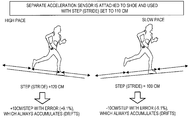
- Fig. 4 is a diagram for explaining an error of a step detected using a separate acceleration sensor attached to a shoe.
- Fig. 5 is a graph showing a relation between a body vibration frequency and running speed.
- Fig. 6 is a diagram for explaining processing at GPS reception time and at GPS reception impossible time in the embodiment of the invention.
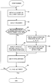
- Fig. 7 is a flowchart for explaining calculation processing for speed and a distance in the embodiment of the invention.
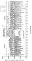
- Fig. 8 is a graph showing output waveforms of axes of the acceleration sensor.
- Fig. 9 is graphs of relations between body vibration frequencies and running speeds calculated concerning various users.
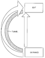
- Fig. 10 is a diagram for explaining a difference between measuring methods for a running distance during running in a curved tunnel.
- Fig. 11 is a diagram showing directions of the axes of the acceleration sensor of the GPS running watch 100 worn on the arm.
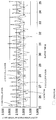
- Fig. 12 is a graph showing vibrations in the axis directions caused during normal running and when a user looks at a screen of the GPS running watch.
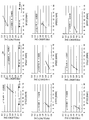
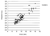
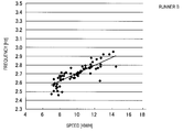
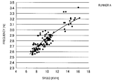
- Fig. 13 is a graph obtained by calculating a relation between a body vibration frequency and running speed of a runner A.
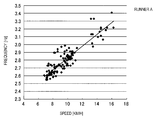
- Fig. 14 is a graph showing a linear expression calculated from data shown in Fig. 13.
- Fig. 14 is a graph showing a linear expression calculated from data shown in Fig. 13.
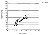
- Fig. 15 is a graph obtained by calculating a relation between a body vibration frequency and running speed of a runner B.
- Fig. 16 is a graph showing a linear expression calculated from data shown in Fig. 15.
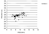
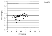
- Fig. 17 is a graph obtained by calculating a relation between a body vibration frequency and running speed of a runner C.
- Fig. 18 is a graph showing a linear expression calculated from data shown in Fig. 17.
- Fig. 19 is a graph showing a quadratic equation calculated from the data shown in Fig. 13.
- Fig. 20 is a graph showing a quadratic expression calculated from the data shown in Fig. 15.
- Fig. 21 is a graph showing a quadratic expression calculated from the data shown in Fig. 17.
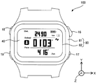
- FIG. 1 is an overall diagram of a GPS system including a GPS running watch 100 used as a portable device according to an embodiment of the invention.
- the GPS running watch 100 is a portable device that displays speed information and the like grasped by processing radio waves (radio signals) from GPS satellites 20.
- the GPS running watch 100 displays time on a surface (hereinafter referred to as "front surface”) on the opposite side of a surface in contact with the arm (hereinafter referred to as "rear surface").
- the GPS satellites 20 are position information satellites that revolve on a predetermined orbit in the sky of the earth.
- the GPS satellites 20 transmit a navigation message to the ground while superimposing the navigation message on a 1.57542 GHz radio wave (a L1 wave).
- a 1.57542 GHz radio wave on which the navigation message is superimposed is referred to as "satellite signal".
- the satellite signal is a right-handed circularly polarized wave.
- the respective GPS satellites 20 superimpose 1023 chip (1 ms period) peculiar patterns called C/A codes (Coarse/Acquisition Codes) on satellite signals.
- the C/A codes have chips of +1 or -1 and look like random patterns. Therefore, it is possible to detect a C/A code superimposed on the satellite signal by calculating a correlation between the satellite signals and the patterns of the C/A codes.
- the GPS satellites 20 are mounted with atomic clocks. Extremely accurate time information (hereinafter referred to as "GPS time information") measured by the atomic clocks is included in the satellite signal. A slight time error of atomic clocks mounted on the GPS satellites 20 is measured by a control segment on the ground. A time correction parameter for correcting the time error is also included in the satellite signal.
- the GPS running watch 100 receives the satellite signal transmitted from one GPS satellite 20 and corrects internal time to accurate time using the GPS time information and the time correction parameter included in the satellite signal.
- Satellite orbit information indicating positions on an orbit of the GPS satellites 20 is also included in the satellite signal.
- the GPS running watch 100 can perform a positioning calculation using the GPS time information and the satellite orbit information.
- the positioning calculation is performed on the premise that a certain degree of an error is included in the internal time of the GPS running watch 100. That is, in addition to x, y, and z parameters for specifying a three-dimensional position of the GPS running watch 100, a time error is also an unknown number. Therefore, in general, the GPS running watch 100 receives satellite signals respectively transmitted from four or more GPS satellites and performs the positioning calculation using GPS time information and satellite orbit information included in the satellite signals.
- Fig. 2 is a plan view of the GPS running watch 100.
- the GPS running watch 100 includes an armor case 80.
- the armor case 80 is configured by fitting a cover glass 82 formed of glass or plastic in a case 81 formed of plastic.
- the armor case is configured by two components.
- the armor case may be configured by one component.
- the armor case may be configured by three components using a back cover.
- a liquid crystal panel 40 is arranged under the cover glass 82.
- the liquid crystal panel 40 is configured to display running information such as running speed, a running distance, a running time, a running pace (e.g., a required time (minutes) per 1 km), a pitch (the number of steps per one minute), and the number of steps.
- the GPS running watch 100 can be switched to a running mode for displaying running speed and the like, a time display mode for displaying time, and the like by manually operating operation buttons 16 to 19.
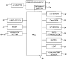
- Fig. 3 is a block diagram showing a circuit configuration of the GPS running watch 100.
- the GPS running watch 100 includes an MCU 30, a power supply circuit 31, a liquid-crystal-panel display unit 32, a flash ROM 33, a GPS module 34, a radio communication unit 35, a buzzer 36, a light 37, an acceleration sensor 38, a quartz oscillator 39, a reset circuit 41, and the operation buttons 16 to 19.
- the MCU 30 includes, on the inside thereof, a memory configured to store a program.
- the MCU 30 is configured to perform control of the units of the GPS running watch 100 and perform storage processing for a running state of a user, speed calculation processing, and the like explained below.
- the power supply circuit 31 charges a secondary battery 31a.
- the secondary battery 31a supplies driving power to the liquid-crystal-panel display unit 32, the GPS module 34, and the like.
- the GPS module 34 performs processing for acquiring satellite information such as satellite orbit information, GPS time information, or position information included in a navigation message from a satellite signal in a 1.5 GHz band extracted by a not-shown SAW filter.
- satellite information such as satellite orbit information, GPS time information, or position information included in a navigation message from a satellite signal in a 1.5 GHz band extracted by a not-shown SAW filter.
- time difference information is stored in the flash ROM 33.
- the time difference information is information in which time difference data (e.g., a correction amount for UTC associated with a coordinate value (e.g., latitude and longitude) is defined.
- a correlation between a body vibration frequency and speed is also recorded in the flash ROM 33.
- the radio communication unit 35 is configured to be capable of performing radio communication between the GPS running watch 100 and a personal computer and the like and transmitting log data and the like stored in the GPS running watch 100 to the personal computer and the like.
- the buzzer 36 is used for, for example, informing completion of setting processing by the user.
- the light 37 is used to irradiate light on the liquid crystal panel 40 according to operation of an operation button by the user and facilitate visual recognition by the user at night and the like.
- the acceleration sensor 38 is a sensor capable of detecting accelerations in three axis directions, i.e., an X-axis direction equivalent to the lateral direction, a Y-axis direction equivalent to the longitudinal direction, and a Z-axis direction equivalent to a direction perpendicular to the cover glass 82 of the GPS running watch 100 when the GPS running watch 100 is viewed from the front as shown in Fig. 2. That is, in a state in which a user wears the GPS running watch 100 on the arm and runs with the thumb facing upward, a running direction of the user is the X-axis direction, an up down moving direction of the user (the gravity direction) is the Y-axis direction, and a left right moving direction of the user is the Z-axis direction.
- the acceleration sensor 38 is explained in detail below.
- the quartz oscillator 39 is a quartz oscillation circuit attached with a temperature compensation circuit.
- the quartz oscillator 39 generates a reference clock signal having a substantially fixed frequency irrespective of temperature.
- the reset circuit 41 is used for resetting the operation of the GPS running watch 100.
- the operation buttons 16 to 19 are used to switch an operation mode (the running mode, the time display mode, etc.) and perform display setting for the liquid crystal panel 40 and various setting inputs.
- Speed estimation processing and distance calculation processing performed by using the acceleration sensor of the GPS running watch Speed estimation processing and distance calculation processing performed by using the acceleration sensor of the GPS running watch 100 according to this embodiment are explained in detail. For example, when radio wave information from the GPS satellites cannot be received or when radio waves from the GPS satellites are weak, speed information grasped by processing signals included in the radio wave information from the GPS satellites cannot be used.
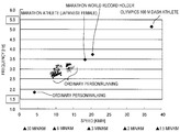
- a body vibration frequency i.e., a frequency of vibration of the body of a runner moving up and down during running does not depend on the step of the runner and has a correlation with actual running speed of the runner. It has also been found that a relation between the body vibration frequency and the running speed does not depend on a difference of an exercise capacity of the runner either and, as shown in Fig. 5, is in a substantially proportional relation in runners ranging from general runners to Olympics athletes of field and track events and in a relation in which, as the body vibration frequency is higher, the running speed is higher. For example, it has been found that, as shown in Fig.
- the body vibration frequency is about 2.5 Hz to 3.2 Hz
- the body vibration frequency is about 3.5 Hz to 3.7 Hz
- the body vibration frequency is about 5.1 Hz.
- a frequency of vibration in the Y-axis direction of the acceleration sensor 38 is set as a body vibration frequency of the user and a correlation between the body vibration frequency and running speed is specified.
- the body vibration frequency of the user is measured, speed information grasped by processing signals included in the radio wave information from the GPS satellites at that point is set as running speed, and data of the body vibration frequency of the user and data of the running speed are recorded in association with each other.
- a correlation between the body vibration frequency of the user and the running speed is specified as a linear expression.
- the linear expression for example, the method of least squares is used.
- FIG. 7 A specific example of the speed estimation processing and the distance calculation processing in this embodiment is explained on the basis of a flowchart of Fig. 7 and an output waveform chart of the acceleration sensor of Fig. 8.
- the user operates the operation button 16 of the GPS running watch 100 to start measurement of speed and a distance.
- amplitude values of vibrations in the respective X-axis, Y-axis, and Z-axis directions are output from the acceleration sensor 38 as shown in Fig. 8. Therefore, as an example, the MCU 30 detects a lower peak value of an acceleration waveform in the Y-axis direction among acceleration waveforms output from the acceleration sensor 38 and stores, as required, time when the lower peak value is obtained (Fig. 7: S1).
- the MCU 30 detects, from the time when the lower peak value is obtained, the number of vibrations in the Y-axis direction per hour, i.e., a frequency of vibration in the Y-axis direction and stores the frequency (Fig. 7: S2). Subsequently, the MCU 30 determines whether a reception state of radio waves from the GPS satellites satisfies a predetermined standard (Fig. 7: S3). When the reception state of the radio waves from the GPS satellites satisfies the predetermined standard (Fig. 7: S3: YES), the MCU 30 specifies a linear expression from the stored frequency and speed information grasped by processing signals from the GPS satellites at the time when the lower peak value is obtained (Fig. 7: S4).
- the MCU 30 displays, as running speed, the speed information grasped by processing the signals from the GPS satellites at that time and multiplies the acquired speed information with time from the time when the speed information is acquired last time to the time when the speed information is acquired this time to calculate a running distance from the time when the speed information is acquired last time to the time when the speed information is acquired this time (Fig. 7: S5).
- the MCU 30 adds the calculated distance to the current total distance (Fig. 7: S7).
- the display of the total distance may be performed as required or may be performed according to operation of the operation button by the user.
- the MCU 30 determines whether the running of the user has ended (Fig. 7: S8).
- the MCU 30 only has to determine that the running has ended.
- the running has not ended (Fig. 7: S8: NO)
- the MCU 30 repeats the processing explained above.
- the MCU 30 applies the body vibration frequency obtained from the output of the acceleration sensor 38 to the calculated linear expression to calculate running speed and displays the running speed.
- the MCU 30 multiplies the calculated running speed with time from the time when the speed information is acquired last time or when the running speed is calculated last time to the time when the running speed is calculated this time to calculate a running distance from the time when the speed information is acquired last time or when the running speed is calculated last time to the time when the running speed is calculated this time and displays the running distance (Fig. 7: S6).
- the MCU 30 adds the calculated distance to the current total distance (Fig. 7: S7).
- the display of the total distance may be performed as required or may be performed according to operation of the operation button by the user.
- the MCU 30 determines whether the running of the user has ended (Fig. 7: S8).
- the MCU 30 may determine that the running has ended.
- the MCU 30 repeats the processing explained above.
- the specified linear expression may be stored as it is even after the running has ended or may be cleared when another user uses the GPS running watch 100.
- the user when the user runs in a section where the reception state of the radio waves from the GPS satellites does not satisfy the predetermined standard, for example, when the user runs in a tunnel or the like, it is possible to estimate running speed of the user on the basis of a linear expression specified while the reception state of the radio waves from the GPS satellites satisfies the predetermined standard. Therefore, the user can always check running speed of the user and can run at a desired pace or an appropriate pace.
- the processing for calculating a running distance from estimated running speed and adding the running distance to the current total distance is performed. Therefore, for example, as shown in Fig. 10, even when the user runs in a curved tunnel, the user can accurately learn a running distance.
- running speed and a running distance are calculated from the body vibration frequency measured by the acceleration sensor 38 and the specified linear expression. Therefore, even when the user runs in the curved tunnel shown in Fig. 10, the user can accurately learn the running distance.
- the frequency of the vibration in the Y-axis direction of the acceleration sensor 38 is calculated and set as the body vibration frequency.
- the direction of the vibration to be set as the body vibration frequency only has to be a direction in which the body of the user moves up and down during running.
- Vibration of an axis closest to the gravity direction only has to be used as the vibration.
- the vibration of the axis closest to the gravity direction means vibration in an axis direction in which amplitude is the largest among vibrations in the X-axis direction, the Y-axis direction, and the Z-axis direction.
- the amplitude of the vibration in the Y-axis direction shown in Fig. 11 is the largest. Therefore, the vibration in the Y-axis direction is used as the vibration of the axis closest to the gravity direction.
- the amplitude of the vibration in the Z-axis direction which is the direction perpendicular to the liquid crystal panel of the GPS running watch 100, is the largest. Therefore, in this case, the vibration in the Z-axis direction is used as the vibration of the axis closest to the gravity direction.
- FIG. 12 An example of the vibrations in the respective axis directions is shown in Fig. 12.
- Fig. 12 it is seen that, in the state in which the user wears the GPS running watch 100 on the arm and is running with the thumb facing upward, the amplitude of the vibration in the Y-axis direction is the largest. Therefore, it is seen that, when the user is looking at the screen of the GPS running watch 100, as shown in a region A of Fig. 12, the amplitude of the vibration in the Z-axis direction is the largest.
- the vibration in the axis direction in which the amplitude is the largest is adopted as the vibration of the axis closest to the gravity direction.
- a frequency of the vibration of the axis closest to the gravity direction is calculated and set as the body vibration frequency.
- the invention is not limited to such an example.
- a frequency of a waveform obtained by combining vibration waveforms of the axes of the acceleration sensor 38 may be set as the body vibration frequency.
- a linear expression is specified from the relation between the body vibration frequency and the running speed and the specified linear expression is stored.
- a table for specifying a correlation between the body vibration frequency and the running speed may be generated and stored.
- Running speed may be estimated using the table.
- the multi-axis acceleration sensor 38 is provided in the GPS running watch 100 to estimate running speed. Therefore, it is unnecessary to attach a sensor separate from the running watch to the foot or the chest. This makes it possible to facilitate preparation before running.
- the acceleration sensor 38 is incorporated in the GPS running watch 100. Therefore, there is no risk of a failure of data recording due to a dead battery or an old battery that occurs when the separate sensor is used.
- the motion of body vibration having large amplitude is detected. Therefore, even if the motions of the arms during running are various and complicated depending on users, it is possible to accurately catch a waveform peak and improve accuracy of an output value. Further, some runner does not swing the arms when running. However, in this embodiment, since the motion of the body vibration having large amplitude is detected, even when such a runner who does not swing the arms uses the GPS running watch 100, it is possible to improve accuracy of an output value.
- a linear expression is calculated from the relation between the body vibration frequency and the running speed.
- a quadratic expression may be calculated.
- Figs. 13, 15, and 17 are graphs respectively obtained by plotting data indicating relations between body vibration frequencies and running speeds of a runner A, a runner B, and a runner C.
- Figs. 14, 16, and 18 are respectively examples in which linear expressions are calculated by the method of least squares on the basis of the data shown in Figs. 13, 15, and 17.
- Figs. 19, 20, and 21 are respectively examples in which quadratic expressions are calculated on the basis of the data shown in Figs. 13, 15, and 17.
- the method of least squares only has to be used in the same manner as calculating the linear expression.
- the GPS satellite 20 is explained as an example of the position information satellite included in the GPS system.
- the GPS system only has to be other global navigation satellite systems (GNSS) such as GALILEO (EU), GLONASS (Russia), and BEIDOU (China) or a GPS system such as the SBAS including position information satellites that transmit satellite signals such as stationary satellites and quasi-zenith satellites.
- GNSS global navigation satellite systems
- EU GALILEO
- GLONASS Russia
- BEIDOU China
- the GPS running watch 100 may be configured to acquire speed information grasped by processing radio waves (radio signals) from position information satellites including satellites other than the GPS satellites 20.
- the speed information may be speed information itself included in radio waves from the position information satellites or may be information concerning groundspeed calculated from a running distance (a moving distance) and an elapsed time obtained by performing a positioning calculation using GPS time information and satellite orbit information included in the radio waves from the position information satellites.
- the correlation between the body vibration frequency and the running speed is specified.
- a correlation between the body vibration frequency and the running pace may be specified.
- the running pace may be specified from the specified correlation between the body vibration frequency and the running speed and the measured body vibration frequency.
- the running pace is an inverse of the running speed and only has to be represented by time (minutes) per 1 km.
- the running pace is not limited to such an example and only has to be represented by time (seconds, minutes, or hours) per a predetermined distance.
Landscapes
- Engineering & Computer Science (AREA)
- Health & Medical Sciences (AREA)
- Physics & Mathematics (AREA)
- Radar, Positioning & Navigation (AREA)
- Life Sciences & Earth Sciences (AREA)
- Remote Sensing (AREA)
- General Physics & Mathematics (AREA)
- General Health & Medical Sciences (AREA)
- Computer Networks & Wireless Communication (AREA)
- Biophysics (AREA)
- Heart & Thoracic Surgery (AREA)
- Medical Informatics (AREA)
- Molecular Biology (AREA)
- Surgery (AREA)
- Animal Behavior & Ethology (AREA)
- Pathology (AREA)
- Public Health (AREA)
- Veterinary Medicine (AREA)
- Biomedical Technology (AREA)
- Physiology (AREA)
- Signal Processing (AREA)
- Dentistry (AREA)
- Oral & Maxillofacial Surgery (AREA)
- Artificial Intelligence (AREA)
- Computer Vision & Pattern Recognition (AREA)
- Psychiatry (AREA)
- Physical Education & Sports Medicine (AREA)
- Geometry (AREA)
- Electric Clocks (AREA)
- Position Fixing By Use Of Radio Waves (AREA)
- Measurement Of Distances Traversed On The Ground (AREA)
- Navigation (AREA)
Priority Applications (1)
| Application Number | Priority Date | Filing Date | Title |
|---|---|---|---|
| US14/409,927 US20150195679A1 (en) | 2012-06-22 | 2013-06-19 | Portable device |
Applications Claiming Priority (2)
| Application Number | Priority Date | Filing Date | Title |
|---|---|---|---|
| JP2012140310A JP6003284B2 (ja) | 2012-06-22 | 2012-06-22 | 携帯型機器 |
| JP2012-140310 | 2012-06-22 |
Publications (2)
| Publication Number | Publication Date |
|---|---|
| WO2013190835A2 true WO2013190835A2 (en) | 2013-12-27 |
| WO2013190835A3 WO2013190835A3 (en) | 2014-03-06 |
Family
ID=48875110
Family Applications (1)
| Application Number | Title | Priority Date | Filing Date |
|---|---|---|---|
| PCT/JP2013/003815 Ceased WO2013190835A2 (en) | 2012-06-22 | 2013-06-19 | Portable device |
Country Status (3)
| Country | Link |
|---|---|
| US (1) | US20150195679A1 (enExample) |
| JP (1) | JP6003284B2 (enExample) |
| WO (1) | WO2013190835A2 (enExample) |
Cited By (4)
| Publication number | Priority date | Publication date | Assignee | Title |
|---|---|---|---|---|
| CN104062894A (zh) * | 2014-06-25 | 2014-09-24 | 熊浩仁 | 一种基于单片机的电子时钟 |
| CN105182729A (zh) * | 2015-09-22 | 2015-12-23 | 电子科技大学中山学院 | 一种可穿戴式夜跑安全节拍器 |
| US10405780B2 (en) | 2014-03-25 | 2019-09-10 | Imeasureu Limited | Lower limb loading assessment systems and methods |
| CN111157016A (zh) * | 2019-12-27 | 2020-05-15 | 维沃移动通信有限公司 | 记步方法和电子设备 |
Families Citing this family (10)
| Publication number | Priority date | Publication date | Assignee | Title |
|---|---|---|---|---|
| CN103948378B (zh) * | 2014-04-14 | 2015-04-08 | 京东方科技集团股份有限公司 | 一种预警装置和预警方法 |
| US10165412B2 (en) * | 2014-05-22 | 2018-12-25 | Sony Corporation | Information processing device and information processing method |
| KR101619599B1 (ko) * | 2014-08-08 | 2016-05-10 | 현대자동차주식회사 | 융합 레이더 센서 기반 저전력 차량 충돌 방지 방법 및 장치 |
| US9952675B2 (en) * | 2014-09-23 | 2018-04-24 | Fitbit, Inc. | Methods, systems, and apparatuses to display visibility changes responsive to user gestures |
| CN108761496A (zh) * | 2018-05-23 | 2018-11-06 | 四川斐讯信息技术有限公司 | 一种自动开启gps的方法及装置 |
| JP7512580B2 (ja) * | 2019-10-17 | 2024-07-09 | カシオ計算機株式会社 | 移動距離計測装置、移動距離計測方法及びプログラム |
| US20210227371A1 (en) * | 2019-12-23 | 2021-07-22 | BRYX, Inc. | Method, apparatus and computer-readable medium for event response |
| JP7306416B2 (ja) * | 2021-02-22 | 2023-07-11 | カシオ計算機株式会社 | 通信装置、移動距離相関値の特定方法及びプログラム |
| CN114815695B (zh) * | 2022-04-28 | 2025-06-03 | 广东万颗子智控科技有限公司 | 遥控指令生成方法、装置、遥控设备以及存储介质 |
| CN115510755B (zh) * | 2022-10-09 | 2026-03-06 | 上海同陆云交通科技有限公司 | 一种基于神经网络的平整度标定测定的预处理方法 |
Citations (1)
| Publication number | Priority date | Publication date | Assignee | Title |
|---|---|---|---|---|
| US7827000B2 (en) | 2006-03-03 | 2010-11-02 | Garmin Switzerland Gmbh | Method and apparatus for estimating a motion parameter |
Family Cites Families (6)
| Publication number | Priority date | Publication date | Assignee | Title |
|---|---|---|---|---|
| US5583776A (en) * | 1995-03-16 | 1996-12-10 | Point Research Corporation | Dead reckoning navigational system using accelerometer to measure foot impacts |
| JP2006118909A (ja) * | 2004-10-20 | 2006-05-11 | Matsushita Electric Works Ltd | 歩行計 |
| US7254516B2 (en) * | 2004-12-17 | 2007-08-07 | Nike, Inc. | Multi-sensor monitoring of athletic performance |
| JP2007093433A (ja) * | 2005-09-29 | 2007-04-12 | Hitachi Ltd | 歩行者の動態検知装置 |
| JP4957258B2 (ja) * | 2007-01-15 | 2012-06-20 | 富士通株式会社 | 歩数計数装置および歩数計数方法 |
| GB2465824B (en) * | 2008-12-03 | 2011-04-06 | James Christopher Irlam | Motion analysis device for sports |
-
2012
- 2012-06-22 JP JP2012140310A patent/JP6003284B2/ja active Active
-
2013
- 2013-06-19 WO PCT/JP2013/003815 patent/WO2013190835A2/en not_active Ceased
- 2013-06-19 US US14/409,927 patent/US20150195679A1/en not_active Abandoned
Patent Citations (1)
| Publication number | Priority date | Publication date | Assignee | Title |
|---|---|---|---|---|
| US7827000B2 (en) | 2006-03-03 | 2010-11-02 | Garmin Switzerland Gmbh | Method and apparatus for estimating a motion parameter |
Cited By (5)
| Publication number | Priority date | Publication date | Assignee | Title |
|---|---|---|---|---|
| US10405780B2 (en) | 2014-03-25 | 2019-09-10 | Imeasureu Limited | Lower limb loading assessment systems and methods |
| US11744485B2 (en) | 2014-03-25 | 2023-09-05 | Imeasureu Limited | Lower limb loading assessment systems and methods |
| CN104062894A (zh) * | 2014-06-25 | 2014-09-24 | 熊浩仁 | 一种基于单片机的电子时钟 |
| CN105182729A (zh) * | 2015-09-22 | 2015-12-23 | 电子科技大学中山学院 | 一种可穿戴式夜跑安全节拍器 |
| CN111157016A (zh) * | 2019-12-27 | 2020-05-15 | 维沃移动通信有限公司 | 记步方法和电子设备 |
Also Published As
| Publication number | Publication date |
|---|---|
| WO2013190835A3 (en) | 2014-03-06 |
| JP2014006089A (ja) | 2014-01-16 |
| JP6003284B2 (ja) | 2016-10-05 |
| US20150195679A1 (en) | 2015-07-09 |
Similar Documents
| Publication | Publication Date | Title |
|---|---|---|
| WO2013190835A2 (en) | Portable device | |
| US7889085B2 (en) | Swim watch | |
| EP3161779B1 (en) | Automatic reset of physical performance information | |
| JP6347097B2 (ja) | 携帯機器および心拍到達時間計測制御方法 | |
| US9536134B2 (en) | Athletic performance monitoring device | |
| US10240945B2 (en) | Correlation coefficient correction method, exercise analysis method, correlation coefficient correction apparatus, and program | |
| WO2000003498A1 (en) | Sports performance computer system and method | |
| US20110128824A1 (en) | Swim watch | |
| US20180117414A1 (en) | Electronic device, display method, display system, and recording medium | |
| JPH10332414A (ja) | 携帯型gps受信装置 | |
| US20170045622A1 (en) | Electronic apparatus, physical activity information presenting method, and recording medium | |
| US20180321640A1 (en) | Wearable apparatus and display method | |
| US9019156B2 (en) | Positioning apparatus, positioning method and storage medium | |
| JP2014006090A (ja) | 携帯型機器 | |
| JP2019150342A (ja) | 携帯型電子機器、および携帯型電子機器の制御方法 | |
| US9501045B2 (en) | Radio clock, radio wave receiver, and radio wave receiving method | |
| JP2019141374A (ja) | 携帯型電子機器、および表示制御方法 | |
| JP2019132752A (ja) | 携帯型電子機器、および運動支援システム | |
| JP2014006091A (ja) | 携帯型機器 | |
| JP2015184158A (ja) | 誤差推定方法、運動解析方法、誤差推定装置及びプログラム | |
| JP6965699B2 (ja) | 運動モニタリングシステム、運動モニタリング方法、プログラム、および運動モニタリング装置 | |
| JP7099084B2 (ja) | 運動モニタリングシステム、運動モニタリング方法、プログラム、及び運動モニタリング装置 | |
| JP6458790B2 (ja) | 衛星電波受信装置、電波時計、衛星電波受信方法、及びプログラム | |
| JP2010217004A (ja) | 電子機器および電子機器の制御方法 | |
| KR20130008110A (ko) | 운동 정보 이력 관리 및 측정 장치 |
Legal Events
| Date | Code | Title | Description |
|---|---|---|---|
| 121 | Ep: the epo has been informed by wipo that ep was designated in this application |
Ref document number: 13741854 Country of ref document: EP Kind code of ref document: A2 |
|
| WWE | Wipo information: entry into national phase |
Ref document number: 14409927 Country of ref document: US |
|
| 122 | Ep: pct application non-entry in european phase |
Ref document number: 13741854 Country of ref document: EP Kind code of ref document: A2 |