WO2013190783A1 - Vibration actuator unit, stage apparatus, optical apparatus, and stage apparatus - Google Patents
Vibration actuator unit, stage apparatus, optical apparatus, and stage apparatus Download PDFInfo
- Publication number
- WO2013190783A1 WO2013190783A1 PCT/JP2013/003470 JP2013003470W WO2013190783A1 WO 2013190783 A1 WO2013190783 A1 WO 2013190783A1 JP 2013003470 W JP2013003470 W JP 2013003470W WO 2013190783 A1 WO2013190783 A1 WO 2013190783A1
- Authority
- WO
- WIPO (PCT)
- Prior art keywords
- vibration
- actuator unit
- vibration actuator
- electromechanical transducer
- unit
- Prior art date
Links
- 230000003287 optical effect Effects 0.000 title claims description 78
- 238000006243 chemical reaction Methods 0.000 claims abstract description 22
- 239000000463 material Substances 0.000 claims description 62
- 230000008859 change Effects 0.000 claims description 17
- 238000001514 detection method Methods 0.000 claims description 6
- 230000010287 polarization Effects 0.000 claims description 4
- 239000012530 fluid Substances 0.000 claims description 3
- 230000004907 flux Effects 0.000 claims description 3
- 239000002131 composite material Substances 0.000 claims 1
- 238000010586 diagram Methods 0.000 description 23
- 238000004891 communication Methods 0.000 description 9
- 238000005096 rolling process Methods 0.000 description 7
- 230000001360 synchronised effect Effects 0.000 description 6
- 238000005452 bending Methods 0.000 description 5
- 239000000696 magnetic material Substances 0.000 description 5
- 238000010030 laminating Methods 0.000 description 4
- 239000004020 conductor Substances 0.000 description 3
- 230000008602 contraction Effects 0.000 description 3
- 238000003384 imaging method Methods 0.000 description 3
- 239000000758 substrate Substances 0.000 description 3
- 238000013459 approach Methods 0.000 description 2
- 230000003111 delayed effect Effects 0.000 description 2
- 230000005684 electric field Effects 0.000 description 2
- 238000012545 processing Methods 0.000 description 2
- 230000009467 reduction Effects 0.000 description 2
- 239000011347 resin Substances 0.000 description 2
- 229920005989 resin Polymers 0.000 description 2
- 230000004913 activation Effects 0.000 description 1
- 230000008878 coupling Effects 0.000 description 1
- 238000010168 coupling process Methods 0.000 description 1
- 238000005859 coupling reaction Methods 0.000 description 1
- 238000006073 displacement reaction Methods 0.000 description 1
- 239000004973 liquid crystal related substance Substances 0.000 description 1
- 239000002184 metal Substances 0.000 description 1
- 239000007769 metal material Substances 0.000 description 1
- 238000000034 method Methods 0.000 description 1
- 238000012986 modification Methods 0.000 description 1
- 230000004048 modification Effects 0.000 description 1
- 230000010355 oscillation Effects 0.000 description 1
- 230000000737 periodic effect Effects 0.000 description 1
- 230000002093 peripheral effect Effects 0.000 description 1
- 230000010363 phase shift Effects 0.000 description 1
- 230000011514 reflex Effects 0.000 description 1
- 230000035945 sensitivity Effects 0.000 description 1
Images


Classifications
-
- H—ELECTRICITY
- H02—GENERATION; CONVERSION OR DISTRIBUTION OF ELECTRIC POWER
- H02N—ELECTRIC MACHINES NOT OTHERWISE PROVIDED FOR
- H02N2/00—Electric machines in general using piezoelectric effect, electrostriction or magnetostriction
- H02N2/10—Electric machines in general using piezoelectric effect, electrostriction or magnetostriction producing rotary motion, e.g. rotary motors
- H02N2/14—Drive circuits; Control arrangements or methods
-
- G—PHYSICS
- G02—OPTICS
- G02B—OPTICAL ELEMENTS, SYSTEMS OR APPARATUS
- G02B7/00—Mountings, adjusting means, or light-tight connections, for optical elements
- G02B7/02—Mountings, adjusting means, or light-tight connections, for optical elements for lenses
- G02B7/04—Mountings, adjusting means, or light-tight connections, for optical elements for lenses with mechanism for focusing or varying magnification
- G02B7/08—Mountings, adjusting means, or light-tight connections, for optical elements for lenses with mechanism for focusing or varying magnification adapted to co-operate with a remote control mechanism
-
- G—PHYSICS
- G02—OPTICS
- G02B—OPTICAL ELEMENTS, SYSTEMS OR APPARATUS
- G02B7/00—Mountings, adjusting means, or light-tight connections, for optical elements
- G02B7/02—Mountings, adjusting means, or light-tight connections, for optical elements for lenses
- G02B7/04—Mountings, adjusting means, or light-tight connections, for optical elements for lenses with mechanism for focusing or varying magnification
- G02B7/10—Mountings, adjusting means, or light-tight connections, for optical elements for lenses with mechanism for focusing or varying magnification by relative axial movement of several lenses, e.g. of varifocal objective lens
-
- H—ELECTRICITY
- H02—GENERATION; CONVERSION OR DISTRIBUTION OF ELECTRIC POWER
- H02N—ELECTRIC MACHINES NOT OTHERWISE PROVIDED FOR
- H02N2/00—Electric machines in general using piezoelectric effect, electrostriction or magnetostriction
- H02N2/0005—Electric machines in general using piezoelectric effect, electrostriction or magnetostriction producing non-specific motion; Details common to machines covered by H02N2/02 - H02N2/16
- H02N2/001—Driving devices, e.g. vibrators
- H02N2/003—Driving devices, e.g. vibrators using longitudinal or radial modes combined with bending modes
- H02N2/004—Rectangular vibrators
-
- H—ELECTRICITY
- H02—GENERATION; CONVERSION OR DISTRIBUTION OF ELECTRIC POWER
- H02N—ELECTRIC MACHINES NOT OTHERWISE PROVIDED FOR
- H02N2/00—Electric machines in general using piezoelectric effect, electrostriction or magnetostriction
- H02N2/0095—Electric machines in general using piezoelectric effect, electrostriction or magnetostriction producing combined linear and rotary motion, e.g. multi-direction positioners
-
- H—ELECTRICITY
- H02—GENERATION; CONVERSION OR DISTRIBUTION OF ELECTRIC POWER
- H02N—ELECTRIC MACHINES NOT OTHERWISE PROVIDED FOR
- H02N2/00—Electric machines in general using piezoelectric effect, electrostriction or magnetostriction
- H02N2/02—Electric machines in general using piezoelectric effect, electrostriction or magnetostriction producing linear motion, e.g. actuators; Linear positioners ; Linear motors
- H02N2/026—Electric machines in general using piezoelectric effect, electrostriction or magnetostriction producing linear motion, e.g. actuators; Linear positioners ; Linear motors by pressing one or more vibrators against the driven body
-
- H—ELECTRICITY
- H02—GENERATION; CONVERSION OR DISTRIBUTION OF ELECTRIC POWER
- H02N—ELECTRIC MACHINES NOT OTHERWISE PROVIDED FOR
- H02N2/00—Electric machines in general using piezoelectric effect, electrostriction or magnetostriction
- H02N2/02—Electric machines in general using piezoelectric effect, electrostriction or magnetostriction producing linear motion, e.g. actuators; Linear positioners ; Linear motors
- H02N2/028—Electric machines in general using piezoelectric effect, electrostriction or magnetostriction producing linear motion, e.g. actuators; Linear positioners ; Linear motors along multiple or arbitrary translation directions, e.g. XYZ stages
-
- H—ELECTRICITY
- H10—SEMICONDUCTOR DEVICES; ELECTRIC SOLID-STATE DEVICES NOT OTHERWISE PROVIDED FOR
- H10N—ELECTRIC SOLID-STATE DEVICES NOT OTHERWISE PROVIDED FOR
- H10N30/00—Piezoelectric or electrostrictive devices
- H10N30/20—Piezoelectric or electrostrictive devices with electrical input and mechanical output, e.g. functioning as actuators or vibrators
- H10N30/202—Piezoelectric or electrostrictive devices with electrical input and mechanical output, e.g. functioning as actuators or vibrators using longitudinal or thickness displacement combined with bending, shear or torsion displacement
- H10N30/2023—Piezoelectric or electrostrictive devices with electrical input and mechanical output, e.g. functioning as actuators or vibrators using longitudinal or thickness displacement combined with bending, shear or torsion displacement having polygonal or rectangular shape
Definitions
- the present invention relates to a vibration actuator unit, a stage device, an optical device, and a stage device.
- Patent Document 1 Japanese Patent Laid-Open No. 11-316607 Patent Document 2 Japanese Patent Laid-Open No. 2011-147266
- the equipment scale is large because actuators are provided for each of the X direction drive and Y direction drive. Adding scale and encoder increases cost and space factor.
- the electromechanical transducer that converts the electrical vibration of the applied drive voltage into mechanical vibration and the mechanical vibration of the electromechanical transducer in contact with the driven surface to be driven.
- the electromechanical conversion element is periodically bent in the first vibration surface intersecting the driven surface and the contact portion is in the first vibration surface.
- a vibration actuator unit that is periodically bent in a second vibration surface intersecting the first vibration surface and vibrates the contact portion in the second vibration surface.
- an optical device including the vibration actuator unit is provided.
- the stage apparatus provided with the said vibration actuator unit is provided.
- the electromechanical transducer that converts the supplied drive power into mechanical vibration
- the contact portion that transmits the mechanical vibration from the electromechanical transducer and drives the driven object
- the contact A biasing force generating unit that generates a biasing force that biases the unit toward the driving target, and a relative relationship between the driving target and the electromechanical conversion element based on a change in physical quantity that is the biasing force generated by the biasing force generating unit.
- a vibration actuator unit is provided that includes a position detection unit that detects a position.
- an optical device including the vibration actuator unit is provided. Moreover, according to the 6th aspect of this invention, the stage apparatus provided with the said vibration actuator unit is provided.
- FIG. 2 is a schematic cross-sectional view of the stage device 101.
- FIG. 3 is a schematic exploded perspective view of a vibration actuator unit 201.
- FIG. 3 is a schematic side view of a vibration actuator unit 201.
- FIG. 4 is a diagram showing a drive signal waveform of a vibration actuator unit 201.
- 3 is a schematic side view of a vibration actuator unit 201.
- FIG. 4 is a schematic diagram showing the structure of a vibration actuator unit 201.
- FIG. FIG. 4 is a diagram showing a drive signal waveform of a vibration actuator unit 201.
- 3 is a schematic side view of a vibration actuator unit 201.
- FIG. 2 is a schematic cross-sectional view of a stage device 102.
- FIG. 1 is a schematic cross-sectional view of a stage device 102.
- FIG. 3 is a schematic exploded perspective view of a vibration actuator unit 202.
- FIG. FIG. 5 is a diagram showing a drive signal waveform of a vibration actuator unit 202.
- FIG. 5 is a diagram showing a drive signal waveform of a vibration actuator unit 202.
- 2 is a schematic cross-sectional view of a stage device 103.
- FIG. 3 is a schematic exploded perspective view of a vibration actuator unit 203.
- FIG. It is a figure which shows the phase relationship of a drive signal.
- 2 is a schematic cross-sectional view of an optical device 104.
- FIG. 2 is a schematic diagram of an optical device 104.
- FIG. 1 is a schematic diagram of an optical device 105.
- FIG. 1 is a schematic diagram of an optical device 105.
- FIG. 1 is a schematic diagram of an optical device 105.
- FIG. 3 is a schematic diagram of an active rotary joint device 106.
- FIG. 2 is a schematic cross-sectional view of a camera system 500.
- FIG. 2 is a cross-sectional view of a lens unit 600.
- FIG. 4 is a schematic cross-sectional view of a vibration actuator unit 400.
- FIG. 4 is a schematic diagram of an electromechanical transducer 420.
- FIG. It is a wave form diagram of a drive signal.
- FIG. 5 is a schematic diagram showing the operation of the electromechanical transducer 420.
- 2 is a cross-sectional view of a lens unit 601.
- FIG. 2 is a schematic plan view of a stage device 450.
- FIG. 3 is a schematic cross-sectional view of a stage device 451.
- FIG. 3 is a schematic cross-sectional view of a stage device 451.
- FIG. 3 is a schematic cross-sectional view of a stage device 451.
- FIG. 1 is a schematic cross-sectional
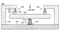
- FIG. 1 is a schematic cross-sectional view of the stage apparatus 101.
- the stage apparatus 101 includes a base 110, an urging unit 120, a moving stage 130, and a vibration actuator unit 201.
- the urging unit 120 and the vibration actuator unit 201 are arranged on the upper surface of the flat base 110.
- the vibration actuator unit 201 is fixed to the upper surface of the base 110 by the fixing portion 112.
- the moving stage 130 is supported from below by the vibration actuator unit 201.
- the urging unit 120 includes a support 122, an elastic member 124, a spherical seat 126, and a rolling ball 128.
- the support column 122 extends upward in the drawing from the upper surface of the base 110, and further extends laterally and is extended upward in the drawing of the moving stage 130.
- An elastic member 124, a spherical seat 126 and a rolling ball 128 are stacked between the tip of the support column 122 and the upper surface of the moving stage 130.
- the rolling ball 128 contacts the upper surface of the moving stage 130.
- the spherical seat 126 prevents the rolling ball 128 from being displaced on the surface of the moving stage 130 while allowing the rolling ball 128 to roll.
- the elastic member 124 is sandwiched between the support 122 and the spherical seat 126 in a compressed state. As a result, the spherical seat 126 and the rolling ball 128 are pressed downward from the upper end of the column 122.
- the urging units 120 as described above are provided at a plurality of locations on the moving stage 130 and cooperate to urge the moving stage 130 downward, in other words, in a direction approaching the base 110. Since the moving stage 130 is supported from below by the vibration actuator unit 201, the contact portion 210 disposed on the upper end of the vibration actuator unit 201 is pressed toward the lower surface of the moving stage 130.
- the structure of the urging unit 120 is not limited to the illustrated example.
- the urging unit 120 is provided for the purpose of maintaining a state in which the abutting portion 210 of the vibration actuator unit 201 and the driven surface of the movable stage 130 to be driven are in contact with each other.
- An urging unit 120 that generates an urging force using another method such as fluid pressure may be provided.
- FIG. 2 is a schematic exploded perspective view of the vibration actuator unit 201.
- the vibration actuator unit 201 includes a contact portion 210, a piezoelectric body 220, a common electrode 235, and a plurality of individual electrodes 231, 232, 233, and 234.
- the abutting portion 210 is fixed to the upper surface of the piezoelectric body 220 in the drawing, protrudes from the surface of the piezoelectric body 220, and contacts the lower surface of the moving stage 130 in the drawing.
- the contact portion 210 vibrates together with the piezoelectric body 220.
- the piezoelectric body 220 is formed of a piezoelectric material such as PZT.
- the piezoelectric material expands and contracts in a previously polarized direction when a voltage is applied.
- polarization is performed so that the direction indicated by the arrow Z in the figure is the polarization axis direction. Therefore, when a driving voltage whose voltage value changes periodically is applied, the piezoelectric body 220 generates mechanical vibration that expands and contracts in the direction indicated by the arrow Z in the drawing.
- the individual electrodes 231, 232, 233, 234 and the common electrode are formed of a conductive material such as metal and are insulated from each other.
- the common electrode 235 has substantially the same area as the adjacent piezoelectric body 220 and is coupled to a reference potential, for example, a ground potential. In other words, the entire piezoelectric body 220 is divided into two blocks by the common electrode 235.
- the individual electrodes 231, 232, 233, and 234 are disposed at positions facing the common electrode 235 with the piezoelectric body 220 interposed therebetween.
- a plurality of piezoelectric material blocks 221, 222, 223, and 224 sandwiched between any of the individual electrodes 231, 232, 233, and 234 and the common electrode 235 are formed on the piezoelectric body 220.
- the individual electrodes 231, 232, 233 and 234 are arranged along the arrangement direction of the piezoelectric material blocks 221, 222, 223 and 224.
- the piezoelectric body 220 and the individual electrodes 231, 232, 233, and 234 form an electromechanical transducer that converts electrical vibration of the applied drive voltage into mechanical vibration.
- the contact portion 210, the piezoelectric body 220, the individual electrodes 231, 232, 233, and 234 and the common electrode 235 are in close contact with each other.
- Such a vibration actuator unit 201 is not necessarily manufactured by combining components having the illustrated shape.
- the same structure as the illustrated vibration actuator unit 201 can be formed by sequentially laminating a piezoelectric material and a conductive material, each of which is layered.
- each electrode 231, 232, 233, 234 and the common electrode 235 are arranged on a plane parallel to the arrow Y in the drawing.
- each electrode can be disposed on the other surface or the corner of the piezoelectric body 220.
- the piezoelectric body 220 can be formed in a cylindrical shape, and electrodes can be disposed on the inner surface thereof.
- FIG. 3 is a schematic side view of the vibration actuator unit 201.
- FIG. 3 shows a state where the vibration actuator unit 201 is viewed from the direction indicated by the arrow X in FIGS. 1 and 2, that is, the direction orthogonal to some of the individual electrodes 231 and 232. Elements that are the same as those in FIG. 2 are given the same reference numerals, and redundant descriptions are omitted.
- the individual electrodes 231 and 232 are arranged by dividing the piezoelectric body 220 into left and right in the drawing. Temporarily, the B phase drive signal applied to the individual electrode 232 located on the left side in the figure and the C phase drive signal applied to the individual electrode 233 located behind the individual electrode 232 across the piezoelectric body 220 have the same phase. The voltage is changed periodically. In addition, the A phase drive signal applied to the individual electrode 231 located on the right side in the figure and the D phase drive signal applied to the individual electrode 234 located behind the individual electrode 231 with the piezoelectric body 220 interposed therebetween have the same phase. The voltage is assumed to change periodically.
- FIG. 4 is a diagram illustrating an example of a drive signal waveform supplied to the vibration actuator unit 201. As illustrated, the A-phase drive signal and the D-phase drive signal are synchronized with each other. The B phase drive signal and the C phase drive signal are also synchronized with each other. The A-phase drive signal and the D-phase drive signal have phases advanced by 90 ° with respect to the B-phase drive signal and the C-phase drive signal.
- FIG. 5 is a schematic diagram for explaining the operation of the vibration actuator unit 201 when a drive signal having the above combination is applied to the vibration actuator unit 201. Elements that are the same as those in FIG. 3 are given the same reference numerals, and redundant descriptions are omitted.
- the voltage of the A-phase drive signal and the D-phase drive signal is the same as that of the B-phase drive signal and the C-phase drive signal during the period where the phase of the A-phase drive signal is from 0 to 135 ° and the period of 315 ° or more. Higher than voltage.
- the piezoelectric material blocks 221 and 224 are relatively longer than the piezoelectric material blocks 222 and 223, and the piezoelectric body 220 has a contact portion 210 at the upper end on the right side in the drawing. Bend to displace toward.
- the piezoelectric material blocks 222 and 223 are relatively longer than the piezoelectric material blocks 221 and 224, and the piezoelectric body 220 is bent so that the contact portion 210 at the upper end is displaced to the left in the drawing. To do.
- the voltage values of all the drive signals are positive during the period in which the phase of the A-phase drive signal is 90 ° to 180 °.
- the voltage values of all the drive signals are negative. Therefore, the length of the entire piezoelectric body 220 is relatively larger in the former period than in the latter period.
- FIG. 6 is a schematic side view of the vibration actuator unit 201.
- FIG. 6 shows a state where the vibration actuator unit 201 is viewed from the direction indicated by the arrow Y in FIGS. 1 and 2, that is, the surface direction of the individual electrodes 231 and 234 and the common electrode 235. Elements that are the same as those in FIG. 2 are given the same reference numerals, and redundant descriptions are omitted.
- the individual electrodes 231 and 234 sandwich the piezoelectric body 220 between the common electrode 235 and the individual electrodes 231 and 234, respectively.
- the A-phase drive signal applied to the individual electrode 231 located on the left side in the drawing and the B-phase drive signal applied to the individual electrode 232 adjacent to the individual electrode 231 periodically change in voltage with the same phase.
- the D-phase drive signal applied to the individual electrode 234 located on the right side in the drawing and the C-phase drive signal applied to the individual electrode 233 adjacent to the individual electrode 234 periodically change the voltage with the same phase.
- FIG. 7 is a diagram illustrating an example of a drive signal waveform supplied to the vibration actuator unit 201.
- the A-phase drive signal and the B-phase drive signal are synchronized with each other.
- the D-phase drive signal and the C-phase drive signal are also synchronized with each other.
- the A-phase drive signal and the B-phase drive signal have phases advanced by 90 ° with respect to the D-phase drive signal and the C-phase drive signal.
- FIG. 8 is a schematic diagram for explaining the operation of the vibration actuator unit 201 when a drive signal having the above combination is applied to the vibration actuator unit 201. Elements that are the same as those in FIG. 6 are given the same reference numerals, and redundant descriptions are omitted.
- the voltage of the A-phase drive signal and the B-phase drive signal is the same as that of the D-phase drive signal and the C-phase drive signal during the period from 0 to 135 ° and the phase of 315 ° or more. Higher than voltage.
- the piezoelectric material blocks 221 and 222 are relatively longer than the piezoelectric material blocks 224 and 223, and the piezoelectric body 220 has a contact portion 210 at the upper end on the left side in the figure. Bend to displace.
- the piezoelectric material blocks 221 and 222 are relatively longer than the piezoelectric material blocks 224 and 223, and the piezoelectric body 220 is bent so as to displace the contact portion 210 at the upper end to the right in the drawing. To do.
- the voltage values of all the drive signals are positive.
- the voltage values of all the drive signals are negative. Therefore, the length of the entire piezoelectric body 220 is relatively larger in the former period than in the latter period.
- the vibration actuator unit 201 can move the moving stage 130 in the direction of the arrow X and the direction of the arrow Y. Further, a drive signal in which the drive signal shown in FIG. 4 and the drive signal shown in FIG. 7 are superimposed is added to the vibration actuator unit 201, so that the direction of the arrow X and the direction of the arrow Y are combined. Also, the moving stage 130 can be moved.
- the vibration actuator unit 201 is a single actuator, the moving stage 130 can be moved two-dimensionally by changing the combination of drive signals. 1 shows a single vibration actuator unit 201, it goes without saying that a plurality of vibration actuator units 201 may be provided.
- FIG. 9 is a schematic cross-sectional view of the stage apparatus 102.
- the stage apparatus 102 has the same structure as the stage apparatus 101 shown in FIG. 1 except for the parts described below. Therefore, common elements are denoted by the same reference numerals as those of the stage apparatus 101, and redundant description is omitted.
- the stage apparatus 102 differs from the stage apparatus 101 in that it includes a vibration actuator unit 202.
- the vibration actuator unit 202 has a single support portion 114 projecting downward on the lower surface in the drawing.
- the support part 114 abuts on the upper surface of the base 110 and supports and fixes the vibration actuator unit 202 at a single point.
- the vibration actuator unit 202 has a pair of contact portions 210 on the upper surface in the drawing.
- the point that the moving stage 130 is urged downward by the urging unit 120 is the same as that of the vibration actuator unit 201.
- each of the pair of contact portions 210 contacts the lower surface of the moving stage 130 and supports the moving stage 130 from below.
- FIG. 10 is a schematic exploded perspective view of the vibration actuator unit 202.
- the vibration actuator unit 202 includes a pair of contact portions 210, a piezoelectric body divided into a plurality of piezoelectric material blocks 221, 222, 223, and 224, a common electrode 235, and a plurality of individual electrodes 231, 232, 233, and 234, respectively.
- the piezoelectric material blocks 221, 222, 223, and 224 are all polarized in the longitudinal direction, that is, in the direction shown by the arrow X in the drawing in the state shown in FIG.
- a left wing block 228 corresponding to the left half in the figure is separated by individual electrodes 231 and 232 and a common electrode 235 arranged horizontally in the figure, and a pair of piezoelectric elements arranged vertically in the figure.
- Material blocks 221 and 222 are formed.
- the individual electrodes 231 and 232 are arranged in the arrangement direction of the piezoelectric material blocks 221 and 222.
- a right wing block 229 corresponding to the right half in the figure is divided by individual electrodes 233 and 234 and a common electrode 235 arranged vertically in the figure, and a pair arranged horizontally in the figure.
- the piezoelectric material blocks 223 and 224 are formed.
- the individual electrodes 233 and 234 are arranged in the arrangement direction of the piezoelectric material blocks 223 and 224.
- the left wing block 228 of the vibration actuator unit 202 bends in a plane perpendicular to the surface of the base 110 in the stage device 102.
- the right wing block 229 of the vibration actuator unit 202 causes mechanical vibration that bends in a plane parallel to the surface of the base 110 in the stage device 102. Arise.
- One of the pair of abutting portions 210 is arranged at the approximate center in the surface direction in the individual electrode 231 located on the upper surface of the left wing block 228.
- the other abutting portion 210 is disposed at the approximate center of the upper surface formed when the individual electrodes 233 and 234, the piezoelectric material blocks 223 and 224, and the common electrode 235 of the right wing block 229 are brought into close contact with each other.
- These contact portions 210 vibrate together when either the piezoelectric material blocks 221 and 222 or the piezoelectric material blocks 223 and 224 vibrate, respectively.
- the vibration actuator unit 202 in use is in a state in which the illustrated abutting portion 210, piezoelectric material blocks 221, 222, 223, 224, individual electrodes 231, 232, 233, 234 and common electrode 235 are in close contact with each other. is there.
- Such a vibration actuator unit 202 is not necessarily manufactured by combining components having the illustrated shape.
- the same structure as the illustrated vibration actuator unit 201 can be formed by sequentially laminating a piezoelectric material and a conductive material, each of which is layered.
- the support portion 114 and the contact portion may be adhered and attached.
- a poticon (trade name) having little deformation and wear resistance can be used.
- FIG. 11 is a diagram showing drive signal waveforms applied to the individual electrodes 231, 232, 233 and 234 of the vibration actuator unit 202.
- the individual electrode 231 has an A phase drive signal
- the individual electrode 232 has a B phase drive signal
- the individual electrode 233 has a C phase drive signal
- the individual electrode 234 has a D phase. It is assumed that the drive signals are individually applied.
- the A-phase drive signal and the B-phase drive signal are 180 ° out of phase and have inverted signal waveforms.
- the piezoelectric material blocks 221 and 222 in the vibration actuator unit 202 are within the plane orthogonal to the upper surface of the base 110 of the stage device 102 as described above. A bending mechanical vibration is generated.
- the C-phase driving signal and the D-phase driving signal are synchronized with each other and have the same signal waveform.
- the piezoelectric material blocks 223 and 224 in the vibration actuator unit 202 expand and contract integrally.
- the expansion / contraction direction of the piezoelectric material blocks 223 and 224 is the direction indicated by the arrow X in FIGS.
- the vibration actuator unit 202 causes the moving stage 130 to move in the stage apparatus 102. It is moved in the direction indicated by arrow X in the figure.
- the moving direction of the moving stage 130 is reversed.
- FIG. 12 is a diagram showing other drive signal waveforms applied to the individual electrodes 231, 232, 233, 234 of the vibration actuator unit 202.
- the A-phase drive signal and the B-phase drive signal are 180 ° out of phase and have inverted signal waveforms. Therefore, as described above, the piezoelectric material blocks 221 and 222 generate mechanical vibration that bends in a plane orthogonal to the upper surface of the base 110 of the stage apparatus 102.
- the C-phase drive signal and the D-phase drive signal also have signal waveforms that are inverted from each other with a phase shift of 180 °. Therefore, the piezoelectric material blocks 223 and 224 generate mechanical vibration that bends in a plane parallel to the surface of the base 110 of the stage apparatus 102.
- the vibration actuator unit 202 causes the stage 130 to move the moving stage 130. , In the direction opposite to the direction indicated by the arrow Y in the figure.
- the moving direction of the moving stage 130 is reversed.
- the vibration actuator unit 202 can move the moving stage 130 in the direction of the arrow X and the direction of the arrow Y. Furthermore, the moving direction of the moving stage 130 can be changed by variously changing the delay relationship between the driving signals from the A phase to the D phase.
- the vibration actuator unit 202 is a single actuator, the moving stage 130 can be moved two-dimensionally by changing the combination of drive signals.
- a single vibration actuator unit 201 is provided in the stage apparatus 102 in FIG. 9, it goes without saying that a plurality of vibration actuator units 202 may be provided according to an assumed load.
- FIG. 13 is a schematic cross-sectional view of the stage apparatus 103.
- the stage apparatus 103 has the same structure as the stage apparatus 102 shown in FIG. 9 except for the parts described below. Therefore, the same reference numerals as those of the stage apparatus 102 are assigned to the common elements, and redundant description is omitted.
- the stage apparatus 102 differs from the stage apparatus 102 in that it includes a vibration actuator unit 203.
- the vibration actuator unit 203 is different from the vibration actuator unit 202 in the arrangement of the piezoelectric material blocks 221, 222, 223 and 224 formed by the individual electrodes 231, 232, 233 and 234 and the common electrode 235.
- FIG. 14 is a schematic exploded perspective view of the vibration actuator unit 203.
- the vibration actuator unit 203 includes a pair of contact portions 210, a piezoelectric body 220 divided into a plurality of piezoelectric material blocks, a common electrode 235, and a plurality of individual electrodes 231, 232, 233, and 234, respectively.
- the piezoelectric material blocks 221, 222, 223, and 224 are all polarized in the longitudinal direction, that is, in the direction shown by the arrow X in the drawing in the state shown in FIG.
- the piezoelectric body 220 is divided into a pair of piezoelectric bodies 220 arranged in a direction perpendicular to the longitudinal direction by a common electrode 235 arranged in the longitudinal direction. Furthermore, four individual electrodes 231, 232, 233, and 234 that divide the surface into four parts vertically and horizontally are disposed on the surface facing the common electrode 235 in each of the pair of piezoelectric bodies 220.
- each of the eight piezoelectric material blocks 221, 222, 223, and 224 includes one apex of the piezoelectric body 220 that forms a hexahedron as a whole.
- a pair having the same reference number is arranged at diagonal positions of the piezoelectric body 220 that forms a hexahedron as a whole, and has the same phase drive signal in common. To receive.
- the left wing block 228 corresponding to the left half in the drawing and the right wing block 229 corresponding to the right half in the drawing each operate similar to the vibration actuator unit 201 shown in FIG. .
- these blocks are coupled in a state of being rotated around a common rotation axis in the longitudinal direction of the piezoelectric body 220, the behavior of the left half in the figure and the right half in the figure is different. Arise.
- the vibration actuator unit 203 the amplitude of vibration generated in the piezoelectric body 220 when a drive signal is supplied is increased. Therefore, in the stage apparatus 103, the moving stage 130 is driven efficiently.
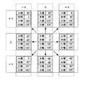
- FIG. 15 is a diagram showing a phase relationship of drive signals applied to the individual electrodes 231, 232, 233, and 234 of the vibration actuator unit 203.
- the symbols X and Y described in the upper and left columns indicate the moving direction of the moving stage 130 driven by the vibration actuator unit 203 corresponding to the arrows X and Y shown in FIG. 13. Show.
- the moving direction of the moving stage 130 can be changed by variously changing the delay relationship between the driving signals from the A phase to the D phase.
- the vibration actuator unit 203 drives the eight piezoelectric material blocks 221, 222, 223, and 224 with four-phase driving signals, thereby moving the moving stage 130. It can be moved both in the direction of arrow X and in the direction of arrow Y. Further, the moving direction of the moving stage 130 can be changed by changing the phase delay relationship between the drive signals.
- the vibration actuator unit 203 is a single actuator, the moving stage 130 can be moved two-dimensionally by changing the combination of drive signals.
- the stage apparatus 102 of FIG. 9 is provided with a single vibration actuator unit 203, a plurality of vibration actuator units 203 may be provided according to an assumed load.
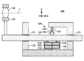
- FIG. 16 is a schematic cross-sectional view of the optical device 104.
- the optical device 104 includes a vibration actuator unit 203.
- the same reference numerals are assigned to elements common to the stage apparatus 103 shown in FIG.
- the optical device 104 has a unique structure in that it includes a moving shaft 132 instead of the moving stage 130 in the stage device 102.
- the moving shaft 132 is inserted through a bearing portion 121 provided on the support column 122 and supported from the base 110 so as to be slidable in the direction indicated by an arrow X in the drawing. Further, the moving shaft 132 is supported by the bearing portion 121 so as to be rotatable around the central axis in the longitudinal direction.
- the moving shaft 132 holds a lens 136 constituting a part of the optical system in a holding frame 134 attached to one end on the outer side of the base 110. Therefore, the lens 136 moves along the optical axis L parallel to the central axis of the moving shaft 132 when the moving shaft 132 slides in the longitudinal direction.
- FIG. 17 is a schematic perspective view of the optical device 104. Elements that are the same as those in FIG. 16 are given the same reference numerals, and redundant descriptions are omitted. FIG. 17 is drawn with the base 110 and the support column 122 omitted.
- the abutting portion 210 of the vibration actuator unit 203 abuts on the cylindrical peripheral surface of the moving shaft 132 to transmit the driving force. Therefore, when the vibration actuator unit 203 generates a driving force in the direction of the arrow X shown in FIG. 16, the moving shaft 132 moves in the direction of its own central axis.
- the moving shaft 132 when the vibration actuator unit 203 generates a driving force in the direction of the arrow Y shown in FIG. 16, the moving shaft 132 has its own central axis as shown by the arrow Q in FIG. Rotate around. When the moving shaft 132 rotates, the lens 136 deviates from the optical axis L.
- the lens 136 which is an optical member, can be moved in a direction away from the optical axis L in addition to the optical axis L direction. Therefore, in addition to moving the lens 136 to change the characteristics of the optical system, the optical configuration itself can be changed by removing the lens 136 from the optical system.
- the optical device 104 is formed using the vibration actuator unit 203.
- the optical device 104 may be formed using the other vibration actuator units 201 and 202 already described.
- FIG. 18 is a schematic cross-sectional view of the optical device 105, and shows a cross section orthogonal to the optical axis L of the optical system including the lens 136. Elements that are the same as those in FIG. 17 are given the same reference numerals, and redundant descriptions are omitted.
- the optical device 105 includes a lens barrel 116, leaf springs 125 and 127, a holding frame 134, a lens 136, and a vibration actuator unit 203.
- a holding frame 134 that holds the lens 136 is coupled to a pair of leaf springs 125 and 127.
- Each vibration actuator unit 203 has the same structure as the vibration actuator unit 203 already described, and can move with respect to the inner surface of the lens barrel 116 in a direction perpendicular to the paper surface and a direction parallel to the paper surface. .
- the pair of leaf springs 125 and 127 are biased in the extending direction, and the respective end portions press the vibration actuator unit 203 toward the inner surface of the lens barrel 116.
- the holding frame 134 and the lens 136 are held at substantially the center of the lens barrel 116 in the drawing.
- the inclination of the lens 136 with respect to the optical axis L changes.
- the lens 136 translates in the direction of the optical axis L while maintaining an angle with respect to the optical axis L.
- the lens 136 moves in parallel with the paper surface as indicated by an arrow X in the figure while maintaining the inclination with respect to the optical axis L.
- FIG. 19 is a schematic cross-sectional view for explaining another operation of the optical device 105 shown in FIG. Elements that are the same as those in FIG. 18 are given the same reference numerals, and redundant descriptions are omitted.
- the pair of the vibration actuator unit 203 disposed on the lower side in the figure, as indicated by the arrow M 2 in the figure, moves in parallel to the paper surface in a direction away from each other.
- the vibration actuator unit 203 By the operation of the vibration actuator unit 203 as described above, the upper portions of the leaf springs 125 and 127 in the drawing approach to be parallel to the side surface of the lens barrel 116.
- the lower part of the leaf springs 125 and 127 in the figure has a large inclination with respect to the side surface of the lens barrel 116.
- the lens 136 as shown by arrow M 3 in the figure, translates towards the position of the lower in the lens barrel 116.
- the vibration actuator unit 203 on the upper side in the figure and the vibration actuator unit 203 on the lower side in the figure perform different operations, so that the lens 136 can be moved up and down in the figure. Furthermore, by combining the operations of the vibration actuator unit 203, the optical adjustment of the lens 136 can be executed by electrical control with respect to the vibration actuator unit 203.
- the optical device 105 is formed using the vibration actuator unit 203.
- the optical device 105 may be formed using the other vibration actuator units 201 and 202 already described.
- FIG. 20 is a schematic perspective view of the active rotary joint device 106.
- the active rotary joint device 106 includes a base 110, an urging unit 120, a driven sphere 138, and a vibration actuator unit 203.
- the vibration actuator unit 203 is fixed to the base 110 by bringing the support portion 114 into contact with the upper surface of the base 110.
- the driven sphere 138 comes into contact with the contact portion 210 of the vibration actuator unit 203 and is supported and fixed from below in the figure.
- the urging unit 120 includes a column 122 extending upward in the drawing from the base 110, an elastic member 124 suspended from the column 122, and a spherical seat 126 urged downward by the elastic member 124. .
- the spherical seat 126 urges the driven sphere 138 downward. Therefore, the driven sphere 138 is pressed against the contact portion 210 of the vibration actuator unit 203.
- the vibration actuator unit 203 When the vibration actuator unit 203 operates in the active rotary joint device 106 as described above, the driven sphere 138 rotates while maintaining the same position. Thereby, the movable limb 139 attached to the driven sphere 138 changes the inclination with respect to the base 110.
- the vibration actuator unit 203 generates a driving force in an arbitrary direction with respect to the surface direction of the base 110. Therefore, the active rotary joint device 106 can change the inclination of the movable limb 139 by electrical control of the driving power supplied to the vibration actuator unit 203.
- the active rotary joint device 106 is formed using the vibration actuator unit 203.
- the active rotary joint device 106 may be formed using the other vibration actuator units 201 and 202 already described.
- FIG. 21 is a schematic sectional view of the camera system 500.
- the camera system 500 includes a lens unit 600 and a camera body 300.
- the side on which the object to be imaged of the camera system 500 is located is described as the front side or the front end side.
- the side on which the camera body 300 is disposed with respect to the lens unit 600 is referred to as a rear side or a back side.
- the lens unit 600 includes a fixed cylinder 610, lens groups 620, 630, and 640, a lens side control unit 650, and a vibration actuator unit 400.
- a lens side mount portion 660 is provided at the rear end of the fixed cylinder 610.
- the lens side mount portion 660 is fitted with the body side mount portion 360 of the camera body 300 to couple the lens unit 600 to the camera body 300. Since the coupling between the lens side mount portion 660 and the body side mount portion 360 can be released, the lens unit 600 can be replaced with another lens unit 600 having the lens side mount portion 660 of the same standard.
- the lens groups 620, 630, and 640 are arranged along the optical axis X inside the fixed cylinder 610 to form an optical system. At least one lens group 630 is supported by a holding frame 632 having a fitting portion 634 and an engaging portion 636.
- the fitting portion 634 is fitted to the guide shaft 612. Further, the engaging portion 636 engages with the guide shaft 612.
- the guide shaft 612 is arranged in parallel with the optical axis X of the optical system and is fixed to the fixed cylinder 610. Therefore, the holding frame 632 is slidably supported along the guide shaft 612.
- the holding frame 632 is integrally coupled to the vibration actuator unit 400.
- the vibration actuator unit 400 includes an urging unit 410 and an electromechanical conversion element 420.
- the urging unit 410 presses the electromechanical conversion element 420 toward the guide shaft 612.
- the electromechanical transducer 420 generates vibration by the supplied driving power and generates a driving force that moves the holding frame 632 along the guide shaft 612.
- a magnetic sensor 430 disposed to face the vibration actuator unit 400 is fixed to the inner surface of the fixed cylinder 610.
- the magnetic sensor 430 is used when detecting the positions of the urging unit 410 and the electromechanical transducer 420.
- the lens side control unit 650 includes a drive circuit that outputs the drive power of the vibration actuator unit 400 and controls the entire lens unit 600.
- the lens side control unit 650 is also responsible for communication between the body side control unit 322 mounted on the camera body 300 and the lens unit 600 side. Thereby, the lens unit 600 attached to the camera body 300 operates in cooperation with the camera body 300.
- the camera body 300 includes a mirror unit 370 on the rear side of the body side mount portion 360.
- the mirror unit 370 has a main mirror holding frame 372 and a main mirror 371.
- the main mirror holding frame 372 is supported by a main mirror rotating shaft 373 while holding the main mirror 371.
- the mirror unit 370 has a sub mirror holding frame 375 and a sub mirror 374.
- the sub mirror holding frame 375 is pivotally supported from the main mirror holding frame 372 by a sub mirror rotating shaft 376 while holding the sub mirror 374.
- the sub mirror 374 and the sub mirror holding frame 375 rotate with respect to the main mirror holding frame 372 while moving together with the main mirror holding frame 372.
- a focusing screen 352 and a pentaprism 354 are sequentially arranged above the mirror unit 370 in the drawing.
- a finder optical system 356 and a photometric sensor 390 are disposed behind the pentaprism 354 in the drawing.
- the rear end of the viewfinder optical system 356 is exposed as a viewfinder 350 on the back surface of the camera body 300.
- the photometric sensor 390 detects the intensity of incident light.
- a focal plane shutter 310 In the camera body 300, a focal plane shutter 310, an optical filter 332, and an image sensor 330 are sequentially arranged behind the mirror unit 370 in the drawing.
- the focal plane shutter 310 opens and closes to open or shield the image sensor 330 against incident light.
- the optical filter 332 is installed immediately before the image sensor 330 and removes infrared rays and ultraviolet rays from the light incident on the image sensor 330.
- the optical filter 332 protects the surface of the image sensor 330.
- the optical filter 332 includes a low-pass filter that reduces the spatial frequency of the incident light. Thereby, the optical filter 332 removes the spatial frequency component exceeding the Nyquist frequency of the image sensor 330 from the incident light, and suppresses the generation of moire.
- the imaging element 330 is formed by a photoelectric conversion element such as a CCD sensor or a CMOS sensor, and receives incident light that has passed through the optical filter 332.
- a substrate 320 and a rear display unit 340 are sequentially arranged behind the image sensor 330.
- a body side control unit 322, an image processing unit 324, and the like are mounted on the substrate 320.
- the rear display unit 340 is formed of a liquid crystal display panel or the like, and is exposed on the rear surface of the camera body 300.
- the main mirror 371 in the state shown in the figure is at an observation position that obliquely crosses the light incident through the lens unit 600.
- the main mirror 371 has a reflection region that reflects incident light and a half mirror region that transmits part of the incident light.
- Part of the subject light incident on the main mirror 371 at the observation position passes through the half mirror region and enters the sub mirror 374.
- the sub mirror 374 reflects the incident light downward in the figure, and makes the incident light enter the focus sensor 382 through the focusing optical system 380 arranged in the lower part of the mirror unit 370 in the figure.
- the reflection region of the main mirror 371 at the observation position reflects the light incident through the lens unit 600 toward the focusing screen 352.
- the focusing screen 352 is disposed at a position optically conjugate with the element arrangement surface of the image sensor 330 and visualizes an image formed by the optical system of the lens unit 600.
- the subject image connected to the focusing screen 352 is observed as an erect image from the viewfinder 350 through the pentaprism 354 and the viewfinder optical system 356.
- the photometric sensor 390 disposed above the finder optical system 356.
- the photometric sensor 390 detects the light intensity of the received light.
- the body-side control unit 322 calculates subject brightness according to the detected light intensity, and calculates imaging conditions such as an aperture value, shutter speed, and ISO sensitivity according to the calculated subject brightness. As a result, the camera system 500 is in a state where it can shoot a subject under appropriate shooting conditions.
- the focus sensor 382 detects the defocus amount in the optical system of the lens unit 600 and notifies the body side control unit 322 of it.
- the body-side control unit 322 calculates a movement amount of the lens group 630 sufficient to cancel the detected defocus amount, and notifies the lens-side control unit 650 of the movement amount.
- the lens-side control unit 650 drives the lens group 630 by operating the vibration actuator unit 400 according to the notified movement amount. As a result, the subject image formed by the optical system of the lens unit 600 becomes clear on the focusing screen 352.
- the main mirror holding frame 372 rotates clockwise together with the main mirror 371 in the drawing and stops substantially horizontally at the shooting position. As a result, the main mirror 371 retracts from the optical path of the incident light through the optical system of the lens unit 600.
- the sub mirror holding frame 375 When the main mirror 371 rotates toward the shooting position, the sub mirror holding frame 375 also moves up with the main mirror holding frame 372 and rotates around the sub mirror rotation shaft 376 and stops substantially horizontally at the shooting position. To do. As a result, the sub mirror 374 is also retracted from the optical path of the incident light.
- the front curtain of the focal plane shutter 310 is subsequently opened. Thereby, the light incident through the optical system of the lens unit 600 passes through the optical filter 332 and is received by the image sensor 330 and imaged. Thereafter, the rear film of the focal plane shutter 310 is closed, the main mirror 371 and the sub mirror 374 are returned to the observation position again, and a series of operations related to photographing is completed.
- the vibration actuator unit 400 is applied to the lens unit 600 in the camera system 500 of the interchangeable lens single-lens reflex camera. It can be used for the purpose of moving the optical member in the lens unit of the apparatus.
- the present invention is not limited to the imaging device, and can be widely used when driving a member positioned with high positioning accuracy, including an optical device such as a microscope provided with an optical member.
- the present invention is not limited to optical devices, and can be widely used as actuators for stage devices and the like.
- FIG. 22 is a cross-sectional view schematically showing a cross section orthogonal to the optical axis X of the lens unit 600. Elements that are the same as those in FIG. 21 are given the same reference numerals, and redundant descriptions are omitted.
- the holding frame 632 that holds the lens group 630 is integrally provided with a fitting portion 634 at the upper end in the drawing.
- the fitting portion 634 surrounds the guide shaft 612 together with the electromechanical conversion element 420. Thereby, the holding frame 632 is fitted to the guide shaft 612 in a state where the holding frame 632 can rotate around the guide shaft 612.
- the holding frame 632 is integrally provided with an engaging portion 636 at the lower end in the drawing.
- the engaging portion 636 has parallel surfaces with substantially the same interval as the outer diameter of the guide shaft 612, and sandwiches the guide shaft 612 between the parallel surfaces. Thereby, the lower side of the holding frame 632 is prevented from being displaced parallel to the paper surface and horizontally in the drawing. Therefore, the holding frame 632 is positioned in the direction parallel to the paper surface by the fitting portion 634 and the engaging portion 636.
- the magnetic sensor 430 is fixed to the inner surface of the fixed cylinder 610 so as to face the upper surface of the urging portion 410.
- the urging unit 410 moves along with the holding frame 632 perpendicular to the paper surface. Therefore, the magnetic sensor 430 and the urging unit 410 do not necessarily face each other at the same position in the direction perpendicular to the paper surface.
- FIG. 23 is a schematic diagram showing the overall structure of the vibration actuator unit 400. Elements common to FIGS. 21 and 22 are denoted by the same reference numerals, and redundant description is omitted.
- the vibration actuator unit 400 includes an urging unit 410, an electromechanical conversion element 420, and a magnetic sensor 430.
- the vibration actuator unit 400 in the lens unit 600 is supplied with driving power from the lens-side control unit 650 and operates under the control of the lens-side control unit 650.
- the electromechanical transducer 420 has a support part 422, a contact part 424 and a piezoelectric body 425.
- the piezoelectric body 425 is formed of a rectangular parallelepiped piezoelectric material.
- the pair of contact portions 424 are arranged on the lower surface of the piezoelectric body 425 in the drawing and are in contact with the guide shafts 612, respectively.
- the support portion 422 is disposed on the upper surface of the piezoelectric body 425 in the drawing.
- the support portion 422 contacts the urging portion 410 from below in the drawing and receives the urging force from the urging portion 410.
- the electromechanical conversion element 420 is urged downward in the figure, and the contact portion 424 is pressed toward the guide shaft 612.
- the urging unit 410 includes a permanent magnet 412, a yoke 414, and a buffer member 416.
- the yoke 414 is made of a magnetic material and is disposed along the side surface from the upper surface of the electromechanical transducer 420 in the drawing. The lower end of the yoke 414 approaches the guide shaft 612 but does not contact it.
- the permanent magnet 412 is placed on the yoke 414 so that the magnetic poles are arranged in a direction parallel to the guide shaft 612. Therefore, the yoke 414 is also magnetized by the permanent magnet 412.
- the guide shaft 612 is also formed of a magnetic material and forms a part of the urging portion 410. That is, the magnetic field generated by the permanent magnet 412 forms a magnetic circuit by the yoke 414 and the guide shaft 612 that are each a magnetic material. Thereby, the urging portion 410 is attracted toward the guide shaft 612.
- the force that attracts the biasing portion 410 toward the guide shaft 612 is transmitted to the electromechanical transducer 420 as the biasing force through the support portion 422 as described above, and presses the contact portion 424 against the guide shaft 612.
- the electromechanical transducer 420 is preloaded toward the guide shaft 612 by the magnetic force generated by the permanent magnet 412.
- the buffer member 416 is attached to the lower end of the yoke 414, and prevents the guide shaft 612 from rubbing when the lower end of the yoke 414 contacts the guide shaft 612 for some reason. Further, by forming the buffer member 416 with a non-magnetic material, it is possible to prevent the buffer member 416 from sticking to the guide shaft 612 when it contacts the guide shaft 612. Considering these functions, the buffer member 416 is preferably formed using a resin material having elasticity and lubricity, such as POM resin.
- the magnetic sensor 430 detects the magnetic force of the permanent magnet 412 of the urging unit 410 as a physical quantity. Therefore, when the urging unit 410 and the electromechanical transducer 420 are displaced with respect to the fixed cylinder 610, the magnetic sensor 430 detects a change in the magnetic field. Thereby, the lens side control unit 650 can know the position of the holding frame 632 based on the detection result of the magnetic sensor 430. Therefore, the lens-side control unit 650 can adjust the driving power supplied to the vibration actuator unit 400 according to the position of the holding frame 632.
- a Hall element As the magnetic sensor 430, a Hall element, a magnetic impedance element, or the like can be used. A plurality of magnetic sensors 430 may be arranged along the movement path of the vibration actuator unit 400.
- the urging unit 410 has a single permanent magnet 412, but a plurality of permanent magnets 412 may be arranged on the yoke 414. Thereby, a periodic change in the magnetic flux density is detected in the magnetic sensor 430, and the operation amount of the vibration actuator unit 400 can be detected with high accuracy.
- an electromagnet may be used instead of the permanent magnet 412. Since the electromagnet can change the strength of the generated magnetic force, the urging unit 410 using the electromagnet can change the urging force. However, when the magnetic force of the electromagnet is changed, it is preferable to correct the detection result of the magnetic sensor 430 in accordance with the change in the generated magnetic force.
- FIG. 24 is a schematic diagram showing a state in which one of the electromechanical transducer elements 420 is enlarged and viewed from the side. Elements that are the same as those in the other drawings are given the same reference numerals, and redundant descriptions are omitted.
- Each of the electromechanical conversion elements 420 has a pair of A-phase electrodes 421 and B-phase electrodes 423 arranged at diagonal positions of a piezoelectric body 425 that is substantially rectangular when viewed from the side.
- the piezoelectric body 425 is formed of a piezoelectric material such as PZT.
- the A-phase electrode 421 and the B-phase electrode 423 are each formed of a metal material fired together with the piezoelectric body 425.
- the piezoelectric body 425 may be formed by laminating layered piezoelectric materials, or may be in a bulk shape.
- the size of the piezoelectric body 425 formed in this way can be formed to be about 2 mm square by laminating, for example, about 10 layered piezoelectric materials.
- the A-phase electrode 421 and the B-phase electrode 423 are arranged at positions corresponding to the back surface of the piezoelectric body 425 in the direction perpendicular to the paper surface. Therefore, when a drive voltage is applied to the A-phase electrode 421, the piezoelectric body 425 contracts or expands in a region sandwiched between the A-phase electrodes 421. Similarly, when a drive voltage is applied to the B-phase electrode 423, the piezoelectric body 425 contracts or expands in a region sandwiched between the B-phase electrodes 423.
- FIG. 25 is a waveform diagram showing signal waveforms of the A-phase drive signal and the B-phase drive signal supplied to the electromechanical transducer 420.
- the A-phase drive signal and the B-phase drive signal fluctuate periodically.
- the B phase drive signal has a sine wave waveform that is 90 degrees behind the A device drive signal, that is, a cosine wave waveform.
- a voltage signal modulated by the modulation signal is generated as a B-phase drive signal.
- FIG. 26 is a schematic diagram showing the operation of the electromechanical transducer 420 supplied with the A-phase drive signal and the B-phase drive signal as described above. As described above, since the phase of the A-phase drive signal and the B-phase drive signal is shifted from each other, the piezoelectric body 425 is different in the region where the A-phase electrode 421 is disposed and the region where the B-phase electrode 423 is disposed. Extensive state.
- the electromechanical transducer 420 since the A-phase electrode 421 and the B-phase electrode 423 are disposed adjacent to each other, the electromechanical transducer 420 is deformed by bending due to the expansion and contraction of the piezoelectric body 425 as described above. In addition, the electromechanical conversion element 420 is also deformed to expand and contract in the longitudinal direction. As a result, as indicated by an arrow V in the drawing, the contact portion 424 generates an elliptical vibration that draws an elliptical activation in the drawing.
- the contact portion 424 of the electromechanical transducer 420 is pressed toward the guide shaft 612 by the biasing force applied by the biasing portion 410. Therefore, when the contact portion 424 generates the above elliptical vibration, the guide shaft 612 is displaced relative to the electromechanical conversion element 420.
- the contact portion 424 is preferably disposed at a portion corresponding to the antinode of vibration generated in the electromechanical conversion element 420.
- the vibration actuator unit 400 that moves integrally with the holding frame 632 is in contact with the guide shaft 612 at the contact portion 424 that generates the driving force, and is not in contact with other portions. Therefore, there is no place where sliding resistance is generated with the movement of the holding frame 632 driven by the vibration actuator unit 400, and the holding frame 632 can be driven smoothly.
- the drive amount of the vibration actuator unit 400 can be detected by detecting the magnetic flux density of the magnetic field generated by the permanent magnet 412 that is a part of the urging unit 410. Therefore, the operation amount of the vibration actuator unit 400 can be accurately detected without using expensive parts such as a linear scale that occupy a large space.
- the permanent magnet 412 is disposed on the yoke 414 that moves together with the piezoelectric body 425 side.
- the permanent magnet 412 may be disposed on the guide shaft 612 side, and the yoke 414 formed of a magnetic material may be attracted by a magnetic force to generate a biasing force.
- the magnetic sensor 430 is disposed on the piezoelectric body 425 side, and the operation amount of the vibration actuator unit 400 can be detected.
- FIG. 27 is a cross-sectional view of another lens unit 601 provided with the vibration actuator unit 400, and shows a cross section orthogonal to the optical axis X.
- FIG. Elements common to the embodiment shown up to FIG. 26 are denoted by the same reference numerals, and redundant description is omitted.
- the lens unit 601 includes a pair of vibration actuator units 400.
- the fixed cylinder 610 has a guide rail 611 formed integrally with the fixed cylinder 610 instead of the guide shaft 612.
- the guide rail 611 extends in a direction perpendicular to the paper surface, that is, in a direction parallel to the optical axis X of the lens unit 601 while maintaining a constant cross-sectional shape.
- the guide rail 611 forms a pair of flat guide surfaces 613 in the longitudinal direction of the lens unit 601.
- the pair of guide surfaces 613 have different inclinations with respect to the horizontal line in the drawing.
- Each of the pair of vibration actuator units 400 abuts against the pair of guide surfaces 613.
- the contact portion 424 is pressed against the guide surface 613 in different directions by the magnetic force generated by the permanent magnet 412 of the biasing portion 410. Therefore, the holding frame 632 is positioned with respect to the fixed cylinder 610 in any direction in the cross section shown in the figure by the pair of vibration actuator units 400 that generate the suction force with respect to the pair of guide surfaces 613. .
- the holding frame 632 and the fixed cylinder 610 are in contact with each other in the vibration actuator unit 400, and there is no other contact portion. Therefore, when the holding frame 632 is driven by the driving force of the vibration actuator unit 400, sliding resistance does not occur with the movement of the holding frame 632, and the holding frame 632 moves smoothly.
- each of the pair of vibration actuator units 400 can individually detect the movement amount by the magnetic sensor 430 with high accuracy. Therefore, the operation of the pair of vibration actuator units 400 can be synchronized, and the holding frame 632 can be moved without causing an inclination with respect to the optical axis X.
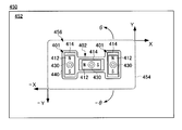
- FIG. 28 is a schematic plan view of a stage apparatus 450 provided with vibration actuator units 401 and 402.
- the stage device 450 includes a surface plate 452, a moving stage 454, and a drive unit 456.
- the moving stage 454 is disposed on a fixed surface plate 452 via a driving unit 456.
- the moving stage 454 is driven by the driving unit 456 and moves in the surface direction of the surface plate 452 with respect to the surface plate 452.
- the drive unit 456 includes a plurality of vibration actuator units 401 and 402.
- the individual structures of the vibration actuator units 401 and 402 are substantially the same as those of the vibration actuator unit 400 shown in FIG. However, each magnetic sensor 430 is embedded in the surface plate 452 at a position facing the permanent magnet 412.
- the pair of vibration actuator units 401 are arranged in parallel to the direction indicated by the arrow Y in the drawing.
- the other vibration actuator unit 402 is arranged in a direction orthogonal to the vibration actuator unit 401 as indicated by an arrow X in the drawing.
- These vibration actuator units 401 and 402 are integrally coupled by a connecting member 440 and further mounted with a moving stage 454. Accordingly, the moving stage 454 moves on the surface plate 452 together with the driving unit 456 in accordance with the operation of the driving unit 456.
- the pair of vibration actuator units 401 are operated synchronously to generate a driving force in the same direction, thereby moving the moving stage in the direction indicated by arrows Y and -Y in the drawing. 454 can be translated. Further, by moving another vibration actuator unit 402 to generate a driving force, the moving stage 454 can be translated in the direction indicated by the arrows X and -X in the drawing.
- stage apparatus 450 when the pair of vibration actuator units 401 are operated differently, the moving stage 454 can be rotated as indicated by arrows ⁇ and ⁇ in the drawing.
- the drive unit 456 by combining the plurality of vibration actuator units 401 and 402, a highly functional stage device 450 can be formed with a simple structure.
- FIG. 29 and 30 are schematic cross-sectional views of another stage device 451.
- FIG. 29 shows a cross section along the moving direction of the moving stage 454, and
- FIG. 30 shows a cross section orthogonal to the cross section of FIG.
- the stage device 451 includes a surface plate 452, a vibration actuator unit 403, and a moving stage 454.
- the moving stage 454 is supported by the vibration actuator unit 403 on a fixed surface plate 452. Accordingly, the moving stage 454 is driven by the vibration actuator unit 403 and moves relative to the surface plate 452 in the surface direction of the surface plate 452.
- the vibration actuator unit 403 includes an urging unit 410 and an electromechanical conversion element 420.
- the structure of the electromechanical transducer 420 is the same as that of the vibration actuator unit 400 shown in FIG. Accordingly, common reference numerals are assigned to the same elements, and redundant description is omitted.
- the urging unit 410 has a communication hole 411 that opens in the immediate vicinity of the surface plate 452.
- the communication hole 411 is coupled to a negative pressure source through the flexible tube 413. As a result, a negative pressure is also generated at the opening at the lower end of the communication hole 411 and the surface of the surface plate 452 is sucked.
- the urging unit 410 generates an urging force that presses the contact portion 424 of the electromechanical conversion element 420 against the surface plate 452, so that when the electromechanical conversion element 420 is operated, the mechanical vibration of the contact portion 424 is constant.
- a driving force is generated between the panel 452 and the vibration actuator unit 403, and the moving stage 454 moves on the surface plate 452.
- the surface plate 452 includes a slit 453, a cavity 455, and a pressure sensor 432.
- the cavity 455 is a cavity formed inside the surface plate 452 and allows the slit 453 and the pressure sensor 432 to communicate with each other.
- the pressure sensor 432 communicates with the cavity 455 at the left end in the figure, that is, at a position biased with respect to the moving direction of the moving stage 454.
- the slit 453 allows the cavity 455 and the outside of the surface plate 452 to communicate with each other.
- the slit 453 is provided on the surface of the surface plate 452 at a position facing the opening of the communication hole 411. Therefore, when the communication hole 411 communicates with the negative pressure source, the communication hole 411 also sucks air inside the slit 453. Thereby, the air in the cavity 455 is also sucked out, and the inside of the cavity 455 is also decompressed.
- the pressure sensor 432 detects such a change in the atmospheric pressure in the cavity 455.
- the vibration actuator unit 403 operates and the moving stage 454 moves on the surface plate 452
- the position where the communication hole 411 and the slit 453 face each other changes, so that the position between the communication hole 411 and the pressure sensor 432 changes.
- the distance D changes. Since the air in the cavity 455 has viscosity, the pressure in the cavity 455 detected by the pressure sensor 432 differs according to the change in the distance D. More specifically, when the distance D is short, the pressure reduction detected by the pressure sensor 432 is large, and when the distance D is long, the pressure reduction detected by the pressure sensor 432 is small.
- the vibration actuator unit 403 can detect the amount of movement by detecting the atmospheric pressure, which is a physical quantity generated by the urging unit 410. Therefore, the movement amount can be monitored and accurately controlled without using additional members such as a linear scale and an encoder.
- stage device 451 may also be provided with a drive unit 456 having a plurality of vibration actuator units 403 whose directions are different from each other, like the stage device 450 shown in FIG. Thereby, the moving stage 454 can be moved two-dimensionally in a plane parallel to the surface of the surface plate 452 and can be rotated on the same plane.
Abstract
Provided is a vibration actuator unit equipped with: an electrical-vibration / mechanical-vibration conversion element that converts electrical vibration of a driving voltage that is applied thereto to mechanical vibration; and a contact part that comes in contact with a face to be driven of an object to be driven and transmits the mechanical vibration of the electrical-vibration / mechanical-vibration conversion element to the face to be driven as driving force. The electrical-vibration / mechanical-vibration conversion element bends periodically within a first vibration face that intersects with the face to be driven so as to make the contact part vibrate within the first vibration face, and bends periodically within a second vibration face that intersects with the first vibration face so as to make the contact part vibrate within the second vibration face.
Description
本発明は、振動アクチュエータユニット、ステージ装置、光学装置およびステージ装置に関する。
The present invention relates to a vibration actuator unit, a stage device, an optical device, and a stage device.
ステージを2次元的に移動させるステージ装置がある(例えば、特許文献1参照)。また、スケールおよびエンコーダを設けて検出した変位信号に応じて駆動信号を制御する駆動装置がある(例えば、特許文献2参照)。
特許文献1 特開平11-316607号公報
特許文献2 特開2011-147266号公報 There is a stage device that moves a stage two-dimensionally (see, for example, Patent Document 1). There is also a drive device that controls a drive signal in accordance with a displacement signal detected by providing a scale and an encoder (see, for example, Patent Document 2).
Patent Document 1 Japanese Patent Laid-Open No. 11-316607 Patent Document 2 Japanese Patent Laid-Open No. 2011-147266
特許文献1 特開平11-316607号公報
特許文献2 特開2011-147266号公報 There is a stage device that moves a stage two-dimensionally (see, for example, Patent Document 1). There is also a drive device that controls a drive signal in accordance with a displacement signal detected by providing a scale and an encoder (see, for example, Patent Document 2).
X方向駆動とY方向駆動にそれぞれアクチュエータを備えるので装置規模が大きい。スケールおよびエンコーダの付加によりコストとスペースファクタが上昇する。
The equipment scale is large because actuators are provided for each of the X direction drive and Y direction drive. Adding scale and encoder increases cost and space factor.
本発明の第一態様によると、印加された駆動電圧の電気的振動を機械的振動に変換する電気機械変換素子と、駆動対象の被駆動面に当接して、電気機械変換素子の機械的振動を被駆動面に駆動力として伝達する当接部とを備え、電気機械変換素子は、被駆動面に交差する第一振動面内で周期的に屈曲して当接部を第一振動面内で振動させ、且つ、第一振動面と交差する第二振動面内で周期的に屈曲して当接部を第二振動面内で振動させる振動アクチュエータユニットが提供される。
According to the first aspect of the present invention, the electromechanical transducer that converts the electrical vibration of the applied drive voltage into mechanical vibration and the mechanical vibration of the electromechanical transducer in contact with the driven surface to be driven. The electromechanical conversion element is periodically bent in the first vibration surface intersecting the driven surface and the contact portion is in the first vibration surface. And a vibration actuator unit that is periodically bent in a second vibration surface intersecting the first vibration surface and vibrates the contact portion in the second vibration surface.
本発明の第二態様によると、上記振動アクチュエータユニットを備える光学装置が提供される。また、本発明の第三態様によると、上記振動アクチュエータユニットを備えたステージ装置が提供される。
According to a second aspect of the present invention, an optical device including the vibration actuator unit is provided. Moreover, according to the 3rd aspect of this invention, the stage apparatus provided with the said vibration actuator unit is provided.
本発明の第四態様によると、供給された駆動電力を機械的振動に変換する電気機械変換素子と、電気機械変換素子から機械的振動を伝達されて駆動対象物を駆動する接触部と、接触部を駆動対象物に向かって付勢する付勢力を発生する付勢力発生部と、付勢力発生部が発生する付勢力となる物理量の変化に基づいて駆動対象物と電気機械変換素子との相対位置を検出する位置検出部とを備える振動アクチュエータユニットが提供される。
According to the fourth aspect of the present invention, the electromechanical transducer that converts the supplied drive power into mechanical vibration, the contact portion that transmits the mechanical vibration from the electromechanical transducer and drives the driven object, and the contact A biasing force generating unit that generates a biasing force that biases the unit toward the driving target, and a relative relationship between the driving target and the electromechanical conversion element based on a change in physical quantity that is the biasing force generated by the biasing force generating unit. A vibration actuator unit is provided that includes a position detection unit that detects a position.
本発明の第五態様によると、上記振動アクチュエータユニットを備える光学装置が提供される。また、本発明の第六態様によると、上記振動アクチュエータユニットを備えたステージ装置が提供される。
According to a fifth aspect of the present invention, an optical device including the vibration actuator unit is provided. Moreover, according to the 6th aspect of this invention, the stage apparatus provided with the said vibration actuator unit is provided.
上記した発明の概要は、この発明の必要な特徴の全てを列挙したものではない。これらの特徴群のサブコンビネーションもまた発明となり得る。
The above summary of the invention does not enumerate all the necessary features of the present invention. Sub-combinations of these feature groups can also be an invention.
以下、発明の実施の形態を通じて本発明を説明するが、以下の実施形態は請求の範囲にかかる発明を限定しない。また、実施形態において説明される特徴の組み合わせの全てが課題の解決に必須であるとは限らない。
Hereinafter, the present invention will be described through embodiments of the invention, but the following embodiments do not limit the invention according to the claims. In addition, not all the combinations of features described in the embodiments are essential for solving the problem.
図1は、ステージ装置101の模式的断面図である。ステージ装置101は、基台110、付勢部120、移動ステージ130および振動アクチュエータユニット201を備える。
FIG. 1 is a schematic cross-sectional view of the stage apparatus 101. The stage apparatus 101 includes a base 110, an urging unit 120, a moving stage 130, and a vibration actuator unit 201.
ステージ装置101において、付勢部120および振動アクチュエータユニット201は、平坦な基台110の上面に配される。振動アクチュエータユニット201は、固定部112により基台110の上面に固定される。移動ステージ130は、振動アクチュエータユニット201により下方から支持される。
In the stage apparatus 101, the urging unit 120 and the vibration actuator unit 201 are arranged on the upper surface of the flat base 110. The vibration actuator unit 201 is fixed to the upper surface of the base 110 by the fixing portion 112. The moving stage 130 is supported from below by the vibration actuator unit 201.
付勢部120は、支柱122、弾性部材124、球面座126および転動ボール128を有する。支柱122は、基台110の上面から図中上方に伸び、更に、側方にも伸びて移動ステージ130の図中上方に差し出される。支柱122の先端と移動ステージ130上面との間には、弾性部材124、球面座126および転動ボール128が積層された状態で配される。
The urging unit 120 includes a support 122, an elastic member 124, a spherical seat 126, and a rolling ball 128. The support column 122 extends upward in the drawing from the upper surface of the base 110, and further extends laterally and is extended upward in the drawing of the moving stage 130. An elastic member 124, a spherical seat 126 and a rolling ball 128 are stacked between the tip of the support column 122 and the upper surface of the moving stage 130.
転動ボール128は、移動ステージ130の上面に当接する。球面座126は、転動ボール128の転動を許容しつつ、転動ボール128が移動ステージ130の表面で変位することを防止する。弾性部材124は、支柱122および球面座126の間に圧縮された状態で挟まれる。これにより、球面座126および転動ボール128は、支柱122の上端から下方に向かって押しつけられる。
The rolling ball 128 contacts the upper surface of the moving stage 130. The spherical seat 126 prevents the rolling ball 128 from being displaced on the surface of the moving stage 130 while allowing the rolling ball 128 to roll. The elastic member 124 is sandwiched between the support 122 and the spherical seat 126 in a compressed state. As a result, the spherical seat 126 and the rolling ball 128 are pressed downward from the upper end of the column 122.
上記のような付勢部120は、移動ステージ130の複数箇所に設けられ、協働して移動ステージ130を下方に向かって、換言すれば、基台110に近づく方向に付勢する。移動ステージ130は、振動アクチュエータユニット201により下方から支持されているので、振動アクチュエータユニット201の上端に配された当接部210は、移動ステージ130の下面に向かって押しつけられる。
The urging units 120 as described above are provided at a plurality of locations on the moving stage 130 and cooperate to urge the moving stage 130 downward, in other words, in a direction approaching the base 110. Since the moving stage 130 is supported from below by the vibration actuator unit 201, the contact portion 210 disposed on the upper end of the vibration actuator unit 201 is pressed toward the lower surface of the moving stage 130.
なお、付勢部120の構造は、図示の例に限られない。付勢部120は、振動アクチュエータユニット201の当接部210と、駆動対象である移動ステージ130の被駆動面とが当接した状態を維持する目的で設けられているので、磁力、重力、作動流体の圧力等、他の方法を用いて付勢力を発生する付勢部120を設けてもよい。
Note that the structure of the urging unit 120 is not limited to the illustrated example. The urging unit 120 is provided for the purpose of maintaining a state in which the abutting portion 210 of the vibration actuator unit 201 and the driven surface of the movable stage 130 to be driven are in contact with each other. An urging unit 120 that generates an urging force using another method such as fluid pressure may be provided.
図2は、振動アクチュエータユニット201の模式的な分解斜視図である。振動アクチュエータユニット201は、当接部210、圧電体220、共通電極235および複数の個別電極231、232、233、234を有する。
FIG. 2 is a schematic exploded perspective view of the vibration actuator unit 201. The vibration actuator unit 201 includes a contact portion 210, a piezoelectric body 220, a common electrode 235, and a plurality of individual electrodes 231, 232, 233, and 234.
当接部210は、圧電体220の図中上面に固定され、圧電体220の表面から突出して、移動ステージ130の図中下面に当接する。圧電体220が機械的振動を生じた場合、当接部210は、圧電体220と共に振動する。
The abutting portion 210 is fixed to the upper surface of the piezoelectric body 220 in the drawing, protrudes from the surface of the piezoelectric body 220, and contacts the lower surface of the moving stage 130 in the drawing. When the piezoelectric body 220 generates mechanical vibration, the contact portion 210 vibrates together with the piezoelectric body 220.
圧電体220は、PZT等の圧電材料により形成される。圧電材料は、電圧を印加されると、予め分極された方向に伸縮する。図示の例では、図中に矢印Zで示す方向が分極軸方向となるように分極される。よって、電圧値が周期的に変化する駆動電圧を印加されると、圧電体220は、図中に矢印Zで示す方向に伸縮する機械的振動を生じる。
The piezoelectric body 220 is formed of a piezoelectric material such as PZT. The piezoelectric material expands and contracts in a previously polarized direction when a voltage is applied. In the illustrated example, polarization is performed so that the direction indicated by the arrow Z in the figure is the polarization axis direction. Therefore, when a driving voltage whose voltage value changes periodically is applied, the piezoelectric body 220 generates mechanical vibration that expands and contracts in the direction indicated by the arrow Z in the drawing.
個別電極231、232、233、234および共通電極は、金属等の導電性を有する材料により形成され、相互に絶縁される。共通電極235は、隣接する圧電体220と略同じ面積を有して、基準電位、例えば接地電位に結合される。換言すれば、圧電体220全体は、共通電極235により2つのブロックに分割された状態になる。
The individual electrodes 231, 232, 233, 234 and the common electrode are formed of a conductive material such as metal and are insulated from each other. The common electrode 235 has substantially the same area as the adjacent piezoelectric body 220 and is coupled to a reference potential, for example, a ground potential. In other words, the entire piezoelectric body 220 is divided into two blocks by the common electrode 235.
個別電極231、232、233、234は、それぞれ、圧電体220を挟んで、共通電極235に対向する位置に配される。これにより、圧電体220には、個別電極231、232、233、234のいずれかと共通電極235との間に挟まれた複数の圧電材料ブロック221、222、223、224が形成される。換言すれば、個別電極231、232、233、234は、圧電材料ブロック221、222、223、224の配列方向に沿って配される。
The individual electrodes 231, 232, 233, and 234 are disposed at positions facing the common electrode 235 with the piezoelectric body 220 interposed therebetween. Thus, a plurality of piezoelectric material blocks 221, 222, 223, and 224 sandwiched between any of the individual electrodes 231, 232, 233, and 234 and the common electrode 235 are formed on the piezoelectric body 220. In other words, the individual electrodes 231, 232, 233 and 234 are arranged along the arrangement direction of the piezoelectric material blocks 221, 222, 223 and 224.
よって、例えば、ひとつの個別電極231に電圧を印加した場合、個別電極231に対応する圧電材料ブロック221に電界が強く作用し、その圧電材料ブロック221が伸張または収縮する。同様に、他の個別電極232、233、234のいずれかに電圧を印加した場合、対応する圧電材料ブロック222、223、224が伸張または収縮する。このように、圧電体220および個別電極231、232、233、234により、印加された駆動電圧の電気的振動を機械的振動に変換する電気機械変換素子が形成される。
Thus, for example, when a voltage is applied to one individual electrode 231, an electric field acts strongly on the piezoelectric material block 221 corresponding to the individual electrode 231, and the piezoelectric material block 221 expands or contracts. Similarly, when a voltage is applied to any of the other individual electrodes 232, 233, 234, the corresponding piezoelectric material blocks 222, 223, 224 expand or contract. As described above, the piezoelectric body 220 and the individual electrodes 231, 232, 233, and 234 form an electromechanical transducer that converts electrical vibration of the applied drive voltage into mechanical vibration.
なお、使用状態の振動アクチュエータユニット201では、図示の当接部210、圧電体220、個別電極231、232、233、234および共通電極235が相互に密着した状態にある。このような振動アクチュエータユニット201は、図示の形状の部品を組み合わせて製造されるとは限らない。例えば、それぞれが層状の圧電材料および導電性材料を順次積層することにより、図示の振動アクチュエータユニット201と同じ構造を形成できる。
In the vibration actuator unit 201 in use, the contact portion 210, the piezoelectric body 220, the individual electrodes 231, 232, 233, and 234 and the common electrode 235 are in close contact with each other. Such a vibration actuator unit 201 is not necessarily manufactured by combining components having the illustrated shape. For example, the same structure as the illustrated vibration actuator unit 201 can be formed by sequentially laminating a piezoelectric material and a conductive material, each of which is layered.
また、図示の例では、個別電極231、232、233、234および共通電極235を、それぞれ図中の矢印Yと平行な面に配している。しかしながら、各電極は、他の面あるいは圧電体220の角部に配することもできる。また、圧電体220を筒状に形成して、その内面に電極を配することもできる。
In the illustrated example, the individual electrodes 231, 232, 233, 234 and the common electrode 235 are arranged on a plane parallel to the arrow Y in the drawing. However, each electrode can be disposed on the other surface or the corner of the piezoelectric body 220. Alternatively, the piezoelectric body 220 can be formed in a cylindrical shape, and electrodes can be disposed on the inner surface thereof.
図3は、振動アクチュエータユニット201の模式的側面図である。図3には、図1および図2において矢印Xで示した方向、即ち、一部の個別電極231、232と直交する方向から振動アクチュエータユニット201を見た様子を示す。図2と共通の要素には同じ参照番号を付して重複する説明を省く。
FIG. 3 is a schematic side view of the vibration actuator unit 201. FIG. 3 shows a state where the vibration actuator unit 201 is viewed from the direction indicated by the arrow X in FIGS. 1 and 2, that is, the direction orthogonal to some of the individual electrodes 231 and 232. Elements that are the same as those in FIG. 2 are given the same reference numerals, and redundant descriptions are omitted.
個別電極231、232は、圧電体220を、図中左右に分割して配置される。今仮に、図中左側に位置する個別電極232に印加するB相駆動信号と、圧電体220を挟んで個別電極232の裏側に位置する個別電極233に印加するC相駆動信号とが、同じ位相で電圧を周期的に変化するものとする。また、図中右側に位置する個別電極231に印加するA相駆動信号と、圧電体220を挟んで個別電極231の裏側に位置する個別電極234に印加するD相駆動信号とが、同じ位相で電圧を周期的に変化するものとする。
The individual electrodes 231 and 232 are arranged by dividing the piezoelectric body 220 into left and right in the drawing. Temporarily, the B phase drive signal applied to the individual electrode 232 located on the left side in the figure and the C phase drive signal applied to the individual electrode 233 located behind the individual electrode 232 across the piezoelectric body 220 have the same phase. The voltage is changed periodically. In addition, the A phase drive signal applied to the individual electrode 231 located on the right side in the figure and the D phase drive signal applied to the individual electrode 234 located behind the individual electrode 231 with the piezoelectric body 220 interposed therebetween have the same phase. The voltage is assumed to change periodically.
図4は、振動アクチュエータユニット201に供給する駆動信号波形の一例を示す図である。図示のように、A相駆動信号およびD相駆動信号は相互に同期する。B相駆動信号およびC相駆動信号も相互に同期する。また、A相駆動信号およびD相駆動信号は、B相駆動信号およびC相駆動信号に対して90°進んだ位相を有する。
FIG. 4 is a diagram illustrating an example of a drive signal waveform supplied to the vibration actuator unit 201. As illustrated, the A-phase drive signal and the D-phase drive signal are synchronized with each other. The B phase drive signal and the C phase drive signal are also synchronized with each other. The A-phase drive signal and the D-phase drive signal have phases advanced by 90 ° with respect to the B-phase drive signal and the C-phase drive signal.
図5は、上記のような組み合わせの駆動信号を振動アクチュエータユニット201に印加した場合の振動アクチュエータユニット201の動作を説明する模式図である。図3と共通の要素には同じ参照番号を付して重複する説明を省く。
FIG. 5 is a schematic diagram for explaining the operation of the vibration actuator unit 201 when a drive signal having the above combination is applied to the vibration actuator unit 201. Elements that are the same as those in FIG. 3 are given the same reference numerals, and redundant descriptions are omitted.
図4おいて、A相駆動信号の位相が0から135°までの期間および315°以上の期間は、A相駆動信号およびD相駆動信号の電圧が、B相駆動信号およびC相駆動信号の電圧よりも高い。このような場合は、図5に示すように、圧電材料ブロック221、224が、圧電材料ブロック222、223よりも相対的に長くなり、圧電体220は、上端の当接部210を図中右方に変位させるように屈曲する。
In FIG. 4, the voltage of the A-phase drive signal and the D-phase drive signal is the same as that of the B-phase drive signal and the C-phase drive signal during the period where the phase of the A-phase drive signal is from 0 to 135 ° and the period of 315 ° or more. Higher than voltage. In such a case, as shown in FIG. 5, the piezoelectric material blocks 221 and 224 are relatively longer than the piezoelectric material blocks 222 and 223, and the piezoelectric body 220 has a contact portion 210 at the upper end on the right side in the drawing. Bend to displace toward.
また、A相駆動信号の位相が135°から315°までの期間は、B相駆動信号およびC相駆動信号の電圧が、A相駆動信号およびD相駆動信号の電圧よりも高い。このような場合は、圧電材料ブロック222、223が、圧電材料ブロック221、224よりも相対的に長くなり、圧電体220は、上端の当接部210が図中左方に変位するように屈曲する。
Also, during the period in which the phase of the A phase drive signal is from 135 ° to 315 °, the voltages of the B phase drive signal and the C phase drive signal are higher than the voltages of the A phase drive signal and the D phase drive signal. In such a case, the piezoelectric material blocks 222 and 223 are relatively longer than the piezoelectric material blocks 221 and 224, and the piezoelectric body 220 is bent so that the contact portion 210 at the upper end is displaced to the left in the drawing. To do.
更に、図4において、A相駆動信号の位相が90°から180°までの期間は、すべての駆動信号の電圧値が正になる。また、A相駆動信号の位相が270°から360°までの期間は、すべての駆動信号の電圧値が負になる。よって、前者の期間は、後者の期間よりも、圧電体220全体の長さが相対的に大きくなる。
Further, in FIG. 4, the voltage values of all the drive signals are positive during the period in which the phase of the A-phase drive signal is 90 ° to 180 °. In addition, during the period in which the phase of the A-phase drive signal is from 270 ° to 360 °, the voltage values of all the drive signals are negative. Therefore, the length of the entire piezoelectric body 220 is relatively larger in the former period than in the latter period.
圧電体220のこれらの運動を総合すると、図4に示した駆動信号を振動アクチュエータユニット201に供給した場合、当接部210は、図中の矢印Yと平行な面内において楕円運動を生じる。よって、ステージ装置101において、楕円運動を生じる当接部210に当接する移動ステージ130は、図1における矢印Yの方向に移動する。なお、図4に示した2相の駆動信号の相互遅延関係を逆にした場合は、移動ステージ130の移動方向が反転する。
Summing up these movements of the piezoelectric body 220, when the drive signal shown in FIG. 4 is supplied to the vibration actuator unit 201, the abutting portion 210 generates an elliptical movement in a plane parallel to the arrow Y in the figure. Therefore, in the stage apparatus 101, the moving stage 130 that comes into contact with the contact portion 210 that generates an elliptical motion moves in the direction of the arrow Y in FIG. Note that when the mutual delay relationship between the two-phase drive signals shown in FIG. 4 is reversed, the moving direction of the moving stage 130 is reversed.
図6は、振動アクチュエータユニット201の模式的側面図である。図6には、図1および図2において矢印Yで示した方向、即ち、個別電極231、234および共通電極235の面方向から振動アクチュエータユニット201を見た様子を示す。図2と共通の要素には同じ参照番号を付して重複する説明を省く。
FIG. 6 is a schematic side view of the vibration actuator unit 201. FIG. 6 shows a state where the vibration actuator unit 201 is viewed from the direction indicated by the arrow Y in FIGS. 1 and 2, that is, the surface direction of the individual electrodes 231 and 234 and the common electrode 235. Elements that are the same as those in FIG. 2 are given the same reference numerals, and redundant descriptions are omitted.
個別電極231、234は、それぞれ、共通電極235との間に圧電体220を挟む。今仮に、図中左側に位置する個別電極231に印加するA相駆動信号と、個別電極231に隣接する個別電極232に印加するB相駆動信号とが、同じ位相で電圧を周期的に変化するものとする。また、図中右側に位置する個別電極234に印加するD相駆動信号と、個別電極234に隣接する個別電極233に印加するC相駆動信号とが、同じ位相で電圧を周期的に変化するものとする。
The individual electrodes 231 and 234 sandwich the piezoelectric body 220 between the common electrode 235 and the individual electrodes 231 and 234, respectively. Temporarily, the A-phase drive signal applied to the individual electrode 231 located on the left side in the drawing and the B-phase drive signal applied to the individual electrode 232 adjacent to the individual electrode 231 periodically change in voltage with the same phase. Shall. In addition, the D-phase drive signal applied to the individual electrode 234 located on the right side in the drawing and the C-phase drive signal applied to the individual electrode 233 adjacent to the individual electrode 234 periodically change the voltage with the same phase. And
図7は、振動アクチュエータユニット201に供給する駆動信号波形の一例を示す図である。図示のように、A相駆動信号およびB相駆動信号は相互に同期する。D相駆動信号およびC相駆動信号も相互に同期する。また、A相駆動信号およびB相駆動信号は、D相駆動信号およびC相駆動信号に対して90°進んだ位相を有する。
FIG. 7 is a diagram illustrating an example of a drive signal waveform supplied to the vibration actuator unit 201. As illustrated, the A-phase drive signal and the B-phase drive signal are synchronized with each other. The D-phase drive signal and the C-phase drive signal are also synchronized with each other. Further, the A-phase drive signal and the B-phase drive signal have phases advanced by 90 ° with respect to the D-phase drive signal and the C-phase drive signal.
図8は、上記のような組み合わせの駆動信号を振動アクチュエータユニット201に印加した場合の振動アクチュエータユニット201の動作を説明する模式図である。図6と共通の要素には同じ参照番号を付して重複する説明を省く。
FIG. 8 is a schematic diagram for explaining the operation of the vibration actuator unit 201 when a drive signal having the above combination is applied to the vibration actuator unit 201. Elements that are the same as those in FIG. 6 are given the same reference numerals, and redundant descriptions are omitted.
図8おいて、A相駆動信号の位相が0から135°までの期間および315°以上の期間は、A相駆動信号およびB相駆動信号の電圧が、D相駆動信号およびC相駆動信号の電圧よりも高い。このような場合は、図8に示すように、圧電材料ブロック221、222が、圧電材料ブロック224、223よりも相対的に長くなり、圧電体220は、上端の当接部210が図中左方に変位するように屈曲する。
In FIG. 8, the voltage of the A-phase drive signal and the B-phase drive signal is the same as that of the D-phase drive signal and the C-phase drive signal during the period from 0 to 135 ° and the phase of 315 ° or more. Higher than voltage. In such a case, as shown in FIG. 8, the piezoelectric material blocks 221 and 222 are relatively longer than the piezoelectric material blocks 224 and 223, and the piezoelectric body 220 has a contact portion 210 at the upper end on the left side in the figure. Bend to displace.
また、A相駆動信号の位相が135°から315°までの期間は、D相駆動信号およびC相駆動信号の電圧が、A相駆動信号およびB相駆動信号の電圧よりも高い。このような場合は、圧電材料ブロック221、222が、圧電材料ブロック224、223よりも相対的に長くなり、圧電体220は、上端の当接部210を図中右方に変位させるように屈曲する。
Also, during the period in which the phase of the A phase drive signal is from 135 ° to 315 °, the voltages of the D phase drive signal and the C phase drive signal are higher than the voltages of the A phase drive signal and the B phase drive signal. In such a case, the piezoelectric material blocks 221 and 222 are relatively longer than the piezoelectric material blocks 224 and 223, and the piezoelectric body 220 is bent so as to displace the contact portion 210 at the upper end to the right in the drawing. To do.
更に、図7において、A相駆動信号の位相が90°から180°までの期間は、すべての駆動信号の電圧値が正になる。また、A相駆動信号の位相が270°から360°までの期間は、すべての駆動信号の電圧値が負になる。よって、前者の期間は、後者の期間よりも、圧電体220全体の長さが相対的に大きくなる。
Furthermore, in FIG. 7, during the period from 90 ° to 180 ° of the phase of the A phase drive signal, the voltage values of all the drive signals are positive. In addition, during the period in which the phase of the A-phase drive signal is from 270 ° to 360 °, the voltage values of all the drive signals are negative. Therefore, the length of the entire piezoelectric body 220 is relatively larger in the former period than in the latter period.
圧電体220のこれらの運動を総合すると、図7に示した駆動信号を振動アクチュエータユニット201に供給した場合、当接部210は、図中の矢印Xと平行な面内において楕円運動を生じる。よって、ステージ装置101において、楕円運動を生じる当接部210に当接する移動ステージ130は、図1における矢印Xの方向に移動する。また、図7に示した2相の駆動信号の相互遅延関係を逆にした場合は、移動ステージ130の移動方向が反転する。
Summing up these movements of the piezoelectric body 220, when the drive signal shown in FIG. 7 is supplied to the vibration actuator unit 201, the abutting portion 210 generates an elliptical movement in a plane parallel to the arrow X in the figure. Therefore, in the stage apparatus 101, the moving stage 130 that comes into contact with the contact portion 210 that generates the elliptical motion moves in the direction of the arrow X in FIG. When the mutual delay relationship between the two-phase drive signals shown in FIG. 7 is reversed, the moving direction of the moving stage 130 is reversed.
以上、図3から図8までを参照して説明したように、振動アクチュエータユニット201は、移動ステージ130を、矢印Xの方向にも、矢印Yの方向にも移動させることができる。更に、図4に示した駆動信号と、図7に示した駆動信号とを重畳させた駆動信号を振動アクチュエータユニット201に加えることにより、矢印Xの方向と矢印Yの方向とを合成した方向にも移動ステージ130を移動させることができる。
As described above with reference to FIGS. 3 to 8, the vibration actuator unit 201 can move the moving stage 130 in the direction of the arrow X and the direction of the arrow Y. Further, a drive signal in which the drive signal shown in FIG. 4 and the drive signal shown in FIG. 7 are superimposed is added to the vibration actuator unit 201, so that the direction of the arrow X and the direction of the arrow Y are combined. Also, the moving stage 130 can be moved.
このように、振動アクチュエータユニット201は、単一のアクチュエータでありながら、駆動信号の組み合わせを変化させることにより移動ステージ130を2次元的に移動させることができる。なお、図1には単一の振動アクチュエータユニット201が描かれているが、複数の振動アクチュエータユニット201を設けても差し支えないことはいうまでもない。
Thus, while the vibration actuator unit 201 is a single actuator, the moving stage 130 can be moved two-dimensionally by changing the combination of drive signals. 1 shows a single vibration actuator unit 201, it goes without saying that a plurality of vibration actuator units 201 may be provided.
図9は、ステージ装置102の模式的断面図である。ステージ装置102は、下記に説明する部分を除くと、図1に示したステージ装置101と同じ構造を有する。そこで、共通の要素にはステージ装置101と同じ参照番号を付して重複する説明を省く。
FIG. 9 is a schematic cross-sectional view of the stage apparatus 102. The stage apparatus 102 has the same structure as the stage apparatus 101 shown in FIG. 1 except for the parts described below. Therefore, common elements are denoted by the same reference numerals as those of the stage apparatus 101, and redundant description is omitted.
ステージ装置102は、振動アクチュエータユニット202を備える点において、ステージ装置101と異なる。振動アクチュエータユニット202は、図中下面に、下方に向かって突出する単一の支持部114を有する。支持部114は、基台110の上面に当接して、振動アクチュエータユニット202を一点で支持、固定する。
The stage apparatus 102 differs from the stage apparatus 101 in that it includes a vibration actuator unit 202. The vibration actuator unit 202 has a single support portion 114 projecting downward on the lower surface in the drawing. The support part 114 abuts on the upper surface of the base 110 and supports and fixes the vibration actuator unit 202 at a single point.
また、振動アクチュエータユニット202は、図中上面に、一対の当接部210を有する。移動ステージ130が、付勢部120によって下方に向かって付勢されている点は、振動アクチュエータユニット201と同じである。これにより、一対の当接部210は、それぞれが移動ステージ130の下面に当接して、移動ステージ130を下方から支持する。
Further, the vibration actuator unit 202 has a pair of contact portions 210 on the upper surface in the drawing. The point that the moving stage 130 is urged downward by the urging unit 120 is the same as that of the vibration actuator unit 201. Thereby, each of the pair of contact portions 210 contacts the lower surface of the moving stage 130 and supports the moving stage 130 from below.
図10は、振動アクチュエータユニット202の模式的な分解斜視図である。振動アクチュエータユニット202は、一対の当接部210、複数の圧電材料ブロック221、222、223、224に分割された圧電体、共通電極235および複数の個別電極231、232、233、234をそれぞれ有する。振動アクチュエータユニット202において、圧電材料ブロック221、222、223、224は、いずれも長手方向、即ち、図9に示した状態では、図中の矢印Xで示す方向に分極している。
FIG. 10 is a schematic exploded perspective view of the vibration actuator unit 202. The vibration actuator unit 202 includes a pair of contact portions 210, a piezoelectric body divided into a plurality of piezoelectric material blocks 221, 222, 223, and 224, a common electrode 235, and a plurality of individual electrodes 231, 232, 233, and 234, respectively. . In the vibration actuator unit 202, the piezoelectric material blocks 221, 222, 223, and 224 are all polarized in the longitudinal direction, that is, in the direction shown by the arrow X in the drawing in the state shown in FIG.
振動アクチュエータユニット202において、図中左側の半分に相当する左翼ブロック228は、図中水平に配された個別電極231、232および共通電極235により区切られて、図中上下に配列された一対の圧電材料ブロック221、222をなす。換言すれば、個別電極231、232は、圧電材料ブロック221、222の配列方向に配列される。
In the vibration actuator unit 202, a left wing block 228 corresponding to the left half in the figure is separated by individual electrodes 231 and 232 and a common electrode 235 arranged horizontally in the figure, and a pair of piezoelectric elements arranged vertically in the figure. Material blocks 221 and 222 are formed. In other words, the individual electrodes 231 and 232 are arranged in the arrangement direction of the piezoelectric material blocks 221 and 222.
また、振動アクチュエータユニット202において、図中右側の半分に相当する右翼ブロック229は、図中垂直に配された個別電極233、234および共通電極235により区切られて、図中水平に配列された一対の圧電材料ブロック223、224をなす。換言すれば、個別電極233、234は、圧電材料ブロック223、224の配列方向に配列される。
Further, in the vibration actuator unit 202, a right wing block 229 corresponding to the right half in the figure is divided by individual electrodes 233 and 234 and a common electrode 235 arranged vertically in the figure, and a pair arranged horizontally in the figure. The piezoelectric material blocks 223 and 224 are formed. In other words, the individual electrodes 233 and 234 are arranged in the arrangement direction of the piezoelectric material blocks 223 and 224.
よって、例えば、ひとつの個別電極231に電圧を印加した場合、その個別電極231に対応する圧電材料ブロック221に電界が強く作用して、圧電材料ブロック221が伸張または収縮する。同様に、他の個別電極232、233、234のいずれかに電圧を印加した場合、対応する圧電材料ブロック222、223、224が伸張または収縮する。
Therefore, for example, when a voltage is applied to one individual electrode 231, an electric field acts strongly on the piezoelectric material block 221 corresponding to the individual electrode 231, and the piezoelectric material block 221 expands or contracts. Similarly, when a voltage is applied to any of the other individual electrodes 232, 233, 234, the corresponding piezoelectric material blocks 222, 223, 224 expand or contract.
これにより、個別電極231、232に、互いに異なる駆動電圧が印加された場合、振動アクチュエータユニット202の左翼ブロック228は、ステージ装置102において、基台110の表面と直交する面内で屈曲する機械振動を生じる。また、個別電極233、234に、互いに異なる駆動電圧が印加された場合、振動アクチュエータユニット202の右翼ブロック229は、ステージ装置102において、基台110の表面と平行な面内で屈曲する機械振動を生じる。
Thereby, when different driving voltages are applied to the individual electrodes 231 and 232, the left wing block 228 of the vibration actuator unit 202 bends in a plane perpendicular to the surface of the base 110 in the stage device 102. Produce. Further, when different drive voltages are applied to the individual electrodes 233 and 234, the right wing block 229 of the vibration actuator unit 202 causes mechanical vibration that bends in a plane parallel to the surface of the base 110 in the stage device 102. Arise.
一対の当接部210の一方は、左翼ブロック228の上面に位置する個別電極231において、面方向の略中央に配される。他方の当接部210は、右翼ブロック229の個別電極233、234、圧電材料ブロック223、224および共通電極235を互いに密着させた場合に形成される上面の略中央に配される。これら当接部210は、それぞれ、圧電材料ブロック221、222または圧電材料ブロック223、224のいずれかが振動した場合に、共に振動する。
One of the pair of abutting portions 210 is arranged at the approximate center in the surface direction in the individual electrode 231 located on the upper surface of the left wing block 228. The other abutting portion 210 is disposed at the approximate center of the upper surface formed when the individual electrodes 233 and 234, the piezoelectric material blocks 223 and 224, and the common electrode 235 of the right wing block 229 are brought into close contact with each other. These contact portions 210 vibrate together when either the piezoelectric material blocks 221 and 222 or the piezoelectric material blocks 223 and 224 vibrate, respectively.
なお、使用状態にある振動アクチュエータユニット202は、図示の当接部210、圧電材料ブロック221、222、223、224、個別電極231、232、233、234および共通電極235が相互に密着した状態にある。このような振動アクチュエータユニット202は、図示の形状の部品を組み合わせて製造されるとは限らない。例えば、それぞれが層状の圧電材料および導電性材料を順次積層することにより、図示の振動アクチュエータユニット201と同じ構造を形成できる。
The vibration actuator unit 202 in use is in a state in which the illustrated abutting portion 210, piezoelectric material blocks 221, 222, 223, 224, individual electrodes 231, 232, 233, 234 and common electrode 235 are in close contact with each other. is there. Such a vibration actuator unit 202 is not necessarily manufactured by combining components having the illustrated shape. For example, the same structure as the illustrated vibration actuator unit 201 can be formed by sequentially laminating a piezoelectric material and a conductive material, each of which is layered.
また、上記のような振動アクチュエータユニット202を製造する場合、圧電材料ブロック221、222、223、224、個別電極231、232、233、234および共通電極235を組み立てた後に、支持部114および当接部210を接着して取り付けてもよい。支持部114および当接部210の材料としては、例えば、変形が少なく耐磨耗性を有するポチコン(商品名)を用いることができる。
Further, when the vibration actuator unit 202 as described above is manufactured, after the piezoelectric material blocks 221, 222, 223, 224, the individual electrodes 231, 232, 233, 234 and the common electrode 235 are assembled, the support portion 114 and the contact portion The part 210 may be adhered and attached. As a material of the support part 114 and the contact part 210, for example, a poticon (trade name) having little deformation and wear resistance can be used.
図11は、振動アクチュエータユニット202の個別電極231、232、233、234に印加する駆動信号波形を示す図である。なお、図10に示したように、個別電極231にはA相駆動信号を、個別電極232にはB相駆動信号を、個別電極233にはC相駆動信号を、個別電極234にはD相駆動信号を、それぞれ個別に印加するものとする。
FIG. 11 is a diagram showing drive signal waveforms applied to the individual electrodes 231, 232, 233 and 234 of the vibration actuator unit 202. As shown in FIG. 10, the individual electrode 231 has an A phase drive signal, the individual electrode 232 has a B phase drive signal, the individual electrode 233 has a C phase drive signal, and the individual electrode 234 has a D phase. It is assumed that the drive signals are individually applied.
図示の例では、A相駆動信号およびB相駆動信号は位相が180°ずれて、互いに反転した信号波形を有する。このようなA相駆動信号およびB相駆動信号を印加された場合、振動アクチュエータユニット202における圧電材料ブロック221、222は、上記したように、ステージ装置102の基台110上面に直交する面内で屈曲する機械的振動を生じる。
In the example shown in the figure, the A-phase drive signal and the B-phase drive signal are 180 ° out of phase and have inverted signal waveforms. When such A-phase drive signal and B-phase drive signal are applied, the piezoelectric material blocks 221 and 222 in the vibration actuator unit 202 are within the plane orthogonal to the upper surface of the base 110 of the stage device 102 as described above. A bending mechanical vibration is generated.
一方、C相駆動信号およびD相駆動信号は同期して、互いに同じ信号波形を有する。このようなC相駆動信号およびD相駆動信号を印加された場合、振動アクチュエータユニット202における圧電材料ブロック223、224は、一体的に伸縮する。この場合、圧電材料ブロック223、224の伸縮方向は、図9および図10に矢印Xで示した方向になる。
On the other hand, the C-phase driving signal and the D-phase driving signal are synchronized with each other and have the same signal waveform. When such C-phase drive signal and D-phase drive signal are applied, the piezoelectric material blocks 223 and 224 in the vibration actuator unit 202 expand and contract integrally. In this case, the expansion / contraction direction of the piezoelectric material blocks 223 and 224 is the direction indicated by the arrow X in FIGS.
更に、図11に示した駆動信号波形において、A相駆動信号およびB相駆動信号の位相は、C相駆動信号の波形およびD相駆動信号の位相に対して90°遅れている。よって、圧電材料ブロック221、222の垂直面内の屈曲振動と、圧電材料ブロック221、222の長手方向の伸縮とを組み合わせることにより、振動アクチュエータユニット202は、ステージ装置102において、移動ステージ130を、図中に矢印Xで示す方向に移動させる。なお、図11に示したA相駆動信号およびB相駆動信号と、C相駆動信号およびD相駆動信号との相互遅延関係を逆にした場合は、移動ステージ130の移動方向が反転する。
Furthermore, in the drive signal waveform shown in FIG. 11, the phases of the A phase drive signal and the B phase drive signal are delayed by 90 ° with respect to the waveform of the C phase drive signal and the phase of the D phase drive signal. Therefore, by combining the bending vibration in the vertical plane of the piezoelectric material blocks 221 and 222 and the expansion and contraction in the longitudinal direction of the piezoelectric material blocks 221 and 222, the vibration actuator unit 202 causes the moving stage 130 to move in the stage apparatus 102. It is moved in the direction indicated by arrow X in the figure. When the mutual delay relationship between the A-phase drive signal and the B-phase drive signal and the C-phase drive signal and the D-phase drive signal shown in FIG. 11 is reversed, the moving direction of the moving stage 130 is reversed.
図12は、振動アクチュエータユニット202の個別電極231、232、233、234に印加する他の駆動信号波形を示す図である。図示の例では、A相駆動信号およびB相駆動信号は位相が180°ずれて、互いに反転した信号波形を有する。よって、圧電材料ブロック221、222は、上記したように、ステージ装置102の基台110上面に直交する面内で屈曲する機械的振動を生じる。
FIG. 12 is a diagram showing other drive signal waveforms applied to the individual electrodes 231, 232, 233, 234 of the vibration actuator unit 202. In the illustrated example, the A-phase drive signal and the B-phase drive signal are 180 ° out of phase and have inverted signal waveforms. Therefore, as described above, the piezoelectric material blocks 221 and 222 generate mechanical vibration that bends in a plane orthogonal to the upper surface of the base 110 of the stage apparatus 102.
また、図12に示す駆動信号波形では、C相駆動信号およびD相駆動信号も位相が180°ずれて、互いに反転した信号波形を有する。よって、圧電材料ブロック223、224は、ステージ装置102の基台110の表面と平行な面内で屈曲する機械的振動を生じる。
In the drive signal waveform shown in FIG. 12, the C-phase drive signal and the D-phase drive signal also have signal waveforms that are inverted from each other with a phase shift of 180 °. Therefore, the piezoelectric material blocks 223 and 224 generate mechanical vibration that bends in a plane parallel to the surface of the base 110 of the stage apparatus 102.
更に、図12に示した駆動信号波形において、A相駆動信号およびB相駆動信号の位相は、C相駆動信号の波形およびD相駆動信号の位相に対して90°遅れている。よって、圧電材料ブロック221、222の垂直面内の屈曲振動と、圧電材料ブロック223、224の水平面内の屈曲運動とを組み合わせることにより、振動アクチュエータユニット202は、ステージ装置102において、移動ステージ130を、図中に矢印Yで示す方向と逆の方向に移動させる。なお、図11に示したA相駆動信号およびB相駆動信号と、C相駆動信号およびD相駆動信号との相互遅延関係を逆にした場合は、移動ステージ130の移動方向が反転する。
Furthermore, in the drive signal waveform shown in FIG. 12, the phases of the A phase drive signal and the B phase drive signal are delayed by 90 ° with respect to the waveform of the C phase drive signal and the phase of the D phase drive signal. Therefore, by combining the bending vibration in the vertical plane of the piezoelectric material blocks 221 and 222 and the bending motion in the horizontal plane of the piezoelectric material blocks 223 and 224, the vibration actuator unit 202 causes the stage 130 to move the moving stage 130. , In the direction opposite to the direction indicated by the arrow Y in the figure. When the mutual delay relationship between the A-phase drive signal and the B-phase drive signal and the C-phase drive signal and the D-phase drive signal shown in FIG. 11 is reversed, the moving direction of the moving stage 130 is reversed.
以上、図9から図12までを参照して説明したように、振動アクチュエータユニット202は、移動ステージ130を、矢印Xの方向にも、矢印Yの方向にも移動させることができる。更に、A相からD相までの駆動信号相互の遅延関係をさまざまに変化させることにより、移動ステージ130の移動方向を変化させることができる。
As described above with reference to FIGS. 9 to 12, the vibration actuator unit 202 can move the moving stage 130 in the direction of the arrow X and the direction of the arrow Y. Furthermore, the moving direction of the moving stage 130 can be changed by variously changing the delay relationship between the driving signals from the A phase to the D phase.
このように、振動アクチュエータユニット202は、単一のアクチュエータでありながら、駆動信号の組み合わせを変化させることにより移動ステージ130を2次元的に移動させることができる。図9のステージ装置102には単一の振動アクチュエータユニット201が設けられているが、想定される負荷に応じて複数の振動アクチュエータユニット202を設けても差し支えないことはいうまでもない。
Thus, while the vibration actuator unit 202 is a single actuator, the moving stage 130 can be moved two-dimensionally by changing the combination of drive signals. Although a single vibration actuator unit 201 is provided in the stage apparatus 102 in FIG. 9, it goes without saying that a plurality of vibration actuator units 202 may be provided according to an assumed load.
図13は、ステージ装置103の模式的断面図である。ステージ装置103は、下記に説明する部分を除くと、図9に示したステージ装置102と同じ構造を有する。そこで、共通の要素にはステージ装置102と同じ参照番号を付して重複する説明を省く。
FIG. 13 is a schematic cross-sectional view of the stage apparatus 103. The stage apparatus 103 has the same structure as the stage apparatus 102 shown in FIG. 9 except for the parts described below. Therefore, the same reference numerals as those of the stage apparatus 102 are assigned to the common elements, and redundant description is omitted.
ステージ装置102は、振動アクチュエータユニット203を備える点において、ステージ装置102と異なる。振動アクチュエータユニット203は、個別電極231、232、233、234および共通電極235により形成される圧電材料ブロック221、222、223、224の配置が、振動アクチュエータユニット202と異なる。
The stage apparatus 102 differs from the stage apparatus 102 in that it includes a vibration actuator unit 203. The vibration actuator unit 203 is different from the vibration actuator unit 202 in the arrangement of the piezoelectric material blocks 221, 222, 223 and 224 formed by the individual electrodes 231, 232, 233 and 234 and the common electrode 235.
図14は、振動アクチュエータユニット203の模式的な分解斜視図である。振動アクチュエータユニット203は、一対の当接部210、複数の圧電材料ブロックに分割された圧電体220、共通電極235および複数の個別電極231、232、233、234をそれぞれ有する。振動アクチュエータユニット203において、圧電材料ブロック221、222、223、224は、いずれも長手方向、即ち、図13に示した状態では、図中の矢印Xで示す方向に分極している。
FIG. 14 is a schematic exploded perspective view of the vibration actuator unit 203. The vibration actuator unit 203 includes a pair of contact portions 210, a piezoelectric body 220 divided into a plurality of piezoelectric material blocks, a common electrode 235, and a plurality of individual electrodes 231, 232, 233, and 234, respectively. In the vibration actuator unit 203, the piezoelectric material blocks 221, 222, 223, and 224 are all polarized in the longitudinal direction, that is, in the direction shown by the arrow X in the drawing in the state shown in FIG.
振動アクチュエータユニット203において、圧電体220は、その長手方向に配された共通電極235により、長手方向と直交する方向に並ぶ一対の圧電体220に区切られる。更に、一対の圧電体220の各々において共通電極235と対向する面には、当該面を縦横に四分割する4つの個別電極231、232、233、234が配される。
In the vibration actuator unit 203, the piezoelectric body 220 is divided into a pair of piezoelectric bodies 220 arranged in a direction perpendicular to the longitudinal direction by a common electrode 235 arranged in the longitudinal direction. Furthermore, four individual electrodes 231, 232, 233, and 234 that divide the surface into four parts vertically and horizontally are disposed on the surface facing the common electrode 235 in each of the pair of piezoelectric bodies 220.
これにより、圧電体220全体では、8つの個別電極231、232、233、234に対応する8つの圧電材料ブロック221、222、223、224が形成される。8つの圧電材料ブロック221、222、223、224の各々は、全体として六面体をなす圧電体220の頂点をひとつずつ含む。
Thereby, in the entire piezoelectric body 220, eight piezoelectric material blocks 221, 222, 223, 224 corresponding to the eight individual electrodes 231, 232, 233, 234 are formed. Each of the eight piezoelectric material blocks 221, 222, 223, and 224 includes one apex of the piezoelectric body 220 that forms a hexahedron as a whole.
また、8つの個別電極231、232、233、234のうち、同じ参照番号を有する一対のものは、全体として六面体をなす圧電体220の、対角位置に配され、同じ相の駆動信号を共通に受ける。
Of the eight individual electrodes 231, 232, 233, and 234, a pair having the same reference number is arranged at diagonal positions of the piezoelectric body 220 that forms a hexahedron as a whole, and has the same phase drive signal in common. To receive.
上記のような振動アクチュエータユニット203において、図中左側半分に相当する左翼ブロック228と図中右側半分に相当する右翼ブロック229とはそれぞれ、図2に示した振動アクチュエータユニット201と類似した動作をする。ただし、これらのブロックは、圧電体220の長手方向の共通の回転軸の周りに回転した状態で結合されているので、圧電体220の図中左側半分と図中右側半分の振る舞いには相違が生じる。
In the vibration actuator unit 203 as described above, the left wing block 228 corresponding to the left half in the drawing and the right wing block 229 corresponding to the right half in the drawing each operate similar to the vibration actuator unit 201 shown in FIG. . However, since these blocks are coupled in a state of being rotated around a common rotation axis in the longitudinal direction of the piezoelectric body 220, the behavior of the left half in the figure and the right half in the figure is different. Arise.
これにより、振動アクチュエータユニット203においては、駆動信号を供給された場合に圧電体220に生じる振動の振幅が大きくなる。よって、ステージ装置103において、移動ステージ130は効率よく駆動される。
Thereby, in the vibration actuator unit 203, the amplitude of vibration generated in the piezoelectric body 220 when a drive signal is supplied is increased. Therefore, in the stage apparatus 103, the moving stage 130 is driven efficiently.
図15は、振動アクチュエータユニット203の個別電極231、232、233、234に印加する駆動信号の位相関係を示す図である。また、図15において、上段および左列に記載したXおよびYの符号は、図13に示した矢印X、矢印Yに対応して、振動アクチュエータユニット203により駆動される移動ステージ130の移動方向を示す。図示のように、A相からD相までの駆動信号相互の遅延関係をさまざまに変化させることにより、移動ステージ130の移動方向を変化させることができる。
FIG. 15 is a diagram showing a phase relationship of drive signals applied to the individual electrodes 231, 232, 233, and 234 of the vibration actuator unit 203. In FIG. 15, the symbols X and Y described in the upper and left columns indicate the moving direction of the moving stage 130 driven by the vibration actuator unit 203 corresponding to the arrows X and Y shown in FIG. 13. Show. As shown in the figure, the moving direction of the moving stage 130 can be changed by variously changing the delay relationship between the driving signals from the A phase to the D phase.
図13から図15までを参照して説明したように、振動アクチュエータユニット203は、8つの圧電材料ブロック221、222、223、224を4相の駆動信号により駆動することにより、移動ステージ130を、矢印Xの方向にも、矢印Yの方向にも移動させることができる。また、駆動信号相互の位相遅延関係を変化させることにより、移動ステージ130の移動方向を変化させることができる。
As described with reference to FIGS. 13 to 15, the vibration actuator unit 203 drives the eight piezoelectric material blocks 221, 222, 223, and 224 with four-phase driving signals, thereby moving the moving stage 130. It can be moved both in the direction of arrow X and in the direction of arrow Y. Further, the moving direction of the moving stage 130 can be changed by changing the phase delay relationship between the drive signals.
このように、振動アクチュエータユニット203は、単一のアクチュエータでありながら、駆動信号の組み合わせを変化させることにより移動ステージ130を2次元的に移動させることができる。図9のステージ装置102には単一の振動アクチュエータユニット203が設けられているが、想定される負荷に応じて複数の振動アクチュエータユニット203を設けてもよい。
Thus, while the vibration actuator unit 203 is a single actuator, the moving stage 130 can be moved two-dimensionally by changing the combination of drive signals. Although the stage apparatus 102 of FIG. 9 is provided with a single vibration actuator unit 203, a plurality of vibration actuator units 203 may be provided according to an assumed load.
図16は、光学装置104の模式的断面図である。光学装置104は、振動アクチュエータユニット203を備える。また、図13に示したステージ装置103と共通の要素には同じ参照番号を付して重複する説明を省く。
FIG. 16 is a schematic cross-sectional view of the optical device 104. The optical device 104 includes a vibration actuator unit 203. In addition, the same reference numerals are assigned to elements common to the stage apparatus 103 shown in FIG.
光学装置104は、ステージ装置102における移動ステージ130に換えて、移動軸132を備える点に固有の構造を有する。移動軸132は、支柱122に設けられた軸受け部121に挿通され、図中に矢印Xで示す方向に摺動自在に基台110から支持される。また、移動軸132は、軸受け部121において、長手方向の中心軸の周りに回転自在に支持される。
The optical device 104 has a unique structure in that it includes a moving shaft 132 instead of the moving stage 130 in the stage device 102. The moving shaft 132 is inserted through a bearing portion 121 provided on the support column 122 and supported from the base 110 so as to be slidable in the direction indicated by an arrow X in the drawing. Further, the moving shaft 132 is supported by the bearing portion 121 so as to be rotatable around the central axis in the longitudinal direction.
移動軸132は、基台110の外側の一端に取り付けられた保持枠134において、光学系の一部をなすレンズ136を保持する。よって、レンズ136は、移動軸132が長手方向に摺動した場合に、移動軸132の中心軸と平行な光軸Lに沿って移動する。
The moving shaft 132 holds a lens 136 constituting a part of the optical system in a holding frame 134 attached to one end on the outer side of the base 110. Therefore, the lens 136 moves along the optical axis L parallel to the central axis of the moving shaft 132 when the moving shaft 132 slides in the longitudinal direction.
図17は、光学装置104の模式的斜視図である。図16と共通の要素には同じ参照番号を付して重複する説明を省く。また、図17は、基台110および支柱122を省いて描かれている。
FIG. 17 is a schematic perspective view of the optical device 104. Elements that are the same as those in FIG. 16 are given the same reference numerals, and redundant descriptions are omitted. FIG. 17 is drawn with the base 110 and the support column 122 omitted.
図示のように、光学装置104において、振動アクチュエータユニット203の当接部210は、移動軸132の円筒状の周面に当接して駆動力を伝える。よって、振動アクチュエータユニット203が、図16に示す矢印Xの方向に駆動力を発生した場合、移動軸132は、それ自体の中心軸の方向に移動する。
As shown in the figure, in the optical device 104, the abutting portion 210 of the vibration actuator unit 203 abuts on the cylindrical peripheral surface of the moving shaft 132 to transmit the driving force. Therefore, when the vibration actuator unit 203 generates a driving force in the direction of the arrow X shown in FIG. 16, the moving shaft 132 moves in the direction of its own central axis.
また、光学装置104において、振動アクチュエータユニット203が、図16に示す矢印Yの方向に駆動力を発生した場合、移動軸132は、図17に矢印Qで示すように、それ自体の中心軸の周りに回転する。移動軸132が回転した場合、レンズ136は、光軸Lからはずれる。
Further, in the optical device 104, when the vibration actuator unit 203 generates a driving force in the direction of the arrow Y shown in FIG. 16, the moving shaft 132 has its own central axis as shown by the arrow Q in FIG. Rotate around. When the moving shaft 132 rotates, the lens 136 deviates from the optical axis L.
このように、振動アクチュエータユニット203を用いることにより、光学部材であるレンズ136を、光軸L方向の他に、光軸Lからはずれる方向にも移動させることができる。よって、レンズ136を移動させて光学系の特性を変化させる他に、レンズ136を光学系からはずして、光学的な構成自体を変更することができる。
Thus, by using the vibration actuator unit 203, the lens 136, which is an optical member, can be moved in a direction away from the optical axis L in addition to the optical axis L direction. Therefore, in addition to moving the lens 136 to change the characteristics of the optical system, the optical configuration itself can be changed by removing the lens 136 from the optical system.
なお、上記の例では、振動アクチュエータユニット203を用いて光学装置104を形成した。しかしながら、既に説明した他の振動アクチュエータユニット201、202を用いて光学装置104を形成してもよい。
In the above example, the optical device 104 is formed using the vibration actuator unit 203. However, the optical device 104 may be formed using the other vibration actuator units 201 and 202 already described.
図18は、光学装置105の模式的断面図であり、レンズ136を含む光学系の光軸Lと直交する断面を示す。図17と共通の要素には同じ参照番号を付して重複する説明を省く。
FIG. 18 is a schematic cross-sectional view of the optical device 105, and shows a cross section orthogonal to the optical axis L of the optical system including the lens 136. Elements that are the same as those in FIG. 17 are given the same reference numerals, and redundant descriptions are omitted.
光学装置105は、レンズ鏡胴116、板ばね125、127、保持枠134、レンズ136および振動アクチュエータユニット203を備える。レンズ136を保持する保持枠134は、一対の板ばね125、127に結合される。個々の振動アクチュエータユニット203は、既に説明した振動アクチュエータユニット203と同じ構造を有し、紙面に対して垂直な方向と、紙面と平行な方向とに、レンズ鏡胴116の内面に対して移動できる。
The optical device 105 includes a lens barrel 116, leaf springs 125 and 127, a holding frame 134, a lens 136, and a vibration actuator unit 203. A holding frame 134 that holds the lens 136 is coupled to a pair of leaf springs 125 and 127. Each vibration actuator unit 203 has the same structure as the vibration actuator unit 203 already described, and can move with respect to the inner surface of the lens barrel 116 in a direction perpendicular to the paper surface and a direction parallel to the paper surface. .
一対の板ばね125、127は伸張する方向に付勢されており、それぞれの端部は、振動アクチュエータユニット203を、レンズ鏡胴116の内面に向かって押しつける。これにより、保持枠134およびレンズ136は、レンズ鏡胴116の図中略中央に保持される。
The pair of leaf springs 125 and 127 are biased in the extending direction, and the respective end portions press the vibration actuator unit 203 toward the inner surface of the lens barrel 116. As a result, the holding frame 134 and the lens 136 are held at substantially the center of the lens barrel 116 in the drawing.
上記のような光学装置105において、振動アクチュエータユニット203の一部を光軸Lの方向に動作させた場合、レンズ136の光軸Lに対する傾きが変化する。また、振動アクチュエータユニット203のすべてを光軸Lの方向同時に動作させた場合は、レンズ136は、光軸Lに対する角度を維持しつつ光軸L方向に並進する。更に、すべての振動アクチュエータユニット203を同時に、紙面と平行に同時に動作させた場合、レンズ136は、光軸Lに対する傾きを維持したまま、図中に矢印Xで示すように、紙面と平行に移動する。
In the optical device 105 as described above, when a part of the vibration actuator unit 203 is operated in the direction of the optical axis L, the inclination of the lens 136 with respect to the optical axis L changes. When all of the vibration actuator units 203 are operated simultaneously in the direction of the optical axis L, the lens 136 translates in the direction of the optical axis L while maintaining an angle with respect to the optical axis L. Further, when all the vibration actuator units 203 are simultaneously operated in parallel with the paper surface, the lens 136 moves in parallel with the paper surface as indicated by an arrow X in the figure while maintaining the inclination with respect to the optical axis L. To do.
図19は、図18に示した光学装置105の他の動作を説明する模式的断面図である。図18と共通の要素には同じ参照番号を付して重複する説明を省く。
FIG. 19 is a schematic cross-sectional view for explaining another operation of the optical device 105 shown in FIG. Elements that are the same as those in FIG. 18 are given the same reference numerals, and redundant descriptions are omitted.
図19に示した状態の光学装置105においては、図中で上側に配された一対の振動アクチュエータユニット203は、図中に矢印M1で示すように、互いに接近する方向に、紙面に平行に移動する。また、図中で下側に配された一対の振動アクチュエータユニット203は、図中に矢印M2で示すように、互いに離間する方向に紙面に平行に移動する。
In the optical device 105 in the state shown in FIG. 19, the pair of the vibration actuator unit 203 arranged on the upper side in the figure, as indicated by the arrow M 1 in the drawing, toward each other, parallel to the plane Moving. The pair of the vibration actuator unit 203 disposed on the lower side in the figure, as indicated by the arrow M 2 in the figure, moves in parallel to the paper surface in a direction away from each other.
上記のような振動アクチュエータユニット203の動作により、板ばね125、127の図中上側の部分は、レンズ鏡胴116の側面に対して平行に近づく。一方、板ばね125、127の図中下側の部分は、レンズ鏡胴116の側面に対する傾きが大きくなる。これにより、レンズ136は、図中に矢印M3で示すように、レンズ鏡胴116内で低い方の位置に向かって並進する。
By the operation of the vibration actuator unit 203 as described above, the upper portions of the leaf springs 125 and 127 in the drawing approach to be parallel to the side surface of the lens barrel 116. On the other hand, the lower part of the leaf springs 125 and 127 in the figure has a large inclination with respect to the side surface of the lens barrel 116. Thus, the lens 136, as shown by arrow M 3 in the figure, translates towards the position of the lower in the lens barrel 116.
このように、図中上側の振動アクチュエータユニット203と、図中下側の振動アクチュエータユニット203とが互いに異なる動作をすることにより、レンズ136を図中上下にも移動させることができる。更に、これらの振動アクチュエータユニット203の動作を組み合わせることにより、レンズ136の光学的な調整を、振動アクチュエータユニット203に対する電気的な制御で実行できる。
As described above, the vibration actuator unit 203 on the upper side in the figure and the vibration actuator unit 203 on the lower side in the figure perform different operations, so that the lens 136 can be moved up and down in the figure. Furthermore, by combining the operations of the vibration actuator unit 203, the optical adjustment of the lens 136 can be executed by electrical control with respect to the vibration actuator unit 203.
なお、上記の例では、振動アクチュエータユニット203を用いて光学装置105を形成した。しかしながら、既に説明した他の振動アクチュエータユニット201、202を用いて光学装置105を形成してもよい。
In the above example, the optical device 105 is formed using the vibration actuator unit 203. However, the optical device 105 may be formed using the other vibration actuator units 201 and 202 already described.
図20は、能動回転関節装置106の模式的斜視図である。能動回転関節装置106は、基台110、付勢部120、被駆動球体138および振動アクチュエータユニット203を備える。
FIG. 20 is a schematic perspective view of the active rotary joint device 106. The active rotary joint device 106 includes a base 110, an urging unit 120, a driven sphere 138, and a vibration actuator unit 203.
振動アクチュエータユニット203は、基台110の上面に支持部114を当接させて、基台110に対して固定される。被駆動球体138は、振動アクチュエータユニット203の当接部210に当接して、図中下方から支持、固定される。
The vibration actuator unit 203 is fixed to the base 110 by bringing the support portion 114 into contact with the upper surface of the base 110. The driven sphere 138 comes into contact with the contact portion 210 of the vibration actuator unit 203 and is supported and fixed from below in the figure.
付勢部120は、基台110から図中上方に延在する支柱122と、支柱122から懸架された弾性部材124と、弾性部材124により下方に向かって付勢された球面座126とを有する。球面座126は、被駆動球体138を下方に向かって付勢する。よって、被駆動球体138は、振動アクチュエータユニット203の当接部210に押しつけられる。
The urging unit 120 includes a column 122 extending upward in the drawing from the base 110, an elastic member 124 suspended from the column 122, and a spherical seat 126 urged downward by the elastic member 124. . The spherical seat 126 urges the driven sphere 138 downward. Therefore, the driven sphere 138 is pressed against the contact portion 210 of the vibration actuator unit 203.
上記のような能動回転関節装置106において振動アクチュエータユニット203が動作すると、被駆動球体138は、同じ位置を保ちつつ回転する。これにより、被駆動球体138に取り付けられた可動肢139が、基台110に対する傾きを変える。
When the vibration actuator unit 203 operates in the active rotary joint device 106 as described above, the driven sphere 138 rotates while maintaining the same position. Thereby, the movable limb 139 attached to the driven sphere 138 changes the inclination with respect to the base 110.
既に説明した通り、振動アクチュエータユニット203は、基台110の面方向について任意の方向に駆動力を発生する。よって、能動回転関節装置106は、振動アクチュエータユニット203に供給する駆動電力の電気的な制御で、可動肢139の傾きを変化させることができる。
As already described, the vibration actuator unit 203 generates a driving force in an arbitrary direction with respect to the surface direction of the base 110. Therefore, the active rotary joint device 106 can change the inclination of the movable limb 139 by electrical control of the driving power supplied to the vibration actuator unit 203.
なお、上記の例では、振動アクチュエータユニット203を用いて能動回転関節装置106を形成した。しかしながら、既に説明した他の振動アクチュエータユニット201、202を用いて能動回転関節装置106を形成してもよい。
In the above example, the active rotary joint device 106 is formed using the vibration actuator unit 203. However, the active rotary joint device 106 may be formed using the other vibration actuator units 201 and 202 already described.
図21は、カメラシステム500の模式的断面図である。カメラシステム500は、レンズユニット600およびカメラボディ300を含む。
FIG. 21 is a schematic sectional view of the camera system 500. The camera system 500 includes a lens unit 600 and a camera body 300.
なお、記載を簡潔にする目的で、以下の説明においては、カメラシステム500の撮影対象となる物体が位置する側を前側または先端側と記載する。また、カメラシステム500において、レンズユニット600に対してカメラボディ300が配置された側を後側または背面側と記載する。
For the purpose of simplifying the description, in the following description, the side on which the object to be imaged of the camera system 500 is located is described as the front side or the front end side. In the camera system 500, the side on which the camera body 300 is disposed with respect to the lens unit 600 is referred to as a rear side or a back side.
レンズユニット600は、固定筒610、レンズ群620、630、640、レンズ側制御部650および振動アクチュエータユニット400を有する。固定筒610の後端には、レンズ側マウント部660が設けられる。
The lens unit 600 includes a fixed cylinder 610, lens groups 620, 630, and 640, a lens side control unit 650, and a vibration actuator unit 400. A lens side mount portion 660 is provided at the rear end of the fixed cylinder 610.
レンズ側マウント部660は、カメラボディ300のボディ側マウント部360と嵌合して、レンズユニット600をカメラボディ300に結合する。レンズ側マウント部660およびボディ側マウント部360の結合は解除できるので、レンズユニット600は、同じ規格のレンズ側マウント部660を有する他のレンズユニット600と交換できる。
The lens side mount portion 660 is fitted with the body side mount portion 360 of the camera body 300 to couple the lens unit 600 to the camera body 300. Since the coupling between the lens side mount portion 660 and the body side mount portion 360 can be released, the lens unit 600 can be replaced with another lens unit 600 having the lens side mount portion 660 of the same standard.
レンズ群620、630、640は、固定筒610の内側において、光軸Xに沿って配置されて光学系を形成する。少なくともひとつのレンズ群630は、嵌合部634および係合部636を有する保持枠632に支持される。
The lens groups 620, 630, and 640 are arranged along the optical axis X inside the fixed cylinder 610 to form an optical system. At least one lens group 630 is supported by a holding frame 632 having a fitting portion 634 and an engaging portion 636.
嵌合部634は、案内軸612に対して嵌合する。また、係合部636は、案内軸612に対して係合する。案内軸612は、光学系の光軸Xと平行に配され、固定筒610に対して固定される。よって、保持枠632は、案内軸612に沿って摺動自在に支持される。
The fitting portion 634 is fitted to the guide shaft 612. Further, the engaging portion 636 engages with the guide shaft 612. The guide shaft 612 is arranged in parallel with the optical axis X of the optical system and is fixed to the fixed cylinder 610. Therefore, the holding frame 632 is slidably supported along the guide shaft 612.
保持枠632は、振動アクチュエータユニット400に一体的に結合される。振動アクチュエータユニット400は、付勢部410および電気機械変換素子420を含む。付勢部410は、電気機械変換素子420を、案内軸612に向かって押し付ける。電気機械変換素子420は、供給された駆動電力により振動を発生して、保持枠632を案内軸612に沿って移動させる駆動力を発生する。
The holding frame 632 is integrally coupled to the vibration actuator unit 400. The vibration actuator unit 400 includes an urging unit 410 and an electromechanical conversion element 420. The urging unit 410 presses the electromechanical conversion element 420 toward the guide shaft 612. The electromechanical transducer 420 generates vibration by the supplied driving power and generates a driving force that moves the holding frame 632 along the guide shaft 612.
なお、固定筒610の内面には、振動アクチュエータユニット400に対向して配された磁気センサ430が固定される。磁気センサ430は、付勢部410および電気機械変換素子420の位置を検出する場合に使用される。
A magnetic sensor 430 disposed to face the vibration actuator unit 400 is fixed to the inner surface of the fixed cylinder 610. The magnetic sensor 430 is used when detecting the positions of the urging unit 410 and the electromechanical transducer 420.
レンズ側制御部650は、振動アクチュエータユニット400の駆動電力を出力する駆動回路を含むと共に、レンズユニット600全体の制御を担う。また、レンズ側制御部650は、カメラボディ300に搭載されたボディ側制御部322とレンズユニット600側との通信も担う。これにより、カメラボディ300に装着されたレンズユニット600は、カメラボディ300と連携して動作する。
The lens side control unit 650 includes a drive circuit that outputs the drive power of the vibration actuator unit 400 and controls the entire lens unit 600. The lens side control unit 650 is also responsible for communication between the body side control unit 322 mounted on the camera body 300 and the lens unit 600 side. Thereby, the lens unit 600 attached to the camera body 300 operates in cooperation with the camera body 300.
カメラボディ300は、ボディ側マウント部360の後側にミラーユニット370を備える。ミラーユニット370は、メインミラー保持枠372およびメインミラー371を有する。メインミラー保持枠372は、メインミラー371を保持しつつ、メインミラー回動軸373により軸支される。
The camera body 300 includes a mirror unit 370 on the rear side of the body side mount portion 360. The mirror unit 370 has a main mirror holding frame 372 and a main mirror 371. The main mirror holding frame 372 is supported by a main mirror rotating shaft 373 while holding the main mirror 371.
また、ミラーユニット370は、サブミラー保持枠375およびサブミラー374を有する。サブミラー保持枠375は、サブミラー374を保持しつつ、サブミラー回動軸376によりメインミラー保持枠372から軸支される。メインミラー保持枠372が回動した場合、サブミラー374およびサブミラー保持枠375はメインミラー保持枠372と共に移動しつつ、メインミラー保持枠372に対して回動する。
Also, the mirror unit 370 has a sub mirror holding frame 375 and a sub mirror 374. The sub mirror holding frame 375 is pivotally supported from the main mirror holding frame 372 by a sub mirror rotating shaft 376 while holding the sub mirror 374. When the main mirror holding frame 372 rotates, the sub mirror 374 and the sub mirror holding frame 375 rotate with respect to the main mirror holding frame 372 while moving together with the main mirror holding frame 372.
カメラボディ300において、ミラーユニット370の図中上方にはフォーカシングスクリーン352およびペンタプリズム354が順次配される。また、カメラボディ300において、ペンタプリズム354の図中後方にはファインダ光学系356および測光センサ390が配される。ファインダ光学系356の後端は、カメラボディ300の背面にファインダ350として露出する。測光センサ390は、入射した光の強度を検出する。
In the camera body 300, a focusing screen 352 and a pentaprism 354 are sequentially arranged above the mirror unit 370 in the drawing. In the camera body 300, a finder optical system 356 and a photometric sensor 390 are disposed behind the pentaprism 354 in the drawing. The rear end of the viewfinder optical system 356 is exposed as a viewfinder 350 on the back surface of the camera body 300. The photometric sensor 390 detects the intensity of incident light.
カメラボディ300において、ミラーユニット370の図中後方には、フォーカルプレンシャッタ310、光学フィルタ332および撮像素子330が順次配される。フォーカルプレンシャッタ310は開閉して、入射した光に対して撮像素子330を開放または遮蔽する。
In the camera body 300, a focal plane shutter 310, an optical filter 332, and an image sensor 330 are sequentially arranged behind the mirror unit 370 in the drawing. The focal plane shutter 310 opens and closes to open or shield the image sensor 330 against incident light.
光学フィルタ332は、撮像素子330の直前に設置され、撮像素子330に入射した光から赤外線および紫外線を除去する。また、光学フィルタ332は、撮像素子330の表面を保護する。更に、光学フィルタ332は、入射した光の空間周波数を減じるローパスフィルタを含む。これにより、光学フィルタ332は、撮像素子330のナイキスト周波数を越える空間周波数成分を入射した光から除去してモアレの発生を抑制する。
The optical filter 332 is installed immediately before the image sensor 330 and removes infrared rays and ultraviolet rays from the light incident on the image sensor 330. The optical filter 332 protects the surface of the image sensor 330. Further, the optical filter 332 includes a low-pass filter that reduces the spatial frequency of the incident light. Thereby, the optical filter 332 removes the spatial frequency component exceeding the Nyquist frequency of the image sensor 330 from the incident light, and suppresses the generation of moire.
撮像素子330は、CCDセンサ、CMOSセンサなどの光電変換素子により形成され、光学フィルタ332を透過して入射した光を受光する。撮像素子330の更に背後には、基板320、背面表示部340が順次配される。基板320には、ボディ側制御部322および画像処理部324等が実装される。背面表示部340は、液晶表示板等により形成され、カメラボディ300の背面に露出する。
The imaging element 330 is formed by a photoelectric conversion element such as a CCD sensor or a CMOS sensor, and receives incident light that has passed through the optical filter 332. A substrate 320 and a rear display unit 340 are sequentially arranged behind the image sensor 330. On the substrate 320, a body side control unit 322, an image processing unit 324, and the like are mounted. The rear display unit 340 is formed of a liquid crystal display panel or the like, and is exposed on the rear surface of the camera body 300.
図示の状態にあるメインミラー371は、レンズユニット600を通じて入射した光を斜めに横切る観察位置にある。メインミラー371は、入射した光を反射する反射領域と、入射した光の一部を透過するハーフミラー領域とを有する。
The main mirror 371 in the state shown in the figure is at an observation position that obliquely crosses the light incident through the lens unit 600. The main mirror 371 has a reflection region that reflects incident light and a half mirror region that transmits part of the incident light.
観察位置のメインミラー371に入射した被写体光の一部は、ハーフミラー領域を透過してサブミラー374に入射する。サブミラー374は、入射した光を図中下方に向かって反射し、ミラーユニット370の図中下方に配された合焦光学系380を通じて合焦センサ382に入射させる。
Part of the subject light incident on the main mirror 371 at the observation position passes through the half mirror region and enters the sub mirror 374. The sub mirror 374 reflects the incident light downward in the figure, and makes the incident light enter the focus sensor 382 through the focusing optical system 380 arranged in the lower part of the mirror unit 370 in the figure.
また、観察位置にあるメインミラー371の反射領域は、レンズユニット600を通じて入射した光をフォーカシングスクリーン352に向かって反射する。フォーカシングスクリーン352は、撮像素子330の素子配列面と光学的に共役な位置に配され、レンズユニット600の光学系が形成した像を可視化する。フォーカシングスクリーン352に結ばれた被写体像は、ペンタプリズム354およびファインダ光学系356を通じてファインダ350から正立正像として観察される。
Also, the reflection region of the main mirror 371 at the observation position reflects the light incident through the lens unit 600 toward the focusing screen 352. The focusing screen 352 is disposed at a position optically conjugate with the element arrangement surface of the image sensor 330 and visualizes an image formed by the optical system of the lens unit 600. The subject image connected to the focusing screen 352 is observed as an erect image from the viewfinder 350 through the pentaprism 354 and the viewfinder optical system 356.
ペンタプリズム354から射出される光の一部は、ファインダ光学系356の上方に配された測光センサ390に受光される。カメラボディ300のレリーズボタンが半押し状態になると、測光センサ390は、受光した光の光強度を検出する。
Part of the light emitted from the pentaprism 354 is received by the photometric sensor 390 disposed above the finder optical system 356. When the release button of the camera body 300 is pressed halfway, the photometric sensor 390 detects the light intensity of the received light.
ボディ側制御部322は、検出された光強度に応じて被写体輝度を算出し、算出した被写体輝度に応じた絞り値、シャッタ速度、ISO感度等の撮像条件を算出する。これにより、カメラシステム500は、適切な撮影条件で被写体を撮影できる状態になる。
The body-side control unit 322 calculates subject brightness according to the detected light intensity, and calculates imaging conditions such as an aperture value, shutter speed, and ISO sensitivity according to the calculated subject brightness. As a result, the camera system 500 is in a state where it can shoot a subject under appropriate shooting conditions.
また、カメラボディ300のレリーズボタンが半押し状態になると、合焦センサ382が、レンズユニット600の光学系におけるデフォーカス量を検出して、ボディ側制御部322に通知する。ボディ側制御部322は、検知されたデフォーカス量を打ち消すに足るレンズ群630の移動量を算出してレンズ側制御部650に通知する。
Further, when the release button of the camera body 300 is half-pressed, the focus sensor 382 detects the defocus amount in the optical system of the lens unit 600 and notifies the body side control unit 322 of it. The body-side control unit 322 calculates a movement amount of the lens group 630 sufficient to cancel the detected defocus amount, and notifies the lens-side control unit 650 of the movement amount.
レンズ側制御部650は、通知された移動量に応じて振動アクチュエータユニット400を動作させてレンズ群630を駆動する。これにより、レンズユニット600の光学系で形成された被写体像がフォーカシングスクリーン352上で鮮明になる。
The lens-side control unit 650 drives the lens group 630 by operating the vibration actuator unit 400 according to the notified movement amount. As a result, the subject image formed by the optical system of the lens unit 600 becomes clear on the focusing screen 352.
カメラシステム500においてレリーズボタンが更に深く押し込まれた場合、メインミラー保持枠372はメインミラー371と共に図中時計回りに回動し、撮影位置に略水平に停止する。これにより、メインミラー371は、レンズユニット600の光学系を通じて入射した光の光路から退避する。
When the release button is further deeply pressed in the camera system 500, the main mirror holding frame 372 rotates clockwise together with the main mirror 371 in the drawing and stops substantially horizontally at the shooting position. As a result, the main mirror 371 retracts from the optical path of the incident light through the optical system of the lens unit 600.
メインミラー371が撮影位置に向かって回動する場合、サブミラー保持枠375も、メインミラー保持枠372と上昇すると共に、サブミラー回動軸376の回りに回動して、撮影位置において略水平に停止する。これにより、サブミラー374も入射した光の光路から退避する。
When the main mirror 371 rotates toward the shooting position, the sub mirror holding frame 375 also moves up with the main mirror holding frame 372 and rotates around the sub mirror rotation shaft 376 and stops substantially horizontally at the shooting position. To do. As a result, the sub mirror 374 is also retracted from the optical path of the incident light.
メインミラー371およびサブミラー374が撮影位置に移動すると、続いてフォーカルプレンシャッタ310の先幕が開く。これにより、レンズユニット600の光学系を通じて入射した光は、光学フィルタ332を通過して撮像素子330に受光され、撮像される。その後、フォーカルプレンシャッタ310の後膜が閉じ、メインミラー371およびサブミラー374は再び観察位置に復帰して、撮影に係る一連の動作が完了する。
When the main mirror 371 and the sub mirror 374 are moved to the photographing position, the front curtain of the focal plane shutter 310 is subsequently opened. Thereby, the light incident through the optical system of the lens unit 600 passes through the optical filter 332 and is received by the image sensor 330 and imaged. Thereafter, the rear film of the focal plane shutter 310 is closed, the main mirror 371 and the sub mirror 374 are returned to the observation position again, and a series of operations related to photographing is completed.
なお、レンズ交換式一眼レフカメラのカメラシステム500におけるレンズユニット600に振動アクチュエータユニット400を適用した例について説明したが、振動アクチュエータユニット400は、ミラーレスカメラ、コンパクトカメラ、ビデオカメラ等、様々な撮像装置のレンズユニットにおいて光学部材を移動させる用途に使用できる。更に,撮像装置に限らず、光学部材を備えた顕微鏡等の光学装置をはじめ、高い位置決め精度で位置決めされた部材を駆動する場合に広く利用できる。また更に、光学装置に限らず、ステージ装置等のアクチュエータとしても広範に利用できる。
Note that the example in which the vibration actuator unit 400 is applied to the lens unit 600 in the camera system 500 of the interchangeable lens single-lens reflex camera has been described. It can be used for the purpose of moving the optical member in the lens unit of the apparatus. Furthermore, the present invention is not limited to the imaging device, and can be widely used when driving a member positioned with high positioning accuracy, including an optical device such as a microscope provided with an optical member. Furthermore, the present invention is not limited to optical devices, and can be widely used as actuators for stage devices and the like.
図22は、レンズユニット600の光軸Xに直交する断面を模式的に示す断面図である。図21と共通の要素には同じ参照番号を付して重複する説明を省く。
FIG. 22 is a cross-sectional view schematically showing a cross section orthogonal to the optical axis X of the lens unit 600. Elements that are the same as those in FIG. 21 are given the same reference numerals, and redundant descriptions are omitted.
レンズユニット600において、レンズ群630を保持する保持枠632は、図中上端に嵌合部634を一体的に備える。嵌合部634は、電気機械変換素子420と共に案内軸612を包囲する。これにより、保持枠632は、案内軸612の回りを回動し得る状態で、案内軸612に対して嵌合する。
In the lens unit 600, the holding frame 632 that holds the lens group 630 is integrally provided with a fitting portion 634 at the upper end in the drawing. The fitting portion 634 surrounds the guide shaft 612 together with the electromechanical conversion element 420. Thereby, the holding frame 632 is fitted to the guide shaft 612 in a state where the holding frame 632 can rotate around the guide shaft 612.
また、保持枠632は、図中下端に係合部636を一体的に備える。係合部636は、案内軸612の外径と略同じ間隔の平行面を有し、当該平行面の間に案内軸612を挟む。これにより、保持枠632の下側が、紙面と平行に、且つ、図中水平に変位することを防止する。よって、嵌合部634および係合部636により、保持枠632は、紙面と平行に方向について位置決めされる。
The holding frame 632 is integrally provided with an engaging portion 636 at the lower end in the drawing. The engaging portion 636 has parallel surfaces with substantially the same interval as the outer diameter of the guide shaft 612, and sandwiches the guide shaft 612 between the parallel surfaces. Thereby, the lower side of the holding frame 632 is prevented from being displaced parallel to the paper surface and horizontally in the drawing. Therefore, the holding frame 632 is positioned in the direction parallel to the paper surface by the fitting portion 634 and the engaging portion 636.
なお、磁気センサ430は、付勢部410の上面に対向して、固定筒610の内面に固定される。ただし、付勢部410は、保持枠632と共に、紙面と垂直に移動する。よって、紙面に垂直な方向については、磁気センサ430と付勢部410とが同じ位置で対向するとは限らない。
The magnetic sensor 430 is fixed to the inner surface of the fixed cylinder 610 so as to face the upper surface of the urging portion 410. However, the urging unit 410 moves along with the holding frame 632 perpendicular to the paper surface. Therefore, the magnetic sensor 430 and the urging unit 410 do not necessarily face each other at the same position in the direction perpendicular to the paper surface.
図23は、振動アクチュエータユニット400全体の構造を示す模式図である。図21および図22と共通の要素には同じ参照番号を付して重複する説明を省く。
FIG. 23 is a schematic diagram showing the overall structure of the vibration actuator unit 400. Elements common to FIGS. 21 and 22 are denoted by the same reference numerals, and redundant description is omitted.
振動アクチュエータユニット400は、付勢部410、電気機械変換素子420および磁気センサ430を有する。また、レンズユニット600における振動アクチュエータユニット400は、レンズ側制御部650から駆動電力を供給され、レンズ側制御部650の制御の下に動作する。
The vibration actuator unit 400 includes an urging unit 410, an electromechanical conversion element 420, and a magnetic sensor 430. The vibration actuator unit 400 in the lens unit 600 is supplied with driving power from the lens-side control unit 650 and operates under the control of the lens-side control unit 650.
電気機械変換素子420は、支持部422、接触部424および圧電体425を有する。圧電体425は、直方体の圧電材料により形成される。一対の接触部424は、圧電体425の図中下面に配され、案内軸612にそれぞれ接する。
The electromechanical transducer 420 has a support part 422, a contact part 424 and a piezoelectric body 425. The piezoelectric body 425 is formed of a rectangular parallelepiped piezoelectric material. The pair of contact portions 424 are arranged on the lower surface of the piezoelectric body 425 in the drawing and are in contact with the guide shafts 612, respectively.
支持部422は、圧電体425の図中上面に配される。支持部422は、付勢部410に図中下方から当接して、付勢部410から付勢力を受ける。これにより、電気機械変換素子420は図中下方に向かって付勢され、接触部424が案内軸612に向かって押しつけられる。
The support portion 422 is disposed on the upper surface of the piezoelectric body 425 in the drawing. The support portion 422 contacts the urging portion 410 from below in the drawing and receives the urging force from the urging portion 410. As a result, the electromechanical conversion element 420 is urged downward in the figure, and the contact portion 424 is pressed toward the guide shaft 612.
付勢部410は、永久磁石412、ヨーク414および緩衝部材416を含む。ヨーク414は、磁性体材料により形成され、電気機械変換素子420の図中上面から側面に沿って配される。ヨーク414の下端は、案内軸612に接近するが接触はしない。
The urging unit 410 includes a permanent magnet 412, a yoke 414, and a buffer member 416. The yoke 414 is made of a magnetic material and is disposed along the side surface from the upper surface of the electromechanical transducer 420 in the drawing. The lower end of the yoke 414 approaches the guide shaft 612 but does not contact it.
永久磁石412は、ヨーク414に重ねて、磁極が案内軸612と平行な方向に配列される向きに配される。よって、ヨーク414も、永久磁石412により磁化される。なお、振動アクチュエータユニット400においては、案内軸612も磁性体により形成されて、付勢部410の一部をなす。即ち、永久磁石412により生じた磁界は、それぞれが磁性体であるヨーク414および案内軸612により磁気回路を形成する。これにより、付勢部410は案内軸612に向かって引きつけられる。
The permanent magnet 412 is placed on the yoke 414 so that the magnetic poles are arranged in a direction parallel to the guide shaft 612. Therefore, the yoke 414 is also magnetized by the permanent magnet 412. In the vibration actuator unit 400, the guide shaft 612 is also formed of a magnetic material and forms a part of the urging portion 410. That is, the magnetic field generated by the permanent magnet 412 forms a magnetic circuit by the yoke 414 and the guide shaft 612 that are each a magnetic material. Thereby, the urging portion 410 is attracted toward the guide shaft 612.
付勢部410を案内軸612に向かって引きつける力は、既に説明した通り、支持部422を通じて付勢力として電気機械変換素子420に伝えられ、接触部424を案内軸612に押しつける。こうして、付勢部410を有する振動アクチュエータユニット400においては、永久磁石412が発生した磁力により、電気機械変換素子420が案内軸612に向かって予圧される。
The force that attracts the biasing portion 410 toward the guide shaft 612 is transmitted to the electromechanical transducer 420 as the biasing force through the support portion 422 as described above, and presses the contact portion 424 against the guide shaft 612. Thus, in the vibration actuator unit 400 having the urging unit 410, the electromechanical transducer 420 is preloaded toward the guide shaft 612 by the magnetic force generated by the permanent magnet 412.
なお、振動アクチュエータユニット400において、緩衝部材416は、ヨーク414の下端に装着され、何らかの理由でヨーク414の下端が案内軸612に接触した場合に案内軸612を擦過することを防止する。また、緩衝部材416を非磁性体で形成することにより、案内軸612に接触した場合に案内軸612に対して固着することを防止できる。これらの機能を考え合わせると、緩衝部材416は、POM樹脂のように弾性と潤滑性とを有する樹脂材料を用いて形成することが好ましい。
In the vibration actuator unit 400, the buffer member 416 is attached to the lower end of the yoke 414, and prevents the guide shaft 612 from rubbing when the lower end of the yoke 414 contacts the guide shaft 612 for some reason. Further, by forming the buffer member 416 with a non-magnetic material, it is possible to prevent the buffer member 416 from sticking to the guide shaft 612 when it contacts the guide shaft 612. Considering these functions, the buffer member 416 is preferably formed using a resin material having elasticity and lubricity, such as POM resin.
振動アクチュエータユニット400において、磁気センサ430は、付勢部410の永久磁石412の磁力を物理量として検出する。よって、付勢部410および電気機械変換素子420が固定筒610に対して変位した場合、磁気センサ430は磁界の変化を検出する。これにより、レンズ側制御部650は、磁気センサ430の検出結果に基づいて保持枠632の位置を知ることができる。よって、レンズ側制御部650は、保持枠632の位置に応じて、振動アクチュエータユニット400に供給する駆動電力を調整できる。
In the vibration actuator unit 400, the magnetic sensor 430 detects the magnetic force of the permanent magnet 412 of the urging unit 410 as a physical quantity. Therefore, when the urging unit 410 and the electromechanical transducer 420 are displaced with respect to the fixed cylinder 610, the magnetic sensor 430 detects a change in the magnetic field. Thereby, the lens side control unit 650 can know the position of the holding frame 632 based on the detection result of the magnetic sensor 430. Therefore, the lens-side control unit 650 can adjust the driving power supplied to the vibration actuator unit 400 according to the position of the holding frame 632.
なお、磁気センサ430としては、ホール素子、磁気インピーダンス素子等を用いることができる。また、振動アクチュエータユニット400の移動経路に沿って、複数の磁気センサ430を配置してもよい。
As the magnetic sensor 430, a Hall element, a magnetic impedance element, or the like can be used. A plurality of magnetic sensors 430 may be arranged along the movement path of the vibration actuator unit 400.
更に、図示の例では、付勢部410は単一の永久磁石412を有するが、ヨーク414上に複数の永久磁石412を配してもよい。これにより、磁気センサ430には磁束密度の周期的な変化が検出され、振動アクチュエータユニット400の動作量を精度よく検出できる。
Further, in the illustrated example, the urging unit 410 has a single permanent magnet 412, but a plurality of permanent magnets 412 may be arranged on the yoke 414. Thereby, a periodic change in the magnetic flux density is detected in the magnetic sensor 430, and the operation amount of the vibration actuator unit 400 can be detected with high accuracy.
また更に、付勢部410において、永久磁石412に換えて電磁石を用いてもよい。電磁石は発生する磁力の強さを変更できるので、電磁石を用いた付勢部410は、付勢力を変化させることができる。ただし、電磁石の磁力を変化させた場合は、発生した磁力の変化に応じて磁気センサ430の検出結果を補正することが好ましい。
Furthermore, in the urging unit 410, an electromagnet may be used instead of the permanent magnet 412. Since the electromagnet can change the strength of the generated magnetic force, the urging unit 410 using the electromagnet can change the urging force. However, when the magnetic force of the electromagnet is changed, it is preferable to correct the detection result of the magnetic sensor 430 in accordance with the change in the generated magnetic force.
図24は、電気機械変換素子420のひとつを拡大して側面から見た様子を示す模式図である。他の図と共通の要素には同じ参照番号を付して重複する説明を省く。
FIG. 24 is a schematic diagram showing a state in which one of the electromechanical transducer elements 420 is enlarged and viewed from the side. Elements that are the same as those in the other drawings are given the same reference numerals, and redundant descriptions are omitted.
電気機械変換素子420の各々は、側面から見た場合に略矩形をなす圧電体425の対角位置に配された一対のA相電極421およびB相電極423を有する。圧電体425は、PZT等の圧電材料により形成される。A相電極421およびB相電極423は、それぞれ、圧電体425と共に焼成された金属材料により形成される。
Each of the electromechanical conversion elements 420 has a pair of A-phase electrodes 421 and B-phase electrodes 423 arranged at diagonal positions of a piezoelectric body 425 that is substantially rectangular when viewed from the side. The piezoelectric body 425 is formed of a piezoelectric material such as PZT. The A-phase electrode 421 and the B-phase electrode 423 are each formed of a metal material fired together with the piezoelectric body 425.
なお、圧電体425は、層状の圧電材料を積層して形成してもよいし、バルク状であってもよい。このようにして形成される圧電体425の寸法は、例えば、10層程度の層状圧電材料を積層して2mm角程度に形成できる。
The piezoelectric body 425 may be formed by laminating layered piezoelectric materials, or may be in a bulk shape. The size of the piezoelectric body 425 formed in this way can be formed to be about 2 mm square by laminating, for example, about 10 layered piezoelectric materials.
A相電極421およびB相電極423は、紙面に垂直な方向について、圧電体425の裏面にも対応する位置に配される。よって、A相電極421に駆動電圧を印加した場合は、A相電極421に挟まれた領域において、圧電体425が収縮または伸張する。同様に、B相電極423に駆動電圧を印加した場合は、B相電極423に挟まれた領域において、圧電体425が収縮または伸張する。
The A-phase electrode 421 and the B-phase electrode 423 are arranged at positions corresponding to the back surface of the piezoelectric body 425 in the direction perpendicular to the paper surface. Therefore, when a drive voltage is applied to the A-phase electrode 421, the piezoelectric body 425 contracts or expands in a region sandwiched between the A-phase electrodes 421. Similarly, when a drive voltage is applied to the B-phase electrode 423, the piezoelectric body 425 contracts or expands in a region sandwiched between the B-phase electrodes 423.
図25は、電気機械変換素子420に供給されるA相駆動信号およびB相駆動信号の信号波形を示す波形図である。図示のように、A相駆動信号およびB相駆動信号は周期的に変動する。A相駆動信号が、たとえば正弦波波形を形成する電気的振動を有する場合、B相駆動信号は、A装置駆動信号に対して位相が90度遅れた正弦波波形、即ち、余弦波の波形を有する変調信号で変調された電圧信号を、B相駆動信号として発生する。
FIG. 25 is a waveform diagram showing signal waveforms of the A-phase drive signal and the B-phase drive signal supplied to the electromechanical transducer 420. As illustrated, the A-phase drive signal and the B-phase drive signal fluctuate periodically. When the A phase drive signal has, for example, an electrical oscillation that forms a sine wave waveform, the B phase drive signal has a sine wave waveform that is 90 degrees behind the A device drive signal, that is, a cosine wave waveform. A voltage signal modulated by the modulation signal is generated as a B-phase drive signal.
図26は、上記のようなA相駆動信号およびB相駆動信号を供給された電気機械変換素子420の動作を示す模式図である。上記の通り、A相駆動信号およびB相駆動信号は相互に位相がずれているので、A相電極421が配された領域と、B相電極423が配された領域において、圧電体425は異なる伸縮状態を呈する。
FIG. 26 is a schematic diagram showing the operation of the electromechanical transducer 420 supplied with the A-phase drive signal and the B-phase drive signal as described above. As described above, since the phase of the A-phase drive signal and the B-phase drive signal is shifted from each other, the piezoelectric body 425 is different in the region where the A-phase electrode 421 is disposed and the region where the B-phase electrode 423 is disposed. Extensive state.
電気機械変換素子420において、A相電極421およびB相電極423は隣接して配されているので、上記のような圧電体425の伸縮により、電気機械変換素子420は、屈曲する変形を生じる。また、電気機械変換素子420は、長手方向の寸法が伸縮する変形も同時に生じる。これにより、図中に矢印Vで示すように、接触部424が図中で楕円起動を描く楕円振動を生じる。
In the electromechanical transducer 420, since the A-phase electrode 421 and the B-phase electrode 423 are disposed adjacent to each other, the electromechanical transducer 420 is deformed by bending due to the expansion and contraction of the piezoelectric body 425 as described above. In addition, the electromechanical conversion element 420 is also deformed to expand and contract in the longitudinal direction. As a result, as indicated by an arrow V in the drawing, the contact portion 424 generates an elliptical vibration that draws an elliptical activation in the drawing.
再び図23を参照すると、電気機械変換素子420の接触部424は、付勢部410により加えられた付勢力により、案内軸612に向かって押し付けられている。よって、接触部424が上記の楕円振動を生じた場合、案内軸612は、電気機械変換素子420に対して相対的に変位する。
23 again, the contact portion 424 of the electromechanical transducer 420 is pressed toward the guide shaft 612 by the biasing force applied by the biasing portion 410. Therefore, when the contact portion 424 generates the above elliptical vibration, the guide shaft 612 is displaced relative to the electromechanical conversion element 420.
なお、上記のような電気機械変換素子420の作用に鑑みて、接触部424は、電気機械変換素子420に生じる振動の腹に当たる部分に配置することが好ましい。これにより、電気機械変換素子420の楕円振動により生じた駆動力が、案内軸612に効率よく伝達される。
In view of the operation of the electromechanical conversion element 420 as described above, the contact portion 424 is preferably disposed at a portion corresponding to the antinode of vibration generated in the electromechanical conversion element 420. Thereby, the driving force generated by the elliptical vibration of the electromechanical transducer 420 is efficiently transmitted to the guide shaft 612.
上記のような振動アクチュエータユニット400において、保持枠632と共に一体的に移動する振動アクチュエータユニット400は、駆動力を発生する接触部424において案内軸612に接し、他の部分では接していない。よって、振動アクチュエータユニット400により駆動された保持枠632の移動に伴って摺動抵抗を生じる箇所がなく、保持枠632を円滑に駆動できる。
In the vibration actuator unit 400 as described above, the vibration actuator unit 400 that moves integrally with the holding frame 632 is in contact with the guide shaft 612 at the contact portion 424 that generates the driving force, and is not in contact with other portions. Therefore, there is no place where sliding resistance is generated with the movement of the holding frame 632 driven by the vibration actuator unit 400, and the holding frame 632 can be driven smoothly.
また、振動アクチュエータユニット400においては、付勢部410の一部である永久磁石412の発生する磁界の磁束密度を検出することにより振動アクチュエータユニット400の駆動量を検出できる。よって、リニアスケール等の、占有空間が大きく、コストの高い部品を用いることなく、振動アクチュエータユニット400の動作量を精度よく検出できる。
Further, in the vibration actuator unit 400, the drive amount of the vibration actuator unit 400 can be detected by detecting the magnetic flux density of the magnetic field generated by the permanent magnet 412 that is a part of the urging unit 410. Therefore, the operation amount of the vibration actuator unit 400 can be accurately detected without using expensive parts such as a linear scale that occupy a large space.
なお、上記の例では、圧電体425側と共に移動するヨーク414に永久磁石412を配した。しかしながら、案内軸612側に永久磁石412を配して、磁性体により形成されたヨーク414を磁力により引きつけて付勢力を発生する構造としてもよい。このような構造にした場合は、磁気センサ430を圧電体425側に配置して、振動アクチュエータユニット400の動作量を検出できる。
In the above example, the permanent magnet 412 is disposed on the yoke 414 that moves together with the piezoelectric body 425 side. However, the permanent magnet 412 may be disposed on the guide shaft 612 side, and the yoke 414 formed of a magnetic material may be attracted by a magnetic force to generate a biasing force. In the case of such a structure, the magnetic sensor 430 is disposed on the piezoelectric body 425 side, and the operation amount of the vibration actuator unit 400 can be detected.
図27は、振動アクチュエータユニット400を備えた他のレンズユニット601の断面図であり、光軸Xと直交する断面を示す。図26までに示した実施形態と共通の要素には同じ参照番号を付して重複する説明を省く。
27 is a cross-sectional view of another lens unit 601 provided with the vibration actuator unit 400, and shows a cross section orthogonal to the optical axis X. FIG. Elements common to the embodiment shown up to FIG. 26 are denoted by the same reference numerals, and redundant description is omitted.
レンズユニット601は、一対の振動アクチュエータユニット400を備える。また、固定筒610は、案内軸612に換えて、固定筒610と一体的に形成された案内レール611を有する。案内レール611は、紙面に垂直な方向に、即ち、レンズユニット601の光軸Xと平行な方向に、一定の断面形状を保って延在する。
The lens unit 601 includes a pair of vibration actuator units 400. The fixed cylinder 610 has a guide rail 611 formed integrally with the fixed cylinder 610 instead of the guide shaft 612. The guide rail 611 extends in a direction perpendicular to the paper surface, that is, in a direction parallel to the optical axis X of the lens unit 601 while maintaining a constant cross-sectional shape.
これにより、案内レール611は、レンズユニット601の長手方向に、平坦な一対の案内面613を形成する。一対の案内面613は、図中の水平線に対して互いに異なる傾きを有する。
Thereby, the guide rail 611 forms a pair of flat guide surfaces 613 in the longitudinal direction of the lens unit 601. The pair of guide surfaces 613 have different inclinations with respect to the horizontal line in the drawing.
一対の振動アクチュエータユニット400の各々は、一対の案内面613に対して当接する。ここで、振動アクチュエータユニット400の各々においては、既に説明した通り、付勢部410の永久磁石412が発生する磁力により、接触部424を案内面613に互いに異なる方向に押しつける。よって、保持枠632は、一対の案内面613に対してそれぞれ吸着力を発生する一対の振動アクチュエータユニット400により、図示の断面におけるいずれの方向に対しても、固定筒610に対して位置決めされる。
Each of the pair of vibration actuator units 400 abuts against the pair of guide surfaces 613. Here, in each of the vibration actuator units 400, as already described, the contact portion 424 is pressed against the guide surface 613 in different directions by the magnetic force generated by the permanent magnet 412 of the biasing portion 410. Therefore, the holding frame 632 is positioned with respect to the fixed cylinder 610 in any direction in the cross section shown in the figure by the pair of vibration actuator units 400 that generate the suction force with respect to the pair of guide surfaces 613. .
換言すれば、レンズユニット601において、保持枠632および固定筒610は、振動アクチュエータユニット400において接触し、他に接触している部分はない。よって、振動アクチュエータユニット400の駆動力により保持枠632を駆動した場合に、保持枠632の移動に伴って摺動抵抗が生じることがなく、保持枠632は円滑に移動する。
In other words, in the lens unit 601, the holding frame 632 and the fixed cylinder 610 are in contact with each other in the vibration actuator unit 400, and there is no other contact portion. Therefore, when the holding frame 632 is driven by the driving force of the vibration actuator unit 400, sliding resistance does not occur with the movement of the holding frame 632, and the holding frame 632 moves smoothly.
また、一対の振動アクチュエータユニット400の各々は、磁気センサ430により移動量を個別に精度よく検出できる。よって、一対の振動アクチュエータユニット400の動作を同期させて、光軸Xに対する傾きを生じることなく保持枠632を移動させることができる。
Further, each of the pair of vibration actuator units 400 can individually detect the movement amount by the magnetic sensor 430 with high accuracy. Therefore, the operation of the pair of vibration actuator units 400 can be synchronized, and the holding frame 632 can be moved without causing an inclination with respect to the optical axis X.
図28は、振動アクチュエータユニット401、402を備えたステージ装置450の模式的平面図である。ステージ装置450は、定盤452、移動ステージ454および駆動部456を備える。
FIG. 28 is a schematic plan view of a stage apparatus 450 provided with vibration actuator units 401 and 402. The stage device 450 includes a surface plate 452, a moving stage 454, and a drive unit 456.
ステージ装置450において、移動ステージ454は、駆動部456を介して、固定された定盤452の上に配される。移動ステージ454は、駆動部456により駆動されて、定盤452に対して、定盤452の面方向に移動する。
In the stage apparatus 450, the moving stage 454 is disposed on a fixed surface plate 452 via a driving unit 456. The moving stage 454 is driven by the driving unit 456 and moves in the surface direction of the surface plate 452 with respect to the surface plate 452.
駆動部456は、複数の振動アクチュエータユニット401、402を有する。振動アクチュエータユニット401、402の個々の構造は、図23に示した振動アクチュエータユニット400と略等しい。ただし、磁気センサ430は、それぞれ、永久磁石412に対向する位置において、定盤452に埋め込まれる。
The drive unit 456 includes a plurality of vibration actuator units 401 and 402. The individual structures of the vibration actuator units 401 and 402 are substantially the same as those of the vibration actuator unit 400 shown in FIG. However, each magnetic sensor 430 is embedded in the surface plate 452 at a position facing the permanent magnet 412.
また、駆動部456において一対の振動アクチュエータユニット401は、図中に矢印Yで示す方向に平行に配される。他の振動アクチュエータユニット402は、図中に矢印Xで示すように、振動アクチュエータユニット401と直交する方向に配される。これら振動アクチュエータユニット401、402は、連結部材440により一体的に結合された上で、更に、移動ステージ454を搭載される。よって、移動ステージ454は、駆動部456の動作に伴って、駆動部456と共に定盤452上で移動する。
Further, in the drive unit 456, the pair of vibration actuator units 401 are arranged in parallel to the direction indicated by the arrow Y in the drawing. The other vibration actuator unit 402 is arranged in a direction orthogonal to the vibration actuator unit 401 as indicated by an arrow X in the drawing. These vibration actuator units 401 and 402 are integrally coupled by a connecting member 440 and further mounted with a moving stage 454. Accordingly, the moving stage 454 moves on the surface plate 452 together with the driving unit 456 in accordance with the operation of the driving unit 456.
上記のようなステージ装置450においては、一対の振動アクチュエータユニット401を同期して動作させて、同じ方向に駆動力を発生させることにより、図中に矢印Yおよび-Yにより示す方向に、移動ステージ454を並進させることができる。また、他の振動アクチュエータユニット402を動作させて駆動力を発生させることにより、図中に矢印Xおよび-Xにより示す方向に移動ステージ454を並進させることができる。
In the stage device 450 as described above, the pair of vibration actuator units 401 are operated synchronously to generate a driving force in the same direction, thereby moving the moving stage in the direction indicated by arrows Y and -Y in the drawing. 454 can be translated. Further, by moving another vibration actuator unit 402 to generate a driving force, the moving stage 454 can be translated in the direction indicated by the arrows X and -X in the drawing.
更に、ステージ装置450において、一対の振動アクチュエータユニット401に互いに異なる動作をさせた場合、図中に矢印θおよび-θにより示すように、移動ステージ454を回転させることができる。このように、複数の振動アクチュエータユニット401、402を組み合わせて駆動部456を形成することにより、簡潔な構造で高機能なステージ装置450を形成できる。
Further, in the stage apparatus 450, when the pair of vibration actuator units 401 are operated differently, the moving stage 454 can be rotated as indicated by arrows θ and −θ in the drawing. Thus, by forming the drive unit 456 by combining the plurality of vibration actuator units 401 and 402, a highly functional stage device 450 can be formed with a simple structure.
図29および図30は、他のステージ装置451の模式的断面図である。図29は、移動ステージ454の移動方向に沿った断面を、図30は、図29の断面に直交する断面をそれぞれ示す。ステージ装置451は、定盤452、振動アクチュエータユニット403および移動ステージ454を備える。
29 and 30 are schematic cross-sectional views of another stage device 451. FIG. 29 shows a cross section along the moving direction of the moving stage 454, and FIG. 30 shows a cross section orthogonal to the cross section of FIG. The stage device 451 includes a surface plate 452, a vibration actuator unit 403, and a moving stage 454.
ステージ装置451において、移動ステージ454は、固定された定盤452の上で、振動アクチュエータユニット403に支持される。これにより、移動ステージ454は、振動アクチュエータユニット403に駆動されて、定盤452の面方向に、定盤452に対して移動する。
In the stage apparatus 451, the moving stage 454 is supported by the vibration actuator unit 403 on a fixed surface plate 452. Accordingly, the moving stage 454 is driven by the vibration actuator unit 403 and moves relative to the surface plate 452 in the surface direction of the surface plate 452.
振動アクチュエータユニット403は、付勢部410および電気機械変換素子420を有する。電気機械変換素子420の構造は、図23に示した振動アクチュエータユニット400と等しい。よって、同じ要素に共通の参照番号を付して重複する説明を省く。
The vibration actuator unit 403 includes an urging unit 410 and an electromechanical conversion element 420. The structure of the electromechanical transducer 420 is the same as that of the vibration actuator unit 400 shown in FIG. Accordingly, common reference numerals are assigned to the same elements, and redundant description is omitted.
付勢部410は、定盤452の直近に開口する連通孔411を有する。連通孔411は、フレキシブルチューブ413を通じて負圧源に結合される。これにより、連通孔411下端の開口にも負圧が生じて、定盤452の表面を吸引する。
The urging unit 410 has a communication hole 411 that opens in the immediate vicinity of the surface plate 452. The communication hole 411 is coupled to a negative pressure source through the flexible tube 413. As a result, a negative pressure is also generated at the opening at the lower end of the communication hole 411 and the surface of the surface plate 452 is sucked.
こうして、付勢部410は、電気機械変換素子420の接触部424を定盤452に押しつける付勢力を発生するこれにより、電気機械変換素子420が動作した場合、接触部424の機械的振動が定盤452と振動アクチュエータユニット403との間に駆動力を生じ、移動ステージ454は定盤452上で移動する。
Thus, the urging unit 410 generates an urging force that presses the contact portion 424 of the electromechanical conversion element 420 against the surface plate 452, so that when the electromechanical conversion element 420 is operated, the mechanical vibration of the contact portion 424 is constant. A driving force is generated between the panel 452 and the vibration actuator unit 403, and the moving stage 454 moves on the surface plate 452.
また、ステージ装置451において、定盤452は、スリット453、キャビティ455および圧力センサ432を有する。キャビティ455は、定盤452の内部に形成された空洞であり、スリット453と圧力センサ432とを連通させる。圧力センサ432は、図中左端、即ち、移動ステージ454の移動方向について偏った位置で、キャビティ455に連通する。
In the stage apparatus 451, the surface plate 452 includes a slit 453, a cavity 455, and a pressure sensor 432. The cavity 455 is a cavity formed inside the surface plate 452 and allows the slit 453 and the pressure sensor 432 to communicate with each other. The pressure sensor 432 communicates with the cavity 455 at the left end in the figure, that is, at a position biased with respect to the moving direction of the moving stage 454.
スリット453は、キャビティ455と、定盤452の外部とを連通させる。また、スリット453は、定盤452の表面において、連通孔411の開口に対向した位置に設けられる。よって、連通孔411が負圧源に連通している場合、連通孔411は、スリット453内部の空気も吸引する。これにより、キャビティ455の空気も吸い出されて、キャビティ455の内部も減圧される。
The slit 453 allows the cavity 455 and the outside of the surface plate 452 to communicate with each other. The slit 453 is provided on the surface of the surface plate 452 at a position facing the opening of the communication hole 411. Therefore, when the communication hole 411 communicates with the negative pressure source, the communication hole 411 also sucks air inside the slit 453. Thereby, the air in the cavity 455 is also sucked out, and the inside of the cavity 455 is also decompressed.
圧力センサ432は、このようなキャビティ455内の気圧の変化を検出する。
The pressure sensor 432 detects such a change in the atmospheric pressure in the cavity 455.
更に、振動アクチュエータユニット403が動作して移動ステージ454が定盤452上で移動した場合、連通孔411とスリット453とが対向する位置が変化するので、連通孔411と圧力センサ432との間の距離Dが変化する。キャビティ455内の空気は粘性を有するので、距離Dの変化に応じて、圧力センサ432が検出するキャビティ455内の圧力が異なる。より具体的には、距離Dが短い場合は、圧力センサ432が検出する減圧は大きくなり、距離Dが長い場合は、圧力センサ432が検出する減圧は小さくなる。
Further, when the vibration actuator unit 403 operates and the moving stage 454 moves on the surface plate 452, the position where the communication hole 411 and the slit 453 face each other changes, so that the position between the communication hole 411 and the pressure sensor 432 changes. The distance D changes. Since the air in the cavity 455 has viscosity, the pressure in the cavity 455 detected by the pressure sensor 432 differs according to the change in the distance D. More specifically, when the distance D is short, the pressure reduction detected by the pressure sensor 432 is large, and when the distance D is long, the pressure reduction detected by the pressure sensor 432 is small.
このように、ステージ装置451においても、振動アクチュエータユニット403は、付勢部410が発生する物理量である気圧を検出して、移動量を検知できる。よって、リニアスケールおよびエンコーダ等の付加的な部材を用いることなく、移動量を監視して精度よく制御することができる。
Thus, also in the stage device 451, the vibration actuator unit 403 can detect the amount of movement by detecting the atmospheric pressure, which is a physical quantity generated by the urging unit 410. Therefore, the movement amount can be monitored and accurately controlled without using additional members such as a linear scale and an encoder.
なお、ステージ装置451においても、図28に示したステージ装置450のように、互いに向きが異なる複数の振動アクチュエータユニット403を有する駆動部456を設けてもよい。これにより、移動ステージ454を、定盤452の表面と平行な平面において、2次元的に移動させることができると共に、同平面上で回転させることができる。
Note that the stage device 451 may also be provided with a drive unit 456 having a plurality of vibration actuator units 403 whose directions are different from each other, like the stage device 450 shown in FIG. Thereby, the moving stage 454 can be moved two-dimensionally in a plane parallel to the surface of the surface plate 452 and can be rotated on the same plane.
以上、本発明を実施の形態を用いて説明したが、本発明の技術的範囲は上記実施の形態に記載の範囲には限定されない。上記実施の形態に、多様な変更または改良を加え得ることが当業者に明らかである。その様な変更または改良を加えた形態も本発明の技術的範囲に含まれ得ることが、請求の範囲の記載から明らかである。
As mentioned above, although this invention was demonstrated using embodiment, the technical scope of this invention is not limited to the range as described in the said embodiment. It will be apparent to those skilled in the art that various modifications or improvements can be added to the above-described embodiment. It is apparent from the scope of the claims that the embodiments added with such changes or improvements can be included in the technical scope of the present invention.
101、102、103 ステージ装置、104、105 光学装置、106 能動回転関節装置、110 基台、112 固定部、114 支持部、116 レンズ鏡胴、120 付勢部、121 軸受け部、122 支柱、124 弾性部材、125、127 板ばね、126 球面座、128 転動ボール、130 移動ステージ、132 移動軸、134 保持枠、136 レンズ、138 被駆動球体、139 可動肢、201、202、203 振動アクチュエータユニット、210 当接部、220 圧電体、221、222、223、224 圧電材料ブロック、228 左翼ブロック、229 右翼ブロック、231、232、233、234 個別電極、235 共通電極、300 カメラボディ、310 フォーカルプレンシャッタ、320 基板、322 ボディ側制御部、324 画像処理部、330 撮像素子、332 光学フィルタ、340 表示部、350 ファインダ、352 フォーカシングスクリーン、354 ペンタプリズム、356 ファインダ光学系、360 ボディ側マウント部、370 ミラーユニット、371 メインミラー、372 メインミラー保持枠、373 メインミラー回動軸、374 サブミラー、375 サブミラー保持枠、376 サブミラー回動軸、380 合焦光学系、382 合焦センサ、390 測光センサ、400、401、402、403 振動アクチュエータユニット、410 付勢部、411 連通孔、412 永久磁石、413 フレキシブルチューブ、414 ヨーク、416 緩衝部材、420 電気機械変換素子、421 A相電極、422 支持部、423 B相電極、424 接触部、425 圧電体、430 磁気センサ、432 圧力センサ、440 連結部材、450、451 ステージ装置、452 定盤、453 スリット、454 移動ステージ、455 キャビティ、456 駆動部、500 カメラシステム、600、601 レンズユニット、610 固定筒、611 案内レール、612 案内軸、613 案内面、620、630、640 レンズ群、632 保持枠、634 嵌合部、636 係合部、650 レンズ側制御部、660 レンズ側マウント部
101, 102, 103 stage device, 104, 105 optical device, 106 active rotary joint device, 110 base, 112 fixing unit, 114 support unit, 116 lens barrel, 120 biasing unit, 121 bearing unit, 122 support column, 124 Elastic member, 125, 127 leaf spring, 126 spherical seat, 128 rolling ball, 130 moving stage, 132 moving shaft, 134 holding frame, 136 lens, 138 driven sphere, 139 movable limb, 201, 202, 203 vibration actuator unit , 210 contact portion, 220 piezoelectric body, 221, 222, 223, 224 piezoelectric material block, 228 left wing block, 229 right wing block, 231, 232, 233, 234 individual electrode, 235 common electrode, 300 camera body, 310 focal Lens shutter, 320 substrate, 322 body side control unit, 324 image processing unit, 330 image sensor, 332 optical filter, 340 display unit, 350 finder, 352 focusing screen, 354 pentaprism, 356 finder optical system, 360 body side mount unit, 370 mirror unit, 371 main mirror, 372 main mirror holding frame, 373 main mirror rotation axis, 374 sub mirror, 375 sub mirror holding frame, 376 sub mirror rotation axis, 380 focusing optical system, 382 focusing sensor, 390 photometric sensor, 400, 401, 402, 403 Vibration actuator unit, 410 biasing part, 411 communicating hole, 412 permanent magnet, 413 flexible tube, 414 yoke, 416 buffer part , 420 Electromechanical conversion element, 421 A phase electrode, 422 support part, 423 B phase electrode, 424 contact part, 425 piezoelectric body, 430 magnetic sensor, 432 pressure sensor, 440 connecting member, 450, 451 stage device, 452 surface plate , 453 slit, 454 moving stage, 455 cavity, 456 drive unit, 500 camera system, 600, 601 lens unit, 610 fixed cylinder, 611 guide rail, 612 guide shaft, 613 guide surface, 620, 630, 640 lens group, 632 Holding frame, 634 fitting part, 636 engaging part, 650 lens side control part, 660 lens side mount part
Claims (17)
- 印加された駆動電圧の電気的振動を機械的振動に変換する電気機械変換素子と、
駆動対象の被駆動面に当接して、前記電気機械変換素子の機械的振動を前記被駆動面に駆動力として伝達する当接部と
を備え、
前記電気機械変換素子は、位相差の異なる駆動電圧が入力されると、前記被駆動面に交差する第一振動面内で周期的に屈曲して前記当接部を前記第一振動面内で振動させ、且つ、前記第一振動面と交差する第二振動面内で周期的に屈曲して前記当接部を前記第二振動面内で振動させる振動アクチュエータユニット。 An electromechanical transducer that converts electrical vibration of an applied drive voltage into mechanical vibration;
An abutting portion that abuts a driven surface to be driven and transmits mechanical vibration of the electromechanical conversion element to the driven surface as a driving force;
When driving voltages having different phase differences are input to the electromechanical transducer, the electromechanical transducer is periodically bent in the first vibration surface intersecting the driven surface, and the contact portion is moved in the first vibration surface. A vibration actuator unit that vibrates and periodically bends in a second vibration surface intersecting the first vibration surface to vibrate the contact portion in the second vibration surface. - 前記電気機械変換素子は、前記第一振動面に沿って配されて圧電材料に個別の駆動電圧を印加する一対の電極と、前記第二振動面に沿って配されて圧電材料に個別に駆動電圧を印加する他の一対の電極とを備える請求項1に記載の振動アクチュエータユニット。 The electromechanical transducer is disposed along the first vibration surface and applies a separate drive voltage to the piezoelectric material, and is disposed along the second vibration surface and individually driven by the piezoelectric material. The vibration actuator unit according to claim 1, further comprising another pair of electrodes for applying a voltage.
- 前記電気機械変換素子は、
予め定められた共通の方向に分極し、分極軸方向と交差する面内で周方向に4分割された4つの領域を含む圧電材料ブロックと、
前記4つの領域に個別に駆動電圧を供給する前記4つの電極と、
を有し、それぞれが固有の位相で振動する駆動電圧を前記4つの電極に供給することにより、前記圧電材料ブロックに、前記第一振動面内の振動と前記第二振動面内の振動とを複合的に生じさせる請求項1または請求項2に記載の振動アクチュエータユニット。 The electromechanical transducer is
A piezoelectric material block that includes four regions that are polarized in a predetermined common direction and that are divided into four in the circumferential direction within a plane that intersects the polarization axis direction;
The four electrodes for supplying driving voltages to the four regions individually;
And supplying a drive voltage that vibrates with a specific phase to the four electrodes, the piezoelectric material block is subjected to vibration in the first vibration surface and vibration in the second vibration surface. The vibration actuator unit according to claim 1, wherein the vibration actuator unit is generated in a complex manner. - 前記電気機械変換素子は、
予め定められた共通の方向に分極し、8つの頂点のうちのひとつを各々がひとつずつ含む8つの領域を有する六面体の圧電材料ブロックと、
前記8つの領域のうち対角に位置する一対の領域に共通の駆動電圧を印加する4組の電極と
を有し、それぞれが固有の位相で振動する駆動電圧を前記4組の電極に供給することにより、前記第一振動面内の振動と前記第二振動面内の振動とを前記圧電材料ブロックに複合的に生じさせる請求項1または請求項2に記載の振動アクチュエータユニット。 The electromechanical transducer is
A hexahedral hexagonal piezoelectric material block that is polarized in a predetermined common direction and has eight regions each including one of eight vertices,
4 pairs of electrodes for applying a common drive voltage to a pair of diagonally located areas among the 8 areas, and each of which supplies a drive voltage oscillating at a specific phase to the 4 sets of electrodes Accordingly, the vibration actuator unit according to claim 1 or 2, wherein the vibration in the first vibration surface and the vibration in the second vibration surface are generated in a composite manner in the piezoelectric material block. - 前記電気機械変換素子は、
予め定められた共通の方向に分極し、分極軸方向に配列された第一領域および第二領域を含む圧電材料ブロックと、
振動の位相が異なる第一駆動電圧を供給された場合に前記第一領域に前記第一駆動電圧を作用させて、前記第一領域において前記圧電材料ブロックに前記第一振動面内の振動を生じさせる一対の第一電極と、
振動の位相が異なる、第一駆動電圧と異なる第二駆動電圧を供給された場合に前記第二領域に前記第二駆動電圧を作用させ、前記第二領域において前記圧電材料ブロックに前記第二振動面内の振動を生じさせる一対の第二電極と
を備える請求項1または請求項2に記載の振動アクチュエータユニット。 The electromechanical transducer is
A piezoelectric material block that includes a first region and a second region that are polarized in a predetermined common direction and arranged in a polarization axis direction;
When a first drive voltage having a different phase of vibration is supplied, the first drive voltage is applied to the first region, and vibration in the first vibration surface is generated in the piezoelectric material block in the first region. A pair of first electrodes,
When a second drive voltage different from the first drive voltage is supplied, the second drive voltage is applied to the second region, and the second vibration is applied to the piezoelectric material block in the second region. The vibration actuator unit according to claim 1, further comprising a pair of second electrodes that generate in-plane vibration. - 請求項1から請求項5までのいずれか一項に記載の振動アクチュエータユニットを備えるステージ装置。 A stage apparatus comprising the vibration actuator unit according to any one of claims 1 to 5.
- 請求項1から請求項5までのいずれか一項に記載の振動アクチュエータユニットを備える光学装置。 An optical device comprising the vibration actuator unit according to any one of claims 1 to 5.
- 供給された駆動電力を機械的振動に変換する電気機械変換素子と、
前記電気機械変換素子から機械的振動を伝達されて駆動対象物を駆動する接触部と、
前記接触部を前記駆動対象物に向かって付勢する付勢力を発生する付勢力発生部と、
前記付勢力発生部が発生する付勢力となる物理量の変化に基づいて、前記駆動対象物と前記電気機械変換素子との相対位置を検出する位置検出部と
を備える振動アクチュエータユニット。 An electromechanical transducer that converts the supplied drive power into mechanical vibration;
A contact portion that is driven by a mechanical vibration transmitted from the electromechanical transducer and that drives a driving object;
An urging force generator for generating an urging force for urging the contact portion toward the driven object;
A vibration actuator unit comprising: a position detection unit that detects a relative position between the driving object and the electromechanical transducer based on a change in a physical quantity serving as an urging force generated by the urging force generation unit. - 駆動電力により振動する電気機械変換素子と、
前記電気機械変換素子を、前記電気機械変換素子の振動により駆動する駆動対象物に付勢する付勢力を発生する付勢力発生部と、
付勢力を発生させる物理量の変化に基づいて、前記駆動対象物の相対位置を検出する位置検出部と
を備える振動アクチュエータユニット。 An electromechanical transducer that vibrates with drive power;
A biasing force generator that generates a biasing force that biases the electromechanical transducer to a driving object that is driven by vibration of the electromechanical transducer;
A vibration actuator unit comprising: a position detection unit that detects a relative position of the driven object based on a change in a physical quantity that generates an urging force. - 前記付勢力発生部は、前記電気機械変換素子および前記駆動対象物のいずれか一方と共に移動しつつ磁力を発生する磁力発生部を含み、
前記位置検出部は、前記磁力発生部が発生する磁界の磁束密度の変化に基づいて前記相対位置を検出する
請求項8または請求項9に記載の振動アクチュエータユニット。 The urging force generation unit includes a magnetic force generation unit that generates a magnetic force while moving together with any one of the electromechanical conversion element and the driving object,
The vibration actuator unit according to claim 8 or 9, wherein the position detector detects the relative position based on a change in magnetic flux density of a magnetic field generated by the magnetic force generator. - 前記磁力発生部は、永久磁石を含む請求項10に記載の振動アクチュエータユニット。 The vibration actuator unit according to claim 10, wherein the magnetic force generator includes a permanent magnet.
- 前記磁力発生部は、電磁石を含む請求項10に記載の振動アクチュエータユニット。 The vibration actuator unit according to claim 10, wherein the magnetic force generator includes an electromagnet.
- 前記磁力発生部は、前記電気機械変換素子および前記駆動対象物の相対移動の方向に沿って配置された磁極を有する請求項11に記載の振動アクチュエータユニット。 The vibration actuator unit according to claim 11, wherein the magnetic force generation unit includes a magnetic pole disposed along a direction of relative movement of the electromechanical transducer and the driven object.
- 前記磁力発生部は、前記電気機械変換素子および前記駆動対象物の相対移動の方向に沿って繰り返し配置された複数の磁極を有する請求項11に記載の振動アクチュエータユニット。 The vibration actuator unit according to claim 11, wherein the magnetic force generation unit includes a plurality of magnetic poles repeatedly arranged along a direction of relative movement of the electromechanical transducer and the driven object.
- 前記付勢力発生部は、減圧した作動流体により前記付勢力を発生し、
前記位置検出部は、前記作動流体の圧力の変化に基づいて前記相対位置を検出する
請求項8または請求項9に記載の振動アクチュエータユニット。 The urging force generating unit generates the urging force by the reduced working fluid,
The vibration actuator unit according to claim 8 or 9, wherein the position detection unit detects the relative position based on a change in pressure of the working fluid. - 請求項8から請求項14までのいずれか一項に記載の振動アクチュエータユニットを備える光学装置。 An optical device comprising the vibration actuator unit according to any one of claims 8 to 14.
- 請求項8から請求項14までのいずれか一項に記載の振動アクチュエータユニットを備えるステージ装置。 A stage device comprising the vibration actuator unit according to any one of claims 8 to 14.
Priority Applications (2)
| Application Number | Priority Date | Filing Date | Title |
|---|---|---|---|
| CN201380043409.5A CN104584415B (en) | 2012-06-18 | 2013-05-31 | Oscillation actuator unit, Optical devices and platform device |
| US14/570,300 US10305397B2 (en) | 2012-06-18 | 2014-12-15 | Vibration actuator unit, stage apparatus, and optical apparatus |
Applications Claiming Priority (4)
| Application Number | Priority Date | Filing Date | Title |
|---|---|---|---|
| JP2012-136989 | 2012-06-18 | ||
| JP2012136989A JP2014003791A (en) | 2012-06-18 | 2012-06-18 | Drive assembly, optical device, and stage device |
| JP2012-161999 | 2012-07-20 | ||
| JP2012161999A JP6015188B2 (en) | 2012-07-20 | 2012-07-20 | Vibration actuator unit, stage device, and optical device |
Related Child Applications (1)
| Application Number | Title | Priority Date | Filing Date |
|---|---|---|---|
| US14/570,300 Continuation US10305397B2 (en) | 2012-06-18 | 2014-12-15 | Vibration actuator unit, stage apparatus, and optical apparatus |
Publications (1)
| Publication Number | Publication Date |
|---|---|
| WO2013190783A1 true WO2013190783A1 (en) | 2013-12-27 |
Family
ID=49768398
Family Applications (1)
| Application Number | Title | Priority Date | Filing Date |
|---|---|---|---|
| PCT/JP2013/003470 WO2013190783A1 (en) | 2012-06-18 | 2013-05-31 | Vibration actuator unit, stage apparatus, optical apparatus, and stage apparatus |
Country Status (3)
| Country | Link |
|---|---|
| US (1) | US10305397B2 (en) |
| CN (1) | CN104584415B (en) |
| WO (1) | WO2013190783A1 (en) |
Families Citing this family (14)
| Publication number | Priority date | Publication date | Assignee | Title |
|---|---|---|---|---|
| WO2013011027A1 (en) * | 2011-07-19 | 2013-01-24 | Mauser-Werke Oberndorf Maschinenbau Gmbh | Adjustment system |
| JP6436347B2 (en) * | 2014-01-06 | 2018-12-12 | パナソニックIpマネジメント株式会社 | Lens barrel |
| EP3590185A4 (en) * | 2017-03-02 | 2020-12-23 | DTI Motion Corp. | Linear piezoelectric actuator on rail system |
| JP2018191372A (en) * | 2017-04-28 | 2018-11-29 | セイコーエプソン株式会社 | Piezoelectric driving device, driving method of piezoelectric driving device, robot, electronic component conveyance device, printer, and projector |
| CN111258057A (en) * | 2018-11-30 | 2020-06-09 | 成都理想境界科技有限公司 | Scanning driver and optical fiber scanner |
| US20220082459A1 (en) * | 2019-01-24 | 2022-03-17 | The Regents Of The University Of Michigan | Light-based tactile sensing with directional sensitivity |
| EP3736965A1 (en) * | 2019-05-10 | 2020-11-11 | Miniswys Sa | Drive unit and method for operating a drive unit |
| WO2020229290A1 (en) * | 2019-05-10 | 2020-11-19 | Miniswys Sa | Drive unit and method for operating a drive unit |
| CN110492785A (en) * | 2019-08-09 | 2019-11-22 | 南京航空航天大学 | A kind of rotary-type ultrasound electric machine of rood beam and its control method |
| JP7467158B2 (en) | 2020-02-19 | 2024-04-15 | キヤノン株式会社 | Optical drive and optical equipment |
| US20230143336A1 (en) * | 2020-04-16 | 2023-05-11 | Miniswys Sa | Drive unit |
| EP4075661A1 (en) * | 2021-04-15 | 2022-10-19 | Miniswys Sa | Oscillating drive element and drive unit |
| WO2022218989A1 (en) * | 2021-04-15 | 2022-10-20 | Miniswys Sa | Oscillating drive element and drive unit |
| US11805319B1 (en) * | 2022-09-16 | 2023-10-31 | Apple Inc. | Self-organizing sensor system of cameras |
Citations (4)
| Publication number | Priority date | Publication date | Assignee | Title |
|---|---|---|---|---|
| JPH07184382A (en) * | 1993-07-09 | 1995-07-21 | Nanomotion Ltd | Body-moving micromotor |
| JP2003324978A (en) * | 2002-04-26 | 2003-11-14 | Asmo Co Ltd | Driving device of multiple degrees of freedom |
| JP2006261141A (en) * | 2005-03-14 | 2006-09-28 | Ricoh Co Ltd | Piezoelectric actuator and image input apparatus |
| JP2010279152A (en) * | 2009-05-28 | 2010-12-09 | Olympus Corp | Ultrasonic motor drive device |
Family Cites Families (9)
| Publication number | Priority date | Publication date | Assignee | Title |
|---|---|---|---|---|
| DE3844659A1 (en) * | 1988-07-03 | 1990-11-29 | Forschungszentrum Juelich Gmbh | Micromanipulator |
| US5616980A (en) | 1993-07-09 | 1997-04-01 | Nanomotion Ltd. | Ceramic motor |
| IL106296A0 (en) * | 1993-07-09 | 1993-12-28 | Nanomotion Ltd | Ceramic motor |
| US5682076A (en) | 1993-08-03 | 1997-10-28 | Nanomotion Ltd. | Ceramic disc-drive actuator |
| IL114656A0 (en) | 1995-07-18 | 1995-11-27 | Nanomotion Ltd | Ceramic motor |
| JPH11316607A (en) | 1998-04-30 | 1999-11-16 | Canon Inc | Stage device, exposure device and device production method |
| JP5053985B2 (en) * | 2008-12-24 | 2012-10-24 | オリンパスイメージング株式会社 | DRIVE DEVICE AND IMAGING DEVICE USING THE DRIVE DEVICE |
| JP4915435B2 (en) * | 2009-06-19 | 2012-04-11 | 株式会社村田製作所 | Piezoelectric actuator |
| JP2011147266A (en) | 2010-01-14 | 2011-07-28 | Olympus Corp | Drive device with ultrasonic motor |
-
2013
- 2013-05-31 CN CN201380043409.5A patent/CN104584415B/en active Active
- 2013-05-31 WO PCT/JP2013/003470 patent/WO2013190783A1/en active Application Filing
-
2014
- 2014-12-15 US US14/570,300 patent/US10305397B2/en active Active
Patent Citations (4)
| Publication number | Priority date | Publication date | Assignee | Title |
|---|---|---|---|---|
| JPH07184382A (en) * | 1993-07-09 | 1995-07-21 | Nanomotion Ltd | Body-moving micromotor |
| JP2003324978A (en) * | 2002-04-26 | 2003-11-14 | Asmo Co Ltd | Driving device of multiple degrees of freedom |
| JP2006261141A (en) * | 2005-03-14 | 2006-09-28 | Ricoh Co Ltd | Piezoelectric actuator and image input apparatus |
| JP2010279152A (en) * | 2009-05-28 | 2010-12-09 | Olympus Corp | Ultrasonic motor drive device |
Also Published As
| Publication number | Publication date |
|---|---|
| CN104584415A (en) | 2015-04-29 |
| US20150200612A1 (en) | 2015-07-16 |
| CN104584415B (en) | 2019-01-25 |
| US10305397B2 (en) | 2019-05-28 |
Similar Documents
| Publication | Publication Date | Title |
|---|---|---|
| WO2013190783A1 (en) | Vibration actuator unit, stage apparatus, optical apparatus, and stage apparatus | |
| CN101266392B (en) | Imaging device and optical device | |
| US7725014B2 (en) | Actuator for linear motion and tilting motion | |
| JP4471853B2 (en) | Digital camera | |
| US7960896B2 (en) | Piezoelectric motor and camera device | |
| JP5814543B2 (en) | Driving device, lens barrel, and optical apparatus having lens barrel | |
| KR20170096949A (en) | Lens drive device, camera device, and electronic device | |
| JP2019068725A (en) | Vibration wave actuator, imaging apparatus using the same, and stage device | |
| JP2017127127A (en) | Vibration actuator and electronic apparatus | |
| JP2017127127A5 (en) | ||
| JP5344134B2 (en) | Imaging device and optical device | |
| JP2006261141A (en) | Piezoelectric actuator and image input apparatus | |
| JP2012227988A (en) | Vibration type linear actuator and optical apparatus using the same | |
| US6927527B2 (en) | Actuator | |
| JP6094482B2 (en) | DRIVE DEVICE, OPTICAL DEVICE, AND IMAGING DEVICE | |
| CN111479038B (en) | Driving device, image blur correction device, and image pickup apparatus including the same | |
| JP6465587B2 (en) | Vibrator unit, vibration type actuator, and imaging device | |
| JP2006258966A (en) | Driving device, camera module and camera device | |
| JP6849424B2 (en) | Vibration type actuator, lens barrel with it, image pickup device and stage device | |
| JP5966433B2 (en) | Shaft member drive mechanism and optical apparatus | |
| US7835016B2 (en) | Positioning detecting device and electronic device using the same | |
| JP2014003791A (en) | Drive assembly, optical device, and stage device | |
| TW201106007A (en) | Camera module | |
| JP2012125047A (en) | Actuator | |
| JP2014186048A (en) | Lens barrel |
Legal Events
| Date | Code | Title | Description |
|---|---|---|---|
| 121 | Ep: the epo has been informed by wipo that ep was designated in this application |
Ref document number: 13806793 Country of ref document: EP Kind code of ref document: A1 |
|
| NENP | Non-entry into the national phase |
Ref country code: DE |
|
| 122 | Ep: pct application non-entry in european phase |
Ref document number: 13806793 Country of ref document: EP Kind code of ref document: A1 |