WO2013176116A1 - Permanent magnet motor, method of manufacturing permanent magnet motor, and permanent magnet - Google Patents
Permanent magnet motor, method of manufacturing permanent magnet motor, and permanent magnet Download PDFInfo
- Publication number
- WO2013176116A1 WO2013176116A1 PCT/JP2013/064052 JP2013064052W WO2013176116A1 WO 2013176116 A1 WO2013176116 A1 WO 2013176116A1 JP 2013064052 W JP2013064052 W JP 2013064052W WO 2013176116 A1 WO2013176116 A1 WO 2013176116A1
- Authority
- WO
- WIPO (PCT)
- Prior art keywords
- standard
- permanent magnet
- magnet
- magnets
- magnet motor
- Prior art date
Links
Images


Classifications
-
- H—ELECTRICITY
- H02—GENERATION; CONVERSION OR DISTRIBUTION OF ELECTRIC POWER
- H02K—DYNAMO-ELECTRIC MACHINES
- H02K1/00—Details of the magnetic circuit
- H02K1/06—Details of the magnetic circuit characterised by the shape, form or construction
- H02K1/22—Rotating parts of the magnetic circuit
- H02K1/27—Rotor cores with permanent magnets
- H02K1/2706—Inner rotors
- H02K1/272—Inner rotors the magnetisation axis of the magnets being perpendicular to the rotor axis
- H02K1/274—Inner rotors the magnetisation axis of the magnets being perpendicular to the rotor axis the rotor consisting of two or more circumferentially positioned magnets
- H02K1/2753—Inner rotors the magnetisation axis of the magnets being perpendicular to the rotor axis the rotor consisting of two or more circumferentially positioned magnets the rotor consisting of magnets or groups of magnets arranged with alternating polarity
- H02K1/276—Magnets embedded in the magnetic core, e.g. interior permanent magnets [IPM]
- H02K1/2766—Magnets embedded in the magnetic core, e.g. interior permanent magnets [IPM] having a flux concentration effect
-
- H—ELECTRICITY
- H01—ELECTRIC ELEMENTS
- H01F—MAGNETS; INDUCTANCES; TRANSFORMERS; SELECTION OF MATERIALS FOR THEIR MAGNETIC PROPERTIES
- H01F1/00—Magnets or magnetic bodies characterised by the magnetic materials therefor; Selection of materials for their magnetic properties
- H01F1/01—Magnets or magnetic bodies characterised by the magnetic materials therefor; Selection of materials for their magnetic properties of inorganic materials
- H01F1/03—Magnets or magnetic bodies characterised by the magnetic materials therefor; Selection of materials for their magnetic properties of inorganic materials characterised by their coercivity
- H01F1/032—Magnets or magnetic bodies characterised by the magnetic materials therefor; Selection of materials for their magnetic properties of inorganic materials characterised by their coercivity of hard-magnetic materials
- H01F1/04—Magnets or magnetic bodies characterised by the magnetic materials therefor; Selection of materials for their magnetic properties of inorganic materials characterised by their coercivity of hard-magnetic materials metals or alloys
- H01F1/06—Magnets or magnetic bodies characterised by the magnetic materials therefor; Selection of materials for their magnetic properties of inorganic materials characterised by their coercivity of hard-magnetic materials metals or alloys in the form of particles, e.g. powder
- H01F1/08—Magnets or magnetic bodies characterised by the magnetic materials therefor; Selection of materials for their magnetic properties of inorganic materials characterised by their coercivity of hard-magnetic materials metals or alloys in the form of particles, e.g. powder pressed, sintered, or bound together
- H01F1/086—Magnets or magnetic bodies characterised by the magnetic materials therefor; Selection of materials for their magnetic properties of inorganic materials characterised by their coercivity of hard-magnetic materials metals or alloys in the form of particles, e.g. powder pressed, sintered, or bound together sintered
-
- H—ELECTRICITY
- H01—ELECTRIC ELEMENTS
- H01F—MAGNETS; INDUCTANCES; TRANSFORMERS; SELECTION OF MATERIALS FOR THEIR MAGNETIC PROPERTIES
- H01F41/00—Apparatus or processes specially adapted for manufacturing or assembling magnets, inductances or transformers; Apparatus or processes specially adapted for manufacturing materials characterised by their magnetic properties
- H01F41/02—Apparatus or processes specially adapted for manufacturing or assembling magnets, inductances or transformers; Apparatus or processes specially adapted for manufacturing materials characterised by their magnetic properties for manufacturing cores, coils, or magnets
- H01F41/0253—Apparatus or processes specially adapted for manufacturing or assembling magnets, inductances or transformers; Apparatus or processes specially adapted for manufacturing materials characterised by their magnetic properties for manufacturing cores, coils, or magnets for manufacturing permanent magnets
- H01F41/026—Apparatus or processes specially adapted for manufacturing or assembling magnets, inductances or transformers; Apparatus or processes specially adapted for manufacturing materials characterised by their magnetic properties for manufacturing cores, coils, or magnets for manufacturing permanent magnets protecting methods against environmental influences, e.g. oxygen, by surface treatment
-
- H—ELECTRICITY
- H01—ELECTRIC ELEMENTS
- H01F—MAGNETS; INDUCTANCES; TRANSFORMERS; SELECTION OF MATERIALS FOR THEIR MAGNETIC PROPERTIES
- H01F7/00—Magnets
- H01F7/02—Permanent magnets [PM]
- H01F7/0205—Magnetic circuits with PM in general
- H01F7/0221—Mounting means for PM, supporting, coating, encapsulating PM
-
- H—ELECTRICITY
- H02—GENERATION; CONVERSION OR DISTRIBUTION OF ELECTRIC POWER
- H02K—DYNAMO-ELECTRIC MACHINES
- H02K15/00—Methods or apparatus specially adapted for manufacturing, assembling, maintaining or repairing of dynamo-electric machines
- H02K15/02—Methods or apparatus specially adapted for manufacturing, assembling, maintaining or repairing of dynamo-electric machines of stator or rotor bodies
- H02K15/03—Methods or apparatus specially adapted for manufacturing, assembling, maintaining or repairing of dynamo-electric machines of stator or rotor bodies having permanent magnets
Definitions
- the present invention relates to a permanent magnet motor, a method of manufacturing a permanent magnet motor, and a permanent magnet accommodated in the permanent magnet motor.
- a permanent magnet motor used in hybrid cars and hard disk drives have been required to be smaller and lighter, higher in output, and more efficient.
- a permanent magnet motor there are a rotating field type motor in which a permanent magnet is installed in a rotor (rotor), a rotary armature type motor in which a permanent magnet is installed in a stator (stator), and the like.
- a magnet-embedded motor (IPM motor) in which a permanent magnet is embedded in a rotor can obtain a reluctance torque in addition to a magnet torque resulting from the attractive force / repulsive force of the coil and the permanent magnet. It is used in the drive motors of hybrid vehicles and electric vehicles that require high performance.
- a permanent magnet embedded in a rotor is divided into a plurality of small magnets (see FIG.
- Japanese Patent Application Laid-Open Nos. 2009-142091 and 2009-44819 proposes a method of dividing a permanent magnet after it is embedded in a rotor so as not to reduce the manufacturing efficiency of the motor even when the permanent magnet is divided. Has been.
- the permanent magnet embedded in the rotor is not composed of a single-permanent permanent magnet, but is composed of a composite magnet composed of a plurality of types of magnets having different performances.
- a technique for reducing the manufacturing cost has been proposed.
- JP 2009-44819 A (Page 6, FIGS. 1 to 3) JP 2006-261433 A (pages 7 to 8, FIG. 2)
- a permanent magnet motor in which a permanent magnet is embedded in a rotor (rotor) or a stator (stator) constituting the motor is a permanent magnet in the rotor or stator.
- a permanent magnet processed into a shape corresponding to the slot is separately prepared, and the prepared permanent magnet is received in the slot.
- the shape of the slot formed in the permanent magnet motor varies depending on the size, standard, type, etc. of the motor. Therefore, conventionally, after designing an appropriate slot shape according to the standard etc. for the permanent magnet motor, a permanent magnet having a shape corresponding to the slot shape is manufactured. That is, a permanent magnet having a different shape must be manufactured for each permanent magnet motor to be accommodated, and the manufacturing efficiency is very poor.
- the IPM motor described in Patent Document 1 describes that the permanent magnet is divided and configured
- the technique described in Patent Document 1 has a permanent shape corresponding to the shape of the slot in advance. After the magnet is manufactured, the permanent magnet is divided into a plurality of pieces and stored in the slots. Therefore, the problem that it is necessary to manufacture a permanent magnet having a different shape for each permanent magnet motor to be accommodated cannot be solved.
- Patent Document 3 As shown in the paragraph (0045) of Patent Document 3 and FIG. 2, a two-layer type in which magnets having different magnet performances are arranged on the inner side and the outer side, respectively.
- a permanent magnet is manufactured by compacting magnet powder so as to be a permanent magnet. That is, even in the technique described in Patent Document 3, it is necessary to manufacture a permanent magnet having a shape corresponding to the shape of the slot in advance as in Patent Documents 1 and 2. Therefore, the problem that it is necessary to manufacture a permanent magnet having a different shape for each permanent magnet motor to be accommodated cannot be solved.
- the present invention has been made in order to solve the above-described problems, and is configured by combining a plurality of permanent magnets (standard magnets) having a predetermined standard shape into permanent magnets housed in a housing part of a permanent magnet motor.
- a permanent magnet corresponding to various types of permanent magnet motors is formed by a combination of standard magnets having the same shape. Therefore, there is no need to manufacture a permanent magnet having a different shape for each permanent magnet motor. Therefore, the permanent magnet motor, the manufacturing method of the permanent magnet motor, and the permanent magnet motor housed in the permanent magnet motor have dramatically improved manufacturing efficiency.
- An object is to provide a magnet.
- a permanent magnet motor is a permanent magnet type motor that houses a permanent magnet in a housing part formed on a stator or a mover, and the housing part has a predetermined standard shape.
- a shape corresponding to a combination of a plurality of standard magnets that are permanent magnets is designed, and a plurality of the standard magnets are combined and housed in the housing portion.
- the permanent magnet motor according to the present invention is characterized in that there are a plurality of types of the standard magnets having different magnetic performances.
- the permanent magnet motor according to the present invention is characterized in that the magnetic performance is defined by a combination of coercive force and residual magnetic flux density.
- the permanent magnet motor according to the present invention is characterized in that the standard magnet having a higher coercive force is arranged in a place where a change in magnetic flux density is larger in the permanent magnet motor.
- the standard magnet located on the outside of the standard magnet located on the inside becomes the standard magnet having a higher coercive force. It is characterized by combining.
- the permanent magnet motor according to the present invention is characterized in that the standard magnet has a different color for each magnetic performance.
- the permanent magnet motor according to the present invention is characterized in that a plurality of types of the standard magnets having different sizes exist.
- the permanent magnet motor according to the present invention is characterized in that the standard magnet having a smaller size is arranged in a place where the change in magnetic flux density is large in the permanent magnet motor.
- the standard magnet located outside the standard magnet located inside is the standard magnet having a smaller size. It is characterized by combining.
- the standard magnet is an anisotropic magnet, and the plurality of standard magnets are combined so that the C-axis directions of the standard magnets are in the same direction. It is characterized in that it is housed.
- the standard magnet is an anisotropic magnet, and a plurality of the standard magnets combined and accommodated in the accommodating part are magnetized in a Halbach array. The C-axis direction of each standard magnet is continuously changed and combined.
- the permanent magnet motor according to the present invention is characterized in that a plurality of the standard magnets are combined and stored in the storage part, and then magnetized by applying a magnetic field parallel to the C-axis direction of each standard magnet.
- the permanent magnet motor according to the present invention is characterized in that the standard magnet has different shapes in the C-axis direction and other axial directions.
- the permanent magnet motor according to the present invention is characterized in that the standard magnet has a length in the C-axis direction shorter or longer than the length in the other axial direction.
- the permanent magnet motor according to the present invention is characterized in that the standard magnet has a columnar shape with the C-axis direction as a height direction.
- the standard magnet is a rectangular parallelepiped, and the length of the side in the C-axis direction is shorter or longer than the length of the other side.
- the standard magnet has an engaging portion formed on one surface orthogonal to the C-axis direction and engaged with the engaging portion on the other surface. It is characterized by forming.
- the permanent magnet motor according to the present invention is characterized in that an insulating layer is formed at the boundary between the standard magnets adjacent to each other when combined.
- the permanent magnet motor according to the present invention is characterized in that the insulating layer is formed with respect to the boundary that is parallel to the direction of the magnetic field generated in the permanent magnet motor.
- the permanent magnet motor according to the present invention is characterized in that the shape of the outer edge portion forming the housing portion is a shape corresponding to the shape of the standard magnet.
- the housing portion has a fan-shaped cross section with respect to the housing direction of the standard magnet, and when the standard magnets are combined, the positions of the adjacent standard magnets are The relationship is set according to the sector shape.
- the permanent magnet motor according to the present invention is a state in which the plurality of standard magnets are combined to form a shape corresponding to the housing portion, and the plurality of standard magnets combined are fixed to each other, and the plurality of fixed magnets The standard magnet is housed in the housing portion.
- the permanent magnet motor according to the present invention is characterized in that an insulating layer is disposed at a boundary between adjacent standard magnets when combined, and the adjacent standard magnets are fixed to each other via the insulating layer. It is characterized by doing.
- the permanent magnet motor according to the present invention is characterized in that a plurality of the standard magnets are sequentially accommodated in the accommodating part, and are combined into a shape corresponding to the accommodating part.
- the permanent magnet motor according to the present invention performs first-stage magnetization on the standard magnets before being combined, and combines the plurality of standard magnets subjected to the first-stage magnetization in the housing portion. And the second stage of magnetization is performed on the standard magnet housed in the housing portion.
- the permanent magnet motor according to the present invention is characterized in that a plurality of the standard magnets accommodated in the accommodation part are fixed to the accommodation part by filling the accommodation part with a filler.
- the permanent magnet motor according to the present invention is characterized in that the accommodating portion is formed along the axial direction of the rotor core.
- the permanent magnet motor according to the present invention is characterized in that the standard magnet is an Nd-based rare earth magnet.
- the method for manufacturing a permanent magnet motor according to the present invention is the method for manufacturing the permanent magnet motor.
- the standard magnet includes a step of pulverizing a magnet raw material into magnet powder, a step of generating a mixture in which the pulverized magnet powder and a binder are mixed, A step of producing a green sheet obtained by forming the mixture into a sheet, a step of magnetic field orientation by applying a magnetic field to the green sheet, a step of dividing the green sheet into the standard shape, and the standard shape And the step of sintering the green sheet divided into two.
- the standard magnet includes a step of pulverizing a magnet raw material into magnet powder, a step of generating a mixture in which the pulverized magnet powder and a binder are mixed, Forming the mixture into a sheet-like green sheet divided into the standard shape, applying a magnetic field to the green sheet by magnetic field orientation, and sintering the green sheet; It is manufactured by.
- the permanent magnet according to the present invention is the standard magnet accommodated in the permanent magnet motor.
- the permanent magnet housed in the housing portion of the permanent magnet motor is configured by combining a plurality of permanent magnets (standard magnets) having a predetermined standard shape, and the housing portion.
- a plurality of permanent magnets standard magnets
- the shape By designing the shape into a shape corresponding to a shape in which a plurality of standard magnets are combined, it becomes possible to form permanent magnets corresponding to various types of permanent magnet motors by combining standard magnets having the same shape. .
- the permanent magnet motor of the present invention there are a plurality of types of standard magnets having different magnetic performances. Therefore, the types of standard magnets to be combined are changed depending on applications (for example, for hybrid cars, for air conditioning, and for hard disks). By doing so, it becomes possible to form a permanent magnet having magnetic performance according to the application.
- the permanent magnet motor of the present invention there are a plurality of types of standard magnets having different coercive force and residual magnetic flux density. Therefore, standard magnets to be combined depending on applications (for example, for hybrid cars, for air conditioning, for hard disks, etc.) By changing the type of the permanent magnet, it becomes possible to form a permanent magnet having magnetic performance in accordance with the application.
- the standard magnet having a higher coercive force is arranged in a location where the change in the magnetic flux density is larger in the permanent magnet motor, so that the permanent magnet retains the function as a magnet ( That is, even if the temperature rises due to eddy current, the amount of Dy and Tb used can be reduced, the manufacturing cost can be reduced, etc. in a state in which a coercive force higher than the reverse magnetic field can be maintained.
- the standard magnets located on the outer side are combined with the standard magnets having higher coercive force than the standard magnets located on the inner side.
- the usage amount of Dy and Tb is reduced, the manufacturing cost is reduced, etc. Is possible.
- the standard magnet has a different color for each magnetic performance, so even if there are multiple types of standard magnets with different magnetic performance, the user can see the magnetic performance of the standard magnet. Therefore, it is possible to easily discriminate.
- the permanent magnet motor of the present invention since there are a plurality of types of standard magnets having different sizes, it is possible to change the size of the standard magnet to be combined according to the shape of the storage unit to Even if it has a shape, it becomes possible to form a permanent magnet along the shape of the housing portion by a combination of standard magnets.
- the smaller standard magnets are arranged in the permanent magnet motor where the change in the magnetic flux density is larger, so that the permanent magnet productivity is not particularly reduced.
- the scale of eddy current generated in the magnet can be further reduced.
- the standard magnets located on the outer side are combined with the standard magnets having a smaller size than the standard magnets located on the inner side.
- the scale of the eddy current generated in the permanent magnet can be further reduced without particularly reducing the productivity of the permanent magnet.
- the standard magnet is an anisotropic magnet, and a plurality of standard magnets are combined so that the C-axis directions (magnetization axes) of the standard magnets are the same direction.
- the permanent magnet is compared with the case where the isotropic magnet is used or the anisotropic magnet is used and the C-axis direction is not combined in the same direction. It is possible to greatly improve the magnetic performance.
- the standard magnet is an anisotropic magnet, and a plurality of standard magnets combined and accommodated in the accommodating portion are magnetized in a Halbach array. Since the C-axis direction (magnetization easy axis) of the standard magnets is continuously changed and combined, the combined standard magnets can be arranged in a Halbach array. As a result, a stronger magnetic field can be generated.
- the permanent magnet motor of the present invention a plurality of standard magnets are combined and accommodated in the accommodating part, and then magnetized by applying a magnetic field parallel to the C-axis direction of each standard magnet. Even when the permanent magnet is divided into a plurality of parts, the magnetic performance of the permanent magnet can be greatly improved as in the case of using an integrally formed anisotropic magnet.
- the standard magnet has different shapes in the C-axis direction and other axial directions, so that the C-axis direction of the standard magnet can be easily distinguished from the external shape. Become. As a result, even when combining the standard magnets so that the C-axis directions are the same, the combination work can be easily performed.
- the standard magnet has a shape in which the length in the C-axis direction is shorter or longer than the length in the other axial directions, so that the C-axis direction of the standard magnet can be easily changed from the external shape. Can be determined. As a result, even when combining the standard magnets so that the C-axis directions are the same, the combination work can be easily performed.
- the standard magnet has a columnar shape with the C-axis direction as a height, so that it is possible to easily perform the combination work of the standard magnets.
- the length in the C-axis direction is shorter or longer than the length in the other axial directions, the C-axis direction of the standard magnet can be easily determined from the external shape.
- the standard magnet is a rectangular parallelepiped, and the length of the side in the C-axis direction is shorter or longer than the length of the other side. Can be easily discriminated from the external shape. As a result, even when combining the standard magnets so that the C-axis directions are the same, the combination work can be easily performed.
- the engaging portion is formed on one surface orthogonal to the C-axis direction of the standard magnet, and the engaged portion that engages the engaging portion on the other surface. Since it is formed, it becomes possible to easily determine the C-axis direction of the standard magnet using the engaging portion and the engaged portion as marks. Moreover, it becomes possible to easily combine the plurality of standard magnets by engaging the engaging portion and the engaged portion.
- an insulating layer is formed at the boundary between adjacent standard magnets when they are combined. Therefore, even when the permanent magnet motor is rotated at a high speed, The generated eddy current can be reduced. Accordingly, it is possible to prevent a temperature increase and a decrease in coercive force of the permanent magnet and to provide a high-power small motor.
- the insulating layer is formed on the boundary parallel to the direction of the magnetic field generated in the permanent magnet motor, so that the number of places where the insulating layer is formed is minimized. An effect of preventing eddy currents can be achieved.
- the shape of the outer edge portion forming the housing portion is made to correspond to the shape of the standard magnet constituting the permanent magnet, so the shape of the housing portion and the standard magnet is special. Even if it is a case where it is set as a simple shape, a specification magnet can be appropriately accommodated and fixed to an accommodating part. Further, even when the standard magnet is combined in a special shape, the standard magnet can be appropriately accommodated and fixed in the accommodating portion.
- the permanent magnet motor when the housing portion is shaped to have a fan-shaped cross section with respect to the housing direction of the standard magnet and the standard magnets are combined, the positional relationship between adjacent standard magnets is Since it is set according to the fan shape, there is no need to mold the permanent magnet into a complicated shape corresponding to the housing portion as in the case of using an integrally molded permanent magnet even when the housing portion has a complicated shape. . And it becomes possible to make a permanent magnet into the shape corresponding to an accommodating part with the combination of a standard magnet.
- the permanent magnet motor of the present invention in a state where a plurality of standard magnets are combined into a shape corresponding to the housing portion, the plurality of standard magnets combined are fixed to each other, and then a plurality of fixed magnets are fixed. Since the standard magnet is housed in the housing portion, the standard magnet can be easily housed in the housing portion even when the permanent magnet is divided into a plurality of standard magnets.
- the standard magnets adjacent to each other when they are combined are fixed to each other via the insulating layer arranged at the boundary. Fixing can be performed appropriately and eddy currents generated in the permanent magnet can be reduced. Accordingly, it is possible to prevent a temperature increase and a decrease in coercive force of the permanent magnet and to provide a high-power small motor.
- the permanent magnet motor since the plurality of standard magnets are combined in a shape corresponding to the housing part by sequentially housing them in the housing part, the permanent magnet is divided into a plurality of standard magnets. Even so, the standard magnet can be appropriately confiscated in the housing portion.
- the process of combining the standard magnets and the process of accommodating the standard magnets can be performed at the same time, the manufacturing process can be simplified.
- the first stage magnetization is performed in advance before combining the standard magnets, so that it is possible to easily combine the standard magnets.
- the plurality of standard magnets housed in the housing portion are fixed to the housing portion by filling the housing portion with a filler, so that the permanent magnet is made into a plurality of standards. Even in the case where the magnet is divided and configured, each standard magnet can be appropriately fixed to the housing portion.
- the accommodating portion for accommodating the permanent magnet is formed along the axial direction of the rotor core, the permanent magnet motor such as an IPM motor used in a hybrid vehicle, an electric vehicle, etc. With respect to the magnet-embedded motor, the manufacturing efficiency can be dramatically increased.
- the permanent magnet motor of the present invention it is possible to dramatically increase the manufacturing efficiency of a permanent magnet motor containing an Nd-based rare earth magnet that can ensure a particularly high coercive force.
- the standard magnet is constituted by the magnet obtained by mixing the magnet powder and the binder and sintering the formed green sheet, so that the shrinkage due to sintering becomes uniform.
- deformation such as warping and dent after sintering does not occur, and pressure unevenness at the time of pressing is eliminated, so that it is not necessary to carry out correction processing after sintering, which is conventionally performed, and simplifies the manufacturing process. be able to.
- a standard magnet having a predetermined standard shape can be formed with high dimensional accuracy. Further, even when the standard magnet has a minute shape, it is possible to prevent an increase in the number of processing steps without reducing the material yield.
- a mixture obtained by mixing magnet powder and a binder is formed into a green sheet divided into standard shapes, and the formed green sheet is standardized by a sintered magnet. Because it constitutes a magnet, the shrinkage due to sintering is uniform, so deformation such as warping and dent after sintering does not occur, and pressure unevenness during pressing is eliminated, so that after sintering, There is no need for correction processing, and the manufacturing process can be simplified. Thereby, a standard magnet having a predetermined standard shape can be formed with high dimensional accuracy. Further, even when the standard magnet has a minute shape, it is possible to prevent an increase in the number of processing steps without reducing the material yield. Further, by dividing the green sheet into standard shapes in advance, subsequent punching or the like is unnecessary, and production efficiency can be improved.
- the permanent magnet according to the present invention since it is a permanent magnet (standard magnet) having a predetermined standard shape, it is possible to constitute a permanent magnet corresponding to various types of permanent magnet motors by combining a plurality of them. It becomes possible.
- FIG. 1 is a diagram showing an internal configuration of a permanent magnet motor according to the present invention.
- FIG. 2 is an enlarged view showing the rotor core, particularly in the vicinity of the slot.
- FIG. 3 is an overall view showing a permanent magnet according to the present invention.
- FIG. 4 is a diagram showing an example in which a plurality of types of standard magnets are manufactured based on magnetic performance.
- FIG. 5 is a diagram showing an example in which a plurality of types of standard magnets are manufactured based on size.
- FIG. 6 is a diagram showing one of a plurality of standard magnets constituting the permanent magnet.
- FIG. 7 is a diagram showing an example of a standard magnet.
- FIG. 8 is a diagram showing an example of a standard magnet.
- FIG. 1 is a diagram showing an internal configuration of a permanent magnet motor according to the present invention.
- FIG. 2 is an enlarged view showing the rotor core, particularly in the vicinity of the slot.
- FIG. 3 is an overall view showing
- FIG. 9 is a diagram showing an example of a standard magnet.
- FIG. 10 is a diagram comparing eddy currents generated in a conventional permanent magnet and a permanent magnet according to the present invention.
- FIG. 11 is a diagram showing an example in which an insulating layer is arranged at the boundary of the standard magnet.
- FIG. 12 is a diagram showing permanent magnets magnetized so as to satisfy the Halbach array.
- FIG. 13 is an overall view showing a permanent magnet and a slot in which the permanent magnet is accommodated according to the present invention.
- FIG. 14 is a diagram illustrating an example of slots formed in the rotor core.
- FIG. 15 is a view showing an example of a slot having a fan-shaped cross-sectional shape.
- FIG. 16 is a view showing an example of a slot having a fan-shaped cross-sectional shape.
- FIG. 17 is a diagram showing a portion where the change in magnetic flux density is particularly large in the permanent magnet motor.
- FIG. 18 is a diagram showing an example in which a plurality of types of standard magnets having different magnetic performances are combined.
- FIG. 19 is a diagram illustrating an example in which a plurality of types of standard magnets having different magnetic performances are combined.
- FIG. 20 is a diagram illustrating an example in which a plurality of types of standard magnets having different magnetic performances are combined.
- FIG. 21 is a diagram showing an example in which a plurality of types of standard magnets having different sizes are combined.
- FIG. 22 is a diagram showing an example in which a plurality of types of standard magnets having different sizes are combined.
- FIG. 23 is a diagram showing an example in which a plurality of types of standard magnets having different sizes are combined.
- FIG. 24 is a diagram illustrating a manufacturing process until a standard magnet is manufactured, among manufacturing processes of the permanent magnet motor according to the present invention.
- FIG. 25 is an explanatory view showing a green sheet forming process, in particular, of the manufacturing process of the permanent magnet according to the present invention.
- FIG. 26 is an explanatory view showing a molding process for molding a green sheet divided into standard shapes.
- FIG. 27 is an explanatory view showing a green sheet heating process and a magnetic field orientation process in the manufacturing process of the permanent magnet according to the present invention.
- FIG. 28 is a diagram showing an example in which the magnetic field is oriented in the in-plane vertical direction of the green sheet.
- FIG. 29 is a diagram illustrating a heating device using a heat medium (silicone oil).
- FIG. 30 is an explanatory view showing the pressure-sintering step of the green sheet, among the manufacturing steps of the permanent magnet according to the present invention.
- FIG. 31 is a diagram illustrating a manufacturing process until a permanent magnet motor is manufactured using a standard magnet, among manufacturing processes of the permanent magnet motor according to the present invention.
- FIG. 1 is a diagram showing an internal configuration of a permanent magnet motor 1 according to the present invention.
- the permanent magnet motor 1 is basically composed of a stator (stator) 2 and a rotor (rotor) 3 that is rotatably arranged inside the stator 2.
- This is a so-called magnet-embedded IPM motor in which a permanent magnet 4 is embedded.
- the stator 2 includes a stator iron core 5 and a plurality of stator windings 6 wound around the stator iron core 5. Further, a predetermined number of stator windings 6 are arranged at equal intervals on the inner peripheral surface of the stator 2, and when the stator windings 6 are energized, a rotating magnetic field for rotating the rotor 3 is generated.
- the rotor 3 includes a rotor core 7, a shaft 8 connected to the rotor core 7, and a permanent magnet 4 that is accommodated and fixed in a slot (accommodating portion) 9 formed in the rotor core 7. Is done.
- the rotor core 7 is made of a laminated body such as a thin plate-shaped electromagnetic steel plate, and a shaft hole is formed at the center thereof, and the shaft 8 is fitted into the shaft hole.
- a plurality of (sixteen in FIG. 1) slots 9 are formed near the outer periphery of the rotor core 7 so as to be substantially C-shaped along the axial direction of the rotor core 7, and the permanent magnet 4 is accommodated. Is done.
- FIG. 2 is an enlarged view showing the rotor core 7 especially in the vicinity of the slot 9 in an enlarged manner.
- the permanent magnet motor 1 is characterized in that the permanent magnet 4 is formed by combining a plurality of permanent magnets (hereinafter referred to as standard magnets 10) having a predetermined standard shape as will be described later. Further, the slot 9 is designed to have a shape corresponding to the shape of the permanent magnet 4 in which a plurality of standard magnets 10 are combined. Details of the standard magnet 10 and the slot 9 will be described later.
- the permanent magnet 4 formed by combining a plurality of standard magnets 10 is fixed to the slot 9 via a filler 11 filled in the slot 9.
- a thermosetting resin can be used. For example, an epoxy resin or a silicone resin can be used. If the permanent magnet 4 housed in the slot 9 is fixed to the slot 9, the filler 11 may not be used.
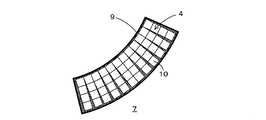
- FIG. 3 is an overall view showing the permanent magnet 4 according to the present invention.
- the permanent magnet 4 according to the present invention is formed by combining a plurality of standard magnets 10 having a predetermined standard shape as described above.
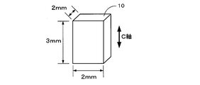
- the standard magnet 10 constituting the permanent magnet 4 is a rare earth permanent magnet, and in particular, an Nd—Fe—B anisotropic magnet is used.
- the content of each component is Nd: 27 to 40 wt%, B: 0.8 to 2 wt%, and Fe (electrolytic iron): 60 to 70 wt%.
- the standard magnet 10 is a permanent magnet having a standard shape of about 1 mm to 5 mm, for example. And by sintering the molded object (green sheet) shape
- the standard magnet 10 there are a plurality of types of standard magnets 10 having different magnetic performances. Further, there are standard magnets 10 of a plurality of sizes for each magnetic performance. That is, if there are three types of standard magnets 10 with different magnetic performances and each has three types of sizes, there will be nine types of standard magnets 10 in total.
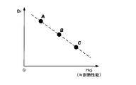
- the magnetic performance of the standard magnet 10 is defined by a combination of coercive force (Hcj) and residual magnetic flux density (Br), for example.
- Hcj coercive force
- Br residual magnetic flux density
- rare earth permanent magnets such as Nd—Fe—B are added with Dy, Tb, etc. in order to increase the coercive force.
- Dy, Tb, or the like when Dy, Tb, or the like is added, the coercive force (Hcj) increases as shown in FIG. 4, but the residual magnetic flux density (Br) decreases. Therefore, it is necessary to properly use permanent magnets having appropriate magnetic performance depending on applications (for example, for hybrid cars, air conditioners, hard disks, etc.) using permanent magnets.
- the plurality of types of standard magnets 10 having different magnetic performances have different colors for each type so that the user can distinguish them.
- the surface of the standard magnet 10 may be painted after sintering, or the standard magnet 10 is formed and sintered in a state in which a material that becomes a pigment is included in advance. It is good also as manufacturing.
- Dy, Tb, etc. As a method of adding Dy, Tb, etc., if Dy, Tb, etc. are unevenly arranged at the grain boundaries of the magnet, it is possible to improve the magnet performance while making the addition amount small. And as a method of unevenly arranging Dy, Tb, etc. at the grain boundaries of the magnet, for example, a grain boundary diffusion method in which Dy, Tb, etc. are attached to the surface of the sintered magnet and diffused, or the main phase and grain boundaries There are two alloy methods in which powders corresponding to phases are separately manufactured and mixed (dry blended), and a method in which an organometallic compound containing Dy, Tb, or the like is attached to the surface of magnet particles and then sintered. . Here, especially when adding Dy, Tb, etc.
- the size of the standard magnet 10 can be set as appropriate. For example, as shown in FIG. 5, there are three types of cubes: a cube with a side of 4 mm, a cube with a side of 2 mm, and a cube with a side of 1 mm.
- the size of the standard magnet 10 may be two types or four or more types, and the shape can be arbitrarily set in addition to the size for each type. For example, you may prescribe
- the permanent magnet along the shape of the slot 9 can be obtained by combining the standard magnets 10 regardless of the shape of the slot 9. 4 can be formed. Further, as will be described later, it is possible to combine a plurality of types of standard magnets 10 having different sizes in the same permanent magnet 4.
- the standard magnet 10 is an anisotropic magnet, and the C-axis (easy magnetization axis) of the magnet crystal 13 is oriented in one direction by performing magnetic field orientation as described later. And when combining the standard magnet 10 and forming the permanent magnet 4, it combines so that the C-axis direction of each standard magnet 10 may become the same direction. After a plurality of standard magnets 10 are combined and accommodated in the slot 9, magnetization is performed by applying a magnetic field in parallel to the C-axis direction of each standard magnet 10. Thereby, the magnetic characteristics of the permanent magnet 4 can be greatly improved.
- the standard magnets 10 when combining a plurality of standard magnets 10 so that the C-axis directions are the same direction, the standard magnets 10 should be shaped so that the C-axis direction can be easily discriminated in order to facilitate the combination. desirable. Specifically, the standard magnet 10 is shaped differently in the C-axis direction and other axial directions.
- the shape of the standard magnet 10 is a columnar shape (rectangular column, cylinder, etc.) with the C-axis direction as the height direction, and the length in the C-axis direction is the length in the other axial direction. If the shape is made longer (especially in the case of a rectangular parallelepiped, the length of the side in the C-axis direction is longer than the length of the other side), the C-axis direction of the standard magnet 10 can be easily determined. .
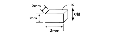
- the shape of the standard magnet 10 is a columnar shape (rectangular column, cylinder, etc.) with the C-axis direction as the height direction, and the length in the C-axis direction is the length in the other axial direction. If the shape is made shorter (especially in the case of a rectangular parallelepiped, the length of the side in the C-axis direction is shorter than the length of the other side), the C-axis direction of the standard magnet 10 can be easily determined. Become. 7 and 8, the standard magnet 10 is a rectangular parallelepiped, but it may be a cylinder, a hexagonal column, or the like. Further, as long as the C-axis direction can be discriminated, a spheroid (oblate, oblate) or the like may be used in addition to the columnar shape.
- a spheroid oblate, oblate
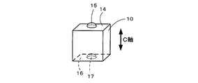
- the C-axis direction is not discriminated by the shape of the standard magnet 10 itself as shown in FIGS. 7 and 8, but the member serving as a mark is added to the standard magnet 10 as shown in FIG. It may be discriminated.
- the engaging portion 15 is formed on one surface 14 orthogonal to the C-axis direction of the standard magnet 10 and the engaged portion 15 is engaged with the engaging portion 15 on the other surface 16. 17 is formed.
- the engaging portion 15 is a convex member and the engaged portion 17 is a concave member.
- the shapes may be reversed or may be shapes that engage with each other. Other shapes may be used.
- a plurality of engaging portions 15 and engaged portions 17 may be formed on the surfaces 14 and 16. Furthermore, it is good also as a structure which forms the engaging part 15 or the to-be-engaged part 17 also about surfaces other than the surfaces 14 and 16 orthogonal to a C-axis direction. However, in that case, the shape and the number of installed portions 15 and engaged portions 17 formed on the surfaces 14 and 16 orthogonal to the C-axis direction so that the C-axis direction can be discriminated from other surfaces are different. It is desirable to make it.
- an insulating layer may be arranged at the boundary between adjacent standard magnets 10 when combined.
- the shaft 8 Need to rotate at high speed. And if it rotates at high speed, an eddy current will generate
- the permanent magnet 4 since the permanent magnet 4 is not integrally molded as described above, but is divided into a plurality of standard magnets 10, the size of eddy current generated inside the permanent magnet 4 is reduced. Even when the permanent magnet motor 1 is rotated at a high speed, it is possible to suppress an increase in the temperature of the permanent magnet. Further, if an insulating layer is arranged at the boundary between adjacent standard magnets 10, the eddy current path can be more reliably blocked by the insulating layer, and the scale of the eddy current generated inside the permanent magnet 4 can be reduced. .
- a method of arranging an insulating layer at the boundary between adjacent standard magnets 10 when combined for example, there is a method of coating the surface of each standard magnet 10 with an insulating layer in advance before combining the standard magnets 10.
- the insulating layer to be coated include ceramic and resin.
- the permanent magnet 4 is formed by combining the standard magnets 10
- a material for example, resin
- the standard magnets 10 are basically combined so that the C-axis directions of the standard magnets 10 are the same direction. good.
- the standard magnet 10 may be combined with a combination that allows the permanent magnet 4 to be anisotropically magnetized so as to satisfy the Halbach array.
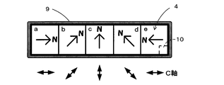
- FIG. 12 is a diagram showing the permanent magnet 4 anisotropically magnetized so as to satisfy the Halbach array.
- the permanent magnet 4 is constituted by the adjacent areas a to e, and the standard magnet 10 is combined so that the C-axis direction is continuously changed for each area a to e. And is accommodated in the slot 9. Thereafter, the permanent magnet 4 satisfying the Halbach array is obtained by magnetizing the permanent magnet 4 along the C-axis direction of each area a to e so that the direction of the N pole (or S pole) is continuously changed. It can be configured.
- a resin, a long-chain hydrocarbon, a fatty acid methyl ester, a mixture thereof, or the like is used as the binder mixed with the magnet powder.
- a resin it is preferable to use a polymer that does not contain an oxygen atom in the structure and has a depolymerization property.
- a thermoplastic resin is used to perform magnetic field orientation in a state where the formed green sheet is heated and softened.
- the polymer which consists of 1 type, or 2 or more types of polymers or copolymers chosen from the monomer shown by the following general formula (1) corresponds.
- R1 and R2 represent a hydrogen atom, a lower alkyl group, a phenyl group or a vinyl group.
- polystyrene resin examples include polyisobutylene (PIB), which is a polymer of isobutylene, polyisoprene (isoprene rubber, IR), which is a polymer of isoprene, and polybutadiene (butadiene) that is a polymer of 1,3-butadiene.
- PIB polyisobutylene
- IR polyisoprene rubber
- IR isoprene rubber
- IR isoprene rubber
- butadiene butadiene
- Rubber, BR polystyrene as a polymer of styrene, styrene-isoprene block copolymer (SIS) as a copolymer of styrene and isoprene, butyl rubber (IIR) as a copolymer of isobutylene and isoprene, styrene and butadiene
- SIS styrene-isoprene block copolymer
- IIR butyl rubber
- SBS styrene-butadiene block copolymer which is a copolymer of 2-methyl-1-pentene, a polymer of 2-methyl-1-pentene, and a polymer of 2-methyl-1-butene.
- a 2-methyl-1-butene polymer resin a polymer of ⁇ -methylstyrene That there is ⁇ - methyl styrene polymer resin.
- the resin used for the binder may include a small amount of a polymer or copolymer of a monomer containing an oxygen atom (for example, polybutyl methacrylate, polymethyl methacrylate, etc.).
- a monomer that does not correspond to the general formula (1) may be partially copolymerized. Even in that case, it is possible to achieve the object of the present invention.
- thermoplastic resin that softens at 250 ° C. or lower, more specifically a thermoplastic resin having a glass transition point or a melting point of 250 ° C. or lower in order to appropriately perform magnetic field orientation. .
- a long chain hydrocarbon when used for the binder, it is preferable to use a long chain saturated hydrocarbon (long chain alkane) that is solid at room temperature and liquid at room temperature or higher. Specifically, it is preferable to use a long-chain saturated hydrocarbon having 18 or more carbon atoms.
- molding so that it may mention later is magnetic field orientation
- magnetic field orientation is performed in the state which heated the green sheet above melting
- fatty acid methyl ester when used as the binder, it is preferable to use methyl stearate or methyl docosanoate which is solid at room temperature and liquid at room temperature or higher.
- methyl stearate or methyl docosanoate which is solid at room temperature and liquid at room temperature or higher.
- magnetic field orientation magnetic field orientation is performed in the state which heated the green sheet above melting
- the amount of carbon and oxygen contained in the magnet can be reduced.
- the amount of carbon remaining in the magnet after sintering is 2000 ppm or less, more preferably 1000 ppm or less.
- the amount of oxygen remaining in the magnet after sintering is set to 5000 ppm or less, more preferably 2000 ppm or less.
- the amount of the binder added is an amount that appropriately fills the gaps between the magnet particles in order to improve the thickness accuracy of the sheet when the slurry or the heated and melted compound is formed into a sheet.
- the ratio of the binder to the total amount of magnet powder and binder is 1 wt% to 40 wt%, more preferably 2 wt% to 30 wt%, and even more preferably 3 wt% to 20 wt%.
- FIG. 13 is an overall view showing the permanent magnet 4 according to the present invention and the slot 9 in which the permanent magnet 4 is accommodated.
- the permanent magnet 4 according to the present invention is formed by combining a plurality of standard magnets 10 having a predetermined standard shape as described above.
- the slot 9 is designed to have a shape corresponding to the shape of the permanent magnet 4 in which a plurality of standard magnets 10 are combined.
- the slot 9 is The shape is made to correspond to the rectangular parallelepiped shape.
- a rectangular parallelepiped shape for example, 22 mm ⁇ 8.5 mm ⁇ 51 mm
- a predetermined grace distance for example, 0.5 to 3 mm
- the slot 9 is not necessarily a rectangular parallelepiped shape, and may be a cylindrical shape or the like.
- the shape of the slot 9 may be a shape having a fan-shaped cross section with respect to the accommodation direction of the standard magnet. And when accommodating the permanent magnet 4 with respect to the slot 9 which has a fan shape as shown in FIG. 15, when combining the standard magnet 10, the positional relationship of adjacent standard magnets 10 is according to a fan shape. Set. Accordingly, the permanent magnet 4 can be appropriately accommodated even in the slot 9 that draws a curved shape such as a fan shape. On the other hand, when an integrally molded permanent magnet is to be accommodated in a slot 9 having a fan shape as shown in FIG. 15, the permanent magnet must be processed into a complicated shape such as a fan shape. However, there is a problem that the manufacturing process becomes very complicated.
- the shape of the outer edge portion forming the slot 9 may be a shape corresponding to the shape of the standard magnet 10.
- the shape of the outer edge forming the slot 9 corresponds to the shape of the standard magnet 10 ( Step shape).
- the magnetic flux density does not change uniformly with respect to the standard magnet 10 accommodated in the slot 9, but a large magnetic flux density change occurs at a specific location.
- the slot 9 is arranged so as to have a substantially square shape along the axial direction of the rotor core 7 as shown in FIG. 1, the vicinity of the center of the paired permanent magnets 4 as shown in FIG. A particularly large change in magnetic flux density occurs at the corners. That is, there is a high possibility that a strong eddy current is generated at the same location, while there is a low possibility that a strong eddy current is generated at other locations.
- the standard magnets 10 having a particularly high coercive force are arranged only at locations where the change in magnetic flux density is large in the permanent magnet motor 1. If this is done, the amount of Dy or Tb used can be reduced in a state where the permanent magnet 4 retains its function as a magnet (that is, a state in which a coercive force equal to or higher than the reverse magnetic field can be maintained even if the temperature rises due to eddy current). This makes it possible to reduce manufacturing costs. For example, as shown in FIG. 18, the standard magnet 10 having a higher coercive force than other locations can be combined and housed at locations where the change in magnetic flux density is large.
- the standard magnets 10 having a high coercive force can be accommodated in combination so as to be arranged step by step as approaching a location where the change in magnetic flux density is large.
- the standard magnet 10 located outside the standard magnet 10 located inside is a standard magnet 10 having a higher coercive force.
- two types of standard magnets 10 having different coercive forces are combined in the inner and outer sections, but may be divided into three or more stages. As long as the standard magnet 10 having a high coercive force is disposed at a location where the change in magnetic flux density is large in the permanent magnet motor 1, combinations other than those shown in FIGS. 18 to 20 may be used.
- the standard magnets 10 constituting the permanent magnet 4 are not all combined with the standard magnets 10 of the same size, but the standard magnets 10 having a particularly small size are arranged only at locations where the change in the magnetic flux density is large in the permanent magnet motor 1. Then, the scale of the eddy current generated in the permanent magnet 4 can be further reduced without particularly reducing the productivity of the permanent magnet 4.
- the standard magnets 10 having a smaller size than other portions can be combined and housed at a location where the change in magnetic flux density is large.
- the standard magnets 10 whose size is gradually reduced can be combined and housed as they approach a location where the change in magnetic flux density is large. Furthermore, as shown in FIG.
- the standard magnet 10 positioned outside the standard magnet 10 positioned inside may be combined so that the standard magnet 10 having a smaller size is obtained.
- the standard magnets 10 of two types of sizes are combined in the inner and outer sections, but may be divided into three or more stages. As long as the standard magnet 10 having a small size is arranged at a location where the change in the magnetic flux density is large in the permanent magnet motor 1, combinations other than those shown in FIGS. 21 to 23 may be used.
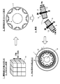
- FIG. 24 is an explanatory view showing a manufacturing process until the standard magnet 10 is manufactured.
- an ingot made of a predetermined fraction of Nd—Fe—B (eg, Nd: 32.7 wt%, Fe (electrolytic iron): 65.96 wt%, B: 1.34 wt%) is manufactured. Thereafter, the ingot is roughly pulverized to a size of about 200 ⁇ m by a stamp mill or a crusher. Alternatively, the ingot is melted, flakes are produced by strip casting, and coarsely pulverized by hydrogen crushing. Thereby, coarsely pulverized magnet powder 30 is obtained.
- Nd—Fe—B eg, Nd: 32.7 wt%, Fe (electrolytic iron): 65.96 wt%, B: 1.34 wt%
- the coarsely pulverized magnet powder 30 is finely pulverized by a wet method using a bead mill 31 or a dry method using a jet mill.
- the coarsely pulverized magnet powder 30 is finely pulverized in an organic solvent to a predetermined particle size (for example, 0.1 ⁇ m to 5.0 ⁇ m), and the magnet powder is dispersed in the organic solvent. Disperse. Thereafter, the magnet powder contained in the organic solvent after the wet pulverization is dried by vacuum drying or the like, and the dried magnet powder is taken out.
- the solvent used for the pulverization is an organic solvent, but the type of the solvent is not particularly limited, alcohols such as isopropyl alcohol, ethanol and methanol, esters such as ethyl acetate, lower hydrocarbons such as pentane and hexane, Aromatics such as benzene, toluene and xylene, ketones, mixtures thereof and the like can be used.
- a hydrocarbon solvent that does not contain an oxygen atom in the solvent is used.
- coarsely pulverized magnet powder is (a) in an atmosphere composed of an inert gas such as nitrogen gas, Ar gas, and He gas having substantially 0% oxygen content.
- the oxygen concentration of substantially 0% is not limited to the case where the oxygen concentration is completely 0%, but may contain oxygen in such an amount that a very small amount of oxide film is formed on the surface of the fine powder. Means good.
- the magnet powder finely pulverized by the bead mill 31 or the like is molded into a desired shape.
- the molding of the magnet powder includes, for example, compaction molding that forms a desired shape using a mold and green sheet molding in which the magnet powder is once formed into a sheet shape and then punched into the desired shape.
- compaction molding that forms a desired shape using a mold and green sheet molding in which the magnet powder is once formed into a sheet shape and then punched into the desired shape.
- green sheet molding for example, hot melt coating for molding a compound in which magnet powder and a binder are mixed into a sheet, or slurry containing magnet powder, a binder, and an organic solvent is coated on a substrate. There is molding by slurry coating or the like to form a sheet.
- a powdery mixture (compound) 32 composed of magnet powder and binder is prepared by mixing a binder with magnet powder.
- the binder resin, long chain hydrocarbon, fatty acid methyl ester, a mixture thereof, or the like is used as described above.
- a resin a thermoplastic resin made of a depolymerizable polymer that does not contain an oxygen atom in the structure is used.
- a long-chain hydrocarbon the resin is solid at room temperature or above room temperature. It is preferable to use a long-chain saturated hydrocarbon (long-chain alkane) that is liquid.
- the amount of the binder added is such that the ratio of the binder to the total amount of the magnet powder and the binder in the compound 12 after the addition is 1 wt% to 40 wt%, more preferably 2 wt% to 30 wt%, still more preferably 3 wt%. % To 20 wt%.
- the binder is added in an atmosphere made of an inert gas such as nitrogen gas, Ar gas, or He gas.
- the mixing of the magnet powder and the binder is performed, for example, by putting the magnet powder and the binder in an organic solvent and stirring with a stirrer.
- the compound 12 is extracted by heating the organic solvent containing magnet powder and a binder after stirring, and vaporizing an organic solvent.
- the mixing of the magnet powder and the binder is preferably performed in an atmosphere made of an inert gas such as nitrogen gas, Ar gas, or He gas.
- an inert gas such as nitrogen gas, Ar gas, or He gas.
- the binder is added to the organic solvent and kneaded without taking out the magnet powder from the organic solvent used for pulverization, and then the organic solvent is volatilized to be described later. It is good also as a structure which obtains the compound 12.
- a green sheet is created by forming the compound 32 into a sheet shape.
- the compound 32 in the hot melt coating, the compound 32 is heated to melt the compound 32 to be in a fluid state, and then applied onto the support substrate 33 such as a separator. Then, the long sheet-like green sheet 34 is formed on the support base material 33 by heat radiation and solidifying.
- the temperature at which the compound 32 is heated and melted is 50 to 300 ° C., although it varies depending on the kind and amount of the binder used. However, the temperature needs to be higher than the melting point of the binder to be used.
- magnet powder and a binder are disperse
- the coating method of the melted compound 32 it is preferable to use a method having excellent layer thickness controllability such as a slot die method and a calendar roll method.
- a method having excellent layer thickness controllability such as a slot die method and a calendar roll method.
- the slot die method coating is performed by extruding a heated compound 32 in a fluid state by a gear pump and inserting the compound 32 into a die.
- the calendar roll method a certain amount of the compound 32 is charged into the gap between the two heated rolls, and the compound 32 melted by the heat of the roll is applied onto the support substrate 33 while rotating the roll.
- a silicone-treated polyester film is used as the support base material 33.
- the film is formed on the support substrate 33 by forming the compound 32 melted by extrusion molding into a sheet shape and extruding the support substrate 33 instead of coating on the support substrate 33. It is good also as composition to do.
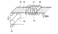
- FIG. 25 is a schematic view showing a process of forming the green sheet 34 by the slot die method.
- the die 35 used in the slot die system is formed by overlapping blocks 36 and 37, and a slit 38 and a cavity (liquid reservoir) 39 are formed by a gap between the blocks 36 and 37.
- the cavity 39 communicates with a supply port 40 provided in the block 37.
- the supply port 40 is connected to a coating liquid supply system constituted by a gear pump (not shown) or the like, and the measured fluid-like compound 32 is quantified in the cavity 39 via the supply port 40. Supplied by a pump or the like.
- the fluid compound 32 supplied to the cavity 39 is fed to the slit 38 and discharged from the discharge port 41 of the slit 38 with a predetermined application width with a uniform amount in the width direction at a constant amount per unit time.
- the support base material 33 is continuously conveyed at a preset speed with the rotation of the coating roll 42.
- the ejected fluid compound 32 is applied to the support base material 33 at a predetermined thickness, and then heat radiation and solidification are performed to form a long sheet-like green sheet 34 on the support base material 33. Is done.
- the sheet thickness of the green sheet 34 after coating is measured, and the gap D between the die 35 and the support base material 33 is feedback-controlled based on the measured value. desirable. Further, the fluctuation of the amount of the fluid compound 32 supplied to the die 35 is reduced as much as possible (for example, suppressed to fluctuation of ⁇ 0.1% or less), and the fluctuation of the coating speed is further reduced as much as possible (for example, ⁇ 0. It is desirable to suppress the fluctuation to 1% or less. Thereby, the thickness accuracy of the green sheet 34 can be further improved.
- the thickness accuracy of the formed green sheet 34 is within ⁇ 10%, more preferably within ⁇ 3%, and even more preferably within ⁇ 1% with respect to the design value (for example, 2 mm).
- the transfer film thickness of the compound 32 to the support base material 33 can be controlled by similarly controlling the calendar conditions based on the actually measured values.
- the set thickness of the green sheet 34 is desirably set in the range of 0.05 mm to 20 mm. When the thickness is less than 0.05 mm, the productivity must be reduced because multiple layers must be stacked.
- a green sheet that has been divided into the standard shape of the standard magnet 10 in advance may be formed.
- a molding frame 44 in which a plurality of standard-shaped molds 43 as shown in FIG. 26 are formed in parallel is placed on the support base material 33, and a slurry in which magnet powder and a binder are mixed or a melted compound is used.
- a green sheet is formed by coating from above the forming frame 44.
- the green magnet can be formed into the standard magnet 10 without performing punching into a standard shape as described later by removing the green sheet from the molding frame 44 after the magnetic field orientation.
- the magnetic orientation of the green sheet 34 formed on the support base material 33 by the hot melt coating described above is performed.
- the green sheet 34 is first softened by heating the green sheet 34 that is continuously conveyed together with the support base material 33.
- the temperature and time for heating the green sheet 34 vary depending on the type and amount of the binder used, but are, for example, 100 to 250 ° C. and 0.1 to 60 minutes. However, in order to soften the green sheet 34, the glass transition point of the binder to be used or a temperature higher than the melting point is required.
- a heating method for heating the green sheet 34 for example, there are a heating method using a hot plate and a heating method using a heat medium (silicone oil) as a heat source.
- magnetic field orientation is performed by applying a magnetic field to the in-plane direction and the length direction of the green sheet 34 softened by heating.
- the intensity of the applied magnetic field is 5000 [Oe] to 150,000 [Oe], preferably 10,000 [Oe] to 120,000 [Oe].
- the C-axis (easy magnetization axis) of the magnet crystal included in the green sheet 34 is oriented in one direction.
- the magnetic field may be applied in the in-plane direction and the width direction of the green sheet 34. Moreover, it is good also as a structure which orientates a magnetic field simultaneously with respect to the some green sheet 34.
- a configuration in which a magnetic field is applied at the same time as the heating process may be performed, or a magnetic field may be applied after the heating process and before the green sheet solidifies. It is good also as performing the process to perform. Moreover, it is good also as a structure which magnetic field orientates before the green sheet 34 coated by hot-melt coating solidifies. In that case, the heating step is not necessary.
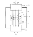
- FIG. 27 is a schematic diagram showing a heating process and a magnetic field orientation process of the green sheet 34.
- FIG. 27 an example in which the magnetic field orientation process is performed simultaneously with the heating process will be described.
- heating and magnetic field orientation on the green sheet 34 coated by the above-described slot die method are performed on the long sheet-like green sheet 34 that is continuously conveyed by a roll. That is, an apparatus for performing heating and magnetic field orientation is disposed on the downstream side of the coating apparatus (die or the like), and is performed by a process continuous with the above-described coating process.
- the solenoid 45 is disposed on the downstream side of the die 35 and the coating roll 42 so that the support base material 33 and the green sheet 34 to be conveyed pass through the solenoid 45. Further, the hot plates 46 are arranged in a pair above and below the green sheet 34 in the solenoid 45. Then, the green sheet 34 is heated by a pair of upper and lower hot plates 46 and a current is passed through the solenoid 45 so that the in-plane direction of the long green sheet 34 (that is, the sheet surface of the green sheet 34). A magnetic field in the longitudinal direction).
- the continuously conveyed green sheet 34 is softened by heating, and a magnetic field is applied to the in-plane direction and the length direction of the softened green sheet 34 (in the direction of arrow 47 in FIG. 27).
- a magnetic field is applied to the in-plane direction and the length direction of the softened green sheet 34 (in the direction of arrow 47 in FIG. 27).
- the surface of the green sheet 34 can be prevented from standing upright by setting the direction in which the magnetic field is applied to the in-plane direction.
- a pair of magnetic field coils are arranged on the left and right sides of the green sheet 34 conveyed instead of the solenoid 45. Then, by supplying a current to each magnetic field coil, it is possible to generate a magnetic field in the in-plane direction and the width direction of the long sheet-like green sheet 34.
- the magnetic field orientation can be set to the in-plane vertical direction of the green sheet 34.
- the magnetic field application device using a pole piece or the like is used.
- a magnetic field application device 50 using a pole piece or the like includes two ring-shaped coil portions 51 and 52 arranged in parallel so that the central axes are the same, and the coil portion 51. , 52 and two substantially cylindrical pole pieces 53 and 54 respectively disposed in the ring holes, and are spaced apart from the conveyed green sheet 34 by a predetermined distance.
- the magnetic field orientation direction is the in-plane vertical direction of the green sheet 34
- a film 55 is laminated on the opposite side of the green sheet 34 on which the support base material 33 is laminated as shown in FIG. It is preferable to do. Thereby, it is possible to prevent the surface of the green sheet 34 from standing upside down.
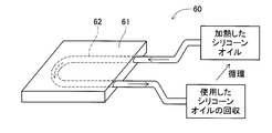
- FIG. 29 is a diagram showing an example of a heating device 60 using a heat medium.
- the heating device 60 forms a substantially U-shaped cavity 62 inside a flat plate member 61 serving as a heating element, and heat heated to a predetermined temperature (for example, 100 to 300 ° C.) in the cavity 62. It is set as the structure which circulates the silicone oil which is a medium.
- the heating device 60 is arranged in a pair above and below the green sheet 34 in the solenoid 45.
- the continuously conveyed green sheet 34 is heated and softened through the flat plate member 61 generated by the heat medium.
- the flat plate member 61 may be brought into contact with the green sheet 34 or may be arranged at a predetermined interval.
- a magnetic field is applied to the in-plane direction and the length direction (in the direction of arrow 47 in FIG. 27) of the green sheet 34 by the solenoid 45 arranged around the softened green sheet 34, An appropriate uniform magnetic field can be oriented.
- the heating device 60 using the heat medium as shown in FIG. 29 does not have a heating wire inside unlike a general hot plate 46, so even if it is placed in a magnetic field, There is no possibility that the heating wire vibrates or is cut, and the green sheet 34 can be appropriately heated.
- the heating device 60 using a heat medium as the heat source, Such a problem can be solved.
- the green sheet 34 is formed from a liquid material having high fluidity such as slurry by a general slot die method or doctor blade method without using hot melt molding, a magnetic field gradient is generated.
- the magnetic powder contained in the green sheet 34 is attracted toward the stronger magnetic field, and the liquid of the slurry forming the green sheet 34, that is, the thickness of the green sheet 34 is uneven. May occur.
- the compound 32 is molded into the green sheet 34 by hot melt molding as in the present invention, the viscosity near room temperature reaches several tens of thousands Pa ⁇ s, and the magnetic powder tends to shift when passing through the magnetic field gradient. It does not occur.
- the viscosity of the binder is lowered by being transported and heated in a uniform magnetic field, and uniform C-axis orientation is possible only by the rotational torque in the uniform magnetic field.
- the thickness exceeds 1 mm.
- foaming due to vaporization of the organic solvent contained in the slurry or the like at the time of drying becomes a problem.
- the drying time is prolonged to suppress foaming, the magnet powder is settled, and accordingly, the density distribution of the magnet powder is biased with respect to the direction of gravity, which causes warping after firing. Therefore, in the molding from the slurry, the upper limit value of the thickness is substantially regulated, so it is necessary to mold the green sheet with a thickness of 1 mm or less and then laminate it.
- the green sheet 34 subjected to magnetic field orientation is punched into a desired standard shape (for example, a rectangular parallelepiped shape shown in FIGS. 7 to 9), and a molded body 65 is formed.
- a desired standard shape for example, a rectangular parallelepiped shape shown in FIGS. 7 to 9
- a non-oxidizing atmosphere (particularly a hydrogen atmosphere or hydrogen in the present invention) in which the molded body 65 is pressurized to atmospheric pressure, or a pressure higher or lower than atmospheric pressure (for example, 1.0 Pa or 1.0 MPa).
- an inert gas mixed gas atmosphere at a binder decomposition temperature for several hours (for example, 5 hours) to perform a calcination treatment.
- the supply amount of hydrogen during calcination is set to 5 L / min.
- decarbonization for reducing the amount of carbon in the molded body 65 is performed.
- the calcining treatment is performed under the condition that the carbon content in the molded body 65 is 2000 ppm or less, more preferably 1000 ppm or less. Accordingly, the entire permanent magnet can be densely sintered by the subsequent sintering process, and the residual magnetic flux density and coercive force are not reduced.
- the binder decomposition temperature is determined based on the analysis results of the binder decomposition product and decomposition residue. Specifically, a temperature range is selected in which decomposition products of the binder are collected, decomposition products other than the monomers are not generated, and products due to side reactions of the remaining binder components are not detected even in the analysis of the residues. Although it varies depending on the type of the binder, it is set to 200 ° C. to 900 ° C., more preferably 400 ° C. to 600 ° C. (eg 600 ° C.).
- the calcining treatment is performed at the thermal decomposition temperature and binder decomposition temperature of the organic compound constituting the organic solvent. Thereby, the remaining organic solvent can be removed.
- the thermal decomposition temperature of the organic compound is determined depending on the type of the organic solvent to be used, but basically the thermal decomposition of the organic compound can be performed at the binder decomposition temperature.
- NdH 3 (high activity) in the molded body 65 produced by the calcination treatment is changed stepwise from NdH 3 (high activity) ⁇ NdH 2 (low activity).
- the activity of the molded body 65 activated by the calcination treatment is reduced.
- the sintering process which sinters the molded object 65 calcined by the calcining process is performed.
- a sintering method of the molded body 65 it is possible to use pressure sintering which sinters in a state where the molded body 65 is pressed in addition to general vacuum sintering.
- the temperature is raised to a firing temperature of about 800 ° C. to 1080 ° C. at a predetermined temperature increase rate and held for about 0.1 to 2 hours.
- vacuum firing is performed, but the degree of vacuum is preferably 5 Pa or less, and preferably 10 ⁇ 2 Pa or less.
- it is cooled and heat-treated again at 300 ° C. to 1000 ° C. for 2 hours.
- the standard magnet 10 is manufactured.
- pressure sintering examples include hot press sintering, hot isostatic pressing (HIP) sintering, ultrahigh pressure synthetic sintering, gas pressure sintering, and discharge plasma (SPS) sintering.
- HIP hot isostatic pressing
- SPS discharge plasma
- the SPS is uniaxial pressure sintering that pressurizes in a uniaxial direction and is sintered by current sintering. Sintering is preferably used.
- the pressure value is set to, for example, 0.01 MPa to 100 MPa, the pressure is increased to 940 ° C.
- the standard magnet 10 is manufactured.
- FIG. 30 is an explanatory view showing a pressure sintering process of the molded body 65 by SPS sintering.
- a compact 65 is placed on a graphite sintering die 71.
- the calcination treatment described above may also be performed in a state where the molded body 65 is installed in the sintering mold 71.
- the compact 65 installed in the sintering die 71 is held in the vacuum champ 72, and an upper punch 73 and a lower punch 74 made of graphite are also set.
- the molded body 65 installed in the sintering die 71 is sintered while being pressurized.
- FIG. 31 is an explanatory view showing a manufacturing process until the permanent magnet motor 1 is manufactured using the standard magnet 10.
- the permanent magnet 4 is formed by combining a plurality of standard magnets 10 manufactured by the manufacturing process shown in FIG. Note that the step of combining the standard magnet 10 and the step of accommodating the standard magnet 10 may be performed simultaneously, or the step of combining the standard magnet 10 first and then the step of accommodating the standard magnet 10 may be performed. Further, the standard magnet 10 before being combined may be lightly magnetized (first stage magnetization). As a result, the standard magnets 10 can be easily combined. Then, after the lightly magnetized standard magnet 10 is accommodated in the slot 9, final magnetization (second stage magnetization) may be performed.
- the process of combining the standard magnets 10 is performed first, the plurality of standard magnets 10 combined are fixed in a state corresponding to the slot 9 by combining a plurality of standard magnets 10.
- a plurality of standard magnets 10 are accommodated in the slots 9.
- the standard magnet 10 is sequentially accommodated in the slot 9 to be combined into a shape corresponding to the slot 9. In that case, it is not always necessary to fix the combined standard magnets 10 together.
- the standard magnet 10 when combining the standard magnet 10, it combines so that the C-axis direction of each standard magnet 10 may become the same direction. Further, as will be described later, in the present invention, magnetization is performed by applying a magnetic field parallel to the C-axis direction of each standard magnet 10. Therefore, it is necessary to combine the standard magnets 10 in consideration of the magnetization direction and accommodate them in the slots 9. Specifically, the standard magnets 10 are combined and accommodated in the slot 9 so that the radial direction of the rotor core 7 and the C-axis direction of the standard magnet 10 coincide. However, as described above, when the permanent magnets 4 are magnetized in the Halbach array, the C-axis directions of the standard magnets 10 are continuously changed and combined and accommodated in the slot 9 (see FIG. 12).
- the permanent magnet 4 accommodated in the slot 9 is fixed to the slot 9 by filling the slot 9 with the filler 11.
- magnetization is performed by applying a magnetic field to the permanent magnet 4 accommodated in the slot 9.
- the pair of permanent magnets 4 are magnetized so that the polarities on the rotor outer peripheral side are the same, and the adjacent pairs have different polarities. Magnetize like so. That is, as shown in FIG. 31, in the rotor core 7 in which a total of 16 permanent magnets 4 are accommodated in 8 pairs, 8 magnetic poles are constituted by 8 pairs of permanent magnets 4. Then, N poles and S poles are alternately arranged along the circumferential direction of the rotor core 7.
- the standard magnets 10 are combined and accommodated in the slots 9 so that the radial direction of the rotor core 7 and the C-axis direction of the standard magnets 10 coincide with each other, so that they are parallel to the C-axis direction of each standard magnet 10.
- a magnetic field is applied.
- the permanent magnet 4 is magnetized in the Halbach arrangement as described above, the permanent magnet 4 is magnetized so that the direction of the N pole (or S pole) is continuously changed (see FIG. 12).
- a magnetizing coil, a magnetizing yoke, a condenser magnetizing power supply device, or the like is used for magnetizing the permanent magnet 4, for example, a magnetizing coil, a magnetizing yoke, a condenser magnetizing power supply device, or the like is used.
- the permanent magnet motor 1 is manufactured by assembling members other than the rotor core 7 such as the shaft 8 and the stator 2.
- the permanent magnet 4 accommodated in the slot 9 formed in the rotor core 7 of the permanent magnet motor 1 is formed into a predetermined standard shape.
- the standard magnet 10 is a permanent magnet having a plurality of standard magnets, and the slot 9 is designed to have a shape corresponding to a combination of a plurality of standard magnets 10. It becomes possible to form permanent magnets 4 corresponding to various types of permanent magnet motors 1 by combination. As a result, it is not necessary to manufacture the permanent magnet 4 having a different shape for each permanent magnet motor, so that the manufacturing efficiency can be dramatically increased.
- the permanent magnet 4 having a complicated shape by changing the combination of the standard magnets 10 as compared with the case of using an integrally molded permanent magnet.
- the type of standard magnets 10 to be combined is changed depending on applications (for example, for hybrid cars, for air conditioning, and for hard disks). By this, it becomes possible to form the permanent magnet 4 which has the magnetic performance according to a use.
- the permanent magnet 4 retains its function as a magnet (ie, the temperature due to the eddy current). Even in the case where the coercive force is higher than the reverse magnetic field), the amount of Dy and Tb used can be reduced, and the manufacturing cost can be reduced. Further, when the standard magnet 10 is combined, if the standard magnet 10 positioned on the outer side is combined with the standard magnet 10 having a higher coercive force than the standard magnet 10 positioned on the inner side, the permanent magnet 4 is used.
- the standard magnet 10 can reduce the amount of Dy and Tb used and the manufacturing cost while maintaining the function as a magnet (that is, a state in which a coercive force higher than the reverse magnetic field can be maintained even if the temperature rises due to eddy current). Become. Moreover, since the standard magnet 10 has a different color for each magnetic performance, even if there are a plurality of types of standard magnets 10 having different magnetic performance, the user can easily determine the magnetic performance of the standard magnet 10 from the appearance. It becomes. Further, since there are a plurality of types of standard magnets 10 having different sizes, the standard magnet 10 can be formed in any shape by changing the size of the standard magnet 10 to be combined with the shape of the slot 9.
- the combination of 10 makes it possible to form the permanent magnet 4 along the shape of the housing portion. If the standard magnet 10 having a smaller size is disposed in a location where the change in the magnetic flux density is larger in the permanent magnet motor 1, the permanent magnet 4 is generated without particularly reducing the productivity of the permanent magnet 4. The scale of eddy current can be further reduced. Further, when the standard magnet 10 is combined, if the standard magnet 10 positioned on the outer side is combined with the standard magnet 10 having a smaller size than the standard magnet 10 positioned on the inner side, the permanent magnet 4 is used. The size of the eddy current generated in the permanent magnet 4 can be further reduced without particularly reducing the productivity.
- the standard magnet 10 is an anisotropic magnet, and a plurality of standard magnets 10 are combined and accommodated in the slot 9 so that the C-axis direction (magnetization easy axis) of each standard magnet 10 is the same direction.
- the magnetic performance of the permanent magnet 4 is greatly improved when magnetization is performed, compared to the case where an isotropic magnet is used or an anisotropic magnet is used and the C-axis direction is not combined in the same direction. It becomes possible.
- a plurality of standard magnets 10 are combined and accommodated in the slot 9, and a magnetic field is applied parallel to the C-axis direction of each standard magnet 10, magnetization is performed. Therefore, the permanent magnet 4 accommodated in the slot 9 is divided into a plurality of parts.
- the magnetic performance of the permanent magnet 4 can be greatly improved as in the case of using an integrally formed anisotropic magnet.
- the standard magnet 10 since the standard magnet 10 has different shapes in the C-axis direction and other axial directions, the C-axis direction of the standard magnet 10 can be easily distinguished from the external shape. As a result, even when the standard magnets 10 are combined so that the C-axis directions are the same, the combination work can be easily performed.
- the standard magnet 10 has a shape in which the length in the C-axis direction is shorter or longer than the length in the other axial directions, the C-axis direction of the standard magnet 10 can be easily distinguished from the appearance shape.
- the standard magnet 10 has a columnar shape with the C-axis direction as a height, the standard magnet 10 can be easily combined. Further, since the length in the C-axis direction is shorter or longer than the length in the other axial directions, the C-axis direction of the standard magnet 10 can be easily determined from the external shape. Further, since the standard magnet 10 is a rectangular parallelepiped and has a shape in which the length of the side in the C-axis direction is shorter or longer than the length of the other side, the C-axis direction of the standard magnet 10 can be easily determined from the appearance shape. Is possible.
- the engaging portion 15 is formed on one surface orthogonal to the C-axis direction of the standard magnet 10 and the engaged portion 17 that engages with the engaging portion 15 is formed on the other surface, the engaging portion It becomes possible to easily determine the C-axis direction of the standard magnet 10 using the 15 and the engaged portion 17 as a mark. Further, by engaging the engaging portion 15 and the engaged portion 17, it is possible to easily combine the plurality of standard magnets 10.
- the insulating layer 20 is formed at the boundary between the adjacent standard magnets 10 when combined, the eddy current generated in the permanent magnet 4 is reduced even when the permanent magnet motor 1 is rotated at a high speed. be able to. Therefore, it is possible to prevent a temperature increase and a decrease in coercive force of the permanent magnet 4 and provide a high-power small motor. Further, since the insulating layer 20 is formed with respect to the boundary parallel to the direction of the magnetic field generated in the permanent magnet motor 1, the effect of preventing eddy currents can be achieved while minimizing the location where the insulating layer 20 is formed. Is possible.
- the shape of the outer edge portion forming the slot 9 is a shape corresponding to the shape of the standard magnet 10 constituting the permanent magnet 4, the shape of the slot 9 or the standard magnet 10 is a special shape.
- the standard magnet 10 can be appropriately accommodated in the slot 9 and fixed.
- the standard magnet 10 can be appropriately accommodated in the slot 9 and fixed.
- the slot 9 has a fan-shaped cross section with respect to the accommodation direction of the standard magnet 10 and the standard magnets 10 are combined, the positional relationship between the adjacent standard magnets 10 is set according to the sector shape.
- the permanent magnet 4 can be shaped to correspond to the slot 9 by the combination of the standard magnets 10. Further, in a state where a plurality of standard magnets 10 are combined to form a shape corresponding to the slot 9, the combined plurality of standard magnets 10 are fixed to each other, and then the plurality of standard magnets 10 fixed are accommodated in the slot 9. As a result, even if the permanent magnet 4 is divided into a plurality of standard magnets 10, the standard magnet 10 can be easily accommodated in the slot 9.
- the standard magnets 10 that are adjacent to each other when they are combined are fixed to each other via an insulating layer disposed at the boundary, the standard magnets 10 can be appropriately fixed without deteriorating the magnetic properties.
- the eddy current generated in the permanent magnet 4 can be reduced. Therefore, it is possible to prevent a temperature increase and a decrease in coercive force of the permanent magnet 4 and provide a high-power small motor.
- the plurality of standard magnets 10 are sequentially accommodated in the slot 9 and combined with the shape corresponding to the slot 9, even if the permanent magnet 4 is divided into the plurality of standard magnets 10, the standard magnet 10. Can be appropriately taken into the slot 9.
- the process of combining the standard magnets 10 and the process of housing in the slot 9 can be performed simultaneously, the manufacturing process can be simplified.
- the first stage of magnetization is performed in advance before combining the standard magnets 10, the standard magnets 10 can be easily combined.
- the slot 9 for accommodating the permanent magnet 4 is formed along the axial direction of the rotor core 7, a permanent magnet embedded type motor such as an IPM motor used in a hybrid vehicle, an electric vehicle or the like is manufactured. Efficiency can be dramatically increased.
- the plurality of standard magnets 10 accommodated in the slot 9 are fixed to the slot 9 by filling the slot 9 with the filler 11, the permanent magnet 4 is divided by the plurality of standard magnets 10.
- each standard magnet 10 can be appropriately fixed to the slot 9.
- the standard magnet is composed of a magnet obtained by mixing magnet powder and a binder and sintering the formed green sheet 34, deformation due to sintering becomes uniform, and deformation such as warping and dent after sintering can be obtained. It does not occur, and pressure unevenness during pressing is eliminated, so that it is not necessary to carry out correction processing after sintering, which has been conventionally performed, and the manufacturing process can be simplified.
- a standard magnet having a predetermined standard shape can be formed with high dimensional accuracy. Further, even when the standard magnet has a minute shape, it is possible to prevent an increase in the number of processing steps without reducing the material yield.
- the standard magnet 10 is an Nd-based rare earth magnet
- the permanent magnets 4 can be arranged in a Halbach array. In that case, the C-axis direction (easy magnetization axis) of each standard magnet 10 is continuously changed so that the plurality of standard magnets 10 combined and accommodated in the slot 9 are magnetized in the Halbach array. combine. Accordingly, the combined standard magnets 10 (that is, the permanent magnets 4) can be arranged in a Halbach array. As a result, a stronger magnetic field can be generated.
- the pulverization conditions, kneading conditions, calcination conditions, sintering conditions, and the like of the magnet powder when manufacturing the standard magnet 10 are not limited to the conditions described in the above embodiments.
- the magnet raw material is pulverized by dry pulverization using a jet mill, but may be pulverized by wet pulverization using a bead mill.
- the green sheet is formed by the slot die method, but other methods (for example, calendar roll method, comma coating method, extrusion molding, injection molding, mold molding, doctor blade method, etc.) can be used. It may be used to form a green sheet. Moreover, it is good also as producing a green sheet by producing
- a hydrogen atmosphere for example, a nitrogen atmosphere, a He atmosphere, or an Ar atmosphere.
- the standard magnet may be manufactured by calcining and sintering a molded body formed by molding other than green sheet molding (for example, compaction molding). Even in such a case, the decarburization effect by calcining can be achieved for C-containing materials (added organometallic compounds, organic compounds remaining by wet pulverization, etc.) remaining in the molded body other than the binder. I can expect. Further, when a molded body formed by molding other than green sheet molding (for example, compaction molding) is calcined and sintered, the magnet powder before molding is calcined and calcined. It is good also as manufacturing a standard magnet by shape
- the surface area of the magnet to be calcined is increased compared to the case of calcining the molded magnet particles. can do. That is, the amount of carbon in the calcined body can be reduced more reliably.
- the calcination treatment may be omitted. Even in such a case, an organic compound such as a binder or an organic solvent is thermally decomposed during sintering, and a certain decarburization effect can be expected.
- resin long chain hydrocarbon or fatty acid methyl ester is used as the binder, but other materials may be used.
- the standard magnets 10 of a plurality of sizes exist for each magnetic performance, but only one type of size may be used.
- the magnetic performance may be common, and there may be a plurality of types of sizes. Further, the magnetic performance may be defined other than the coercive force and the residual magnetic flux density.
- the heating process and the magnetic field orientation process of the green sheet 34 are performed simultaneously.
- the magnetic field orientation process may be performed after the heating process and before the green sheet 34 is solidified. good.
- the heating process may be omitted. .
- the coating process by the slot die method, the heating process, and the magnetic field orientation process are performed by a series of continuous processes, but may be configured not to be performed by the continuous processes.
- the coated green sheet 34 can be cut to a predetermined length, and the green sheet 34 in a stationary state can be configured to perform magnetic field orientation by heating and applying a magnetic field. is there.
- an IPM motor mounted on a hybrid car is described as an example.
- the present invention is a vibration motor mounted on a mobile phone, a voice coil motor that drives a hard disk drive head, and a hard disk drive.
- the present invention can also be applied to a permanent magnet motor such as a spindle motor for rotating the disk, other air conditioning motors, servo motors, and OA / FA motors.
- the rotating field type motor in which the permanent magnet 4 is installed in the rotor (rotor) 3 has been described as an example.
- the present invention can also be applied to an armature type motor, a generator that is also a rotating electric machine, and the field side of a linear motor.
- a permanent magnet motor using an Nd—Fe—B system magnet has been described as an example, but other magnets (for example, a cobalt magnet, an alnico magnet, a ferrite magnet, etc.) may be used.
- the Nd component is larger than the stoichiometric composition in the present invention, but it may be stoichiometric.
- the present invention can be applied not only to anisotropic magnets but also to isotropic magnets. In that case, the magnetic field orientation process for the green sheet 34 can be omitted.
Abstract
Provided are a permanent magnet motor, a method of manufacturing a permanent magnet motor, and a permanent magnet wherein the efficiency of manufacture is enormously increased by employing a combination of permanent magnets of standard shape. A permanent magnet (4) accommodated in a slot (9) formed in a rotor core (7) of a permanent magnet motor (1) is constituted by combining a plurality of standard permanent magnets (10), which are permanent magnets having a prescribed standard shape. Also, the shape of the slot (9) is designed in a shape corresponding to the shape of the combination of a plurality of standard permanent magnets (10).
Description
本発明は、永久磁石モータ、永久磁石モータの製造方法及び永久磁石モータに収容される永久磁石に関する。
The present invention relates to a permanent magnet motor, a method of manufacturing a permanent magnet motor, and a permanent magnet accommodated in the permanent magnet motor.
近年、ハイブリッドカーやハードディスクドライブ等に使用される永久磁石モータでは、小型軽量化、高出力化、高効率化が要求されている。このような永久磁石モータとしては、永久磁石をロータ(回転子)に設置する回転界磁型のモータや、永久磁石をステータ(固定子)に設置する回転電機子型のモータ等がある。特に、永久磁石をロータ内部に埋め込んでなる磁石埋め込み型モータ(IPMモータ)は、コイルと永久磁石の吸引力/反発力に起因するマグネットトルクに加えてリラクタンストルクを得ることができるので、高出力性能が要求されるハイブリット車、電気自動車の駆動用モータ等に使用されている。
In recent years, permanent magnet motors used in hybrid cars and hard disk drives have been required to be smaller and lighter, higher in output, and more efficient. As such a permanent magnet motor, there are a rotating field type motor in which a permanent magnet is installed in a rotor (rotor), a rotary armature type motor in which a permanent magnet is installed in a stator (stator), and the like. In particular, a magnet-embedded motor (IPM motor) in which a permanent magnet is embedded in a rotor can obtain a reluctance torque in addition to a magnet torque resulting from the attractive force / repulsive force of the coil and the permanent magnet. It is used in the drive motors of hybrid vehicles and electric vehicles that require high performance.
また、このようなIPMモータでは、例えば渦電流の発生による磁石性能の低下を防止する為に、ロータに埋め込まれる永久磁石を複数の小型の磁石に分割して構成することが行われている(例えば特開2009-142091号公報、特開2009-44819号公報)。また、特に特開2009-44819号公報には、永久磁石を分割して構成した場合であっても、モータの製造効率を低下させない為に、永久磁石をロータに埋め込んだ後に分割する方法について提案されている。
Further, in such an IPM motor, for example, in order to prevent a decrease in magnet performance due to generation of eddy current, a permanent magnet embedded in a rotor is divided into a plurality of small magnets (see FIG. For example, Japanese Patent Application Laid-Open Nos. 2009-142091 and 2009-44819). In particular, Japanese Patent Application Laid-Open No. 2009-44819 proposes a method of dividing a permanent magnet after it is embedded in a rotor so as not to reduce the manufacturing efficiency of the motor even when the permanent magnet is divided. Has been.
一方、特開2006-261433号公報には、ロータに埋め込まれる永久磁石を単一性能の永久磁石から構成するのではなく、性能の異なる複数種類の磁石を複合した複合磁石により構成することにより、製造コストの低減を図る技術について提案されている。
On the other hand, in JP-A-2006-261433, the permanent magnet embedded in the rotor is not composed of a single-permanent permanent magnet, but is composed of a composite magnet composed of a plurality of types of magnets having different performances. A technique for reducing the manufacturing cost has been proposed.
上記特許文献1~3に記載されているIPMモータのように、モータを構成するロータ(回転子)やステータ(固定子)に永久磁石を埋め込む型の永久磁石モータでは、ロータやステータに永久磁石を収容する為のスロット(収容部)を形成する一方で、スロットに対応する形状に加工した永久磁石を別途用意し、用意した永久磁石をスロットに収容することにより構成している。
As in the IPM motors described in Patent Documents 1 to 3, a permanent magnet motor in which a permanent magnet is embedded in a rotor (rotor) or a stator (stator) constituting the motor is a permanent magnet in the rotor or stator. In this case, a permanent magnet processed into a shape corresponding to the slot is separately prepared, and the prepared permanent magnet is received in the slot.
ここで、永久磁石モータに形成されるスロットの形状はモータのサイズ、規格、形式等によって様々である。従って、従来では先ず永久磁石モータに対して規格等に合わせた適当なスロットの形状を設計した後に、そのスロットの形状に対応する形状の永久磁石を製造していた。即ち、収容する対象となる永久磁石モータ毎に異なる形状の永久磁石を製造しなければならず、製造効率が非常に悪かった。また、予め大きいサイズの永久磁石を量産し、その後に所望の形状へ修正加工することによって様々な形状の永久磁石を製造することも可能であるが、その場合には永久磁石の製造工程が増加するとともに、歩留まりが低下する要因となる。
Here, the shape of the slot formed in the permanent magnet motor varies depending on the size, standard, type, etc. of the motor. Therefore, conventionally, after designing an appropriate slot shape according to the standard etc. for the permanent magnet motor, a permanent magnet having a shape corresponding to the slot shape is manufactured. That is, a permanent magnet having a different shape must be manufactured for each permanent magnet motor to be accommodated, and the manufacturing efficiency is very poor. In addition, it is possible to manufacture permanent magnets of various shapes by mass-producing large-sized permanent magnets in advance and then modifying them into a desired shape. In that case, the manufacturing process of the permanent magnets is increased. At the same time, it becomes a factor of decreasing the yield.
また、特許文献1に記載されているIPMモータでは、永久磁石を分割して構成することについて記載されているものの、特許文献1に記載された技術では、予めスロットの形状に対応する形状の永久磁石を製造した後に、その永久磁石を複数個に分割して、スロットに収納する構成としている。従って、収容する対象となる永久磁石モータ毎に異なる形状の永久磁石を製造する必要があるという問題点は解決できない。
Further, although the IPM motor described in Patent Document 1 describes that the permanent magnet is divided and configured, the technique described in Patent Document 1 has a permanent shape corresponding to the shape of the slot in advance. After the magnet is manufactured, the permanent magnet is divided into a plurality of pieces and stored in the slots. Therefore, the problem that it is necessary to manufacture a permanent magnet having a different shape for each permanent magnet motor to be accommodated cannot be solved.
また、特許文献2に記載されているIPMモータでは、永久磁石をスロットに収納した後に分割するので、特許文献1と同様に予めスロットの形状に対応する形状の永久磁石を製造する必要がある。従って、収容する対象となる永久磁石モータ毎に異なる形状の永久磁石を製造する必要があるという問題点は解決できない。
Further, in the IPM motor described in Patent Document 2, since the permanent magnet is divided after being accommodated in the slot, it is necessary to manufacture a permanent magnet having a shape corresponding to the shape of the slot in advance as in Patent Document 1. Therefore, the problem that it is necessary to manufacture a permanent magnet having a different shape for each permanent magnet motor to be accommodated cannot be solved.
また、特許文献3に記載されているIPMモータでは、特許文献3の段落(0045)及び図2に示すように、磁石性能の異なる磁石が内側部と外側部にそれぞれ配置される2層式の永久磁石となるように、磁石粉末を圧粉成形することによって永久磁石を製造している。即ち、特許文献3に記載された技術においても、特許文献1、2と同様に予めスロットの形状に対応する形状の永久磁石を製造する必要がある。従って、収容する対象となる永久磁石モータ毎に異なる形状の永久磁石を製造する必要があるという問題点は解決できない。
Further, in the IPM motor described in Patent Document 3, as shown in the paragraph (0045) of Patent Document 3 and FIG. 2, a two-layer type in which magnets having different magnet performances are arranged on the inner side and the outer side, respectively. A permanent magnet is manufactured by compacting magnet powder so as to be a permanent magnet. That is, even in the technique described in Patent Document 3, it is necessary to manufacture a permanent magnet having a shape corresponding to the shape of the slot in advance as in Patent Documents 1 and 2. Therefore, the problem that it is necessary to manufacture a permanent magnet having a different shape for each permanent magnet motor to be accommodated cannot be solved.
本発明は前記従来における問題点を解消するためになされたものであり、永久磁石モータの収容部に収容する永久磁石を所定の規格形状を有する永久磁石(規格磁石)を複数組み合わせることにより構成するとともに、収容部の形状を、規格磁石を複数組み合わせた形状に対応する形状に設計することで、同一形状を有する規格磁石の組合せによって様々な種類の永久磁石モータに対応した永久磁石を形成することが可能となり、永久磁石モータ毎に異なる形状の永久磁石を製造する必要が無くなるので、製造効率を飛躍的に上昇させた永久磁石モータ、永久磁石モータの製造方法及び永久磁石モータに収容される永久磁石を提供することを目的とする。
The present invention has been made in order to solve the above-described problems, and is configured by combining a plurality of permanent magnets (standard magnets) having a predetermined standard shape into permanent magnets housed in a housing part of a permanent magnet motor. At the same time, by designing the shape of the accommodating portion to a shape corresponding to a shape in which a plurality of standard magnets are combined, a permanent magnet corresponding to various types of permanent magnet motors is formed by a combination of standard magnets having the same shape. Therefore, there is no need to manufacture a permanent magnet having a different shape for each permanent magnet motor. Therefore, the permanent magnet motor, the manufacturing method of the permanent magnet motor, and the permanent magnet motor housed in the permanent magnet motor have dramatically improved manufacturing efficiency. An object is to provide a magnet.
前記目的を達成するため本発明に係る永久磁石モータは、固定子または可動子に形成された収容部に永久磁石を収容する永久磁石型モータであって、前記収容部を所定の規格形状を有する永久磁石である規格磁石を複数組み合わせた形状と対応する形状に設計し、複数の前記規格磁石を組み合わせて前記収容部内に収容することを特徴とする。
In order to achieve the above object, a permanent magnet motor according to the present invention is a permanent magnet type motor that houses a permanent magnet in a housing part formed on a stator or a mover, and the housing part has a predetermined standard shape. A shape corresponding to a combination of a plurality of standard magnets that are permanent magnets is designed, and a plurality of the standard magnets are combined and housed in the housing portion.
また、本発明に係る永久磁石モータは、磁気性能の異なる複数種類の前記規格磁石が存在することを特徴とする。
Also, the permanent magnet motor according to the present invention is characterized in that there are a plurality of types of the standard magnets having different magnetic performances.
また、本発明に係る永久磁石モータは、保磁力と残留磁束密度の組み合わせによって前記磁気性能を規定することを特徴とする。
The permanent magnet motor according to the present invention is characterized in that the magnetic performance is defined by a combination of coercive force and residual magnetic flux density.
また、本発明に係る永久磁石モータは、前記永久磁石モータ内において磁束密度の変化が大きい場所ほど、保磁力の高い前記規格磁石を配置することを特徴とする。
Further, the permanent magnet motor according to the present invention is characterized in that the standard magnet having a higher coercive force is arranged in a place where a change in magnetic flux density is larger in the permanent magnet motor.
また、本発明に係る永久磁石モータは、前記規格磁石を組み合わせる場合に、内側に位置する前記規格磁石よりも外側に位置する前記規格磁石の方が、保磁力の高い前記規格磁石となるように組み合わせることを特徴とする。
Further, in the permanent magnet motor according to the present invention, when the standard magnet is combined, the standard magnet located on the outside of the standard magnet located on the inside becomes the standard magnet having a higher coercive force. It is characterized by combining.
また、本発明に係る永久磁石モータは、前記規格磁石は、磁気性能毎に異なる色を有することを特徴とする。
The permanent magnet motor according to the present invention is characterized in that the standard magnet has a different color for each magnetic performance.
また、本発明に係る永久磁石モータは、サイズの異なる複数種類の前記規格磁石が存在することを特徴とする。
Also, the permanent magnet motor according to the present invention is characterized in that a plurality of types of the standard magnets having different sizes exist.
また、本発明に係る永久磁石モータは、前記永久磁石モータ内において磁束密度の変化が大きい場所ほど、より小さいサイズの前記規格磁石を配置することを特徴とする。
Further, the permanent magnet motor according to the present invention is characterized in that the standard magnet having a smaller size is arranged in a place where the change in magnetic flux density is large in the permanent magnet motor.
また、本発明に係る永久磁石モータは、前記規格磁石を組み合わせる場合に、内側に位置する前記規格磁石よりも外側に位置する前記規格磁石の方が、小さいサイズを有する前記規格磁石となるように組み合わせることを特徴とする。
Further, in the permanent magnet motor according to the present invention, when the standard magnets are combined, the standard magnet located outside the standard magnet located inside is the standard magnet having a smaller size. It is characterized by combining.
また、本発明に係る永久磁石モータは、前記規格磁石は、異方性磁石であって、複数の前記規格磁石を、各規格磁石のC軸方向が同一方向となるように組み合わせて前記収容部に収容することを特徴とする。
Further, in the permanent magnet motor according to the present invention, the standard magnet is an anisotropic magnet, and the plurality of standard magnets are combined so that the C-axis directions of the standard magnets are in the same direction. It is characterized in that it is housed.
また、本発明に係る永久磁石モータは、前記規格磁石は、異方性磁石であって、組み合わされて前記収容部に収容された複数の前記規格磁石がハルバッハ配列で着磁されるように、各規格磁石のC軸方向を連続的に変更して組み合わせることを特徴とする。
Further, in the permanent magnet motor according to the present invention, the standard magnet is an anisotropic magnet, and a plurality of the standard magnets combined and accommodated in the accommodating part are magnetized in a Halbach array. The C-axis direction of each standard magnet is continuously changed and combined.
また、本発明に係る永久磁石モータは、前記規格磁石を複数組み合わせて前記収容部に収容した後に、各規格磁石のC軸方向に平行に磁場を印加し着磁を行うことを特徴とする。
Further, the permanent magnet motor according to the present invention is characterized in that a plurality of the standard magnets are combined and stored in the storage part, and then magnetized by applying a magnetic field parallel to the C-axis direction of each standard magnet.
また、本発明に係る永久磁石モータは、前記規格磁石は、C軸方向と他の軸方向とで異なる形状を有することを特徴とする。
The permanent magnet motor according to the present invention is characterized in that the standard magnet has different shapes in the C-axis direction and other axial directions.
また、本発明に係る永久磁石モータは、前記規格磁石は、C軸方向の長さを他の軸方向の長さより短く又は長くしたことを特徴とする。
The permanent magnet motor according to the present invention is characterized in that the standard magnet has a length in the C-axis direction shorter or longer than the length in the other axial direction.
また、本発明に係る永久磁石モータは、前記規格磁石は、C軸方向を高さ方向とした柱体形状を有することを特徴とする。
Further, the permanent magnet motor according to the present invention is characterized in that the standard magnet has a columnar shape with the C-axis direction as a height direction.
また、本発明に係る永久磁石モータは、前記規格磁石は、直方体であってC軸方向の辺の長さが他の辺の長さよりも短い又は長いことを特徴とする。
Further, in the permanent magnet motor according to the present invention, the standard magnet is a rectangular parallelepiped, and the length of the side in the C-axis direction is shorter or longer than the length of the other side.
また、本発明に係る永久磁石モータは、前記規格磁石は、C軸方向と直交する一方の面に係合部を形成するとともに、他方の面に前記係合部と係合する被係合部を形成することを特徴とする。
Further, in the permanent magnet motor according to the present invention, the standard magnet has an engaging portion formed on one surface orthogonal to the C-axis direction and engaged with the engaging portion on the other surface. It is characterized by forming.
また、本発明に係る永久磁石モータは、組み合わされた際に隣り合う前記規格磁石の境界に絶縁層を形成することを特徴とする。
Further, the permanent magnet motor according to the present invention is characterized in that an insulating layer is formed at the boundary between the standard magnets adjacent to each other when combined.
また、本発明に係る永久磁石モータは、前記永久磁石モータ内において生じる磁界の向きに対して平行となる前記境界に対して前記絶縁層を形成することを特徴とする。
The permanent magnet motor according to the present invention is characterized in that the insulating layer is formed with respect to the boundary that is parallel to the direction of the magnetic field generated in the permanent magnet motor.
また、本発明に係る永久磁石モータは、前記収容部を形成する外縁部の形状を、前記規格磁石の形状と対応する形状とすることを特徴とする。
Further, the permanent magnet motor according to the present invention is characterized in that the shape of the outer edge portion forming the housing portion is a shape corresponding to the shape of the standard magnet.
また、本発明に係る永久磁石モータは、前記収容部は、前記規格磁石の収容方向に対して扇型形状の断面を有し、前記規格磁石を組み合わせる場合に、隣接する前記規格磁石同士の位置関係を前記扇型形状に従って設定することを特徴とする。
Further, in the permanent magnet motor according to the present invention, the housing portion has a fan-shaped cross section with respect to the housing direction of the standard magnet, and when the standard magnets are combined, the positions of the adjacent standard magnets are The relationship is set according to the sector shape.
また、本発明に係る永久磁石モータは、前記規格磁石を複数組み合わせて前記収容部に対応する形状とした状態で、該組み合わされた複数の前記規格磁石を互いに固定し、前記固定された複数の前記規格磁石を前記収容部に収容することを特徴とする。
Further, the permanent magnet motor according to the present invention is a state in which the plurality of standard magnets are combined to form a shape corresponding to the housing portion, and the plurality of standard magnets combined are fixed to each other, and the plurality of fixed magnets The standard magnet is housed in the housing portion.
また、本発明に係る永久磁石モータは、組み合わされた際に隣り合う前記規格磁石の境界に絶縁層が配置され、前記絶縁層を介して該隣り合う前記規格磁石を互いに固定することを特徴とすることを特徴とする。
In addition, the permanent magnet motor according to the present invention is characterized in that an insulating layer is disposed at a boundary between adjacent standard magnets when combined, and the adjacent standard magnets are fixed to each other via the insulating layer. It is characterized by doing.
また、本発明に係る永久磁石モータは、複数の前記規格磁石を前記収容部に順次収容することにより前記収容部に対応する形状に組み合わせることを特徴とする。
Further, the permanent magnet motor according to the present invention is characterized in that a plurality of the standard magnets are sequentially accommodated in the accommodating part, and are combined into a shape corresponding to the accommodating part.
また、本発明に係る永久磁石モータは、組み合わせる前の前記規格磁石に対して1段階目の着磁を行い、前記第1段階の着磁を行った複数の前記規格磁石を組み合わせて前記収容部内に収容し、前記収容部内に収容された前記規格磁石に対して2段階目の着磁を行うことを特徴とする。
Further, the permanent magnet motor according to the present invention performs first-stage magnetization on the standard magnets before being combined, and combines the plurality of standard magnets subjected to the first-stage magnetization in the housing portion. And the second stage of magnetization is performed on the standard magnet housed in the housing portion.
また、本発明に係る永久磁石モータは、前記収容部に充填剤を充填することにより、前記収容部に収容された複数の前記規格磁石を前記収容部に対して固定することを特徴とする。
Further, the permanent magnet motor according to the present invention is characterized in that a plurality of the standard magnets accommodated in the accommodation part are fixed to the accommodation part by filling the accommodation part with a filler.
また、本発明に係る永久磁石モータは、前記収容部は、ロータコアの軸方向に沿って形成されることを特徴とする。
Further, the permanent magnet motor according to the present invention is characterized in that the accommodating portion is formed along the axial direction of the rotor core.
また、本発明に係る永久磁石モータは、前記規格磁石は、Nd系希土類磁石であることを特徴とする。
The permanent magnet motor according to the present invention is characterized in that the standard magnet is an Nd-based rare earth magnet.
また、本発明に係る永久磁石モータの製造方法は、前記永久磁石モータの製造方法であることを特徴とする。
Further, the method for manufacturing a permanent magnet motor according to the present invention is the method for manufacturing the permanent magnet motor.
また、本発明に係る永久磁石モータの製造方法は、前記規格磁石は、磁石原料を磁石粉末に粉砕する工程と、前記粉砕された磁石粉末とバインダーとが混合された混合物を生成する工程と、前記混合物をシート状に成形したグリーンシートを作製する工程と、前記グリーンシートに対して磁場を印加することにより磁場配向する工程と、前記グリーンシートを前記規格形状に分割する工程と、前記規格形状に分割された前記グリーンシートを焼結する工程と、により製造されることを特徴とする。
Further, in the method of manufacturing a permanent magnet motor according to the present invention, the standard magnet includes a step of pulverizing a magnet raw material into magnet powder, a step of generating a mixture in which the pulverized magnet powder and a binder are mixed, A step of producing a green sheet obtained by forming the mixture into a sheet, a step of magnetic field orientation by applying a magnetic field to the green sheet, a step of dividing the green sheet into the standard shape, and the standard shape And the step of sintering the green sheet divided into two.
また、本発明に係る永久磁石モータの製造方法は、前記規格磁石は、磁石原料を磁石粉末に粉砕する工程と、前記粉砕された磁石粉末とバインダーとが混合された混合物を生成する工程と、前記混合物をシート状で且つ前記規格形状に分割されたグリーンシートに成形する工程と、前記グリーンシートに対して磁場を印加することにより磁場配向する工程と、前記グリーンシートを焼結する工程と、により製造されることを特徴とする。
Further, in the method of manufacturing a permanent magnet motor according to the present invention, the standard magnet includes a step of pulverizing a magnet raw material into magnet powder, a step of generating a mixture in which the pulverized magnet powder and a binder are mixed, Forming the mixture into a sheet-like green sheet divided into the standard shape, applying a magnetic field to the green sheet by magnetic field orientation, and sintering the green sheet; It is manufactured by.
更に、本発明に係る永久磁石は、前記永久磁石モータに収容される前記規格磁石であることを特徴とする。
Furthermore, the permanent magnet according to the present invention is the standard magnet accommodated in the permanent magnet motor.
前記構成を有する本発明に係る永久磁石モータによれば、永久磁石モータの収容部に収容する永久磁石を所定の規格形状を有する永久磁石(規格磁石)を複数組み合わせることにより構成するとともに、収容部の形状を、規格磁石を複数組み合わせた形状に対応する形状に設計することで、同一形状を有する規格磁石の組合せによって様々な種類の永久磁石モータに対応した永久磁石を形成することが可能となる。その結果、永久磁石モータ毎に異なる形状の永久磁石を製造する必要が無くなるので、製造効率を飛躍的に上昇させることが可能となる。
また、一体成型の永久磁石を用いる場合と比較して、規格磁石の組み合わせを変更することによって複雑な形状を有する永久磁石を容易に形成することが可能となる。
また、永久磁石の保磁力を向上させる為に粒界拡散法によってDyやTb等を添加する場合には、規格磁石の表面にDyやTb等を付着させることによって、規格磁石全体に対して均一にDyやTb等を拡散することが可能である。即ち、磁石内部の磁気特性の測定を必要とせず、一定の品質保証を得ることが可能となる。一方で、規格磁石の組み合わせによって構成しない従来の大型の永久磁石では、内部の粒界相までDyやTb等の拡散距離を伸ばせない。従って、品質保証を得る為には磁石内部の磁気特性の検査が必要となる。 According to the permanent magnet motor of the present invention having the above-described configuration, the permanent magnet housed in the housing portion of the permanent magnet motor is configured by combining a plurality of permanent magnets (standard magnets) having a predetermined standard shape, and the housing portion. By designing the shape into a shape corresponding to a shape in which a plurality of standard magnets are combined, it becomes possible to form permanent magnets corresponding to various types of permanent magnet motors by combining standard magnets having the same shape. . As a result, it is not necessary to manufacture a permanent magnet having a different shape for each permanent magnet motor, so that the manufacturing efficiency can be dramatically increased.
In addition, it is possible to easily form a permanent magnet having a complicated shape by changing the combination of standard magnets as compared with the case of using an integrally molded permanent magnet.
In addition, when adding Dy, Tb, etc. by the grain boundary diffusion method in order to improve the coercive force of the permanent magnet, by attaching Dy, Tb, etc. to the surface of the standard magnet, it is uniform over the entire standard magnet. It is possible to diffuse Dy, Tb, etc. That is, it is possible to obtain a certain quality assurance without requiring measurement of the magnetic characteristics inside the magnet. On the other hand, a conventional large permanent magnet that is not constituted by a combination of standard magnets cannot extend the diffusion distance of Dy, Tb, etc. to the internal grain boundary phase. Therefore, in order to obtain quality assurance, it is necessary to inspect the magnetic characteristics inside the magnet.
また、本発明に係る永久磁石モータによれば、磁気性能の異なる複数種類の規格磁石が存在するので、用途(例えば、ハイブリッドカー用、空調用、ハードディスク用等)によって組み合わせる規格磁石の種類を変更することによって、用途に沿った磁気性能を有する永久磁石を形成することが可能となる。
Further, according to the permanent magnet motor of the present invention, there are a plurality of types of standard magnets having different magnetic performances. Therefore, the types of standard magnets to be combined are changed depending on applications (for example, for hybrid cars, for air conditioning, and for hard disks). By doing so, it becomes possible to form a permanent magnet having magnetic performance according to the application.
また、本発明に係る永久磁石モータによれば、保磁力と残留磁束密度の異なる複数種類の規格磁石が存在するので、用途(例えば、ハイブリッドカー用、空調用、ハードディスク用等)によって組み合わせる規格磁石の種類を変更することによって、用途に沿った磁気性能を有する永久磁石を形成することが可能となる。
In addition, according to the permanent magnet motor of the present invention, there are a plurality of types of standard magnets having different coercive force and residual magnetic flux density. Therefore, standard magnets to be combined depending on applications (for example, for hybrid cars, for air conditioning, for hard disks, etc.) By changing the type of the permanent magnet, it becomes possible to form a permanent magnet having magnetic performance in accordance with the application.
また、本発明に係る永久磁石モータによれば、永久磁石モータ内において磁束密度の変化が大きい場所ほど、保磁力の高い規格磁石を配置するので、永久磁石が磁石としての機能を保持した状態(即ち渦電流によって温度が上昇したとしても逆磁界以上の保磁力を保つことができる状態)でDyやTbの使用量削減、製造コストの削減等が可能となる。
Moreover, according to the permanent magnet motor according to the present invention, the standard magnet having a higher coercive force is arranged in a location where the change in the magnetic flux density is larger in the permanent magnet motor, so that the permanent magnet retains the function as a magnet ( That is, even if the temperature rises due to eddy current, the amount of Dy and Tb used can be reduced, the manufacturing cost can be reduced, etc. in a state in which a coercive force higher than the reverse magnetic field can be maintained.
また、本発明に係る永久磁石モータによれば、規格磁石を組み合わせる場合に、内側に位置する規格磁石よりも外側に位置する規格磁石の方が、保磁力の高い規格磁石となるように組み合わせるので、永久磁石が磁石としての機能を保持した状態(即ち渦電流によって温度が上昇したとしても逆磁界以上の保磁力を保つことができる状態)でDyやTbの使用量削減、製造コストの削減等が可能となる。
Further, according to the permanent magnet motor of the present invention, when combining standard magnets, the standard magnets located on the outer side are combined with the standard magnets having higher coercive force than the standard magnets located on the inner side. In the state where the permanent magnet retains the function as a magnet (that is, the state in which the coercive force is more than the reverse magnetic field even if the temperature rises due to the eddy current), the usage amount of Dy and Tb is reduced, the manufacturing cost is reduced, etc. Is possible.
また、本発明に係る永久磁石モータによれば、規格磁石は磁気性能毎に異なる色を有するので、磁気性能の異なる複数種類の規格磁石が存在したとしても、ユーザは規格磁石の磁気性能を外観から容易に判別することが可能となる。
Also, according to the permanent magnet motor of the present invention, the standard magnet has a different color for each magnetic performance, so even if there are multiple types of standard magnets with different magnetic performance, the user can see the magnetic performance of the standard magnet. Therefore, it is possible to easily discriminate.
また、本発明に係る永久磁石モータによれば、サイズの異なる複数種類の規格磁石が存在するので、収容部の形状に合わせて組み合わせる規格磁石のサイズを変更することにより、収容部がどのような形状をしていたとしても規格磁石の組み合わせによって収容部の形状に沿った永久磁石を形成することが可能となる。
Further, according to the permanent magnet motor of the present invention, since there are a plurality of types of standard magnets having different sizes, it is possible to change the size of the standard magnet to be combined according to the shape of the storage unit to Even if it has a shape, it becomes possible to form a permanent magnet along the shape of the housing portion by a combination of standard magnets.
また、本発明に係る永久磁石モータによれば、永久磁石モータ内において磁束密度の変化が大きい場所ほど、より小さいサイズの規格磁石を配置するので、永久磁石の生産性を特に落とすことなく、永久磁石において発生する渦電流の規模を更に小さくすることができる。
Also, according to the permanent magnet motor of the present invention, the smaller standard magnets are arranged in the permanent magnet motor where the change in the magnetic flux density is larger, so that the permanent magnet productivity is not particularly reduced. The scale of eddy current generated in the magnet can be further reduced.
また、本発明に係る永久磁石モータによれば、規格磁石を組み合わせる場合に、内側に位置する規格磁石よりも外側に位置する規格磁石の方が、小さいサイズを有する規格磁石となるように組み合わせるので、永久磁石の生産性を特に落とすことなく、永久磁石において発生する渦電流の規模を更に小さくすることができる。
Further, according to the permanent magnet motor of the present invention, when the standard magnets are combined, the standard magnets located on the outer side are combined with the standard magnets having a smaller size than the standard magnets located on the inner side. The scale of the eddy current generated in the permanent magnet can be further reduced without particularly reducing the productivity of the permanent magnet.
また、本発明に係る永久磁石モータによれば、規格磁石は異方性磁石であって、複数の規格磁石を、各規格磁石のC軸方向(磁化容易軸)が同一方向となるように組み合わせて収容部に収容するので、等方性磁石を用いた場合や異方性磁石を用いてもC軸方向を同一方向に組み合わせなかった場合と比較して、着磁を行った際に永久磁石の磁気性能を大きく向上させることが可能となる。
In addition, according to the permanent magnet motor of the present invention, the standard magnet is an anisotropic magnet, and a plurality of standard magnets are combined so that the C-axis directions (magnetization axes) of the standard magnets are the same direction. When the magnetizing is performed, the permanent magnet is compared with the case where the isotropic magnet is used or the anisotropic magnet is used and the C-axis direction is not combined in the same direction. It is possible to greatly improve the magnetic performance.
また、本発明に係る永久磁石モータによれば、規格磁石は、異方性磁石であって、組み合わされて収容部に収容された複数の規格磁石がハルバッハ配列で着磁されるように、各規格磁石のC軸方向(磁化容易軸)を連続的に変更して組み合わせるので、組み合わせた規格磁石をハルバッハ配列で配列することが可能となる。その結果、より強い磁場を発生させることが可能となる。
Further, according to the permanent magnet motor according to the present invention, the standard magnet is an anisotropic magnet, and a plurality of standard magnets combined and accommodated in the accommodating portion are magnetized in a Halbach array. Since the C-axis direction (magnetization easy axis) of the standard magnets is continuously changed and combined, the combined standard magnets can be arranged in a Halbach array. As a result, a stronger magnetic field can be generated.
また、本発明に係る永久磁石モータによれば、規格磁石を複数組み合わせて収容部に収容した後に、各規格磁石のC軸方向に平行に磁場を印加し着磁を行うので、収容部に収容する永久磁石を複数に分割して構成した場合であっても、一体成形した異方性磁石を用いる場合と同様に永久磁石の磁気性能を大きく向上させることが可能となる。
Further, according to the permanent magnet motor of the present invention, a plurality of standard magnets are combined and accommodated in the accommodating part, and then magnetized by applying a magnetic field parallel to the C-axis direction of each standard magnet. Even when the permanent magnet is divided into a plurality of parts, the magnetic performance of the permanent magnet can be greatly improved as in the case of using an integrally formed anisotropic magnet.
また、本発明に係る永久磁石モータによれば、規格磁石はC軸方向と他の軸方向とで異なる形状を有するので、規格磁石のC軸方向を外観形状から容易に判別することが可能となる。その結果、各規格磁石のC軸方向が同一方向となるように組み合わせる際にも、組合せ作業を容易に行うことが可能となる。
In addition, according to the permanent magnet motor of the present invention, the standard magnet has different shapes in the C-axis direction and other axial directions, so that the C-axis direction of the standard magnet can be easily distinguished from the external shape. Become. As a result, even when combining the standard magnets so that the C-axis directions are the same, the combination work can be easily performed.
また、本発明に係る永久磁石モータによれば、規格磁石はC軸方向の長さを他の軸方向の長さより短く又は長くした形状を有するので、規格磁石のC軸方向を外観形状から容易に判別することが可能となる。その結果、各規格磁石のC軸方向が同一方向となるように組み合わせる際にも、組合せ作業を容易に行うことが可能となる。
In addition, according to the permanent magnet motor of the present invention, the standard magnet has a shape in which the length in the C-axis direction is shorter or longer than the length in the other axial directions, so that the C-axis direction of the standard magnet can be easily changed from the external shape. Can be determined. As a result, even when combining the standard magnets so that the C-axis directions are the same, the combination work can be easily performed.
また、本発明に係る永久磁石モータによれば、規格磁石はC軸方向を高さ形状とした柱体形状を有するので、規格磁石の組合せ作業を容易に行うことが可能となる。また、C軸方向の長さを他の軸方向の長さより短く又は長くするので、規格磁石のC軸方向を外観形状から容易に判別することが可能となる。
Also, according to the permanent magnet motor of the present invention, the standard magnet has a columnar shape with the C-axis direction as a height, so that it is possible to easily perform the combination work of the standard magnets. In addition, since the length in the C-axis direction is shorter or longer than the length in the other axial directions, the C-axis direction of the standard magnet can be easily determined from the external shape.
また、本発明に係る永久磁石モータによれば、規格磁石は直方体であってC軸方向の辺の長さが他の辺の長さよりも短い又は長い形状を有するので、規格磁石のC軸方向を外観形状から容易に判別することが可能となる。その結果、各規格磁石のC軸方向が同一方向となるように組み合わせる際にも、組合せ作業を容易に行うことが可能となる。
In addition, according to the permanent magnet motor of the present invention, the standard magnet is a rectangular parallelepiped, and the length of the side in the C-axis direction is shorter or longer than the length of the other side. Can be easily discriminated from the external shape. As a result, even when combining the standard magnets so that the C-axis directions are the same, the combination work can be easily performed.
また、本発明に係る永久磁石モータによれば、規格磁石のC軸方向と直交する一方の面に係合部を形成するとともに、他方の面に係合部と係合する被係合部を形成するので、係合部及び被係合部を目印にして規格磁石のC軸方向を容易に判別することが可能となる。また、係合部と被係合部を係合させることによって複数の規格磁石間の組み合わせを容易に行うことが可能となる。
Further, according to the permanent magnet motor of the present invention, the engaging portion is formed on one surface orthogonal to the C-axis direction of the standard magnet, and the engaged portion that engages the engaging portion on the other surface. Since it is formed, it becomes possible to easily determine the C-axis direction of the standard magnet using the engaging portion and the engaged portion as marks. Moreover, it becomes possible to easily combine the plurality of standard magnets by engaging the engaging portion and the engaged portion.
また、本発明に係る永久磁石モータによれば、組み合わされた際に隣り合う規格磁石の境界に絶縁層を形成するので、永久磁石モータを高速回転させた場合であっても、永久磁石内に発生する渦電流を小さくすることができる。従って、永久磁石の温度上昇及び保磁力の低下を防止し、高出力の小型モータを提供することが可能となる。
In addition, according to the permanent magnet motor of the present invention, an insulating layer is formed at the boundary between adjacent standard magnets when they are combined. Therefore, even when the permanent magnet motor is rotated at a high speed, The generated eddy current can be reduced. Accordingly, it is possible to prevent a temperature increase and a decrease in coercive force of the permanent magnet and to provide a high-power small motor.
また、本発明に係る永久磁石モータによれば、永久磁石モータ内において生じる磁界の向きに対して平行となる境界に対して絶縁層を形成するので、絶縁層を形成する箇所を最小限としつつ渦電流の防止効果を奏することが可能となる。
Moreover, according to the permanent magnet motor of the present invention, the insulating layer is formed on the boundary parallel to the direction of the magnetic field generated in the permanent magnet motor, so that the number of places where the insulating layer is formed is minimized. An effect of preventing eddy currents can be achieved.
また、本発明に係る永久磁石モータによれば、収容部を形成する外縁部の形状を、永久磁石を構成する規格磁石の形状と対応する形状とするので、収容部や規格磁石の形状を特殊な形状とした場合であっても、規格磁石を収容部に対して適切に収容し、固定することが可能となる。また、規格磁石を特殊な形状に組み合わせた場合においても、規格磁石を収容部に対して適切に収容し、固定することが可能となる。
Further, according to the permanent magnet motor of the present invention, the shape of the outer edge portion forming the housing portion is made to correspond to the shape of the standard magnet constituting the permanent magnet, so the shape of the housing portion and the standard magnet is special. Even if it is a case where it is set as a simple shape, a specification magnet can be appropriately accommodated and fixed to an accommodating part. Further, even when the standard magnet is combined in a special shape, the standard magnet can be appropriately accommodated and fixed in the accommodating portion.
また、本発明に係る永久磁石モータによれば、収容部を規格磁石の収容方向に対して扇型形状の断面を有する形状とし、規格磁石を組み合わせる場合に、隣接する規格磁石同士の位置関係をその扇型形状に従って設定するので、収容部を複雑な形状とした場合であっても一体成型の永久磁石を用いる場合のように永久磁石を収容部に対応する複雑な形状に成型する必要が無い。そして、規格磁石の組み合わせによって永久磁石を収容部に対応する形状とすることが可能となる。
Moreover, according to the permanent magnet motor according to the present invention, when the housing portion is shaped to have a fan-shaped cross section with respect to the housing direction of the standard magnet and the standard magnets are combined, the positional relationship between adjacent standard magnets is Since it is set according to the fan shape, there is no need to mold the permanent magnet into a complicated shape corresponding to the housing portion as in the case of using an integrally molded permanent magnet even when the housing portion has a complicated shape. . And it becomes possible to make a permanent magnet into the shape corresponding to an accommodating part with the combination of a standard magnet.
また、本発明に係る永久磁石モータによれば、規格磁石を複数組み合わせて収容部に対応する形状とした状態で、該組み合わされた複数の規格磁石を互いに固定し、その後に固定された複数の規格磁石を収容部に収容するので、永久磁石を複数の規格磁石に分割して構成した場合であっても、規格磁石を収容部に容易に収容することが可能となる。
Further, according to the permanent magnet motor of the present invention, in a state where a plurality of standard magnets are combined into a shape corresponding to the housing portion, the plurality of standard magnets combined are fixed to each other, and then a plurality of fixed magnets are fixed. Since the standard magnet is housed in the housing portion, the standard magnet can be easily housed in the housing portion even when the permanent magnet is divided into a plurality of standard magnets.
また、本発明に係る永久磁石モータによれば、組み合わされた際に隣り合う規格磁石を、境界に配置された絶縁層を介して互いに固定するので、磁気特性を低下させることなく規格磁石同士の固定を適切に行うことができるとともに永久磁石内に発生する渦電流を小さくすることができる。従って、永久磁石の温度上昇及び保磁力の低下を防止し、高出力の小型モータを提供することが可能となる。
Further, according to the permanent magnet motor according to the present invention, the standard magnets adjacent to each other when they are combined are fixed to each other via the insulating layer arranged at the boundary. Fixing can be performed appropriately and eddy currents generated in the permanent magnet can be reduced. Accordingly, it is possible to prevent a temperature increase and a decrease in coercive force of the permanent magnet and to provide a high-power small motor.
また、本発明に係る永久磁石モータによれば、複数の規格磁石を収容部に順次収容することにより収容部に対応する形状に組み合わせるので、永久磁石を複数の規格磁石に分割して構成した場合であっても、規格磁石を収容部に適切に収用することが可能となる。また、規格磁石を組み合わせる工程と収容部に収容する工程を同時に行うことができるので、製造工程を簡略化することが可能となる。
Further, according to the permanent magnet motor according to the present invention, since the plurality of standard magnets are combined in a shape corresponding to the housing part by sequentially housing them in the housing part, the permanent magnet is divided into a plurality of standard magnets. Even so, the standard magnet can be appropriately confiscated in the housing portion. In addition, since the process of combining the standard magnets and the process of accommodating the standard magnets can be performed at the same time, the manufacturing process can be simplified.
また、本発明に係る永久磁石モータによれば、規格磁石を組み合わせる前に予め1段階目の着磁をしておくので、規格磁石の組み合わせを容易に行うことが可能となる。
In addition, according to the permanent magnet motor of the present invention, the first stage magnetization is performed in advance before combining the standard magnets, so that it is possible to easily combine the standard magnets.
また、本発明に係る永久磁石モータによれば、収容部に充填剤を充填することにより、収容部に収容された複数の規格磁石を収容部に対して固定するので、永久磁石を複数の規格磁石により分割して構成する場合であっても、各規格磁石を収容部に対して適切に固定することが可能となる。
Further, according to the permanent magnet motor of the present invention, the plurality of standard magnets housed in the housing portion are fixed to the housing portion by filling the housing portion with a filler, so that the permanent magnet is made into a plurality of standards. Even in the case where the magnet is divided and configured, each standard magnet can be appropriately fixed to the housing portion.
また、本発明に係る永久磁石モータによれば、永久磁石を収容する為の収容部はロータコアの軸方向に沿って形成されるので、ハイブリッド車両や電気自動車等に使用されるIPMモータ等の永久磁石の埋め込み型のモータについて、製造効率を飛躍的に上昇させることが可能となる。
In addition, according to the permanent magnet motor of the present invention, since the accommodating portion for accommodating the permanent magnet is formed along the axial direction of the rotor core, the permanent magnet motor such as an IPM motor used in a hybrid vehicle, an electric vehicle, etc. With respect to the magnet-embedded motor, the manufacturing efficiency can be dramatically increased.
また、本発明に係る永久磁石モータによれば、特に高保磁力を確保することができるNd系希土類磁石を収容した永久磁石モータについて、製造効率を飛躍的に上昇させることが可能となる。
In addition, according to the permanent magnet motor of the present invention, it is possible to dramatically increase the manufacturing efficiency of a permanent magnet motor containing an Nd-based rare earth magnet that can ensure a particularly high coercive force.
また、本発明に係る永久磁石モータの製造方法によれば、永久磁石モータ毎に異なる形状の永久磁石を製造する必要が無くなるので、製造効率を飛躍的に上昇させることが可能となる。
Further, according to the method for manufacturing a permanent magnet motor according to the present invention, it is not necessary to manufacture a permanent magnet having a different shape for each permanent magnet motor, so that the manufacturing efficiency can be dramatically increased.
また、本発明に係る永久磁石モータの製造方法によれば、磁石粉末とバインダーとを混合し、成形したグリーンシートを焼結した磁石により規格磁石を構成するので、焼結による収縮が均一となることにより焼結後の反りや凹みなどの変形が生じず、また、プレス時の圧力むらが無くなることから、従来行っていた焼結後の修正加工をする必要がなく、製造工程を簡略化することができる。それにより、高い寸法精度で所定の規格形状を有する規格磁石を成形可能となる。また、規格磁石を微小な形状とした場合であっても、材料歩留まりを低下させることなく、加工工数が増加することも防止できる。
Further, according to the method of manufacturing a permanent magnet motor according to the present invention, the standard magnet is constituted by the magnet obtained by mixing the magnet powder and the binder and sintering the formed green sheet, so that the shrinkage due to sintering becomes uniform. As a result, deformation such as warping and dent after sintering does not occur, and pressure unevenness at the time of pressing is eliminated, so that it is not necessary to carry out correction processing after sintering, which is conventionally performed, and simplifies the manufacturing process. be able to. Thereby, a standard magnet having a predetermined standard shape can be formed with high dimensional accuracy. Further, even when the standard magnet has a minute shape, it is possible to prevent an increase in the number of processing steps without reducing the material yield.
また、本発明に係る永久磁石モータの製造方法によれば、磁石粉末とバインダーとを混合した混合物を、規格形状に分割されたグリーンシートに成形し、成形したグリーンシートを焼結した磁石により規格磁石を構成するので、焼結による収縮が均一となることにより焼結後の反りや凹みなどの変形が生じず、また、プレス時の圧力むらが無くなることから、従来行っていた焼結後の修正加工をする必要がなく、製造工程を簡略化することができる。それにより、高い寸法精度で所定の規格形状を有する規格磁石を成形可能となる。また、規格磁石を微小な形状とした場合であっても、材料歩留まりを低下させることなく、加工工数が増加することも防止できる。更に、予めグリーンシートを規格形状に分割することによって、その後の打ち抜き加工等が不要となり、生産効率を向上させることが可能となる。
Further, according to the method of manufacturing a permanent magnet motor according to the present invention, a mixture obtained by mixing magnet powder and a binder is formed into a green sheet divided into standard shapes, and the formed green sheet is standardized by a sintered magnet. Because it constitutes a magnet, the shrinkage due to sintering is uniform, so deformation such as warping and dent after sintering does not occur, and pressure unevenness during pressing is eliminated, so that after sintering, There is no need for correction processing, and the manufacturing process can be simplified. Thereby, a standard magnet having a predetermined standard shape can be formed with high dimensional accuracy. Further, even when the standard magnet has a minute shape, it is possible to prevent an increase in the number of processing steps without reducing the material yield. Further, by dividing the green sheet into standard shapes in advance, subsequent punching or the like is unnecessary, and production efficiency can be improved.
更に、本発明に係る永久磁石によれば、所定の規格形状を有する永久磁石(規格磁石)であるので、複数組み合わせることによって様々な種類の永久磁石モータに対応させた永久磁石を構成することが可能となる。
Furthermore, according to the permanent magnet according to the present invention, since it is a permanent magnet (standard magnet) having a predetermined standard shape, it is possible to constitute a permanent magnet corresponding to various types of permanent magnet motors by combining a plurality of them. It becomes possible.
以下、本発明に係る永久磁石モータ、永久磁石モータの製造方法及び永久磁石について具体化した一実施形態について以下に図面を参照しつつ詳細に説明する。先ず、本発明に係る永久磁石モータ1の構成について図1に基づき説明する。図1は本発明に係る永久磁石モータ1の内部構成を示した図である。
Hereinafter, a permanent magnet motor according to the present invention, a manufacturing method of the permanent magnet motor, and an embodiment embodying the permanent magnet will be described in detail below with reference to the drawings. First, the configuration of the permanent magnet motor 1 according to the present invention will be described with reference to FIG. FIG. 1 is a diagram showing an internal configuration of a permanent magnet motor 1 according to the present invention.
図1に示すように、永久磁石モータ1は、ステータ(固定子)2と、ステータ2の内部に回転自在に配置されたロータ(回転子)3とから基本的に構成され、ロータ3の内部に永久磁石4を埋め込んでなる所謂磁石埋め込み型のIPMモータである。
As shown in FIG. 1, the permanent magnet motor 1 is basically composed of a stator (stator) 2 and a rotor (rotor) 3 that is rotatably arranged inside the stator 2. This is a so-called magnet-embedded IPM motor in which a permanent magnet 4 is embedded.
先ず、ステータ2について説明すると、ステータ2は、ステータ鉄心5と、ステータ鉄心5に巻装された複数のステータ巻線6とから構成される。また、ステータ巻線6はステータ2の内周面で等間隔に所定数配置され、ステータ巻線6が通電されるとロータ3を回転させるための回転磁界を発生させる。
First, the stator 2 will be described. The stator 2 includes a stator iron core 5 and a plurality of stator windings 6 wound around the stator iron core 5. Further, a predetermined number of stator windings 6 are arranged at equal intervals on the inner peripheral surface of the stator 2, and when the stator windings 6 are energized, a rotating magnetic field for rotating the rotor 3 is generated.
一方、ロータ3について説明すると、ロータ3は、ロータコア7と、ロータコア7と連結したシャフト8と、ロータコア7に形成されたスロット(収容部)9に収容され、固定された永久磁石4とから構成される。
On the other hand, the rotor 3 will be described. The rotor 3 includes a rotor core 7, a shaft 8 connected to the rotor core 7, and a permanent magnet 4 that is accommodated and fixed in a slot (accommodating portion) 9 formed in the rotor core 7. Is done.
ここで、ロータコア7は、薄板状の電磁鋼板等の積層体からなり、その中心部分に軸穴が形成され、この軸穴にシャフト8が嵌合される。一方、ロータコア7の外周付近には、ロータコア7の軸方向に沿って略ハの字状になるように配置された複数(図1では16個)のスロット9が形成され、永久磁石4が収容される。ここで、図2はロータコア7の特にスロット9周辺を拡大して示した拡大図である。
Here, the rotor core 7 is made of a laminated body such as a thin plate-shaped electromagnetic steel plate, and a shaft hole is formed at the center thereof, and the shaft 8 is fitted into the shaft hole. On the other hand, a plurality of (sixteen in FIG. 1) slots 9 are formed near the outer periphery of the rotor core 7 so as to be substantially C-shaped along the axial direction of the rotor core 7, and the permanent magnet 4 is accommodated. Is done. Here, FIG. 2 is an enlarged view showing the rotor core 7 especially in the vicinity of the slot 9 in an enlarged manner.
そして、本発明に係る永久磁石モータ1では、永久磁石4を後述のように所定の規格形状を有する永久磁石(以下、規格磁石10という)を複数組み合わせることにより形成することを特徴とする。また、スロット9を、規格磁石10を複数組み合わせた永久磁石4の形状と対応する形状に設計することを特徴とする。尚、規格磁石10とスロット9の詳細については後述する。また、複数の規格磁石10が組み合わされて形成された永久磁石4は、スロット9に充填された充填剤11を介してスロット9に固定される。充填剤11は、熱硬化性樹脂を用いることができ、例えば、エポキシ樹脂やシリコーン樹脂を用いることができる。尚、スロット9に収納された永久磁石4がスロット9に対して固定された状態となるのであれば、充填剤11を用いなくても良い。
The permanent magnet motor 1 according to the present invention is characterized in that the permanent magnet 4 is formed by combining a plurality of permanent magnets (hereinafter referred to as standard magnets 10) having a predetermined standard shape as will be described later. Further, the slot 9 is designed to have a shape corresponding to the shape of the permanent magnet 4 in which a plurality of standard magnets 10 are combined. Details of the standard magnet 10 and the slot 9 will be described later. In addition, the permanent magnet 4 formed by combining a plurality of standard magnets 10 is fixed to the slot 9 via a filler 11 filled in the slot 9. As the filler 11, a thermosetting resin can be used. For example, an epoxy resin or a silicone resin can be used. If the permanent magnet 4 housed in the slot 9 is fixed to the slot 9, the filler 11 may not be used.
[永久磁石の構成]
次に、図3~図11を用いて永久磁石モータ1に埋設される永久磁石4の構成について説明する。尚、永久磁石モータ1に埋設される複数の永久磁石4は基本的に全て同一構造を有している。従って、以下では埋設される複数の永久磁石4の内、一の永久磁石4のみを例に挙げて説明することとする。 [Configuration of permanent magnet]
Next, the configuration of thepermanent magnet 4 embedded in the permanent magnet motor 1 will be described with reference to FIGS. The plurality of permanent magnets 4 embedded in the permanent magnet motor 1 basically have the same structure. Therefore, in the following, only one permanent magnet 4 among the plurality of embedded permanent magnets 4 will be described as an example.
次に、図3~図11を用いて永久磁石モータ1に埋設される永久磁石4の構成について説明する。尚、永久磁石モータ1に埋設される複数の永久磁石4は基本的に全て同一構造を有している。従って、以下では埋設される複数の永久磁石4の内、一の永久磁石4のみを例に挙げて説明することとする。 [Configuration of permanent magnet]
Next, the configuration of the
図3は本発明に係る永久磁石4を示した全体図である。本発明に係る永久磁石4は前記したように所定の規格形状を有する規格磁石10を複数組み合わせることにより形成される。ここで、永久磁石4を構成する規格磁石10は希土類永久磁石であり、特にNd-Fe-B系の異方性磁石を用いる。尚、各成分の含有量はNd:27~40wt%、B:0.8~2wt%、Fe(電解鉄):60~70wt%とする。また、磁気特性向上の為、Dy、Tb、Co、Cu、Al、Si、Ga、Nb、V、Pr、Mo、Zr、Ta、Ti、W、Ag、Bi、Zn、Mg等の他元素を少量含んでも良い。
FIG. 3 is an overall view showing the permanent magnet 4 according to the present invention. The permanent magnet 4 according to the present invention is formed by combining a plurality of standard magnets 10 having a predetermined standard shape as described above. Here, the standard magnet 10 constituting the permanent magnet 4 is a rare earth permanent magnet, and in particular, an Nd—Fe—B anisotropic magnet is used. The content of each component is Nd: 27 to 40 wt%, B: 0.8 to 2 wt%, and Fe (electrolytic iron): 60 to 70 wt%. In order to improve magnetic properties, other elements such as Dy, Tb, Co, Cu, Al, Si, Ga, Nb, V, Pr, Mo, Zr, Ta, Ti, W, Ag, Bi, Zn, and Mg are added. May contain a small amount.
また、規格磁石10は例えば1mm~5mm程度の規格形状を備えた永久磁石である。そして、後述のように圧粉成形により成形された成形体や磁石粉末とバインダーとが混合された混合物(スラリーやコンパウンド)からシート状に成形された成形体(グリーンシート)を焼結することによって作製される。また、複数の規格磁石10が組み合わさることによって形成される永久磁石4は、ロータコア7に形成されたスロット9に対応する形状となり、例えば図3に示す永久磁石4は10×4×25個の1辺2mmの立方体からなる規格磁石10を組み合わせることによって20mm×8mm×50mmの直方体形状を有する。
The standard magnet 10 is a permanent magnet having a standard shape of about 1 mm to 5 mm, for example. And by sintering the molded object (green sheet) shape | molded in the sheet form from the mixture (slurry and compound) with which the molded object and magnet powder and binder which were shape | molded by compacting as mentioned later were mixed. Produced. Moreover, the permanent magnet 4 formed by combining a plurality of standard magnets 10 has a shape corresponding to the slot 9 formed in the rotor core 7. For example, the permanent magnet 4 shown in FIG. 3 has 10 × 4 × 25 pieces. By combining standard magnets 10 made of cubes each having a side of 2 mm, a rectangular parallelepiped shape of 20 mm × 8 mm × 50 mm is obtained.
また、規格磁石10としては、磁気性能の異なる複数種類の規格磁石10が存在する。更に、磁気性能毎に複数のサイズの規格磁石10が存在する。即ち、3種類の磁気性能の異なる規格磁石10があって、それぞれに3種類のサイズがあるのであれば、計9種類の規格磁石10が存在することとなる。
In addition, as the standard magnet 10, there are a plurality of types of standard magnets 10 having different magnetic performances. Further, there are standard magnets 10 of a plurality of sizes for each magnetic performance. That is, if there are three types of standard magnets 10 with different magnetic performances and each has three types of sizes, there will be nine types of standard magnets 10 in total.
ここで、規格磁石10の磁気性能は、例えば保磁力(Hcj)と残留磁束密度(Br)の組み合わせによって規定される。尚、ここで、一般的にNd-Fe-B等の希土類永久磁石は、保磁力を上昇させる為に、DyやTb等の添加が行われる。その結果、渦電流の発生によって高温状態(例えば200℃)となったとしても、逆磁界以上の保磁力を保つことができる。しかしながら、DyやTb等が添加されると、図4に示すように保磁力(Hcj)は上昇するが、一方で残留磁束密度(Br)が低下する。従って、永久磁石を用いる用途(例えば、ハイブリッドカー用、空調用、ハードディスク用等)によって適切な磁気性能の永久磁石を使い分ける必要がある。
Here, the magnetic performance of the standard magnet 10 is defined by a combination of coercive force (Hcj) and residual magnetic flux density (Br), for example. In general, rare earth permanent magnets such as Nd—Fe—B are added with Dy, Tb, etc. in order to increase the coercive force. As a result, even if the eddy current is generated and a high temperature state (for example, 200 ° C.) is reached, a coercive force higher than the reverse magnetic field can be maintained. However, when Dy, Tb, or the like is added, the coercive force (Hcj) increases as shown in FIG. 4, but the residual magnetic flux density (Br) decreases. Therefore, it is necessary to properly use permanent magnets having appropriate magnetic performance depending on applications (for example, for hybrid cars, air conditioners, hard disks, etc.) using permanent magnets.
そこで、本発明では例えば、図4に示すA、B、Cの保磁力(Hcj)と残留磁束密度(Br)の組み合わせとなる3種類の規格磁石10をそれぞれ作製する。その結果、用途によって組み合わせる規格磁石10の種類を変更することによって、用途に沿った磁気性能を有する永久磁石4を形成することが可能となる。尚、保磁力を向上させる方法としては、磁気異方性の高いDyやTb等の金属を添加する以外に、磁石の結晶構造を単磁区構造とすることによっても可能となる。また、後述のように、同じ永久磁石4内でも磁気性能の異なる複数の種類の規格磁石10を組み合わせることも可能である。更に、磁気性能の異なる複数種類の規格磁石10は、ユーザに見分けがつくように種類毎に異なる色とすることが望ましい。尚、規格磁石10に着色する手段としては、焼結後に規格磁石10の表面を塗装しても良いし、予め色素となる材料を包含させた状態で成形及び焼結を行うことにより規格磁石10を製造することとしても良い。
Therefore, in the present invention, for example, three types of standard magnets 10 each having a combination of coercive force (Hcj) and residual magnetic flux density (Br) of A, B, and C shown in FIG. As a result, it becomes possible to form the permanent magnet 4 having the magnetic performance according to the application by changing the type of the standard magnet 10 to be combined depending on the application. As a method for improving the coercive force, in addition to adding a metal such as Dy or Tb having high magnetic anisotropy, it is possible to make the crystal structure of the magnet a single domain structure. As will be described later, it is also possible to combine a plurality of types of standard magnets 10 having different magnetic performances within the same permanent magnet 4. Furthermore, it is desirable that the plurality of types of standard magnets 10 having different magnetic performances have different colors for each type so that the user can distinguish them. As a means for coloring the standard magnet 10, the surface of the standard magnet 10 may be painted after sintering, or the standard magnet 10 is formed and sintered in a state in which a material that becomes a pigment is included in advance. It is good also as manufacturing.
尚、DyやTb等を添加する方法としては、磁石の粒界にDyやTb等を偏在配置させれば、添加量を微量としつつ磁石性能を向上させることが可能となる。そして、磁石の粒界にDyやTb等を偏在配置させる方法としては、例えば、焼結後の磁石の表面にDyやTb等を付着させ、拡散させる粒界拡散法や、主相と粒界相に対応する粉末を別々に製造し、混合(ドライブレンド)する2合金法や、DyやTb等を含む有機金属化合物を磁石粒子の表面に付着させて、その後に焼結する方法等がある。ここで、特に粒界拡散法によってDyやTb等を添加する場合には、規格磁石10の表面にDyやTb等を付着させることによって、規格磁石10全体に対して均一にDyやTb等を拡散することが可能である。即ち、磁石内部の磁気特性の測定を必要とせず、一定の品質保証を得ることが可能となる。一方で、規格磁石10の組み合わせによって構成しない従来の大型の永久磁石では、内部の粒界相までDyやTbの拡散距離を伸ばせない。従って、品質保証を得る為には磁石内部の磁気特性の検査が必要となる。
As a method of adding Dy, Tb, etc., if Dy, Tb, etc. are unevenly arranged at the grain boundaries of the magnet, it is possible to improve the magnet performance while making the addition amount small. And as a method of unevenly arranging Dy, Tb, etc. at the grain boundaries of the magnet, for example, a grain boundary diffusion method in which Dy, Tb, etc. are attached to the surface of the sintered magnet and diffused, or the main phase and grain boundaries There are two alloy methods in which powders corresponding to phases are separately manufactured and mixed (dry blended), and a method in which an organometallic compound containing Dy, Tb, or the like is attached to the surface of magnet particles and then sintered. . Here, especially when adding Dy, Tb, etc. by the grain boundary diffusion method, by attaching Dy, Tb, etc. to the surface of the standard magnet 10, Dy, Tb, etc. are uniformly applied to the entire standard magnet 10. It is possible to diffuse. That is, it is possible to obtain a certain quality assurance without requiring measurement of the magnetic characteristics inside the magnet. On the other hand, a conventional large permanent magnet that is not constituted by the combination of the standard magnets 10 cannot extend the diffusion distance of Dy and Tb to the internal grain boundary phase. Therefore, in order to obtain quality assurance, it is necessary to inspect the magnetic characteristics inside the magnet.
また、規格磁石10のサイズは、適宜設定することが可能であるが、例えば図5に示すように1辺4mmの立方体、1辺2mmの立方体、1辺1mmの立方体の3種類とする。尚、規格磁石10のサイズの種類は2種類や4種類以上としても良く、種類毎にサイズ以外に形状も任意に設定することが可能である。例えば、1×1×1mmの立方体と、2×2×4mmの直方体の2種類で規定しても良い。その結果、スロット9の形状に合わせて組み合わせる規格磁石10のサイズを変更することにより、スロット9がどのような形状をしていたとしても規格磁石10の組み合わせによってスロット9の形状に沿った永久磁石4を形成することが可能となる。また、後述のように、同じ永久磁石4内でもサイズの異なる複数の種類の規格磁石10を組み合わせることも可能である。
The size of the standard magnet 10 can be set as appropriate. For example, as shown in FIG. 5, there are three types of cubes: a cube with a side of 4 mm, a cube with a side of 2 mm, and a cube with a side of 1 mm. The size of the standard magnet 10 may be two types or four or more types, and the shape can be arbitrarily set in addition to the size for each type. For example, you may prescribe | regulate with 2 types, a cube of 1x1x1mm, and a rectangular parallelepiped of 2x2x4mm. As a result, by changing the size of the standard magnet 10 to be combined with the shape of the slot 9, the permanent magnet along the shape of the slot 9 can be obtained by combining the standard magnets 10 regardless of the shape of the slot 9. 4 can be formed. Further, as will be described later, it is possible to combine a plurality of types of standard magnets 10 having different sizes in the same permanent magnet 4.
また、図6に示すように規格磁石10は異方性磁石であり後述のように磁場配向を行うことによって磁石結晶13のC軸(磁化容易軸)が一方向に配向されている。そして、規格磁石10を組み合わせて永久磁石4を形成する場合には、各規格磁石10のC軸方向が同一方向となるように組み合わせる。そして、規格磁石10を複数組み合わせてスロット9に収容した後に、各規格磁石10のC軸方向に平行に磁場を印加し着磁を行う。それによって、永久磁石4の磁気特性を大きく向上させることが可能となる。
Also, as shown in FIG. 6, the standard magnet 10 is an anisotropic magnet, and the C-axis (easy magnetization axis) of the magnet crystal 13 is oriented in one direction by performing magnetic field orientation as described later. And when combining the standard magnet 10 and forming the permanent magnet 4, it combines so that the C-axis direction of each standard magnet 10 may become the same direction. After a plurality of standard magnets 10 are combined and accommodated in the slot 9, magnetization is performed by applying a magnetic field in parallel to the C-axis direction of each standard magnet 10. Thereby, the magnetic characteristics of the permanent magnet 4 can be greatly improved.
また、複数の規格磁石10のC軸方向が同一方向となるように組み合わせる際に、組み合わせを容易に行わせる為に、規格磁石10はC軸方向が容易に判別できるような形状とすることが望ましい。具体的には、規格磁石10をC軸方向と他の軸方向とで異なる形状とする。
Further, when combining a plurality of standard magnets 10 so that the C-axis directions are the same direction, the standard magnets 10 should be shaped so that the C-axis direction can be easily discriminated in order to facilitate the combination. desirable. Specifically, the standard magnet 10 is shaped differently in the C-axis direction and other axial directions.
例えば、図7に示すように、規格磁石10の形状を、C軸方向を高さ方向とした柱体形状(角柱、円柱等)とし、更にC軸方向の長さを他の軸方向の長さより長くした形状(特に直方体であればC軸方向の辺の長さが他の辺の長さよりも長い形状)とすれば、規格磁石10のC軸方向を容易に判別することが可能となる。
For example, as shown in FIG. 7, the shape of the standard magnet 10 is a columnar shape (rectangular column, cylinder, etc.) with the C-axis direction as the height direction, and the length in the C-axis direction is the length in the other axial direction. If the shape is made longer (especially in the case of a rectangular parallelepiped, the length of the side in the C-axis direction is longer than the length of the other side), the C-axis direction of the standard magnet 10 can be easily determined. .
また、図8に示すように、規格磁石10の形状を、C軸方向を高さ方向とした柱体形状(角柱、円柱等)とし、更にC軸方向の長さを他の軸方向の長さより短くした形状(特に直方体であればC軸方向の辺の長さが他の辺の長さよりも短い形状)とすれば、同じく規格磁石10のC軸方向を容易に判別することが可能となる。尚、図7、図8に示す例では規格磁石10を直方体としているが、円柱や六角柱等であっても良い。また、C軸方向が判別できるのであれば柱体形状以外に回転楕円体(扁球、長球)等であっても良い
Further, as shown in FIG. 8, the shape of the standard magnet 10 is a columnar shape (rectangular column, cylinder, etc.) with the C-axis direction as the height direction, and the length in the C-axis direction is the length in the other axial direction. If the shape is made shorter (especially in the case of a rectangular parallelepiped, the length of the side in the C-axis direction is shorter than the length of the other side), the C-axis direction of the standard magnet 10 can be easily determined. Become. 7 and 8, the standard magnet 10 is a rectangular parallelepiped, but it may be a cylinder, a hexagonal column, or the like. Further, as long as the C-axis direction can be discriminated, a spheroid (oblate, oblate) or the like may be used in addition to the columnar shape.
一方、図7、8に示すように規格磁石10自体の形状によりC軸方向を判別させるのではなく、図9に示すように規格磁石10に目印となる部材を付加することによりC軸方向を判別させることとしても良い。例えば、図9に示す例では、規格磁石10のC軸方向と直交する一方の面14に係合部15を形成するとともに、他方の面16に係合部15と係合する被係合部17を形成する。その結果、係合部15及び被係合部17を目印にすることによって規格磁石10のC軸方向を容易に判別することが可能となる。また、係合部15と被係合部17とを係合させることによって、規格磁石10同士の組み合わせを容易に行うことが可能となる。尚、図9に示す例では係合部15を凸形状の部材とし、被係合部17を凹形状の部材としているが、形状は逆であっても良いし、互いに係合する形状であれば他の形状としても良い。また、面14、16に対して係合部15や被係合部17を夫々複数形成する構成としても良い。更に、C軸方向と直交する面14、16以外の面に対しても係合部15や被係合部17を形成する構成としても良い。但し、その場合にはC軸方向が判別できるようにC軸方向と直交する面14、16に形成された係合部15や被係合部17について形状や設置数を他の面と異なるようにすることが望ましい。
On the other hand, the C-axis direction is not discriminated by the shape of the standard magnet 10 itself as shown in FIGS. 7 and 8, but the member serving as a mark is added to the standard magnet 10 as shown in FIG. It may be discriminated. For example, in the example shown in FIG. 9, the engaging portion 15 is formed on one surface 14 orthogonal to the C-axis direction of the standard magnet 10 and the engaged portion 15 is engaged with the engaging portion 15 on the other surface 16. 17 is formed. As a result, it becomes possible to easily determine the C-axis direction of the standard magnet 10 by using the engaging portion 15 and the engaged portion 17 as marks. Further, by engaging the engaging portion 15 and the engaged portion 17, the standard magnets 10 can be easily combined. In the example shown in FIG. 9, the engaging portion 15 is a convex member and the engaged portion 17 is a concave member. However, the shapes may be reversed or may be shapes that engage with each other. Other shapes may be used. A plurality of engaging portions 15 and engaged portions 17 may be formed on the surfaces 14 and 16. Furthermore, it is good also as a structure which forms the engaging part 15 or the to-be-engaged part 17 also about surfaces other than the surfaces 14 and 16 orthogonal to a C-axis direction. However, in that case, the shape and the number of installed portions 15 and engaged portions 17 formed on the surfaces 14 and 16 orthogonal to the C-axis direction so that the C-axis direction can be discriminated from other surfaces are different. It is desirable to make it.
また、規格磁石10を組み合わせて永久磁石4を形成する際には、組み合わされた際に隣り合う規格磁石10の境界に絶縁層を配置させる構成としても良い。ここで、近年においては永久磁石モータ1を小型軽量化する要請が高まっているが、永久磁石モータ1を小型化した場合に、小型化する前と同トルクを維持する為には、シャフト8を高速回転させる必要がある。そして、高速回転を行うと永久磁石モータ1に埋設された永久磁石4において渦電流が発生し、永久磁石4の温度が上昇する。永久磁石4は温度が上昇すると保磁力が低下するので、渦電流の発生を防止することが望まれていた。ここで、図10に示すように一体成形の永久磁石19を永久磁石モータ1に用いた場合には、永久磁石19内部の全体に渡って渦電流が発生することとなる。一方、本発明に係る永久磁石4では、上述したように永久磁石4を一体成型するのではなく複数の規格磁石10に分割するので、永久磁石4内部で発生する渦電流の規模を小さくすることができ、永久磁石モータ1を高速回転させた場合であっても、永久磁石の温度の上昇を抑えることが可能となる。更に、隣り合う規格磁石10の境界に絶縁層を配置することとすれば、絶縁層によって渦電流経路をより確実に遮断し、永久磁石4内部で発生する渦電流の規模を小さくすることができる。
Further, when the permanent magnet 4 is formed by combining the standard magnets 10, an insulating layer may be arranged at the boundary between adjacent standard magnets 10 when combined. Here, in recent years, there is an increasing demand for reducing the size and weight of the permanent magnet motor 1, but when the size of the permanent magnet motor 1 is reduced, in order to maintain the same torque as before the size reduction, the shaft 8 must be provided. Need to rotate at high speed. And if it rotates at high speed, an eddy current will generate | occur | produce in the permanent magnet 4 embed | buried in the permanent magnet motor 1, and the temperature of the permanent magnet 4 will rise. Since the coercive force of the permanent magnet 4 decreases as the temperature rises, it has been desired to prevent the generation of eddy currents. Here, as shown in FIG. 10, when the integrally formed permanent magnet 19 is used in the permanent magnet motor 1, an eddy current is generated throughout the permanent magnet 19. On the other hand, in the permanent magnet 4 according to the present invention, since the permanent magnet 4 is not integrally molded as described above, but is divided into a plurality of standard magnets 10, the size of eddy current generated inside the permanent magnet 4 is reduced. Even when the permanent magnet motor 1 is rotated at a high speed, it is possible to suppress an increase in the temperature of the permanent magnet. Further, if an insulating layer is arranged at the boundary between adjacent standard magnets 10, the eddy current path can be more reliably blocked by the insulating layer, and the scale of the eddy current generated inside the permanent magnet 4 can be reduced. .
ここで、組み合わされた際に隣り合う規格磁石10の境界に絶縁層を配置させる方法としては、例えば規格磁石10を組み合わせる前に、各規格磁石10の表面を予め絶縁層でコーティングする方法が有る。尚、コーティングする絶縁層としては、例えばセラミックや樹脂等がある。また、規格磁石10を組み合わせて永久磁石4を形成する際に、隣接する規格磁石10を互いに固定する接着剤として絶縁層となる材料(例えば樹脂)を用いる方法もある。また、際に隣り合う規格磁石10の境界に絶縁層を形成する場合には、規格磁石10の全ての境界部分に絶縁層を配置する必要は無く、図11に示すように永久磁石モータ1内において生じる磁界の向きに対して平行となる境界に対して絶縁層20を形成することとすれば、上記渦電流の防止効果を奏する。
Here, as a method of arranging an insulating layer at the boundary between adjacent standard magnets 10 when combined, for example, there is a method of coating the surface of each standard magnet 10 with an insulating layer in advance before combining the standard magnets 10. . Examples of the insulating layer to be coated include ceramic and resin. Further, when the permanent magnet 4 is formed by combining the standard magnets 10, there is a method of using a material (for example, resin) that becomes an insulating layer as an adhesive for fixing the adjacent standard magnets 10 to each other. In addition, when an insulating layer is formed at the boundary between adjacent standard magnets 10, it is not necessary to dispose the insulating layer at all the boundary portions of the standard magnet 10, and as shown in FIG. If the insulating layer 20 is formed with respect to the boundary parallel to the direction of the magnetic field generated in step 1, the effect of preventing the eddy current is obtained.
また、規格磁石10を組み合わせて永久磁石4を形成する場合には、基本的に各規格磁石10のC軸方向が同一方向となるように組み合わせるが、C軸方向が同一方向とならない組み合わせとしても良い。例えば、永久磁石4がハルバッハ配列を満たすように異方性着磁できる組み合わせで規格磁石10を組み合せても良い。ここで、図12はハルバッハ配列を満たすように異方性着磁された永久磁石4を示した図である。例えば、図12に示す例では、隣接するエリアa~eによって永久磁石4を構成し、エリアa~e毎にC軸方向が連続的に変更されるように規格磁石10を組み合わせて永久磁石4を構成し、スロット9に収容する。その後、N極(又はS極)の方向が連続的に変更するように各エリアa~eのC軸方向に沿って永久磁石4に対する着磁を行うことによって、ハルバッハ配列を満たす永久磁石4を構成することが可能となる。
In addition, when the permanent magnet 4 is formed by combining the standard magnets 10, the standard magnets 10 are basically combined so that the C-axis directions of the standard magnets 10 are the same direction. good. For example, the standard magnet 10 may be combined with a combination that allows the permanent magnet 4 to be anisotropically magnetized so as to satisfy the Halbach array. Here, FIG. 12 is a diagram showing the permanent magnet 4 anisotropically magnetized so as to satisfy the Halbach array. For example, in the example shown in FIG. 12, the permanent magnet 4 is constituted by the adjacent areas a to e, and the standard magnet 10 is combined so that the C-axis direction is continuously changed for each area a to e. And is accommodated in the slot 9. Thereafter, the permanent magnet 4 satisfying the Halbach array is obtained by magnetizing the permanent magnet 4 along the C-axis direction of each area a to e so that the direction of the N pole (or S pole) is continuously changed. It can be configured.
また、本発明では特にグリーンシート成形により規格磁石10を製造する場合において、磁石粉末に混合されるバインダーは、樹脂や長鎖炭化水素や脂肪酸メチルエステルやそれらの混合物等が用いられる。
更に、バインダーに樹脂を用いる場合には、構造中に酸素原子を含まず、且つ解重合性のあるポリマーを用いるのが好ましい。また、後述のようにホットメルト成形によりグリーンシートを成形する場合には、成形されたグリーンシートを加熱して軟化した状態で磁場配向を行う為に、熱可塑性樹脂が用いられる。具体的には以下の一般式(1)に示されるモノマーから選ばれる1種又は2種以上の重合体又は共重合体からなるポリマーが該当する。

(但し、R1及びR2は、水素原子、低級アルキル基、フェニル基又はビニル基を表す)
In the present invention, in particular, when the standard magnet 10 is manufactured by green sheet molding, a resin, a long-chain hydrocarbon, a fatty acid methyl ester, a mixture thereof, or the like is used as the binder mixed with the magnet powder.
Furthermore, when a resin is used for the binder, it is preferable to use a polymer that does not contain an oxygen atom in the structure and has a depolymerization property. Further, when a green sheet is formed by hot melt molding as will be described later, a thermoplastic resin is used to perform magnetic field orientation in a state where the formed green sheet is heated and softened. Specifically, the polymer which consists of 1 type, or 2 or more types of polymers or copolymers chosen from the monomer shown by the following general formula (1) corresponds.
(However, R1 and R2 represent a hydrogen atom, a lower alkyl group, a phenyl group or a vinyl group.)
更に、バインダーに樹脂を用いる場合には、構造中に酸素原子を含まず、且つ解重合性のあるポリマーを用いるのが好ましい。また、後述のようにホットメルト成形によりグリーンシートを成形する場合には、成形されたグリーンシートを加熱して軟化した状態で磁場配向を行う為に、熱可塑性樹脂が用いられる。具体的には以下の一般式(1)に示されるモノマーから選ばれる1種又は2種以上の重合体又は共重合体からなるポリマーが該当する。
Furthermore, when a resin is used for the binder, it is preferable to use a polymer that does not contain an oxygen atom in the structure and has a depolymerization property. Further, when a green sheet is formed by hot melt molding as will be described later, a thermoplastic resin is used to perform magnetic field orientation in a state where the formed green sheet is heated and softened. Specifically, the polymer which consists of 1 type, or 2 or more types of polymers or copolymers chosen from the monomer shown by the following general formula (1) corresponds.
上記条件に該当するポリマーとしては、例えばイソブチレンの重合体であるポリイソブチレン(PIB)、イソプレンの重合体であるポリイソプレン(イソプレンゴム、IR)、1,3-ブタジエンの重合体であるポリブタジエン(ブタジエンゴム、BR)、スチレンの重合体であるポリスチレン、スチレンとイソプレンの共重合体であるスチレン-イソプレンブロック共重合体(SIS)、イソブチレンとイソプレンの共重合体であるブチルゴム(IIR)、スチレンとブタジエンの共重合体であるスチレン-ブタジエンブロック共重合体(SBS)、2-メチル-1-ペンテンの重合体である2-メチル-1-ペンテン重合樹脂、2-メチル-1-ブテンの重合体である2-メチル-1-ブテン重合樹脂、α-メチルスチレンの重合体であるα-メチルスチレン重合樹脂等がある。尚、α-メチルスチレン重合樹脂は柔軟性を与えるために低分子量のポリイソブチレンを添加することが望ましい。また、バインダーに用いる樹脂としては、酸素原子を含むモノマーの重合体又は共重合体(例えば、ポリブチルメタクリレートやポリメチルメタクリレート等)を少量含む構成としても良い。更に、上記一般式(1)に該当しないモノマーが一部共重合していても良い。その場合であっても、本願発明の目的を達成することが可能である。
尚、バインダーに用いる樹脂としては、磁場配向を適切に行う為に250℃以下で軟化する熱可塑性樹脂、より具体的にはガラス転移点又は融点が250℃以下の熱可塑性樹脂を用いることが望ましい。 Examples of the polymer satisfying the above conditions include polyisobutylene (PIB), which is a polymer of isobutylene, polyisoprene (isoprene rubber, IR), which is a polymer of isoprene, and polybutadiene (butadiene) that is a polymer of 1,3-butadiene. Rubber, BR), polystyrene as a polymer of styrene, styrene-isoprene block copolymer (SIS) as a copolymer of styrene and isoprene, butyl rubber (IIR) as a copolymer of isobutylene and isoprene, styrene and butadiene A styrene-butadiene block copolymer (SBS) which is a copolymer of 2-methyl-1-pentene, a polymer of 2-methyl-1-pentene, and a polymer of 2-methyl-1-butene. A 2-methyl-1-butene polymer resin, a polymer of α-methylstyrene That there is α- methyl styrene polymer resin. Incidentally, it is desirable to add low molecular weight polyisobutylene to the α-methylstyrene polymer resin in order to give flexibility. The resin used for the binder may include a small amount of a polymer or copolymer of a monomer containing an oxygen atom (for example, polybutyl methacrylate, polymethyl methacrylate, etc.). Furthermore, a monomer that does not correspond to the general formula (1) may be partially copolymerized. Even in that case, it is possible to achieve the object of the present invention.
As the resin used for the binder, it is desirable to use a thermoplastic resin that softens at 250 ° C. or lower, more specifically a thermoplastic resin having a glass transition point or a melting point of 250 ° C. or lower in order to appropriately perform magnetic field orientation. .
一方、バインダーに長鎖炭化水素を用いる場合には、室温で固体、室温以上で液体である長鎖飽和炭化水素(長鎖アルカン)を用いるのが好ましい。具体的には炭素数が18以上である長鎖飽和炭化水素を用いるのが好ましい。そして、後述のようにホットメルト成形により成形されたグリーンシートを磁場配向する際には、グリーンシートを長鎖炭化水素の融点以上で加熱して軟化した状態で磁場配向を行う。
On the other hand, when a long chain hydrocarbon is used for the binder, it is preferable to use a long chain saturated hydrocarbon (long chain alkane) that is solid at room temperature and liquid at room temperature or higher. Specifically, it is preferable to use a long-chain saturated hydrocarbon having 18 or more carbon atoms. And when the green sheet shape | molded by hot-melt shaping | molding so that it may mention later is magnetic field orientation, magnetic field orientation is performed in the state which heated the green sheet above melting | fusing point of long-chain hydrocarbon, and was softened.
また、バインダーに脂肪酸メチルエステルを用いる場合においても同様に、室温で固体、室温以上で液体であるステアリン酸メチルやドコサン酸メチル等を用いるのが好ましい。そして、後述のようにホットメルト成形により成形されたグリーンシートを磁場配向する際には、グリーンシートを脂肪酸メチルエステルの融点以上で加熱して軟化した状態で磁場配向を行う。
Similarly, when fatty acid methyl ester is used as the binder, it is preferable to use methyl stearate or methyl docosanoate which is solid at room temperature and liquid at room temperature or higher. And when the green sheet shape | molded by hot-melt shaping | molding so that it may mention later is magnetic field orientation, magnetic field orientation is performed in the state which heated the green sheet above melting | fusing point of fatty acid methyl ester, and was softened.
グリーンシートを作製する際に磁石粉末に混合されるバインダーとして上記条件を満たすバインダーを用いることによって、磁石内に含有する炭素量及び酸素量を低減させることが可能となる。具体的には、焼結後に磁石に残存する炭素量を2000ppm以下、より好ましくは1000ppm以下とする。また、焼結後に磁石に残存する酸素量を5000ppm以下、より好ましくは2000ppm以下とする。
By using a binder that satisfies the above conditions as a binder to be mixed with the magnet powder when producing a green sheet, the amount of carbon and oxygen contained in the magnet can be reduced. Specifically, the amount of carbon remaining in the magnet after sintering is 2000 ppm or less, more preferably 1000 ppm or less. Further, the amount of oxygen remaining in the magnet after sintering is set to 5000 ppm or less, more preferably 2000 ppm or less.
また、バインダーの添加量は、スラリーや加熱溶融したコンパウンドをシート状に成形する際にシートの厚み精度を向上させる為に、磁石粒子間の空隙を適切に充填する量とする。例えば、磁石粉末とバインダーの合計量に対するバインダーの比率が、1wt%~40wt%、より好ましくは2wt%~30wt%、更に好ましくは3wt%~20wt%とする。
In addition, the amount of the binder added is an amount that appropriately fills the gaps between the magnet particles in order to improve the thickness accuracy of the sheet when the slurry or the heated and melted compound is formed into a sheet. For example, the ratio of the binder to the total amount of magnet powder and binder is 1 wt% to 40 wt%, more preferably 2 wt% to 30 wt%, and even more preferably 3 wt% to 20 wt%.
[スロットの構成]
次に、図13~図16を用いてロータコア7に形成され、永久磁石4が収容されるスロット9の構成について説明する。尚、ロータコア7に形成される複数のスロット9は基本的に全て同一構造を有している。従って、以下では形成される複数のスロット9の内、一のスロット9のみを例に挙げて説明することとする。 [Slot configuration]
Next, the configuration of theslot 9 formed in the rotor core 7 and accommodating the permanent magnet 4 will be described with reference to FIGS. The plurality of slots 9 formed in the rotor core 7 basically have the same structure. Therefore, hereinafter, only one slot 9 among the plurality of slots 9 formed will be described as an example.
次に、図13~図16を用いてロータコア7に形成され、永久磁石4が収容されるスロット9の構成について説明する。尚、ロータコア7に形成される複数のスロット9は基本的に全て同一構造を有している。従って、以下では形成される複数のスロット9の内、一のスロット9のみを例に挙げて説明することとする。 [Slot configuration]
Next, the configuration of the
図13は本発明に係る永久磁石4と永久磁石4が収容されるスロット9を示した全体図である。本発明に係る永久磁石4は前記したように所定の規格形状を有する規格磁石10を複数組み合わせることにより形成される。そして、スロット9は、規格磁石10を複数組み合わせた永久磁石4の形状と対応する形状に設計することを特徴とする。
FIG. 13 is an overall view showing the permanent magnet 4 according to the present invention and the slot 9 in which the permanent magnet 4 is accommodated. The permanent magnet 4 according to the present invention is formed by combining a plurality of standard magnets 10 having a predetermined standard shape as described above. The slot 9 is designed to have a shape corresponding to the shape of the permanent magnet 4 in which a plurality of standard magnets 10 are combined.
例えば、図13に示すように永久磁石4を、10×4×25個の1辺2mmの立方体の規格磁石10を組み合わせることによって20mm×8mm×50mmの直方体形状とした場合には、スロット9は、その直方体形状に対応させた形状とする。具体的には、永久磁石4の形状に所定の猶予距離(例えば0.5~3mm)を加算した直方体形状(例えば22mm×8.5mm×51mm)とする。また、図14に示すようにスロット9に永久磁石4が収容された状態において、永久磁石4の両側部とスロット9の壁面との間には一定の空隙21、22を形成することが望ましい。永久磁石4の両側部に磁気抵抗となる空隙21、22を形成することにより、永久磁石4により発生される磁束をロータコア7に対して適切に通過させることが可能となる。また、猶予距離については必ずしも持たせる必要は無く、永久磁石4を収容及び固定できる形状であれば良い。更に、スロット9の形状は直方体形状である必要は無く、円筒形状等であっても良い。
For example, as shown in FIG. 13, when the permanent magnet 4 is combined with 10 × 4 × 25 cubes of standard magnets 10 having a side of 2 mm and a rectangular parallelepiped shape of 20 mm × 8 mm × 50 mm, the slot 9 is The shape is made to correspond to the rectangular parallelepiped shape. Specifically, a rectangular parallelepiped shape (for example, 22 mm × 8.5 mm × 51 mm) obtained by adding a predetermined grace distance (for example, 0.5 to 3 mm) to the shape of the permanent magnet 4 is used. Further, as shown in FIG. 14, it is desirable to form constant gaps 21 and 22 between both side portions of the permanent magnet 4 and the wall surface of the slot 9 in a state where the permanent magnet 4 is accommodated in the slot 9. By forming the gaps 21 and 22 that are magnetic resistances on both sides of the permanent magnet 4, the magnetic flux generated by the permanent magnet 4 can be appropriately passed through the rotor core 7. Moreover, it is not always necessary to provide the grace distance, and any shape that can accommodate and fix the permanent magnet 4 may be used. Further, the shape of the slot 9 is not necessarily a rectangular parallelepiped shape, and may be a cylindrical shape or the like.
また、スロット9の形状を図15に示すように、規格磁石の収容方向に対して扇型形状の断面を有する形状としても良い。そして、図15に示すような扇型形状を有するスロット9に対して永久磁石4を収容する場合には、規格磁石10を組み合わせる場合に、隣接する規格磁石10同士の位置関係を扇型形状に従って設定する。それによって、扇型形状のような曲線形状を描くスロット9に対しても、永久磁石4を適切に収容することが可能となる。一方、従来のように一体成型の永久磁石を図15に示すような扇型形状を有するスロット9に対して収容しようとすると、永久磁石を扇型形状等の複雑な形状に加工しなければならず、製造工程が非常に煩雑化する問題があった。
Further, as shown in FIG. 15, the shape of the slot 9 may be a shape having a fan-shaped cross section with respect to the accommodation direction of the standard magnet. And when accommodating the permanent magnet 4 with respect to the slot 9 which has a fan shape as shown in FIG. 15, when combining the standard magnet 10, the positional relationship of adjacent standard magnets 10 is according to a fan shape. Set. Accordingly, the permanent magnet 4 can be appropriately accommodated even in the slot 9 that draws a curved shape such as a fan shape. On the other hand, when an integrally molded permanent magnet is to be accommodated in a slot 9 having a fan shape as shown in FIG. 15, the permanent magnet must be processed into a complicated shape such as a fan shape. However, there is a problem that the manufacturing process becomes very complicated.
また、スロット9を形成する外縁部の形状については、規格磁石10の形状と対応する形状とすることも可能である。例えば、図16に示すように永久磁石4を直方体以外の扇型形状等の特殊な形状に組み合わせた場合には、スロット9を形成する外縁部の形状を規格磁石10の形状と対応する形状(階段形状)とすることが可能である。その結果、規格磁石10を特殊な形状に組み合わせた場合であっても、規格磁石10をスロット9に対して適切に収容し、固定することが可能となる。
Further, the shape of the outer edge portion forming the slot 9 may be a shape corresponding to the shape of the standard magnet 10. For example, as shown in FIG. 16, when the permanent magnet 4 is combined with a special shape such as a fan shape other than a rectangular parallelepiped, the shape of the outer edge forming the slot 9 corresponds to the shape of the standard magnet 10 ( Step shape). As a result, even when the standard magnet 10 is combined in a special shape, the standard magnet 10 can be appropriately accommodated in the slot 9 and fixed.
[規格磁石の組み合わせ]
永久磁石モータ1を稼働させた場合には、スロット9に収容された規格磁石10に対して一様に磁束密度の変化が生じるのではなく、特定の箇所において大きな磁束密度の変化が生じる。例えば、図1に示すようにロータコア7の軸方向に沿って略ハの字状になるようにスロット9が配置された場合には、図17に示すように対となる永久磁石4の中央付近の角部において特に大きな磁束密度の変化が生じる。即ち、同箇所において強い渦電流が発生する虞が高く、一方、他の箇所においては強い渦電流が発生する虞が少ない。 [Combination of standard magnets]
When thepermanent magnet motor 1 is operated, the magnetic flux density does not change uniformly with respect to the standard magnet 10 accommodated in the slot 9, but a large magnetic flux density change occurs at a specific location. For example, when the slot 9 is arranged so as to have a substantially square shape along the axial direction of the rotor core 7 as shown in FIG. 1, the vicinity of the center of the paired permanent magnets 4 as shown in FIG. A particularly large change in magnetic flux density occurs at the corners. That is, there is a high possibility that a strong eddy current is generated at the same location, while there is a low possibility that a strong eddy current is generated at other locations.
永久磁石モータ1を稼働させた場合には、スロット9に収容された規格磁石10に対して一様に磁束密度の変化が生じるのではなく、特定の箇所において大きな磁束密度の変化が生じる。例えば、図1に示すようにロータコア7の軸方向に沿って略ハの字状になるようにスロット9が配置された場合には、図17に示すように対となる永久磁石4の中央付近の角部において特に大きな磁束密度の変化が生じる。即ち、同箇所において強い渦電流が発生する虞が高く、一方、他の箇所においては強い渦電流が発生する虞が少ない。 [Combination of standard magnets]
When the
そこで、永久磁石4を構成する規格磁石10を全て同じ磁気性能の規格磁石10を組み合わせるのではなく、永久磁石モータ1で磁束密度の変化が大きい箇所のみに特に保磁力の高い規格磁石10を配置することとすれば、永久磁石4が磁石としての機能を保持した状態(即ち渦電流によって温度が上昇したとしても逆磁界以上の保磁力を保つことができる状態)でDyやTbの使用量削減、製造コストの削減等が可能となる。例えば、図18に示すように磁束密度の変化が大きい箇所に対して他の箇所よりも保磁力の高い規格磁石10が配置されるように組み合わせて収納することが可能である。また、図19に示すように磁束密度の変化が大きい箇所に近づくに従って、段階的に保磁力の高い規格磁石10が配置されるように組み合わせて収納することも可能である。更に、図20に示すように内側に位置する規格磁石10よりも外側に位置する規格磁石10の方が、保磁力の高い規格磁石10となるように組み合わせることも可能である。また、図20では、内側と外側の2区分で2種類の保磁力の異なる規格磁石10をそれぞれ組み合わせているが、3段階以上に区分しても良い。尚、永久磁石モータ1で磁束密度の変化が大きい箇所に保磁力の高い規格磁石10が配置されるのであれば、図18~図20に示す組み合わせ以外でも良い。
Therefore, instead of combining the standard magnets 10 constituting the permanent magnet 4 with the standard magnets 10 having the same magnetic performance, the standard magnets 10 having a particularly high coercive force are arranged only at locations where the change in magnetic flux density is large in the permanent magnet motor 1. If this is done, the amount of Dy or Tb used can be reduced in a state where the permanent magnet 4 retains its function as a magnet (that is, a state in which a coercive force equal to or higher than the reverse magnetic field can be maintained even if the temperature rises due to eddy current). This makes it possible to reduce manufacturing costs. For example, as shown in FIG. 18, the standard magnet 10 having a higher coercive force than other locations can be combined and housed at locations where the change in magnetic flux density is large. Further, as shown in FIG. 19, the standard magnets 10 having a high coercive force can be accommodated in combination so as to be arranged step by step as approaching a location where the change in magnetic flux density is large. Furthermore, as shown in FIG. 20, it is also possible to combine so that the standard magnet 10 located outside the standard magnet 10 located inside is a standard magnet 10 having a higher coercive force. In FIG. 20, two types of standard magnets 10 having different coercive forces are combined in the inner and outer sections, but may be divided into three or more stages. As long as the standard magnet 10 having a high coercive force is disposed at a location where the change in magnetic flux density is large in the permanent magnet motor 1, combinations other than those shown in FIGS. 18 to 20 may be used.
また、永久磁石4を構成する規格磁石10を全て同じサイズの規格磁石10を組み合わせるのではなく、永久磁石モータ1で磁束密度の変化が大きい箇所のみに特にサイズの小さい規格磁石10を配置することとすれば、永久磁石4の生産性を特に落とすことなく、永久磁石4において発生する渦電流の規模を更に小さくすることができる。例えば、図21に示すように磁束密度の変化が大きい箇所に対して他の箇所よりもサイズの小さい規格磁石10が配置されるように組み合わせて収納することが可能である。また、図22に示すように磁束密度の変化が大きい箇所に近づくに従って、段階的にサイズを小さくした規格磁石10が配置されるように組み合わせて収納することも可能である。更に、図23に示すように内側に位置する規格磁石10よりも外側に位置する規格磁石10の方が、サイズの小さい規格磁石10となるように組み合わせることも可能である。また、図23では、内側と外側の2区分で2種類のサイズの規格磁石10をそれぞれ組み合わせているが、3段階以上に区分しても良い。尚、永久磁石モータ1で磁束密度の変化が大きい箇所にサイズの小さい規格磁石10が配置されるのであれば、図21~図23に示す組み合わせ以外でも良い。
In addition, the standard magnets 10 constituting the permanent magnet 4 are not all combined with the standard magnets 10 of the same size, but the standard magnets 10 having a particularly small size are arranged only at locations where the change in the magnetic flux density is large in the permanent magnet motor 1. Then, the scale of the eddy current generated in the permanent magnet 4 can be further reduced without particularly reducing the productivity of the permanent magnet 4. For example, as shown in FIG. 21, the standard magnets 10 having a smaller size than other portions can be combined and housed at a location where the change in magnetic flux density is large. In addition, as shown in FIG. 22, the standard magnets 10 whose size is gradually reduced can be combined and housed as they approach a location where the change in magnetic flux density is large. Furthermore, as shown in FIG. 23, the standard magnet 10 positioned outside the standard magnet 10 positioned inside may be combined so that the standard magnet 10 having a smaller size is obtained. In FIG. 23, the standard magnets 10 of two types of sizes are combined in the inner and outer sections, but may be divided into three or more stages. As long as the standard magnet 10 having a small size is arranged at a location where the change in the magnetic flux density is large in the permanent magnet motor 1, combinations other than those shown in FIGS. 21 to 23 may be used.
[永久磁石モータの製造方法]
次に、本発明に係る永久磁石モータ1の製造方法について図24乃至図31を用いて説明する。先ず、本発明に係る永久磁石モータ1の製造工程の内、特に規格磁石10を製造するまでの製造工程について図24を用いて説明する。図24は規格磁石10を製造するまでの製造工程を示した説明図である。 [Permanent magnet motor manufacturing method]
Next, a method for manufacturing thepermanent magnet motor 1 according to the present invention will be described with reference to FIGS. First, the manufacturing process until manufacturing the standard magnet 10 among the manufacturing processes of the permanent magnet motor 1 according to the present invention will be described with reference to FIG. FIG. 24 is an explanatory view showing a manufacturing process until the standard magnet 10 is manufactured.
次に、本発明に係る永久磁石モータ1の製造方法について図24乃至図31を用いて説明する。先ず、本発明に係る永久磁石モータ1の製造工程の内、特に規格磁石10を製造するまでの製造工程について図24を用いて説明する。図24は規格磁石10を製造するまでの製造工程を示した説明図である。 [Permanent magnet motor manufacturing method]
Next, a method for manufacturing the
先ず、所定分率のNd-Fe-B(例えばNd:32.7wt%、Fe(電解鉄):65.96wt%、B:1.34wt%)からなる、インゴットを製造する。その後、インゴットをスタンプミルやクラッシャー等によって200μm程度の大きさに粗粉砕する。若しくは、インゴットを溶解し、ストリップキャスト法でフレークを作製し、水素解砕法で粗粉化する。それによって、粗粉砕磁石粉末30を得る。
First, an ingot made of a predetermined fraction of Nd—Fe—B (eg, Nd: 32.7 wt%, Fe (electrolytic iron): 65.96 wt%, B: 1.34 wt%) is manufactured. Thereafter, the ingot is roughly pulverized to a size of about 200 μm by a stamp mill or a crusher. Alternatively, the ingot is melted, flakes are produced by strip casting, and coarsely pulverized by hydrogen crushing. Thereby, coarsely pulverized magnet powder 30 is obtained.
次いで、粗粉砕磁石粉末30をビーズミル31による湿式法又はジェットミルを用いた乾式法等によって微粉砕する。例えば、ビーズミル31による湿式法を用いた微粉砕では有機溶媒中で粗粉砕磁石粉末30を所定範囲の粒径(例えば0.1μm~5.0μm)に微粉砕するとともに有機溶媒中に磁石粉末を分散させる。その後、湿式粉砕後の有機溶媒に含まれる磁石粉末を真空乾燥などで乾燥させ、乾燥した磁石粉末を取り出す。また、粉砕に用いる溶媒は有機溶媒であるが、溶媒の種類に特に制限はなく、イソプロピルアルコール、エタノール、メタノールなどのアルコール類、酢酸エチル等のエステル類、ペンタン、ヘキサンなどの低級炭化水素類、ベンゼン、トルエン、キシレンなど芳香族類、ケトン類、それらの混合物等が使用できる。尚、好ましくは、溶媒中に酸素原子を含まない炭化水素系溶媒が用いられる。
Next, the coarsely pulverized magnet powder 30 is finely pulverized by a wet method using a bead mill 31 or a dry method using a jet mill. For example, in the fine pulverization using the wet method by the bead mill 31, the coarsely pulverized magnet powder 30 is finely pulverized in an organic solvent to a predetermined particle size (for example, 0.1 μm to 5.0 μm), and the magnet powder is dispersed in the organic solvent. Disperse. Thereafter, the magnet powder contained in the organic solvent after the wet pulverization is dried by vacuum drying or the like, and the dried magnet powder is taken out. The solvent used for the pulverization is an organic solvent, but the type of the solvent is not particularly limited, alcohols such as isopropyl alcohol, ethanol and methanol, esters such as ethyl acetate, lower hydrocarbons such as pentane and hexane, Aromatics such as benzene, toluene and xylene, ketones, mixtures thereof and the like can be used. Preferably, a hydrocarbon solvent that does not contain an oxygen atom in the solvent is used.
一方、ジェットミルによる乾式法を用いた微粉砕では、粗粉砕した磁石粉末を、(a)酸素含有量が実質的に0%の窒素ガス、Arガス、Heガスなど不活性ガスからなる雰囲気中、又は(b)酸素含有量が0.0001~0.5%の窒素ガス、Arガス、Heガスなど不活性ガスからなる雰囲気中で、ジェットミルにより微粉砕し、所定範囲の粒径(例えば1.0μm~5.0μm)の平均粒径を有する微粉末とする。尚、酸素濃度が実質的に0%とは、酸素濃度が完全に0%である場合に限定されず、微粉の表面にごく僅かに酸化被膜を形成する程度の量の酸素を含有しても良いことを意味する。
On the other hand, in fine pulverization using a dry method using a jet mill, coarsely pulverized magnet powder is (a) in an atmosphere composed of an inert gas such as nitrogen gas, Ar gas, and He gas having substantially 0% oxygen content. Or (b) finely pulverized by a jet mill in an atmosphere made of an inert gas such as nitrogen gas, Ar gas, and He gas having an oxygen content of 0.0001 to 0.5%, A fine powder having an average particle size of 1.0 μm to 5.0 μm. The oxygen concentration of substantially 0% is not limited to the case where the oxygen concentration is completely 0%, but may contain oxygen in such an amount that a very small amount of oxide film is formed on the surface of the fine powder. Means good.
次に、ビーズミル31等で微粉砕された磁石粉末を所望形状に成型する。尚、磁石粉末の成形には、例えば金型を用いて所望の形状へと成形する圧粉成形や、磁石粉末を一旦シート状に成形した後に所望の形状へと打ち抜くグリーンシート成形がある。更に、圧粉成形には、乾燥した微粉末をキャビティに充填する乾式法と、磁石粉末を含むスラリーを乾燥させずにキャビティに充填する湿式法がある。一方、グリーンシート成形は、例えば磁石粉末とバインダーとが混合したコンパウンドをシート状に成形するホットメルト塗工や、磁石粉末とバインダーと有機溶媒とを含むスラリーを基材上に塗工することによりシート状に成形するスラリー塗工等による成形が有る。
Next, the magnet powder finely pulverized by the bead mill 31 or the like is molded into a desired shape. In addition, the molding of the magnet powder includes, for example, compaction molding that forms a desired shape using a mold and green sheet molding in which the magnet powder is once formed into a sheet shape and then punched into the desired shape. Further, there are two types of compacting: a dry method in which a dried fine powder is filled into a cavity, and a wet method in which a slurry containing magnet powder is filled into a cavity without drying. On the other hand, in green sheet molding, for example, hot melt coating for molding a compound in which magnet powder and a binder are mixed into a sheet, or slurry containing magnet powder, a binder, and an organic solvent is coated on a substrate. There is molding by slurry coating or the like to form a sheet.
以下では、特にホットメルト塗工を用いたグリーンシート成形について説明する。
先ず、磁石粉末にバインダーを混合することにより、磁石粉末とバインダーからなる粉末状の混合物(コンパウンド)32を作製する。ここで、バインダーとしては、上述したように樹脂や長鎖炭化水素や脂肪酸メチルエステルやそれらの混合物等が用いられる。例えば、樹脂を用いる場合には構造中に酸素原子を含まず、且つ解重合性のあるポリマーからなる熱可塑性樹脂を用い、一方、長鎖炭化水素を用いる場合には、室温で固体、室温以上で液体である長鎖飽和炭化水素(長鎖アルカン)を用いるのが好ましい。また、脂肪酸メチルエステルを用いる場合には、ステアリン酸メチルやドコサン酸メチル等を用いるのが好ましい。また、バインダーの添加量は、上述したように添加後のコンパウンド12における磁石粉末とバインダーの合計量に対するバインダーの比率が、1wt%~40wt%、より好ましくは2wt%~30wt%、更に好ましくは3wt%~20wt%となる量とする。尚、バインダーの添加は、窒素ガス、Arガス、Heガスなど不活性ガスからなる雰囲気で行う。尚、磁石粉末とバインダーとの混合は、例えば有機溶媒に磁石粉末とバインダーとをそれぞれ投入し、攪拌機で攪拌することにより行う。そして、攪拌後に磁石粉末とバインダーとを含む有機溶媒を加熱して有機溶媒を気化させることにより、コンパウンド12を抽出する。また、磁石粉末とバインダーとの混合は、窒素ガス、Arガス、Heガスなど不活性ガスからなる雰囲気で行うことが望ましい。また、特に磁石粉末を湿式法で粉砕した場合においては、粉砕に用いた有機溶媒から磁石粉末を取り出すことなくバインダーを有機溶媒中に添加して混練し、その後に有機溶媒を揮発させて後述のコンパウンド12を得る構成としても良い。 Hereinafter, green sheet forming using hot melt coating will be described.
First, a powdery mixture (compound) 32 composed of magnet powder and binder is prepared by mixing a binder with magnet powder. Here, as the binder, resin, long chain hydrocarbon, fatty acid methyl ester, a mixture thereof, or the like is used as described above. For example, when a resin is used, a thermoplastic resin made of a depolymerizable polymer that does not contain an oxygen atom in the structure is used. On the other hand, when a long-chain hydrocarbon is used, the resin is solid at room temperature or above room temperature. It is preferable to use a long-chain saturated hydrocarbon (long-chain alkane) that is liquid. When fatty acid methyl ester is used, it is preferable to use methyl stearate, methyl docosanoate or the like. Further, as described above, the amount of the binder added is such that the ratio of the binder to the total amount of the magnet powder and the binder in the compound 12 after the addition is 1 wt% to 40 wt%, more preferably 2 wt% to 30 wt%, still more preferably 3 wt%. % To 20 wt%. The binder is added in an atmosphere made of an inert gas such as nitrogen gas, Ar gas, or He gas. The mixing of the magnet powder and the binder is performed, for example, by putting the magnet powder and the binder in an organic solvent and stirring with a stirrer. And the compound 12 is extracted by heating the organic solvent containing magnet powder and a binder after stirring, and vaporizing an organic solvent. The mixing of the magnet powder and the binder is preferably performed in an atmosphere made of an inert gas such as nitrogen gas, Ar gas, or He gas. In particular, when the magnet powder is pulverized by a wet method, the binder is added to the organic solvent and kneaded without taking out the magnet powder from the organic solvent used for pulverization, and then the organic solvent is volatilized to be described later. It is good also as a structure which obtains the compound 12. FIG.
続いて、コンパウンド32をシート状に成形することによりグリーンシートを作成する。特に、ホットメルト塗工では、コンパウンド32を加熱することによりコンパウンド32を溶融し、流体状にしてからセパレータ等の支持基材33上に塗工する。その後、放熱して凝固させることにより、支持基材33上に長尺シート状のグリーンシート34を形成する。尚、コンパウンド32を加熱溶融する際の温度は、用いるバインダーの種類や量によって異なるが50~300℃とする。但し、用いるバインダーの融点よりも高い温度とする必要がある。尚、スラリー塗工を用いる場合には、トルエン等の有機溶媒中に磁石粉末とバインダーとを分散させ、スラリーをセパレータ等の支持基材33上に塗工する。その後、乾燥して有機溶媒を揮発させることにより、支持基材33上に長尺シート状のグリーンシート34を形成する。
Subsequently, a green sheet is created by forming the compound 32 into a sheet shape. In particular, in the hot melt coating, the compound 32 is heated to melt the compound 32 to be in a fluid state, and then applied onto the support substrate 33 such as a separator. Then, the long sheet-like green sheet 34 is formed on the support base material 33 by heat radiation and solidifying. The temperature at which the compound 32 is heated and melted is 50 to 300 ° C., although it varies depending on the kind and amount of the binder used. However, the temperature needs to be higher than the melting point of the binder to be used. In addition, when using slurry coating, magnet powder and a binder are disperse | distributed in organic solvents, such as toluene, and slurry is coated on support base materials 33, such as a separator. Then, the green sheet 34 of the elongate sheet form is formed on the support base material 33 by drying and volatilizing an organic solvent.
ここで、溶融したコンパウンド32の塗工方式は、スロットダイ方式やカレンダーロール方式等の層厚制御性に優れる方式を用いることが好ましい。例えば、スロットダイ方式では、加熱して流体状にしたコンパウンド32をギアポンプにより押し出してダイに挿入することにより塗工を行う。また、カレンダーロール方式では、加熱した2本ロールのギャップにコンパウンド32を一定量仕込み、ロールを回転させつつ支持基材33上にロールの熱で溶融したコンパウンド32を塗工する。また、支持基材33としては、例えばシリコーン処理ポリエステルフィルムを用いる。更に、消泡剤を用いたり、加熱真空脱泡を行うこと等によって展開層中に気泡が残らないよう充分に脱泡処理することが好ましい。また、支持基材33上に塗工するのではなく、押出成型によって溶融したコンパウンド32をシート状に成型するとともに支持基材33上に押し出すことによって、支持基材33上にグリーンシート34を成形する構成としても良い。
Here, as the coating method of the melted compound 32, it is preferable to use a method having excellent layer thickness controllability such as a slot die method and a calendar roll method. For example, in the slot die method, coating is performed by extruding a heated compound 32 in a fluid state by a gear pump and inserting the compound 32 into a die. In the calendar roll method, a certain amount of the compound 32 is charged into the gap between the two heated rolls, and the compound 32 melted by the heat of the roll is applied onto the support substrate 33 while rotating the roll. Moreover, as the support base material 33, for example, a silicone-treated polyester film is used. Furthermore, it is preferable to sufficiently defoam the film so that bubbles do not remain in the spreading layer by using an antifoaming agent or performing heating vacuum defoaming. In addition, the green sheet 34 is formed on the support substrate 33 by forming the compound 32 melted by extrusion molding into a sheet shape and extruding the support substrate 33 instead of coating on the support substrate 33. It is good also as composition to do.
以下に、図25を用いて特にスロットダイ方式によるグリーンシート34の形成工程についてより詳細に説明する。図25はスロットダイ方式によるグリーンシート34の形成工程を示した模式図である。
図25に示すようにスロットダイ方式に用いられるダイ35は、ブロック36、37を互いに重ね合わせることにより形成されており、ブロック36、37との間の間隙によってスリット38やキャビティ(液溜まり)39を形成する。キャビティ39はブロック37に設けられた供給口40に連通される。そして、供給口40はギアポンプ(図示せず)等によって構成される塗布液の供給系へと接続されており、キャビティ39には供給口40を介して、計量された流体状のコンパウンド32が定量ポンプ等により供給される。更に、キャビティ39に供給された流体状のコンパウンド32はスリット38へ送液されて単位時間一定量で幅方向に均一な圧力でスリット38の吐出口41から予め設定された塗布幅により吐出される。一方で、支持基材33はコーティングロール42の回転に伴って予め設定された速度で連続搬送される。その結果、吐出した流体状のコンパウンド32が支持基材33に対して所定厚さで塗布され、その後、放熱して凝固することにより支持基材33上に長尺シート状のグリーンシート34が成形される。 Hereinafter, the process of forming thegreen sheet 34 by the slot die method will be described in more detail with reference to FIG. FIG. 25 is a schematic view showing a process of forming the green sheet 34 by the slot die method.
As shown in FIG. 25, the die 35 used in the slot die system is formed by overlapping blocks 36 and 37, and a slit 38 and a cavity (liquid reservoir) 39 are formed by a gap between the blocks 36 and 37. Form. The cavity 39 communicates with a supply port 40 provided in the block 37. The supply port 40 is connected to a coating liquid supply system constituted by a gear pump (not shown) or the like, and the measured fluid-like compound 32 is quantified in the cavity 39 via the supply port 40. Supplied by a pump or the like. Further, the fluid compound 32 supplied to the cavity 39 is fed to the slit 38 and discharged from the discharge port 41 of the slit 38 with a predetermined application width with a uniform amount in the width direction at a constant amount per unit time. . On the other hand, the support base material 33 is continuously conveyed at a preset speed with the rotation of the coating roll 42. As a result, the ejected fluid compound 32 is applied to the support base material 33 at a predetermined thickness, and then heat radiation and solidification are performed to form a long sheet-like green sheet 34 on the support base material 33. Is done.
図25に示すようにスロットダイ方式に用いられるダイ35は、ブロック36、37を互いに重ね合わせることにより形成されており、ブロック36、37との間の間隙によってスリット38やキャビティ(液溜まり)39を形成する。キャビティ39はブロック37に設けられた供給口40に連通される。そして、供給口40はギアポンプ(図示せず)等によって構成される塗布液の供給系へと接続されており、キャビティ39には供給口40を介して、計量された流体状のコンパウンド32が定量ポンプ等により供給される。更に、キャビティ39に供給された流体状のコンパウンド32はスリット38へ送液されて単位時間一定量で幅方向に均一な圧力でスリット38の吐出口41から予め設定された塗布幅により吐出される。一方で、支持基材33はコーティングロール42の回転に伴って予め設定された速度で連続搬送される。その結果、吐出した流体状のコンパウンド32が支持基材33に対して所定厚さで塗布され、その後、放熱して凝固することにより支持基材33上に長尺シート状のグリーンシート34が成形される。 Hereinafter, the process of forming the
As shown in FIG. 25, the die 35 used in the slot die system is formed by overlapping
また、スロットダイ方式によるグリーンシート34の形成工程では、塗工後のグリーンシート34のシート厚みを実測し、実測値に基づいてダイ35と支持基材33間のギャップDをフィードバック制御することが望ましい。また、ダイ35に供給する流体状のコンパウンド32の量の変動は極力低下させ(例えば±0.1%以下の変動に抑える)、更に塗工速度の変動についても極力低下させる(例えば±0.1%以下の変動に抑える)ことが望ましい。それによって、グリーンシート34の厚み精度を更に向上させることが可能である。尚、形成されるグリーンシート34の厚み精度は、設計値(例えば2mm)に対して±10%以内、より好ましくは±3%以内、更に好ましくは±1%以内とする。尚、他方のカレンダーロール方式では、カレンダー条件を同様に実測値に基づいて制御することで、支持基材33へのコンパウンド32の転写膜厚を制御することが可能である。
In the process of forming the green sheet 34 by the slot die method, the sheet thickness of the green sheet 34 after coating is measured, and the gap D between the die 35 and the support base material 33 is feedback-controlled based on the measured value. desirable. Further, the fluctuation of the amount of the fluid compound 32 supplied to the die 35 is reduced as much as possible (for example, suppressed to fluctuation of ± 0.1% or less), and the fluctuation of the coating speed is further reduced as much as possible (for example, ± 0. It is desirable to suppress the fluctuation to 1% or less. Thereby, the thickness accuracy of the green sheet 34 can be further improved. The thickness accuracy of the formed green sheet 34 is within ± 10%, more preferably within ± 3%, and even more preferably within ± 1% with respect to the design value (for example, 2 mm). In the other calendar roll method, the transfer film thickness of the compound 32 to the support base material 33 can be controlled by similarly controlling the calendar conditions based on the actually measured values.
尚、グリーンシート34の設定厚みは、0.05mm~20mmの範囲で設定することが望ましい。厚みを0.05mmより薄くすると、多層積層しなければならないので生産性が低下することとなる。
The set thickness of the green sheet 34 is desirably set in the range of 0.05 mm to 20 mm. When the thickness is less than 0.05 mm, the productivity must be reduced because multiple layers must be stacked.
また、グリーンシート34を成形する際には、予め規格磁石10の規格形状に分割されたグリーンシートを成形しても良い。例えば、図26に示すような規格形状の型43が並列して複数形成された成形枠44を支持基材33上に設置し、磁石粉末とバインダーとが混合されたスラリーや溶融されたコンパウンドを成形枠44上から塗工することによりグリーンシートを成形する。その結果、予め規格形状に分割されたグリーンシートを成形することが可能となる。上記のような構成とすれば、磁場配向後に成形枠44からグリーンシートを取り外すことにより後述のような規格形状への打ち抜き加工を行うことなく、規格磁石10への成形が可能となる。また、支持基材33に対して図26に示すような規格形状の型43を形成する構成としても良い。
Further, when the green sheet 34 is formed, a green sheet that has been divided into the standard shape of the standard magnet 10 in advance may be formed. For example, a molding frame 44 in which a plurality of standard-shaped molds 43 as shown in FIG. 26 are formed in parallel is placed on the support base material 33, and a slurry in which magnet powder and a binder are mixed or a melted compound is used. A green sheet is formed by coating from above the forming frame 44. As a result, it is possible to form a green sheet that has been divided into standard shapes in advance. With the configuration as described above, the green magnet can be formed into the standard magnet 10 without performing punching into a standard shape as described later by removing the green sheet from the molding frame 44 after the magnetic field orientation. Moreover, it is good also as a structure which forms the type | mold 43 of a standard shape as shown in FIG.
次に、上述したホットメルト塗工によって支持基材33上に形成されたグリーンシート34の磁場配向を行う。具体的には、先ず支持基材33とともに連続搬送されるグリーンシート34を加熱することによりグリーンシート34を軟化させる。尚、グリーンシート34を加熱する際の温度及び時間は、用いるバインダーの種類や量によって異なるが、例えば100~250℃で0.1~60分とする。但し、グリーンシート34を軟化させる為に、用いるバインダーのガラス転移点又は融点以上の温度とする必要がある。また、グリーンシート34を加熱する加熱方式としては、例えばホットプレートによる加熱方式や熱媒体(シリコーンオイル)を熱源に用いた加熱方式が有る。次に、加熱により軟化したグリーンシート34の面内方向且つ長さ方向に対して磁場を印加することにより磁場配向を行う。印加する磁場の強さは5000[Oe]~150000[Oe]、好ましくは、10000[Oe]~120000[Oe]とする。その結果、グリーンシート34に含まれる磁石結晶のC軸(磁化容易軸)が一方向に配向される。尚、磁場を印加する方向としてはグリーンシート34の面内方向且つ幅方向に対して磁場を印加することとしても良い。また、複数枚のグリーンシート34に対して同時に磁場を配向させる構成としても良い。
Next, the magnetic orientation of the green sheet 34 formed on the support base material 33 by the hot melt coating described above is performed. Specifically, the green sheet 34 is first softened by heating the green sheet 34 that is continuously conveyed together with the support base material 33. The temperature and time for heating the green sheet 34 vary depending on the type and amount of the binder used, but are, for example, 100 to 250 ° C. and 0.1 to 60 minutes. However, in order to soften the green sheet 34, the glass transition point of the binder to be used or a temperature higher than the melting point is required. In addition, as a heating method for heating the green sheet 34, for example, there are a heating method using a hot plate and a heating method using a heat medium (silicone oil) as a heat source. Next, magnetic field orientation is performed by applying a magnetic field to the in-plane direction and the length direction of the green sheet 34 softened by heating. The intensity of the applied magnetic field is 5000 [Oe] to 150,000 [Oe], preferably 10,000 [Oe] to 120,000 [Oe]. As a result, the C-axis (easy magnetization axis) of the magnet crystal included in the green sheet 34 is oriented in one direction. The magnetic field may be applied in the in-plane direction and the width direction of the green sheet 34. Moreover, it is good also as a structure which orientates a magnetic field simultaneously with respect to the some green sheet 34. FIG.
更に、グリーンシート34に磁場を印加する際には、加熱工程と同時に磁場を印加する工程を行う構成としても良いし、加熱工程を行った後であってグリーンシートが凝固する前に磁場を印加する工程を行うこととしても良い。また、ホットメルト塗工により塗工されたグリーンシート34が凝固する前に磁場配向する構成としても良い。その場合には、加熱工程は不要となる。
Furthermore, when applying a magnetic field to the green sheet 34, a configuration in which a magnetic field is applied at the same time as the heating process may be performed, or a magnetic field may be applied after the heating process and before the green sheet solidifies. It is good also as performing the process to perform. Moreover, it is good also as a structure which magnetic field orientates before the green sheet 34 coated by hot-melt coating solidifies. In that case, the heating step is not necessary.
次に、図27を用いてグリーンシート34の加熱工程及び磁場配向工程についてより詳細に説明する。図27はグリーンシート34の加熱工程及び磁場配向工程を示した模式図である。尚、図27に示す例では、加熱工程と同時に磁場配向工程を行う例について説明する。
Next, the heating process and the magnetic field orientation process of the green sheet 34 will be described in more detail with reference to FIG. FIG. 27 is a schematic diagram showing a heating process and a magnetic field orientation process of the green sheet 34. In the example shown in FIG. 27, an example in which the magnetic field orientation process is performed simultaneously with the heating process will be described.
図27に示すように、上述したスロットダイ方式により塗工されたグリーンシート34に対する加熱及び磁場配向は、ロールによって連続搬送された状態の長尺シート状のグリーンシート34に対して行う。即ち、加熱及び磁場配向を行う為の装置を塗工装置(ダイ等)の下流側に配置し、上述した塗工工程と連続した工程により行う。
As shown in FIG. 27, heating and magnetic field orientation on the green sheet 34 coated by the above-described slot die method are performed on the long sheet-like green sheet 34 that is continuously conveyed by a roll. That is, an apparatus for performing heating and magnetic field orientation is disposed on the downstream side of the coating apparatus (die or the like), and is performed by a process continuous with the above-described coating process.
具体的には、ダイ35やコーティングロール42の下流側において、搬送される支持基材33及びグリーンシート34がソレノイド45内を通過するようにソレノイド45を配置する。更に、ホットプレート46をソレノイド45内においてグリーンシート34に対して上下一対に配置する。そして、上下一対に配置されたホットプレート46によりグリーンシート34を加熱するとともに、ソレノイド45に電流を流すことによって、長尺シート状のグリーンシート34の面内方向(即ち、グリーンシート34のシート面に平行な方向)で且つ長さ方向に磁場を生じさせる。それによって、連続搬送されるグリーンシート34を加熱により軟化させるとともに、軟化したグリーンシート34の面内方向且つ長さ方向(図27の矢印47方向)に対して磁場を印加し、グリーンシート34に対して適切に均一な磁場を配向させることが可能となる。特に、磁場を印加する方向を面内方向とすることによって、グリーンシート34の表面が逆立つことを防止できる。
また、磁場配向した後に行うグリーンシート34の放熱及び凝固は、搬送状態で行うことが好ましい。それによって、製造工程をより効率化することが可能となる。 Specifically, thesolenoid 45 is disposed on the downstream side of the die 35 and the coating roll 42 so that the support base material 33 and the green sheet 34 to be conveyed pass through the solenoid 45. Further, the hot plates 46 are arranged in a pair above and below the green sheet 34 in the solenoid 45. Then, the green sheet 34 is heated by a pair of upper and lower hot plates 46 and a current is passed through the solenoid 45 so that the in-plane direction of the long green sheet 34 (that is, the sheet surface of the green sheet 34). A magnetic field in the longitudinal direction). Thereby, the continuously conveyed green sheet 34 is softened by heating, and a magnetic field is applied to the in-plane direction and the length direction of the softened green sheet 34 (in the direction of arrow 47 in FIG. 27). On the other hand, it becomes possible to orient a uniform magnetic field appropriately. In particular, the surface of the green sheet 34 can be prevented from standing upright by setting the direction in which the magnetic field is applied to the in-plane direction.
Moreover, it is preferable that the heat release and solidification of thegreen sheet 34 performed after the magnetic field orientation is performed in a transported state. Thereby, the manufacturing process can be made more efficient.
また、磁場配向した後に行うグリーンシート34の放熱及び凝固は、搬送状態で行うことが好ましい。それによって、製造工程をより効率化することが可能となる。 Specifically, the
Moreover, it is preferable that the heat release and solidification of the
尚、磁場配向をグリーンシート34の面内方向且つ幅方向に対して行う場合には、ソレノイド45の代わりに搬送されるグリーンシート34の左右に一対の磁場コイルを配置するように構成する。そして、各磁場コイルに電流を流すことによって、長尺シート状のグリーンシート34の面内方向で且つ幅方向に磁場を生じさせることが可能となる。
When the magnetic field orientation is performed in the in-plane direction and the width direction of the green sheet 34, a pair of magnetic field coils are arranged on the left and right sides of the green sheet 34 conveyed instead of the solenoid 45. Then, by supplying a current to each magnetic field coil, it is possible to generate a magnetic field in the in-plane direction and the width direction of the long sheet-like green sheet 34.
また、磁場配向をグリーンシート34の面内垂直方向とすることも可能である。磁場配向をグリーンシート34の面内垂直方向に対して行う場合には、例えばポールピース等を用いた磁場印加装置により行う。具体的には、図28に示すようにポールピース等を用いた磁場印加装置50は、中心軸が同一になるように平行配置された2つのリング状のコイル部51、52と、コイル部51、52のリング孔にそれぞれ配置された2つの略円柱状のポールピース53、54とを有し、搬送されるグリーンシート34に対して所定間隔離間されて配置される。そして、コイル部51、52に電流を流すことにより、グリーンシート34の面内垂直方向に磁場を生成し、グリーンシート34の磁場配向を行う。尚、磁場配向方向をグリーンシート34の面内垂直方向とする場合には、図28に示すようにグリーンシート34に対して支持基材33が積層された反対側の面にもフィルム55を積層することが好ましい。それによって、グリーンシート34の表面の逆立ちを防止することが可能となる。
Also, the magnetic field orientation can be set to the in-plane vertical direction of the green sheet 34. When the magnetic field orientation is performed with respect to the in-plane vertical direction of the green sheet 34, for example, the magnetic field application device using a pole piece or the like is used. Specifically, as shown in FIG. 28, a magnetic field application device 50 using a pole piece or the like includes two ring-shaped coil portions 51 and 52 arranged in parallel so that the central axes are the same, and the coil portion 51. , 52 and two substantially cylindrical pole pieces 53 and 54 respectively disposed in the ring holes, and are spaced apart from the conveyed green sheet 34 by a predetermined distance. Then, by passing a current through the coil portions 51 and 52, a magnetic field is generated in the in-plane vertical direction of the green sheet 34, and the magnetic orientation of the green sheet 34 is performed. When the magnetic field orientation direction is the in-plane vertical direction of the green sheet 34, a film 55 is laminated on the opposite side of the green sheet 34 on which the support base material 33 is laminated as shown in FIG. It is preferable to do. Thereby, it is possible to prevent the surface of the green sheet 34 from standing upside down.
また、上述したホットプレート46による加熱方式の代わりに熱媒体(シリコーンオイル)を熱源とした加熱方式を用いても良い。ここで、図29は熱媒体を用いた加熱装置60の一例を示した図である。
図29に示すように、加熱装置60は発熱体となる平板部材61の内部に略U字型の空洞62を形成し、空洞62内に所定温度(例えば100~300℃)に加熱された熱媒体であるシリコーンオイルを循環させる構成とする。そして、図27に示すホットプレート46の代わりに、加熱装置60をソレノイド45内においてグリーンシート34に対して上下一対に配置する。それによって、連続搬送されるグリーンシート34を、熱媒体により発熱された平板部材61を介して加熱し、軟化させる。尚、平板部材61はグリーンシート34に対して当接させても良いし、所定間隔離間させて配置しても良い。そして、軟化したグリーンシート34の周囲に配置されたソレノイド45によって、グリーンシート34の面内方向且つ長さ方向(図27の矢印47方向)に対して磁場が印加され、グリーンシート34に対して適切に均一な磁場を配向させることが可能となる。尚、図29に示すような熱媒体を用いた加熱装置60では、一般的なホットプレート46のように内部に電熱線を有さないので、磁場中に配置した場合であってもローレンツ力によって電熱線が振動したり切断される虞が無く、適切にグリーンシート34の加熱を行うことが可能となる。また、電流による制御を行う場合には、電源のON又はOFFで電熱線が振動することにより疲労破壊の原因となる問題が有るが、熱媒体を熱源とした加熱装置60を用いることによって、そのような問題を解消することが可能となる。 Further, instead of the heating method using thehot plate 46 described above, a heating method using a heat medium (silicone oil) as a heat source may be used. Here, FIG. 29 is a diagram showing an example of a heating device 60 using a heat medium.
As shown in FIG. 29, theheating device 60 forms a substantially U-shaped cavity 62 inside a flat plate member 61 serving as a heating element, and heat heated to a predetermined temperature (for example, 100 to 300 ° C.) in the cavity 62. It is set as the structure which circulates the silicone oil which is a medium. Then, instead of the hot plate 46 shown in FIG. 27, the heating device 60 is arranged in a pair above and below the green sheet 34 in the solenoid 45. Thus, the continuously conveyed green sheet 34 is heated and softened through the flat plate member 61 generated by the heat medium. The flat plate member 61 may be brought into contact with the green sheet 34 or may be arranged at a predetermined interval. A magnetic field is applied to the in-plane direction and the length direction (in the direction of arrow 47 in FIG. 27) of the green sheet 34 by the solenoid 45 arranged around the softened green sheet 34, An appropriate uniform magnetic field can be oriented. Note that the heating device 60 using the heat medium as shown in FIG. 29 does not have a heating wire inside unlike a general hot plate 46, so even if it is placed in a magnetic field, There is no possibility that the heating wire vibrates or is cut, and the green sheet 34 can be appropriately heated. In addition, when performing control by electric current, there is a problem that causes fatigue failure due to vibration of the heating wire when the power is turned on or off. By using the heating device 60 using a heat medium as the heat source, Such a problem can be solved.
図29に示すように、加熱装置60は発熱体となる平板部材61の内部に略U字型の空洞62を形成し、空洞62内に所定温度(例えば100~300℃)に加熱された熱媒体であるシリコーンオイルを循環させる構成とする。そして、図27に示すホットプレート46の代わりに、加熱装置60をソレノイド45内においてグリーンシート34に対して上下一対に配置する。それによって、連続搬送されるグリーンシート34を、熱媒体により発熱された平板部材61を介して加熱し、軟化させる。尚、平板部材61はグリーンシート34に対して当接させても良いし、所定間隔離間させて配置しても良い。そして、軟化したグリーンシート34の周囲に配置されたソレノイド45によって、グリーンシート34の面内方向且つ長さ方向(図27の矢印47方向)に対して磁場が印加され、グリーンシート34に対して適切に均一な磁場を配向させることが可能となる。尚、図29に示すような熱媒体を用いた加熱装置60では、一般的なホットプレート46のように内部に電熱線を有さないので、磁場中に配置した場合であってもローレンツ力によって電熱線が振動したり切断される虞が無く、適切にグリーンシート34の加熱を行うことが可能となる。また、電流による制御を行う場合には、電源のON又はOFFで電熱線が振動することにより疲労破壊の原因となる問題が有るが、熱媒体を熱源とした加熱装置60を用いることによって、そのような問題を解消することが可能となる。 Further, instead of the heating method using the
As shown in FIG. 29, the
ここで、ホットメルト成形を用いずに一般的なスロットダイ方式やドクターブレード方式等によりスラリー等の流動性の高い液状物によってグリーンシート34を成形した場合には、磁場の勾配が生じているところにグリーンシート34が搬入されると、磁場が強い方にグリーンシート34に含まれる磁石粉末が引き寄せられることとなり、グリーンシート34を形成するスラリーの液寄り、即ち、グリーンシート34の厚みの偏りが生じる虞がある。それに対して、本発明のようにコンパウンド32をホットメルト成形によりグリーンシート34に成形する場合には、室温付近での粘度は数万Pa・sに達し、磁場勾配通過時の磁性粉末の寄りが生じることが無い。更に、均一磁場中に搬送され、加熱されることでバインダーの粘度低下が生じ、均一磁場中の回転トルクのみで、一様なC軸配向が可能となる。
Here, when the green sheet 34 is formed from a liquid material having high fluidity such as slurry by a general slot die method or doctor blade method without using hot melt molding, a magnetic field gradient is generated. When the green sheet 34 is carried in, the magnetic powder contained in the green sheet 34 is attracted toward the stronger magnetic field, and the liquid of the slurry forming the green sheet 34, that is, the thickness of the green sheet 34 is uneven. May occur. On the other hand, when the compound 32 is molded into the green sheet 34 by hot melt molding as in the present invention, the viscosity near room temperature reaches several tens of thousands Pa · s, and the magnetic powder tends to shift when passing through the magnetic field gradient. It does not occur. Furthermore, the viscosity of the binder is lowered by being transported and heated in a uniform magnetic field, and uniform C-axis orientation is possible only by the rotational torque in the uniform magnetic field.
また、ホットメルト成形を用いずに一般的なスロットダイ方式やドクターブレード方式等により有機溶媒を含むスラリー等の流動性の高い液状物によってグリーンシート34を成形した場合には、厚さ1mmを越えるシートを作成しようとすると乾燥時においてスラリー等に含まれる有機溶媒が気化することによる発泡が課題となる。更に、発泡を抑制する為に乾燥時間を長時間化すれば、磁石粉末の沈降が生じ、それに伴って重力方向に対する磁石粉末の密度分布の偏りが生じ、焼成後の反りの原因となる。従って、スラリーからの成形では、厚みの上限値が実質上規制される為、1mm以下の厚みでグリーンシートを成形し、その後に積層する必要がある。しかし、その場合にはバインダー同士の絡まり合いが乏しくなり、その後の脱バインダー工程(仮焼処理)で層間剥離を生じ、それがC軸(磁化容易軸)配向性の低下、即ち残留磁束密度(Br)の低下原因となる。それに対して、本発明のようにコンパウンド32をホットメルト成形によりグリーンシート34に成形する場合には、有機溶媒を含まないので、厚さ1mmを越えるシートを作成した場合でも上述したような発泡の懸念が解消する。そして、バインダーが十分に絡まり合った状態にあるので、脱バインダー工程での層間剥離が生じる虞が無い。
Further, when the green sheet 34 is formed by a liquid material having a high fluidity such as a slurry containing an organic solvent by a general slot die method or doctor blade method without using hot melt molding, the thickness exceeds 1 mm. When an attempt is made to produce a sheet, foaming due to vaporization of the organic solvent contained in the slurry or the like at the time of drying becomes a problem. Further, if the drying time is prolonged to suppress foaming, the magnet powder is settled, and accordingly, the density distribution of the magnet powder is biased with respect to the direction of gravity, which causes warping after firing. Therefore, in the molding from the slurry, the upper limit value of the thickness is substantially regulated, so it is necessary to mold the green sheet with a thickness of 1 mm or less and then laminate it. However, in such a case, the entanglement between the binders becomes poor, and delamination occurs in the subsequent binder removal step (calcination process), which causes a decrease in C-axis (easy magnetization axis) orientation, that is, residual magnetic flux density ( Br) decreases. On the other hand, when the compound 32 is molded into the green sheet 34 by hot melt molding as in the present invention, since it does not contain an organic solvent, even when a sheet having a thickness exceeding 1 mm is prepared, Concerns are resolved. And since the binder is in a sufficiently entangled state, there is no possibility of delamination in the debinding process.
また、複数枚のグリーンシート34に対して同時に磁場を印加させる場合には、例えばグリーンシート34を複数枚(例えば6枚)積層した状態で連続搬送し、積層したグリーンシート34がソレノイド45内を通過するように構成する。それによって生産性を向上させることが可能となる。
Further, when applying a magnetic field to a plurality of green sheets 34 simultaneously, for example, a plurality of (for example, six) green sheets 34 are continuously conveyed, and the stacked green sheets 34 pass through the solenoid 45. Configure to pass. As a result, productivity can be improved.
その後、磁場配向を行ったグリーンシート34を所望の規格形状(例えば、図7~図9に示す直方体形状)に打ち抜きし、成形体65を成形する。
Thereafter, the green sheet 34 subjected to magnetic field orientation is punched into a desired standard shape (for example, a rectangular parallelepiped shape shown in FIGS. 7 to 9), and a molded body 65 is formed.
続いて、成形された成形体65を大気圧、又は大気圧より高い圧力や低い圧力(例えば、1.0Paや1.0MPa)に加圧した非酸化性雰囲気(特に本発明では水素雰囲気又は水素と不活性ガスの混合ガス雰囲気)においてバインダー分解温度で数時間(例えば5時間)保持することにより仮焼処理を行う。水素雰囲気下で行う場合には、例えば仮焼中の水素の供給量は5L/minとする。仮焼処理を行うことによって、バインダーを解重合反応等によりモノマーに分解し飛散させて除去することが可能となる。即ち、成形体65中の炭素量を低減させる所謂脱カーボンが行われることとなる。また、仮焼処理は、成形体65中の炭素量が2000ppm以下、より好ましくは1000ppm以下とする条件で行うこととする。それによって、その後の焼結処理で永久磁石全体を緻密に焼結させることが可能となり、残留磁束密度や保磁力を低下させることが無い。また、上述した仮焼処理を行う際の加圧条件を大気圧より高い圧力で行う場合には、15MPa以下とすることが望ましい。
Subsequently, a non-oxidizing atmosphere (particularly a hydrogen atmosphere or hydrogen in the present invention) in which the molded body 65 is pressurized to atmospheric pressure, or a pressure higher or lower than atmospheric pressure (for example, 1.0 Pa or 1.0 MPa). And an inert gas mixed gas atmosphere) at a binder decomposition temperature for several hours (for example, 5 hours) to perform a calcination treatment. In the case of performing in a hydrogen atmosphere, for example, the supply amount of hydrogen during calcination is set to 5 L / min. By performing the calcination treatment, the binder can be decomposed into monomers by a depolymerization reaction or the like and scattered to be removed. That is, so-called decarbonization for reducing the amount of carbon in the molded body 65 is performed. The calcining treatment is performed under the condition that the carbon content in the molded body 65 is 2000 ppm or less, more preferably 1000 ppm or less. Accordingly, the entire permanent magnet can be densely sintered by the subsequent sintering process, and the residual magnetic flux density and coercive force are not reduced. Moreover, when performing the pressurization conditions at the time of performing the calcining process mentioned above by the pressure higher than atmospheric pressure, it is desirable to set it as 15 Mpa or less.
尚、バインダー分解温度は、バインダー分解生成物および分解残渣の分析結果に基づき決定する。具体的にはバインダーの分解生成物を補集し、モノマー以外の分解生成物が生成せず、かつ残渣の分析においても残留するバインダー成分の副反応による生成物が検出されない温度範囲が選ばれる。バインダーの種類により異なるが200℃~900℃、より好ましくは400℃~600℃(例えば600℃)とする。
また、特に磁石原料を有機溶媒中で湿式粉砕により粉砕した場合には、有機溶媒を構成する有機化合物の熱分解温度且つバインダー分解温度で仮焼処理を行う。それによって、残留した有機溶媒についても除去することが可能となる。有機化合物の熱分解温度については、用いる有機溶媒の種類によって決定されるが、上記バインダー分解温度であれば基本的に有機化合物の熱分解についても行うことが可能となる。 The binder decomposition temperature is determined based on the analysis results of the binder decomposition product and decomposition residue. Specifically, a temperature range is selected in which decomposition products of the binder are collected, decomposition products other than the monomers are not generated, and products due to side reactions of the remaining binder components are not detected even in the analysis of the residues. Although it varies depending on the type of the binder, it is set to 200 ° C. to 900 ° C., more preferably 400 ° C. to 600 ° C. (eg 600 ° C.).
In particular, when the magnet raw material is pulverized by wet pulverization in an organic solvent, the calcining treatment is performed at the thermal decomposition temperature and binder decomposition temperature of the organic compound constituting the organic solvent. Thereby, the remaining organic solvent can be removed. The thermal decomposition temperature of the organic compound is determined depending on the type of the organic solvent to be used, but basically the thermal decomposition of the organic compound can be performed at the binder decomposition temperature.
また、仮焼処理によって仮焼された成形体65を続いて真空雰囲気で保持することにより脱水素処理を行っても良い。脱水素処理では、仮焼処理によって生成された成形体65中のNdH3(活性度大)を、NdH3(活性度大)→NdH2(活性度小)へと段階的に変化させることによって、仮焼処理により活性化された成形体65の活性度を低下させる。それによって、仮焼処理によって仮焼された成形体65をその後に大気中へと移動させた場合であっても、Ndが酸素と結び付くことを防止し、残留磁束密度や保磁力を低下させることが無い。また、磁石結晶の構造をNdH2等からNd2Fe14B構造へと戻す効果も期待できる。
Moreover, you may perform a dehydrogenation process by hold | maintaining the molded object 65 calcined by the calcination process in a vacuum atmosphere continuously. In the dehydrogenation treatment, NdH 3 (high activity) in the molded body 65 produced by the calcination treatment is changed stepwise from NdH 3 (high activity) → NdH 2 (low activity). The activity of the molded body 65 activated by the calcination treatment is reduced. Thereby, even when the molded body 65 calcined by the calcining process is subsequently moved to the atmosphere, Nd is prevented from being combined with oxygen, and the residual magnetic flux density and coercive force are reduced. There is no. Moreover, the effect of returning the structure of the magnet crystals from NdH 2 etc. to Nd 2 Fe 14 B structure can be expected.
続いて、仮焼処理によって仮焼された成形体65を焼結する焼結処理を行う。尚、成形体65の焼結方法としては、一般的な真空焼結以外に成形体65を加圧した状態で焼結する加圧焼結等も用いることが可能である。例えば、真空焼結で焼結を行う場合には、所定の昇温速度で800℃~1080℃程度の焼成温度まで昇温し、0.1~2時間程度保持する。この間は真空焼成となるが真空度としては5Pa以下、好ましくは10-2Pa以下とすることが好ましい。その後冷却し、再び300℃~1000℃で2時間熱処理を行う。そして、焼結の結果、規格磁石10が製造される。
Then, the sintering process which sinters the molded object 65 calcined by the calcining process is performed. In addition, as a sintering method of the molded body 65, it is possible to use pressure sintering which sinters in a state where the molded body 65 is pressed in addition to general vacuum sintering. For example, when sintering is performed by vacuum sintering, the temperature is raised to a firing temperature of about 800 ° C. to 1080 ° C. at a predetermined temperature increase rate and held for about 0.1 to 2 hours. During this time, vacuum firing is performed, but the degree of vacuum is preferably 5 Pa or less, and preferably 10 −2 Pa or less. Thereafter, it is cooled and heat-treated again at 300 ° C. to 1000 ° C. for 2 hours. As a result of the sintering, the standard magnet 10 is manufactured.
一方、加圧焼結としては、例えば、ホットプレス焼結、熱間静水圧加圧(HIP)焼結、超高圧合成焼結、ガス加圧焼結、放電プラズマ(SPS)焼結等がある。但し、焼結時の磁石粒子の粒成長を抑制するとともに焼結後の磁石に生じる反りを抑える為に、一軸方向に加圧する一軸加圧焼結であって且つ通電焼結により焼結するSPS焼結を用いることが好ましい。尚、SPS焼結で焼結を行う場合には、加圧値を例えば0.01MPa~100MPaとし、数Pa以下の真空雰囲気で940℃まで10℃/分で上昇させ、その後5分保持することが好ましい。その後冷却し、再び300℃~1000℃で2時間熱処理を行う。そして、焼結の結果、規格磁石10が製造される。
On the other hand, examples of pressure sintering include hot press sintering, hot isostatic pressing (HIP) sintering, ultrahigh pressure synthetic sintering, gas pressure sintering, and discharge plasma (SPS) sintering. . However, in order to suppress the grain growth of the magnet particles during sintering and to suppress the warpage generated in the sintered magnet, the SPS is uniaxial pressure sintering that pressurizes in a uniaxial direction and is sintered by current sintering. Sintering is preferably used. When sintering is performed by SPS sintering, the pressure value is set to, for example, 0.01 MPa to 100 MPa, the pressure is increased to 940 ° C. at 10 ° C./min in a vacuum atmosphere of several Pa or less, and then held for 5 minutes. Is preferred. Thereafter, it is cooled and heat-treated again at 300 ° C. to 1000 ° C. for 2 hours. As a result of the sintering, the standard magnet 10 is manufactured.
以下に、図30を用いてSPS焼結による成形体65の加圧焼結工程についてより詳細に説明する。図30はSPS焼結による成形体65の加圧焼結工程を示した説明図である。
図30に示すようにSPS焼結を行う場合には、先ず、グラファイト製の焼結型71に成形体65を設置する。尚、上述した仮焼処理についても成形体65を焼結型71に設置した状態で行っても良い。そして、焼結型71に設置された成形体65を真空チャンパー72内に保持し、同じくグラファイト製の上部パンチ73と下部パンチ74をセットする。そして、上部パンチ73に接続された上部パンチ電極75と下部パンチ74に接続された下部パンチ電極76とを用いて、低電圧且つ高電流の直流パルス電圧・電流を印加する。それと同時に、上部パンチ73及び下部パンチ74に対して加圧機構(図示せず)を用いて夫々上下方向から荷重を付加する。その結果、焼結型71内に設置された成形体65は、加圧されつつ焼結が行われる。また、生産性を向上させる為に、複数(例えば10個)の成形体に対して同時にSPS焼結を行うことが好ましい。尚、複数の成形体65に対して同時にSPS焼結を行う場合には、一の空間に複数の成形体65を配置しても良いし、成形体65毎に異なる空間に配置するようにしても良い。尚、成形体65毎に異なる空間に配置する場合には、空間毎に成形体65を加圧する上部パンチ73や下部パンチ74は各空間の間で一体とする(即ち同時に加圧ができる)ように構成する。
尚、具体的な焼結条件を以下に示す。
加圧値:1MPa
焼結温度:940℃まで10℃/分で上昇させ、5分保持
雰囲気:数Pa以下の真空雰囲気 Below, the pressure sintering process of the moldedbody 65 by SPS sintering will be described in more detail with reference to FIG. FIG. 30 is an explanatory view showing a pressure sintering process of the molded body 65 by SPS sintering.
When performing SPS sintering as shown in FIG. 30, first, a compact 65 is placed on a graphite sintering die 71. Note that the calcination treatment described above may also be performed in a state where the moldedbody 65 is installed in the sintering mold 71. Then, the compact 65 installed in the sintering die 71 is held in the vacuum champ 72, and an upper punch 73 and a lower punch 74 made of graphite are also set. Then, using the upper punch electrode 75 connected to the upper punch 73 and the lower punch electrode 76 connected to the lower punch 74, a low-voltage and high-current DC pulse voltage / current is applied. At the same time, a load is applied to the upper punch 73 and the lower punch 74 from above and below using a pressure mechanism (not shown). As a result, the molded body 65 installed in the sintering die 71 is sintered while being pressurized. In order to improve productivity, it is preferable to perform SPS sintering simultaneously on a plurality of (for example, 10) shaped bodies. In addition, when performing SPS sintering with respect to the several molded object 65 simultaneously, you may arrange | position the several molded object 65 in one space, and arrange | position in the space which is different for every molded object 65. Also good. When the moldings 65 are arranged in different spaces, the upper punch 73 and the lower punch 74 that pressurize the molding 65 for each space are integrated (that is, can be pressurized simultaneously) between the spaces. Configure.
Specific sintering conditions are shown below.
Pressure value: 1 MPa
Sintering temperature: raised to 940 ° C. at 10 ° C./min and held for 5 minutes Atmosphere: vacuum atmosphere of several Pa or less
図30に示すようにSPS焼結を行う場合には、先ず、グラファイト製の焼結型71に成形体65を設置する。尚、上述した仮焼処理についても成形体65を焼結型71に設置した状態で行っても良い。そして、焼結型71に設置された成形体65を真空チャンパー72内に保持し、同じくグラファイト製の上部パンチ73と下部パンチ74をセットする。そして、上部パンチ73に接続された上部パンチ電極75と下部パンチ74に接続された下部パンチ電極76とを用いて、低電圧且つ高電流の直流パルス電圧・電流を印加する。それと同時に、上部パンチ73及び下部パンチ74に対して加圧機構(図示せず)を用いて夫々上下方向から荷重を付加する。その結果、焼結型71内に設置された成形体65は、加圧されつつ焼結が行われる。また、生産性を向上させる為に、複数(例えば10個)の成形体に対して同時にSPS焼結を行うことが好ましい。尚、複数の成形体65に対して同時にSPS焼結を行う場合には、一の空間に複数の成形体65を配置しても良いし、成形体65毎に異なる空間に配置するようにしても良い。尚、成形体65毎に異なる空間に配置する場合には、空間毎に成形体65を加圧する上部パンチ73や下部パンチ74は各空間の間で一体とする(即ち同時に加圧ができる)ように構成する。
尚、具体的な焼結条件を以下に示す。
加圧値:1MPa
焼結温度:940℃まで10℃/分で上昇させ、5分保持
雰囲気:数Pa以下の真空雰囲気 Below, the pressure sintering process of the molded
When performing SPS sintering as shown in FIG. 30, first, a compact 65 is placed on a graphite sintering die 71. Note that the calcination treatment described above may also be performed in a state where the molded
Specific sintering conditions are shown below.
Pressure value: 1 MPa
Sintering temperature: raised to 940 ° C. at 10 ° C./min and held for 5 minutes Atmosphere: vacuum atmosphere of several Pa or less
続いて、本発明に係る永久磁石モータ1の製造工程の内、特に規格磁石10を用いて永久磁石モータ1を製造するまでの製造工程について図31を用いて説明する。図31は規格磁石10を用いて永久磁石モータ1を製造するまでの製造工程を示した説明図である。
Subsequently, of the manufacturing process of the permanent magnet motor 1 according to the present invention, the manufacturing process until the permanent magnet motor 1 is manufactured using the standard magnet 10 will be described with reference to FIG. FIG. 31 is an explanatory view showing a manufacturing process until the permanent magnet motor 1 is manufactured using the standard magnet 10.
先ず、図24に示す製造工程により製造された規格磁石10を複数組み合わせて永久磁石4を形成するとともに、スロット9に対して収容する。尚、規格磁石10を組み合わせる工程とスロット9へ収容する工程は、同時に行う構成としても良いし、規格磁石10を組み合わせる工程を先に行った後にスロット9へ収容する工程を行っても良い。また、組み合わせる前の規格磁石10に対して軽く着磁(1段階目の着磁)しておいても良い。それによって、規格磁石10の組み合わせを容易に行うことが可能となる。そして、軽く着磁した規格磁石10をスロット9に収容した後に最終的な着磁(2段階目の着磁)を行うように構成しても良い。
First, the permanent magnet 4 is formed by combining a plurality of standard magnets 10 manufactured by the manufacturing process shown in FIG. Note that the step of combining the standard magnet 10 and the step of accommodating the standard magnet 10 may be performed simultaneously, or the step of combining the standard magnet 10 first and then the step of accommodating the standard magnet 10 may be performed. Further, the standard magnet 10 before being combined may be lightly magnetized (first stage magnetization). As a result, the standard magnets 10 can be easily combined. Then, after the lightly magnetized standard magnet 10 is accommodated in the slot 9, final magnetization (second stage magnetization) may be performed.
例えば、規格磁石10を組み合わせる工程を先に行う場合には、規格磁石10を複数組み合わせてスロット9に対応する形状とした状態で、該組み合わされた複数の規格磁石10を固定し、固定された複数の規格磁石10をスロット9に収容することとする。尚、組み合わされた規格磁石10を固定する方法としては、前記したように絶縁層となる樹脂等を用いて規格磁石10を互いに固定することが望ましい。それによって、永久磁石4内に発生する渦電流を小さくすることが可能となる。
For example, when the process of combining the standard magnets 10 is performed first, the plurality of standard magnets 10 combined are fixed in a state corresponding to the slot 9 by combining a plurality of standard magnets 10. A plurality of standard magnets 10 are accommodated in the slots 9. As a method for fixing the combined standard magnets 10, it is desirable to fix the standard magnets 10 to each other using a resin or the like that becomes an insulating layer as described above. Thereby, the eddy current generated in the permanent magnet 4 can be reduced.
また、規格磁石10を組み合わせる工程とスロット9へ収容する工程を同時に行う場合には、規格磁石10をスロット9に順次収容することによりスロット9に対応する形状に組み合わせる。その場合には、組み合わされた複数の規格磁石10同士は必ずしも固定する必要は無い。
Further, when the process of combining the standard magnet 10 and the process of accommodating the standard magnet 10 in the slot 9 are performed at the same time, the standard magnet 10 is sequentially accommodated in the slot 9 to be combined into a shape corresponding to the slot 9. In that case, it is not always necessary to fix the combined standard magnets 10 together.
また、規格磁石10を組み合わせる場合には、各規格磁石10のC軸方向が同一方向となるように組み合わせる。
また、後述のように本発明では各規格磁石10のC軸方向に平行に磁場を印加し着磁を行う。従って、着磁する方向を考慮して規格磁石10を組み合わせ、スロット9に収容する必要がある。具体的には、ロータコア7の径方向と規格磁石10のC軸方向とが一致するように規格磁石10を組み合わせてスロット9に収容する。但し、上述したように永久磁石4をハルバッハ配列で着磁させる場合には、各規格磁石10のC軸方向を連続的に変更して組み合わせ、スロット9に収容する(図12参照)。 Moreover, when combining thestandard magnet 10, it combines so that the C-axis direction of each standard magnet 10 may become the same direction.
Further, as will be described later, in the present invention, magnetization is performed by applying a magnetic field parallel to the C-axis direction of eachstandard magnet 10. Therefore, it is necessary to combine the standard magnets 10 in consideration of the magnetization direction and accommodate them in the slots 9. Specifically, the standard magnets 10 are combined and accommodated in the slot 9 so that the radial direction of the rotor core 7 and the C-axis direction of the standard magnet 10 coincide. However, as described above, when the permanent magnets 4 are magnetized in the Halbach array, the C-axis directions of the standard magnets 10 are continuously changed and combined and accommodated in the slot 9 (see FIG. 12).
また、後述のように本発明では各規格磁石10のC軸方向に平行に磁場を印加し着磁を行う。従って、着磁する方向を考慮して規格磁石10を組み合わせ、スロット9に収容する必要がある。具体的には、ロータコア7の径方向と規格磁石10のC軸方向とが一致するように規格磁石10を組み合わせてスロット9に収容する。但し、上述したように永久磁石4をハルバッハ配列で着磁させる場合には、各規格磁石10のC軸方向を連続的に変更して組み合わせ、スロット9に収容する(図12参照)。 Moreover, when combining the
Further, as will be described later, in the present invention, magnetization is performed by applying a magnetic field parallel to the C-axis direction of each
その後、スロット9に充填剤11を充填することにより、スロット9に収容された永久磁石4をスロット9に対して固定する。
Thereafter, the permanent magnet 4 accommodated in the slot 9 is fixed to the slot 9 by filling the slot 9 with the filler 11.
次に、スロット9に収容された永久磁石4に対して磁場を印加することにより着磁を行う。具体的には、ロータコア7に収容された複数の永久磁石4の内、一対の永久磁石4のロータ外周側の極性が同一となるように着磁し、且つ、隣り合う対同士で極性が異なるように着磁する。即ち、図31に示すように8対で計16個の永久磁石4が収容されたロータコア7では、8組の一対の永久磁石4により、8つの磁極が構成される。そして、ロータコア7の周方向に沿って、N極とS極とが交互に配置される。また、前記したようにロータコア7の径方向と規格磁石10のC軸方向とが一致するように規格磁石10が組み合わせてスロット9に収容されているので、各規格磁石10のC軸方向に平行に磁場が印加される。但し、上述したように永久磁石4をハルバッハ配列で着磁させる場合には、N極(又はS極)の方向が連続的に変更するように永久磁石4に対する着磁を行う(図12参照)。尚、永久磁石4の着磁には、例えば着磁コイル、着磁ヨーク、コンデンサー式着磁電源装置等が用いられる。
Next, magnetization is performed by applying a magnetic field to the permanent magnet 4 accommodated in the slot 9. Specifically, among the plurality of permanent magnets 4 accommodated in the rotor core 7, the pair of permanent magnets 4 are magnetized so that the polarities on the rotor outer peripheral side are the same, and the adjacent pairs have different polarities. Magnetize like so. That is, as shown in FIG. 31, in the rotor core 7 in which a total of 16 permanent magnets 4 are accommodated in 8 pairs, 8 magnetic poles are constituted by 8 pairs of permanent magnets 4. Then, N poles and S poles are alternately arranged along the circumferential direction of the rotor core 7. Further, as described above, the standard magnets 10 are combined and accommodated in the slots 9 so that the radial direction of the rotor core 7 and the C-axis direction of the standard magnets 10 coincide with each other, so that they are parallel to the C-axis direction of each standard magnet 10. A magnetic field is applied. However, when the permanent magnet 4 is magnetized in the Halbach arrangement as described above, the permanent magnet 4 is magnetized so that the direction of the N pole (or S pole) is continuously changed (see FIG. 12). . For magnetizing the permanent magnet 4, for example, a magnetizing coil, a magnetizing yoke, a condenser magnetizing power supply device, or the like is used.
その後、シャフト8やステータ2等のロータコア7以外の部材を組み付けることにより永久磁石モータ1が製造される。
Thereafter, the permanent magnet motor 1 is manufactured by assembling members other than the rotor core 7 such as the shaft 8 and the stator 2.
以上説明したように、本実施形態に係る永久磁石モータ1及び永久磁石モータ1の製造方法では、永久磁石モータ1のロータコア7に形成されたスロット9に収容する永久磁石4を、所定の規格形状を有する永久磁石である規格磁石10を複数組み合わせることにより構成するとともに、スロット9の形状を、規格磁石10を複数組み合わせた形状に対応する形状に設計することで、同一形状を有する規格磁石10の組合せによって様々な種類の永久磁石モータ1に対応した永久磁石4を形成することが可能となる。その結果、永久磁石モータ毎に異なる形状の永久磁石4を製造する必要が無くなるので、製造効率を飛躍的に上昇させることが可能となる。
また、一体成型の永久磁石を用いる場合と比較して、規格磁石10の組み合わせを変更することによって複雑な形状を有する永久磁石4を容易に形成することが可能となる。
また、保磁力や残留磁束密度等の磁気性能の異なる複数種類の規格磁石10が存在するので、用途(例えば、ハイブリッドカー用、空調用、ハードディスク用等)によって組み合わせる規格磁石10の種類を変更することによって、用途に沿った磁気性能を有する永久磁石4を形成することが可能となる。
そして、永久磁石モータ1内において磁束密度の変化が大きい場所ほど、保磁力の高い規格磁石10を配置することとすれば、永久磁石4が磁石としての機能を保持した状態(即ち渦電流によって温度が上昇したとしても逆磁界以上の保磁力を保つことができる状態)でDyやTbの使用量削減、製造コストの削減等が可能となる。
また、規格磁石10を組み合わせる場合に、内側に位置する規格磁石10よりも外側に位置する規格磁石10の方が、保磁力の高い規格磁石10となるように組み合わせることとすれば、永久磁石4が磁石としての機能を保持した状態(即ち渦電流によって温度が上昇したとしても逆磁界以上の保磁力を保つことができる状態)でDyやTbの使用量削減、製造コストの削減等が可能となる。
また、規格磁石10は磁気性能毎に異なる色を有するので、磁気性能の異なる複数種類の規格磁石10が存在したとしても、ユーザは規格磁石10の磁気性能を外観から容易に判別することが可能となる。
また、サイズの異なる複数種類の規格磁石10が存在するので、スロット9の形状に合わせて組み合わせる規格磁石10のサイズを変更することにより、スロット9がどのような形状をしていたとしても規格磁石10の組み合わせによって収容部の形状に沿った永久磁石4を形成することが可能となる。
また、永久磁石モータ1内において磁束密度の変化が大きい場所ほど、より小さいサイズの規格磁石10を配置することとすれば、永久磁石4の生産性を特に落とすことなく、永久磁石4において発生する渦電流の規模を更に小さくすることができる。
また、規格磁石10を組み合わせる場合に、内側に位置する規格磁石10よりも外側に位置する規格磁石10の方が、小さいサイズを有する規格磁石10となるように組み合わせることとすれば、永久磁石4の生産性を特に落とすことなく、永久磁石4において発生する渦電流の規模を更に小さくすることができる。
また、規格磁石10は異方性磁石であって、複数の規格磁石10を、各規格磁石10のC軸方向(磁化容易軸)が同一方向となるように組み合わせてスロット9に収容するので、等方性磁石を用いた場合や異方性磁石を用いてもC軸方向を同一方向に組み合わせなかった場合と比較して、着磁を行った際に永久磁石4の磁気性能を大きく向上させることが可能となる。
また、規格磁石10を複数組み合わせてスロット9に収容した後に、各規格磁石10のC軸方向に平行に磁場を印加し着磁を行うので、スロット9に収容する永久磁石4を複数に分割して構成した場合であっても、一体成形した異方性磁石を用いる場合と同様に永久磁石4の磁気性能を大きく向上させることが可能となる。
また、規格磁石10はC軸方向と他の軸方向とで異なる形状を有するので、規格磁石10のC軸方向を外観形状から容易に判別することが可能となる。その結果、各規格磁石10のC軸方向が同一方向となるように組み合わせる際にも、組合せ作業を容易に行うことが可能となる。
また、規格磁石10はC軸方向の長さを他の軸方向の長さより短く又は長くした形状を有するので、規格磁石10のC軸方向を外観形状から容易に判別することが可能となる。その結果、各規格磁石10のC軸方向が同一方向となるように組み合わせる際にも、組合せ作業を容易に行うことが可能となる。
また、規格磁石10はC軸方向を高さ形状とした柱体形状を有するので、規格磁石10の組合せ作業を容易に行うことが可能となる。また、C軸方向の長さを他の軸方向の長さより短く又は長くするので、規格磁石10のC軸方向を外観形状から容易に判別することが可能となる。
また、規格磁石10は直方体であってC軸方向の辺の長さが他の辺の長さよりも短い又は長い形状を有するので、規格磁石10のC軸方向を外観形状から容易に判別することが可能となる。その結果、各規格磁石10のC軸方向が同一方向となるように組み合わせる際にも、組合せ作業を容易に行うことが可能となる。
また、規格磁石10のC軸方向と直交する一方の面に係合部15を形成するとともに、他方の面に係合部15と係合する被係合部17を形成すれば、係合部15及び被係合部17を目印にして規格磁石10のC軸方向を容易に判別することが可能となる。また、係合部15と被係合部17を係合させることによって複数の規格磁石10間の組み合わせを容易に行うことが可能となる。
また、組み合わされた際に隣り合う規格磁石10の境界に絶縁層20を形成すれば、永久磁石モータ1を高速回転させた場合であっても、永久磁石4内に発生する渦電流を小さくすることができる。従って、永久磁石4の温度上昇及び保磁力の低下を防止し、高出力の小型モータを提供することが可能となる。
また、永久磁石モータ1内において生じる磁界の向きに対して平行となる境界に対して絶縁層20を形成するので、絶縁層20を形成する箇所を最小限としつつ渦電流の防止効果を奏することが可能となる。
また、スロット9を形成する外縁部の形状を、永久磁石4を構成する規格磁石10の形状と対応する形状とすれば、スロット9や規格磁石10の形状を特殊な形状とした場合であっても、規格磁石10をスロット9に対して適切に収容し、固定することが可能となる。また、規格磁石10を特殊な形状に組み合わせた場合においても、規格磁石10をスロット9に対して適切に収容し、固定することが可能となる。
また、スロット9を規格磁石10の収容方向に対して扇型形状の断面を有する形状とし、規格磁石10を組み合わせる場合に、隣接する規格磁石10同士の位置関係をその扇型形状に従って設定するので、スロット9を複雑な形状とした場合であっても一体成型の永久磁石を用いる場合のように永久磁石をスロット9に対応する複雑な形状に成型する必要が無い。そして、規格磁石10の組み合わせによって永久磁石4をスロット9に対応する形状とすることが可能となる。
また、規格磁石10を複数組み合わせてスロット9に対応する形状とした状態で、該組み合わされた複数の規格磁石10を互いに固定し、その後に固定された複数の規格磁石10をスロット9に収容することとすれば、永久磁石4を複数の規格磁石10に分割して構成した場合であっても、規格磁石10をスロット9に容易に収容することが可能となる。
特に、組み合わされた際に隣り合う規格磁石10を、境界に配置された絶縁層を介して互いに固定することとすれば、磁気特性を低下させることなく規格磁石10同士の固定を適切に行うことができるとともに永久磁石4内に発生する渦電流を小さくすることができる。従って、永久磁石4の温度上昇及び保磁力の低下を防止し、高出力の小型モータを提供することが可能となる。
また、複数の規格磁石10をスロット9に順次収容することによりスロット9に対応する形状に組み合わせるので、永久磁石4を複数の規格磁石10に分割して構成した場合であっても、規格磁石10をスロット9に適切に収用することが可能となる。また、規格磁石10を組み合わせる工程とスロット9に収容する工程を同時に行うことができるので、製造工程を簡略化することが可能となる。
また、規格磁石10を組み合わせる前に予め1段階目の着磁をしておくので、規格磁石10の組み合わせを容易に行うことが可能となる。
また、永久磁石4を収容する為のスロット9はロータコア7の軸方向に沿って形成されるので、ハイブリッド車両や電気自動車等に使用されるIPMモータ等の永久磁石の埋め込み型のモータについて、製造効率を飛躍的に上昇させることが可能となる。
また、スロット9に充填剤11を充填することにより、スロット9に収容された複数の規格磁石10をスロット9に対して固定するので、永久磁石4を複数の規格磁石10により分割して構成する場合であっても、各規格磁石10をスロット9に対して適切に固定することが可能となる。
また、磁石粉末とバインダーとを混合し、成形したグリーンシート34を焼結した磁石により規格磁石を構成するので、焼結による収縮が均一となることにより焼結後の反りや凹みなどの変形が生じず、また、プレス時の圧力むらが無くなることから、従来行っていた焼結後の修正加工をする必要がなく、製造工程を簡略化することができる。それにより、高い寸法精度で所定の規格形状を有する規格磁石を成形可能となる。また、規格磁石を微小な形状とした場合であっても、材料歩留まりを低下させることなく、加工工数が増加することも防止できる。
また、磁石粉末とバインダーとを混合した混合物を、規格形状に分割されたグリーンシート34に成形することとすれば、その後の打ち抜き加工等が不要となり、生産効率を向上させることが可能となる。
また、規格磁石10は、Nd系希土類磁石であるので、特に高保磁力を確保することができるNd系希土類磁石を収容した永久磁石モータについて、製造効率を飛躍的に上昇させることが可能となる。
また、永久磁石4をハルバッハ配列とすることも可能である。その場合には、組み合わされてスロット9に収容された複数の規格磁石10がハルバッハ配列で着磁されるように、各規格磁石10のC軸方向(磁化容易軸)を連続的に変更して組み合わせる。それによって、組み合わせた規格磁石10(即ち永久磁石4)をハルバッハ配列で配列することが可能となる。その結果、より強い磁場を発生させることが可能となる。 As described above, in thepermanent magnet motor 1 and the manufacturing method of the permanent magnet motor 1 according to the present embodiment, the permanent magnet 4 accommodated in the slot 9 formed in the rotor core 7 of the permanent magnet motor 1 is formed into a predetermined standard shape. The standard magnet 10 is a permanent magnet having a plurality of standard magnets, and the slot 9 is designed to have a shape corresponding to a combination of a plurality of standard magnets 10. It becomes possible to form permanent magnets 4 corresponding to various types of permanent magnet motors 1 by combination. As a result, it is not necessary to manufacture the permanent magnet 4 having a different shape for each permanent magnet motor, so that the manufacturing efficiency can be dramatically increased.
Further, it is possible to easily form thepermanent magnet 4 having a complicated shape by changing the combination of the standard magnets 10 as compared with the case of using an integrally molded permanent magnet.
In addition, since there are a plurality of types ofstandard magnets 10 having different magnetic performances such as coercive force and residual magnetic flux density, the type of standard magnets 10 to be combined is changed depending on applications (for example, for hybrid cars, for air conditioning, and for hard disks). By this, it becomes possible to form the permanent magnet 4 which has the magnetic performance according to a use.
If thestandard magnet 10 having a higher coercive force is disposed in a location where the change in the magnetic flux density is larger in the permanent magnet motor 1, the permanent magnet 4 retains its function as a magnet (ie, the temperature due to the eddy current). Even in the case where the coercive force is higher than the reverse magnetic field), the amount of Dy and Tb used can be reduced, and the manufacturing cost can be reduced.
Further, when thestandard magnet 10 is combined, if the standard magnet 10 positioned on the outer side is combined with the standard magnet 10 having a higher coercive force than the standard magnet 10 positioned on the inner side, the permanent magnet 4 is used. Can reduce the amount of Dy and Tb used and the manufacturing cost while maintaining the function as a magnet (that is, a state in which a coercive force higher than the reverse magnetic field can be maintained even if the temperature rises due to eddy current). Become.
Moreover, since thestandard magnet 10 has a different color for each magnetic performance, even if there are a plurality of types of standard magnets 10 having different magnetic performance, the user can easily determine the magnetic performance of the standard magnet 10 from the appearance. It becomes.
Further, since there are a plurality of types ofstandard magnets 10 having different sizes, the standard magnet 10 can be formed in any shape by changing the size of the standard magnet 10 to be combined with the shape of the slot 9. The combination of 10 makes it possible to form the permanent magnet 4 along the shape of the housing portion.
If thestandard magnet 10 having a smaller size is disposed in a location where the change in the magnetic flux density is larger in the permanent magnet motor 1, the permanent magnet 4 is generated without particularly reducing the productivity of the permanent magnet 4. The scale of eddy current can be further reduced.
Further, when thestandard magnet 10 is combined, if the standard magnet 10 positioned on the outer side is combined with the standard magnet 10 having a smaller size than the standard magnet 10 positioned on the inner side, the permanent magnet 4 is used. The size of the eddy current generated in the permanent magnet 4 can be further reduced without particularly reducing the productivity.
Further, thestandard magnet 10 is an anisotropic magnet, and a plurality of standard magnets 10 are combined and accommodated in the slot 9 so that the C-axis direction (magnetization easy axis) of each standard magnet 10 is the same direction. The magnetic performance of the permanent magnet 4 is greatly improved when magnetization is performed, compared to the case where an isotropic magnet is used or an anisotropic magnet is used and the C-axis direction is not combined in the same direction. It becomes possible.
In addition, since a plurality ofstandard magnets 10 are combined and accommodated in the slot 9, and a magnetic field is applied parallel to the C-axis direction of each standard magnet 10, magnetization is performed. Therefore, the permanent magnet 4 accommodated in the slot 9 is divided into a plurality of parts. Even when configured, the magnetic performance of the permanent magnet 4 can be greatly improved as in the case of using an integrally formed anisotropic magnet.
Further, since thestandard magnet 10 has different shapes in the C-axis direction and other axial directions, the C-axis direction of the standard magnet 10 can be easily distinguished from the external shape. As a result, even when the standard magnets 10 are combined so that the C-axis directions are the same, the combination work can be easily performed.
In addition, since thestandard magnet 10 has a shape in which the length in the C-axis direction is shorter or longer than the length in the other axial directions, the C-axis direction of the standard magnet 10 can be easily distinguished from the appearance shape. As a result, even when the standard magnets 10 are combined so that the C-axis directions are the same, the combination work can be easily performed.
In addition, since thestandard magnet 10 has a columnar shape with the C-axis direction as a height, the standard magnet 10 can be easily combined. Further, since the length in the C-axis direction is shorter or longer than the length in the other axial directions, the C-axis direction of the standard magnet 10 can be easily determined from the external shape.
Further, since thestandard magnet 10 is a rectangular parallelepiped and has a shape in which the length of the side in the C-axis direction is shorter or longer than the length of the other side, the C-axis direction of the standard magnet 10 can be easily determined from the appearance shape. Is possible. As a result, even when the standard magnets 10 are combined so that the C-axis directions are the same, the combination work can be easily performed.
Further, when the engagingportion 15 is formed on one surface orthogonal to the C-axis direction of the standard magnet 10 and the engaged portion 17 that engages with the engaging portion 15 is formed on the other surface, the engaging portion It becomes possible to easily determine the C-axis direction of the standard magnet 10 using the 15 and the engaged portion 17 as a mark. Further, by engaging the engaging portion 15 and the engaged portion 17, it is possible to easily combine the plurality of standard magnets 10.
Further, when the insulatinglayer 20 is formed at the boundary between the adjacent standard magnets 10 when combined, the eddy current generated in the permanent magnet 4 is reduced even when the permanent magnet motor 1 is rotated at a high speed. be able to. Therefore, it is possible to prevent a temperature increase and a decrease in coercive force of the permanent magnet 4 and provide a high-power small motor.
Further, since the insulatinglayer 20 is formed with respect to the boundary parallel to the direction of the magnetic field generated in the permanent magnet motor 1, the effect of preventing eddy currents can be achieved while minimizing the location where the insulating layer 20 is formed. Is possible.
Further, if the shape of the outer edge portion forming theslot 9 is a shape corresponding to the shape of the standard magnet 10 constituting the permanent magnet 4, the shape of the slot 9 or the standard magnet 10 is a special shape. However, the standard magnet 10 can be appropriately accommodated in the slot 9 and fixed. Further, even when the standard magnet 10 is combined in a special shape, the standard magnet 10 can be appropriately accommodated in the slot 9 and fixed.
Further, when theslot 9 has a fan-shaped cross section with respect to the accommodation direction of the standard magnet 10 and the standard magnets 10 are combined, the positional relationship between the adjacent standard magnets 10 is set according to the sector shape. Even when the slot 9 has a complicated shape, it is not necessary to mold the permanent magnet into a complicated shape corresponding to the slot 9 as in the case of using an integrally molded permanent magnet. The permanent magnet 4 can be shaped to correspond to the slot 9 by the combination of the standard magnets 10.
Further, in a state where a plurality ofstandard magnets 10 are combined to form a shape corresponding to the slot 9, the combined plurality of standard magnets 10 are fixed to each other, and then the plurality of standard magnets 10 fixed are accommodated in the slot 9. As a result, even if the permanent magnet 4 is divided into a plurality of standard magnets 10, the standard magnet 10 can be easily accommodated in the slot 9.
In particular, if thestandard magnets 10 that are adjacent to each other when they are combined are fixed to each other via an insulating layer disposed at the boundary, the standard magnets 10 can be appropriately fixed without deteriorating the magnetic properties. In addition, the eddy current generated in the permanent magnet 4 can be reduced. Therefore, it is possible to prevent a temperature increase and a decrease in coercive force of the permanent magnet 4 and provide a high-power small motor.
Further, since the plurality ofstandard magnets 10 are sequentially accommodated in the slot 9 and combined with the shape corresponding to the slot 9, even if the permanent magnet 4 is divided into the plurality of standard magnets 10, the standard magnet 10. Can be appropriately taken into the slot 9. Moreover, since the process of combining the standard magnets 10 and the process of housing in the slot 9 can be performed simultaneously, the manufacturing process can be simplified.
In addition, since the first stage of magnetization is performed in advance before combining thestandard magnets 10, the standard magnets 10 can be easily combined.
Further, since theslot 9 for accommodating the permanent magnet 4 is formed along the axial direction of the rotor core 7, a permanent magnet embedded type motor such as an IPM motor used in a hybrid vehicle, an electric vehicle or the like is manufactured. Efficiency can be dramatically increased.
In addition, since the plurality ofstandard magnets 10 accommodated in the slot 9 are fixed to the slot 9 by filling the slot 9 with the filler 11, the permanent magnet 4 is divided by the plurality of standard magnets 10. Even in this case, each standard magnet 10 can be appropriately fixed to the slot 9.
In addition, since the standard magnet is composed of a magnet obtained by mixing magnet powder and a binder and sintering the formedgreen sheet 34, deformation due to sintering becomes uniform, and deformation such as warping and dent after sintering can be obtained. It does not occur, and pressure unevenness during pressing is eliminated, so that it is not necessary to carry out correction processing after sintering, which has been conventionally performed, and the manufacturing process can be simplified. Thereby, a standard magnet having a predetermined standard shape can be formed with high dimensional accuracy. Further, even when the standard magnet has a minute shape, it is possible to prevent an increase in the number of processing steps without reducing the material yield.
Further, if the mixture obtained by mixing the magnet powder and the binder is formed into thegreen sheet 34 divided into the standard shape, the subsequent punching process or the like becomes unnecessary, and the production efficiency can be improved.
In addition, since thestandard magnet 10 is an Nd-based rare earth magnet, it is possible to dramatically increase the manufacturing efficiency of a permanent magnet motor that contains an Nd-based rare earth magnet that can ensure a particularly high coercive force.
Further, thepermanent magnets 4 can be arranged in a Halbach array. In that case, the C-axis direction (easy magnetization axis) of each standard magnet 10 is continuously changed so that the plurality of standard magnets 10 combined and accommodated in the slot 9 are magnetized in the Halbach array. combine. Accordingly, the combined standard magnets 10 (that is, the permanent magnets 4) can be arranged in a Halbach array. As a result, a stronger magnetic field can be generated.
また、一体成型の永久磁石を用いる場合と比較して、規格磁石10の組み合わせを変更することによって複雑な形状を有する永久磁石4を容易に形成することが可能となる。
また、保磁力や残留磁束密度等の磁気性能の異なる複数種類の規格磁石10が存在するので、用途(例えば、ハイブリッドカー用、空調用、ハードディスク用等)によって組み合わせる規格磁石10の種類を変更することによって、用途に沿った磁気性能を有する永久磁石4を形成することが可能となる。
そして、永久磁石モータ1内において磁束密度の変化が大きい場所ほど、保磁力の高い規格磁石10を配置することとすれば、永久磁石4が磁石としての機能を保持した状態(即ち渦電流によって温度が上昇したとしても逆磁界以上の保磁力を保つことができる状態)でDyやTbの使用量削減、製造コストの削減等が可能となる。
また、規格磁石10を組み合わせる場合に、内側に位置する規格磁石10よりも外側に位置する規格磁石10の方が、保磁力の高い規格磁石10となるように組み合わせることとすれば、永久磁石4が磁石としての機能を保持した状態(即ち渦電流によって温度が上昇したとしても逆磁界以上の保磁力を保つことができる状態)でDyやTbの使用量削減、製造コストの削減等が可能となる。
また、規格磁石10は磁気性能毎に異なる色を有するので、磁気性能の異なる複数種類の規格磁石10が存在したとしても、ユーザは規格磁石10の磁気性能を外観から容易に判別することが可能となる。
また、サイズの異なる複数種類の規格磁石10が存在するので、スロット9の形状に合わせて組み合わせる規格磁石10のサイズを変更することにより、スロット9がどのような形状をしていたとしても規格磁石10の組み合わせによって収容部の形状に沿った永久磁石4を形成することが可能となる。
また、永久磁石モータ1内において磁束密度の変化が大きい場所ほど、より小さいサイズの規格磁石10を配置することとすれば、永久磁石4の生産性を特に落とすことなく、永久磁石4において発生する渦電流の規模を更に小さくすることができる。
また、規格磁石10を組み合わせる場合に、内側に位置する規格磁石10よりも外側に位置する規格磁石10の方が、小さいサイズを有する規格磁石10となるように組み合わせることとすれば、永久磁石4の生産性を特に落とすことなく、永久磁石4において発生する渦電流の規模を更に小さくすることができる。
また、規格磁石10は異方性磁石であって、複数の規格磁石10を、各規格磁石10のC軸方向(磁化容易軸)が同一方向となるように組み合わせてスロット9に収容するので、等方性磁石を用いた場合や異方性磁石を用いてもC軸方向を同一方向に組み合わせなかった場合と比較して、着磁を行った際に永久磁石4の磁気性能を大きく向上させることが可能となる。
また、規格磁石10を複数組み合わせてスロット9に収容した後に、各規格磁石10のC軸方向に平行に磁場を印加し着磁を行うので、スロット9に収容する永久磁石4を複数に分割して構成した場合であっても、一体成形した異方性磁石を用いる場合と同様に永久磁石4の磁気性能を大きく向上させることが可能となる。
また、規格磁石10はC軸方向と他の軸方向とで異なる形状を有するので、規格磁石10のC軸方向を外観形状から容易に判別することが可能となる。その結果、各規格磁石10のC軸方向が同一方向となるように組み合わせる際にも、組合せ作業を容易に行うことが可能となる。
また、規格磁石10はC軸方向の長さを他の軸方向の長さより短く又は長くした形状を有するので、規格磁石10のC軸方向を外観形状から容易に判別することが可能となる。その結果、各規格磁石10のC軸方向が同一方向となるように組み合わせる際にも、組合せ作業を容易に行うことが可能となる。
また、規格磁石10はC軸方向を高さ形状とした柱体形状を有するので、規格磁石10の組合せ作業を容易に行うことが可能となる。また、C軸方向の長さを他の軸方向の長さより短く又は長くするので、規格磁石10のC軸方向を外観形状から容易に判別することが可能となる。
また、規格磁石10は直方体であってC軸方向の辺の長さが他の辺の長さよりも短い又は長い形状を有するので、規格磁石10のC軸方向を外観形状から容易に判別することが可能となる。その結果、各規格磁石10のC軸方向が同一方向となるように組み合わせる際にも、組合せ作業を容易に行うことが可能となる。
また、規格磁石10のC軸方向と直交する一方の面に係合部15を形成するとともに、他方の面に係合部15と係合する被係合部17を形成すれば、係合部15及び被係合部17を目印にして規格磁石10のC軸方向を容易に判別することが可能となる。また、係合部15と被係合部17を係合させることによって複数の規格磁石10間の組み合わせを容易に行うことが可能となる。
また、組み合わされた際に隣り合う規格磁石10の境界に絶縁層20を形成すれば、永久磁石モータ1を高速回転させた場合であっても、永久磁石4内に発生する渦電流を小さくすることができる。従って、永久磁石4の温度上昇及び保磁力の低下を防止し、高出力の小型モータを提供することが可能となる。
また、永久磁石モータ1内において生じる磁界の向きに対して平行となる境界に対して絶縁層20を形成するので、絶縁層20を形成する箇所を最小限としつつ渦電流の防止効果を奏することが可能となる。
また、スロット9を形成する外縁部の形状を、永久磁石4を構成する規格磁石10の形状と対応する形状とすれば、スロット9や規格磁石10の形状を特殊な形状とした場合であっても、規格磁石10をスロット9に対して適切に収容し、固定することが可能となる。また、規格磁石10を特殊な形状に組み合わせた場合においても、規格磁石10をスロット9に対して適切に収容し、固定することが可能となる。
また、スロット9を規格磁石10の収容方向に対して扇型形状の断面を有する形状とし、規格磁石10を組み合わせる場合に、隣接する規格磁石10同士の位置関係をその扇型形状に従って設定するので、スロット9を複雑な形状とした場合であっても一体成型の永久磁石を用いる場合のように永久磁石をスロット9に対応する複雑な形状に成型する必要が無い。そして、規格磁石10の組み合わせによって永久磁石4をスロット9に対応する形状とすることが可能となる。
また、規格磁石10を複数組み合わせてスロット9に対応する形状とした状態で、該組み合わされた複数の規格磁石10を互いに固定し、その後に固定された複数の規格磁石10をスロット9に収容することとすれば、永久磁石4を複数の規格磁石10に分割して構成した場合であっても、規格磁石10をスロット9に容易に収容することが可能となる。
特に、組み合わされた際に隣り合う規格磁石10を、境界に配置された絶縁層を介して互いに固定することとすれば、磁気特性を低下させることなく規格磁石10同士の固定を適切に行うことができるとともに永久磁石4内に発生する渦電流を小さくすることができる。従って、永久磁石4の温度上昇及び保磁力の低下を防止し、高出力の小型モータを提供することが可能となる。
また、複数の規格磁石10をスロット9に順次収容することによりスロット9に対応する形状に組み合わせるので、永久磁石4を複数の規格磁石10に分割して構成した場合であっても、規格磁石10をスロット9に適切に収用することが可能となる。また、規格磁石10を組み合わせる工程とスロット9に収容する工程を同時に行うことができるので、製造工程を簡略化することが可能となる。
また、規格磁石10を組み合わせる前に予め1段階目の着磁をしておくので、規格磁石10の組み合わせを容易に行うことが可能となる。
また、永久磁石4を収容する為のスロット9はロータコア7の軸方向に沿って形成されるので、ハイブリッド車両や電気自動車等に使用されるIPMモータ等の永久磁石の埋め込み型のモータについて、製造効率を飛躍的に上昇させることが可能となる。
また、スロット9に充填剤11を充填することにより、スロット9に収容された複数の規格磁石10をスロット9に対して固定するので、永久磁石4を複数の規格磁石10により分割して構成する場合であっても、各規格磁石10をスロット9に対して適切に固定することが可能となる。
また、磁石粉末とバインダーとを混合し、成形したグリーンシート34を焼結した磁石により規格磁石を構成するので、焼結による収縮が均一となることにより焼結後の反りや凹みなどの変形が生じず、また、プレス時の圧力むらが無くなることから、従来行っていた焼結後の修正加工をする必要がなく、製造工程を簡略化することができる。それにより、高い寸法精度で所定の規格形状を有する規格磁石を成形可能となる。また、規格磁石を微小な形状とした場合であっても、材料歩留まりを低下させることなく、加工工数が増加することも防止できる。
また、磁石粉末とバインダーとを混合した混合物を、規格形状に分割されたグリーンシート34に成形することとすれば、その後の打ち抜き加工等が不要となり、生産効率を向上させることが可能となる。
また、規格磁石10は、Nd系希土類磁石であるので、特に高保磁力を確保することができるNd系希土類磁石を収容した永久磁石モータについて、製造効率を飛躍的に上昇させることが可能となる。
また、永久磁石4をハルバッハ配列とすることも可能である。その場合には、組み合わされてスロット9に収容された複数の規格磁石10がハルバッハ配列で着磁されるように、各規格磁石10のC軸方向(磁化容易軸)を連続的に変更して組み合わせる。それによって、組み合わせた規格磁石10(即ち永久磁石4)をハルバッハ配列で配列することが可能となる。その結果、より強い磁場を発生させることが可能となる。 As described above, in the
Further, it is possible to easily form the
In addition, since there are a plurality of types of
If the
Further, when the
Moreover, since the
Further, since there are a plurality of types of
If the
Further, when the
Further, the
In addition, since a plurality of
Further, since the
In addition, since the
In addition, since the
Further, since the
Further, when the engaging
Further, when the insulating
Further, since the insulating
Further, if the shape of the outer edge portion forming the
Further, when the
Further, in a state where a plurality of
In particular, if the
Further, since the plurality of
In addition, since the first stage of magnetization is performed in advance before combining the
Further, since the
In addition, since the plurality of
In addition, since the standard magnet is composed of a magnet obtained by mixing magnet powder and a binder and sintering the formed
Further, if the mixture obtained by mixing the magnet powder and the binder is formed into the
In addition, since the
Further, the
尚、本発明は前記実施例に限定されるものではなく、本発明の要旨を逸脱しない範囲内で種々の改良、変形が可能であることは勿論である。
例えば、規格磁石10を製造する際の磁石粉末の粉砕条件、混練条件、仮焼条件、焼結条件などは上記実施例に記載した条件に限られるものではない。例えば、上記実施例ではジェットミルを用いた乾式粉砕により磁石原料を粉砕しているが、ビーズミルによる湿式粉砕により粉砕することとしても良い。また、上記実施例では、スロットダイ方式によりグリーンシートを形成しているが、他の方式(例えばカレンダーロール方式、コンマ塗工方式、押出成型、射出成型、金型成型、ドクターブレード方式等)を用いてグリーンシートを形成しても良い。また、有機溶媒に磁石粉末やバインダーを混合したスラリーを生成し、その後に生成したスラリーをシート状に成形することによってグリーンシートを作成することとしても良い。その場合にはバインダーとして熱可塑性樹脂以外の樹脂を用いることも可能である。また、仮焼を行う際の雰囲気は非酸化性雰囲気であれば水素雰囲気以外(例えば窒素雰囲気、He雰囲気等、Ar雰囲気等)で行っても良い。 In addition, this invention is not limited to the said Example, Of course, various improvement and deformation | transformation are possible within the range which does not deviate from the summary of this invention.
For example, the pulverization conditions, kneading conditions, calcination conditions, sintering conditions, and the like of the magnet powder when manufacturing thestandard magnet 10 are not limited to the conditions described in the above embodiments. For example, in the above embodiment, the magnet raw material is pulverized by dry pulverization using a jet mill, but may be pulverized by wet pulverization using a bead mill. In the above embodiment, the green sheet is formed by the slot die method, but other methods (for example, calendar roll method, comma coating method, extrusion molding, injection molding, mold molding, doctor blade method, etc.) can be used. It may be used to form a green sheet. Moreover, it is good also as producing a green sheet by producing | generating the slurry which mixed magnet powder and a binder with the organic solvent, and shape | molding the slurry produced | generated after that in the sheet form. In that case, a resin other than the thermoplastic resin can be used as the binder. Moreover, as long as the atmosphere at the time of calcination is a non-oxidizing atmosphere, the atmosphere may be other than a hydrogen atmosphere (for example, a nitrogen atmosphere, a He atmosphere, or an Ar atmosphere).
例えば、規格磁石10を製造する際の磁石粉末の粉砕条件、混練条件、仮焼条件、焼結条件などは上記実施例に記載した条件に限られるものではない。例えば、上記実施例ではジェットミルを用いた乾式粉砕により磁石原料を粉砕しているが、ビーズミルによる湿式粉砕により粉砕することとしても良い。また、上記実施例では、スロットダイ方式によりグリーンシートを形成しているが、他の方式(例えばカレンダーロール方式、コンマ塗工方式、押出成型、射出成型、金型成型、ドクターブレード方式等)を用いてグリーンシートを形成しても良い。また、有機溶媒に磁石粉末やバインダーを混合したスラリーを生成し、その後に生成したスラリーをシート状に成形することによってグリーンシートを作成することとしても良い。その場合にはバインダーとして熱可塑性樹脂以外の樹脂を用いることも可能である。また、仮焼を行う際の雰囲気は非酸化性雰囲気であれば水素雰囲気以外(例えば窒素雰囲気、He雰囲気等、Ar雰囲気等)で行っても良い。 In addition, this invention is not limited to the said Example, Of course, various improvement and deformation | transformation are possible within the range which does not deviate from the summary of this invention.
For example, the pulverization conditions, kneading conditions, calcination conditions, sintering conditions, and the like of the magnet powder when manufacturing the
また、規格磁石はグリーンシート成形以外の成形(例えば圧粉成形)により成形した成形体を仮焼及び焼結することにより製造しても良い。その場合であっても、バインダー以外の成形体中に残存するC含有物(添加した有機金属化合物や、湿式粉砕を行うことにより残存した有機化合物等)に対して、仮焼による脱炭効果が期待できる。更に、グリーンシート成形以外の成形(例えば圧粉成形)により成形した成形体を仮焼及び焼結することにより製造する場合には、成形前の磁石粉末に対して仮焼処理を行い、仮焼体である磁石粉末を成形体に成形し、その後に焼結を行うことによって規格磁石を製造することとしても良い。このような構成とすれば、粉末状の磁石粒子に対して仮焼を行うので、成形後の磁石粒子に対して仮焼を行う場合と比較して、仮焼対象となる磁石の表面積を大きくすることができる。即ち、仮焼体中の炭素量をより確実に低減させることが可能となる。
The standard magnet may be manufactured by calcining and sintering a molded body formed by molding other than green sheet molding (for example, compaction molding). Even in such a case, the decarburization effect by calcining can be achieved for C-containing materials (added organometallic compounds, organic compounds remaining by wet pulverization, etc.) remaining in the molded body other than the binder. I can expect. Further, when a molded body formed by molding other than green sheet molding (for example, compaction molding) is calcined and sintered, the magnet powder before molding is calcined and calcined. It is good also as manufacturing a standard magnet by shape | molding the magnetic powder which is a body into a molded object, and performing sintering after that. With such a configuration, since the powdered magnet particles are calcined, the surface area of the magnet to be calcined is increased compared to the case of calcining the molded magnet particles. can do. That is, the amount of carbon in the calcined body can be reduced more reliably.
また、仮焼処理は省略しても良い。その場合であっても焼結中にバインダーや有機溶媒等の有機化合物が熱分解し、一定の脱炭効果を期待することができる。
Moreover, the calcination treatment may be omitted. Even in such a case, an organic compound such as a binder or an organic solvent is thermally decomposed during sintering, and a certain decarburization effect can be expected.
また、上記実施例では、バインダーとして樹脂や長鎖炭化水素や脂肪酸メチルエステルを用いることとしているが、他の材料を用いても良い。
In the above embodiment, resin, long chain hydrocarbon or fatty acid methyl ester is used as the binder, but other materials may be used.
また、上記実施例では、磁気性能毎に複数のサイズの規格磁石10が存在することとしているが、サイズは1種類のみとしても良い。また、磁気性能は共通とし、サイズのみ複数種類存在することとしても良い。また、磁気性能は保磁力と残留磁束密度以外で規定しても良い。
In the above embodiment, the standard magnets 10 of a plurality of sizes exist for each magnetic performance, but only one type of size may be used. Also, the magnetic performance may be common, and there may be a plurality of types of sizes. Further, the magnetic performance may be defined other than the coercive force and the residual magnetic flux density.
また、上記実施例では、グリーンシート34の加熱工程と磁場配向工程とを同時に行うこととしているが、加熱工程を行った後であってグリーンシート34が凝固する前に磁場配向工程を行っても良い。また、塗工されたグリーンシート34が凝固する前(即ち、加熱工程を行わなくてもグリーンシート34が既に軟化された状態)に磁場配向を行う場合には、加熱工程を省略しても良い。
In the above embodiment, the heating process and the magnetic field orientation process of the green sheet 34 are performed simultaneously. However, the magnetic field orientation process may be performed after the heating process and before the green sheet 34 is solidified. good. In addition, when the magnetic field orientation is performed before the coated green sheet 34 is solidified (that is, the green sheet 34 is already softened without performing the heating process), the heating process may be omitted. .
また、上記実施例では、スロットダイ方式による塗工工程と加熱工程と磁場配向工程とを連続した一連の工程により行っているが、連続した工程により行わないように構成しても良い。その場合には、塗工されたグリーンシート34を所定長さに切断し、静止した状態のグリーンシート34に対して加熱及び磁場印加を行うことにより磁場配向を行うように構成することが可能である。
Further, in the above embodiment, the coating process by the slot die method, the heating process, and the magnetic field orientation process are performed by a series of continuous processes, but may be configured not to be performed by the continuous processes. In that case, the coated green sheet 34 can be cut to a predetermined length, and the green sheet 34 in a stationary state can be configured to perform magnetic field orientation by heating and applying a magnetic field. is there.
また、上記実施例ではハイブリッドカーに搭載されるIPMモータを例に挙げて説明しているが、本発明は携帯電話機に搭載される振動モータ、ハードディスクドライブのヘッドを駆動するボイスコイルモータ、ハードディスクドライブのディスクを回転させるスピンドルモータ、その他の空調用モータ、サーボモータ、OA/FAモータ等の永久磁石モータに対して適用することも当然に可能である。更に、上記実施例では、永久磁石4をロータ(回転子)3に設置する回転界磁型のモータを例として説明したが、本発明は永久磁石4をステータ(固定子)2に設置する回転電機子型のモータや、同様に回転電機である発電機、さらにはリニアモータの界磁側にも適用することができる。
In the above embodiment, an IPM motor mounted on a hybrid car is described as an example. However, the present invention is a vibration motor mounted on a mobile phone, a voice coil motor that drives a hard disk drive head, and a hard disk drive. Of course, the present invention can also be applied to a permanent magnet motor such as a spindle motor for rotating the disk, other air conditioning motors, servo motors, and OA / FA motors. Further, in the above-described embodiment, the rotating field type motor in which the permanent magnet 4 is installed in the rotor (rotor) 3 has been described as an example. However, in the present invention, the rotation in which the permanent magnet 4 is installed in the stator (stator) 2. The present invention can also be applied to an armature type motor, a generator that is also a rotating electric machine, and the field side of a linear motor.
また、上記実施例ではNd-Fe-B系磁石を用いた永久磁石モータを例に挙げて説明したが、他の磁石(例えばコバルト磁石、アルニコ磁石、フェライト磁石等)を用いても良い。また、磁石の合金組成は本発明ではNd成分を量論組成より多くしているが、量論組成としても良い。また、異方性磁石だけでなく等方性磁石に対しても本発明を適用することが可能である。その場合には、グリーンシート34に対する磁場配向工程を省略可能である。
In the above embodiment, a permanent magnet motor using an Nd—Fe—B system magnet has been described as an example, but other magnets (for example, a cobalt magnet, an alnico magnet, a ferrite magnet, etc.) may be used. Further, in the present invention, the Nd component is larger than the stoichiometric composition in the present invention, but it may be stoichiometric. Further, the present invention can be applied not only to anisotropic magnets but also to isotropic magnets. In that case, the magnetic field orientation process for the green sheet 34 can be omitted.
1 永久磁石モータ
2 ステータ
3 ロータ
4 永久磁石
7 ロータコア
9 スロット
10 規格磁石
31 ジェットミル
32 コンパウンド
33 支持基材
34 グリーンシート
35 ダイ
45 ソレノイド DESCRIPTION OFSYMBOLS 1 Permanent magnet motor 2 Stator 3 Rotor 4 Permanent magnet 7 Rotor core 9 Slot 10 Standard magnet 31 Jet mill 32 Compound 33 Support base material 34 Green sheet 35 Die 45 Solenoid
2 ステータ
3 ロータ
4 永久磁石
7 ロータコア
9 スロット
10 規格磁石
31 ジェットミル
32 コンパウンド
33 支持基材
34 グリーンシート
35 ダイ
45 ソレノイド DESCRIPTION OF
Claims (32)
- 固定子または可動子に形成された収容部に永久磁石を収容する永久磁石型モータであって、
前記収容部を所定の規格形状を有する永久磁石である規格磁石を複数組み合わせた形状と対応する形状に設計し、
複数の前記規格磁石を組み合わせて前記収容部内に収容することを特徴とする永久磁石モータ。 A permanent magnet type motor that houses a permanent magnet in a housing portion formed on a stator or a mover,
The housing portion is designed into a shape corresponding to a shape in which a plurality of standard magnets that are permanent magnets having a predetermined standard shape are combined,
A permanent magnet motor, wherein a plurality of the standard magnets are combined and housed in the housing portion. - 磁気性能の異なる複数種類の前記規格磁石が存在することを特徴とする請求項1に記載の永久磁石モータ。 2. The permanent magnet motor according to claim 1, wherein there are a plurality of types of the standard magnets having different magnetic performances.
- 保磁力と残留磁束密度の組み合わせによって前記磁気性能を規定することを特徴とする請求項2に記載の永久磁石モータ。 3. The permanent magnet motor according to claim 2, wherein the magnetic performance is defined by a combination of coercive force and residual magnetic flux density.
- 前記永久磁石モータ内において磁束密度の変化が大きい場所ほど、保磁力の高い前記規格磁石を配置することを特徴とする請求項3に記載の永久磁石モータ。 The permanent magnet motor according to claim 3, wherein the standard magnet having a higher coercive force is arranged in a place where the change in magnetic flux density is larger in the permanent magnet motor.
- 前記規格磁石を組み合わせる場合に、内側に位置する前記規格磁石よりも外側に位置する前記規格磁石の方が、保磁力の高い前記規格磁石となるように組み合わせることを特徴とする請求項3に記載の永久磁石モータ。 The combination of the standard magnets is performed such that the standard magnets located on the outer side of the standard magnets located on the inner side become the standard magnets having higher coercive force. Permanent magnet motor.
- 前記規格磁石は、磁気性能毎に異なる色を有することを特徴とする請求項2に記載の永久磁石モータ。 The permanent magnet motor according to claim 2, wherein the standard magnet has a different color for each magnetic performance.
- サイズの異なる複数種類の前記規格磁石が存在することを特徴とする請求項1に記載の永久磁石モータ。 2. The permanent magnet motor according to claim 1, wherein a plurality of types of the standard magnets having different sizes exist.
- 前記永久磁石モータ内において磁束密度の変化が大きい場所ほど、より小さいサイズの前記規格磁石を配置することを特徴とする請求項7に記載の永久磁石モータ。 The permanent magnet motor according to claim 7, wherein the standard magnet having a smaller size is arranged in a place where the change in magnetic flux density is larger in the permanent magnet motor.
- 前記規格磁石を組み合わせる場合に、内側に位置する前記規格磁石よりも外側に位置する前記規格磁石の方が、小さいサイズを有する前記規格磁石となるように組み合わせることを特徴とする請求項7に記載の永久磁石モータ。 The combination of the standard magnets is performed such that the standard magnets located on the outer side of the standard magnets located on the inner side become the standard magnets having a smaller size. Permanent magnet motor.
- 前記規格磁石は、異方性磁石であって、
複数の前記規格磁石を、各規格磁石のC軸方向が同一方向となるように組み合わせて前記収容部に収容することを特徴とする請求項1に記載の永久磁石モータ。 The standard magnet is an anisotropic magnet,
2. The permanent magnet motor according to claim 1, wherein a plurality of the standard magnets are combined and stored in the storage unit such that the C-axis directions of the standard magnets are in the same direction. - 前記規格磁石は、異方性磁石であって、
組み合わされて前記収容部に収容された複数の前記規格磁石がハルバッハ配列で着磁されるように、各規格磁石のC軸方向を連続的に変更して組み合わせることを特徴とする請求項1に記載の永久磁石モータ。 The standard magnet is an anisotropic magnet,
The combination of the plurality of standard magnets that are combined and accommodated in the housing part by continuously changing the C-axis direction of the standard magnets so that the standard magnets are magnetized in a Halbach array. The permanent magnet motor described. - 前記規格磁石を複数組み合わせて前記収容部に収容した後に、各規格磁石のC軸方向に平行に磁場を印加し着磁を行うことを特徴とする請求項10に記載の永久磁石モータ。 The permanent magnet motor according to claim 10, wherein a plurality of the standard magnets are combined and stored in the storage unit, and then magnetized by applying a magnetic field parallel to the C-axis direction of each standard magnet.
- 前記規格磁石は、C軸方向と他の軸方向とで異なる形状を有することを特徴とする請求項10に記載の永久磁石モータ。 The permanent magnet motor according to claim 10, wherein the standard magnet has different shapes in the C-axis direction and other axial directions.
- 前記規格磁石は、C軸方向の長さを他の軸方向の長さより短く又は長くしたことを特徴とする請求項13に記載の永久磁石モータ。 The permanent magnet motor according to claim 13, wherein the standard magnet has a length in a C-axis direction shorter or longer than a length in another axial direction.
- 前記規格磁石は、C軸方向を高さ方向とした柱体形状を有することを特徴とする請求項14に記載の永久磁石モータ。 The permanent magnet motor according to claim 14, wherein the standard magnet has a columnar shape with the C-axis direction as a height direction.
- 前記規格磁石は、直方体であってC軸方向の辺の長さが他の辺の長さよりも短い又は長いことを特徴とする請求項15に記載の永久磁石モータ。 The permanent magnet motor according to claim 15, wherein the standard magnet is a rectangular parallelepiped, and a length of a side in the C-axis direction is shorter or longer than a length of another side.
- 前記規格磁石は、C軸方向と直交する一方の面に係合部を形成するとともに、他方の面に前記係合部と係合する被係合部を形成することを特徴とする請求項13に記載の永久磁石モータ。 14. The standard magnet has an engaging portion formed on one surface orthogonal to the C-axis direction and an engaged portion that engages with the engaging portion on the other surface. The permanent magnet motor described in 1.
- 組み合わされた際に隣り合う前記規格磁石の境界に絶縁層を形成することを特徴とする請求項1に記載の永久磁石モータ。 The permanent magnet motor according to claim 1, wherein an insulating layer is formed at a boundary between the standard magnets adjacent to each other when combined.
- 前記永久磁石モータ内において生じる磁界の向きに対して平行となる前記境界に対して前記絶縁層を形成することを特徴とする請求項18に記載の永久磁石モータ。 19. The permanent magnet motor according to claim 18, wherein the insulating layer is formed with respect to the boundary parallel to a direction of a magnetic field generated in the permanent magnet motor.
- 前記収容部を形成する外縁部の形状を、前記規格磁石の形状と対応する形状とすることを特徴とする請求項1に記載の永久磁石モータ。 2. The permanent magnet motor according to claim 1, wherein a shape of an outer edge portion forming the housing portion is a shape corresponding to a shape of the standard magnet.
- 前記収容部は、前記規格磁石の収容方向に対して扇型形状の断面を有し、
前記規格磁石を組み合わせる場合に、隣接する前記規格磁石同士の位置関係を前記扇型形状に従って設定することを特徴とする請求項1に記載の永久磁石モータ。 The accommodating portion has a fan-shaped cross section with respect to the accommodating direction of the standard magnet,
The permanent magnet motor according to claim 1, wherein when the standard magnets are combined, the positional relationship between the standard magnets adjacent to each other is set according to the sector shape. - 前記規格磁石を複数組み合わせて前記収容部に対応する形状とした状態で、該組み合わされた複数の前記規格磁石を互いに固定し、
前記固定された複数の前記規格磁石を前記収容部に収容することを特徴とする請求項1に記載の永久磁石モータ。 In a state in which a plurality of standard magnets are combined to form a shape corresponding to the housing portion, the plurality of standard magnets combined are fixed to each other,
The permanent magnet motor according to claim 1, wherein the plurality of fixed standard magnets are housed in the housing portion. - 組み合わされた際に隣り合う前記規格磁石の境界に絶縁層が配置され、
前記絶縁層を介して該隣り合う前記規格磁石を互いに固定することを特徴とする請求項22に記載の永久磁石モータ。 An insulating layer is disposed at the boundary between the standard magnets adjacent when combined,
The permanent magnet motor according to claim 22, wherein the adjacent standard magnets are fixed to each other via the insulating layer. - 複数の前記規格磁石を前記収容部に順次収容することにより前記収容部に対応する形状に組み合わせることを特徴とする請求項1に記載の永久磁石モータ。 2. The permanent magnet motor according to claim 1, wherein a plurality of the standard magnets are combined in a shape corresponding to the housing portion by sequentially housing the plurality of standard magnets in the housing portion.
- 組み合わせる前の前記規格磁石に対して1段階目の着磁を行い、
前記第1段階の着磁を行った複数の前記規格磁石を組み合わせて前記収容部内に収容し、
前記収容部内に収容された前記規格磁石に対して2段階目の着磁を行うことを特徴とする請求項1に記載の永久磁石モータ。 Perform the first stage magnetization on the standard magnet before combining,
A plurality of the standard magnets subjected to the first stage magnetization are combined and accommodated in the accommodating portion,
2. The permanent magnet motor according to claim 1, wherein second-stage magnetization is performed on the standard magnet accommodated in the accommodating portion. - 前記収容部に充填剤を充填することにより、前記収容部に収容された複数の前記規格磁石を前記収容部に対して固定することを特徴とする請求項1に記載の永久磁石モータ。 The permanent magnet motor according to claim 1, wherein a plurality of the standard magnets accommodated in the accommodation part are fixed to the accommodation part by filling the accommodation part with a filler.
- 前記収容部は、ロータコアの軸方向に沿って形成されることを特徴とする請求項1に記載の永久磁石モータ。 2. The permanent magnet motor according to claim 1, wherein the housing portion is formed along the axial direction of the rotor core.
- 前記規格磁石は、Nd系希土類磁石であることを特徴とする請求項1に記載の永久磁石モータ。 The permanent magnet motor according to claim 1, wherein the standard magnet is an Nd-based rare earth magnet.
- 請求項1乃至請求項28のいずれかの前記永久磁石モータを製造する永久磁石モータの製造方法。 A method for manufacturing a permanent magnet motor for manufacturing the permanent magnet motor according to any one of claims 1 to 28.
- 前記規格磁石は、
磁石原料を磁石粉末に粉砕する工程と、
前記粉砕された磁石粉末とバインダーとが混合された混合物を生成する工程と、
前記混合物をシート状に成形したグリーンシートを作製する工程と、
前記グリーンシートに対して磁場を印加することにより磁場配向する工程と、
前記グリーンシートを前記規格形状に分割する工程と、
前記規格形状に分割された前記グリーンシートを焼結する工程と、により製造されることを特徴とする請求項29に記載の永久磁石モータの製造方法。 The standard magnet is
Crushing magnet raw material into magnet powder;
Producing a mixture in which the pulverized magnet powder and a binder are mixed;
Producing a green sheet obtained by forming the mixture into a sheet;
Magnetic field orientation by applying a magnetic field to the green sheet;
Dividing the green sheet into the standard shapes;
30. The method of manufacturing a permanent magnet motor according to claim 29, wherein the green sheet divided into the standard shapes is sintered. - 前記規格磁石は、
磁石原料を磁石粉末に粉砕する工程と、
前記粉砕された磁石粉末とバインダーとが混合された混合物を生成する工程と、
前記混合物をシート状で且つ前記規格形状に分割されたグリーンシートに成形する工程と、
前記グリーンシートに対して磁場を印加することにより磁場配向する工程と、
前記グリーンシートを焼結する工程と、により製造されることを特徴とする請求項29に記載の永久磁石モータの製造方法。 The standard magnet is
Crushing magnet raw material into magnet powder;
Producing a mixture in which the pulverized magnet powder and a binder are mixed;
Forming the mixture into a green sheet that is sheet-shaped and divided into the standard shape;
Magnetic field orientation by applying a magnetic field to the green sheet;
30. The method of manufacturing a permanent magnet motor according to claim 29, wherein the green sheet is manufactured by sintering the green sheet. - 請求項1乃至請求項28のいずれかの前記永久磁石モータに収容される前記規格磁石であることを特徴とする永久磁石。 A permanent magnet which is the standard magnet housed in the permanent magnet motor according to any one of claims 1 to 28.
Priority Applications (1)
| Application Number | Priority Date | Filing Date | Title |
|---|---|---|---|
| CN201380027040.9A CN104335455A (en) | 2012-05-22 | 2013-05-21 | Permanent magnet motor, method of manufacturing permanent magnet motor, and permanent magnet |
Applications Claiming Priority (2)
| Application Number | Priority Date | Filing Date | Title |
|---|---|---|---|
| JP2012116710A JP2013243886A (en) | 2012-05-22 | 2012-05-22 | Permanent magnet motor, manufacturing method therefor and permanent magnet |
| JP2012-116710 | 2012-05-22 |
Publications (1)
| Publication Number | Publication Date |
|---|---|
| WO2013176116A1 true WO2013176116A1 (en) | 2013-11-28 |
Family
ID=49623806
Family Applications (1)
| Application Number | Title | Priority Date | Filing Date |
|---|---|---|---|
| PCT/JP2013/064052 WO2013176116A1 (en) | 2012-05-22 | 2013-05-21 | Permanent magnet motor, method of manufacturing permanent magnet motor, and permanent magnet |
Country Status (4)
| Country | Link |
|---|---|
| JP (1) | JP2013243886A (en) |
| CN (1) | CN104335455A (en) |
| TW (1) | TW201401728A (en) |
| WO (1) | WO2013176116A1 (en) |
Cited By (5)
| Publication number | Priority date | Publication date | Assignee | Title |
|---|---|---|---|---|
| WO2016023961A1 (en) * | 2014-08-12 | 2016-02-18 | Abb Technology Ag | Magnet having regions of different magnetic properties and method for forming such a magnet |
| DE102016119654A1 (en) * | 2016-10-14 | 2018-04-19 | Hochschule Aalen | Process for producing a soft magnetic core material |
| WO2019120490A1 (en) | 2017-12-19 | 2019-06-27 | Abb Schweiz Ag | Multicomponent magnet assemblies for electrical machines |
| EP3506462A4 (en) * | 2016-08-25 | 2019-09-04 | Mitsubishi Electric Corporation | Rotary electric machine |
| EP4086926A1 (en) * | 2021-05-04 | 2022-11-09 | Siemens Aktiengesellschaft | Method of manufacturing a permanent magnet, rotor and apparatus |
Families Citing this family (24)
| Publication number | Priority date | Publication date | Assignee | Title |
|---|---|---|---|---|
| JP2015207687A (en) * | 2014-04-22 | 2015-11-19 | 日東電工株式会社 | Permanent magnet, and method for manufacturing permanent magnet |
| JP6556983B2 (en) * | 2014-07-29 | 2019-08-07 | 日東電工株式会社 | Method for manufacturing permanent magnet and method for manufacturing rotating electrical machine |
| JP6556984B2 (en) * | 2014-07-29 | 2019-08-07 | 日東電工株式会社 | Method for manufacturing permanent magnet and method for manufacturing rotating electrical machine |
| JP2016042763A (en) * | 2014-08-18 | 2016-03-31 | 日東電工株式会社 | Permanent magnet for rotary electric machine and manufacturing method thereof, and rotary electric machine and manufacturing method thereof |
| JP6332094B2 (en) * | 2015-03-20 | 2018-05-30 | トヨタ自動車株式会社 | Rotor, electric motor |
| TWI612755B (en) * | 2016-01-22 | 2018-01-21 | 山葉發動機股份有限公司 | Rotary motor |
| JP2019520714A (en) * | 2016-05-16 | 2019-07-18 | ボリーメディア ホールディングス カンパニー リミテッドBolymedia Holdings Co. Ltd. | Electromagnetic induction device and method of manufacturing the same |
| JP6753233B2 (en) | 2016-09-08 | 2020-09-09 | Tdk株式会社 | Magnets, magnet laminates and motors |
| CN106782977B (en) * | 2017-01-24 | 2019-08-09 | 湖南航天磁电有限责任公司 | A kind of preparation method of large scale sintered samarium cobalt permanent magnet |
| FR3064423B1 (en) * | 2017-03-22 | 2019-11-15 | Whylot Sas | ROTOR FOR MOTOR OR ELECTROMAGNETIC GENERATOR WITH ALVEOLAR STRUCTURE COMPRISING ALVEOLES FOR THE HOUSING OF RESPECTIVE MAGNETS |
| US11411482B2 (en) | 2017-03-30 | 2022-08-09 | Nidec Sankyo Corporation | Actuator with two magnetic drive circuits to vibrate a body in two directions |
| JP7274266B2 (en) * | 2017-05-26 | 2023-05-16 | 日東電工株式会社 | Magnet manufacturing method |
| CN107256754A (en) * | 2017-05-31 | 2017-10-17 | 安徽大地熊新材料股份有限公司 | A kind of magnet of HCJ distributed in three dimensions and preparation method thereof |
| FR3077413B1 (en) * | 2018-01-26 | 2022-03-11 | Whylot Sas | UNITARY MAGNET WITH RECESSED SHAPES INTENDED TO FORM PART OF CONTACT ZONES BETWEEN ADJACENT MAGNETS |
| JP7458699B2 (en) * | 2018-08-31 | 2024-04-01 | 日産自動車株式会社 | Variable magnetic flux rotating electric machine |
| JP6638051B2 (en) * | 2018-11-07 | 2020-01-29 | 日東電工株式会社 | Permanent magnet for rotating electric machine, method for producing permanent magnet for rotating electric machine, rotating electric machine, and method for producing rotating electric machine |
| CN111371264B (en) * | 2018-12-25 | 2022-05-31 | 株洲中车机电科技有限公司 | Manufacturing method of permanent magnet motor rotor |
| WO2021081372A1 (en) * | 2019-10-25 | 2021-04-29 | Jacobi Motors LLC | Variable-flux memory motor |
| JP7331643B2 (en) | 2019-11-07 | 2023-08-23 | 株式会社デンソー | Rotating electric machine |
| CN111064289B (en) * | 2019-12-30 | 2022-05-17 | 智车优行科技(上海)有限公司 | Permanent magnet synchronous motor, rotor magnetic steel and vehicle |
| JP7338570B2 (en) | 2020-07-01 | 2023-09-05 | トヨタ自動車株式会社 | ROTOR FOR ROTATING MACHINE AND MANUFACTURING METHOD THEREOF |
| KR102428568B1 (en) * | 2020-09-23 | 2022-08-03 | 성림첨단산업(주) | Laminatied rare earth pernanent magnet manufacturing method for improvement electric vehicle motor |
| JPWO2022149527A1 (en) * | 2021-01-07 | 2022-07-14 | ||
| JP2022137951A (en) | 2021-03-09 | 2022-09-22 | 富士電機株式会社 | Magnetic field generation device, manufacturing method of magnetic field generation device, and linear motor using magnetic field generation device |
Citations (6)
| Publication number | Priority date | Publication date | Assignee | Title |
|---|---|---|---|---|
| JPS62217608A (en) * | 1986-03-19 | 1987-09-25 | Tohoku Metal Ind Ltd | Manufacture of anisotropic permanent magnet piece having indication for axis of easy magnetization direction |
| JP2003164085A (en) * | 2001-11-29 | 2003-06-06 | Sawafuji Electric Co Ltd | Rotating electric machine |
| JP2007166888A (en) * | 2005-11-15 | 2007-06-28 | Shin Etsu Chem Co Ltd | Permanent magnet rotary electric machine |
| JP2009027847A (en) * | 2007-07-20 | 2009-02-05 | Daido Steel Co Ltd | Permanent magnet and embedded magnet type motor employing the same |
| WO2009116540A1 (en) * | 2008-03-18 | 2009-09-24 | 日東電工株式会社 | Permanent magnet for motor, and method for manufacturing the permanent magnet for motor |
| WO2010150362A1 (en) * | 2009-06-24 | 2010-12-29 | トヨタ自動車株式会社 | Sintered magnet and method for producing the same |
-
2012
- 2012-05-22 JP JP2012116710A patent/JP2013243886A/en active Pending
-
2013
- 2013-05-21 CN CN201380027040.9A patent/CN104335455A/en not_active Withdrawn
- 2013-05-21 WO PCT/JP2013/064052 patent/WO2013176116A1/en active Application Filing
- 2013-05-22 TW TW102118113A patent/TW201401728A/en unknown
Patent Citations (6)
| Publication number | Priority date | Publication date | Assignee | Title |
|---|---|---|---|---|
| JPS62217608A (en) * | 1986-03-19 | 1987-09-25 | Tohoku Metal Ind Ltd | Manufacture of anisotropic permanent magnet piece having indication for axis of easy magnetization direction |
| JP2003164085A (en) * | 2001-11-29 | 2003-06-06 | Sawafuji Electric Co Ltd | Rotating electric machine |
| JP2007166888A (en) * | 2005-11-15 | 2007-06-28 | Shin Etsu Chem Co Ltd | Permanent magnet rotary electric machine |
| JP2009027847A (en) * | 2007-07-20 | 2009-02-05 | Daido Steel Co Ltd | Permanent magnet and embedded magnet type motor employing the same |
| WO2009116540A1 (en) * | 2008-03-18 | 2009-09-24 | 日東電工株式会社 | Permanent magnet for motor, and method for manufacturing the permanent magnet for motor |
| WO2010150362A1 (en) * | 2009-06-24 | 2010-12-29 | トヨタ自動車株式会社 | Sintered magnet and method for producing the same |
Cited By (9)
| Publication number | Priority date | Publication date | Assignee | Title |
|---|---|---|---|---|
| WO2016023961A1 (en) * | 2014-08-12 | 2016-02-18 | Abb Technology Ag | Magnet having regions of different magnetic properties and method for forming such a magnet |
| US10269479B2 (en) | 2014-08-12 | 2019-04-23 | Abb Schweiz Ag | Magnet having regions of different magnetic properties and method for forming such a magnet |
| EP3506462A4 (en) * | 2016-08-25 | 2019-09-04 | Mitsubishi Electric Corporation | Rotary electric machine |
| EP3667872A1 (en) * | 2016-08-25 | 2020-06-17 | Mitsubishi Electric Corporation | Rotary electric machine |
| DE102016119654A1 (en) * | 2016-10-14 | 2018-04-19 | Hochschule Aalen | Process for producing a soft magnetic core material |
| WO2019120490A1 (en) | 2017-12-19 | 2019-06-27 | Abb Schweiz Ag | Multicomponent magnet assemblies for electrical machines |
| US11398346B2 (en) | 2017-12-19 | 2022-07-26 | Abb Schweiz Ag | Multicomponent magnet assemblies for electrical machines |
| EP4086926A1 (en) * | 2021-05-04 | 2022-11-09 | Siemens Aktiengesellschaft | Method of manufacturing a permanent magnet, rotor and apparatus |
| WO2022233560A1 (en) | 2021-05-04 | 2022-11-10 | Siemens Aktiengesellschaft | Method for producing a permanent magnet, rotor, and device |
Also Published As
| Publication number | Publication date |
|---|---|
| JP2013243886A (en) | 2013-12-05 |
| TW201401728A (en) | 2014-01-01 |
| CN104335455A (en) | 2015-02-04 |
Similar Documents
| Publication | Publication Date | Title |
|---|---|---|
| WO2013176116A1 (en) | Permanent magnet motor, method of manufacturing permanent magnet motor, and permanent magnet | |
| WO2015186551A1 (en) | Permanent magnet, permanent magnet manufacturing method, rotating electric machine, and rotating electric machine manufacturing method | |
| JP5411956B2 (en) | Rare earth permanent magnet, rare earth permanent magnet manufacturing method, and rare earth permanent magnet manufacturing apparatus | |
| WO2013137134A1 (en) | Rare earth permanent magnet and method for producing rare earth permanent magnet | |
| JP2013219322A (en) | Rare earth permanent magnet and manufacturing method thereof | |
| JP5969781B2 (en) | Rare earth permanent magnet manufacturing method | |
| WO2015182545A1 (en) | Dynamo-electric machine permanent magnet, method for manufacturing dynamo-electric machine permanent magnet, dynamo-electric machine, and method for manufacturing dynamo-electric machine | |
| WO2013137132A1 (en) | Rare earth permanent magnet and rare earth permanent magnet production method | |
| JP5411957B2 (en) | Rare earth permanent magnet and method for producing rare earth permanent magnet | |
| JPWO2015121917A1 (en) | Ring magnet for SPM motor, method for manufacturing ring magnet for SPM motor, SPM motor, and method for manufacturing SPM motor | |
| WO2015121915A1 (en) | Rare earth permanent magnet and production method for rare earth permanent magnet | |
| JP2016042763A (en) | Permanent magnet for rotary electric machine and manufacturing method thereof, and rotary electric machine and manufacturing method thereof | |
| JP2016032023A (en) | Permanent magnet, method of manufacturing permanent magnet, dynamo-electric machine and method of manufacturing dynamo-electric machine | |
| JP6147505B2 (en) | Rare earth permanent magnet manufacturing method | |
| JP5969782B2 (en) | Rare earth permanent magnet manufacturing method | |
| WO2015121914A1 (en) | Rare earth permanent magnet and method for producing rare earth permanent magnet | |
| JP2015207687A (en) | Permanent magnet, and method for manufacturing permanent magnet | |
| JP6556983B2 (en) | Method for manufacturing permanent magnet and method for manufacturing rotating electrical machine | |
| JP2016032024A (en) | Permanent magnet, method of manufacturing permanent magnet, dynamo-electric machine and method of manufacturing dynamo-electric machine | |
| JP2016042531A (en) | Permanent magnet and manufacturing method thereof, and rotary electric machine and manufacturing method thereof | |
| JP2016032356A (en) | Permanent magnet for dynamo-electric machine, method of manufacturing permanent magnet for dynamo-electric machine, dynamo-electric machine and method of manufacturing dynamo-electric machine | |
| WO2015121916A1 (en) | Permanent magnet, permanent magnet manufacturing method, spm motor, and spm motor manufacturing method | |
| JP5926989B2 (en) | Rare earth permanent magnet and method for producing rare earth permanent magnet | |
| JP2013191610A (en) | Rare earth permanent magnet and method for producing rare earth permanent magnet | |
| JP2013191609A (en) | Rare earth permanent magnet and method for producing rare earth permanent magnet |
Legal Events
| Date | Code | Title | Description |
|---|---|---|---|
| 121 | Ep: the epo has been informed by wipo that ep was designated in this application |
Ref document number: 13793282 Country of ref document: EP Kind code of ref document: A1 |
|
| NENP | Non-entry into the national phase |
Ref country code: DE |
|
| 122 | Ep: pct application non-entry in european phase |
Ref document number: 13793282 Country of ref document: EP Kind code of ref document: A1 |