WO2013175532A1 - Wave generator for wave gear apparatus - Google Patents
Wave generator for wave gear apparatus Download PDFInfo
- Publication number
- WO2013175532A1 WO2013175532A1 PCT/JP2012/003376 JP2012003376W WO2013175532A1 WO 2013175532 A1 WO2013175532 A1 WO 2013175532A1 JP 2012003376 W JP2012003376 W JP 2012003376W WO 2013175532 A1 WO2013175532 A1 WO 2013175532A1
- Authority
- WO
- WIPO (PCT)
- Prior art keywords
- rollers
- roller
- wave
- elliptical shape
- wave generator
- Prior art date
Links
Images


Classifications
-
- F—MECHANICAL ENGINEERING; LIGHTING; HEATING; WEAPONS; BLASTING
- F16—ENGINEERING ELEMENTS AND UNITS; GENERAL MEASURES FOR PRODUCING AND MAINTAINING EFFECTIVE FUNCTIONING OF MACHINES OR INSTALLATIONS; THERMAL INSULATION IN GENERAL
- F16H—GEARING
- F16H1/00—Toothed gearings for conveying rotary motion
- F16H1/28—Toothed gearings for conveying rotary motion with gears having orbital motion
- F16H1/32—Toothed gearings for conveying rotary motion with gears having orbital motion in which the central axis of the gearing lies inside the periphery of an orbital gear
-
- F—MECHANICAL ENGINEERING; LIGHTING; HEATING; WEAPONS; BLASTING
- F16—ENGINEERING ELEMENTS AND UNITS; GENERAL MEASURES FOR PRODUCING AND MAINTAINING EFFECTIVE FUNCTIONING OF MACHINES OR INSTALLATIONS; THERMAL INSULATION IN GENERAL
- F16H—GEARING
- F16H49/00—Other gearings
- F16H49/001—Wave gearings, e.g. harmonic drive transmissions
Definitions
- the present invention relates to a wave gear device, and in particular, a roller type wave generation in which a flexible external gear is bent into an elliptical shape by a plurality of rollers and meshed with a rigid internal gear.
- a wave gear device and in particular, a roller type wave generation in which a flexible external gear is bent into an elliptical shape by a plurality of rollers and meshed with a rigid internal gear.
- a 6-roller type is known as a wave generator of a wave gear device.
- This type of wave generator comprises six rollers to bend the flexible external gear of the wave gear device into a suitable elliptical shape.
- the pair of rollers are arranged at symmetrical positions on the major axis of the elliptical shape, and the remaining two pairs of rollers are linear to the major axis between the minor axes of the elliptical shape. They are arranged symmetrically.
- FIG. 3 of Patent Document 1 discloses this type of wave generator.
- a small-diameter roller of the same size that is, a support bearing of each roller of the same size is used.
- the life of a wave gear device equipped with a roller type wave generator is determined by the dynamic load rating and rotational speed of the roller support bearing. Conventionally, no attention has been paid to the improvement of the rolling fatigue life of the roller type wave generator, and no countermeasure has been proposed.
- an object of the present invention is to propose a roller-type wave generator for a wave gear device with an improved rolling fatigue life.
- the present inventor paid attention to a specific load distribution generated in the wave generator during the load operation of the wave gear device, and based on this, improved the rolling fatigue life of the roller type wave generator. That is, in the wave gear device, for each reduction ratio, the distribution state of the load generated in each circumferential portion of the wave generator changes. Therefore, in the present invention, the size of the support bearing of each roller is determined in accordance with the load distribution of the wave generator.
- the size of the support bearing of the pair of rollers is set to the long axis. What is necessary is just to enlarge compared with the support bearing of the roller arrange
- the reduction ratio of the wave gear device is a high reduction ratio of 80 or more, in particular, the load acting on the pair of rollers located on the long axis is compared with the load acting on the other two pairs of rollers. Greatly increased. Therefore, the wave generator of the present invention is particularly effective when used in a wave gear device having a reduction ratio of 80 or more, since the life of the wave generator can be greatly increased compared to the conventional one.
- FIG. 1 It is a schematic front view which shows the wave gear apparatus to which this invention is applied. It is a schematic longitudinal cross-sectional view of the wave gear apparatus of FIG. It is a perspective view which shows the wave generator of the wave gear apparatus of FIG. 2 is a graph showing a measurement example of a distribution state of loads generated at respective positions in the circumferential direction of a wave generator during load operation when the reduction gear ratio is changed in the wave gear device shown in FIG. 1. It is a graph which shows ratio (%) of the load in each angle position from a major axis, and the load in a major axis position, (a) is a case where the reduction ratio is 30, (b) is a reduction ratio of 100. Show the case.
- the wave gear device 1 is called a cup type, and has an annular rigid internal gear 2 and an inner side of the rigid internal gear 2. It has a cup-shaped flexible external gear 3 arranged and a 6-roller type wave generator 4 arranged inside the flexible external gear 3.
- the flexible external gear 3 is bent into an elliptical shape or a substantially elliptical shape by the wave generator 4, and meshes with the rigid internal gear 2 on its long axis L1.
- the meshing positions of both gears 2 and 3 move in the circumferential direction, and the number of teeth difference between both gears 2 and 3 is 2n (n is a positive integer). Relative rotation occurs between the gears 2 and 3.
- the difference in the number of teeth is generally set to two. For example, when the rigid internal gear 2 is fixed so as not to rotate, the flexible external gear 3 is rotated by the wave generator 4 (input rotation). On the other hand, since it rotates at the remarkably decelerated rotation speed, the decelerated rotation can be taken out from the flexible external gear 3 to the load side.
- the rigid internal gear 2 includes an annular rigid member 21 and internal teeth 22 formed on the circular inner peripheral surface of the rigid member 21.
- Bolt holes 23 are formed in the rigid member 21 at predetermined intervals along the circumferential direction, and the bolt holes 23 penetrate the rigid member 21 in the direction of the apparatus center axis 1a.
- the cup-shaped flexible external gear 3 includes a cylindrical body 31 that can be bent in the radial direction, and a diaphragm 32 that extends continuously inward in the radial direction from the rear end of the cylindrical body 31. And a thick annular boss 33 formed continuously on the inner peripheral edge of the diaphragm 32. Bolt holes 34 for attachment are formed in the boss 33 at predetermined angular intervals in the circumferential direction. External teeth 36 are formed on the outer peripheral surface portion of the cylindrical body 31 on the opening edge 35 side of the cylindrical body 31.
- the six-rotor type wave generator 4 includes a hollow input shaft 41, a support disk 42 that is coaxially fixed to the outer peripheral surface of the hollow input shaft 41, or formed as an integral part of the hollow input shaft 41, and the support disk.
- Six rollers 51 to 56 attached to 42 are provided.
- the rollers 51 and 52 are a pair of first rollers disposed at point-symmetrical positions with respect to the center of the flexible external gear 3 (device central axis 1a).
- the rollers 53 and 54 are a pair of second rollers disposed at point-symmetrical positions with respect to the center of the flexible external gear 3, and the rollers 55 and 56 are also the center of the flexible external gear 3. It is a pair of 3rd roller arrange
- the pair of first rollers 51 and 52 is positioned on the long axis L1 of the flexible external gear 3 bent into an elliptical shape, and the external teeth 36 in the flexible external gear 3 are formed. In a state where the inner peripheral surface 37 is bent outward, the inner peripheral surface 37 is in contact with the inner peripheral surface 37.
- the pair of second rollers 53 and 54 are disposed between the major axis L1 and the minor axis L2 at positions rotated by a predetermined angle clockwise from the major axis L1, and form external teeth of the flexible external gear 3. The part is in contact with the inner peripheral surface 37 in a state where the inner peripheral surface 37 is bent outward.
- the pair of third rollers 55 and 56 bend the inner peripheral surface 37 of the flexible external gear 3 outwardly at a position symmetrical with respect to the pair of second rollers 53 and 54 with the long axis interposed therebetween. In the bent state, it is in contact with the inner peripheral surface 37.
- the first rollers 51 and 52 have the same size, and the support bearings 51a and 52a have the same size. Moreover, the 2nd rollers 53 and 54 and the 3rd rollers 55 and 56 are the same size, and those support bearings are the same size. Further, the support bearings 51a and 52a of the first rollers 51 and 52 are larger in size than the support bearings of the second and third rollers 53 to 56 and have a large dynamic load rating. The sizes of the first to third rollers 51 to 56 are determined based on the loads acting on the rollers 51 to 56 during the load operation of the wave gear device 1.
- the wave gear device 1 uses the rollers 51 to 56 having a size suitable for the load distribution of the wave generator 4 during load operation, the life of the wave gear device 1 can be efficiently improved.
- the rollers 51 and 52 are made to have a diameter of 14 compared to the case where the rollers 51 to 56 of the wave generator 4 have the same size of ⁇ 12.
- the remaining rollers 53 to 56 were made to have a size of ⁇ 12, it was confirmed that the calculated life was extended about 2.2 times.
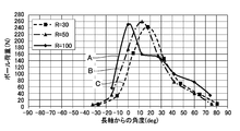
- FIG. 4 shows a measurement example of the distribution state of the load generated at each position in the circumferential direction of the wave generator 4 during load operation when the speed reduction ratio is changed in the wave gear device 1 shown in FIGS. It is a graph.
- a solid curve A, an alternate long and short dash line curve B, and a dashed curve C are load distribution curves when the reduction ratios are 100, 50, and 30, respectively.
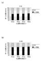
- FIG. 5 is a graph showing the ratio (%) to the load at the major axis position at each angular position from the major axis, (a) is the case where the reduction ratio is 30, and (b) is the reduction ratio. Is 100.
- a load peak appears at a substantially long axis position.
- the load is greatly reduced at an angular position away from the long axis, that is, a position corresponding to an angular position of 35 to 40 degrees where the rollers 53 and 54 and the rollers 55 and 56 are disposed.
- a load peak appears at an angular position shifted by 10 to 20 degrees in the rotational direction with respect to the long axis position.
- the average value of the load acting on the rollers 51 and 52 at the long axis position in both directions is larger than the average value of the load generated at the positions of the remaining rollers 53 to 56. It is effective to make the size of the rollers 51 and 52 in the above larger than the remaining rollers 53 to 56.
- a load peak appears almost at the major axis position, and the load is small at an angular position deviating from the major axis position. Therefore, large rollers 51 and 52 are arranged at the major axis position. In order to improve the life of the wave generator 4, it is very effective to reduce the size of the rollers 53 to 56 arranged at positions deviating from the long axis position.
- a 6-rotor type wave generator is used in a cup-type wave gear device.
- the present invention is also applicable to a wave gear device called a top hat type having a top hat-shaped flexible external gear.
- the present invention is also applicable to a wave gear device called a flat type having a configuration in which cylindrical flexible external gears are coaxially arranged inside two rigid internal gears.
- the present invention can be similarly applied to a roller-type wave generator that includes more rollers than six rollers.
- the present invention can be applied to a wave generator composed of a total of 10 rollers including four pairs of rollers in addition to a pair of rollers on the long axis.
- the pair of rollers on the long axis is the largest size, and the two pairs of rollers arranged on both sides of the pair of rollers are smaller than the rollers on the long axis, and these two pairs of rollers
- the remaining two pairs of rollers disposed on both sides of the roller may be the smallest size.
Abstract
Description
上記の例は、カップ型の波動歯車装置に6ロータータイプの波動発生器を用いた場合のものである。本発明は、シルクハット形状の可撓性外歯歯車を備えたシルクハット型と呼ばれる波動歯車装置に対しても同様に適用可能である。また、2個の剛性内歯歯車の内側に円筒状の可撓性外歯歯車が同軸に配置された構成のフラット型と呼ばれる波動歯車装置に対しても同様に適用可能である。 (Other embodiments)
In the above example, a 6-rotor type wave generator is used in a cup-type wave gear device. The present invention is also applicable to a wave gear device called a top hat type having a top hat-shaped flexible external gear. The present invention is also applicable to a wave gear device called a flat type having a configuration in which cylindrical flexible external gears are coaxially arranged inside two rigid internal gears.
Claims (8)
- 可撓性外歯歯車を予め定めた楕円状の形状に撓めて剛性内歯歯車に部分的に噛み合わせた状態を形成し、回転に伴ってこれら両歯車の噛み合い位置を周方向に移動させて、これら両歯車の歯数差に応じた相対回転をこれら両歯車の間に発生させる波動歯車装置の波動発生器において、
前記可撓性外歯歯車の内周面に当接して当該可撓性外歯歯車を前記楕円状の形状に撓める複数個のローラーを備えており、
前記ローラーには、前記楕円状の形状の長軸上に配置されている2個の第1ローラーと、前記長軸上以外の位置に配置されている第2ローラーとが含まれており、
前記第1ローラーの支持ベアリングのサイズは、前記第2ローラーよりも大きいことを特徴とする波動歯車装置の波動発生器。 The flexible external gear is bent into a predetermined elliptical shape to partially mesh with the rigid internal gear, and the meshing position of both gears is moved in the circumferential direction as it rotates. In the wave generator of the wave gear device that generates a relative rotation between the two gears according to the difference in the number of teeth of both the gears,
A plurality of rollers that contact the inner peripheral surface of the flexible external gear and bend the flexible external gear into the elliptical shape;
The roller includes two first rollers disposed on the major axis of the elliptical shape, and a second roller disposed at a position other than the major axis,
The wave generator of the wave gear device, wherein a size of a support bearing of the first roller is larger than that of the second roller. - 請求項1において、
前記波動歯車装置の負荷運転時に前記ローラーのそれぞれに作用する荷重に基づき、前記第1ローラーの支持ベアリングのサイズおよび前記第2ローラーの支持ベアリングのサイズが設定されていることを特徴とする波動歯車装置の波動発生器。 In claim 1,
The wave gear, wherein the size of the support bearing of the first roller and the size of the support bearing of the second roller are set based on a load acting on each of the rollers during load operation of the wave gear device. Equipment wave generator. - 請求項1または2において、
減速比が80以上の前記波動歯車装置に用いられることを特徴とする波動歯車装置の波動発生器。 In claim 1 or 2,
A wave generator for a wave gear device, wherein the wave generator is used in the wave gear device having a reduction ratio of 80 or more. - 請求項1ないし3のうちのいずれかの項において、
前記ローラーには、前記第1ローラーおよび前記第2ローラーに加えて、少なくとも、2個の第3ローラーが含まれており、
前記第2ローラーのそれぞれは、前記楕円状の形状の中心に対して対称の位置であって、前記楕円状の形状の長軸と短軸の間に配置されており、
前記第3ローラーのそれぞれは、前記長軸を中心として、前記第2ローラーのそれぞれに対して線対称の位置に配置されており、
前記第2ローラーおよび前記第3ローラーは同一サイズの支持ベアリングを備えたローラーであることを特徴とする波動歯車装置の波動発生器。 In any one of claims 1 to 3,
In addition to the first roller and the second roller, the roller includes at least two third rollers,
Each of the second rollers is a symmetric position with respect to the center of the elliptical shape, and is disposed between the major axis and the minor axis of the elliptical shape,
Each of the third rollers is arranged in a line-symmetric position with respect to each of the second rollers around the major axis.
The wave generator of the wave gear device, wherein the second roller and the third roller are rollers having support bearings of the same size. - 剛性内歯歯車と、前記剛性内歯歯車の内側に同軸に配置した半径方向に撓み可能な可撓性外歯歯車と、前記可撓性外歯歯車を楕円状の形状に撓めて当該可撓性外歯歯車を前記楕円状の形状の長軸上の部位において前記剛性内歯歯車に噛み合わせている波動発生器とを有する波動歯車装置において、
前記波動発生器は、前記可撓性外歯歯車の内周面に当接して当該可撓性外歯歯車を前記楕円状の形状に撓めている複数個のローラーを備えており、
前記ローラーには、前記楕円状の形状の長軸上に配置されている2個の第1ローラーと、前記長軸上以外の位置に配置されている第2ローラーとが含まれており、
前記第1ローラーの支持ベアリングのサイズは、前記第2ローラーよりも大きいことを特徴とする波動歯車装置。 A rigid internal gear, a radially externally flexible flexible external gear coaxially disposed inside the rigid internal gear, and the flexible external gear flexed into an elliptical shape. In the wave gear device having a wave generator that meshes the flexible external gear with the rigid internal gear at a portion on the long axis of the elliptical shape,
The wave generator includes a plurality of rollers that are in contact with the inner peripheral surface of the flexible external gear and bend the flexible external gear into the elliptical shape.
The roller includes two first rollers disposed on the major axis of the elliptical shape, and a second roller disposed at a position other than the major axis,
The wave gear device according to claim 1, wherein a size of a support bearing of the first roller is larger than that of the second roller. - 請求項5において、
前記波動歯車装置の負荷運転時に前記ローラーのそれぞれに作用する荷重に基づき、前記第1ローラーの支持ベアリングのサイズおよび前記第2ローラーの支持ベアリングのサイズが設定されていることを特徴とする波動歯車装置。 In claim 5,
The wave gear, wherein the size of the support bearing of the first roller and the size of the support bearing of the second roller are set based on a load acting on each of the rollers during load operation of the wave gear device. apparatus. - 請求項5または6において、
減速比が80以上であることを特徴とする波動歯車装置。 In claim 5 or 6,
A wave gear device having a reduction ratio of 80 or more. - 請求項5ないし7のうちのいずれかの項において、
前記ローラーには、前記第1ローラーの他に、少なくとも、2個の第2ローラーと2個の第3ローラーが含まれており、
前記第2ローラーのそれぞれは、前記楕円状の形状の中心に対して対称の位置であって、前記楕円状の形状の長軸と短軸の間に配置されており、
前記第3ローラーのそれぞれは、前記長軸を中心として、前記第2ローラーのそれぞれに対して線対称の位置に配置されており、
前記第2ローラーおよび前記第3ローラーは同一サイズの支持ベアリングを備えたローラーであることを特徴とする波動歯車装置。 In any one of claims 5 to 7,
In addition to the first roller, the roller includes at least two second rollers and two third rollers,
Each of the second rollers is a symmetric position with respect to the center of the elliptical shape, and is disposed between the major axis and the minor axis of the elliptical shape,
Each of the third rollers is arranged in a line-symmetric position with respect to each of the second rollers around the major axis.
The wave gear device, wherein the second roller and the third roller are rollers having support bearings of the same size.
Priority Applications (6)
| Application Number | Priority Date | Filing Date | Title |
|---|---|---|---|
| CN201280002480.4A CN103582768B (en) | 2012-05-23 | 2012-05-23 | Wave gear apparatus and wave generator for wave gear apparatus |
| PCT/JP2012/003376 WO2013175532A1 (en) | 2012-05-23 | 2012-05-23 | Wave generator for wave gear apparatus |
| DE112012006408.9T DE112012006408T5 (en) | 2012-05-23 | 2012-05-23 | Wave generator for a wave gear |
| JP2013501048A JP5653510B2 (en) | 2012-05-23 | 2012-05-23 | Wave generator of wave gear device |
| KR1020137004855A KR101869727B1 (en) | 2012-05-23 | 2012-05-23 | Wave generator for wave gear device |
| US13/810,846 US9109662B2 (en) | 2012-05-23 | 2012-05-23 | Wave generator for wave gear device |
Applications Claiming Priority (1)
| Application Number | Priority Date | Filing Date | Title |
|---|---|---|---|
| PCT/JP2012/003376 WO2013175532A1 (en) | 2012-05-23 | 2012-05-23 | Wave generator for wave gear apparatus |
Publications (1)
| Publication Number | Publication Date |
|---|---|
| WO2013175532A1 true WO2013175532A1 (en) | 2013-11-28 |
Family
ID=49622048
Family Applications (1)
| Application Number | Title | Priority Date | Filing Date |
|---|---|---|---|
| PCT/JP2012/003376 WO2013175532A1 (en) | 2012-05-23 | 2012-05-23 | Wave generator for wave gear apparatus |
Country Status (6)
| Country | Link |
|---|---|
| US (1) | US9109662B2 (en) |
| JP (1) | JP5653510B2 (en) |
| KR (1) | KR101869727B1 (en) |
| CN (1) | CN103582768B (en) |
| DE (1) | DE112012006408T5 (en) |
| WO (1) | WO2013175532A1 (en) |
Cited By (2)
| Publication number | Priority date | Publication date | Assignee | Title |
|---|---|---|---|---|
| JP2015224684A (en) * | 2014-05-27 | 2015-12-14 | アイシン精機株式会社 | Strain wave gearing |
| EP3412930A4 (en) * | 2016-02-02 | 2019-10-16 | Harmonic Drive Systems Inc. | Strain wave gearing device and actuator |
Families Citing this family (17)
| Publication number | Priority date | Publication date | Assignee | Title |
|---|---|---|---|---|
| WO2014004704A1 (en) | 2012-06-26 | 2014-01-03 | California Institute Of Technology | Systems and methods for implementing bulk metallic glass-based macroscale gears |
| EP3222878B1 (en) * | 2014-11-21 | 2020-05-27 | Harmonic Drive Systems Inc. | Wave generator and wave gear device |
| JP6391187B2 (en) * | 2014-11-28 | 2018-09-19 | 株式会社ハーモニック・ドライブ・システムズ | Lubricating method for wave gear device |
| CN104500689A (en) * | 2014-12-15 | 2015-04-08 | 朱祖良 | Planetary harmonic gear reducer |
| CN107210686B (en) * | 2015-02-13 | 2019-02-19 | 谐波传动系统有限公司 | Wave gear device and wavegenerator |
| CN107709837B (en) * | 2015-04-15 | 2022-04-29 | 詹尼斯机器人技术有限公司 | Wave actuator |
| KR20190119154A (en) | 2017-03-10 | 2019-10-21 | 캘리포니아 인스티튜트 오브 테크놀로지 | Method for manufacturing strain wave gear flexplanes using metal additive manufacturing |
| JP6710809B2 (en) * | 2017-04-28 | 2020-06-17 | 株式会社ハーモニック・ドライブ・システムズ | Wave gear device and wave generator |
| WO2018218077A1 (en) | 2017-05-24 | 2018-11-29 | California Institute Of Technology | Hypoeutectic amorphous metal-based materials for additive manufacturing |
| KR102493233B1 (en) | 2017-06-02 | 2023-01-27 | 캘리포니아 인스티튜트 오브 테크놀로지 | High-toughness metallic glass-based composites for additive manufacturing |
| JP7050559B2 (en) * | 2018-04-16 | 2022-04-08 | 住友重機械工業株式会社 | Flexion meshing gear device |
| US11859705B2 (en) | 2019-02-28 | 2024-01-02 | California Institute Of Technology | Rounded strain wave gear flexspline utilizing bulk metallic glass-based materials and methods of manufacture thereof |
| US11680629B2 (en) * | 2019-02-28 | 2023-06-20 | California Institute Of Technology | Low cost wave generators for metal strain wave gears and methods of manufacture thereof |
| US11591906B2 (en) | 2019-03-07 | 2023-02-28 | California Institute Of Technology | Cutting tool with porous regions |
| KR102215507B1 (en) * | 2019-07-29 | 2021-02-15 | (주)고려기연이엔지 | Hybrid strain wave gear system |
| CN113685528B (en) * | 2021-09-17 | 2023-06-02 | 众合天成智能装备(廊坊)有限公司 | Automatic aligning double-internal-meshing complex wave harmonic drive speed reducer |
| CN116357717B (en) * | 2023-03-07 | 2024-04-05 | 苏州悍猛传动科技有限公司 | Harmonic speed reducer |
Citations (5)
| Publication number | Priority date | Publication date | Assignee | Title |
|---|---|---|---|---|
| JPS5035273Y1 (en) * | 1970-06-16 | 1975-10-14 | ||
| JPS63125247U (en) * | 1987-02-06 | 1988-08-16 | ||
| JPS6425552U (en) * | 1987-08-07 | 1989-02-13 | ||
| JP2007205450A (en) * | 2006-02-01 | 2007-08-16 | Mitsubishi Heavy Ind Ltd | Structure of reduction gear |
| JP2008180259A (en) * | 2007-01-24 | 2008-08-07 | Harmonic Drive Syst Ind Co Ltd | Flat type wave gear device |
Family Cites Families (5)
| Publication number | Priority date | Publication date | Assignee | Title |
|---|---|---|---|---|
| US2906143A (en) * | 1955-03-21 | 1959-09-29 | United Shoe Machinery Corp | Strain wave gearing |
| US2931249A (en) * | 1955-03-21 | 1960-04-05 | United Shoe Machinery Corp | Strain wave gearing-bearing variable elements |
| US4776708A (en) * | 1987-07-17 | 1988-10-11 | Quincy Technologies, Inc. | Extended contact variable ball planetary type wave generator |
| JP2003232411A (en) * | 2002-02-06 | 2003-08-22 | Sofutoronikusu Kk | Motor with gear |
| JP2010190373A (en) * | 2009-02-20 | 2010-09-02 | Harmonic Drive Syst Ind Co Ltd | Wave gear device |
-
2012
- 2012-05-23 JP JP2013501048A patent/JP5653510B2/en active Active
- 2012-05-23 DE DE112012006408.9T patent/DE112012006408T5/en active Pending
- 2012-05-23 US US13/810,846 patent/US9109662B2/en active Active
- 2012-05-23 CN CN201280002480.4A patent/CN103582768B/en active Active
- 2012-05-23 WO PCT/JP2012/003376 patent/WO2013175532A1/en active Application Filing
- 2012-05-23 KR KR1020137004855A patent/KR101869727B1/en active IP Right Grant
Patent Citations (5)
| Publication number | Priority date | Publication date | Assignee | Title |
|---|---|---|---|---|
| JPS5035273Y1 (en) * | 1970-06-16 | 1975-10-14 | ||
| JPS63125247U (en) * | 1987-02-06 | 1988-08-16 | ||
| JPS6425552U (en) * | 1987-08-07 | 1989-02-13 | ||
| JP2007205450A (en) * | 2006-02-01 | 2007-08-16 | Mitsubishi Heavy Ind Ltd | Structure of reduction gear |
| JP2008180259A (en) * | 2007-01-24 | 2008-08-07 | Harmonic Drive Syst Ind Co Ltd | Flat type wave gear device |
Cited By (3)
| Publication number | Priority date | Publication date | Assignee | Title |
|---|---|---|---|---|
| JP2015224684A (en) * | 2014-05-27 | 2015-12-14 | アイシン精機株式会社 | Strain wave gearing |
| EP3412930A4 (en) * | 2016-02-02 | 2019-10-16 | Harmonic Drive Systems Inc. | Strain wave gearing device and actuator |
| TWI704304B (en) * | 2016-02-02 | 2020-09-11 | 日商和諧驅動系統股份有限公司 | Wave gear device and actuator |
Also Published As
| Publication number | Publication date |
|---|---|
| KR20150011744A (en) | 2015-02-02 |
| CN103582768A (en) | 2014-02-12 |
| US20130316867A1 (en) | 2013-11-28 |
| CN103582768B (en) | 2017-02-15 |
| JP5653510B2 (en) | 2015-01-14 |
| JPWO2013175532A1 (en) | 2016-01-12 |
| US9109662B2 (en) | 2015-08-18 |
| DE112012006408T5 (en) | 2015-03-12 |
| KR101869727B1 (en) | 2018-06-21 |
Similar Documents
| Publication | Publication Date | Title |
|---|---|---|
| JP5653510B2 (en) | Wave generator of wave gear device | |
| JP5335152B1 (en) | Wave generator of wave gear device | |
| JP5968545B2 (en) | Wave gear device, friction engagement type wave device, and wave generator | |
| JP5925387B2 (en) | Wave generator and wave gear device | |
| US9309921B2 (en) | Internally-toothed gear unit with composite roller bearing, and wave gear device | |
| WO2015001974A1 (en) | Strain wave gear device | |
| JP6218691B2 (en) | Dual type wave gear device | |
| JP2011190826A (en) | Wave motion gear device | |
| JP6351724B2 (en) | Flat wave gear device | |
| WO2016013379A1 (en) | Dual-type wave gear device | |
| JP6602504B2 (en) | Wave generator and wave gear device | |
| JP2013199948A5 (en) | ||
| TW201920844A (en) | Wave bearing for strain wave gearing | |
| JP6370624B2 (en) | Dual type wave gear device | |
| JP2019065958A (en) | Dual type wave gear device | |
| WO2017022062A1 (en) | Strain wave gearing device | |
| JP6599682B2 (en) | Planetary gear set | |
| JP6632341B2 (en) | Wave gear device with traction drive mechanism | |
| JP2016196895A (en) | Flat-type wave gear device | |
| TWI551791B (en) | Harmonic generator and harmonic gear device |
Legal Events
| Date | Code | Title | Description |
|---|---|---|---|
| ENP | Entry into the national phase |
Ref document number: 2013501048 Country of ref document: JP Kind code of ref document: A |
|
| WWE | Wipo information: entry into national phase |
Ref document number: 13810846 Country of ref document: US |
|
| ENP | Entry into the national phase |
Ref document number: 20137004855 Country of ref document: KR Kind code of ref document: A |
|
| 121 | Ep: the epo has been informed by wipo that ep was designated in this application |
Ref document number: 12877439 Country of ref document: EP Kind code of ref document: A1 |
|
| WWE | Wipo information: entry into national phase |
Ref document number: 1120120064089 Country of ref document: DE Ref document number: 112012006408 Country of ref document: DE |
|
| 122 | Ep: pct application non-entry in european phase |
Ref document number: 12877439 Country of ref document: EP Kind code of ref document: A1 |