JP6632341B2 - Wave gear device with traction drive mechanism - Google Patents
Wave gear device with traction drive mechanism Download PDFInfo
- Publication number
- JP6632341B2 JP6632341B2 JP2015222402A JP2015222402A JP6632341B2 JP 6632341 B2 JP6632341 B2 JP 6632341B2 JP 2015222402 A JP2015222402 A JP 2015222402A JP 2015222402 A JP2015222402 A JP 2015222402A JP 6632341 B2 JP6632341 B2 JP 6632341B2
- Authority
- JP
- Japan
- Prior art keywords
- wave generator
- wave
- gear
- bearing
- drive mechanism
- Prior art date
- Legal status (The legal status is an assumption and is not a legal conclusion. Google has not performed a legal analysis and makes no representation as to the accuracy of the status listed.)
- Active
Links
- 238000005096 rolling process Methods 0.000 claims description 48
- 230000002093 peripheral effect Effects 0.000 claims description 22
- 239000003638 chemical reducing agent Substances 0.000 description 2
- 230000004323 axial length Effects 0.000 description 1
- 239000000470 constituent Substances 0.000 description 1
- 230000008878 coupling Effects 0.000 description 1
- 238000010168 coupling process Methods 0.000 description 1
- 238000005859 coupling reaction Methods 0.000 description 1
- 238000005520 cutting process Methods 0.000 description 1
- 238000004519 manufacturing process Methods 0.000 description 1
- 230000036316 preload Effects 0.000 description 1
Images

Landscapes
- Retarders (AREA)
- Friction Gearing (AREA)
Description
本発明は、低減速比の波動歯車装置に関し、特に、転がり軸受け型のトラクションドライブ機構を用いて低減速比を実現した波動歯車装置に関する。 The present invention relates to a wave gear device having a reduced speed ratio, and more particularly, to a wave gear device that realizes a reduced speed ratio by using a rolling bearing type traction drive mechanism.
波動歯車装置は、入出力部材が同軸上に位置し、一段で高減速比が得られ、高トルク容量、優れた位置決め精度および優れた回転精度を備えている。現行の波動歯車装置の減速比は、一般に1/30〜1/160である。 The wave gear device has an input / output member located coaxially, provides a high reduction ratio in one step, and has a high torque capacity, excellent positioning accuracy, and excellent rotational accuracy. The reduction ratio of the current wave gear device is generally 1/30 to 1/160.
近年、波動歯車装置については、それが組み込まれるアクチュエータの更なる高速動作が求められ、その低速比化の要求が増している。波動歯車装置の低速比化を図るためには、現行の波動歯車装置の速比を利用して、内歯車(サーキュラスプライン)の歯数を、外歯車(フレックスプライン)に対して4枚差、6枚差などにする手法がある。この場合には、内歯車を別に、設計する必要がある。 In recent years, with respect to the wave gear device, further high-speed operation of an actuator into which the wave gear device is incorporated has been demanded, and the demand for a lower speed ratio has been increasing. In order to achieve a lower speed ratio of the wave gear device, the speed ratio of the current wave gear device is used to reduce the number of teeth of the internal gear (circular spline) by four to the external gear (flex spline). There is a method of making a difference of six sheets. In this case, it is necessary to design the internal gear separately.
一方、減速機構としてはトラクションドライブ機構が知られている。トラクションドライブ機構としては、特許文献1に記載されているような遊星ローラ型のトラクションドライブ機構が提案されている。また、転がり軸受け型のトラクションドライブ機構も知られている。
On the other hand, a traction drive mechanism is known as a speed reduction mechanism. As a traction drive mechanism, a planetary roller type traction drive mechanism as described in
ここで、波動歯車装置の低減速比化を実現するに当たっては、現行の波動歯車装置の内歯車の歯数を変えずに、その優れた特性を維持しつつ、低減速比化を実現できることが望ましい。 Here, in realizing the reduction gear ratio of the wave gear device, it is necessary to realize the reduction gear ratio while maintaining the excellent characteristics without changing the number of teeth of the internal gear of the current wave gear device. desirable.
本発明の課題は、この点に鑑みて、転がり軸受け型のトラクションドライブ機構を利用して、内歯車の歯数を変えることなく低減速比化を実現可能な波動歯車装置を提供することにある。 In view of the above, an object of the present invention is to provide a wave gear device that can realize a reduced speed ratio without changing the number of teeth of an internal gear using a traction drive mechanism of a rolling bearing type. .
上記の課題を解決するために、本発明の波動歯車装置は、
転がり軸受け型のトラクションドライブ機構と、
波動歯車機構と、
を有しており、
前記波動歯車機構は、
剛性の内歯車と、
前記内歯車の内側に同軸に配置されている半径方向に撓み可能な可撓性の外歯車と、
前記外歯車の内側に同軸に装着され、前記外歯車を非円形に撓めて前記内歯車に対して部分的にかみ合わせている波動発生器と、
前記波動発生器の内側に同軸に配置されている回転軸と、
を有しており、
前記波動発生器は、
支持軸受けを介して、前記回転軸によって回転自在の状態に支持されている剛性の波動発生器プラグと、
前記波動発生器プラグの非円形外周面と前記外歯車の外歯形成部分の内周面との間にはめ込まれている波動発生器軸受けと、
を備えており、
前記波動発生器軸受は、前記トラクションドライブ機構であり、
前記波動発生器軸受は、
前記外歯形成部分の内周面に嵌めた外輪と、
前記波動発生器プラグの前記非円形外周面に嵌めた内輪と、
前記外輪および前記内輪の間に転動自在の状態に装着されている転動体と、
前記転動体を転動自在の状態で所定の角度間隔に保持し、前記回転軸と一体回転する転動体保持器と、
を備えている。
In order to solve the above problems, the wave gear device of the present invention is:
A rolling bearing type traction drive mechanism ,
A wave gear mechanism ,
Has ,
The wave gear mechanism,
A rigid internal gear,
A radially flexible, flexible external gear coaxially disposed inside the internal gear;
A wave generator mounted coaxially inside the external gear and flexing the external gear non-circularly to partially mesh with the internal gear;
A rotating shaft arranged coaxially inside the wave generator,
Has,
The wave generator,
A rigid wave generator plug rotatably supported by the rotating shaft via a support bearing,
A wave generator bearing fitted between the non-circular outer peripheral surface of the wave generator plug and the inner peripheral surface of the external gear forming portion of the external gear;
With
The wave generator bearing is the traction drive mechanism,
The wave generator bearing,
An outer ring fitted on the inner peripheral surface of the outer tooth forming portion,
An inner ring fitted on the non-circular outer peripheral surface of the wave generator plug,
A rolling element mounted in a freely rolling state between the outer ring and the inner ring;
A rolling element holder that holds the rolling elements at a predetermined angular interval in a freely rotatable state, and integrally rotates with the rotating shaft;
It has.
転がり軸受け型のトラクションドライブ機構は、一般に、その転動体保持器を出力要素として用いた減速機として利用されている。本発明においては、トラクションドライブ機構を増速機として利用している。すなわち、転動体保持器を回転入力要素とし、内輪を回転出力要素としている。トラクションドライブ機構からの増速回転出力が波動歯車機構の波動発生器に伝達される。増速分だけ、波動歯車機構の減速比が低くなる。 A rolling bearing type traction drive mechanism is generally used as a speed reducer using the rolling element holder as an output element. In the present invention, the traction drive mechanism is used as a gearbox. That is, the rolling element retainer is used as a rotation input element, and the inner ring is used as a rotation output element. The speed increased rotation output from the traction drive mechanism is transmitted to the wave generator of the wave gear mechanism. The speed reduction ratio of the wave gear mechanism is reduced by the increased speed.
例えば、波動歯車機構として、減速比が1/30の現行の波動歯車減速機を使用する。トラクションドライブ機構の転動体保持器に、モータなどから高速回転を入力する。トラクションドライブ機構が例えば2.5倍の増速を得る転動体軸受け構造であるとすると、波動歯車機構の波動発生器の回転は、入力回転に対して2.5倍に増速される。この結果、波動歯車装置の全体の減速比は、1/12となる。よって、低減速比の波動歯車装置が得られる。 For example, a current wave gear reducer having a reduction ratio of 1/30 is used as the wave gear mechanism. High-speed rotation is input from a motor or the like to the rolling element holder of the traction drive mechanism. Assuming that the traction drive mechanism has, for example, a rolling element bearing structure capable of increasing the speed by 2.5 times, the rotation of the wave generator of the wave gear mechanism is increased by 2.5 times the input rotation. As a result, the overall reduction ratio of the wave gear device is 1/12. Therefore, a wave gear device having a reduced speed ratio can be obtained.
本発明によれば、波動歯車機構の構成歯車の歯数を変えることなく、波動歯車機構の特性(高トルク容量、優れた位置きめ精度、優れた回転精度)を維持しつつ、従来に比べて低減速比の波動歯車装置を実現できる。 According to the present invention, while maintaining the characteristics (high torque capacity, excellent positioning accuracy, and excellent rotational accuracy) of the wave gear mechanism without changing the number of teeth of the constituent gears of the wave gear mechanism, A wave gear device with a low reduction ratio can be realized.
ここで、転動体保持器に入力軸部を一体形成して、当該入力軸部にモータ回転軸などの回転軸を連結して、回転を入力すればよい。 Here, the input shaft portion may be integrally formed with the rolling element retainer, and a rotation shaft such as a motor rotation shaft may be connected to the input shaft portion to input the rotation.
この場合、波動歯車機構とトラクションドライブ機構を、それらの軸線の方向に配列する場合には、波動歯車装置の全体の軸長が長くなる。したがって、本発明においては、トラクションドライブ機構を波動歯車機構に一体化した構造を採用している。 In this case, when the wave gear mechanism and the traction drive mechanism are arranged in the direction of their axes, the overall shaft length of the wave gear device becomes longer. Therefore, the present invention employs a structure in which the traction drive mechanism is integrated with the wave gear mechanism.
すなわち、本発明の波動歯車装置においては、転動体保持器の入力軸部の外周面に、支持軸受けを介して、波動発生器を回転自在の状態で支持する。また、波動発生器を、非円形の外周面を備えた剛性のプラグと、当該プラグの外周面に装着されて非円形に撓められている波動発生器軸受けとから構成する。そして、波動発生器軸受けにおける外輪、内輪、および、転動体を、それぞれ、トラクションドライブ機構の外輪、内輪および転動体として用いる。 That is, in the wave gear device of the present invention, the wave generator is rotatably supported on the outer peripheral surface of the input shaft portion of the rolling element holder via the support bearing. Further, the wave generator includes a rigid plug having a non-circular outer peripheral surface and a wave generator bearing mounted on the outer peripheral surface of the plug and bent in a non-circular shape. Then, the outer ring, the inner ring, and the rolling element of the wave generator bearing are used as the outer ring, the inner ring, and the rolling element of the traction drive mechanism, respectively.
波動歯車機構において、波動発生器の波動発生器軸受けは、そのプラグによって非円形に撓められ、外歯車を内歯車に対して部分的にかみ合わせている。両歯車のかみ合い位置に対応する部位に位置する波動発生器軸受けの転動体は、半径方向に予圧が掛かった状態にある。したがって、波動発生器軸受けの転動体保持器を回転入力要素とすることにより、当該波動発生器軸受けを、そのまま、トラクションドライブ機構として機能させることができる。 In a wave gear mechanism, the wave generator bearing of the wave generator is flexed non-circularly by its plug, partially engaging the external gear with the internal gear. The rolling element of the wave generator bearing located at a position corresponding to the meshing position of both gears is in a state where a preload is applied in the radial direction. Therefore, by using the rolling element holder of the wave generator bearing as the rotation input element, the wave generator bearing can function as it is as a traction drive mechanism.
以下に、図面を参照して、本発明を適用した波動歯車装置の実施の形態を説明する。 Hereinafter, embodiments of a wave gear device to which the present invention is applied will be described with reference to the drawings.
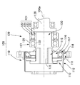
図1(a)は実施の形態1に係る波動歯車装置を、その中心軸線に直交する平面で切断した場合の横断面を示す横断面図であり、図1(b)はその中心軸線を含む平面で切断した場合の縦断面を示す縦断面図である。
FIG. 1A is a cross-sectional view showing a cross section when the wave gear device according to
波動歯車装置1は、波動歯車機構2と、当該波動歯車機構2に組み込まれたトラクションドライブ機構3とから構成されている。波動歯車機構2は、円環形状をしている剛性の内歯車11と、この内側に同軸に配置したカップ形状をした可撓性の外歯車12と、この内側に同軸に嵌めた波動発生器13とを備えている。本例では、波動発生器13によって外歯車12は楕円状に撓められ、その楕円形状の長軸L1の位置において内歯車11にかみ合っている。
The
なお、本例では、カップ形状の外歯車12を備えた波動歯車機構2を用いているが、シルクハット形状の外歯車を備えた波動歯車機構であってもよい。また、2枚の内歯車の内側に円筒状の外歯車が配置され、一方の内歯車から減速回転が出力されるフラット型と呼ばれる波動歯車機構であってもよい。さらに、本例では、波動発生器13によって外歯車12を楕円状に撓めて、円周方向の2箇所の位置で両歯車11、12をかみ合わせている。外歯車を非円形に撓めて3箇所以上の位置で内歯車にかみ合わせるようにしてもよい。
In this example, the
波動歯車機構2において、波動発生器13が回転すると、両歯車11、12のかみ合い位置が円周方向に移動する。波動発生器13が1回転すると、両歯車11、12の歯数差分だけ両歯車の間に相対回転が生じる。例えば、内歯車11が回転しないように固定され、外歯車12が不図示の負荷部材の側に連結される。この場合には、波動発生器13の回転が歯数差に応じて減速されて、外歯車12から不図示の負荷部材に出力される。
In the
外歯車12は、半径方向に撓み可能な円筒状胴部14と、この後端から半径方向の内方に延びるダイヤフラム15と、このダイヤフラム15の内周縁に連続して形成されている円環形状をした剛性のボス16を備えている。円筒状胴部14の前端開口の側の部分は外歯形成部分17であり、その外周面に外歯18が形成されている。
The
波動発生器13は外歯車12の外歯形成部分17の内側にはめ込まれている。波動発生器13は、筒形状をした剛性の波動発生器プラグ21と、この波動発生器プラグ21の楕円状外周面22に装着して楕円状に撓められている波動発生器軸受け23とを備えている。また、波動発生器13は、波動発生器プラグ21の中空部に同軸に配置した中空回転軸(保持器入力軸)24を備えており、中空回転軸24は、その外周面に取り付けたボール軸受けからなる支持軸受け25を介して、波動発生器プラグ21を回転自在の状態で支持している。
The
波動発生器軸受け23は、外歯車12の外歯形成部分17の内周面19に嵌めた外輪26と、波動発生器プラグ21の楕円状外周面22に嵌めた内輪27と、これら外輪26および内輪27の間の軌道に転動自在の状態で装着されている複数個の転動体28と、転動体28を円周方向において一定の角度間隔で回転自在に保持している転動体保持器30とを備えている。
The wave generator bearing 23 includes an
転動体保持器30は、中空回転軸24の外側の軸端部24aに一体形成されており、当該軸端部24aから半径方向の外方に広がる円盤状の腕部31(あるいは放射状に延びる複数本の腕部31)と、腕部31の外周端部から直角に折れ曲がって、各転動体28の間に差し込まれている複数の転動体保持部32とを備えている。隣接する転動体保持部32の間に、各転動体28が回転自在の状態に保持されるので、各転動体28は、外輪26、内輪27の軌道面に沿って転動自在である。
The rolling
本例では、波動発生器軸受け23としてボール軸受けを用いている。波動発生器軸受け23としては、ローラ軸受けなどの各種の軸受けを用いることができる。
In this example, a ball bearing is used as the
波動歯車機構2において、その波動発生器軸受け23は波動発生器プラグ21によって楕円状に撓められており、楕円形状の長軸L1の付近に位置する転動体28は半径方向に予圧が掛かった状態になる。したがって、波動発生器軸受け23の転動体保持器30を回転入力要素とすることで、波動発生器軸受け23はそのままトラクションドライブ機構3として機能する。
In the
波動歯車装置1において、転動体保持器30が一体形成されている中空回転軸24を回転させると、トラクションドライブ機構3として機能する波動発生器軸受け23の内輪27が増速回転する。したがって、内輪27が装着されている楕円状の波動発生器プラグ21も増速回転する。例えば、波動発生器軸受け23の構成部品の寸法を設定して、増速比が2.5のトラクションドライブ機構3を構成しておく。
In the
2.5倍の速度で回転する波動発生器プラグ21によって、波動歯車機構2の両歯車11、12のかみ合い位置が円周方向に移動して、両歯車11、12の間に生じる相対回転が、外歯車12から不図示の負荷側に出力される。波動歯車機構2の減速比を現行の波動歯車装置で実現可能な1/30であるとする。この場合には、中空回転軸24に入力される回転は、トラクションドライブ機構3によって2.5倍に増速された後に、1/30に減速される。減速回転出力要素である外歯車12からは、入力回転が1/12に減速された回転が取り出される。よって、1/12の低減速比の波動歯車装置を実現できる。
The meshing position of the two
(参考例)
図2は、トラクションドライブ機構を備えた波動歯車装置の参考例を示す縦断面図である。波動歯車装置100は、波動歯車機構110とトラクションドライブ機構120とが、中心軸線100aの方向にタンデムに連結されている。波動歯車装置100の軸長は大きくなるが、トラクションドライブ機構120の増速比の設計が容易である。
(Reference example)
FIG. 2 is a longitudinal sectional view showing a reference example of a wave gear device provided with a traction drive mechanism. In the
波動歯車機構110は、一般的な波動歯車機構と同様であり、剛性の内歯車111と、この内側に同軸に配置した可撓性の外歯車112と、外歯車112の内側に嵌めた楕円状輪郭の波動発生器113とを備えている。外歯車112は例えばカップ形状をしており、その外歯形成部分114の内側に波動発生器113が装着されている。
The
波動発生器113は、円筒状のハブ115と、このハブ115の外周面にオルダム継ぎ手を介して装着されている波動発生器プラグ116と、波動発生器プラグ116の楕円状外周面に装着した波動発生器軸受け117とを備えている。
The
トラクションドライブ機構120は、転がり軸受け型の機構であり、その転がり軸受け部121は、外輪122と、内輪123と、これらの間に転動自在の状態で装着されている複数個の転動体124と、転動体124を円周方向に等角度間隔で回転自在の状態に保持している転動体保持器125とを備えている。転動体保持器125には同軸に保持器入力軸126が一体形成されている。
The
トラクションドライブ機構120の転がり軸受け部121における波動歯車機構110の側には支持軸受け127が同軸に配置されている。転がり軸受け部121の内輪123および支持軸受け127の内輪128には、出力軸130がはめ込まれている。転がり軸受け部121の外輪122および支持軸受け127の外輪129は、不図示の装置ハウジングなどの固定側部材に固定されており、出力軸130は、転がり軸受け部121および支持軸受け127を介して、回転自在の状態で、不図示の固定側部材によって支持されている。
A support bearing 127 is coaxially disposed on the side of the
トラクションドライブ機構120の出力軸130における波動歯車機構110の側に軸端面には同軸に小径の軸連結部131が延びている。軸連結部131は、波動歯車機構110のハブ115の中心軸穴に装着されて、ハブ115と一体回転するように同軸に連結されている。
A small diameter
波動歯車装置100において、トラクションドライブ機構120の保持器入力軸126を回転させると、出力軸130が増速回転する。増速回転は、出力軸130に連結されている波動歯車機構110の波動発生器113に入力される。波動発生器113が回転すると、両歯車111、112のかみ合い位置が円周方向に移動し、両歯車の間に歯数差に応じた相対回転が生じる。例えば、内歯車111が固定され、外歯車112から減速回転が不図示の負荷側に出力される。
In the
トラクションドライブ機構120によって増速された回転が波動歯車機構110によって減速されて、負荷側に出力される。したがって、現行の波動歯車機構を用いて、低速比の波動波動歯車減速装置を実現できる。
The rotation speed increased by the
1 波動歯車装置
2 波動歯車機構
3 トラクションドライブ機構
11 内歯車
12 外歯車
13 波動発生器
14 円筒状胴部
15 ダイヤフラム
16 ボス
17 外歯形成部分
18 外歯
19 内周面
21 波動発生器プラグ
22 楕円状外周面
23 波動発生器軸受け
24 中空回転軸(保持器入力軸)
24a 軸端部
25 支持軸受け
26 外輪
27 内輪
28 転動体
30 転動体保持器
31 腕部
32 転動体保持部
L1 長軸
DESCRIPTION OF
24a
Claims (1)
波動歯車機構と、
を有しており、
前記波動歯車機構は、
剛性の内歯車と、
前記内歯車の内側に同軸に配置されている半径方向に撓み可能な可撓性の外歯車と、
前記外歯車の内側に同軸に装着され、前記外歯車を非円形に撓めて前記内歯車に対して部分的にかみ合わせている波動発生器と、
前記波動発生器の内側に同軸に配置されている回転軸と、
を有しており、
前記波動発生器は、
支持軸受けを介して、前記回転軸によって回転自在の状態に支持されている剛性の波動発生器プラグと、
前記波動発生器プラグの非円形外周面と前記外歯車の外歯形成部分の内周面との間にはめ込まれている波動発生器軸受けと、
を備えており、
前記波動発生器軸受は、前記トラクションドライブ機構であり、
前記波動発生器軸受は、
前記外歯形成部分の内周面に嵌めた外輪と、
前記波動発生器プラグの前記非円形外周面に嵌めた内輪と、
前記外輪および前記内輪の間に転動自在の状態に装着されている転動体と、
前記転動体を転動自在の状態で所定の角度間隔に保持し、前記回転軸と一体回転する転動体保持器と、
を備えている波動歯車装置。 A rolling bearing type traction drive mechanism,
A wave gear mechanism,
Has,
The wave gear mechanism,
A rigid internal gear,
A radially flexible, flexible external gear coaxially disposed inside the internal gear;
A wave generator mounted coaxially inside the external gear and flexing the external gear non-circularly to partially mesh with the internal gear;
A rotating shaft arranged coaxially inside the wave generator,
Has,
The wave generator,
A rigid wave generator plug rotatably supported by the rotating shaft via a support bearing,
A wave generator bearing fitted between the non-circular outer peripheral surface of the wave generator plug and the inner peripheral surface of the external gear forming portion of the external gear;
With
The wave generator bearing is the traction drive mechanism,
The wave generator bearing,
An outer ring fitted on the inner peripheral surface of the outer tooth forming portion,
An inner ring fitted on the non-circular outer peripheral surface of the wave generator plug;
A rolling element mounted in a freely rolling state between the outer ring and the inner ring;
A rolling element holder that holds the rolling elements at a predetermined angular interval in a freely rotatable state, and integrally rotates with the rotating shaft;
A wave gear device comprising:
Priority Applications (2)
| Application Number | Priority Date | Filing Date | Title |
|---|---|---|---|
| JP2015222402A JP6632341B2 (en) | 2015-11-12 | 2015-11-12 | Wave gear device with traction drive mechanism |
| CN201620439332.4U CN205780620U (en) | 2015-11-12 | 2016-05-16 | There is the Wave gear device of traction drive mechanism |
Applications Claiming Priority (1)
| Application Number | Priority Date | Filing Date | Title |
|---|---|---|---|
| JP2015222402A JP6632341B2 (en) | 2015-11-12 | 2015-11-12 | Wave gear device with traction drive mechanism |
Publications (3)
| Publication Number | Publication Date |
|---|---|
| JP2017089804A JP2017089804A (en) | 2017-05-25 |
| JP2017089804A5 JP2017089804A5 (en) | 2018-10-18 |
| JP6632341B2 true JP6632341B2 (en) | 2020-01-22 |
Family
ID=57409509
Family Applications (1)
| Application Number | Title | Priority Date | Filing Date |
|---|---|---|---|
| JP2015222402A Active JP6632341B2 (en) | 2015-11-12 | 2015-11-12 | Wave gear device with traction drive mechanism |
Country Status (2)
| Country | Link |
|---|---|
| JP (1) | JP6632341B2 (en) |
| CN (1) | CN205780620U (en) |
Families Citing this family (1)
| Publication number | Priority date | Publication date | Assignee | Title |
|---|---|---|---|---|
| KR102105346B1 (en) * | 2019-07-18 | 2020-04-28 | 이종희 | Reducer |
Family Cites Families (7)
| Publication number | Priority date | Publication date | Assignee | Title |
|---|---|---|---|---|
| JPS499534B1 (en) * | 1967-11-29 | 1974-03-05 | ||
| JPS5129418Y1 (en) * | 1970-01-29 | 1976-07-24 | ||
| JPS5620858A (en) * | 1979-03-30 | 1981-02-26 | Sony Corp | Roller bearing |
| JPS5846252A (en) * | 1981-09-16 | 1983-03-17 | Kanae Komiyama | Roller bearing type multistage transmission |
| JPS6425552U (en) * | 1987-08-07 | 1989-02-13 | ||
| JPH0241692U (en) * | 1988-09-14 | 1990-03-22 | ||
| JP2007225035A (en) * | 2006-02-23 | 2007-09-06 | Harmonic Drive Syst Ind Co Ltd | Multistage wave motion gear device |
-
2015
- 2015-11-12 JP JP2015222402A patent/JP6632341B2/en active Active
-
2016
- 2016-05-16 CN CN201620439332.4U patent/CN205780620U/en active Active
Also Published As
| Publication number | Publication date |
|---|---|
| CN205780620U (en) | 2016-12-07 |
| JP2017089804A (en) | 2017-05-25 |
Similar Documents
| Publication | Publication Date | Title |
|---|---|---|
| JP5925387B2 (en) | Wave generator and wave gear device | |
| JP5064300B2 (en) | Wave gear type linear motion mechanism | |
| US9163710B2 (en) | Wave gear device and flexible externally toothed gear | |
| WO2015001974A1 (en) | Strain wave gear device | |
| JP3186812U (en) | Variable speed transmission bearing | |
| WO2013175533A1 (en) | Wave generators for wave gear apparatus | |
| WO2013175532A1 (en) | Wave generator for wave gear apparatus | |
| EP3425777B1 (en) | Compound harmonic gear | |
| JP3187367U (en) | Cup-type wave gear unit | |
| JP2011190826A (en) | Wave motion gear device | |
| JP2017203546A (en) | Driving device | |
| EP3680513A1 (en) | Wave bearing for wave-motion gear device | |
| US20190113107A1 (en) | Compound planetary gear assembly | |
| WO2012036033A1 (en) | Planetary gear device | |
| JP5480845B2 (en) | Planetary gear mechanism | |
| JP6632341B2 (en) | Wave gear device with traction drive mechanism | |
| JP5906764B2 (en) | Gear device | |
| JP2017223246A (en) | Wave gear transmission | |
| WO2017022062A1 (en) | Strain wave gearing device | |
| JP2017150573A (en) | Speed reducer | |
| EP3719349A1 (en) | Wave gear device | |
| KR20180115878A (en) | Two-stage harmonic drive | |
| JP6369274B2 (en) | Inscribed mesh planetary gear mechanism | |
| JP2012127422A (en) | Planetary gear mechanism | |
| JP2020051541A (en) | Gear speed reducer |
Legal Events
| Date | Code | Title | Description |
|---|---|---|---|
| A521 | Request for written amendment filed |
Free format text: JAPANESE INTERMEDIATE CODE: A523 Effective date: 20180904 |
|
| A621 | Written request for application examination |
Free format text: JAPANESE INTERMEDIATE CODE: A621 Effective date: 20180904 |
|
| A977 | Report on retrieval |
Free format text: JAPANESE INTERMEDIATE CODE: A971007 Effective date: 20190724 |
|
| A131 | Notification of reasons for refusal |
Free format text: JAPANESE INTERMEDIATE CODE: A131 Effective date: 20190730 |
|
| A521 | Request for written amendment filed |
Free format text: JAPANESE INTERMEDIATE CODE: A523 Effective date: 20190902 |
|
| TRDD | Decision of grant or rejection written | ||
| A01 | Written decision to grant a patent or to grant a registration (utility model) |
Free format text: JAPANESE INTERMEDIATE CODE: A01 Effective date: 20191210 |
|
| A61 | First payment of annual fees (during grant procedure) |
Free format text: JAPANESE INTERMEDIATE CODE: A61 Effective date: 20191210 |
|
| R150 | Certificate of patent or registration of utility model |
Ref document number: 6632341 Country of ref document: JP Free format text: JAPANESE INTERMEDIATE CODE: R150 |
|
| R250 | Receipt of annual fees |
Free format text: JAPANESE INTERMEDIATE CODE: R250 |
|
| R250 | Receipt of annual fees |
Free format text: JAPANESE INTERMEDIATE CODE: R250 |