WO2013172015A1 - 球技用ボール - Google Patents
球技用ボール Download PDFInfo
- Publication number
- WO2013172015A1 WO2013172015A1 PCT/JP2013/003057 JP2013003057W WO2013172015A1 WO 2013172015 A1 WO2013172015 A1 WO 2013172015A1 JP 2013003057 W JP2013003057 W JP 2013003057W WO 2013172015 A1 WO2013172015 A1 WO 2013172015A1
- Authority
- WO
- WIPO (PCT)
- Prior art keywords
- ball
- spherical surface
- conductive
- sphere
- spherical
- Prior art date
- Legal status (The legal status is an assumption and is not a legal conclusion. Google has not performed a legal analysis and makes no representation as to the accuracy of the status listed.)
- Ceased
Links
Images







Classifications
-
- A—HUMAN NECESSITIES
- A63—SPORTS; GAMES; AMUSEMENTS
- A63B—APPARATUS FOR PHYSICAL TRAINING, GYMNASTICS, SWIMMING, CLIMBING, OR FENCING; BALL GAMES; TRAINING EQUIPMENT
- A63B43/00—Balls with special arrangements
- A63B43/004—Balls with special arrangements electrically conductive, e.g. for automatic arbitration
-
- A—HUMAN NECESSITIES
- A63—SPORTS; GAMES; AMUSEMENTS
- A63B—APPARATUS FOR PHYSICAL TRAINING, GYMNASTICS, SWIMMING, CLIMBING, OR FENCING; BALL GAMES; TRAINING EQUIPMENT
- A63B37/00—Solid balls; Rigid hollow balls; Marbles
- A63B37/0003—Golf balls
-
- A—HUMAN NECESSITIES
- A63—SPORTS; GAMES; AMUSEMENTS
- A63B—APPARATUS FOR PHYSICAL TRAINING, GYMNASTICS, SWIMMING, CLIMBING, OR FENCING; BALL GAMES; TRAINING EQUIPMENT
- A63B37/00—Solid balls; Rigid hollow balls; Marbles
- A63B37/0003—Golf balls
- A63B37/0038—Intermediate layers, e.g. inner cover, outer core, mantle
-
- A—HUMAN NECESSITIES
- A63—SPORTS; GAMES; AMUSEMENTS
- A63B—APPARATUS FOR PHYSICAL TRAINING, GYMNASTICS, SWIMMING, CLIMBING, OR FENCING; BALL GAMES; TRAINING EQUIPMENT
- A63B37/00—Solid balls; Rigid hollow balls; Marbles
- A63B37/0003—Golf balls
- A63B37/0038—Intermediate layers, e.g. inner cover, outer core, mantle
- A63B37/0039—Intermediate layers, e.g. inner cover, outer core, mantle characterised by the material
-
- A—HUMAN NECESSITIES
- A63—SPORTS; GAMES; AMUSEMENTS
- A63B—APPARATUS FOR PHYSICAL TRAINING, GYMNASTICS, SWIMMING, CLIMBING, OR FENCING; BALL GAMES; TRAINING EQUIPMENT
- A63B45/00—Apparatus or methods for manufacturing balls
-
- A—HUMAN NECESSITIES
- A63—SPORTS; GAMES; AMUSEMENTS
- A63B—APPARATUS FOR PHYSICAL TRAINING, GYMNASTICS, SWIMMING, CLIMBING, OR FENCING; BALL GAMES; TRAINING EQUIPMENT
- A63B47/00—Devices for handling or treating balls, e.g. for holding or carrying balls
- A63B47/008—Devices for measuring or verifying ball characteristics
-
- A—HUMAN NECESSITIES
- A63—SPORTS; GAMES; AMUSEMENTS
- A63B—APPARATUS FOR PHYSICAL TRAINING, GYMNASTICS, SWIMMING, CLIMBING, OR FENCING; BALL GAMES; TRAINING EQUIPMENT
- A63B2220/00—Measuring of physical parameters relating to sporting activity
- A63B2220/30—Speed
- A63B2220/34—Angular speed
- A63B2220/35—Spin
-
- A—HUMAN NECESSITIES
- A63—SPORTS; GAMES; AMUSEMENTS
- A63B—APPARATUS FOR PHYSICAL TRAINING, GYMNASTICS, SWIMMING, CLIMBING, OR FENCING; BALL GAMES; TRAINING EQUIPMENT
- A63B2220/00—Measuring of physical parameters relating to sporting activity
- A63B2220/30—Speed
- A63B2220/36—Speed measurement by electric or magnetic parameters
-
- A—HUMAN NECESSITIES
- A63—SPORTS; GAMES; AMUSEMENTS
- A63B—APPARATUS FOR PHYSICAL TRAINING, GYMNASTICS, SWIMMING, CLIMBING, OR FENCING; BALL GAMES; TRAINING EQUIPMENT
- A63B2220/00—Measuring of physical parameters relating to sporting activity
- A63B2220/80—Special sensors, transducers or devices therefor
- A63B2220/89—Field sensors, e.g. radar systems
-
- A—HUMAN NECESSITIES
- A63—SPORTS; GAMES; AMUSEMENTS
- A63B—APPARATUS FOR PHYSICAL TRAINING, GYMNASTICS, SWIMMING, CLIMBING, OR FENCING; BALL GAMES; TRAINING EQUIPMENT
- A63B24/00—Electric or electronic controls for exercising apparatus of preceding groups; Controlling or monitoring of exercises, sportive games, training or athletic performances
- A63B24/0021—Tracking a path or terminating locations
Definitions
- the present invention relates to a ball for ball games.
- a device using a Doppler radar has been used as a measuring device for measuring ball game balls, particularly golf ball launch conditions (initial velocity, launch angle, spin amount) and ballistic measurement.
- a transmission wave composed of a microwave is emitted from the antenna toward the golf ball, the reflected wave reflected by the golf ball is measured, and the moving speed and spin are calculated based on the Doppler signal obtained from the transmission wave and the reflected wave. Find the amount.
- obtaining the reflected wave efficiently is advantageous in securing the measurement distance.
- Patent Documents 1, 2, and 3 a technique for providing a layer or film containing a metal material over the entire surface of the ball has been proposed in order to improve appearance and design.
- Patent Document 4 a technique for providing a spherical metal layer is provided between a core layer of a ball and a cover.
- the layer or film containing a metal material when the layer or film containing a metal material is formed in a spherical shape on the entire surface of the ball, it is advantageous in securing radio wave reflection characteristics, but the spin amount of the ball was insufficient to secure the measurement distance.
- the present invention has been made in view of such circumstances, and an object thereof is to provide a ball game ball that is advantageous in accurately and accurately measuring launch conditions and ballistics, and a method for manufacturing the same. It is in.
- the ball game ball of the present invention has a sphere, and an intersecting surface that intersects a spherical surface centered on the center of the sphere and is located inside the outer surface of the sphere,
- the intersection surface is formed as a conductive intersection surface having conductivity.
- the transmission wave emitted from the antenna of the measuring device using the Doppler radar is efficiently reflected by the conductive intersection plane that moves with the rotation of the ball for ball game, so that the spin amount in the Doppler signal is detected. Therefore, it is possible to secure the signal intensity of the frequency distribution necessary for this purpose, to detect the spin amount stably and surely, which is advantageous in accurately measuring the launch conditions and ballistics accurately. .
- FIG. It is a block diagram explaining the measurement principle of a ball game ball using Doppler radar. It is explanatory drawing of the principle which detects the spin amount of a golf ball. It is explanatory drawing which simplifies and shows the result of having performed the wavelet analysis of the Doppler signal Sd at the time of measuring the hit golf ball with the Doppler radar 10.
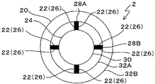
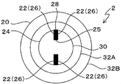
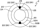
- FIG. It is explanatory drawing which shows the signal strength distribution data P which shows signal strength distribution for every frequency obtained by frequency-analyzing the Doppler signal Sd in the time t1 in FIG. It is sectional drawing of the golf ball 2 in 1st Embodiment. It is sectional drawing of the golf ball 2 in 2nd Embodiment. It is sectional drawing of the golf ball 2 in 3rd Embodiment.
- FIG. 5 is a cross-sectional view illustrating dimensions of each part of a golf ball 2 in Example 2.
- FIG. 10 is a diagram showing experimental results of Experimental Examples 10 to 16 in Example 2.
- the Doppler radar 10 includes an antenna 12 and a Doppler sensor 14.
- reference numeral 2 indicates a golf ball as a ball for ball game
- 4 indicates a golf club head
- 6 indicates a shaft
- 8 indicates a golf club.
- the antenna 12 transmits a microwave as a transmission wave W ⁇ b> 1 toward the golf ball 2 based on the transmission signal supplied from the Doppler sensor 14, and receives the reflected wave W ⁇ b> 2 reflected by the golf ball 2 and receives the received signal. Is supplied to the Doppler sensor 14.
- the Doppler sensor 14 supplies a transmission signal to the antenna 12.
- the Doppler signal Sd having the Doppler frequency Fd is generated as time series data based on the received signal supplied from the antenna 12.
- the Doppler signal Sd is a signal having a Doppler frequency Fd defined by a frequency F1-F2 that is a difference between the frequency F1 of the transmission signal and the frequency F2 of the reception signal.
- Various commercially available Doppler sensors 14 can be used. For example, a 24 GHz microwave can be used as the transmission signal, and the frequency of the transmission signal is not limited as long as the Doppler signal Sd can be obtained.
- the Doppler frequency Fd is expressed by Expression (1).
- V speed of the golf ball 2
- c speed of light (3 ⁇ 10 8 m / s) Therefore, when equation (1) is solved for V, equation (2) is obtained.
- V c ⁇ Fd / (2 ⁇ F1) (2) That is, the velocity V of the golf ball 2 is proportional to the Doppler frequency Fd. Therefore, the frequency component of the Doppler frequency Fd can be detected from the Doppler signal Sd, and the velocity V of the golf ball 2 can be obtained from the detected Doppler frequency component based on Expression (2).
- FIG. 2 is an explanatory diagram of the principle of detecting the spin amount of the golf ball.
- the transmission wave W1 is efficiently reflected at the first portion A, which is the surface portion where the angle formed with the transmission direction of the transmission wave W1 is close to 90 degrees.
- the strength of W2 is high.
- the transmission wave W1 is not efficiently reflected in the second part B and the third part C, which are parts of the surface of the golf ball whose surface makes an angle with the transmission direction of the transmission wave W1 close to 0 degrees.
- the intensity of the reflected wave W2 is low.
- the second part B is a part in which the direction of rotation by the spin of the golf ball 2 is opposite to the moving direction of the golf ball.
- the third portion C is a portion in which the direction rotated by the spin of the golf ball 2 is the same as the moving direction of the golf ball.
- the velocity detected based on the reflected wave W2 reflected by the first portion A is the first partial velocity Va
- the velocity detected based on the reflected wave W2 reflected by the second portion B is the second partial velocity Vb
- a velocity detected based on the reflected wave W2 reflected by the third portion C is defined as a third partial velocity Vc.
- Va V ⁇ (3)
- Vb Va- ⁇ r (4)
- Vc Va + ⁇ r (5) (Where V ⁇ is the moving speed of the golf ball 2, ⁇ is the angular velocity (rad / s), and r is the radius of the golf ball 2).
- the moving speed V ⁇ of the golf ball 2 can be calculated from the first partial speed Va based on the formula (3), and the second and third parts can be calculated based on the formula (4) or the formula (5). Since the angular velocity ⁇ is obtained from the velocities Vb and Vc, the spin amount can be calculated from the angular velocity ⁇ .
- the Doppler radar does not calculate the moving speed V ⁇ and the spin amount based on the above formula, but shows the distribution of the signal intensity for each frequency by frequency analysis of the Doppler signal Sd as described below. It is possible to generate the signal intensity distribution data P and obtain the moving speed V ⁇ and the spin amount from the signal intensity distribution data P.
- FIG. 3 is an explanatory view showing a simplified result of wavelet analysis of the Doppler signal Sd when the hit golf ball is measured by the Doppler radar 10.
- the horizontal axis represents time t (ms), and the vertical axis represents the Doppler frequency Fd (kHz) and the velocity V (m / s) of the golf ball 2.
- Such a diagram can be obtained, for example, by sampling the Doppler signal Sd, taking it into a digital oscilloscope and converting it into digital data, and then performing wavelet analysis or continuous FFT analysis on the digital data using a personal computer or the like. .
- the frequency distribution indicated by the symbol DA is a portion corresponding to the first partial speed Va with a strong signal strength.
- the frequency distribution indicated by the symbol DB has a lower signal intensity than the frequency distribution DA and corresponds to the second partial speed Vb.
- the frequency distribution indicated by the reference sign DC is a portion corresponding to the third partial velocity Vc having a signal intensity lower than the frequency distribution DA.
- FIG. 4 is an explanatory diagram showing signal intensity distribution data P indicating a signal intensity distribution for each frequency obtained by frequency analysis of the Doppler signal Sd at time t1 in FIG.
- the horizontal axis represents velocity V (m / s)
- the vertical axis represents signal intensity Ps (arbitrary unit). Note that the velocity V on the horizontal axis is proportional to the frequency of the Doppler signal Sd.
- the thin line represents the measured value of the signal intensity distribution data P
- the thick line represents the moving average of the measured value of the signal intensity distribution data P. That is, since the actual measurement value of the signal intensity distribution data P greatly fluctuates due to the influence of the spin, the data is stabilized by taking the moving average, and the signal intensity distribution data P that can be easily processed later is obtained. ing.
- the signal intensity distribution data P represented by the moving average has one maximum value that maximizes the signal intensity Ps, and the signal intensity gradually decreases as the distance from the maximum value increases.
- the peak of the signal intensity distribution data P that is, the maximum value Dmax of the signal intensity Ps corresponds to the value of the first partial speed Va.
- the value of the Doppler frequency corresponding to the maximum value Dmax of the signal strength Ps corresponds to the value of the first partial velocity Va. Therefore, the higher the Doppler frequency corresponding to the maximum value Dmax, the faster the first partial speed Va, that is, the moving speed of the golf ball 2.
- the width of the peak of the signal intensity distribution data P is proportional to the difference ⁇ V (speed width) between the second partial speed Vb and the third partial speed Vc. Therefore, the smaller the difference ⁇ V between the second partial speed Vb and the third partial speed Vc, the smaller the spin amount. Therefore, if the difference ⁇ V is zero, the spin amount is zero. Further, the larger the difference ⁇ V between the second partial speed Vb and the third partial speed Vc, the larger the spin amount.
- the difference ⁇ V between the second partial velocity Vb and the third partial velocity Vc is expressed by the following equation (6) as can be seen from the equations (4) and (5), that is, a value proportional to the angular velocity ⁇ . It becomes.
- the width of the mountain can be defined as follows.
- the width of the peak of the signal intensity distribution data P is such that when the threshold Dt of the signal intensity signal intensity Ps is Dmax ⁇ N (where 0 ⁇ N ⁇ 1), the signal intensity Ps of the signal intensity distribution data P is the threshold Dt. Is the width of the part.
- the golf ball is actually hit to measure the data of the maximum value Dmax and the moving speed V ⁇ , and the data of the peak width and the spin amount Sp of the signal intensity distribution data P are measured. Then, a correlation map between the maximum value Dmax and the moving speed V ⁇ and a correlation map between the peak width of the signal intensity distribution data P and the spin amount Sp are created from these actual measurement results.
- the moving speed V ⁇ can be obtained from the maximum value Dmax
- the spin amount Sp can be obtained from the width of the peak of the signal intensity distribution data P. Therefore, it is important to reliably measure the maximum value Dmax when obtaining the moving speed V ⁇ using such a measurement principle.
- the spin amount Sp it is important to reliably measure the width of the peak of the signal intensity distribution data P.
- the signal intensity of the reflected wave W2 received by the antenna 12 decreases, and the signal intensity of each frequency distribution DA, DB, DC Each decrease.
- the signal strengths of the frequency distribution DB and DC of the Doppler signal Sd shown in FIG. 3 are originally weaker than the signal strength of the frequency distribution DA, the signal strengths of the frequency distribution DB and DC are measured stably. There are disadvantages.
- the signal strength of the frequency distribution DB and DC that can be received by the antenna 12 cannot be received in a shorter time than the signal strength of the frequency distribution DA, the time during which the signal strength of the frequency distribution DB and DC can be measured is There is also the disadvantage of a very limited period. For this reason, it is difficult to reliably measure the width of the peak of the signal intensity distribution data P, which is disadvantageous in obtaining an accurate spin amount Sp. Therefore, there is a demand for a golf ball 2 that can reliably and stably receive the signal intensity of the frequency distribution DB and DC of the reflected wave W2 reflected by the golf ball 2 with the antenna 12.
- FIG. 5 is a sectional view of the golf ball 2 according to the first embodiment.
- the golf ball 2 includes a sphere 20 and an intersecting surface 22.
- the intersecting surface 22 intersects the spherical surface 24 centered on the center of the sphere 20 and is located inside the outer surface of the sphere 20, and the intersecting surface 22 is formed as a conductive intersecting surface 26 having conductivity.
- the spherical surface 24 is formed with a diameter smaller than the diameter of the sphere 20, and the conductive intersection surface 26 is formed on the radially outer side of the spherical surface 24.
- annular body 28 (first annular body) made of a conductive material is formed on the entire circumference of the spherical surface 24 that intersects the plane passing through the center of the spherical surface 24.
- the conductive material various conventionally known materials such as a conductive resin, a conductive elastomer, a conductive cloth, and a conductive fiber can be used.
- the annular body 28 has a rectangular cross section.
- the conductive intersection surface 26 is formed on the side surfaces on both sides of the annular body 28, and thus the conductive intersection surface 26 is continuously formed over the entire circumference of the spherical surface 24 in the circumferential direction.
- the radio wave reflectance ⁇ can be measured by a conventionally known method such as a waveguide method or a free space method.
- the golf ball 2 includes a spherical solid core layer 30 and a cover layer 32 that covers the core layer 30.
- the sphere 20 is composed of the core layer 30 and the cover layer 32, and the spherical surface 24 is the surface (outer surface) of the core layer 30.
- the core layer 30 is made of a conventionally known material such as synthetic rubber.
- the core layer 30 may be composed of a single core layer 30 or may be composed of two or more core layers 30.
- various conventionally known synthetic resins can be used for the cover layer 32. A large number of dimples are formed on the surface of the cover layer 32.
- the tip end surface of the annular body 28 located on the radially outer side of the sphere 20 is exposed on the surface of the cover layer 32.
- a crossing surface 22 that intersects the spherical surface 24 centered on the center of the sphere 20 is formed as a conductive crossing surface 26 having conductivity. Therefore, the transmission wave W ⁇ b> 1 emitted from the antenna 12 of the Doppler radar 10 is reflected by the conductive intersection surface 26 that moves with the rotation of the golf ball 2. Therefore, it is advantageous in securing the radio wave intensity of the reflected wave W2. That is, as shown in FIG. 2, the conductive intersection surface 26 is located at a position corresponding to the second portion B and the third portion C, which are portions of the surface whose angle formed with the transmission direction of the transmission wave W1 is close to 0 degrees.
- the transmission wave W1 is efficiently reflected by the conductive intersection surface 26, so that the strength of the reflected wave W2 can be ensured. Therefore, even if the hit golf ball 2 is separated from the antenna 12 and the signal intensity of the reflected wave W2 received by the antenna 12 is decreased, the signal intensity of each frequency distribution DB and DC can be ensured. That is, it is possible to secure the signal intensity of the frequency distribution DB and DC necessary for detecting the spin amount Sp in the Doppler signal, which is advantageous in stably detecting the spin amount Sp. Therefore, the spin amount Sp can be stably measured over a longer period.
- the Doppler radar 10 when the Doppler radar 10 is applied to a golf simulator apparatus installed indoors, it is sufficient even if the output of the transmission wave W1 is low or the S / N ratio is not sufficiently obtained. Frequency distribution DB and DC having signal strength can be obtained. Therefore, the ball simulator and the flight distance can be accurately calculated based on the spin amount Sp in addition to the initial speed and launch angle of the golf ball 2 by the golf simulator device, and a more accurate simulation reflecting the spin amount Sp is performed. Can do. Specifically, the flight distance can be more accurately simulated by reflecting the spin amount Sp.
- FIG. 6 is a cross-sectional view of the golf ball 2 according to the second embodiment.
- the second embodiment is a modification of the first embodiment, and is different from the first embodiment in that two annular bodies are provided. Otherwise, the second embodiment is the same as the first embodiment. It is the same.
- the same parts and members as those in the first embodiment are denoted by the same reference numerals, and the description thereof is omitted.
- the golf ball 2 includes a sphere 20 and an intersection surface 22.
- a first annular body 28A made of a conductive material is formed on the entire circumference of the spherical surface 24 that intersects the first plane passing through the center of the spherical surface 24 so as to protrude.
- a second annular body 28B made of a conductive material protrudes from the entire circumference of the spherical surface 24 that passes through the center of the spherical surface 24 and intersects the second plane orthogonal to the first plane.
- the conductive intersection surface 26 is formed on the side surfaces on both sides of the first annular body 28 and the second annular body 28B. Therefore, similarly to the first embodiment, the conductive intersection surface 26 is continuously formed over the entire length of the circumferential surface of the spherical surface 24.
- the first annular body 28A and the second annular body 28B have a rectangular cross section, and the first annular body 28A and the second annular body 28B located on the radially outer side of the sphere 20 have a rectangular shape.
- the tip surface is exposed on the surface of the cover layer 32.
- the same effect as that of the first embodiment can be obtained.
- the frequency with which the reflected wave W2 is generated can be increased as compared with the first embodiment. . Therefore, the reflected wave W2 can be received more stably, which is more advantageous for stably and surely detecting the spin amount Sp, and for stably measuring the spin amount Sp over a long period of time. Even more advantageous.
- FIG. 7 is a cross-sectional view of the golf ball 2 according to the third embodiment.
- the third embodiment is different from the first embodiment in that the conductive intersection surface 26 is provided.
- the golf ball 2 includes a sphere 20 and an intersection surface 22.
- the intersecting surface 22 intersects the spherical surface 24 centered on the center of the sphere 20, and the intersecting surface 22 is formed as a conductive intersecting surface 26 having conductivity.
- the spherical surface 24 is formed with a diameter smaller than the diameter of the sphere 20, and the conductive intersection surface 26 is formed on the radially inner side of the spherical surface 24.
- a concave groove 25 (first concave groove) is formed on the entire circumference of the spherical surface 24 that intersects a plane passing through the center of the spherical surface 24.
- An annular body 28 (first annular body) is formed by embedding a conductive material in the concave groove 25.
- the conductive intersection surface 26 is formed on the side surfaces on both sides of the annular body 28, and thus the conductive intersection surface 26 is continuously formed over the entire circumference of the spherical surface 24 in the circumferential direction.
- the annular body 28 has a rectangular cross section. More specifically, the golf ball 2 includes a spherical solid core layer 30 and a cover layer 32 that covers the core layer 30.
- the spherical body 20 includes the core layer 30, and the spherical surface 24 includes the core layer 30. 30 surface (outer surface).
- the tip end surface of the annular body 28 located on the radially outer side of the sphere 20 is exposed on the surface of the core layer 30.
- the same effect as that of the first embodiment can be obtained.
- FIG. 8 is a cross-sectional view of the golf ball 2 according to the second embodiment.
- the fourth embodiment is a modification of the third embodiment, and is different from the third embodiment in that two annular bodies are provided. Other than that, the fourth embodiment is different from the third embodiment. It is the same.
- the golf ball 2 includes a sphere 20 and an intersection surface 22.
- a first groove 25 ⁇ / b> A is formed on the entire circumference of the spherical surface 24 that intersects the first plane passing through the center of the spherical surface 24.
- a first annular body 28A is formed by embedding a conductive material in the first concave groove 25A.
- a second concave groove 25B is formed on the entire circumference of the spherical surface 24 that passes through the center of the spherical surface 24 and intersects with a second plane that is orthogonal to the first plane.
- a second annular body 28B is formed by embedding a conductive material in the second concave groove 25B.
- the conductive intersection surface 26 is formed on both side surfaces of the first annular body 28A and the second annular body 28B. Therefore, as in the second embodiment, the conductive intersection surface 26 is continuously formed over the entire length of the circumferential surface of the spherical surface 24.
- the first annular body 28A and the second annular body 28B have a rectangular cross section, and the first annular body 28A and the second annular body 28B located on the radially outer side of the sphere 20 have a rectangular shape.
- the tip surface is exposed on the surface of the core layer 30.
- the same effect as that of the third embodiment can be obtained.
- the frequency with which the reflected wave W2 is generated can be increased as compared with the third embodiment. . Therefore, the reflected wave W2 can be received more stably, which is more advantageous for stably and surely detecting the spin amount Sp, and for stably measuring the spin amount Sp over a long period of time. Even more advantageous.
- FIG. 9 is a sectional view of the golf ball 2 according to the fifth embodiment.
- the fifth embodiment differs from the first embodiment in that the conductive intersection surface 26 is provided.
- the golf ball 2 includes a sphere 20 and an intersection surface 22.
- the intersecting surface 22 intersects the spherical surface 24 centered on the center of the sphere 20, and the intersecting surface 22 is formed as a conductive intersecting surface 26 having conductivity.
- the spherical surface 24 is formed with a diameter smaller than the diameter of the sphere 20, and the conductive intersection surface 26 is formed on the radially outer side of the spherical surface 24.
- An annular body 28 made of a conductive material is formed on the entire circumference of the spherical surface 24 that intersects the plane passing through the center of the spherical surface 24.
- the conductive intersection surface 26 is formed on the side surfaces on both sides of the annular body 28, and thus the conductive intersection surface 26 is continuously formed over the entire circumference of the spherical surface 24 in the circumferential direction.
- the annular body 28 has a rectangular cross section. More specifically, the sphere 20 is formed of a spherical and solid core layer 30, and a first cover layer 32A and a second cover layer 32B that cover the core layer 30.
- the first cover layer 32 ⁇ / b> A and the second cover layer 32 ⁇ / b> B constitute a plurality of layers that cover the core layer 30.
- the first cover layer 32 ⁇ / b> A and the second cover layer 32 ⁇ / b> B are made of a material that allows passage of radio waves so that the radio waves are reflected by the conductive intersection surface 26.
- a large number of dimples are formed on the surface of the second cover layer 32B.
- the spherical surface 24 is formed on the surface of the first cover layer 32A.
- the tip end surface of the annular body 28 located on the radially outer side of the sphere 20 is exposed on the surface of the second cover layer 32B.
- the same effect as that of the first embodiment can be obtained.
- FIG. 10 is a cross-sectional view of the golf ball 2 according to the sixth embodiment.
- the sixth embodiment is a modification of the fifth embodiment, and is different from the fifth embodiment in that two annular bodies are provided. Other than that, the sixth embodiment is the same as the fifth embodiment. It is the same.
- the golf ball 2 includes a sphere 20 and an intersection surface 22.
- a first annular body 28A made of a conductive material is formed on the entire circumference of the spherical surface 24 that intersects the first plane passing through the center of the spherical surface 24 so as to protrude.
- a second annular body 28B made of a conductive material protrudes from the entire circumference of the spherical surface 24 that passes through the center of the spherical surface 24 and intersects the second plane orthogonal to the first plane.
- the conductive intersection surface 26 is formed on both side surfaces of the first annular body 28A and the second annular body 28B. Therefore, the conductive intersection surface 26 is continuously formed over the entire length of the entire circumference in the circumferential direction of the spherical surface 24.
- the first annular body 28A and the second annular body 28B have a rectangular cross section.
- the sphere 20 is formed of a spherical and solid core layer 30, and a first cover layer 32A and a second cover layer 32B that cover the core layer 30.
- the first cover layer 32 ⁇ / b> A and the second cover layer 32 ⁇ / b> B are made of a material that allows passage of radio waves so that the radio waves are reflected by the conductive intersection surface 26.
- the spherical surface 24 is formed on the surface of the first cover layer 32A.
- the tip surfaces of the first annular body 28A and the second annular body 28B located on the radially outer side of the sphere 20 are exposed on the surface of the second cover layer 32B.
- the same effect as that of the first embodiment can be obtained.
- the frequency of occurrence of the reflected wave W2 can be increased as compared with the fifth embodiment. . Therefore, the reflected wave W2 can be received more stably, which is more advantageous for stably and surely detecting the spin amount Sp, and for stably measuring the spin amount Sp over a long period of time. Even more advantageous.
- FIG. 11 is a cross-sectional view of the golf ball 2 according to the seventh embodiment.
- the seventh embodiment is a modification of the sixth embodiment, and the sixth embodiment is that the first annular body 28A and the second annular body 28B are covered with the second cover layer 32B.
- the first annular body 28A and the second annular body 28B have a rectangular cross section, and the first annular body 28A and the second annular body that are located radially outside the spherical body 20 The tip surface of 28B is covered with a second cover layer 32B.
- the same effects as in the sixth embodiment can be obtained.
- FIG. 12 is a cross-sectional view of the golf ball 2 according to the eighth embodiment.
- the eighth embodiment is a modification of the fifth embodiment, and is different from the fifth embodiment in that the conductive intersection surface 26 is provided.
- the golf ball 2 includes a sphere 20 and an intersection surface 22.
- the intersecting surface 22 intersects the spherical surface 24 centered on the center of the sphere 20, and the intersecting surface 22 is formed as a conductive intersecting surface 26 having conductivity.
- the spherical surface 24 is formed with a diameter smaller than the diameter of the sphere 20, and the conductive intersection surface 26 is formed on the radially outer side of the spherical surface 24.
- An annular body 28 made of a conductive material is formed on the entire circumference of the spherical surface 24 that intersects the plane passing through the center of the spherical surface 24.
- the conductive intersection surface 26 is formed on the side surfaces on both sides of the annular body 28, and thus the conductive intersection surface 26 is continuously formed over the entire circumference of the spherical surface 24 in the circumferential direction.
- the annular body 28 has a rectangular cross section. More specifically, the sphere 20 is formed of a spherical and solid core layer 30, and a first cover layer 32A and a second cover layer 32B that cover the core layer 30. The spherical surface 24 is formed on the surface of the core layer 30.
- the tip end surface of the annular body 28 located on the radially outer side of the sphere 20 is exposed on the surface of the first cover layer 32A and is covered with the second cover layer 32B.
- the same effect as that of the first embodiment is achieved.
- FIG. 13 is a cross-sectional view of the golf ball 2 according to the ninth embodiment.
- the ninth embodiment is a modification of the eighth embodiment, and is different from the eighth embodiment in that two annular bodies are provided. Other than that, the ninth embodiment is the same as the eighth embodiment. It is the same.
- the golf ball 2 includes a sphere 20 and an intersection surface 22.
- a first annular body 28A made of a conductive material is formed on the entire circumference of the spherical surface 24 that intersects the first plane passing through the center of the spherical surface 24 so as to protrude.
- a second annular body 28B made of a conductive material protrudes from the entire circumference of the spherical surface 24 that passes through the center of the spherical surface 24 and intersects the second plane orthogonal to the first plane.
- the conductive intersection surface 26 is formed on the side surfaces on both sides of the first annular body 28 and the second annular body 28B. Therefore, the conductive intersection surface 26 is continuously formed over the entire length of the entire circumference in the circumferential direction of the spherical surface 24.
- the first annular body 28A and the second annular body 28B have a rectangular cross section, and the first annular body 28A and the second annular body 28B located on the radially outer side of the sphere 20 have a rectangular shape.
- the leading end surface is exposed on the surface of the first cover layer 32A and is covered with the second cover layer 32B. More specifically, the sphere 20 is formed by a spherical and solid core layer 30, and a first cover layer 32 A and a second cover layer 32 B that cover the core layer 30, and the spherical surface 24 is formed of the core layer 30. It is formed on the surface.
- the same effect as that of the first embodiment is obtained.
- the frequency with which the reflected wave W2 is generated can be increased as compared with the eighth embodiment. . Therefore, the reflected wave W2 can be received more stably, which is more advantageous for stably and surely detecting the spin amount Sp, and for stably measuring the spin amount Sp over a long period of time. Even more advantageous.
- FIG. 14 is a cross-sectional view of the golf ball 2 according to the tenth embodiment.
- the tenth embodiment is a modification of the ninth embodiment, and differs from the ninth embodiment in that the conductive intersection surface 26 is provided.
- the golf ball 2 includes a sphere 20 and an intersection surface 22.
- a first groove 25 ⁇ / b> A is formed on the entire circumference of the spherical surface 24 that intersects the first plane passing through the center of the spherical surface 24.
- a first annular body 28A is formed by embedding a conductive material in the first concave groove 25A.
- a second concave groove 25B is formed on the entire circumference of the spherical surface 24 that passes through the center of the spherical surface 24 and intersects with a second plane that is orthogonal to the first plane.
- a second annular body 28B is formed by embedding a conductive material in the second concave groove 25B.
- the conductive intersection surface 26 is formed on both side surfaces of the first annular body 28A and the second annular body 28B. Therefore, the conductive intersection surface 26 is continuously formed over the entire length of the entire circumference in the circumferential direction of the spherical surface 24.
- the first annular body 28A and the second annular body 28B have a rectangular cross section.
- the sphere 20 is formed of a spherical solid core layer 30 and a first cover layer 32A and a second cover layer 32B that cover the core layer 30, and the spherical surface 24 is a first cover layer. It is formed on the surface of the layer 32A.
- the tip surfaces of the first annular body 28A and the second annular body 28B located on the radially outer side of the sphere 20 are exposed on the surface of the first cover layer 32A, and the second cover layer 32B. Covered with.
- the same effect as in the ninth embodiment can be obtained.
- FIG. 15 is a cross-sectional view of the golf ball 2 according to the eleventh embodiment.
- the eleventh embodiment differs from the first embodiment in that the conductive intersection surface 26 is provided.
- the golf ball 2 includes a sphere 20 and an intersection surface 22.
- a concave groove 25 is formed on the entire circumference of the spherical surface 24 that intersects a plane passing through the center of the spherical surface 24.
- An annular body 28 (first annular body) is formed by embedding a conductive material in the concave groove 25.
- the conductive intersection surface 26 is formed on both side surfaces of the annular body 28.
- the conductive intersection surface 26 is continuously formed over the entire length of the entire circumference in the circumferential direction of the spherical surface 24.
- the annular body 28 has a rectangular cross section. More specifically, the sphere 20 is formed by a spherical and solid core layer 30, and a first cover layer 32 A and a second cover layer 32 B that cover the core layer 30, and the spherical surface 24 is formed of the core layer 30. It is formed on the surface.
- the first cover layer 32 ⁇ / b> A and the second cover layer 32 ⁇ / b> B are made of a material that allows passage of radio waves so that the radio waves are reflected by the conductive intersection surface 26.
- the tip end surface of the annular body 28 located on the radially outer side of the sphere 20 is exposed on the surface of the core layer 30 and is covered with the first cover layer 32A. Even in the eleventh embodiment, the same effects as in the first embodiment can be obtained.
- FIG. 16 is a cross-sectional view of the golf ball 2 according to the twelfth embodiment.
- the twelfth embodiment is a modification of the eleventh embodiment, and is different from the tenth embodiment in that two annular bodies are provided. Other than that, the twelfth embodiment is different from the tenth embodiment. It is the same.
- the golf ball 2 includes a sphere 20 and an intersection surface 22.
- a first groove 25 ⁇ / b> A is formed on the entire circumference of the spherical surface 24 that intersects the first plane passing through the center of the spherical surface 24.
- a first annular body 28A is formed by embedding a conductive material in the first concave groove 25A.
- a second concave groove 25B is formed on the entire circumference of the spherical surface 24 that passes through the center of the spherical surface 24 and intersects with a second plane that is orthogonal to the first plane.
- a second annular body 28B is formed by embedding a conductive material in the second concave groove 25B.
- the conductive intersection surface 26 is formed on both side surfaces of the first annular body 28A and the second annular body 28B. Therefore, the conductive intersection surface 26 is continuously formed over the entire length of the entire circumference in the circumferential direction of the spherical surface 24.
- the annular body 28 has a rectangular cross section. More specifically, the sphere 20 is formed by a spherical and solid core layer 30, and a first cover layer 32 A and a second cover layer 32 B that cover the core layer 30, and the spherical surface 24 is formed of the core layer 30. It is formed on the surface. In the present embodiment, the tip surfaces of the first annular body 28A and the second annular body 28B located on the radially outer side of the sphere 20 are exposed on the surface of the core layer 30, and are covered with the first cover layer 32A. ing. In the twelfth embodiment, the same effects as those in the eleventh embodiment are exhibited.
- the frequency of occurrence of the reflected wave W2 can be increased as compared with the eleventh embodiment. . Therefore, the reflected wave W2 can be received more stably, which is more advantageous for stably and surely detecting the spin amount Sp, and for stably measuring the spin amount Sp over a long period of time. Even more advantageous.
- FIG. 17 is a cross-sectional view of the golf ball 2 according to the thirteenth embodiment.
- the thirteenth embodiment is a modification of the eighth embodiment shown in FIG. 12, and the cross-sectional shape of the annular body 28 is different from that of the eighth embodiment. Otherwise, the eighth embodiment is the same. It is the same.
- the golf ball 2 includes a sphere 20 and an intersection surface 22.
- a concave groove 25 is formed on the entire circumference of the spherical surface 24 that intersects a plane passing through the center of the spherical surface 24.
- An annular body 28 (first annular body) is formed by embedding a conductive material in the concave groove 25.
- the conductive intersection surface 26 is formed on both side surfaces of the annular body 28. Therefore, the conductive intersection surface 26 is continuously formed over the entire length of the entire circumference in the circumferential direction of the spherical surface 24.
- the cross section of the annular body 28 has a trapezoidal shape whose width becomes narrower toward the outer side in the radial direction of the sphere 20. More specifically, the sphere 20 is formed of a spherical solid core layer 30 and a first cover layer 32A and a second cover layer 32B that cover the core layer 30, and the spherical surface 24 is a first cover layer. It is formed on the surface of the layer 32A.
- the tip end surface of the annular body 28 located on the radially outer side of the sphere 20 is exposed on the surface of the first cover layer 32A and is covered with the second cover layer 32B.
- the same effect as that of the first embodiment is achieved.
- FIG. 18 is a cross-sectional view of the golf ball 2 according to the fourteenth embodiment.
- the fourteenth embodiment is a modification of the thirteenth embodiment, and the cross-sectional shape of the annular body 28 is different from that of the thirteenth embodiment.
- the golf ball 2 includes a sphere 20 and an intersection surface 22.
- a concave groove 25 is formed on the entire circumference of the spherical surface 24 that intersects a plane passing through the center of the spherical surface 24.
- An annular body 28 is formed by embedding a conductive material in the concave groove 25.
- the conductive intersection surface 26 is formed on both side surfaces of the annular body 28.
- the conductive intersection surface 26 is continuously formed over the entire length of the entire circumference in the circumferential direction of the spherical surface 24.
- the cross-section of the annular body 28 has an elliptical shape in which the major axis coincides with the radial direction of the sphere 20. More specifically, the sphere 20 is formed of a spherical solid core layer 30 and a first cover layer 32A and a second cover layer 32B that cover the core layer 30, and the spherical surface 24 is a first cover layer. It is formed on the surface of the layer 32A.
- the tip end surface of the annular body 28 located on the radially outer side of the sphere 20 is exposed on the surface of the first cover layer 32A and is covered with the second cover layer 32B.
- the same effects as in the first embodiment can be obtained.
- FIG. 19 is a cross-sectional view of the golf ball 2 according to the fifteenth embodiment.
- the fifteenth embodiment is a modification of the thirteenth embodiment, and the cross-sectional shape of the annular body 28 is different from that of the thirteenth embodiment. Otherwise, the fifteenth embodiment is the same as the thirteenth embodiment.
- the golf ball 2 includes a sphere 20 and an intersection surface 22.
- a concave groove 25 is formed on the entire circumference of the spherical surface 24 that intersects a plane passing through the center of the spherical surface 24.
- An annular body 28 is formed by embedding a conductive material in the concave groove 25.
- the conductive intersection surface 26 is formed on both side surfaces of the annular body 28. Therefore, the conductive intersection surface 26 is continuously formed over the entire length of the entire circumference in the circumferential direction of the spherical surface 24.
- the cross-section of the annular body 28 has a trapezoidal shape that increases in width toward the outer side in the radial direction of the sphere 20, and the conductive intersection surface 26 is formed on a plane passing through the center of the sphere 20.
- the sphere 20 is formed of a spherical solid core layer 30 and a first cover layer 32A and a second cover layer 32B that cover the core layer 30, and the spherical surface 24 is a first cover layer.
- the tip end surface of the annular body 28 located on the radially outer side of the sphere 20 is exposed on the surface of the first cover layer 32A and is covered with the second cover layer 32B.
- the same effects as those in the first embodiment are achieved.
- the conductive intersection surface 26 is formed on a plane passing through the center of the sphere 20. Therefore, as shown in FIG. 2, when the conductive intersection surface 26 is orthogonal to the transmission direction of the transmission wave W1, the reflected wave W2 that reflects the fastest rotation speed of the conductive intersection surface 26 most efficiently. Is obtained. Therefore, the speed difference between the second partial speed Vb and the third partial speed Vc shown in FIG. 2 is increased, and a wider frequency component of the reflected wave W2 can be obtained, and the signal intensity distribution data P in FIG. 4 is stabilized. Therefore, it is advantageous in calculating the spin rate more accurately.
- Example 1 Next, experimental results of the golf ball 2 will be described. In the following, an experiment was conducted on the golf ball 2 of the first embodiment. Examples will be described.
- the experimental conditions are as follows.
- the golf ball 2 is not formed with the conductive intersection surface 26.
- a conductive intersection surface 26 is formed on the golf ball 2, and the height of the conductive intersection surface 26 along the radial direction of the sphere 20 is 0.3 mm.
- a conductive intersection surface 26 is formed on the golf ball 2, and the height of the conductive intersection surface 26 along the radial direction of the sphere 20 is 0.5 mm.
- FIGS. 21A to 21B are diagrams showing signal intensity distribution data Ps in Experimental Examples 1 to 3.
- FIG. 21A to 21B are diagrams showing signal intensity distribution data Ps in Experimental Examples 1 to 3.
- FIGS. 21B and 21C the width of the peak of the waveform of the signal intensity distribution data Ps is secured larger than that in FIG. Further, FIG. 21C has a larger peak width of the waveform of the signal intensity distribution data Ps than FIG. 21B. Therefore, the formation of the conductive intersection surface 26 is advantageous in accurately measuring the spin amount, and the larger the area of the conductive intersection surface 26, the more advantageous in accurately measuring the spin amount. it is obvious.
- the conductive intersection surface 26 is formed along the entire circumference of the spherical surface 24.
- the conductive intersection surface 26 is spaced apart in the circumferential direction of the spherical surface 24. A plurality of them may be formed. Further, the conductive intersection surface 26 does not need to be formed along the circumferential direction of the spherical surface 24, and may be formed irregularly.
- the annular body 28 made of a conductive material is provided and the conductive intersection surface 26 is formed on both side surfaces of the annular body 28 has been described.
- the conductive intersecting surface 26 only needs to intersect the spherical surface 24 centered on the center of the sphere 20, and the present invention uses the annular body 28 made of a conductive material to conduct electricity. It is not limited to the structure which forms the crossing surface 26. FIG. For example, the following configuration may be used. 1) An annular body 28 made of a material having no electrical conductivity is formed on the spherical surface 24 so as to project, and intersecting surfaces 22 are formed on both side surfaces of the annular body 28, and the surface of these intersecting surfaces 22 includes metal powder.
- the conductive intersection surface 26 is formed by applying 2) The conductive intersection surface 26 is formed by bonding a metal foil, a conductive resin, a conductive elastomer, a conductive cloth, and a conductive fiber to the surface of the intersection surface 22. 3) The conductive intersection surface 26 is formed by depositing a conductive material on the surface of the intersection surface 22.
- the configuration of the conductive intersection surface 26 may be the configuration shown in FIGS. 20 (A) to 20 (D).
- the sphere 20 is formed of a spherical solid core layer 30, and a first cover layer 32A and a second cover layer 32B covering the core layer 30, and the spherical surface 24 is formed by the first cover layer 32A. Formed on the surface.
- the position of the spherical surface 24 may be the surface of the second cover layer 32B or the surface of the core layer 30. 1) As shown in FIG.
- one or more concave portions 40 are provided on the spherical surface 24, and a conductive material 46 is formed on the side surface of the concave portion 40, and the conductivity formed on the side surface of the concave portion 40 is increased.
- the conductive intersection surface 26 may be constituted by the material 46 having the same.
- the portion of the recess 40 excluding the conductive intersection surface 26 may have any configuration as long as it does not prevent the transmission wave W ⁇ b> 1 from being reflected by the conductive intersection surface 26.
- the same material as that of the first cover layer 32A or the same material as that of the second cover layer 32B may be filled in the portion of the recess 40 excluding the conductive intersection surface 26. 2) As shown in FIG.
- one or more recesses 40 are provided in the spherical surface 24, and the conductive material is filled in the recesses 40. May be configured.
- one or more convex portions 42 are provided on the spherical surface 24, and a conductive material 46 is formed on the side surface of the convex portion 42, and is formed on the side surface of the convex portion 42.
- the conductive intersection surface 26 may be constituted by a conductive material 46.
- one or more convex portions 42 made of a conductive material 46 are provided on the spherical surface 24, and the conductive intersection surface 26 is constituted by the side surfaces of the convex portions 42. Good. Even in such a modification, the same effects as those of the first embodiment can be obtained.
- Example 2 Next, other experimental results of the golf ball 2 will be described.
- the golf ball 2 has the same structure as that shown in FIG. In this case, as shown in FIG. 22, the distance a along the radial direction of the sphere 20 between the convex portion 42 made of the conductive material 46 and the surface of the second cover layer 32B is 1.3 mm. The width of the convex portion 42 (the interval between the two conductive crossing surfaces 26 facing each other) b is 5 mm.
- Experimental Example 10 corresponds to a comparative example, and the golf ball 2 is not formed with the conductive intersection surface 26.
- the height h of the conductive intersection surface 26 along the radial direction of the sphere 20 was 20 ⁇ m. 20 ⁇ m corresponds to the thickness of a general metal foil.
- the height h was 150 ⁇ m. 150 ⁇ m corresponds to a relatively thick coating film.
- the height h was set to 300 ⁇ m, 500 ⁇ m, 900 ⁇ m, and 1500 ⁇ m.
- Each golf ball 2 configured in this way is adjusted to fly at a rotational speed of 5000 rpm (5000 revolutions per minute) with a golf ball launcher (launcher), and the spin rate is set to 100 using a Doppler radar for each experimental example. The number of spins was measured and the standard deviation of the spin rate was determined.
- the standard deviation of Experimental Example 11 was set to 100, and the standard deviation of each Experimental Example was displayed as an index in inverse proportion. That is, if the standard deviation is 1 ⁇ 2 of the standard deviation of Experimental Example 11, the index is 200. When the index was 200 or more, 200 was described as the upper limit.
- the signal intensity distribution data Ps sufficient to measure the spin amount cannot be obtained, and therefore no index is shown in FIG.
- the spin amount variation index is 113 or more
- the spin amount variation index is 113 or more
- the spin amount variation index is 113 or more
- the spin amount variation index Becomes 200 or more. Therefore, the height h along the radial direction of the sphere 20 of the conductive intersection surface 26 is preferably 200 ⁇ m or more, more preferably 400 ⁇ m or more.
- the upper limit of the height h along the radial direction of the sphere 20 of the conductive intersection surface 26 is appropriately determined by the outer diameters of various balls.
- the outer diameter is about 43 mm, and the upper limit of the height h of the conductive intersection surface 26 along the radial direction of the sphere 20 is appropriately determined by this outer diameter.
- the arrangement and area of the conductive intersection surface 26 can be determined as appropriate in consideration of characteristics such as flight characteristics and symmetry required for the ball.
- the spherical surface 24 is formed with a diameter smaller than the diameter of the sphere 20, and the conductive intersection surface 26 has the spherical surface 24.
- the entire spherical surface 24 excluding the conductive intersection surface 26 may be a conductive spherical surface having conductivity.
- the intensity of the reflected wave W2 on the conductive spherical surface can be increased, which is advantageous in securing the signal intensity of the frequency distribution DA shown in FIG. That is, as shown in FIG. 4, the peak of the signal intensity distribution data P (the maximum value Dmax of the signal intensity Ps) can be measured larger. Therefore, it is advantageous in stably measuring the moving speed of the golf ball 2 over a longer period.
- the case where the single annular body 28 is provided or the case where the two annular bodies 28A and 28B are provided is described.
- the number of the annular bodies is as follows. Three or more may be sufficient.
- the case where a single groove 25 is provided, or the case where two grooves, the first groove 25A and the second groove 25B, are described.
- the number of grooves is as follows. Three or more may be sufficient.
- the ball game ball is the golf ball 2
- the present invention is not limited to the golf ball 2, but is a hard baseball, a soft baseball, a tennis ball, and a soccer ball.
- the present invention can be widely applied to various conventionally known ball games such as balls.
Landscapes
- Health & Medical Sciences (AREA)
- General Health & Medical Sciences (AREA)
- Physical Education & Sports Medicine (AREA)
- Life Sciences & Earth Sciences (AREA)
- Biophysics (AREA)
- Radar Systems Or Details Thereof (AREA)
Description
上記装置では、アンテナからゴルフボールに向けてマイクロ波からなる送信波を発射し、ゴルフボールで反射された反射波を計測し、送信波と反射波から得られるドップラー信号に基づいて移動速度やスピン量を求める。
この場合、移動速度やスピン量を安定して確実に計測するためには、反射波を効率よく得ることが重要である。言い換えると、反射波を効率よく得ることが計測距離を確保する上で有利となる。
また、反発性を確保するために、ボールのコア層とカバーの間に球面状の金属層を設ける技術が提案されている(特許文献4参照)。
本発明は、このような事情に鑑みてなされたものであり、その目的は、打ち出し条件の計測や弾道計測を的確にかつ正確に行う上で有利な球技用ボールおよびその製造方法を提供することにある。
本発明の球技用ボールの実施の形態について説明する前に、ドップラーレーダを用いた球技用ボールの移動速度およびスピン量の測定原理について説明する。
図1に示すように、ドップラーレーダ10は、アンテナ12と、ドップラーセンサ14とを備える。
なお、図1において符号2は球技用ボールとしてのゴルフボール、4はゴルフクラブヘッド、6はシャフト、8はゴルフクラブを示す。
ドップラー信号Sdとは、前記送信信号の周波数F1と前記受信信号の周波数F2との差分の周波数F1-F2で定義されるドップラー周波数Fdを有する信号である。
ドップラーセンサ14は、市販されている種々のものが使用可能である。
なお、前記の送信信号としては、例えば、24GHzのマイクロ波が使用可能であり、ドップラー信号Sdを得られるものであれば送信信号の周波数は限定されない。
従来から知られているように、ドップラー周波数Fdは式(1)で表される。
Fd=F1-F2=2・V・F1/c (1)
ただし、V:ゴルフボール2の速度、c:光速(3・108m/s)
したがって、式(1)をVについて解くと、式(2)となる。
V=c・Fd/(2・F1) (2)
すなわち、ゴルフボール2の速度Vは、ドップラー周波数Fdに比例することになる。
したがって、ドップラー信号Sdからドップラー周波数Fdの周波数成分を検出し、検出したドップラー周波数成分から式(2)に基づいてゴルフボール2の速度Vを求めることができる。
ゴルフボール2の表面のうち、送信波W1の送信方向となす角度が90度に近い表面の部分である第1部分Aでは送信波W1が効率よく反射され、したがって、第1部分Aでは反射波W2の強度が高い。
一方、ゴルフボールの表面のうち、送信波W1の送信方向となす角度が0度に近い表面の部分である第2部分B、第3部分Cでは送信波W1が効率よく反射されず、したがって、第2、第3部分B、Cでは反射波W2の強度が低い。
第2部分Bは、ゴルフボール2のスピンによって回転する方向とゴルフボールの移動方向とが反対向きとなる部分である。
第3部分Cは、ゴルフボール2のスピンによって回転する方向とゴルフボールの移動方向とが同じ向きとなる部分である。
すると、以下の式が成立する。
Va=Vα (3)
Vb=Va-ωr (4)
Vc=Va+ωr (5)
(ただし、Vαはゴルフボール2の移動速度、ωは角速度(rad/s)、rはゴルフボール2の半径)
したがって、原理的には、式(3)に基づいて第1部分速度Vaからゴルフボール2の移動速度Vαを算出でき、式(4)または式(5)に基づいて、第2、第3部分速度Vb、Vcから角速度ωが求められるので、角速度ωからスピン量を算出できることになる。
しかしながら、ドップラーレーダは、上記の式に基づいて移動速度Vα、スピン量を算出するのではなく、以下に説明するように、ドップラー信号Sdを周波数解析することによって周波数ごとの信号強度の分布を示す信号強度分布データPを生成し、この信号強度分布データPから移動速度Vα、スピン量を求めることが可能である。
横軸は時間t(ms)、縦軸はドップラー周波数Fd(kHz)およびゴルフボール2の速度V(m/s)を示す。
このような線図は、例えば、ドップラー信号Sdをサンプリングしてデジタルオシロスコープに取り込んでデジタルデータに変換し、該デジタルデータをパーソナルコンピュータなどを用いてウェーブレット解析、あるいは、連続FFT解析することで得られる。
したがって、符号DAで示す周波数分布は、信号強度が強く、第1部分速度Vaに対応する部分である。
符号DBで示す周波数分布は、周波数分布DAよりも信号強度が低く、第2部分速度Vbに対応する部分である。
符号DCで示す周波数分布は、周波数分布DAよりも信号強度が低く、第3部分速度Vcに対応する部分である。
図4において横軸は速度V(m/s)、縦軸は信号強度Ps(任意単位)である。なお、横軸の速度Vはドップラー信号Sdの周波数に比例している。
図中細線は信号強度分布データPの実測値を表わし、太線は信号強度分布データPの実測値の移動平均を示す。
すなわち、信号強度分布データPの実測値は、スピンの影響を受けて大きく変動しているため、移動平均をとることによってデータを安定させ、後の信号処理がしやすい信号強度分布データPを得ている。
図4から明らかなように、信号強度分布データPは、信号強度Psが最大となる1つの最大値を有し、最大値から離れるほど信号強度が次第に低下しやがてゼロとなる単一の山形を呈している。
ここで、信号強度分布データPの山、すなわち、信号強度Psの最大値Dmaxが第1部分速度Vaの値に対応している。言い換えると、信号強度Psの最大値Dmaxが対応するドップラー周波数の値が第1部分速度Vaの値に対応している。
したがって、最大値Dmaxに対応するドップラー周波数が高いほど、第1部分速度Va、すなわち、ゴルフボール2の移動速度が速いことになる。
また、信号強度分布データPの山の幅は、第2部分速度Vbと第3部分速度Vcの差分ΔV(速度幅)に比例する。
したがって、第2部分速度Vbと第3部分速度Vcの差分ΔVが小さいほどスピン量が少なく、したがって、この差分ΔVがゼロならばスピン量もゼロとなる。また、第2部分速度Vbと第3部分速度Vcの差分ΔVが大きいほどスピン量が多いことになる。
ΔV=Vc-Vb=(Va+ωr)-(Va-ωr)=2ωr (6)
したがって、(6)式から明らかなように、信号強度分布データPの山の幅に基づいてスピン量を算出することができる。
ここで、山の幅は次のように定義することができる。
すなわち、信号強度分布データPの山の幅は、信号強度信号強度Psの閾値DtをDmax・N(ただし0<N<1)とした場合、信号強度分布データPのうち信号強度Psが閾値Dtとなる部分の幅とする。
図4では、Dt=Dmax・10%と、Dt=Dmax・50%とを例示しているが、閾値Dtは山の幅を安定して計測できる値に設定すればよい。
したがって、図4に示すように、ドップラー信号Sdの信号強度分布データPを求めることにより、この信号強度分布データPから移動速度Vα、スピン量Spを容易に求めることが可能となる。
例えば、ゴルフボールを実際に打撃して最大値Dmaxと移動速度Vαのデータを実測すると共に、信号強度分布データPの山の幅とスピン量Spのデータを実測する。
そして、これら実測結果から最大値Dmaxと移動速度Vαの相関マップと、信号強度分布データPの山の幅とスピン量Spの相関マップとを作成する。
これら相関マップを用いることにより、最大値Dmaxから移動速度Vαを得ることができ、信号強度分布データPの山の幅からスピン量Spを得ることができる。
したがって、このような測定原理を用いて移動速度Vαを得るにあたっては最大値Dmaxを確実に計測することが重要である。
また、スピン量Spを得るにあたっては、信号強度分布データPの山の幅を確実に計測することが重要である。
しかしながら、打撃されたゴルフボール2がアンテナ12から離間するほど(時間が経過するほど)、アンテナ12で受信される反射波W2の信号強度が低下し、各周波数分布DA、DB、DCの信号強度はそれぞれ低下する。
この際、図3に示すドップラー信号Sdの周波数分布DB、DCの信号強度は周波数分布DAの信号強度に比較して元々弱いため、周波数分布DB、DCの信号強度を安定して計測する上で不利がある。また、アンテナ12で受信可能な周波数分布DB、DCの信号強度は、周波数分布DAの信号強度よりも短時間で受信できなくなってしまうため、周波数分布DB、DCの信号強度の計測可能な時間はごく限られた期間となる不利もある。
このような理由から、信号強度分布データPの山の幅を確実に計測することが難しく、正確なスピン量Spを得る上で不利がある。
したがって、ゴルフボール2で反射される反射波W2のうちの周波数分布DB、DCの信号強度を確実に安定してアンテナ12で受信できるようなゴルフボール2が望まれている。
図5は第1の実施の形態におけるゴルフボール2の断面図である。
図5に示すように、ゴルフボール2は、球体20と、交差面22とを備えている。
交差面22は、球体20の中心を中心とした球面24に対して交差し球体20の外表面の内側に位置し、交差面22は導電性を有する導電性交差面26として形成されている。
球面24は、球体20の直径よりも小さい直径で形成され、導電性交差面26は、球面24の径方向外側に形成されている。
導電性を有する材料としては、導電樹脂、導電エラストマー、導電布、導電繊維など従来公知の様々な材料が使用可能である。
本実施の形態では、環状体28の断面は矩形状を呈している。
導電性交差面26は、環状体28の両側の側面で形成され、したがって、導電性交差面26は、球面24の周方向の全周の全長にわたって連続形成されている。
導電性交差面26は、反射波W2の強度を十分に確保することができればよく、例えば、次に示す従来公知の関係式を用いることによって、導電性交差面26の表面抵抗として必要な範囲を求めることができる。
すなわち、電波反射率:Γ、表面抵抗:Rとしたとき、式(10)、式(12)が成立する。
Γ=(377-R)/(377+R) (10)
R=(377(1-Γ))/(1+Γ) (12)
Γ=1は全反射、Γ=0は無反射を示し、377は空気の特性インピーダンスを示す。
したがって、式(12)より
Γ=1のときR=0
Γ=0のときR=377
ここで、Γ=0.5とすると、R=377(0.5/1.5)≒130となる。
したがって、電波反射率Γとして十分な値をΓ=0.5(50%)以上とすると、表面抵抗Rは130Ω/sq.以下とすることが必要となる。
また、電波反射率Γが0.9(90%)以上であり、したがって、表面抵抗Rが20Ω/sq.以下であることが、反射波W2の強度を確保する上でより好ましい。
なお、電波反射率Γは、導波管法や自由空間法など従来公知方法によって測定することができるものである。
本実施の形態では、球体20は、コア層30およびカバー層32で構成され、球面24は、コア層30の表面(外面)である。
本実施の形態ではコア層30は、合成ゴムなどの従来公知の材料で構成されている。コア層30は単一のコア層30で構成されていても、あるいは、2層以上のコア層30で構成されていてもよいことは無論である。
カバー層32は、従来公知のさまざまな合成樹脂などを使用することができる。
カバー層32の表面には多数のディンプルが形成されている。
本実施の形態では、球体20の半径方向外側に位置する環状体28の先端面はカバー層32の表面に露出している。
本実施の形態では、球体20の中心を中心とした球面24に対して交差する交差面22が導電性を有する導電性交差面26として形成されている。
したがって、ドップラーレーダ10のアンテナ12から発射された送信波W1がゴルフボール2の回転と共に移動する導電性交差面26によって反射される。そのため、反射波W2の電波強度を確保する上で有利となる。
すなわち、導電性交差面26が、図2に示すように送信波W1の送信方向となす角度が0度に近い表面の部分である第2部分B、第3部分Cに対応する箇所に位置したときに、送信波W1が導電性交差面26によって効率よく反射されるため、反射波W2の強度を確保することができる。
そのため、打撃されたゴルフボール2がアンテナ12から離間してアンテナ12で受信される反射波W2の信号強度が低下しても、各周波数分布DB、DCの信号強度を確保することができる。
すなわち、ドップラー信号におけるスピン量Spを検出するために必要な周波数分布DB、DCの信号強度を確保することができ、スピン量Spの検出を安定して確実に行う上で有利となる。
したがって、より長い期間にわたってスピン量Spの計測を安定して行うことができる。
また、ドップラーレーダ10が室内に設置されるゴルフシミュレータ装置に適用されるものであった場合には、送信波W1の出力が低くても、S/N比が十分得られなくても、十分な信号強度を有する周波数分布DB、DCを得ることができる。
そのため、ゴルフシミュレータ装置によって、ゴルフボール2の初速や打ち出し角に加えてスピン量Spに基づいて球筋や飛距離を正確に算出することができ、スピン量Spを反映させたより正確なシミュレーションを行うことができる。
具体的には、スピン量Spを反映させることにより、飛距離をより正確にシミュレーションすることができる。
次に第2の実施の形態について説明する。
図6は第2の実施の形態のゴルフボール2の断面図である。
第2の実施の形態は、第1の実施の形態の変形例であり、環状体が2つ設けられている点が第1の実施の形態と異なり、それ以外は第1の実施の形態と同様である。なお、以下の実施の形態において第1の実施の形態と同様の部分、部材には同一の符号を付してその説明を省略する。
図6に示すように、ゴルフボール2は、球体20と、交差面22とを備えている。
球面24の中心を通る第1の平面と交差する球面24の全周に導電性を有する材料からなる第1の環状体28Aが突出形成されている。
球面24の中心を通り第1の平面と直交する第2の平面と交差する球面24の全周に導電性を有する材料からなる第2の環状体28Bが突出形成されている。
導電性交差面26は、第1の環状体28および第2の環状体28Bの両側の側面で形成されている。
したがって、第1の実施の形態と同様に、導電性交差面26は、球面24の周方向の全周の全長にわたって連続形成されている。
本実施の形態では、第1の環状体28Aおよび第2の環状体28Bの断面は矩形状を呈し、球体20の半径方向外側に位置する第1の環状体28Aおよび第2の環状体28Bの先端面はカバー層32の表面に露出している。
このような第2の実施の形態においても第1の実施の形態と同様の効果が奏される。
また、第2の実施の形態では、導電性交差面26の数が第1の実施の形態よりも多いため、反射波W2が発生する頻度を第1の実施の形態よりも増加させることができる。したがって、反射波W2の受信をより安定して行うことができ、スピン量Spの検出を安定して確実に行う上でより有利となり、長い期間にわたってスピン量Spの計測を安定して行う上でより一層有利となる。
次に第3の実施の形態について説明する。
図7は第3の実施の形態のゴルフボール2の断面図である。
第3の実施の形態は、導電性交差面26が設けられている箇所が第1の実施の形態と異なっている。
図7に示すように、ゴルフボール2は、球体20と、交差面22とを備えている。
交差面22は、球体20の中心を中心とした球面24に対して交差し、交差面22は導電性を有する導電性交差面26として形成されている。
球面24は、球体20の直径よりも小さい直径で形成され、導電性交差面26は、球面24の径方向内側に形成されている。
球面24の中心を通る平面と交差する球面24の全周に凹溝25(第1の凹溝)が形成されている。
凹溝25に導電性材料が埋め込まれることで環状体28(第1の環状体)が形成されている。
導電性交差面26は、環状体28の両側の側面で形成され、したがって、導電性交差面26は、球面24の周方向の全周の全長にわたって連続形成されている。
本実施の形態では、環状体28の断面は矩形状を呈している。
より詳細に説明すると、ゴルフボール2は、球状で中実のコア層30と、コア層30を覆うカバー層32とを備え、球体20は、コア層30で構成され、球面24は、コア層30の表面(外面)である。
球体20の半径方向外側に位置する環状体28の先端面はコア層30の表面に露出している。
このような第3の実施の形態においても第1の実施の形態と同様の効果が奏される。
次に第4の実施の形態について説明する。
図8は第2の実施の形態のゴルフボール2の断面図である。
第4の実施の形態は、第3の実施の形態の変形例であり、環状体が2つ設けられている点が第3の実施の形態と異なり、それ以外は第3の実施の形態と同様である。
図8に示すように、ゴルフボール2は、球体20と、交差面22とを備えている。
球面24の中心を通る第1の平面と交差する球面24の全周に第1の凹溝25Aが形成されている。
第1の凹溝25Aに導電性材料が埋め込まれることで第1の環状体28Aが形成されている。
球面24の中心を通り第1の平面と直交する第2の平面と交差する球面24の全周に第2の凹溝25Bが形成されている。
第2の凹溝25Bに導電性材料が埋め込まれることで第2の環状体28Bが形成されている。
導電性交差面26は、第1の環状体28Aおよび第2の環状体28Bの両側の側面で形成されている。
したがって、第2の実施の形態と同様に、導電性交差面26は、球面24の周方向の全周の全長にわたって連続形成されている。
本実施の形態では、第1の環状体28Aおよび第2の環状体28Bの断面は矩形状を呈し、球体20の半径方向外側に位置する第1の環状体28Aおよび第2の環状体28Bの先端面はコア層30の表面に露出している。
このような第4の実施の形態においても第3の実施の形態と同様の効果が奏される。
また、第4の実施の形態では、導電性交差面26の数が第3の実施の形態よりも多いため、反射波W2が発生する頻度を第3の実施の形態よりも増加させることができる。したがって、反射波W2の受信をより安定して行うことができ、スピン量Spの検出を安定して確実に行う上でより有利となり、長い期間にわたってスピン量Spの計測を安定して行う上でより一層有利となる。
次に第5の実施の形態について説明する。
図9は第5の実施の形態のゴルフボール2の断面図である。
第5の実施の形態は、導電性交差面26が設けられている箇所が第1の実施の形態と異なっている。
図9に示すように、ゴルフボール2は、球体20と、交差面22とを備えている。
交差面22は、球体20の中心を中心とした球面24に対して交差し、交差面22は導電性を有する導電性交差面26として形成されている。
球面24は、球体20の直径よりも小さい直径で形成され、導電性交差面26は、球面24の径方向外側に形成されている。
球面24の中心を通る平面と交差する球面24の全周に導電性を有する材料からなる環状体28が突出形成されている。
導電性交差面26は、環状体28の両側の側面で形成され、したがって、導電性交差面26は、球面24の周方向の全周の全長にわたって連続形成されている。
本実施の形態では、環状体28の断面は矩形状を呈している。
より詳細には、球体20は、球状で中実のコア層30と、このコア層30を覆う第1のカバー層32Aおよび第2のカバー層32Bとで形成されている。
本実施の形態では、第1のカバー層32Aおよび第2のカバー層32Bがコア層30を覆う複数の層を構成している。
第1のカバー層32Aおよび第2のカバー層32Bは、導電性交差面26による電波の反射がなされるように、電波の通過を許容する材料で形成されている。
第2のカバー層32Bの表面には多数のディンプルが形成されている。
球面24は第1のカバー層32Aの表面で形成されている。
本実施の形態では、球体20の半径方向外側に位置する環状体28の先端面は第2のカバー層32Bの表面に露出している。
このような第5の実施の形態においても第1の実施の形態と同様の効果が奏される。
次に第6の実施の形態について説明する。
図10は第6の実施の形態のゴルフボール2の断面図である。
第6の実施の形態は、第5の実施の形態の変形例であり、環状体が2つ設けられている点が第5の実施の形態と異なり、それ以外は第5の実施の形態と同様である。
図10に示すように、ゴルフボール2は、球体20と、交差面22とを備えている。
球面24の中心を通る第1の平面と交差する球面24の全周に導電性を有する材料からなる第1の環状体28Aが突出形成されている。
球面24の中心を通り第1の平面と直交する第2の平面と交差する球面24の全周に導電性を有する材料からなる第2の環状体28Bが突出形成されている。
導電性交差面26は、第1の環状体28Aおよび第2の環状体28Bの両側の側面で形成されている。
したがって、導電性交差面26は、球面24の周方向の全周の全長にわたって連続形成されている。
本実施の形態では、第1の環状体28Aおよび第2の環状体28Bの断面は矩形状を呈している。
より詳細には、球体20は、球状で中実のコア層30と、このコア層30を覆う第1のカバー層32Aおよび第2のカバー層32Bとで形成されている。
第1のカバー層32Aおよび第2のカバー層32Bは、導電性交差面26による電波の反射がなされるように、電波の通過を許容する材料で形成されている。
球面24は第1のカバー層32Aの表面で形成されている。
本実施の形態では、球体20の半径方向外側に位置する第1の環状体28Aおよび第2の環状体28Bの先端面は第2のカバー層32Bの表面に露出している。
このような第6の実施の形態においても第1の実施の形態と同様の効果が奏される。
また、第6の実施の形態では、導電性交差面26の数が第5の実施の形態よりも多いため、反射波W2が発生する頻度を第5の実施の形態よりも増加させることができる。したがって、反射波W2の受信をより安定して行うことができ、スピン量Spの検出を安定して確実に行う上でより有利となり、長い期間にわたってスピン量Spの計測を安定して行う上でより一層有利となる。
次に第7の実施の形態について説明する。
図11は第7の実施の形態のゴルフボール2の断面図である。
第7の実施の形態は、第6の実施の形態の変形例であり、第1の環状体28Aおよび第2の環状体28Bが第2のカバー層32Bで覆われている点が第6の実施の形態と異なり、それ以外は第6の実施の形態と同様である。
すなわち、本実施の形態では、第1の環状体28Aおよび第2の環状体28Bの断面は矩形状を呈し、球体20の半径方向外側に位置する第1の環状体28Aおよび第2の環状体28Bの先端面は第2のカバー層32Bで覆われている。
このような第7の実施の形態においても第6の実施の形態と同様の効果が奏される。
次に第8の実施の形態について説明する。
図12は第8の実施の形態のゴルフボール2の断面図である。
第8の実施の形態は、第5の実施の形態の変形例であり、導電性交差面26が設けられている箇所が第5の実施の形態と異なっている。
図12に示すように、ゴルフボール2は、球体20と、交差面22とを備えている。
交差面22は、球体20の中心を中心とした球面24に対して交差し、交差面22は導電性を有する導電性交差面26として形成されている。
球面24は、球体20の直径よりも小さい直径で形成され、導電性交差面26は、球面24の径方向外側に形成されている。
球面24の中心を通る平面と交差する球面24の全周に導電性を有する材料からなる環状体28が突出形成されている。
導電性交差面26は、環状体28の両側の側面で形成され、したがって、導電性交差面26は、球面24の周方向の全周の全長にわたって連続形成されている。
本実施の形態では、環状体28の断面は矩形状を呈している。
より詳細には、球体20は、球状で中実のコア層30と、このコア層30を覆う第1のカバー層32Aおよび第2のカバー層32Bとで形成されている。
球面24はコア層30の表面で形成されている。
本実施の形態では、球体20の半径方向外側に位置する環状体28の先端面は第1のカバー層32Aの表面に露出し、第2のカバー層32Bで覆われている。
このような第8の実施の形態においても第1の実施の形態と同様の効果が奏される。
次に第9の実施の形態について説明する。
図13は第9の実施の形態のゴルフボール2の断面図である。
第9の実施の形態は、第8の実施の形態の変形例であり、環状体が2つ設けられている点が第8の実施の形態と異なり、それ以外は第8の実施の形態と同様である。
図13に示すように、ゴルフボール2は、球体20と、交差面22とを備えている。
球面24の中心を通る第1の平面と交差する球面24の全周に導電性を有する材料からなる第1の環状体28Aが突出形成されている。
球面24の中心を通り第1の平面と直交する第2の平面と交差する球面24の全周に導電性を有する材料からなる第2の環状体28Bが突出形成されている。
導電性交差面26は、第1の環状体28および第2の環状体28Bの両側の側面で形成されている。
したがって、導電性交差面26は、球面24の周方向の全周の全長にわたって連続形成されている。
本実施の形態では、第1の環状体28Aおよび第2の環状体28Bの断面は矩形状を呈し、球体20の半径方向外側に位置する第1の環状体28Aおよび第2の環状体28Bの先端面は第1のカバー層32Aの表面に露出し、第2のカバー層32Bで覆われている。
より詳細には、球体20は、球状で中実のコア層30と、このコア層30を覆う第1のカバー層32Aおよび第2のカバー層32Bとで形成され、球面24はコア層30の表面で形成されている。
このような第9の実施の形態においても第1の実施の形態と同様の効果が奏される。
また、第9の実施の形態では、導電性交差面26の数が第8の実施の形態よりも多いため、反射波W2が発生する頻度を第8の実施の形態よりも増加させることができる。したがって、反射波W2の受信をより安定して行うことができ、スピン量Spの検出を安定して確実に行う上でより有利となり、長い期間にわたってスピン量Spの計測を安定して行う上でより一層有利となる。
次に第10の実施の形態について説明する。
図14は第10の実施の形態のゴルフボール2の断面図である。
第10の実施の形態は、第9の実施の形態の変形例であり、導電性交差面26が設けられている箇所が第9の実施の形態と異なっている。
図14に示すように、ゴルフボール2は、球体20と、交差面22とを備えている。
球面24の中心を通る第1の平面と交差する球面24の全周に第1の凹溝25Aが形成されている。
第1の凹溝25Aに導電性材料が埋め込まれることで第1の環状体28Aが形成されている。
球面24の中心を通り第1の平面と直交する第2の平面と交差する球面24の全周に第2の凹溝25Bが形成されている。
第2の凹溝25Bに導電性材料が埋め込まれることで第2の環状体28Bが形成されている。
導電性交差面26は、第1の環状体28Aおよび第2の環状体28Bの両側の側面で形成されている。
したがって、導電性交差面26は、球面24の周方向の全周の全長にわたって連続形成されている。
本実施の形態では、第1の環状体28Aおよび第2の環状体28Bの断面は矩形状を呈している。
より詳細には、球体20は、球状で中実のコア層30と、このコア層30を覆う第1のカバー層32Aおよび第2のカバー層32Bとで形成され、球面24は第1のカバー層32Aの表面で形成されている。
本実施の形態では、球体20の半径方向外側に位置する第1の環状体28Aおよび第2の環状体28Bの先端面は第1のカバー層32Aの表面に露出し、第2のカバー層32Bで覆われている。
このような第10の実施の形態においても第9の実施の形態と同様の効果が奏される。
次に第11の実施の形態について説明する。
図15は第11の実施の形態のゴルフボール2の断面図である。
第11の実施の形態は、導電性交差面26が設けられている箇所が第1の実施の形態と異なっている。
図15に示すように、ゴルフボール2は、球体20と、交差面22とを備えている。
球面24の中心を通る平面と交差する球面24の全周に凹溝25が形成されている。
凹溝25に導電性材料が埋め込まれることで環状体28(第1の環状体)が形成されている。
導電性交差面26は、環状体28の両側の側面で形成されている。
したがって、導電性交差面26は、球面24の周方向の全周の全長にわたって連続形成されている。
本実施の形態では、環状体28の断面は矩形状を呈している。
より詳細には、球体20は、球状で中実のコア層30と、このコア層30を覆う第1のカバー層32Aおよび第2のカバー層32Bとで形成され、球面24はコア層30の表面で形成されている。
第1のカバー層32Aおよび第2のカバー層32Bは、導電性交差面26による電波の反射がなされるように、電波の通過を許容する材料で形成されている。
本実施の形態では、球体20の半径方向外側に位置する環状体28の先端面はコア層30の表面に露出し、第1のカバー層32Aで覆われている。
このような第11の実施の形態においても第1の実施の形態と同様の効果が奏される。
次に第12の実施の形態について説明する。
図16は第12の実施の形態のゴルフボール2の断面図である。
第12の実施の形態は、第11の実施の形態の変形例であり、環状体が2つ設けられている点が第10の実施の形態と異なり、それ以外は第10の実施の形態と同様である。
図16に示すように、ゴルフボール2は、球体20と、交差面22とを備えている。
球面24の中心を通る第1の平面と交差する球面24の全周に第1の凹溝25Aが形成されている。
第1の凹溝25Aに導電性材料が埋め込まれることで第1の環状体28Aが形成されている。
球面24の中心を通り第1の平面と直交する第2の平面と交差する球面24の全周に第2の凹溝25Bが形成されている。
第2の凹溝25Bに導電性材料が埋め込まれることで第2の環状体28Bが形成されている。
導電性交差面26は、第1の環状体28Aおよび第2の環状体28Bの両側の側面で形成されている。
したがって、導電性交差面26は、球面24の周方向の全周の全長にわたって連続形成されている。
本実施の形態では、環状体28の断面は矩形状を呈している。
より詳細には、球体20は、球状で中実のコア層30と、このコア層30を覆う第1のカバー層32Aおよび第2のカバー層32Bとで形成され、球面24はコア層30の表面で形成されている。
本実施の形態では、球体20の半径方向外側に位置する第1の環状体28Aおよび第2の環状体28Bの先端面はコア層30の表面に露出し、第1のカバー層32Aで覆われている。
このような第12の実施の形態においても第11の実施の形態と同様の効果が奏される。
また、第12の実施の形態では、導電性交差面26の数が第11の実施の形態よりも多いため、反射波W2が発生する頻度を第11の実施の形態よりも増加させることができる。したがって、反射波W2の受信をより安定して行うことができ、スピン量Spの検出を安定して確実に行う上でより有利となり、長い期間にわたってスピン量Spの計測を安定して行う上でより一層有利となる。
次に第13の実施の形態について説明する。
図17は第13の実施の形態のゴルフボール2の断面図である。
第13の実施の形態は、図12に示す、第8の実施の形態の変形例であり、環状体28の断面形状が第8の実施の形態と異なり、それ以外は第8の実施の形態と同様である。
図17に示すように、ゴルフボール2は、球体20と、交差面22とを備えている。
球面24の中心を通る平面と交差する球面24の全周に凹溝25が形成されている。
凹溝25に導電性材料が埋め込まれることで環状体28(第1の環状体)が形成されている。
導電性交差面26は、環状体28の両側の側面で形成されている。
したがって、導電性交差面26は、球面24の周方向の全周の全長にわたって連続形成されている。
本実施の形態では、環状体28の断面は球体20の半径方向外側に至るほど幅が狭くなる台形状を呈している。
より詳細には、球体20は、球状で中実のコア層30と、このコア層30を覆う第1のカバー層32Aおよび第2のカバー層32Bとで形成され、球面24は第1のカバー層32Aの表面で形成されている。
本実施の形態では、球体20の半径方向外側に位置する環状体28の先端面は第1のカバー層32Aの表面に露出し、第2のカバー層32Bで覆われている。
このような第13の実施の形態においても第1の実施の形態と同様の効果が奏される。
次に第14の実施の形態について説明する。
図18は第14の実施の形態のゴルフボール2の断面図である。
第14の実施の形態は、第13の実施の形態の変形例であり、環状体28の断面形状が第13の実施の形態と異なり、それ以外は第13の実施の形態と同様である。
図18に示すように、ゴルフボール2は、球体20と、交差面22とを備えている。
球面24の中心を通る平面と交差する球面24の全周に凹溝25が形成されている。
凹溝25に導電性材料が埋め込まれることで環状体28が形成されている。
導電性交差面26は、環状体28の両側の側面で形成されている。
したがって、導電性交差面26は、球面24の周方向の全周の全長にわたって連続形成されている。
本実施の形態では、環状体28の断面は球体20の半径方向に長軸を一致させた楕円状を呈している。
より詳細には、球体20は、球状で中実のコア層30と、このコア層30を覆う第1のカバー層32Aおよび第2のカバー層32Bとで形成され、球面24は第1のカバー層32Aの表面で形成されている。
本実施の形態では、球体20の半径方向外側に位置する環状体28の先端面は第1のカバー層32Aの表面に露出し、第2のカバー層32Bで覆われている。
このような第14の実施の形態においても第1の実施の形態と同様の効果が奏される。
次に第15の実施の形態について説明する。
図19は第15の実施の形態のゴルフボール2の断面図である。
第15の実施の形態は、第13の実施の形態の変形例であり、環状体28の断面形状が第13の実施の形態と異なり、それ以外は第13の実施の形態と同様である。
図19に示すように、ゴルフボール2は、球体20と、交差面22とを備えている。
球面24の中心を通る平面と交差する球面24の全周に凹溝25が形成されている。
凹溝25に導電性材料が埋め込まれることで環状体28が形成されている。
導電性交差面26は、環状体28の両側の側面で形成されている。
したがって、導電性交差面26は、球面24の周方向の全周の全長にわたって連続形成されている。
本実施の形態では、環状体28の断面は球体20の半径方向外側に至るほど幅が広くなる台形状を呈し、導電性交差面26が球体20の中心を通る平面上に位置するように形成されている。
より詳細には、球体20は、球状で中実のコア層30と、このコア層30を覆う第1のカバー層32Aおよび第2のカバー層32Bとで形成され、球面24は第1のカバー層32Aの表面で形成されている。
本実施の形態では、球体20の半径方向外側に位置する環状体28の先端面は第1のカバー層32Aの表面に露出し、第2のカバー層32Bで覆われている。
このような第15の実施の形態においても第1の実施の形態と同様の効果が奏される。
そのため、図2で示した第2部分速度Vbと第3部分速度Vcとの速度差が大きくなり、反射波W2の周波数成分をより広く得ることができ、図4における信号強度分布データPを安定して算出でき、したがって、スピン量の算出をより正確に行なう上で有利となる。
次にゴルフボール2の実験結果について説明する。なお、以下では、第1の実施の形態のゴルフボール2について実験を行った。
実施例について説明する。
実験条件は次のとおりである。
実験例1は、ゴルフボール2に導電性交差面26が形成されていないものである。
実験例2は、ゴルフボール2に導電性交差面26が形成され、導電性交差面26の球体20の半径方向に沿った高さが0.3mmであるものである。
実験例3は、ゴルフボール2に導電性交差面26が形成され、導電性交差面26の球体20の半径方向に沿った高さが0.5mmであるものである。
このように構成された各ゴルフボール2をゴルフボール打ち出し装置(ランチャー)によって打ち出してドップラーレーダ10を使用した計測装置を用いて計測を行い、ドップラー信号Sdを周波数解析することによって得た、周波数ごとの信号強度の分布を示す信号強度分布データPを得た。
ゴルフボール打ち出し装置によってゴルフボール2に与えるスピン量は5000rpmとした。
図21(A)~(B)は実験例1~3における信号強度分布データPsを示す図である。
また、図21(C)は図21(B)に比較して信号強度分布データPsの波形の山の幅がより大きい。
したがって、導電性交差面26を形成することがスピン量を正確に計測する上で有利であり、導電性交差面26の面積が大きいほどスピン量を正確に計測する上でより有利となることが明らかである。
また、導電性交差面26は、球面24の周方向に沿って形成される必要はなく、不規則に形成されていてもよい。
しかしながら、導電性交差面26は、球体20の中心を中心とした球面24に対して交差していればよいのであり、本発明は、導電性を有する材料からなる環状体28を用いて導電性交差面26を形成する構成に限定されるものではない。
例えば、以下のような構成としてもよい。
1)球面24上に導電性を有さない材料からなる環状体28を突出形成し、環状体28の両側の側面で交差面22を形成し、これら交差面22の表面に金属粉末を含む塗料を塗布することで導電性交差面26を形成する。
2)上記交差面22の表面に金属箔、導電樹脂、導電エラストマー、導電布、導電繊維を接着することで導電性交差面26を形成する。
3)上記交差面22の表面に導電性を有する材料を蒸着することで導電性交差面26を形成する。
1)図20(A)に示すように、球面24に1個以上の凹部40を設けると共に、凹部40の側面に導電性を有する材料46を形成し、凹部40の側面に形成した導電性を有する材料46によって導電性交差面26を構成してもよい。この場合、導電性交差面26を除く凹部40の部分は、導電性交差面26による送信波W1の反射を妨げなければどのような構成であってもよい。例えば、導電性交差面26を除く凹部40の部分に、第1のカバー層32Aと同じ材料が充填されていても、第2のカバー層32Bと同じ材料が充填されていてもよい。
2)図20(B)に示すように、球面24に1個以上の凹部40を設けると共に、凹部40に導電性を有する材料46を充填、充填された材料46の側面によって導電性交差面26を構成してもよい。
3)図20(C)に示すように、球面24に1個以上の凸部42を設けると共に、凸部42の側面に導電性を有する材料46を形成し、凸部42の側面に形成した導電性を有する材料46によって導電性交差面26を構成してもよい。
4)図20(D)に示すように、球面24に導電性を有する材料46からなる1個以上の凸部42を設けると共に、凸部42の側面によって導電性交差面26を構成してもよい。
このような変形例においても第1の実施の形態と同様の効果が奏される。
次にゴルフボール2の他の実験結果について説明する。
なお、以下では、図22に示す構造のゴルフボール2について実験を行った。このゴルフボール2の構造は図20(D)に示すものと同一である。
この場合、図22に示すように、導電性を有する材料46からなる凸部42と第2のカバー層32Bの表面との球体20の半径方向に沿った距離aは1.3mmである。
凸部42の幅(対向する2つの導電性交差面26の間隔)bは5mmである。
図23に示すように、実験例10は、比較例に相当するものであり、ゴルフボール2に導電性交差面26が形成されていないものである。
実験例11は、導電性交差面26の球体20の半径方向に沿った高さhを20μmとした。20μmは、一般的な金属箔の厚さに相当する。
実験例12は、高さhを150μmとした。150μmは、比較的厚い塗膜の厚さに相当する。
実験例13~16は、高さhを300μm、500μm、900μm、1500μmとした。
このように構成された各ゴルフボール2をゴルフボール打ち出し装置(ランチャー)によりボール回転数5000rpm(毎分5000回転)に調整して飛翔させ、各実験例毎にドップラーレーダを用いてスピン量を100回計測し、スピン量の標準偏差を求めた。
そして、実験例11の標準偏差を100として、各実験例の標準偏差を逆比例させて指数表示した。
つまり実験例11の標準偏差の1/2の標準偏差であれば、指数は200となる。指数が200以上の場合は200を上限として記載した。
なお、導電性交差面26が形成されていない実験例10は、スピン量を計測するに足る信号強度分布データPsが得られないため、図23において指数が記載されていない。
したがって、導電性交差面26の球体20の半径方向に沿った高さhは、好ましくは200μm以上、より好ましくは400μm以上といえる。
なお、導電性交差面26の球体20の半径方向に沿った高さhの上限は、各種ボールの外径により適宜定められるものである。例えば、ゴルフボールの場合は外径が43mm程度であり、この外径によって導電性交差面26の球体20の半径方向に沿った高さhの上限が適宜定められることになる。
その際、導電性交差面26の配置や面積などは、当該ボールに要求される飛翔特性、対称性などの特性を考慮して適宜定めることができる。
この場合には、導電性球面における反射波W2の強度を高めることができるため、図3に示す周波数分布DAの信号強度を確保する上で有利となる。すなわち、図4に示すように、信号強度分布データPの山(信号強度Psの最大値Dmax)をより大きく計測することができる。
したがって、より長い期間にわたってゴルフボール2の移動速度の計測を安定して行う上で有利となる。
また、実施の形態では、単一の凹溝25を設ける場合、あるいは、第1の凹溝25Aおよび第2の凹溝25Bの2つの凹溝を設ける場合について説明したが、凹溝の数は3つ以上でもよい。
Claims (21)
- 球体と、
前記球体の中心を中心とした球面に対して交差し前記球体の外表面の内側に位置する交差面とを有し、
前記交差面は導電性を有する導電性交差面として形成されている、
ことを特徴とする球技用ボール。 - 前記導電性交差面は、前記球面の周方向の全周の全長にわたって連続形成されている、
ことを特徴とする請求項1記載の球技用ボール。 - 前記球面は、前記球体の直径よりも小さい直径で形成され、
前記導電性交差面は、前記球面の径方向外側に形成されている、
ことを特徴とする請求項1または2記載の球技用ボール。 - 前記球面の全域は、導電性を有する導電性球面として形成されている、
ことを特徴とする請求項3記載の球技用ボール。 - 前記球面の中心を通る平面と交差する前記球面の全周に導電性を有する材料からなる第1の環状体が突出形成され、
前記導電性交差面は、前記第1の環状体の両側の側面で形成されている、
ことを特徴とする請求項1~4に何れか1項記載の球技用ボール。 - 前記球面の中心を通り前記平面と直交する少なくとも1つ以上の平面と交差する前記球面の全周に導電性を有する材料からなる少なくとも1つ以上の第2の環状体が突出形成され、
前記導電性交差面は、それら第1、第2の環状体の両側の側面で形成されている、
ことを特徴とする請求項5記載の球技用ボール。 - 前記球面は、前記球体の直径よりも小さい直径で形成され、
前記導電性交差面は、前記球面の径方向内側に形成されている、
ことを特徴とする請求項1記載の球技用ボール。 - 前記球面の中心を通る平面と交差する前記球面の全周に第1の凹溝が形成され、
前記凹溝に導電性材料が埋め込まれることで第1の環状体が形成され、
前記導電性交差面は、前記第1の環状体の両側の側面で形成されている、
ことを特徴とする請求項1、2、7に何れか1項記載の球技用ボール。 - 前記球面の中心を通り前記平面と直交する少なくとも1つ以上の平面と交差する前記球面の全周に第2の凹溝が形成され、
前記第2の凹溝に導電性材料が埋め込まれることで少なくとも1つ以上の第2の環状体が形成され、
前記導電性交差面は、それら第1、第2の環状体の両側の側面で形成されている、
ことを特徴とする請求項8記載の球技用ボール。 - 前記球体は、該球体の中心に位置する球状のコア層と、前記コア層を覆う1層以上のカバー層とで構成され、
前記球面は、前記コア層の表面または前記1層以上のカバー層のうちの何れか1つ層の表面である、
ことを特徴とする請求項1~9に何れか1項記載の球技用ボール。 - 前記導電性交差面は、前記球面の周方向に間隔をおいて複数形成されている、
ことを特徴とする請求項1記載の球技用ボール。 - 前記球面は、前記球体の直径よりも小さい直径で形成され、
前記導電性交差面は、前記球面の径方向外側に形成されている、
ことを特徴とする請求項11記載の球技用ボール。 - 前記球面の全域は、導電性を有する導電性球面として形成されている、
ことを特徴とする請求項12記載の球技用ボール。 - 前記球面は、前記球体の直径よりも小さい直径で形成され、
前記導電性交差面は、前記球面の径方向内側に形成されている、
ことを特徴とする請求項11記載の球技用ボール。 - 前記球体は、該球体の中心に位置する球状のコア層と、前記コア層を覆う1層以上のカバー層とで構成され、
前記球面は、前記コア層の表面または前記1層以上のカバー層のうちの何れか1つ層の表面である、
ことを特徴とする請求項11~14に何れか1項記載の球技用ボール。 - 前記球面に複数の凹部が形成され、
前記凹部の側面に導電性を有する材料が形成され、
前記導電性交差面は、前記凹部の側面に形成した導電性を有する材料によって形成されている、
ことを特徴とする請求項1記載の球技用ボール。 - 前記球面に複数の凹部が形成され、
前記凹部に導電性を有する材料が充填され、
前記導電性交差面は、前記充填された材料の側面によって形成されている、
ことを特徴とする請求項1記載の球技用ボール。 - 前記球面に複数の凸部が形成され、
前記凸部の側面に導電性を有する材料が形成され、
前記導電性交差面は、前記凸部の側面に形成された導電性を有する材料によって形成されている、
ことを特徴とする請求項1記載の球技用ボール。 - 前記球面に導電性を有する材料からなる複数の凸部が形成され、
前記導電性交差面は、前記凸部の側面によって形成されている、
ことを特徴とする請求項1記載の球技用ボール。 - 前記導電性交差面は、前記球体の中心を通る平面上に位置している、
ことを特徴とする請求項1~19に何れか1項記載の球技用ボール。 - 前記導電性交差面は、前記球体の半径方向に沿った高さが好ましくは200μm以上、より好ましくは400μm以上である、
ことを特徴とする請求項1~20に何れか1項記載の球技用ボール。
Priority Applications (3)
| Application Number | Priority Date | Filing Date | Title |
|---|---|---|---|
| US14/401,506 US9592427B2 (en) | 2012-05-16 | 2013-05-13 | Ball for ball game |
| JP2013553727A JP6221746B2 (ja) | 2012-05-16 | 2013-05-13 | 球技用ボール |
| KR1020147035236A KR101969447B1 (ko) | 2012-05-16 | 2013-05-13 | 구기용 볼 |
Applications Claiming Priority (4)
| Application Number | Priority Date | Filing Date | Title |
|---|---|---|---|
| JP2012-112184 | 2012-05-16 | ||
| JP2012112184 | 2012-05-16 | ||
| JP2012-271923 | 2012-12-13 | ||
| JP2012271923 | 2012-12-13 |
Publications (1)
| Publication Number | Publication Date |
|---|---|
| WO2013172015A1 true WO2013172015A1 (ja) | 2013-11-21 |
Family
ID=49583444
Family Applications (1)
| Application Number | Title | Priority Date | Filing Date |
|---|---|---|---|
| PCT/JP2013/003057 Ceased WO2013172015A1 (ja) | 2012-05-16 | 2013-05-13 | 球技用ボール |
Country Status (4)
| Country | Link |
|---|---|
| US (1) | US9592427B2 (ja) |
| JP (1) | JP6221746B2 (ja) |
| KR (1) | KR101969447B1 (ja) |
| WO (1) | WO2013172015A1 (ja) |
Cited By (2)
| Publication number | Priority date | Publication date | Assignee | Title |
|---|---|---|---|---|
| US11872461B1 (en) * | 2018-07-13 | 2024-01-16 | Topgolf Callaway Brands Corp. | Golf ball with wound core with integrated circuit |
| JP2024532896A (ja) * | 2021-08-31 | 2024-09-10 | ラップソード ピーティーイー リミテッド | スピンの測定及び推定方法 |
Families Citing this family (15)
| Publication number | Priority date | Publication date | Assignee | Title |
|---|---|---|---|---|
| CN111542764B (zh) * | 2018-03-13 | 2023-09-19 | 轨迹人有限责任公司 | 确定运动球自旋轴的系统和方法 |
| WO2020097494A1 (en) | 2018-11-08 | 2020-05-14 | Full-Swing Golf, Inc. | Launch monitor |
| TWI685364B (zh) * | 2018-12-11 | 2020-02-21 | 宇力電通數位整合有限公司 | 高爾夫球 |
| US10935657B2 (en) * | 2019-05-07 | 2021-03-02 | Applied Concepts, Inc. | System and method for precision spin measurement using doppler radar |
| KR102636526B1 (ko) * | 2019-07-11 | 2024-02-15 | 트랙맨 에이/에스 | 볼 마킹을 이용하여 스핀 측정을 결정하기 위한 시스템 및 방법 |
| SE544234C2 (en) * | 2020-06-03 | 2022-03-08 | Topgolf Sweden Ab | Method for determing spin of a projectile |
| US20220161104A1 (en) | 2020-11-20 | 2022-05-26 | Acushnet Company | Golf ball having at least one radar detectable mark |
| US12318664B2 (en) | 2020-11-20 | 2025-06-03 | Acushnet Company | Golf ball having at least one radar detectable mark |
| US12465835B2 (en) | 2020-11-20 | 2025-11-11 | Acushnet Company | Golf ball having at least one radar detectable mark |
| US12478839B2 (en) | 2020-11-20 | 2025-11-25 | Acushnet Company | Golf ball having at least one radar detectable mark |
| US12508487B2 (en) * | 2020-11-20 | 2025-12-30 | Acushnet Company | Golf ball having at least one radar detectable mark |
| US12594464B2 (en) | 2020-11-20 | 2026-04-07 | Acushnet Company | Golf balls having at least one radar detectable mark |
| WO2022270864A1 (ko) * | 2021-06-24 | 2022-12-29 | (주)엠텔리 | 골프공 선별 장치 |
| JP7657190B2 (ja) * | 2021-12-16 | 2025-04-04 | アクシュネット カンパニー | 少なくとも1つのレーダー検出可能マークを具備するゴルフボール |
| US12161916B1 (en) | 2022-04-06 | 2024-12-10 | Acushnet Company | Golf balls having radar detectable marks and methods of making same |
Citations (9)
| Publication number | Priority date | Publication date | Assignee | Title |
|---|---|---|---|---|
| JPS50104755U (ja) * | 1974-02-05 | 1975-08-28 | ||
| US5082263A (en) * | 1990-11-06 | 1992-01-21 | Richard Berger | Method of and system for determining position of tennis ball relative to tennis court, and tennis ball provided therefor |
| JPH0579573U (ja) * | 1991-04-30 | 1993-10-29 | 三菱重工業株式会社 | ドプラー航法装置シミュレーター |
| US6244971B1 (en) * | 1999-01-28 | 2001-06-12 | The Distancecaddy Company, Llc | Spin determination for a rotating object |
| JP2001249177A (ja) * | 2000-03-03 | 2001-09-14 | Toshiba Corp | 移動目標発生装置 |
| JP2002202368A (ja) * | 2001-01-05 | 2002-07-19 | Sharp Corp | 画像形成装置 |
| JP2008538085A (ja) * | 2005-03-03 | 2008-10-09 | インタラクティブ・スポーツ・ゲームズ・アクティーゼルスカブ | スポーツボールの回転パラメータの決定 |
| JP2009106612A (ja) * | 2007-10-31 | 2009-05-21 | Tokyo Denki Univ | 遊戯用ボール |
| WO2011074247A1 (ja) * | 2009-12-14 | 2011-06-23 | 横浜ゴム株式会社 | 球技用ボールおよびその製造方法 |
Family Cites Families (15)
| Publication number | Priority date | Publication date | Assignee | Title |
|---|---|---|---|---|
| JPS50104755A (ja) | 1974-01-25 | 1975-08-19 | ||
| US4433840A (en) * | 1975-04-23 | 1984-02-28 | Auken John A Van | Electrically conductive game ball |
| US4664378A (en) * | 1975-04-23 | 1987-05-12 | Auken John A Van | Electrically conductive tennis ball |
| US4381109A (en) * | 1981-07-29 | 1983-04-26 | Kohorn H Von | Conductive ball |
| US4660039A (en) * | 1985-02-14 | 1987-04-21 | Barricks Mary S | System for locating a sport object |
| US5150895A (en) | 1990-11-06 | 1992-09-29 | Richard Berger | Method of and system for determining a position of ball relative to a playing field, and ball provided therefor |
| JPH0579573A (ja) | 1991-09-19 | 1993-03-30 | Kioritz Corp | 往復動ポンプの自動空気抜き弁 |
| US5551688A (en) * | 1992-04-01 | 1996-09-03 | Wilson Sporting Goods Co. | Magnetically detectable tennis ball |
| US5662534A (en) * | 1995-06-26 | 1997-09-02 | Kroll; Braden W. | Golf ball finding system |
| JPH1176458A (ja) | 1997-09-10 | 1999-03-23 | Bridgestone Sports Co Ltd | ゴルフボール |
| US6620057B1 (en) * | 1999-04-15 | 2003-09-16 | Flite Traxx, Inc. | System for locating golf balls |
| JP2004166719A (ja) | 2002-11-15 | 2004-06-17 | Sumitomo Rubber Ind Ltd | ゴルフボール |
| US7691009B2 (en) | 2003-09-26 | 2010-04-06 | Radar Golf, Inc. | Apparatuses and methods relating to findable balls |
| US7717810B2 (en) | 2005-07-14 | 2010-05-18 | Bridgestone Sports Co., Ltd. | Golf ball |
| US8002932B2 (en) | 2005-12-28 | 2011-08-23 | Bridgestone Sports Co., Ltd. | Method for preparing golf ball with indicia having metallic luster |
-
2013
- 2013-05-13 WO PCT/JP2013/003057 patent/WO2013172015A1/ja not_active Ceased
- 2013-05-13 JP JP2013553727A patent/JP6221746B2/ja active Active
- 2013-05-13 US US14/401,506 patent/US9592427B2/en not_active Expired - Fee Related
- 2013-05-13 KR KR1020147035236A patent/KR101969447B1/ko active Active
Patent Citations (9)
| Publication number | Priority date | Publication date | Assignee | Title |
|---|---|---|---|---|
| JPS50104755U (ja) * | 1974-02-05 | 1975-08-28 | ||
| US5082263A (en) * | 1990-11-06 | 1992-01-21 | Richard Berger | Method of and system for determining position of tennis ball relative to tennis court, and tennis ball provided therefor |
| JPH0579573U (ja) * | 1991-04-30 | 1993-10-29 | 三菱重工業株式会社 | ドプラー航法装置シミュレーター |
| US6244971B1 (en) * | 1999-01-28 | 2001-06-12 | The Distancecaddy Company, Llc | Spin determination for a rotating object |
| JP2001249177A (ja) * | 2000-03-03 | 2001-09-14 | Toshiba Corp | 移動目標発生装置 |
| JP2002202368A (ja) * | 2001-01-05 | 2002-07-19 | Sharp Corp | 画像形成装置 |
| JP2008538085A (ja) * | 2005-03-03 | 2008-10-09 | インタラクティブ・スポーツ・ゲームズ・アクティーゼルスカブ | スポーツボールの回転パラメータの決定 |
| JP2009106612A (ja) * | 2007-10-31 | 2009-05-21 | Tokyo Denki Univ | 遊戯用ボール |
| WO2011074247A1 (ja) * | 2009-12-14 | 2011-06-23 | 横浜ゴム株式会社 | 球技用ボールおよびその製造方法 |
Cited By (3)
| Publication number | Priority date | Publication date | Assignee | Title |
|---|---|---|---|---|
| US11872461B1 (en) * | 2018-07-13 | 2024-01-16 | Topgolf Callaway Brands Corp. | Golf ball with wound core with integrated circuit |
| JP2024532896A (ja) * | 2021-08-31 | 2024-09-10 | ラップソード ピーティーイー リミテッド | スピンの測定及び推定方法 |
| JP7776177B2 (ja) | 2021-08-31 | 2025-11-26 | ラップソード ピーティーイー リミテッド | スピンの測定及び推定方法 |
Also Published As
| Publication number | Publication date |
|---|---|
| US20150087443A1 (en) | 2015-03-26 |
| KR20150013805A (ko) | 2015-02-05 |
| KR101969447B1 (ko) | 2019-04-16 |
| JP6221746B2 (ja) | 2017-11-01 |
| US9592427B2 (en) | 2017-03-14 |
| JPWO2013172015A1 (ja) | 2016-01-12 |
Similar Documents
| Publication | Publication Date | Title |
|---|---|---|
| JP6221746B2 (ja) | 球技用ボール | |
| KR100947898B1 (ko) | 스포츠 공의 회전 파라미터 결정 | |
| JP5783048B2 (ja) | 球技用ボール | |
| US9868044B2 (en) | Ball spin rate measurement | |
| US10962635B2 (en) | Determination of spin parameters of a sports ball | |
| JP5617480B2 (ja) | ボール計測装置およびボール計測方法 | |
| US9645235B2 (en) | Determination of spin parameters of a sports ball | |
| JP6111669B2 (ja) | 球技用ボール | |
| JP5617481B2 (ja) | ボール計測装置 | |
| KR101793555B1 (ko) | 구기용 볼 | |
| JP5597997B2 (ja) | 球技用ボール | |
| RU2672808C1 (ru) | Устройство для определения положения в пространстве и скорости движущейся плоской поверхности |
Legal Events
| Date | Code | Title | Description |
|---|---|---|---|
| ENP | Entry into the national phase |
Ref document number: 2013553727 Country of ref document: JP Kind code of ref document: A |
|
| 121 | Ep: the epo has been informed by wipo that ep was designated in this application |
Ref document number: 13790685 Country of ref document: EP Kind code of ref document: A1 |
|
| WWE | Wipo information: entry into national phase |
Ref document number: 14401506 Country of ref document: US |
|
| NENP | Non-entry into the national phase |
Ref country code: DE |
|
| ENP | Entry into the national phase |
Ref document number: 20147035236 Country of ref document: KR Kind code of ref document: A |
|
| 122 | Ep: pct application non-entry in european phase |
Ref document number: 13790685 Country of ref document: EP Kind code of ref document: A1 |