WO2013162028A1 - Outil d'inhalation de parfum et source de chaleur au carbone - Google Patents
Outil d'inhalation de parfum et source de chaleur au carbone Download PDFInfo
- Publication number
- WO2013162028A1 WO2013162028A1 PCT/JP2013/062491 JP2013062491W WO2013162028A1 WO 2013162028 A1 WO2013162028 A1 WO 2013162028A1 JP 2013062491 W JP2013062491 W JP 2013062491W WO 2013162028 A1 WO2013162028 A1 WO 2013162028A1
- Authority
- WO
- WIPO (PCT)
- Prior art keywords
- heat source
- carbon heat
- flavor
- holder
- metal salt
- Prior art date
Links
Images


Classifications
-
- A—HUMAN NECESSITIES
- A24—TOBACCO; CIGARS; CIGARETTES; SIMULATED SMOKING DEVICES; SMOKERS' REQUISITES
- A24D—CIGARS; CIGARETTES; TOBACCO SMOKE FILTERS; MOUTHPIECES FOR CIGARS OR CIGARETTES; MANUFACTURE OF TOBACCO SMOKE FILTERS OR MOUTHPIECES
- A24D1/00—Cigars; Cigarettes
- A24D1/22—Cigarettes with integrated combustible heat sources, e.g. with carbonaceous heat sources
Definitions
- the present invention relates to a flavor suction tool and a carbon heat source that have a carbon heat source and can suck and taste the flavor generated by the heat generated from the heat source.
- Smoking articles such as cigarettes and cigars are typical flavor suction tools that generate smoke (aerosol) containing tobacco flavor components by burning tobacco leaves.
- various flavor suction devices have been proposed in which a flavor generating source is heated by heat generated from a carbon heat source, and the flavor can be sucked without burning or pyrolysis of the flavor generating source.
- Patent Document 1 a structure in which the carbon heat source is partially covered with a heat conductive element such as an aluminum alloy is known (for example, Patent Document 1). According to such a structure, the combustion of the carbon heat source can be prevented from proceeding to the contact portion with the holder containing the flavor generation source.
- Patent Document 2 a structure in which the outer peripheral portion of the carbon heat source is surrounded by a non-flammable member is also known (for example, Patent Document 2).
- the conventional flavor suction tool described above has the following problems. That is, since the carbon heat source is covered with a heat conductive element such as an aluminum alloy, a separate member other than the carbon heat source is required, which increases the manufacturing cost.
- the first feature of the present invention is that a flavor generating source (flavor generating source 40), a cylindrical holder (holder 30) containing the flavor generating source, and one end portion in the axis (axis AX) direction of the holder (
- a flavor suction tool (flavor suction tool 10) comprising a carbon heat source (carbon heat source 20) provided at the end 30e), the carbon heat source being held by the holder in the axial direction and at least partly Has a first part (first part 21) protruding from the holder and a second part (second part 22) including an end opposite to the flavor generating source, and at least one of the first parts
- the gist is that the part contains a fire spread inhibitor that prevents the carbon heat source from spreading.
- a second feature of the present invention is a carbon heat source provided at one end portion in the axial direction of a cylindrical holder containing a flavor generating source, and is held by the holder in the axial direction, and at least a part thereof is retained.
- a first portion provided so as to protrude from the holder; and a second portion provided so as to include an end opposite to the flavor generating source, wherein at least a part of the first portion is the carbon.
- the gist is to contain a fire spread inhibitor that prevents the heat source from spreading.
- the third feature of the present invention is that a flavor generating source (flavor generating source 40), a cylindrical holder (holder 30) containing the flavor generating source, and one end portion in the axis (axis AX) direction of the holder (
- a flavor suction tool (flavor suction tool 10) comprising a carbon heat source (carbon heat source 20) provided at the end 30e), the carbon heat source being held by the holder in the axial direction and at least partly Has a first part (first part 21) protruding from the holder and a second part (second part 22) including an end opposite to the flavor generating source, and the carbon heat source is at least one
- the part contains sodium chloride, and the content of the sodium chloride in the first part with respect to the carbon heat source is required to be greater than the content of the sodium chloride with respect to the carbon heat source in the second part.
- a fourth feature of the present invention is a carbon heat source provided at one end in the axial direction of a cylindrical holder containing a flavor generating source, and is held by the holder in the axial direction, and at least a part thereof is retained.
- a first portion provided so as to protrude from the holder; and a second portion including an end opposite to the flavor generating source, the carbon heat source including sodium chloride at least in part,
- the content rate of the sodium chloride with respect to the carbon heat source in one portion is larger than the content rate of the sodium chloride with respect to the carbon heat source in the second portion.
- the fifth feature of the present invention is that a flavor generating source (flavor generating source 40), a holder (holder 30) containing the flavor generating source, and one end (end 30e) in the axis (axis AX) direction of the holder. ), And a carbon heat source (carbon heat source 20) having a protruding portion (protruding portion 23) at least a portion protruding from the holder.
- the organic binder contains sodium carboxymethylcellulose, and the carboxymethylcellulose sodium ether is melted below the combustion temperature of the carbon heat source. The degree and summarized in that less than 0.3.
- a sixth feature of the present invention is a carbon heat source provided at one end portion in the axial direction of a cylindrical holder containing a flavor generation source, provided at one end portion in the axial direction of the holder, at least a part of which is provided.
- the protrusion has a protruding portion protruding from the holder, and includes a carbonaceous material, an organic binder, and a reinforcing agent.
- the reinforcing agent is nonflammable at the combustion temperature of the carbon heat source, and the combustion temperature of the reinforcing agent or the carbon heat source.
- At least one thermal decomposition product generated below melts at a temperature lower than the combustion temperature of the carbon heat source, the organic binder contains sodium carboxymethyl cellulose, and the degree of etherification of the sodium carboxymethyl cellulose is 0.3 or more. This is the gist.
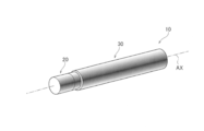
- FIG. 1 is a schematic perspective view of a flavor suction device according to the first embodiment.
- FIG. 2 is a cross-sectional view along the axial direction of the flavor suction device according to the first embodiment.
- FIG. 3 is a diagram illustrating a schematic configuration of a test sample of a carbon heat source according to an example of the first embodiment.
- FIG. 4 is a diagram illustrating a schematic configuration of a smoker and a carbon heat source according to an example of the first embodiment.
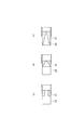
- FIG. 5 is a cross-sectional view along the axial direction of the carbon heat source according to the modified example of the first embodiment.
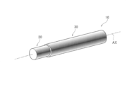
- FIG. 6 is a schematic perspective view of a flavor suction device according to the second embodiment.
- FIG. 1 is a schematic perspective view of a flavor suction device according to the first embodiment.
- FIG. 2 is a cross-sectional view along the axial direction of the flavor suction device according to the first embodiment.
- FIG. 3 is a diagram illustrating a schematic configuration of a test sample of
- FIG. 7 is a cross-sectional view along the axial direction of the flavor suction device according to the second embodiment.
- FIG. 8 is a cross-sectional view along the axial direction of the carbon heat source according to the modified example of the second embodiment.
- FIG. 9 is a schematic perspective view of a flavor suction device according to the third embodiment.
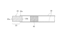
- FIG. 10 is sectional drawing along the axial direction of the flavor suction tool which concerns on 3rd Embodiment.
- FIG. 1 is an overall schematic configuration diagram of a flavor suction tool 10 according to the first embodiment.
- FIG. 2 is a cross-sectional view along the axial direction of the flavor suction tool 10.
- the flavor suction device 10 has an elongated cylindrical shape, and includes a carbon heat source 20, a holder 30, and a flavor generation source 40.
- the flavor suction tool 10 heats the flavor generating source 40 with heat generated from the carbon heat source 20 in order to suppress the generation of aerosol.
- the carbon heat source 20 is provided at the end 30e (one end) in the axis AX direction of the holder 30.
- the carbon heat source 20 is held by the end 30 e of the holder 30.
- the carbon heat source 20 includes a first portion 21 and a second portion 22. Specifically, the first portion 21 is held by the end 30 e of the holder 30.
- the first portion 21 is a portion that is held by the holder 30 and at least a portion of the first portion 21 protrudes from the holder 30 in the direction of the axis AX.
- the second portion 22 is a portion including an end portion on the opposite side to the flavor generation source 40.
- the second portion 22 is a portion that is adjacent to the first portion 21 and protrudes from the holder 30.
- At least the first portion 21 includes a fire spread inhibitor that prevents the carbon heat source 20 from spreading. This prevents the holder 30 from spreading due to the heat generated by the carbon heat source 20. A more specific configuration of the carbon heat source 20 will be described later.
- the holder 30 has a cylindrical shape containing the flavor generation source 40.
- the holder 30 can be configured by a paper tube formed as a hollow cylindrical body by curving a rectangular cardboard into a cylindrical shape and aligning both side edges.
- positions so that the carbon heat source 20 and the flavor generation source 40 may not adjoin by arrange
- the flavor generating source 40 generates flavor by being heated by the carbon heat source 20.
- tobacco leaf can be used.
- tobacco raw materials such as general cigarettes used for cigarettes (cigarettes), granular tobacco used for snuff tobacco, roll tobacco, and molded tobacco are used.
- Roll tobacco is obtained by forming sheet-like recycled tobacco into a roll shape, and has a flow path inside.
- molded tobacco is obtained by molding granular tobacco.
- a flavor component such as menthol may be supported on a porous or non-porous support.
- the carbon heat source 20 is adjacent to the holder 30 in the direction of the axis AX, and is adjacent to the first portion 21 that is provided so as to protrude at least partially from the holder 30, and And a second portion 22 provided so as to protrude from the holder 30.
- the first portion 21 and the second portion 22 are integrally formed.
- the carbon heat source 20 is obtained by molding a mixture containing a plant-derived carbonaceous material, an incombustible additive, an organic or inorganic binder and water by a method such as extrusion.
- the total length of the carbon heat source 20 is preferably in the range of 10 mm to 30 mm, and preferably in the range of 13 mm to 20 mm.
- the outer diameter of the carbon heat source 20 is preferably in the range of 4 mm to 8 mm, and preferably in the range of 5 mm to 7 mm. Thereby, it can be used suitably as a heat source of the flavor suction tool 10.
- the length of the carbon heat source 20 protruding from the holder 30 is preferably 8 mm to 15 mm.
- the length of the first portion 21 can be, for example, in the range of 1 mm to 5 mm, preferably in the range of 1.5 to 3 mm, in the portion protruding from the holder 30.
- the portion of the first portion 21 held by the holder 30 can be in the range of 3 mm to 10 mm, for example.
- the length of the second portion 22 can be set in the range of 8 mm to 10 mm, for example. With such a configuration, when the flavor suction tool 10 is used, the user can suck the flavor a sufficient number of times.
- the first portion 21 includes a fire spread inhibitor that prevents the carbon heat source 20 from spreading. That is, by including the fire spreader in the connection portion of the carbon heat source 20 with the holder 30, even if the user does not consciously extinguish the carbon heat source 20, the containing part containing the fire spreader is autonomous. Since the combustion is stopped, the spread of fire to the holder 30 or the like can be prevented.
- the characteristics of the fire spread inhibitor contained in the first portion 21 of the carbon heat source 20 will be described. It is preferable that the fire spread inhibitor contained in the first portion 21 is nonflammable at the combustion temperature of the carbon heat source 20 and causes an endothermic reaction below the combustion temperature of the carbon heat source 20. Further, when thermal decomposition occurs as an endothermic reaction, it is preferable that at least one of the thermal decomposition products is nonflammable and non-volatile at the combustion temperature of the carbon heat source 20.
- an inorganic substance that satisfies the following conditions can be used as the fire spread inhibitor.
- the inorganic substance can be added to the carbon heat source by a method such as a solution, suspension, paste, or granular material.
- a soluble or hardly soluble alkali metal salt that satisfies the above-mentioned conditions, or a soluble or hardly soluble alkaline earth metal salt can be preferably used.
- a soluble inorganic salt or a hardly soluble inorganic salt can be used as a fire spread inhibitor.
- Soluble inorganic salts include chlorides, carbonates or sulfates.
- Examples of the hardly soluble inorganic salt include hydroxide, carbonate or sulfate.
- chlorides such as sodium chloride, calcium chloride, magnesium chloride and potassium chloride, carbonates such as sodium carbonate and sodium bicarbonate, or sulfates such as sodium sulfate and magnesium sulfate and hydration thereof.
- materials particularly preferred are materials.
- hydroxides such as magnesium hydroxide and calcium hydroxide, carbonates such as calcium carbonate and magnesium carbonate, sulfates such as calcium sulfate and hydrates thereof are particularly preferable.
- inorganic salts as shown in Table 1 can be used as a fire spread inhibitor.
- a substance such as liquid glass can be used as a fire spread inhibitor.
- Such liquid glass can be obtained as a liquid coating agent at room temperature by the method disclosed in Japanese Patent No. 2538527, for example, and after adding the coating agent to the first portion 21 of the carbon heat source 20 by a method such as coating, By drying at room temperature to about 200 ° C., a film containing at least one of silicon or metal oxide can be formed.
- the first part 21 containing the fire spreader is added to a part of the carbon heat source 20 by a method such as dipping, spraying, spraying, wetting, or coating a solution, suspension, paste, or granular material of the fire spreader. Can be produced.
- one end of a carbon heat source 20 produced to a size suitable for the flavor suction device 10 is impregnated to a predetermined depth in a liquid in which a fire spreader is dissolved or dispersed, held for a certain time, and then dried.
- the first portion 21 can be provided over an arbitrary length.
- the content of the fire spread inhibitor in the first portion 21 can be arbitrarily controlled by the solution concentration of the fire spread inhibitor and the impregnation time.
- the carbon heat source 20 has an opening that communicates in the axis AX direction, such as a cylindrical shape, the impregnation position of the fire spread inhibitor is more accurately obtained by impregnating the solution with the fire spread inhibitor while venting the opening. Can be controlled.
- the content of the suitable fire spread inhibitor and the length of the processed portion in the first portion 21 are as follows. A value that provides a sufficient fire spread prevention effect is selected. Further, when the fire spread inhibitor is soluble, a higher fire spread preventing effect can be obtained by penetrating into the carbon heat source 20.
- the second portion 22 of the carbon heat source 20 may further include at least one of the inorganic substances listed in Table 1.
- the content of the inorganic substance contained in the second portion 22 with respect to the carbon heat source 20 is preferably smaller than the content of the fire spreader contained in the first portion 21 with respect to the carbon heat source 20.
- the carbon heat source 20 is not burned at the time of combustion due to an impact such as hitting an ashtray. Therefore, it is possible to prevent the carbon heat source 20 including the combustion part from dropping off (fire type dropping). Such an effect is particularly remarkable when an organic binder having a low thermal decomposition temperature is adopted as the binder of the carbon heat source 20.
- the content of the soluble alkali metal salt or alkaline earth metal salt contained in the first portion 21 is preferably smaller than the content of the fire spreader contained in the second portion 22. Furthermore, a portion other than the first portion 21 of the carbon heat source 20 may contain a low-concentration soluble alkali metal salt.
- Incombustibility at the combustion temperature of the carbon heat source 800 ° C. to 1200 ° C.
- At least one thermal decomposition product generated below the combustion temperature of the inorganic substance or the carbon heat source melts below the combustion temperature of the carbon heat source.
- the soluble alkali metal salts and alkaline earth metal salts listed in Table 1 can be suitably used.
- a low-concentration soluble alkali metal salt can be added in the form of a solid or liquid when a carbonaceous material or a binder is mixed during molding such as extrusion.
- the soluble alkali metal salt concentration of the second portion 22 excluding the first portion 21 is selected to be a value that provides a sufficient effect within a range that does not impair ignitability and other combustion characteristics. When selected, the concentration is preferably 5 wt% or less, and more preferably 0.5 wt% or less.
- Carbonaceous material It is desirable to use a carbonaceous material from which volatile impurities have been removed by heat treatment or the like, but is not limited thereto.
- the carbonaceous material can be included in the range of 10 wt% to 99 wt%, preferably 30 wt% to 70 wt%, and 40 wt% to 50 wt% to provide sufficient heat supply and combustion for preventing ash scattering, etc. Desirable from the viewpoint of characteristics.
- Binder As the binder, organic binders such as sodium carboxymethyl cellulose (CMC) and ammonium alginate, minerals such as purified bentonite, or silica binders such as colloidal silica, water glass and calcium silicate are used. Binders known to those skilled in the art, such as inorganic binders, can be used.
- the carbon heat source 20 includes the soluble alkali metal salt or the soluble alkaline earth metal salt listed in Table 1 and CMC is used as a binder
- the degree of etherification of CMC is set to 0.3 or more.
- the carbon heat source 20 can be given strength that can withstand manufacturing and use.
- CMC having a low degree of etherification is used, the strength after molding and drying is poor, and the suitability for production and use may be significantly deteriorated.
- CMC having a degree of etherification of less than 0.8 it becomes possible to easily mold at the time of molding such as extrusion.
- CMC can be contained in an amount of 1 to 10 wt%, and more preferably 1 wt% to 8 wt% from the viewpoint of flavor.
- Nonflammable additive for example, a carbonate or oxide composed of sodium, potassium, calcium, magnesium, silicon, etc. can be used, and it can be contained in 40 to 89 wt%. In particular, it is preferable to contain 40 wt% to 55 wt% of calcium carbonate in the carbon heat source 20.
- a carbon heat source 20 having the composition shown in Table 2 was produced by the following method. -86 g of activated carbon and 117 g of calcium carbonate (CaCO 3 ) are mixed with 10.8 g of CMC having a degree of etherification of 0.6, and 250 g of water containing 2.2 g of sodium chloride is further mixed. Extrusion molding so as to form a cylindrical shape of 6 mm and an inner diameter of 4 mm. After the molding is dried, it is cut into a length of 13 mm to obtain the carbon heat source 20.
- -86 g of activated carbon and 117 g of calcium carbonate (CaCO 3 ) are mixed with 10.8 g of CMC having a degree of etherification of 0.6, and 250 g of water containing 2.2 g of sodium chloride is further mixed. Extrusion molding so as to form a cylindrical shape of 6 mm and an inner diameter of 4 mm. After the molding is dried, it is cut into a length of 13 mm to obtain the carbon heat source 20
- test Sample The carbon heat source produced by the above-described method was impregnated with an aqueous NaCl solution to produce test heat sources A to F shown in Table 3.
- test heat sources A to F were impregnated with NaCl by the following method. ⁇ Insert a 13 mm heat source into a tube with an inner diameter of 5 mm, and immerse each sample in a NaCl aqueous solution having a concentration shown in Table 3 for 210 seconds while flowing air at 1000 ml / min. Dry at 6 ° C. for 6 hours to obtain a NaCl impregnation heat source
- the weight ratio of NaCl and combustible material (sum of carbonaceous material and organic binder) is 0.35 or more, or the weight ratio of NaCl and carbonaceous material is 0.40 or more in the impregnation part of the fire spreader.
- the content of the fire spread inhibitor in the carbon heat source 20 in the impregnated portion of the suspension or liquid glass of CaCO 3 or Mg (OH) 2 was calculated by the following equation.
- ⁇ 1mm present fire spreader content addition amount of fire spread inhibitor / length of impregnated part in heat source
- any of the fire spread inhibitors (CaCO 3 , Mg (OH) 2 , liquid glass) used in this test contains a predetermined amount in the carbon heat source 20, so that the content of the fire spread inhibitor is included. It was confirmed that combustion can be stopped autonomously at
- ⁇ The amount of addition required to stop combustion differs depending on the type of fire spread inhibitor used. For example, Mg (OH) 2 is considered to have a higher combustion stop effect than CaCO 3 . It is presumed that Mg (OH) 2 has a larger endothermic amount in pyrolysis. ⁇ The effect of preventing fire spread differs depending on the ratio of the amount added to the inside of the hole and the outer periphery.
- test sample A test sample of a carbon heat source 20 (total length 15 mm, outer diameter 6 mm) having the composition shown in Table 8 was produced by extrusion molding.
- excessive heat supply to the holder 30 can be prevented without providing another member other than the carbon heat source 20, and combustion or thermal decomposition of the holder 30 can be prevented. That is, since supply of excessive heat to the holder 30 is prevented, it is not necessary to give the holder 30 special heat resistance, and even a material such as a paper tube can be suitably used as the holder 30 and the manufacturing cost is increased. Can be suppressed.
- the shapes of the first portion 21 and the second portion 22 of the carbon heat source 20 may be changed as follows.
- 5A to 5C are cross-sectional views along the axial direction of the carbon heat source according to the modified example of the present invention.
- the fire spread inhibitor (dot portion in the figure) may be disposed on the outer peripheral portion of the first portion 21. Further, as shown in FIG. 5B, the first portion 21 spreads as it approaches the flavor generating source 40 (not shown in FIG. 5B) in the cross section along the axial direction of the holder 30. You may comprise so that the area
- the portion of the first portion 21 that does not contain the fire spread inhibitor is substantially triangular, but the portion does not necessarily have a triangular shape, and may be a pyramid shape, for example.
- both the first portion 21 and the second portion 22 are provided with a fire spread inhibitor as they approach the flavor generating source 40 in the cross section along the axial direction of the holder 30. You may comprise so that the area
- the fire spreader is included in the entire axis AX of the first portion 21 .
- the fire spreader may be included only in the first portion 21 that is not held by the holder 30.
- the flame spreader containing region is variously changed in the carbon heat source 20
- the substance may be contained at different concentrations in the axial direction of the carbon heat source 20.
- An example of the configuration described in (1-5.1) is that the second portion 22 contains a low concentration of soluble alkali metal salt or soluble alkaline earth metal salt.
- the concentration gradient can be realized such that the concentration of the substance is thin on the ignition end side of the carbon heat source 20 and the holder 30 side is thick. Thereby, the amount of heat generated by the carbon heat source 20 can be controlled more precisely.
- the preferable content (concentration) of the fire spread inhibitor varies depending on the shape and composition (calorific value) of the carbon heat source 20 as well as the type of the fire spread inhibitor, but it depends on the method shown in (1-4).
- the fire spread inhibitor can be set to an arbitrary content.
- the outer shape of the carbon heat source 20 is a cylindrical shape.
- the present invention is not limited to the cylindrical shape, and various shapes such as a rectangular parallelepiped are naturally included in the present invention.
- FIG. 6 is an overall schematic configuration diagram of the flavor suction tool 10 according to the second embodiment.
- FIG. 7 is a cross-sectional view of the flavor suction tool 10 along the axial direction.
- the flavor inhaler 10 has an elongated cylindrical shape as in the first embodiment, and includes a carbon heat source 20, a holder 30, and a flavor generation source 40.
- the flavor suction tool 10 heats the flavor generating source 40 with heat generated from the carbon heat source 20 in order to suppress the generation of aerosol.
- the carbon heat source 20 is adjacent to the holder 30 in the axis AX direction, and is adjacent to the first portion 21 and the first portion 21 provided so as to protrude at least partially from the holder 30. And a second portion 22 provided so as to protrude from the holder 30.
- the first portion 21 and the second portion 22 are integrally formed.
- the second portion 22 can also contain a low concentration of NaCl (an example of a fire spread inhibitor). That is, the content rate of NaCl in the second part 22 with respect to the carbon heat source 20 is smaller than the content rate of NaCl in the first part 21 with respect to the carbon heat source 20.
- the carbon heat source 20 can be produced even if the holder 30 is spread by the heat generated by the carbon heat source 20 without impeding the ignitability of the carbon heat source 20 and the flavor suction tool 10 is hit against an ashtray with a certain level of force. Can prevent the burning part (fire type) from falling. Such an effect is particularly remarkable when an organic binder having a low thermal decomposition temperature is adopted as the binder of the carbon heat source 20.
- the first portion 21 containing high-concentration NaCl is added to a part of the carbon heat source 20 by immersing, spraying, spraying, wetting, coating, or the like a solution, suspension, paste, or powder of NaCl. Can be produced.
- the first portion 21 can be provided over any length.
- the NaCl content in the first portion 21 can be arbitrarily controlled by the NaCl solution concentration and the impregnation time.
- the carbon heat source 20 has an opening communicating in the direction of the axis AX like a cylindrical shape, the NaCl impregnation position can be controlled with higher accuracy by impregnating with the NaCl solution while venting the opening.
- a suitable NaCl content in the first portion 21 and the length of the processed portion are values that can obtain a sufficient fire spread prevention effect in consideration of the relationship with the characteristics (shape, composition, etc.) of the carbon heat source 20 to be processed. Is selected. Further, by infiltrating NaCl into the carbon heat source 20, a higher fire spread prevention effect can be obtained.
- the carbon heat source 20 can be provided with a fire type (carbon heat source 20) fall prevention function by low concentration sodium chloride (NaCl).
- NaCl sodium chloride
- Such low-concentration NaCl can be added in the form of a solid or liquid when, for example, a carbonaceous material or a binder is mixed during molding such as extrusion.
- the NaCl concentration of the second portion 22 excluding the first portion 21 is selected to be a value that provides a sufficient effect within a range that does not impair the ignitability and other combustion characteristics, but may be, for example, 1 wt% or less. Preferably, it is 0.5 wt% or less.
- Carbonaceous material It is desirable to use a carbonaceous material from which volatile impurities have been removed by heat treatment or the like, but is not limited thereto.
- the carbonaceous material can be included in the range of 10 wt% to 99 wt%, preferably 30 wt% to 70 wt%, and 40 wt% to 50 wt% to provide sufficient heat supply and combustion for preventing ash scattering, etc. Desirable from the viewpoint of characteristics.
- the carbonaceous material is not limited to this.
- the carbonaceous material can be included in the range of 10 wt% to 99 wt%, preferably 30 wt% to 70 wt%, and 40 wt% to 50 wt% to provide sufficient heat supply and combustion for preventing ash scattering, etc. Desirable from the viewpoint of characteristics.
- Binder As the binder, organic binders such as sodium carboxymethylcellulose (CMC) and ammonium alginate, minerals such as purified bentonite, or silica binders such as colloidal silica, water glass and calcium silicate are used. Binders known to those skilled in the art, such as inorganic binders, can be used.
- CMC carboxymethylcellulose
- ammonium alginate minerals such as purified bentonite
- silica binders such as colloidal silica, water glass and calcium silicate are used. Binders known to those skilled in the art, such as inorganic binders, can be used.
- the degree of etherification of CMC is set to 0.3 or more.
- the carbon heat source 20 can be given strength that can withstand manufacturing and use.
- CMC having a low degree of etherification is used, the strength after molding and drying is poor, and the suitability for production and use may be significantly deteriorated.
- CMC having a degree of etherification of less than 0.8 it becomes possible to easily mold at the time of molding such as extrusion.
- CMC can be contained in an amount of 1 to 10 wt%, and more preferably 1 wt% to 8 wt% from the viewpoint of flavor.
- Nonflammable additives for example, carbonates or oxides composed of sodium, potassium, calcium, magnesium, silicon and the like can be used, and they can be contained in 40 to 89 wt%. In particular, it is preferable to contain 40 wt% to 55 wt% of calcium carbonate in the carbon heat source 20.
- Carbon heat source 20 having the composition shown in Table 9 is produced by the following method. did. -86 g of activated carbon and 117 g of calcium carbonate (CaCO 3 ) are mixed with 10.8 g of CMC having a degree of etherification of 0.6, and 250 g of water containing 2.2 g of sodium chloride is further mixed. Extrusion molding so as to form a cylindrical shape of 6 mm and an inner diameter of 4 mm. After the molding is dried, it is cut into a length of 13 mm to obtain the carbon heat source 20.
- Test Sample Test heat sources A to F shown in Table 10 were produced by impregnating the carbon heat source produced by the above-described method with an aqueous NaCl solution.
- test heat sources A to F were impregnated with NaCl by the following method. Insert a 10 mm heat source into a tube with an inner diameter of 5 mm and immerse each sample in a NaCl aqueous solution having the concentration shown in Table 11 for 210 seconds while flowing air at 1000 ml / min. Dry at 6 ° C. for 6 hours to obtain a NaCl impregnation heat source
- the weight ratio of NaCl to combustible material is 0.35 or more, or NaCl to carbonaceous material.
- the carbon heat source 20 contains at least a portion of NaCl, and the content of NaCl in the first portion 21 with respect to the carbon heat source 20 is the same as the carbon of NaCl in the second portion 22. It is larger than the content rate with respect to the heat source 20. For this reason, it is possible to prevent the combustion of the carbon heat source 20 from proceeding to the contact portion with the holder 30 containing the flavor generating source 40 due to the effect of preventing the spread of NaCl in the first portion 21. Further, according to the second embodiment, it is possible to realize a concentration gradient such that the concentration of the substance is low on the ignition end side of the carbon heat source 20 and the holder 30 side is high. Thereby, the amount of heat generated by the carbon heat source 20 can be controlled more precisely.
- NaCl is effective in preventing the carbon heat source 20 from falling off. Moreover, it is not necessary to provide another member other than the carbon heat source 20 as described above, and an increase in manufacturing cost can be suppressed.
- the weight ratio of NaCl and combustible in the first part is 0.35 or more, and the weight ratio of NaCl and carbonaceous material in the first part is 0.40 or more. In this case, a further sufficient fire spread preventing effect can be obtained.
- FIGS. 8A to 8C are cross-sectional views along the axial direction of the carbon heat source according to the modified example of the present invention.
- NaCl (dot portion in the figure) may be arranged on the outer peripheral portion of the first portion 21.
- the first portion 21 is NaCl in the cross section along the axial direction of the holder 30 as it approaches the flavor generating source 40 (not shown in FIG. 8B).
- the region including (dot portion in the figure) may be widened.
- the portion of the first portion 21 that does not contain NaCl has a substantially triangular shape, but the portion does not necessarily have a triangular shape, and may have a pyramid shape, for example.
- both the first portion 21 and the second portion 22 are regions containing NaCl as they approach the flavor generating source 40 in the cross section along the axial direction of the holder 30. May be configured to be wide.
- the example in which NaCl is included in the entire axis AX of the first portion 21 has been described. However, it is sufficient that at least a portion of the first portion 21 includes NaCl. Only the first portion 21 that is not held by may be made to contain NaCl.
- NaCl-containing region is variously changed in the carbon heat source 20
- NaCl may be contained in different concentrations in the axial direction of the carbon heat source 20.
- the configuration described in (2-2) including low concentration NaCl in the second portion 22 is an example.
- the concentration gradient can be realized so that the NaCl concentration is low on the ignition end side of the carbon heat source 20 and the holder 30 side is high. Thereby, the amount of heat generated by the carbon heat source 20 can be controlled more precisely.
- the preferred NaCl content varies depending on the shape and composition (calorific value) of the carbon heat source 20, but by the method shown in (2-3) or (2-4), the effect of preventing the spread of fire or NaCl can be set to an arbitrary content so that the effect of preventing the drop of fire can be achieved.
- the outer shape of the carbon heat source 20 is cylindrical.
- the present invention is not limited to the cylindrical shape, and various shapes such as a rectangular parallelepiped are also included in the present invention.
- FIG. 9 is an overall schematic configuration diagram of the flavor suction tool 10 according to the third embodiment.
- FIG. 10 is a cross-sectional view along the axial direction of the flavor suction tool 10.
- the flavor suction tool 10 has an elongated cylindrical shape as in the first embodiment, and includes a carbon heat source 20, a holder 30, and a flavor generation source 40.
- the flavor suction tool 10 heats the flavor generating source 40 with the heat generated from the carbon heat source 20 without burning or pyrolyzing the flavor generating source 40.
- the carbon heat source 20 is provided at the end 30e (one end) in the axis AX direction of the holder 30.
- the carbon heat source 20 is held by the end 30 e of the holder 30.
- the carbon heat source 20 has a protruding portion 23 at least partially protruding from the holder 30.
- the length of the protruding portion 23 can be 8 mm to 15 mm, for example. With such a configuration, the user can easily visually recognize the combustion state of the carbon heat source 20 during use. A more specific configuration of the carbon heat source 20 will be described later.
- the carbon heat source 20 is obtained by molding a mixture containing a plant-derived carbonaceous material, an incombustible additive, an organic binder and water by a method such as extrusion.
- the carbon heat source 20 includes a carbonaceous material, an organic binder, and a reinforcing agent.
- the organic binder it is particularly preferable to use sodium carboxymethylcellulose (CMC) from the viewpoint of flavor.
- CMC carboxymethylcellulose
- other organic binders for example, ammonium alginate, are used, there is a possibility that the thermal decomposition product generated with combustion of the carbon heat source 20 may inhibit the flavor.
- the degree of etherification of CMC is set to 0.3 or more. The degree of etherification is preferably less than 0.8.
- the reinforcing agent is nonflammable at the combustion temperature of the carbon heat source 20, and at least one thermal decomposition product generated below the combustion temperature of the carbon heat source 20 is melted below the combustion temperature of the carbon heat source 20.
- the reinforcing agent is nonflammable at 800 ° C. to 1200 ° C., which is the combustion temperature of the carbon heat source 20, and at least one pyrolyzate generated below the combustion temperature of the carbon heat source 20 is carbon dioxide. It has a characteristic of melting at a temperature lower than the combustion temperature of the heat source 20.
- the reinforcing agent is preferably made of at least one of a soluble alkali metal salt or a soluble alkaline earth metal salt that satisfies the above-mentioned conditions.
- a soluble alkali metal salt or a soluble alkaline earth metal salt include chlorides, carbonates, and sulfates.
- sodium chloride, calcium chloride, magnesium chloride, potassium chloride, sodium carbonate, sodium hydrogen carbonate, sodium sulfate, magnesium sulfate can be mentioned, and sodium chloride (NaCl) can be preferably used.
- NaCl sodium chloride
- it is preferable that the content rate of NaCl is 5 wt% or less with respect to the weight of the carbon heat source 20.
- the carbon heat source 20 breaks from the non-combustion portion due to an impact such as a hit to the ashtray during the combustion of the carbon heat source 20, and includes the combustion portion. It is possible to prevent a part of the carbon heat source 20 from dropping (fire type dropping).
- the value of the reinforcing agent concentration of the carbon heat source 20 is selected so as to obtain a sufficient effect within a range that does not impair ignitability and other combustion characteristics.
- NaCl specifically, it is sufficient that NaCl is contained in the carbon heat source 20 to some extent.
- the mass percent concentration (NaCl concentration) of NaCl with respect to the carbon heat source 20 is 5 wt% or less, and can be employed without impairing the ignitability.
- NaCl can be added as a granule or a solution when mixing a carbonaceous material, a binder, or the like during molding such as extrusion.
- the degree of etherification of CMC is set to 0.3 or more. By doing in this way, even when the carbon heat source 20 contains a reinforcing agent, the carbon heat source 20 can be provided with strength that can withstand manufacturing and use.
- CMC having a low degree of etherification When CMC having a low degree of etherification is used, the strength after molding and drying is poor, and the suitability for production and use may be significantly deteriorated. Further, for example, by using CMC having a degree of etherification of less than 0.8, it becomes possible to easily mold at the time of molding such as extrusion.
- CMC can be contained in an amount of 1 to 10 wt%, and more preferably 1 wt% to 8 wt% from the viewpoint of flavor.
- the carbon heat source 20 may have different reinforcing agent concentrations in the direction of the axis AX.
- the content of the reinforcing agent with respect to the carbon heat source 20 on the other end 20b side of the carbon heat source 20 may be larger than the content of the reinforcing agent on the one end 20a side of the carbon heat source 20, more specifically.
- a part of the carbon heat source 20, specifically, near the other end 20 b contains a soluble alkali metal salt or alkaline earth metal salt having a higher concentration than the portion including the one end 20 a (protruding portion). Also good.
- the combustion of the carbon heat source 20 is stopped autonomously in the containing portion, and the carbon heat source 20 is transferred to the holder. Fire spread can be prevented more reliably.
- the holder 30 is exposed by exposing at least a part of the portion (second portion) of the carbon heat source 20 containing the high-concentration soluble alkali metal salt or alkaline earth metal salt as described above.
- the combustion of the carbon heat source 20 can be stopped before excessive heat is supplied to 30 or the like.
- the length of the portion of the carbon heat source 20 containing a high concentration of soluble alkali metal salt or alkaline earth metal salt to be exposed from the holder 30 is 1 mm to 5 mm, more preferably 1.5 mm to 3 mm.
- the soluble alkali metal salt or alkaline earth metal salt concentration to be contained on the other end portion 20b side of the carbon heat source 20 is sufficiently spread from the relationship with the carbonaceous material blending ratio in the carbon heat source 20 and the air flow path structure.
- a numerical value that achieves the prevention function is appropriately selected. For example, when NaCl is used, NaCl is added so that the weight ratio of NaCl to combustible material (sum of carbonaceous material and organic binder) is 0.35 or more, or the weight ratio of NaCl to carbonaceous material is 0.40 or more.
- the portion of the carbon heat source 20 containing a high concentration of soluble alkali metal salt or alkaline earth metal salt is obtained by, for example, replacing one end portion of the carbon heat source 20 having a size suitable for the flavor suction tool 10 with a soluble alkali. It can be formed by impregnating an aqueous solution containing a metal salt or an alkaline earth metal salt to a predetermined depth, holding it for a certain time, and then drying.
- the content of the soluble alkali metal salt or alkaline earth metal salt in the other end portion 20b of the carbon heat source 20 can be arbitrarily controlled by the concentration of the soluble alkali metal salt or alkaline earth metal salt solution and the impregnation time. For example, when NaCl is used, the concentration of the NaCl aqueous solution used for impregnation is preferably 15 wt% to 26 wt%.
- the carbon heat source 20 has an opening that communicates in the axis AX direction like a cylindrical shape, a soluble alkali metal salt or an alkaline earth metal salt is impregnated with an aqueous solution while passing through the opening.
- the impregnation position of the alkali metal salt or alkaline earth metal salt can be controlled more accurately.
- Carbonaceous material It is desirable to use a carbonaceous material from which volatile impurities have been removed by heat treatment or the like, but is not limited thereto.
- the carbonaceous material can be included in the range of 10 wt% to 99 wt%, preferably 30 wt% to 70 wt%, and 40 wt% to 50 wt% to provide sufficient heat supply and combustion for preventing ash scattering, etc. Desirable from the viewpoint of characteristics.
- nonflammable additives for example, carbonates or oxides composed of sodium, potassium, calcium, magnesium, silicon and the like can be used, and they can be contained in 40 to 89 wt%. In particular, it is preferable to contain 40 wt% to 55 wt% of calcium carbonate in the carbon heat source 20.
- the total length of the carbon heat source 20 is preferably in the range of 10 mm to 30 mm, and more preferably in the range of 13 mm to 20 mm. Further, the outer diameter of the carbon heat source 20 is preferably in the range of 4 mm to 8 mm, and more preferably in the range of 5 mm to 7 mm. Thereby, it can be used suitably as a heat source of the flavor suction tool 10.
- the carbon heat source 20 has the protruding portion 23 protruding from the holder 30. For this reason, the user can visually recognize the combustion state of the carbon heat source 20 easily.
- the carbon heat source 20 contains a reinforcing agent and sodium carboxymethyl cellulose (CMC), and the degree of etherification of CMC is 0.3 or more. For this reason, even if the flavor suction tool 10 is struck against an ashtray or the like with a certain force or more while giving the carbon heat source 20 strength sufficient to withstand manufacture and use, the combustion part (fire type) can be prevented from falling.
- CMC sodium carboxymethyl cellulose
- the binder contained in the carbon heat source 20 is desirably CMC from the viewpoint of flavor, but in the production of a carbon heat source containing a reinforcing agent, when CMC having a degree of etherification of less than 0.3 is used, The strength after molding and drying is poor, and the suitability for production and use may be significantly deteriorated. That is, the inventor of the present application ensures the strength of the carbon heat source 20 that can withstand production and use by including NaCl and CMC in the carbon heat source 20 and setting the degree of etherification of CMC to 0.3 or more. In addition, they have acquired knowledge that fire omission can be effectively prevented.
- the degree of etherification of CMC in the range of 0.3 to 0.8, it is possible to achieve both the guarantee of strength when the carbon heat source 20 is not burned and the ease of molding. Furthermore, in the direction of the axis AX of the flavor suction tool 10, the effect of preventing the spread of fire to the holder of the carbon heat source 20 is also achieved by imparting a concentration gradient to the reinforcing agent, particularly a soluble alkali metal salt or a soluble alkaline earth metal salt. Can do.
- reinforcing agent density concentration different in the axis line AX direction of the carbon heat source 20, for example, in a part of carbon heat source 20, specifically, the other end part 20b side (2nd part).
- concentration different in the axis line AX direction of the carbon heat source 20 for example, in a part of carbon heat source 20, specifically, the other end part 20b side (2nd part).
- a higher concentration of reinforcing agent may be contained than the portion including the one end portion 20a (protruding portion), such a configuration is not essential for achieving the above-described effects of the present invention.
- the supply of excessive heat to the holder is suppressed and the combustion or pyrolysis of the holder is prevented without providing another member other than the carbon heat source in the portion of the carbon heat source held by the holder. And a carbon heat source.
Landscapes
- Manufacture Of Tobacco Products (AREA)
Abstract
Cette invention concerne un outil d'inhalation de parfum (10) comprenant : un support cylindrique (30) qui renferme une source générant un parfum (40) ; et une source de chaleur au carbone (20) qui se trouve à une partie d'extrémité du support (30) dans son sens axial (AX). La source de chaleur au carbone (20) est maintenue par le support ((30) dans son sens axial (AX), et comporte une première section (21), qui fait au moins en partie saillie par rapport au support (30), et une seconde section (22) qui se trouve à la partie d'extrémité du côté opposé à la source génératrice de parfum (40). Une partie au moins de la première section (21) contient un retardateur d'inflammation qui empêche la propagation du feu à partir de la source de chaleur au carbone (20).
Priority Applications (1)
| Application Number | Priority Date | Filing Date | Title |
|---|---|---|---|
| JP2014512728A JP5816360B2 (ja) | 2012-04-27 | 2013-04-26 | 香味吸引具及び炭素熱源 |
Applications Claiming Priority (6)
| Application Number | Priority Date | Filing Date | Title |
|---|---|---|---|
| JP2012-104148 | 2012-04-27 | ||
| JP2012104143 | 2012-04-27 | ||
| JP2012104148 | 2012-04-27 | ||
| JP2012-104143 | 2012-04-27 | ||
| JP2012-106201 | 2012-05-07 | ||
| JP2012106201 | 2012-05-07 |
Publications (1)
| Publication Number | Publication Date |
|---|---|
| WO2013162028A1 true WO2013162028A1 (fr) | 2013-10-31 |
Family
ID=49483323
Family Applications (1)
| Application Number | Title | Priority Date | Filing Date |
|---|---|---|---|
| PCT/JP2013/062491 WO2013162028A1 (fr) | 2012-04-27 | 2013-04-26 | Outil d'inhalation de parfum et source de chaleur au carbone |
Country Status (3)
| Country | Link |
|---|---|
| JP (1) | JP5816360B2 (fr) |
| TW (1) | TW201400040A (fr) |
| WO (1) | WO2013162028A1 (fr) |
Cited By (7)
| Publication number | Priority date | Publication date | Assignee | Title |
|---|---|---|---|---|
| WO2016156424A1 (fr) * | 2015-03-31 | 2016-10-06 | Philip Morris Products S.A. | Article à fumer avec moyen de préhension de source thermique combustible |
| WO2017040608A2 (fr) | 2015-08-31 | 2017-03-09 | R. J. Reynolds Tobacco Company | Article pour fumeurs |
| WO2017098464A1 (fr) | 2015-12-10 | 2017-06-15 | R. J. Reynolds Tobacco Company | Article à fumer |
| CN111165906A (zh) * | 2020-01-22 | 2020-05-19 | 同济大学 | 一种空气预热型加热不燃烧卷烟及工作方法 |
| US11096413B2 (en) | 2015-09-11 | 2021-08-24 | Philip Morris Products S.A. | Multi-segment component for an aerosol-generating article |
| US11375745B2 (en) | 2013-09-25 | 2022-07-05 | R.J. Reynolds Tobacco Company | Heat generation apparatus for an aerosol-generation system of a smoking article, and associated smoking article |
| US11744296B2 (en) | 2015-12-10 | 2023-09-05 | R. J. Reynolds Tobacco Company | Smoking article |
Citations (6)
| Publication number | Priority date | Publication date | Assignee | Title |
|---|---|---|---|---|
| JPH0286759A (ja) * | 1988-07-22 | 1990-03-27 | Philip Morris Prod Inc | 炭素熱源 |
| JPH04501523A (ja) * | 1988-11-01 | 1992-03-19 | カタリティカ,インコーポレイティド | 一酸化炭素の酸化の最適化 |
| JPH06189733A (ja) * | 1992-09-17 | 1994-07-12 | R J Reynolds Tobacco Co | シガレット及びその製造方法 |
| WO2007119678A1 (fr) * | 2006-04-11 | 2007-10-25 | Japan Tobacco Inc. | Formule de source de chaleur carbonée pour article non combustible destiné à être fumé et article non combustible destiné à être fumé |
| JP2010535530A (ja) * | 2007-08-10 | 2010-11-25 | フィリップ・モーリス・プロダクツ・ソシエテ・アノニム | 蒸留ベースの喫煙物品 |
| WO2011118043A1 (fr) * | 2010-03-26 | 2011-09-29 | 日本たばこ産業株式会社 | Elément combustible d'un article à fumer sans combustion et procédé de fabrication de ce dernier |
-
2013
- 2013-04-26 WO PCT/JP2013/062491 patent/WO2013162028A1/fr active Application Filing
- 2013-04-26 JP JP2014512728A patent/JP5816360B2/ja active Active
- 2013-04-29 TW TW102115222A patent/TW201400040A/zh unknown
Patent Citations (6)
| Publication number | Priority date | Publication date | Assignee | Title |
|---|---|---|---|---|
| JPH0286759A (ja) * | 1988-07-22 | 1990-03-27 | Philip Morris Prod Inc | 炭素熱源 |
| JPH04501523A (ja) * | 1988-11-01 | 1992-03-19 | カタリティカ,インコーポレイティド | 一酸化炭素の酸化の最適化 |
| JPH06189733A (ja) * | 1992-09-17 | 1994-07-12 | R J Reynolds Tobacco Co | シガレット及びその製造方法 |
| WO2007119678A1 (fr) * | 2006-04-11 | 2007-10-25 | Japan Tobacco Inc. | Formule de source de chaleur carbonée pour article non combustible destiné à être fumé et article non combustible destiné à être fumé |
| JP2010535530A (ja) * | 2007-08-10 | 2010-11-25 | フィリップ・モーリス・プロダクツ・ソシエテ・アノニム | 蒸留ベースの喫煙物品 |
| WO2011118043A1 (fr) * | 2010-03-26 | 2011-09-29 | 日本たばこ産業株式会社 | Elément combustible d'un article à fumer sans combustion et procédé de fabrication de ce dernier |
Cited By (14)
| Publication number | Priority date | Publication date | Assignee | Title |
|---|---|---|---|---|
| US11375745B2 (en) | 2013-09-25 | 2022-07-05 | R.J. Reynolds Tobacco Company | Heat generation apparatus for an aerosol-generation system of a smoking article, and associated smoking article |
| US12089628B2 (en) | 2013-09-25 | 2024-09-17 | R.J. Reynolds Tobacco Company | Heat generation apparatus for an aerosol-generation system of a smoking article, and associated smoking article |
| US11707083B2 (en) | 2013-09-25 | 2023-07-25 | R.J. Reynolds Tobacco Company | Heat generation apparatus for an aerosol-generation system of a smoking article, and associated smoking article |
| WO2016156424A1 (fr) * | 2015-03-31 | 2016-10-06 | Philip Morris Products S.A. | Article à fumer avec moyen de préhension de source thermique combustible |
| RU2692828C2 (ru) * | 2015-03-31 | 2019-06-28 | Филип Моррис Продактс С.А. | Курительное изделие со средством захвата горючего источника теплоты |
| US10631571B2 (en) | 2015-03-31 | 2020-04-28 | Philip Morris Products S.A. | Smoking article with combustible heat source gripping means |
| WO2017040608A2 (fr) | 2015-08-31 | 2017-03-09 | R. J. Reynolds Tobacco Company | Article pour fumeurs |
| EP4338630A2 (fr) | 2015-08-31 | 2024-03-20 | R. J. Reynolds Tobacco Company | Article à fumer |
| US11096413B2 (en) | 2015-09-11 | 2021-08-24 | Philip Morris Products S.A. | Multi-segment component for an aerosol-generating article |
| US10314334B2 (en) | 2015-12-10 | 2019-06-11 | R.J. Reynolds Tobacco Company | Smoking article |
| US10874140B2 (en) | 2015-12-10 | 2020-12-29 | R.J. Reynolds Tobacco Company | Smoking article |
| US11744296B2 (en) | 2015-12-10 | 2023-09-05 | R. J. Reynolds Tobacco Company | Smoking article |
| WO2017098464A1 (fr) | 2015-12-10 | 2017-06-15 | R. J. Reynolds Tobacco Company | Article à fumer |
| CN111165906A (zh) * | 2020-01-22 | 2020-05-19 | 同济大学 | 一种空气预热型加热不燃烧卷烟及工作方法 |
Also Published As
| Publication number | Publication date |
|---|---|
| TW201400040A (zh) | 2014-01-01 |
| JPWO2013162028A1 (ja) | 2015-12-24 |
| JP5816360B2 (ja) | 2015-11-18 |
Similar Documents
| Publication | Publication Date | Title |
|---|---|---|
| JP5816360B2 (ja) | 香味吸引具及び炭素熱源 | |
| JP7470658B2 (ja) | 喫煙用物品のエアゾール発生システム用の熱発生セグメント | |
| US10874140B2 (en) | Smoking article | |
| RU2739443C2 (ru) | Генерирующее аэрозоль изделие, имеющее новый табачный субстрат | |
| US10362802B2 (en) | Burning type heat source, flavor inhaler, and manufacturing method of burning type heat source | |
| PL201485B1 (pl) | Owijka artykułu do palenia, papieros i materiał warstwowy papierosa | |
| EP2974606B1 (fr) | Source de chaleur à combustion et inhalateur d'arôme | |
| US11744296B2 (en) | Smoking article | |
| EA030672B1 (ru) | Ингалятор аромата | |
| KR101765803B1 (ko) | 소화부가 형성된 화재 방지 담배 |
Legal Events
| Date | Code | Title | Description |
|---|---|---|---|
| 121 | Ep: the epo has been informed by wipo that ep was designated in this application |
Ref document number: 13780975 Country of ref document: EP Kind code of ref document: A1 |
|
| ENP | Entry into the national phase |
Ref document number: 2014512728 Country of ref document: JP Kind code of ref document: A |
|
| NENP | Non-entry into the national phase |
Ref country code: DE |
|
| 122 | Ep: pct application non-entry in european phase |
Ref document number: 13780975 Country of ref document: EP Kind code of ref document: A1 |