WO2013161817A1 - 走行区画線認識装置 - Google Patents
走行区画線認識装置 Download PDFInfo
- Publication number
- WO2013161817A1 WO2013161817A1 PCT/JP2013/061923 JP2013061923W WO2013161817A1 WO 2013161817 A1 WO2013161817 A1 WO 2013161817A1 JP 2013061923 W JP2013061923 W JP 2013061923W WO 2013161817 A1 WO2013161817 A1 WO 2013161817A1
- Authority
- WO
- WIPO (PCT)
- Prior art keywords
- blur
- vehicle
- road surface
- image
- lane marking
- Prior art date
- Legal status (The legal status is an assumption and is not a legal conclusion. Google has not performed a legal analysis and makes no representation as to the accuracy of the status listed.)
- Ceased
Links
Images
Classifications
-
- G—PHYSICS
- G06—COMPUTING OR CALCULATING; COUNTING
- G06T—IMAGE DATA PROCESSING OR GENERATION, IN GENERAL
- G06T11/00—2D [Two Dimensional] image generation
- G06T11/001—Texturing; Colouring; Generation of texture or colour
-
- G—PHYSICS
- G08—SIGNALLING
- G08G—TRAFFIC CONTROL SYSTEMS
- G08G1/00—Traffic control systems for road vehicles
- G08G1/16—Anti-collision systems
- G08G1/167—Driving aids for lane monitoring, lane changing, e.g. blind spot detection
-
- G—PHYSICS
- G06—COMPUTING OR CALCULATING; COUNTING
- G06T—IMAGE DATA PROCESSING OR GENERATION, IN GENERAL
- G06T11/00—2D [Two Dimensional] image generation
- G06T11/60—Editing figures and text; Combining figures or text
-
- G—PHYSICS
- G06—COMPUTING OR CALCULATING; COUNTING
- G06V—IMAGE OR VIDEO RECOGNITION OR UNDERSTANDING
- G06V20/00—Scenes; Scene-specific elements
- G06V20/50—Context or environment of the image
- G06V20/56—Context or environment of the image exterior to a vehicle by using sensors mounted on the vehicle
- G06V20/588—Recognition of the road, e.g. of lane markings; Recognition of the vehicle driving pattern in relation to the road
Definitions
- the present invention relates to a travel lane marking recognition device that recognizes a travel lane marking on a road surface.
- a traveling lane marking recognition device that recognizes a traveling lane marking on a road (for example, a white line) is known.
- the travel lane marking recognition apparatus acquires an image around the vehicle with an in-vehicle camera, and recognizes the travel lane marking from the image by a method of image recognition.
- the recognized lane markings can be used for driving support systems such as a lane departure warning system and a lane keeping assist system.
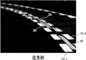
- One type of lane marking is an intermittent double line. In order to stably recognize intermittent double lines, a technique for performing pattern determination has been proposed (see Patent Document 1).
- the traveling lane line is the intermittent double line (10-1, 10-2) shown in FIG. Arise. That is, when the traveling line recognition device tries to recognize the intermittent double line (10-1, 10-2), for example, as shown in FIG. 11, the inner intermittent line (10-1) and the outer line Since both of the intermittent lines (10-2) are to be recognized, the result of the recognition is a discontinuous or tangled line 20 indicated by a hatched rectangle in FIG. If driving assistance is performed using such recognition results, driving may be hindered.
- This invention is made
- an image acquisition device (3) that acquires an image including a road surface in front of the vehicle, and a range including the road surface among images acquired by the image acquisition device is blurred.
- a travel lane marking recognition device including an image processing device (5) having an image processing function for adding a lane marking and a travel lane marking recognition function for recognizing a travel lane marking from a blurred image.
- the typical travel lane marking recognition device recognizes a travel lane marking using an image after blur is added.
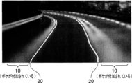
- the image after adding the blur for example, even if the traveling lane line is an intermittent double line, the entire traveling lane line looks like one thick line, so the recognized traveling lane line is discontinuous, It doesn't become a chigu-ha-guna line.
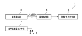
- the travel lane marking recognition device 1 is an in-vehicle device mounted on a vehicle, and an image photographing unit 3 that acquires an image including a road surface in front of the vehicle (hereinafter referred to as a road surface image) (an “image acquisition device” in the claims). ), An image processing unit 5 (“image processing device” in the claims) that recognizes a travel lane line (for example, a white line) by performing image processing on the road surface image acquired by the image capturing unit 3,
- the vehicle state quantity sensor unit 7 for detecting the yaw rate and the alarm / vehicle control unit 9 are provided.
- the image capturing unit 3 is a camera such as a camera using a CCD camera or an imaging tube, or an infrared camera capable of acquiring an infrared image.
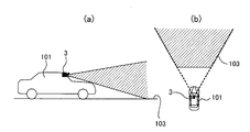
- the image photographing unit 3 is mounted on the front side of the center of the vehicle 101 and includes an image including a road surface 103 in front of the vehicle 101 (hereinafter referred to as a road image 105). Is repeatedly taken at predetermined time intervals (in this embodiment, every 0.1 second). Information on the road surface image 105 photographed by the image photographing unit 3 is output to the image processing unit 5.
- the image processing unit 5 is a well-known microcomputer including a CPU (processor), a ROM, a RAM, an I / O, a bus line connecting these, and the like (not shown).
- the alarm / vehicle control unit 9 performs an operation for driving support based on the traveling lane line recognized by the image processing unit 5 and the traveling speed and yaw rate detected by the vehicle state quantity sensor unit 7. Specifically, a lane departure warning is performed based on the lane marking. This lane departure warning calculates the distance in the horizontal direction from the vehicle to the left and right lane markings, and if either is below the threshold, that is, the vehicle is set to a threshold with respect to the lane marking This is a control to give an alarm to the driver when approaching.
- the alarm / vehicle control unit 9 performs steering assist control and a collision alarm based on the travel lane marking.
- Steering support control is control that assists the steering operation according to the lane in the traveling direction of the vehicle.
- Collision warning gives a warning to the driver when the distance from another vehicle preceding the same lane approaches. Control.
- traveling Lane Line Recognition Device 1 Processing executed by the traveling lane line recognition device 1 will be described with reference to FIGS.
- the traveling lane marking recognition device 1 repeatedly executes the process shown in the flowchart of FIG. 3 while power is supplied (while the ignition of the vehicle is ON).
- the image capturing unit 3 acquires the road surface image 105.
- the road surface image 105 includes a road surface 103 in front of the vehicle.
- the travel lane line 107 exists on the road surface 103
- the travel lane line 107 is also included in the road surface image 105.
- the road surface image 105 is output to the image processing unit 5.
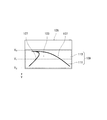
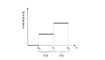
- the Y coordinate shown in FIG. 4 is a coordinate in a direction from the top (far) to the bottom (close to the vehicle) in the road surface image 105.
- a range 109 with Y coordinates Y 0 to Y 2 is a range representing the road surface 103.
- a range 111 with Y coordinates Y 1 to Y 2 is a predetermined road surface range near the vehicle on the road surface 103, and a range 113 with Y coordinates Y 0 to Y 1 is a range 111 on the road surface 103. It is a road surface range farther away. Since the attachment position, attachment angle, and imaging range of the image capturing unit 3 are constant, the range 109 in which the road surface 103 is displayed in the road image 105 is substantially constant.
- the image processing unit 5 performs a process of adding blur to the range 109 in which the road surface 103 is displayed in the road surface image 105 acquired in step 1.
- the process of adding a blur is a process of making the boundary line of an object (for example, a travel lane line) displayed in an image ambiguous (unclear).
- An example of the process for adding blur is an averaging process.
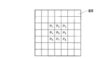
- each rectangular section in FIG. 5 represents one pixel of the road surface image 105.
- the luminance of the pixels P 0 is converted to an average value of the luminance of the pixel P 0 and surrounding pixels P 1 ⁇ P 8. Similar processing is performed for each pixel belonging to the range 109.
- the range of pixels (number of pixels) to be averaged in the averaging process is not limited to that shown in FIG. 5 and can be arbitrarily set.
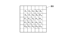
- the luminance of the pixels P 0, it can be converted to an average value of the luminance of the pixel P 0 and surrounding pixels P 0 ⁇ P 24.
- the weight of each pixel can be arbitrarily set. For example, in the example shown in FIG. 6, when determining the luminance of the pixel P 0, the weighting of the pixels P 0, P 7, P 8 , P 9, P 12, P 13, P 16, P 17, P 18 proximate The weight may be increased, the weights of other pixels may be decreased, or the weights of all the pixels may be made uniform.
- the averaging process can be executed using a dedicated filter.
- the larger the range of pixels to be averaged the larger the added blur. That is, the processed image becomes more ambiguous or unclear.
- the luminance of the pixels P 0, rather than converting the average value of the luminance of the pixel P 0 and surrounding pixels P 1 ⁇ P 8, the luminance of the pixels P 0, the pixel P
- the blurring to be added becomes larger when converted to the average value of the luminance of 0 and the surrounding pixels P 0 to P 24 .
- step 2 the above-described averaging process is performed on each pixel in the range 109 where the road surface 103 is displayed in the road surface image 105, and blur is added to the road surface image 105.
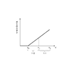
- the degree of blur to be added (in other words, the range of pixels that are averaged in the averaging process) is set to a different value depending on the position of each pixel in the Y coordinate. More specifically, as shown in FIG. 7, the blur added at the position of the Y coordinate at Y 0 is the smallest, and the blur added gradually increases as it approaches Y 2 .
- a larger blur is added to the predetermined road surface range 111 closer to the vehicle than the road surface range 113 farther away. Further, the amount of blur to be added is larger as it is closer to the vehicle.
- the size of the blur is the sum of the size of the blur determined by the characteristics of the image capturing unit 3 (particularly the characteristics of the lens) and the size of the blur added by the averaging processing (hereinafter referred to as the blur size). , The sum of blurs).
- the additional amount of blur is set so that the sum of the blur is constantly constant in each of the predetermined road surface range 111 closer to the vehicle and the road surface range 113 farther than that. Yes.
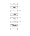
- step 3 the image processing unit 5 performs edge extraction processing, which is known image processing, on the road surface image 105 to which blur has been added in step 2, and extracts edge points.
- step 4 the image processing unit 5 performs a Hough transform on the edge points extracted in step 3 to detect a straight line.
- step 5 the image processing unit 5 calculates a straight line detected in step 4 with a large number of votes for Hough conversion as a running lane line candidate.
- the image processing unit 5 narrows down the travel lane line candidates. Specifically, for example, the ratio of the contrast of the running lane line candidate to the surrounding road surface is higher than a predetermined threshold, or the difference between the luminance of the running lane line candidate portion and the surrounding luminance is equal to or larger than the predetermined threshold. Are larger than the lane marking candidates. In addition, it may be narrowed down in consideration of various characteristics such as line thickness and total extension distance. Then, in the left-right direction from the center of the vehicle, one closest lane marking candidate is selected, and the selected lane marking candidate is recognized as the left and right lane markings. The recognized left and right travel lane markings are output to the alarm / vehicle control unit 9.
- the travel lane marking recognition device 1 adds blur to the road surface image 105, and recognizes the travel lane marking using the road surface image 105 after the blur is added. For example, as shown in FIG. 10, the road surface image 105 after adding the blur is recognized as a single thick line as a whole even if the traveling division line is an intermittent double line. The traveling lane line 20 is not discontinuous and does not become a tangled line.
- the travel lane marking recognition device 1 adds a larger blur to a predetermined road surface range 111 closer to the vehicle than the road surface range 113 farther away from the road image 105. Further, the size of the added blur is larger as it is closer to the vehicle.
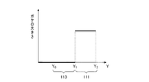
- the relationship between the size of blur to be added (range of pixels to be averaged in the averaging process, that is, the number of pixels) and the position of each pixel in the Y coordinate is the graph of FIG.
- the relationship defined by the graph of 9 may be sufficient.
- the graph of FIG. 8 is a case where a blur having a certain size is selectively added only to a predetermined road surface range 111 closer to the vehicle. “Selective” refers to adding blur only when the vehicle encounters intermittent double lane markings. Also in this case, it is possible to prevent the intermittent double line recognized in the predetermined road surface range 111 close to the vehicle from becoming a discontinuous or short line.
- the traveling lane marking recognition device 1 does not necessarily include the alarm / vehicle control unit 9.
- the information on the travel lane markings recognized by the image capturing unit 5 can be output to the outside (another device mounted on the vehicle or a device outside the vehicle).
- the process for adding blur can be selected as appropriate in addition to the averaging process.
- a method for reducing the resolution of an image can be used.
- step 2 blur may be added to the entire road surface image 105 including a farther range than the far road surface range 113.
- the amount of blur to be added may be increased as it gets closer to the vehicle, or may be equal.
- the averaging process can be performed using a filter in which an averaging process filter and another target filter (for example, a filter for emphasizing edges) are integrated. .
Landscapes
- Physics & Mathematics (AREA)
- General Physics & Mathematics (AREA)
- Engineering & Computer Science (AREA)
- Theoretical Computer Science (AREA)
- Multimedia (AREA)
- Traffic Control Systems (AREA)
- Image Analysis (AREA)
- Image Processing (AREA)
Priority Applications (1)
| Application Number | Priority Date | Filing Date | Title |
|---|---|---|---|
| US14/397,014 US9317940B2 (en) | 2012-04-26 | 2013-04-23 | Cruising zone division line recognition apparatus |
Applications Claiming Priority (2)
| Application Number | Priority Date | Filing Date | Title |
|---|---|---|---|
| JP2012101582A JP2013228944A (ja) | 2012-04-26 | 2012-04-26 | 走行区画線認識装置 |
| JP2012-101582 | 2012-04-26 |
Publications (1)
| Publication Number | Publication Date |
|---|---|
| WO2013161817A1 true WO2013161817A1 (ja) | 2013-10-31 |
Family
ID=49483126
Family Applications (1)
| Application Number | Title | Priority Date | Filing Date |
|---|---|---|---|
| PCT/JP2013/061923 Ceased WO2013161817A1 (ja) | 2012-04-26 | 2013-04-23 | 走行区画線認識装置 |
Country Status (3)
| Country | Link |
|---|---|
| US (1) | US9317940B2 (enExample) |
| JP (1) | JP2013228944A (enExample) |
| WO (1) | WO2013161817A1 (enExample) |
Citations (4)
| Publication number | Priority date | Publication date | Assignee | Title |
|---|---|---|---|---|
| JP2003323627A (ja) * | 2002-04-30 | 2003-11-14 | Nissan Motor Co Ltd | 車両検出装置及び方法 |
| JP2006260358A (ja) * | 2005-03-18 | 2006-09-28 | Honda Elesys Co Ltd | 車線認識装置 |
| JP2008013081A (ja) * | 2006-07-07 | 2008-01-24 | Nec Engineering Ltd | 車両自動走行システム |
| JP2011076248A (ja) * | 2009-09-29 | 2011-04-14 | Honda Motor Co Ltd | 走行区分線検出装置 |
Family Cites Families (3)
| Publication number | Priority date | Publication date | Assignee | Title |
|---|---|---|---|---|
| JP4032727B2 (ja) | 2001-12-12 | 2008-01-16 | アイシン精機株式会社 | 車線境界検出装置 |
| JP3864945B2 (ja) | 2003-09-24 | 2007-01-10 | アイシン精機株式会社 | 路面走行レーン検出装置 |
| JP5926080B2 (ja) | 2012-03-19 | 2016-05-25 | 株式会社日本自動車部品総合研究所 | 走行区画線認識装置およびプログラム |
-
2012
- 2012-04-26 JP JP2012101582A patent/JP2013228944A/ja active Pending
-
2013
- 2013-04-23 WO PCT/JP2013/061923 patent/WO2013161817A1/ja not_active Ceased
- 2013-04-23 US US14/397,014 patent/US9317940B2/en not_active Expired - Fee Related
Patent Citations (4)
| Publication number | Priority date | Publication date | Assignee | Title |
|---|---|---|---|---|
| JP2003323627A (ja) * | 2002-04-30 | 2003-11-14 | Nissan Motor Co Ltd | 車両検出装置及び方法 |
| JP2006260358A (ja) * | 2005-03-18 | 2006-09-28 | Honda Elesys Co Ltd | 車線認識装置 |
| JP2008013081A (ja) * | 2006-07-07 | 2008-01-24 | Nec Engineering Ltd | 車両自動走行システム |
| JP2011076248A (ja) * | 2009-09-29 | 2011-04-14 | Honda Motor Co Ltd | 走行区分線検出装置 |
Also Published As
| Publication number | Publication date |
|---|---|
| US20150104063A1 (en) | 2015-04-16 |
| US9317940B2 (en) | 2016-04-19 |
| JP2013228944A (ja) | 2013-11-07 |
Similar Documents
| Publication | Publication Date | Title |
|---|---|---|
| US8391555B2 (en) | Lane recognition apparatus for vehicle, vehicle thereof, and lane recognition program for vehicle | |
| EP2927060B1 (en) | On-vehicle image processing device | |
| JP4992990B2 (ja) | 区画線検出装置 | |
| JP5966965B2 (ja) | 車線境界線逸脱抑制装置及び車線境界線逸脱抑制方法 | |
| US10147003B2 (en) | Lane detection device and method thereof, curve starting point detection device and method thereof, and steering assistance device and method thereof | |
| US10635911B2 (en) | Apparatus and method for recognizing travel lane | |
| CN102016921A (zh) | 图像处理装置 | |
| JP4744537B2 (ja) | 走行レーン検出装置 | |
| JP2011243161A (ja) | 車線境界検出装置、車線境界検出プログラム | |
| US20120229644A1 (en) | Edge point extracting apparatus and lane detection apparatus | |
| JP2012252501A (ja) | 走行路認識装置及び走行路認識用プログラム | |
| JP6032141B2 (ja) | 走行路面標示検知装置および走行路面標示検知方法 | |
| JP5541099B2 (ja) | 道路区画線認識装置 | |
| US10906540B2 (en) | Vehicle control apparatus | |
| JP6495742B2 (ja) | 対象物検出装置、対象物検出方法、及び、対象物検出プログラム | |
| WO2018088262A1 (ja) | 駐車枠認識装置 | |
| KR20150042417A (ko) | 촬영부를 이용한 차선검출방법 및 차선검출시스템 | |
| JP2015121954A (ja) | 輝度値算出装置及び車線検出システム | |
| WO2013161817A1 (ja) | 走行区画線認識装置 | |
| JP2005301892A (ja) | 複数のカメラによるレーン認識装置 | |
| JP2012155399A (ja) | 境界検出装置、および境界検出プログラム | |
| JP6729358B2 (ja) | 認識装置 | |
| JP4956841B2 (ja) | 車両用画像処理装置、車両、及び車両用画像処理プログラム | |
| JP6564682B2 (ja) | 対象物検出装置、対象物検出方法、及び、対象物検出プログラム | |
| JP2016148883A (ja) | 画像処理装置、車両の諸元算出方法、および車両の諸元算出プログラム |
Legal Events
| Date | Code | Title | Description |
|---|---|---|---|
| 121 | Ep: the epo has been informed by wipo that ep was designated in this application |
Ref document number: 13781293 Country of ref document: EP Kind code of ref document: A1 |
|
| WWE | Wipo information: entry into national phase |
Ref document number: 14397014 Country of ref document: US |
|
| NENP | Non-entry into the national phase |
Ref country code: DE |
|
| 122 | Ep: pct application non-entry in european phase |
Ref document number: 13781293 Country of ref document: EP Kind code of ref document: A1 |