WO2013161415A1 - Engine control device - Google Patents
Engine control device Download PDFInfo
- Publication number
- WO2013161415A1 WO2013161415A1 PCT/JP2013/056897 JP2013056897W WO2013161415A1 WO 2013161415 A1 WO2013161415 A1 WO 2013161415A1 JP 2013056897 W JP2013056897 W JP 2013056897W WO 2013161415 A1 WO2013161415 A1 WO 2013161415A1
- Authority
- WO
- WIPO (PCT)
- Prior art keywords
- engine
- ion signal
- combustion
- cylinder temperature
- misfire
- Prior art date
Links
Images


Classifications
-
- G—PHYSICS
- G01—MEASURING; TESTING
- G01L—MEASURING FORCE, STRESS, TORQUE, WORK, MECHANICAL POWER, MECHANICAL EFFICIENCY, OR FLUID PRESSURE
- G01L23/00—Devices or apparatus for measuring or indicating or recording rapid changes, such as oscillations, in the pressure of steam, gas, or liquid; Indicators for determining work or energy of steam, internal-combustion, or other fluid-pressure engines from the condition of the working fluid
- G01L23/22—Devices or apparatus for measuring or indicating or recording rapid changes, such as oscillations, in the pressure of steam, gas, or liquid; Indicators for determining work or energy of steam, internal-combustion, or other fluid-pressure engines from the condition of the working fluid for detecting or indicating knocks in internal-combustion engines; Units comprising pressure-sensitive members combined with ignitors for firing internal-combustion engines
- G01L23/221—Devices or apparatus for measuring or indicating or recording rapid changes, such as oscillations, in the pressure of steam, gas, or liquid; Indicators for determining work or energy of steam, internal-combustion, or other fluid-pressure engines from the condition of the working fluid for detecting or indicating knocks in internal-combustion engines; Units comprising pressure-sensitive members combined with ignitors for firing internal-combustion engines for detecting or indicating knocks in internal combustion engines
- G01L23/225—Devices or apparatus for measuring or indicating or recording rapid changes, such as oscillations, in the pressure of steam, gas, or liquid; Indicators for determining work or energy of steam, internal-combustion, or other fluid-pressure engines from the condition of the working fluid for detecting or indicating knocks in internal-combustion engines; Units comprising pressure-sensitive members combined with ignitors for firing internal-combustion engines for detecting or indicating knocks in internal combustion engines circuit arrangements therefor
-
- F—MECHANICAL ENGINEERING; LIGHTING; HEATING; WEAPONS; BLASTING
- F02—COMBUSTION ENGINES; HOT-GAS OR COMBUSTION-PRODUCT ENGINE PLANTS
- F02D—CONTROLLING COMBUSTION ENGINES
- F02D13/00—Controlling the engine output power by varying inlet or exhaust valve operating characteristics, e.g. timing
- F02D13/02—Controlling the engine output power by varying inlet or exhaust valve operating characteristics, e.g. timing during engine operation
-
- F—MECHANICAL ENGINEERING; LIGHTING; HEATING; WEAPONS; BLASTING
- F02—COMBUSTION ENGINES; HOT-GAS OR COMBUSTION-PRODUCT ENGINE PLANTS
- F02D—CONTROLLING COMBUSTION ENGINES
- F02D35/00—Controlling engines, dependent on conditions exterior or interior to engines, not otherwise provided for
- F02D35/02—Controlling engines, dependent on conditions exterior or interior to engines, not otherwise provided for on interior conditions
- F02D35/021—Controlling engines, dependent on conditions exterior or interior to engines, not otherwise provided for on interior conditions using an ionic current sensor
-
- F—MECHANICAL ENGINEERING; LIGHTING; HEATING; WEAPONS; BLASTING
- F02—COMBUSTION ENGINES; HOT-GAS OR COMBUSTION-PRODUCT ENGINE PLANTS
- F02D—CONTROLLING COMBUSTION ENGINES
- F02D35/00—Controlling engines, dependent on conditions exterior or interior to engines, not otherwise provided for
- F02D35/02—Controlling engines, dependent on conditions exterior or interior to engines, not otherwise provided for on interior conditions
- F02D35/025—Controlling engines, dependent on conditions exterior or interior to engines, not otherwise provided for on interior conditions by determining temperatures inside the cylinder, e.g. combustion temperatures
- F02D35/026—Controlling engines, dependent on conditions exterior or interior to engines, not otherwise provided for on interior conditions by determining temperatures inside the cylinder, e.g. combustion temperatures using an estimation
-
- F—MECHANICAL ENGINEERING; LIGHTING; HEATING; WEAPONS; BLASTING
- F02—COMBUSTION ENGINES; HOT-GAS OR COMBUSTION-PRODUCT ENGINE PLANTS
- F02D—CONTROLLING COMBUSTION ENGINES
- F02D35/00—Controlling engines, dependent on conditions exterior or interior to engines, not otherwise provided for
- F02D35/02—Controlling engines, dependent on conditions exterior or interior to engines, not otherwise provided for on interior conditions
- F02D35/027—Controlling engines, dependent on conditions exterior or interior to engines, not otherwise provided for on interior conditions using knock sensors
-
- F—MECHANICAL ENGINEERING; LIGHTING; HEATING; WEAPONS; BLASTING
- F02—COMBUSTION ENGINES; HOT-GAS OR COMBUSTION-PRODUCT ENGINE PLANTS
- F02P—IGNITION, OTHER THAN COMPRESSION IGNITION, FOR INTERNAL-COMBUSTION ENGINES; TESTING OF IGNITION TIMING IN COMPRESSION-IGNITION ENGINES
- F02P17/00—Testing of ignition installations, e.g. in combination with adjusting; Testing of ignition timing in compression-ignition engines
- F02P17/12—Testing characteristics of the spark, ignition voltage or current
-
- G—PHYSICS
- G01—MEASURING; TESTING
- G01M—TESTING STATIC OR DYNAMIC BALANCE OF MACHINES OR STRUCTURES; TESTING OF STRUCTURES OR APPARATUS, NOT OTHERWISE PROVIDED FOR
- G01M15/00—Testing of engines
- G01M15/04—Testing internal-combustion engines
- G01M15/10—Testing internal-combustion engines by monitoring exhaust gases or combustion flame
- G01M15/102—Testing internal-combustion engines by monitoring exhaust gases or combustion flame by monitoring exhaust gases
-
- F—MECHANICAL ENGINEERING; LIGHTING; HEATING; WEAPONS; BLASTING
- F02—COMBUSTION ENGINES; HOT-GAS OR COMBUSTION-PRODUCT ENGINE PLANTS
- F02D—CONTROLLING COMBUSTION ENGINES
- F02D2200/00—Input parameters for engine control
- F02D2200/02—Input parameters for engine control the parameters being related to the engine
- F02D2200/10—Parameters related to the engine output, e.g. engine torque or engine speed
- F02D2200/1015—Engines misfires
-
- F—MECHANICAL ENGINEERING; LIGHTING; HEATING; WEAPONS; BLASTING
- F02—COMBUSTION ENGINES; HOT-GAS OR COMBUSTION-PRODUCT ENGINE PLANTS
- F02D—CONTROLLING COMBUSTION ENGINES
- F02D35/00—Controlling engines, dependent on conditions exterior or interior to engines, not otherwise provided for
- F02D35/02—Controlling engines, dependent on conditions exterior or interior to engines, not otherwise provided for on interior conditions
- F02D35/028—Controlling engines, dependent on conditions exterior or interior to engines, not otherwise provided for on interior conditions by determining the combustion timing or phasing
-
- F—MECHANICAL ENGINEERING; LIGHTING; HEATING; WEAPONS; BLASTING
- F02—COMBUSTION ENGINES; HOT-GAS OR COMBUSTION-PRODUCT ENGINE PLANTS
- F02D—CONTROLLING COMBUSTION ENGINES
- F02D37/00—Non-electrical conjoint control of two or more functions of engines, not otherwise provided for
- F02D37/02—Non-electrical conjoint control of two or more functions of engines, not otherwise provided for one of the functions being ignition
-
- F—MECHANICAL ENGINEERING; LIGHTING; HEATING; WEAPONS; BLASTING
- F02—COMBUSTION ENGINES; HOT-GAS OR COMBUSTION-PRODUCT ENGINE PLANTS
- F02P—IGNITION, OTHER THAN COMPRESSION IGNITION, FOR INTERNAL-COMBUSTION ENGINES; TESTING OF IGNITION TIMING IN COMPRESSION-IGNITION ENGINES
- F02P17/00—Testing of ignition installations, e.g. in combination with adjusting; Testing of ignition timing in compression-ignition engines
- F02P17/12—Testing characteristics of the spark, ignition voltage or current
- F02P2017/125—Measuring ionisation of combustion gas, e.g. by using ignition circuits
-
- Y—GENERAL TAGGING OF NEW TECHNOLOGICAL DEVELOPMENTS; GENERAL TAGGING OF CROSS-SECTIONAL TECHNOLOGIES SPANNING OVER SEVERAL SECTIONS OF THE IPC; TECHNICAL SUBJECTS COVERED BY FORMER USPC CROSS-REFERENCE ART COLLECTIONS [XRACs] AND DIGESTS
- Y02—TECHNOLOGIES OR APPLICATIONS FOR MITIGATION OR ADAPTATION AGAINST CLIMATE CHANGE
- Y02T—CLIMATE CHANGE MITIGATION TECHNOLOGIES RELATED TO TRANSPORTATION
- Y02T10/00—Road transport of goods or passengers
- Y02T10/10—Internal combustion engine [ICE] based vehicles
- Y02T10/12—Improving ICE efficiencies
Definitions
- the present invention relates to an engine control device, and more particularly to an abnormal combustion detection device using an ion signal.
- the average value of ion signals for the past several cycles is set as the background level, and a method of calculating the determination threshold based on the background level is taken, but when the engine load or the rotation speed changes, There is a problem that a certain delay occurs in the change of the determination threshold value.
- an ionic current value (background) at the time of normal combustion is stored on an engine operation map with the engine load and the rotational speed as axes, and a knock determination threshold value is set based on the value.
- a method of correcting and updating the determination threshold value for each driving region by learning is known.
- the in-cylinder state (gas composition or temperature) deviates transiently from steady operating conditions centered on the engine load and speed. ).
- the actual value of the EGR rate is overshoot or undershoot with respect to the target value.
- an in-cylinder state gas composition and gas temperature
- abnormal combustion is erroneously determined as abnormal combustion (knock, misfire).
- abnormal combustion knock, misfire
- an object of the present invention is to control an engine that can accurately determine knocking or misfire under any operating condition, including a transient condition in which the in-cylinder state rapidly changes.
- the engine control apparatus of the present invention comprises an ion signal detection means for detecting ions generated during combustion, and an abnormality for determining knock or misfire based on the ion signal detected by the detection means.
- An engine control device comprising a combustion determination means, comprising: an in-cylinder temperature estimating means for estimating an in-cylinder temperature of a normal combustion cycle under the current operating condition of the engine, and knocking an ion signal based on the estimated in-cylinder temperature information It is characterized by setting a judgment threshold value or a misfire judgment threshold value.
- in-cylinder temperature information correlated with the ion signal value is estimated for each cycle, and a determination threshold value is set based on the temperature information, thereby suppressing erroneous determination under any operating condition and causing abnormalities. It becomes possible to improve the detection accuracy of combustion.
- the in-cylinder temperature estimation means is configured to open and close an intake valve and an exhaust valve that control pressure inside the intake pipe of the engine and intake and exhaust of the engine.
- In-cylinder temperature is estimated using at least one of a timing, an air-fuel ratio that is a mass ratio of air and fuel supplied to the combustion chamber of the engine, and an ignition signal for controlling the ignition timing of the engine It is characterized by.
- in-cylinder temperature estimation allows more accurate in-cylinder temperature estimation by taking into account engine control parameter values that directly affect the in-cylinder temperature such as the intake / exhaust valve, air-fuel ratio, and ignition timing. .
- the abnormal combustion determination means is based on an integral value of an ion signal for a predetermined period in a combustion cycle or a peak value of an ion signal within a predetermined period. It is characterized by determining knock or misfire.
- the abnormal combustion determination means determines that the engine is knocking or misfiring, of the ignition timing of the engine and the closing timing of the intake valve, It is characterized by changing at least one.
- the engine control device further includes a steady operation determination unit that determines whether the current engine operation state is a steady operation state, and the steady operation determination unit determines that the operation is not steady operation.
- a knock determination threshold value or a misfire determination threshold value of the ion signal is set based on the in-cylinder temperature information.
- in-cylinder temperature estimation is performed because abnormal combustion determination based on the estimated in-cylinder temperature information is performed only under conditions that are determined not to be steady conditions, that is, transient conditions in which the behavior of in-cylinder gas changes significantly. Therefore, it is possible to minimize the increase in the calculation load on the ECU.
- the present invention even in a transient condition in which the in-cylinder state changes rapidly, by setting the abnormal combustion determination threshold value of the ionic current based on the estimated in-cylinder temperature information, knocking and misfire can be accurately performed. Thus, abnormal combustion can be minimized.
- the system block diagram of the control apparatus of the engine by the 1st Embodiment of this invention The ignition system block diagram of the control apparatus of the engine by the 1st Embodiment of this invention.
- Explanatory drawing of the knock detection principle of the abnormal combustion determination method of the control apparatus of the engine by the 1st Embodiment of this invention Explanatory drawing of the knock detection principle of the abnormal combustion determination method of the control apparatus of the engine by the 1st Embodiment of this invention.
- the system block diagram which shows the structure of the control apparatus of the engine by the 1st Embodiment of this invention.
- 1 is a schematic diagram of abnormal combustion determination and avoidance control logic that is performed in an ECU of an engine control apparatus according to a first embodiment of the present invention.
- the flowchart which shows the abnormal combustion determination by the ion signal of the engine control apparatus by the 1st Embodiment of this invention, and the avoidance control content.
- the system block diagram of the control apparatus of the engine by the 2nd Embodiment of this invention The representative example of the ignition signal and ion signal of the control apparatus of the engine by the 2nd Embodiment of this invention.
- the system block diagram which shows the structure of the control apparatus of the engine by the 2nd Embodiment of this invention.
- the schematic diagram of the abnormal combustion determination and avoidance control logic implemented within ECU of the control apparatus of the engine by the 2nd Embodiment of this invention.
- the flowchart which shows the abnormal combustion determination and the avoidance control content by the ion signal of the control apparatus of the engine by the 2nd Embodiment of this invention.
- the flowchart which shows the abnormal combustion determination and the avoidance control content by the ion signal of the control apparatus of the engine by the 3rd Embodiment of this invention.
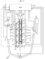
- FIG. 1 is a system configuration diagram showing the configuration of a system in which an engine control apparatus according to a first embodiment of the present invention is applied to an in-cylinder gasoline injection engine for automobiles.
- Engine 100 is a four-cylinder gasoline engine for automobiles that performs spark ignition combustion.
- An airflow sensor 1 that measures the amount of intake air
- an electronic control throttle 2 that adjusts the intake pipe pressure
- an intake air temperature sensor 15 that is an aspect of the intake air temperature detector and measures the temperature of intake air
- An intake pressure sensor 21 for measuring the pressure in the pipe is provided at an appropriate position of each intake pipe 6.
- the engine 100 is provided with a fuel injection device (hereinafter referred to as an injector 3) for injecting fuel into the combustion chamber 12 of each cylinder and an ignition system 4 for supplying ignition energy for each cylinder.
- a cooling water temperature sensor 14 for measuring the temperature of the cylinder head 7 is provided at an appropriate position.
- Each of the cylinder heads 7 includes a variable valve 5 including an intake valve variable device 5a for adjusting the intake gas flowing into the cylinder and an exhaust valve variable device 5b for adjusting the exhaust gas discharged from the cylinder.
- a variable valve 5 including an intake valve variable device 5a for adjusting the intake gas flowing into the cylinder and an exhaust valve variable device 5b for adjusting the exhaust gas discharged from the cylinder.
- a high-pressure fuel pump 17 for supplying high-pressure fuel to the injector 3 is connected to the injector 3 by a fuel pipe.
- a fuel pressure sensor 18 for measuring the fuel injection pressure is provided in the fuel pipe.
- a three-way catalyst 10 for purifying exhaust and an air-fuel ratio detector, an air-fuel ratio sensor 9 for detecting the air-fuel ratio of the exhaust on the upstream side of the three-way catalyst 10, and an exhaust temperature detector
- an exhaust temperature sensor 11 that measures the temperature of the exhaust gas upstream of the three-way catalyst 10 is provided at each appropriate position of the exhaust pipe 8.
- the crankshaft is provided with a crank angle sensor 13 for calculating the rotation angle.
- a signal obtained from the variable valve 5 (phase angle sensor) is sent to an engine control unit (ECU) 20. Further, a signal obtained from the accelerator opening sensor 16 is sent to the ECU 20.
- the accelerator opening sensor 16 detects the amount of depression of the accelerator pedal, that is, the accelerator opening.
- the ECU 20 calculates the required torque based on the output signal of the accelerator opening sensor 16. That is, the accelerator opening sensor 16 is used as a required torque detection sensor that detects a required torque for the engine.
- the ECU 20 calculates the rotational speed of the engine based on the output signal of the crank angle sensor 13.
- the ECU 20 optimally calculates main operating amounts of the engine such as the air flow rate, the fuel injection amount, the ignition timing, and the fuel pressure based on the operating state of the engine obtained from the outputs of the various sensors.
- the fuel injection amount calculated by the ECU 20 is converted into a valve opening pulse signal and sent to the injector 3. Further, an ignition signal 4h is sent to the ignition system 4 so as to be ignited at the ignition timing calculated by the ECU 20.
- the throttle opening calculated by the ECU 20 is sent to the electronic control throttle 2 as a throttle drive signal. Further, the operation amount of the variable valve calculated by the ECU 20 is sent to the variable valve 5 as a variable valve drive signal.
- the fuel pressure calculated by the ECU 20 is sent to the high pressure fuel pump 17 as a high pressure fuel pump drive signal.
- Fuel is injected from the intake pipe 6 through the intake valve into the combustion chamber 12 to form an air-fuel mixture.
- the air-fuel mixture explodes by a spark generated from the spark plug 4a at a predetermined ignition timing, and the piston is pushed down by the combustion pressure to become the driving force of the engine. Further, the exhaust gas after the explosion is sent to the three-way catalyst 10 through the exhaust pipe 8, and the exhaust components are purified in the three-way catalyst 10 and discharged to the outside.
- FIG. 2 is a diagram showing a configuration of the ignition system 4 of the engine control apparatus according to the first embodiment of the present invention.
- a current flows through the primary ignition coil 4c via the igniter 4i.
- an electromotive force is generated in the secondary ignition coil 4b, a high voltage is applied to the tip of the spark plug 4a, and spark discharge occurs.
- spark discharge current flows in the direction of arrow I in the figure.
- the voltage of the secondary ignition coil 4b decreases and becomes lower than the breakdown voltage (for example, 100V) of the Zener diode 4e, the current flows into the capacitor 4d, and the capacitor 4d is charged.
- the breakdown voltage for example, 100V
- the spark discharge creates a flame kernel in the gap between the spark plugs, and then the flame propagates into the combustion chamber.
- ions such as chemical ions and thermal ions exist as intermediate products in the combustion process.
- a voltage in this case, 100 V
- ions are generated in the circuit.
- Current flows (direction II in the figure). This ionic current is voltage-converted by the voltage conversion resistor 4f and then sent to the ECU 20 as an ion signal 4g.
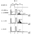
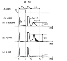
- FIG. 3 is a diagram showing representative examples of an ignition signal and an ion signal in the engine control apparatus according to the first embodiment of the present invention.
- the ion signal is characterized by three peaks.
- the first peak 4g-1 is a waveform that is seen when the ion signal detection circuit is built in the ignition system 4.
- a current flows through the ion signal detection unit and the ion flows.
- Output as a signal. In practice, this is treated as noise because there is no combustion flame in the combustion chamber.
- the second peak 4g-2 is a waveform that is seen after the ignition signal 4h is cut off at time t2 after the charging time ⁇ ta and a spark flies between the gaps of the spark plug 4a. Although the ion signal cannot be detected, the ion component in the initial combustion flame is subsequently detected.
- the third peak 4g-3 is a waveform that is detected when the combustion flame burns and spreads throughout the combustion chamber. It matches the pressure waveform in the combustion chamber and detects the ionic components in the flame of the main combustion portion. Yes.
- the integrated value of the signal at the third peak is used for determining abnormal combustion.
- the ignition signal 4h is interrupted at time t2, and the ion signal 4g from time t3 after the passage of ⁇ tb to time t4 after the passage of ⁇ tc is integrated. This is S (i).
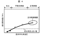
- FIG. 4 is an explanatory diagram of the misfire detection principle of the abnormal combustion determination method in the engine control apparatus according to the first embodiment of the present invention.
- the horizontal axis of the graph represents a value corresponding to the indicated mean effective pressure, that is, the engine torque, and the vertical axis represents the ion signal integrated value.
- the combustion state is stable, it is within the normal combustion range in the figure.
- the ion signal integrated value S (i) becomes small, and it can be determined that misfire occurs when the value falls below the set misfire determination threshold value.
- the black plot is a condition for determining a misfire. As described above, since the ion signal during normal combustion changes depending on operating conditions such as the engine speed, it is necessary to change the misfire determination threshold value depending on the operating conditions.
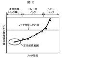
- FIG. 5 is an explanatory diagram of the knock detection principle of the abnormal combustion determination method in the engine control apparatus according to the first embodiment of the present invention.
- the horizontal axis of the graph is the knock intensity, for example, a value obtained by calculating the vibration intensity of the knock frequency component from the output signal of the knock sensor, and the vertical axis is the ion signal integrated value.
- the further to the left, the larger the knock strength, and the leftmost portion is a heavy knock state.
- knock does not occur, it is within the normal combustion range in the figure.
- the pressure / temperature in the combustion chamber rises and the ion signal integrated value S (i) increases.
- a knock can be determined when the set knock determination threshold is exceeded.
- Black plots in the figure are conditions for determining knocking. As described above, since the ion signal during normal combustion changes depending on operating conditions such as the engine speed, it is necessary to change the knock determination threshold value depending on the operating conditions.
- FIG. 6 is a diagram showing the relationship between the integrated value of the ion signal and the maximum temperature in the cylinder.
- the results obtained by changing various parameters such as engine load, engine speed, air-fuel ratio, EGR rate, etc. are plotted. From this figure, it is understood that the ion signal has a strong correlation with the maximum temperature in the cylinder, and the ion signal increases as the maximum temperature in the cylinder increases. For example, the deepest in-cylinder temperature rises under conditions where the engine load is large, so that the ion signal integrated value also increases. In addition, under a condition where the EGR rate is large, the heat capacity of the in-cylinder gas increases, so that the in-cylinder maximum temperature decreases and the ion signal integrated value decreases.
- the misfire and knock detection principles shown in FIGS. 4 and 5 also utilize the relationship between the in-cylinder maximum temperature and the ion signal.
- the engine control apparatus in the present embodiment predicts the maximum in-cylinder temperature during normal combustion in the target cycle, and calculates the ion signal during normal combustion using the relationship shown in FIG. Thereafter, an abnormal combustion determination threshold is calculated from the ion signal during normal combustion. For example, a value obtained by multiplying a signal during normal combustion by a constant is set as an abnormal combustion determination threshold value.
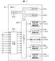
- FIG. 7 is a system block diagram showing the configuration of the engine control apparatus according to the first embodiment of the present invention.
- Airflow sensor 1, ion signal 4g, air-fuel ratio sensor 9, exhaust temperature sensor 11, crank angle sensor 13, cooling water temperature sensor 14, intake air temperature sensor 15, accelerator opening sensor 16, fuel pressure sensor 18, intake air pressure sensor 21, Is input to the input circuit 20a of the ECU 20.
- the input signal is not limited to these.
- the input signal of each input sensor is sent to the input port in the input / output port 20b.
- the value sent to the input / output port 20b is stored in the RAM 20c and processed by the CPU 20e.
- a control program describing the contents of the arithmetic processing is written in advance in the ROM 20d.
- the value indicating the operation amount of each actuator calculated in accordance with the control program is stored in the RAM 20c, then sent to the output port in the input / output port 20b, and sent to each actuator via each drive circuit.
- Each circuit controls the electronic control throttle 2, the injector 3, the ignition system 4, the variable valve 5, and the high-pressure fuel pump 17, respectively.
- the device includes the drive circuit in the ECU 20.
- the present invention is not limited to this, and any of the drive circuits may be provided in the ECU 20.
- ECU20 determines abnormal combustion based on an input signal, and when it determines with it being abnormal combustion, it controls ignition timing and a variable valve.
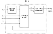
- FIG. 8 is a diagram showing an outline of the abnormal combustion determination and avoidance control logic executed in the ECU 20 of the engine control apparatus according to the first embodiment of the present invention. It comprises an ion signal processing unit, a knock / misfire determination unit, and a knock / misfire avoidance control unit.
- the ion signal 4g is input to the ion signal processing unit, and integration processing in a predetermined section is executed as shown in FIG.
- the knock / misfire determination unit includes the variable valve 5 to the current valve phase (especially the intake valve closing timing and the exhaust valve closing timing), the air-fuel ratio, the intake pipe pressure, and the ignition signal (ignition timing). Is entered.
- the maximum in-cylinder temperature during normal combustion is estimated based on the intake valve closing timing, the exhaust valve closing timing, the air-fuel ratio, the intake pipe pressure, and the ignition timing. Specifically, the in-cylinder air amount and the internal EGR amount are obtained from the exhaust valve closing timing and the intake pipe pressure.
- the in-cylinder temperature history of the air cycle in the compression / expansion stroke is obtained from the effective compression ratio obtained from the intake valve closing timing, the in-cylinder air amount, and the internal EGR amount. It is possible to estimate the maximum in-cylinder temperature during normal combustion based on the in-cylinder temperature history of this air cycle, the amount of heat generated during combustion obtained from the air-fuel ratio, and the combustion end timing that can be estimated from the ignition timing. it can.
- the ion signal integral value at the time of normal combustion is calculated using the relationship shown in FIG. 6, and the determination threshold value for knocking and misfire is calculated by multiplying it by a constant.
- Knock and misfire are determined by comparing the threshold value for determining knock and misfire with the input ion integration value. If it is determined that knocking 1 knock determination flag F k, is set to 1 misfire determination flag F m If it is determined that a misfire, and outputs the knock / misfire avoidance control section.
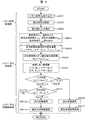
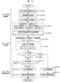
- FIG. 9 is a flowchart showing abnormal combustion determination and avoidance control contents based on ion signals in the engine control apparatus according to the first embodiment of the present invention.
- the control content shown in FIG. 9 is repeatedly executed by the ECU 20 at a predetermined cycle.
- step S901 the ECU 20 reads the ion signal 4g.
- step S902 a period for integrating the ion signal is set. Basically, the integration period is set from the elapse of a certain time (for example, 2 ms) from the ignition timing to the timing (for example, 90 deg. ATDC) at which combustion ends. This integration period is stored in advance as a map for each operating condition.
- step S903 an ion signal integrated value S (i) is calculated.
- the symbol i means the i-th cycle.
- the maximum in-cylinder temperature T max during normal combustion is calculated.
- the normal combustion ion signal integration value S b (i) is calculated from the maximum in-cylinder temperature T max during normal combustion.
- the ECU 20 stores in advance a formula (approximate formula) of the relationship between the maximum in-cylinder temperature and the ion signal shown in FIG. 6, and the calculation is performed using the formula.
- a knock determination threshold value S k (i) and a misfire determination threshold value S m (i) are calculated from the normal combustion ion signal integrated value S b (i). For example, a value obtained by multiplying a normal combustion ion signal integrated value S b (i) by a constant A, a knock determination threshold value S k (i), and a normal combustion ion signal integrated value S b (i) by a constant B.
- the multiplied value is defined as a misfire determination threshold value S m (i).
- A is set to about 1.2 to 2.0
- B is set to about 0.1 to 0.5.
- step S908 the ion signal integrated value S (i) and the knock determination threshold value S k (i) are compared to determine whether or not the knock is made. If S (i)> S k (i), it is determined that knocking has occurred, and the process proceeds to step S909. If S (i) ⁇ S k (i), it is determined that it is not knocking, and the process proceeds to step S911. In step S909, retard control of the ignition timing is performed in order to avoid knock, and in step S910, retard control of the intake valve close timing (decrease in the effective compression ratio) is performed in order to avoid knock. Then, a series of control is finished.
- step S911 by comparing the ion signal integral value S (i) and flameout determination threshold S m (i), determines whether or not misfire. If S (i) ⁇ S m (i), it is determined that there is no misfire, and the series of controls is terminated. If S (i) ⁇ S m (i), it is determined that a misfire has occurred, and the process proceeds to step S912. In step S912, ignition timing advance control is performed to avoid misfire, and in step S913, intake valve close timing advance control (increase in effective compression ratio) is performed to avoid misfire. Then, a series of control is finished.
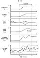
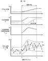
- FIG. 10 shows a time chart of the abnormal combustion determination by the ion signal by the engine control apparatus according to the first embodiment of the present invention. From the top in the figure, accelerator opening ⁇ , intake pipe pressure P in , air-fuel ratio A / F, intake valve closing timing ⁇ ivc , maximum in-cylinder temperature during normal combustion (estimated value) T max , ion signal integrated value S The time change of is shown. In the chart of the ion signal integrated value S, the normal combustion ion signal integrated value S b , the knock determination threshold value S k , and the misfire determination threshold value S m are also shown. In this example, it is assumed that no knock or misfire has occurred.
- an operation with a constant accelerator opening is performed, and the engine operating state (intake pipe pressure, air-fuel ratio, etc.) and the estimated maximum in-cylinder temperature during normal combustion are stable.
- the accelerator is depressed by the driver, first throttle is opened by receiving it, an intake pipe pressure starts rising.
- the intake pipe pressure rises with a certain time delay from the accelerator opening.
- the fuel injection amount is controlled so as to obtain a desired air-fuel ratio (for example, stoichiometric ratio) in accordance with the amount of air in the cylinder.
- the air-fuel ratio is In some cases, it may become temporarily rich.
- FIG. 11 is a system configuration diagram showing a system configuration in which the engine control apparatus according to the second embodiment of the present invention is applied to an in-cylinder gasoline injection engine for automobiles.
- a bypass passage between the exhaust pipe and the intake pipe is provided, and the exhaust amount flowing into the intake pipe is controlled in the passage.
- An EGR valve 19 is provided.
- FIG. 12 is a diagram showing a representative example of an ignition signal and an ion signal in the engine control apparatus according to the second embodiment of the present invention.
- the ion signals during normal combustion, knocking, and misfire are as shown in FIG.
- the pressure / temperature in the combustion chamber rises with the occurrence of knocking, so that the third peak signal becomes large, and a vibration component having a knocking frequency is on it.
- the peak value of the third peak signal is used for abnormal combustion determination in the present embodiment.
- the ignition signal 4h is cut off at time t2, and the peak value of the ion signal 4g from time t3 after the passage of ⁇ tb to time t4 after the passage of ⁇ tc is calculated. This is C (i).
- the determination principle of knocking and misfire using the ion signal in the present embodiment is the same as that described in FIGS. 4 to 6 (the ion signal integrated value may be replaced with the ion signal peak value).
- FIG. 13 is a system block diagram showing the configuration of the engine control apparatus according to the second embodiment of the present invention.
- the opening degree of the EGR valve 19 as an input signal and an EGR valve drive circuit 20l are provided. Is a feature.
- FIG. 14 is a diagram showing an outline of the abnormal combustion determination and avoidance control logic executed in the ECU 20 of the engine control apparatus according to the second embodiment of the present invention.
- the knock / misfire determination unit includes an EGR valve as an input signal.
- the calculation content in the ion signal processing unit is different from that in the first embodiment.
- the ion signal 4g is input to the ion signal processing unit, and the peak value of the ion signal in a predetermined section is output as shown in FIG.
- the knock / misfire determination unit starts from the variable valve 5 to the current valve phase (especially the intake valve closing timing and exhaust valve closing timing), the air-fuel ratio, the intake pipe pressure, and the ignition signal (ignition timing).
- EGR valve opening is input.
- the maximum in-cylinder temperature during normal combustion is estimated based on the intake valve closing timing, exhaust valve closing timing, air-fuel ratio, intake pipe pressure, ignition timing, and EGR valve opening.
- the in-cylinder air amount and the internal EGR amount are obtained from the exhaust valve closing timing, the intake pipe pressure, and the EGR valve opening.
- the in-cylinder temperature history of the air cycle in the compression / expansion stroke is obtained from the effective compression ratio obtained from the intake valve closing timing, the in-cylinder air amount, and the internal EGR amount. It is possible to estimate the maximum in-cylinder temperature during normal combustion based on the in-cylinder temperature history of this air cycle, the amount of heat generated during combustion obtained from the air-fuel ratio, and the combustion end timing that can be estimated from the ignition timing. it can. Based on the estimated maximum in-cylinder temperature at the time of normal combustion, the ion signal integral value at the time of normal combustion is calculated using the relationship shown in FIG.
- Knock and misfire are determined by comparing the threshold value for determining knock and misfire with the input ion integration value. If it is determined that knocking 1 knock determination flag F k, is set to 1 misfire determination flag F m If it is determined that a misfire, and outputs the knock / misfire avoidance control section.
- the knock / misfire avoidance control unit is the same as in the first embodiment.
- FIG. 15 is a flowchart showing abnormal combustion determination and avoidance control contents based on ion signals in the engine control apparatus according to the second embodiment of the present invention.
- the control content shown in FIG. 15 is repeatedly executed by the ECU 20 at a predetermined cycle.
- step S1501 the ECU 20 reads the ion signal 4g.
- step S1502 an ion signal calculation period is set. Basically, the calculation period is set from the elapse of a certain time (for example, 2 ms) from the ignition timing to the timing (for example, 90 deg. ATDC) at which combustion ends. This calculation period is stored in advance as a map for each operating condition.
- step S1503 an ion signal peak value C (i) is calculated.
- the symbol i means the i-th cycle.
- step S1507 it calculates a knock determination threshold value C k (i) and flameout determination threshold C m (i) from the normal combustion ion signal peak value C b (i).
- the normal combustion ion signal integrated value C b (i) multiplied by the constant A is set to the knock determination threshold C k (i)
- the normal combustion ion signal integrated value C b (i) is set to the constant B.
- the multiplied value is defined as a misfire determination threshold value C m (i).
- A is set to about 1.2 to 2.0
- B is set to about 0.1 to 0.5.
- step S1508 the ion signal peak value C (i) is compared with the knock determination threshold value C k (i) to determine whether or not it is a knock. If C (i)> C k (i), it is determined that knocking has occurred, and the process proceeds to step S1509. If C (i) ⁇ C k (i), it is determined that it is not knocking, and the process proceeds to step S1511. In step S1509, ignition timing retardation control is performed to avoid knocking, and in step S1510, intake valve closing timing retardation control (decrease in the effective compression ratio) is performed to avoid knocking. Then, a series of control is finished.
- step S1508 If it is determined in step S1508 that the engine is not knocked, the process proceeds to step S1511, and the ion signal peak value C (i) is compared with the misfire determination threshold value C m (i) to determine whether misfire has occurred. If C (i) ⁇ C m (i), it is determined that there is no misfire, and the series of controls is terminated. If C (i) ⁇ C m (i), it is determined that a misfire has occurred, and the process proceeds to step S1512. In step S1512, ignition timing advance control is performed in order to avoid misfire, and in step S1513, intake valve close timing advance control (increase in effective compression ratio) is performed in order to avoid misfire. Then, a series of control is finished.
- FIG. 16 shows a time chart of the abnormal combustion determination by the ion signal by the engine control apparatus according to the second embodiment of the present invention. From the top of the figure, accelerator opening ⁇ , intake pipe pressure P in , air-fuel ratio A / F, intake valve closing timing ⁇ ivc , EGR valve opening ⁇ , maximum in-cylinder temperature during normal combustion (estimated value) T max The time change of the ion signal peak value C is shown. In the chart of the ion signal peak value C, the normal combustion ion signal integrated value C b , the knock determination threshold value C k , and the misfire determination threshold value C m are also shown. In this example, it is assumed that no knock or misfire has occurred.
- the knock / misfire determination threshold value C k is C m is calculated. Since the measured ion signal integrated value C is within the range of C k ⁇ C ⁇ C m within the illustrated period, it is determined that there is no knock / misfire.
- the abnormal combustion judgment threshold value of the ion signal that follows the change of the transient engine state, especially the EGR rate behavior in the engine system with external EGR. It becomes possible to suppress.
- the configuration of a system in which the engine control apparatus according to the third embodiment of the present invention is applied to an in-cylinder gasoline injection engine for automobiles is the same as that shown in FIG.
- the system block diagram showing the configuration of the engine control apparatus according to the third embodiment of the present invention is the same as that shown in FIG.
- the determination principle of knocking and misfire using the ion signal in the present embodiment is the same as that described in FIGS. 4 to 6 (the ion signal integrated value may be replaced with the ion signal peak value).
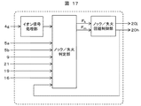
- FIG. 17 is a diagram showing an outline of the abnormal combustion determination and avoidance control logic executed in the ECU 20 of the engine control apparatus according to the third embodiment of the present invention.
- the knock / misfire determination unit is provided with an accelerator opening sensor 16 as an input signal. Is a feature. Based on the accelerator opening sensor 16, the knock / misfire determination unit determines whether or not the current operating state is a steady state, and changes the method for setting the knock / misfire determination threshold based on the result.
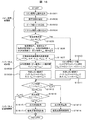
- step S1801 the ECU 20 reads the ion signal 4g.
- step S1802 an ion signal calculation period is set. Basically, the calculation period is set from the elapse of a certain time (for example, 2 ms) from the ignition timing to the timing (for example, 90 deg. ATDC) at which combustion ends. This calculation period is stored in advance as a map for each operating condition.
- step S1803 an ion signal peak value C (i) is calculated.
- the symbol i means the i-th cycle.
- step S1804 the accelerator opening ⁇ is read.
- step S1805 it is determined whether the current steady state is obtained by comparing the change amount d ⁇ / dt of the accelerator opening with the predetermined value X.
- step S1806 the intake pipe pressure P in , air-fuel ratio A / F, intake valve closing timing ⁇ IVC , exhaust valve closing timing ⁇ EVC , ignition
- the timing ⁇ spk and the EGR valve opening ⁇ are read.
- step S1807 the normal combustion maximum in-cylinder temperature Tmax is calculated from the read parameters. Specifically, first, the in-cylinder air amount and the internal EGR amount are obtained from the exhaust valve closing timing, the intake pipe pressure, and the EGR valve opening.
- the in-cylinder temperature history of the air cycle in the compression / expansion stroke is obtained from the effective compression ratio obtained from the intake valve closing timing, the in-cylinder air amount, and the internal EGR amount. Based on the in-cylinder temperature history of the air cycle, the amount of heat generated during combustion obtained from the air-fuel ratio, and the combustion end timing that can be estimated from the ignition timing, the maximum in-cylinder temperature T max during normal combustion is calculated. .
- the normal combustion ion signal peak value C b (i) is calculated from the maximum in-cylinder temperature T max during normal combustion.
- the ECU 20 stores in advance a formula (approximate formula) of the relationship between the maximum in-cylinder temperature and the ion signal shown in FIG. 6, and the calculation is performed using the formula.
- a knock determination threshold value C k (i) and a misfire determination threshold value C m (i) are calculated from the normal combustion ion signal peak value C b (i).
- the normal combustion ion signal integrated value C b (i) multiplied by the constant A is set to the knock determination threshold C k (i)
- the normal combustion ion signal integrated value C b (i) is set to the constant B.
- the multiplied value is defined as a misfire determination threshold value C m (i).
- A is set to about 1.2 to 2.0
- B is set to about 0.1 to 0.5.
- step S1810 the background level of the ion signal peak value is calculated.
- the background level means an average value of ion signal peak values for n cycles before the current cycle. Since the in-cylinder state is stable under steady conditions, the background level that is the average value for the past n cycles can be considered as the ion current peak value during normal combustion.
- n is set to about 5 to 30.
- step S1811 a knock determination threshold value C k (i) and a misfire determination threshold value C m (i) are calculated from the background level C bg (i).
- a value obtained by multiplying the background level C bg (i) by a constant A is a knock determination threshold value C k (i)
- a value obtained by multiplying the background level C bg (i) by a constant B is a misfire determination threshold value.
- C m (i) is set to about 1.2 to 2.0
- B is set to about 0.1 to 0.5.
- step S1812 When the steady state and the non-steady state are set, knock and misfire determination threshold values are set by different methods, respectively, and then, in step S1812, the ion signal peak value C (i) and the knock determination threshold value C k are set. By comparing (i), it is determined whether or not it is a knock. If C (i)> C k (i), it is determined that it is knocking, and the process proceeds to step S1813. If a C (i) ⁇ C k ( i) is determined not to be knocked, the process proceeds to step S1815. In step S1813, ignition timing retardation control is performed to avoid knocking, and in step S1814, intake valve closing timing retardation control (decrease in the effective compression ratio) is performed to avoid knocking.
- step S1812 If it is determined in step S1812 that the engine is not knocked, the process proceeds to step S1815, and the ion signal peak value C (i) is compared with the misfire determination threshold value C m (i) to determine whether or not the misfire has occurred. If C (i) ⁇ C m (i), it is determined that there is no misfire, and the series of controls is terminated. If C (i) ⁇ C m (i), it is determined that a misfire has occurred, and the process proceeds to step S1816. In step S1816, ignition timing advance control is performed to avoid misfire, and in step S1817, intake valve close timing advance control (increase in effective compression ratio) is performed to avoid misfire. Then, a series of control is finished.
- the present invention is not limited to this, and the time change amount of the intake pipe pressure or the intake valve closing timing is used. Also good.
- a certain period (for example, 100 ms) may be determined as a transient state from the time when the change in the accelerator opening occurs.
Abstract
In order to solve a problem that in an internal combustion engine in which abnormal combustion (knocking or an accidental fire) of an engine is detected from an ion signal, the setting of an abnormal combustion determination threshold value under a transient condition in which an engine operating state abruptly changes is difficult to thereby cause erroneous determination, the present invention is an engine control device provided with an ion signal detection means for detecting ions generated during combustion, and provided with an abnormal combustion determination means for determining knocking or an accidental fire according to an ion signal detected by the detection means, the engine control device being characterized by being provided with an in-cylinder temperature estimation means for estimating the in-cylinder temperature in a normal combustion cycle under a current operating condition of the engine, and by setting the knocking determination threshold value or accidental fire determination threshold value of the ion signal on the basis of the estimated in-cylinder temperature information. Consequently, it becomes possible to accurately detect abnormal combustion even under a transient operating condition.
Description
本発明は、エンジンの制御装置、特にイオン信号を用いた異常燃焼検出装置に関する。
The present invention relates to an engine control device, and more particularly to an abnormal combustion detection device using an ion signal.
近年、自動車の燃費向上のためエンジンの燃焼効率を改善する試みがされている。その改善技術の1つが高圧縮比化である。圧縮比を高くすることで内燃機関の熱効率が向上することは理論的に証明されている。ガソリンエンジンでは10前後、ディーゼルエンジンでは18前後に設定されていることから、ディーゼルエンジンの方が熱効率が高い。ガソリンエンジンでは、圧縮比の増加に伴ってノックと言われる異常燃焼が発生し易くなるため、高圧縮比化にも限界がある。
In recent years, attempts have been made to improve engine combustion efficiency in order to improve automobile fuel efficiency. One improvement technique is to increase the compression ratio. It has been theoretically proved that increasing the compression ratio improves the thermal efficiency of the internal combustion engine. Since it is set to around 10 for a gasoline engine and around 18 for a diesel engine, the diesel engine has higher thermal efficiency. In a gasoline engine, abnormal combustion called knocking is likely to occur as the compression ratio increases, so there is a limit to increasing the compression ratio.
そのノックを抑制する技術として、排気ガスを吸気側に還流し(以下、EGRガス)、燃焼室に再導入して燃焼させる手法が提案されている。これはEGRガス中に含まれるCO2やN2などの不活性成分を多く取り込むことで、燃焼に寄与しない作動ガス量を多くすることになり、その結果、燃焼反応が緩慢になり、燃焼速度を低減することを狙っている。高圧縮比のエンジンにおいてもノックの発生を抑制することができ、圧縮比14前後まで高めることができる。また、この手法は高過給エンジンにも適用できる。
As a technique for suppressing the knocking, a technique has been proposed in which exhaust gas is recirculated to the intake side (hereinafter referred to as EGR gas) and reintroduced into the combustion chamber for combustion. This increases the amount of working gas that does not contribute to combustion by incorporating a large amount of inert components such as CO 2 and N 2 contained in the EGR gas. As a result, the combustion reaction becomes slow, and the combustion rate It aims to reduce. Even in a high compression ratio engine, the occurrence of knocking can be suppressed and the compression ratio can be increased to around 14. This technique can also be applied to a supercharged engine.
一方、このEGRガスを再導入して燃焼させる手法は、EGRガスが規定量以上入りすぎると、着火性の悪化、燃焼速度の低下などにより、失火や未燃焼などの燃焼不具合を発生させ、燃焼バラツキが大きくなることが報告されている。
On the other hand, when the EGR gas is burned by reintroducing the EGR gas, if the EGR gas enters more than the specified amount, combustion failure such as misfire or unburned occurs due to deterioration of ignitability, reduction of combustion speed, etc. It has been reported that the variation becomes large.
従って、EGRガスを利用して、エンジンの高圧縮比化をするには、異常燃焼であるノックの検知、および燃焼バラツキ要因となる失火の検知が必要である。ノックや失火といった異常燃焼を検出するための手段の1つとして燃焼時に生成するイオンをイオン信号として検出する方法が有効である。イオン信号は、エンジン運転条件(エンジントルクやエンジン回転数など)によってその値が著しく変化するため、運転条件によって異常燃焼と判定するためのイオン信号値(判定しきい値)を変化させる必要がある。そのため、過去の数サイクル分のイオン信号の平均値をバックグラウンドレベルとし、そのバックグラウンドレベルに基づいて判定しきい値を演算する方法がとられるが、エンジンの負荷や回転数が変化した場合、判定しきい値の変化に一定の遅れが生じてしまうという課題がある。
Therefore, in order to increase the engine compression ratio using EGR gas, it is necessary to detect knock that is abnormal combustion and to detect misfire that causes combustion variation. As a means for detecting abnormal combustion such as knocking or misfire, a method of detecting ions generated during combustion as an ion signal is effective. Since the value of the ion signal varies significantly depending on the engine operating conditions (engine torque, engine speed, etc.), it is necessary to change the ion signal value (determination threshold) for determining abnormal combustion depending on the operating conditions. . Therefore, the average value of ion signals for the past several cycles is set as the background level, and a method of calculating the determination threshold based on the background level is taken, but when the engine load or the rotation speed changes, There is a problem that a certain delay occurs in the change of the determination threshold value.
特許文献1に記載の技術として、エンジン負荷と回転数を軸としたエンジン運転マップ上に正常燃焼時におけるイオン電流値(バックグラウンド)を記憶させ、その値に基づいてノック判定しきい値を設定するとともに、学習により判定しきい値を運転領域毎に補正、更新するという手法が知られている。
As a technique described in Patent Document 1, an ionic current value (background) at the time of normal combustion is stored on an engine operation map with the engine load and the rotational speed as axes, and a knock determination threshold value is set based on the value. In addition, there is known a method of correcting and updating the determination threshold value for each driving region by learning.
しかしながら、例えばドライバがアクセルを強く踏み込むなど、急激にトルクが変化するような状況においては、エンジン負荷と回転数を軸とした定常運転条件から、過渡的に逸脱した筒内状態(ガス組成や温度)になる場合がある。特に、上述のように大量のEGRガスを導入するシステムにおいては、トルク変化に伴いEGR率の制御目標値が急激に変化した場合、目標値に対してEGR率の実際値がオーバーシュートもしくはアンダーシュートしてしまう現象が発生し、その結果、定常条件では起こり得ない筒内状態(ガス組成およびガス温度)になり得る。そのような場合に、エンジン負荷と回転数を軸とした定常条件マップに基づいて設定された異常燃焼判定しきい値を用いると、正常燃焼を異常燃焼(ノック、失火)と誤判定してしまう、もしくは異常燃焼(ノック、失火)を正常燃焼と誤判定してしまうという問題が生じる。
However, in situations where the torque changes abruptly, for example, when the driver strongly depresses the accelerator, the in-cylinder state (gas composition or temperature) deviates transiently from steady operating conditions centered on the engine load and speed. ). In particular, in the system that introduces a large amount of EGR gas as described above, when the control target value of the EGR rate changes suddenly with torque change, the actual value of the EGR rate is overshoot or undershoot with respect to the target value. As a result, an in-cylinder state (gas composition and gas temperature) that cannot occur under steady conditions may occur. In such a case, if an abnormal combustion determination threshold set based on a steady condition map with the engine load and the rotation speed as an axis is used, normal combustion is erroneously determined as abnormal combustion (knock, misfire). Or, there is a problem that abnormal combustion (knock, misfire) is erroneously determined as normal combustion.
上記のような問題点に鑑み、本発明の目的は、筒内の状態が急激に変化する過渡条件などを含み、いかなる運転条件においても、正確にノックや失火を判定することができるエンジンの制御装置を提供することにある。
In view of the above problems, an object of the present invention is to control an engine that can accurately determine knocking or misfire under any operating condition, including a transient condition in which the in-cylinder state rapidly changes. To provide an apparatus.
上記目的を達成するために、本発明のエンジン制御装置は、燃焼時に発生するイオンを検知するためのイオン信号検出手段を備え、前記検出手段により検出されたイオン信号によりノックもしくは失火を判定する異常燃焼判定手段を備えたエンジン制御装置において、前記エンジンの現在の運転条件における正常燃焼サイクルの筒内温度を推定する筒内温度推定手段を備え、推定した筒内温度情報に基づいてイオン信号のノック判定しきい値もしくは失火判定しきい値を設定すること、を特徴としている。
In order to achieve the above object, the engine control apparatus of the present invention comprises an ion signal detection means for detecting ions generated during combustion, and an abnormality for determining knock or misfire based on the ion signal detected by the detection means. An engine control device comprising a combustion determination means, comprising: an in-cylinder temperature estimating means for estimating an in-cylinder temperature of a normal combustion cycle under the current operating condition of the engine, and knocking an ion signal based on the estimated in-cylinder temperature information It is characterized by setting a judgment threshold value or a misfire judgment threshold value.
かかる構成により、イオン信号値に相関のある筒内温度情報をサイクル毎に推定し、その温度情報に基づいて判定しきい値を設定することで、いかなる運転条件においても誤判定を抑制し、異常燃焼の検知精度を向上することが可能となる。
With such a configuration, in-cylinder temperature information correlated with the ion signal value is estimated for each cycle, and a determination threshold value is set based on the temperature information, thereby suppressing erroneous determination under any operating condition and causing abnormalities. It becomes possible to improve the detection accuracy of combustion.
また、本発明のエンジン制御装置の他の態様としては、前記筒内温度推定手段は、前記エンジンの吸気管の内部の圧力と、前記エンジンの吸気および排気を制御する吸気弁および排気弁の開閉時期と、前記エンジンの燃焼室内に供給する空気と燃料の質量比である空燃比と、前記エンジンの点火時期を制御するための点火信号と、のうち少なくとも1つを用いて筒内温度を推定すること、を特徴としている。
According to another aspect of the engine control apparatus of the present invention, the in-cylinder temperature estimation means is configured to open and close an intake valve and an exhaust valve that control pressure inside the intake pipe of the engine and intake and exhaust of the engine. In-cylinder temperature is estimated using at least one of a timing, an air-fuel ratio that is a mass ratio of air and fuel supplied to the combustion chamber of the engine, and an ignition signal for controlling the ignition timing of the engine It is characterized by.
かかる構成により、筒内温度推定の際に、吸排気弁や空燃比、点火時期といった筒内温度に直接影響するエンジン制御パラメータ値を考慮することで、より正確な筒内温度推定が可能となる。
With this configuration, in-cylinder temperature estimation allows more accurate in-cylinder temperature estimation by taking into account engine control parameter values that directly affect the in-cylinder temperature such as the intake / exhaust valve, air-fuel ratio, and ignition timing. .
更にまた、本発明のエンジン制御装置の他の態様としては、前記異常燃焼判定手段は、燃焼サイクル中の所定期間のイオン信号の積分値、もしくは所定期間内のイオン信号のピーク値に基づいて、ノックもしくは失火を判定すること、を特徴としている。
Furthermore, as another aspect of the engine control apparatus of the present invention, the abnormal combustion determination means is based on an integral value of an ion signal for a predetermined period in a combustion cycle or a peak value of an ion signal within a predetermined period. It is characterized by determining knock or misfire.
かかる構成により、イオン信号に同一の処理を施すことでノックおよび失火双方を判定できるため、ECUの演算負荷を低減することが可能となる。
With such a configuration, it is possible to determine both knock and misfire by performing the same processing on the ion signal, so that it is possible to reduce the calculation load of the ECU.
更にまた、本発明のエンジン制御装置の他の態様としては、前記異常燃焼判定手段により、ノックまたは失火であると判定された場合に、前記エンジンの点火時期および吸気弁の閉弁時期のうち、少なくとも1つを変更すること、を特徴としている。
Furthermore, as another aspect of the engine control device of the present invention, when the abnormal combustion determination means determines that the engine is knocking or misfiring, of the ignition timing of the engine and the closing timing of the intake valve, It is characterized by changing at least one.
かかる構成により、異常燃焼と判定された直後に、異常燃焼を抑制する方向にエンジンパラメータを制御することが可能となり、異常燃焼の発生を最小限に留めることが可能となる。
With this configuration, it is possible to control engine parameters in a direction to suppress abnormal combustion immediately after it is determined as abnormal combustion, and it is possible to minimize the occurrence of abnormal combustion.
更にまた、本発明のエンジン制御装置の他の態様としては、現在のエンジン運転状態が定常運転状態であるかを判定する定常運転判定手段をさらに備え、前記定常運転判定手段により定常運転でないと判定された場合に、前記筒内温度情報に基づいてイオン信号のノック判定しきい値もしくは失火判定しきい値を設定すること、を特徴としている。
Furthermore, as another aspect of the engine control device of the present invention, the engine control device further includes a steady operation determination unit that determines whether the current engine operation state is a steady operation state, and the steady operation determination unit determines that the operation is not steady operation. In this case, a knock determination threshold value or a misfire determination threshold value of the ion signal is set based on the in-cylinder temperature information.
かかる構成により、定常条件でないと判断された条件、つまり筒内ガスの挙動が著しく変化している過渡条件でのみ、推定した筒内温度情報に基づく異常燃焼判定を実施するため、筒内温度推定に伴うECUの演算負荷増大を最小限に抑えることが可能となる。
With this configuration, in-cylinder temperature estimation is performed because abnormal combustion determination based on the estimated in-cylinder temperature information is performed only under conditions that are determined not to be steady conditions, that is, transient conditions in which the behavior of in-cylinder gas changes significantly. Therefore, it is possible to minimize the increase in the calculation load on the ECU.
本発明によれば、筒内の状態が急激に変化する過渡条件においても、推定した筒内温度情報に基づいてイオン電流の異常燃焼判定しきい値を設定することで、ノックや失火を高精度に判定することができ、異常燃焼を最小限に抑えることが可能となる。
According to the present invention, even in a transient condition in which the in-cylinder state changes rapidly, by setting the abnormal combustion determination threshold value of the ionic current based on the estimated in-cylinder temperature information, knocking and misfire can be accurately performed. Thus, abnormal combustion can be minimized.
以下、図1~図10を用いて、本発明の第1の実施形態によるエンジンの制御装置の構成及び動作について説明する。
図1は、本発明の第1の実施形態によるエンジンの制御装置を自動車用筒内噴射式ガソリンエンジンに適用させたシステムの構成を示すシステム構成図である。 The configuration and operation of the engine control apparatus according to the first embodiment of the present invention will be described below with reference to FIGS.
FIG. 1 is a system configuration diagram showing the configuration of a system in which an engine control apparatus according to a first embodiment of the present invention is applied to an in-cylinder gasoline injection engine for automobiles.
エンジン100は、火花点火式燃焼を実施する自動車用の4気筒ガソリンエンジンである。吸入空気量を計測するエアフローセンサ1と、吸気管圧力を調整する電子制御スロットル2と、吸入空気温度検出器の一態様であって吸入空気の温度を計測する吸気温度センサ15が、さらに、吸気管内の圧力を計測する吸気圧センサ21が吸気管6の各々の適宜位置に備えられている。また、エンジン100には、各気筒の燃焼室12の中に燃料を噴射する燃料噴射装置(以下、インジェクタ3)と、点火エネルギーを供給する点火システム4が気筒ごとに備えられ、エンジンの冷却水の温度を計測する冷却水温度センサ14がシリンダヘッド7の適宜位置に備えられている。また、筒内に流入する吸入ガスを調整する吸気バルブ可変装置5aと筒内から排出される排気ガスを調整する排気バルブ可変装置5bとから構成される可変バルブ5と、がシリンダヘッド7の各々の適宜位置に備えられている。可変バルブ5を調整することにより、1番から4番まで全気筒の吸気量およびEGR量を調整する。また、インジェクタ3に高圧燃料を供給するための高圧燃料ポンプ17が燃料配管によってインジェクタ3と接続されている。燃料配管中には、燃料噴射圧力を計測するための燃料圧力センサ18が備えられている。
Engine 100 is a four-cylinder gasoline engine for automobiles that performs spark ignition combustion. An airflow sensor 1 that measures the amount of intake air, an electronic control throttle 2 that adjusts the intake pipe pressure, and an intake air temperature sensor 15 that is an aspect of the intake air temperature detector and measures the temperature of intake air, An intake pressure sensor 21 for measuring the pressure in the pipe is provided at an appropriate position of each intake pipe 6. Further, the engine 100 is provided with a fuel injection device (hereinafter referred to as an injector 3) for injecting fuel into the combustion chamber 12 of each cylinder and an ignition system 4 for supplying ignition energy for each cylinder. A cooling water temperature sensor 14 for measuring the temperature of the cylinder head 7 is provided at an appropriate position. Each of the cylinder heads 7 includes a variable valve 5 including an intake valve variable device 5a for adjusting the intake gas flowing into the cylinder and an exhaust valve variable device 5b for adjusting the exhaust gas discharged from the cylinder. Are provided at appropriate positions. By adjusting the variable valve 5, the intake air amount and EGR amount of all cylinders from the first to the fourth are adjusted. A high-pressure fuel pump 17 for supplying high-pressure fuel to the injector 3 is connected to the injector 3 by a fuel pipe. A fuel pressure sensor 18 for measuring the fuel injection pressure is provided in the fuel pipe.
さらに、排気を浄化する三元触媒10と、空燃比検出器の一態様であって、三元触媒10の上流側にて排気の空燃比を検出する空燃比センサ9と、排気温度検出器の一態様あって、三元触媒10の上流側にて排気の温度を計測する排気温度センサ11とが排気管8の各々の適宜位置に備えられる。また、クランク軸には、回転角度を算出するためのクランク角センサ13が備えられている。
Further, a three-way catalyst 10 for purifying exhaust, and an air-fuel ratio detector, an air-fuel ratio sensor 9 for detecting the air-fuel ratio of the exhaust on the upstream side of the three-way catalyst 10, and an exhaust temperature detector In one embodiment, an exhaust temperature sensor 11 that measures the temperature of the exhaust gas upstream of the three-way catalyst 10 is provided at each appropriate position of the exhaust pipe 8. The crankshaft is provided with a crank angle sensor 13 for calculating the rotation angle.
エアフローセンサ1と空燃比センサ9と冷却水温度センサ14と吸気温度センサ15と排気温度センサ11とクランク角センサ13と燃料圧力センサ18と吸気圧センサ21と点火システム(イオン信号検出回路)4と可変バルブ5(位相角センサ)から得られる信号は、エンジンコントロールユニット(ECU)20に送られる。また、アクセル開度センサ16から得られる信号がECU20に送られる。アクセル開度センサ16は、アクセルペダルの踏み込み量、すなわち、アクセル開度を検出する。ECU20は、アクセル開度センサ16の出力信号に基づいて、要求トルクを演算する。すなわち、アクセル開度センサ16は、エンジンへの要求トルクを検出する要求トルク検出センサとして用いられる。また、ECU20は、クランク角センサ13の出力信号に基づいて、エンジンの回転速度を演算する。ECU20は、上記各種センサの出力から得られるエンジンの運転状態に基づき、空気流量、燃料噴射量、点火時期、燃料圧力等のエンジンの主要な作動量を最適に演算する。
An air flow sensor 1, an air-fuel ratio sensor 9, a coolant temperature sensor 14, an intake air temperature sensor 15, an exhaust gas temperature sensor 11, a crank angle sensor 13, a fuel pressure sensor 18, an intake pressure sensor 21, an ignition system (ion signal detection circuit) 4, A signal obtained from the variable valve 5 (phase angle sensor) is sent to an engine control unit (ECU) 20. Further, a signal obtained from the accelerator opening sensor 16 is sent to the ECU 20. The accelerator opening sensor 16 detects the amount of depression of the accelerator pedal, that is, the accelerator opening. The ECU 20 calculates the required torque based on the output signal of the accelerator opening sensor 16. That is, the accelerator opening sensor 16 is used as a required torque detection sensor that detects a required torque for the engine. Further, the ECU 20 calculates the rotational speed of the engine based on the output signal of the crank angle sensor 13. The ECU 20 optimally calculates main operating amounts of the engine such as the air flow rate, the fuel injection amount, the ignition timing, and the fuel pressure based on the operating state of the engine obtained from the outputs of the various sensors.
ECU20で演算された燃料噴射量は開弁パルス信号に変換され、インジェクタ3に送られる。また、ECU20で演算された点火時期で点火されるように、点火信号4hが点火システム4に送られる。また、ECU20で演算されたスロットル開度は、スロットル駆動信号として電子制御スロットル2に送られる。また、ECU20で演算された可変バルブの作動量は、可変バルブ駆動信号として、可変バルブ5へ送られる。また、ECU20で演算された燃料圧力は、高圧燃料ポンプ駆動信号として、高圧燃料ポンプ17へ送られる。
The fuel injection amount calculated by the ECU 20 is converted into a valve opening pulse signal and sent to the injector 3. Further, an ignition signal 4h is sent to the ignition system 4 so as to be ignited at the ignition timing calculated by the ECU 20. The throttle opening calculated by the ECU 20 is sent to the electronic control throttle 2 as a throttle drive signal. Further, the operation amount of the variable valve calculated by the ECU 20 is sent to the variable valve 5 as a variable valve drive signal. The fuel pressure calculated by the ECU 20 is sent to the high pressure fuel pump 17 as a high pressure fuel pump drive signal.
吸気管6から吸気バルブを経て燃焼室12内に流入した空気に対し、燃料が噴射され、混合気を形成する。混合気は所定の点火時期で点火プラグ4aから発生される火花により爆発し、その燃焼圧によりピストンを押し下げてエンジンの駆動力となる。更に、爆発後の排気ガスは排気管8を経て、三元触媒10に送りこまれ、排気成分は三元触媒10内で浄化され、外部へと排出される。
Fuel is injected from the intake pipe 6 through the intake valve into the combustion chamber 12 to form an air-fuel mixture. The air-fuel mixture explodes by a spark generated from the spark plug 4a at a predetermined ignition timing, and the piston is pushed down by the combustion pressure to become the driving force of the engine. Further, the exhaust gas after the explosion is sent to the three-way catalyst 10 through the exhaust pipe 8, and the exhaust components are purified in the three-way catalyst 10 and discharged to the outside.
図2は、本発明の第1の実施形態によるエンジンの制御装置の点火システム4の構成を示した図である。ECU20からの点火信号が入力されるとイグナイタ4iを介して、一次点火コイル4cに電流が流れる。点火信号がOFFになり一次側の電流が止まると、二次点火コイル4bに起電力が発生し、点火プラグ4aの先端に高電圧がかかり、火花放電が生じる。火花放電時は図の矢印Iの方向に電流が流れる。二次点火コイル4bの電圧が減少し、ツェナーダイオード4eの降伏電圧(例えば100V)よりも低くなると、電流はキャパシタ4dに流れ込み、キャパシタ4dに電荷がチャージされる。
FIG. 2 is a diagram showing a configuration of the ignition system 4 of the engine control apparatus according to the first embodiment of the present invention. When an ignition signal from the ECU 20 is input, a current flows through the primary ignition coil 4c via the igniter 4i. When the ignition signal is turned off and the primary current stops, an electromotive force is generated in the secondary ignition coil 4b, a high voltage is applied to the tip of the spark plug 4a, and spark discharge occurs. During spark discharge, current flows in the direction of arrow I in the figure. When the voltage of the secondary ignition coil 4b decreases and becomes lower than the breakdown voltage (for example, 100V) of the Zener diode 4e, the current flows into the capacitor 4d, and the capacitor 4d is charged.
火花放電により点火プラグ間ギャップに火炎核が生まれ、その後燃焼室内に火炎が伝播していく。火炎帯には燃焼過程の中間生成物として、ケミカルイオンやサーマルイオンといったイオンが存在している。この時、点火プラグ4aには、火花放電時にチャージしたキャパシタ4dによって電圧(この場合は100V)がかかっており、その電圧により燃焼室内の陽イオン(および電子)を捕捉することによって回路内にイオン電流が流れる(図中のIIの方向)。このイオン電流は電圧変換用抵抗4fによって電圧変換された後、イオン信号4gとしてECU20に送られる。
The spark discharge creates a flame kernel in the gap between the spark plugs, and then the flame propagates into the combustion chamber. In the flame zone, ions such as chemical ions and thermal ions exist as intermediate products in the combustion process. At this time, a voltage (in this case, 100 V) is applied to the spark plug 4a by the capacitor 4d charged at the time of spark discharge. By capturing positive ions (and electrons) in the combustion chamber by the voltage, ions are generated in the circuit. Current flows (direction II in the figure). This ionic current is voltage-converted by the voltage conversion resistor 4f and then sent to the ECU 20 as an ion signal 4g.
図3は、本発明の第1の実施形態によるエンジンの制御装置における、点火信号とイオン信号の代表例を示した図である。イオン信号に関しては、正常燃焼時、ノック時、失火時の例を示している。イオン信号には3つの山が出る特徴がある。1つ目の山4g-1はイオン信号検出回路が点火システム4に内蔵されている場合に見られる波形で、時刻t1で点火信号4hが入力された際にイオン信号検出部に電流が流れイオン信号として出力される。実際には燃焼室内には燃焼火炎は存在しないタイミングなので、これはノイズとして処理する。2つ目の山4g-2は、充電時間Δta後に時刻t2で点火信号4hが遮断され点火プラグ4aのギャップ間に火花が飛んだ後に見られる波形で、ギャップ間に火花が飛んでいる間はイオン信号を検出できないものの、その後、燃焼初期火炎中のイオン成分を検出している。3つ目の山4g-3は、燃焼火炎が燃焼室全体に燃え広がる過程で検出される波形で、燃焼室内の圧力波形ともよく一致し、主燃焼部分の火炎中のイオン成分を検出している。
FIG. 3 is a diagram showing representative examples of an ignition signal and an ion signal in the engine control apparatus according to the first embodiment of the present invention. Regarding the ion signal, an example at the time of normal combustion, knocking, and misfire is shown. The ion signal is characterized by three peaks. The first peak 4g-1 is a waveform that is seen when the ion signal detection circuit is built in the ignition system 4. When the ignition signal 4h is input at time t1, a current flows through the ion signal detection unit and the ion flows. Output as a signal. In practice, this is treated as noise because there is no combustion flame in the combustion chamber. The second peak 4g-2 is a waveform that is seen after the ignition signal 4h is cut off at time t2 after the charging time Δta and a spark flies between the gaps of the spark plug 4a. Although the ion signal cannot be detected, the ion component in the initial combustion flame is subsequently detected. The third peak 4g-3 is a waveform that is detected when the combustion flame burns and spreads throughout the combustion chamber. It matches the pressure waveform in the combustion chamber and detects the ionic components in the flame of the main combustion portion. Yes.
ノックや失火といった異常燃焼発生時は、主に3つ目の山に変化が現れる。ノック時においては、ノック発生に伴い燃焼室内の圧力/温度が上昇することから3山目の信号が大きくなり、そこにノック周波数を持つ振動成分が乗っている。失火時においては、火炎中のイオン成分が生成しないため、3山目の信号が著しく低下する。以上の特性を考慮して、本実施例においては3山目の信号の積分値を異常燃焼判定用に利用する。具体的には、時刻t2で点火信号4hが遮断され、遮断後Δtb経過後の時刻t3から、Δtc経過後の時刻t4までの間のイオン信号4gを積分する。これをS(i)とする。
When abnormal combustion such as knocking or misfire occurs, changes appear mainly in the third mountain. At the time of knocking, the pressure / temperature in the combustion chamber rises with the occurrence of knocking, so that the third peak signal becomes large, and a vibration component having a knocking frequency is on it. At the time of misfire, since the ion component in the flame is not generated, the signal at the third peak is significantly lowered. In consideration of the above characteristics, in this embodiment, the integrated value of the signal at the third peak is used for determining abnormal combustion. Specifically, the ignition signal 4h is interrupted at time t2, and the ion signal 4g from time t3 after the passage of Δtb to time t4 after the passage of Δtc is integrated. This is S (i).
図4は、本発明の第1の実施形態によるエンジンの制御装置における、異常燃焼判定手法の失火検出原理の説明図である。グラフの横軸は図示平均有効圧つまりエンジントルクに相当する値を表しており、縦軸はイオン信号積分値である。燃焼状態が安定している時は図中の正常燃焼範囲内に収まっている。そのような状態において不完全燃焼や失火が発生すると、燃焼火炎が存在しないことからイオン信号積分値S(i)は小さくなり、設定した失火判定しきい値以下になった場合に失火と判定できる。図中黒塗りのプロットは失火と判定する条件である。前述のように、エンジン回転数などの運転条件によって正常燃焼時のイオン信号は変化するため、運転条件によって失火判定しきい値も変化させる必要がある。
FIG. 4 is an explanatory diagram of the misfire detection principle of the abnormal combustion determination method in the engine control apparatus according to the first embodiment of the present invention. The horizontal axis of the graph represents a value corresponding to the indicated mean effective pressure, that is, the engine torque, and the vertical axis represents the ion signal integrated value. When the combustion state is stable, it is within the normal combustion range in the figure. When incomplete combustion or misfire occurs in such a state, since the combustion flame does not exist, the ion signal integrated value S (i) becomes small, and it can be determined that misfire occurs when the value falls below the set misfire determination threshold value. . In the figure, the black plot is a condition for determining a misfire. As described above, since the ion signal during normal combustion changes depending on operating conditions such as the engine speed, it is necessary to change the misfire determination threshold value depending on the operating conditions.
図5は、本発明の第1の実施形態によるエンジンの制御装置における、異常燃焼判定手法のノック検出原理の説明図である。グラフの横軸はノック強度、例えばノックセンサの出力信号からノック周波数成分の振動強度を演算した値であり、縦軸はイオン信号積分値である。左に行くほどノック強度が大きい状態であり、最左部はヘビーノックの状態である。ノックが発生していない時は図中の正常燃焼範囲内に収まっている。ノックが発生すると、燃焼室内の圧力/温度が上昇して、イオン信号積分値S(i)は大きくなる。設定したノック判定しきい値以上になった場合にノックと判定できる。図中黒塗りのプロットはノックと判定する条件である。前述のように、エンジン回転数などの運転条件によって正常燃焼時のイオン信号は変化するため、運転条件によってノック判定しきい値も変化させる必要がある。
FIG. 5 is an explanatory diagram of the knock detection principle of the abnormal combustion determination method in the engine control apparatus according to the first embodiment of the present invention. The horizontal axis of the graph is the knock intensity, for example, a value obtained by calculating the vibration intensity of the knock frequency component from the output signal of the knock sensor, and the vertical axis is the ion signal integrated value. The further to the left, the larger the knock strength, and the leftmost portion is a heavy knock state. When knock does not occur, it is within the normal combustion range in the figure. When knocking occurs, the pressure / temperature in the combustion chamber rises and the ion signal integrated value S (i) increases. A knock can be determined when the set knock determination threshold is exceeded. Black plots in the figure are conditions for determining knocking. As described above, since the ion signal during normal combustion changes depending on operating conditions such as the engine speed, it is necessary to change the knock determination threshold value depending on the operating conditions.
図6は、イオン信号の積分値と、筒内の最高温度との関係を示した図である。エンジン負荷やエンジン回転数、空燃比、EGR率など、様々なパラメータを変化させて取得した結果をプロットしている。この図から、イオン信号は筒内最高温度と強い相関があり、筒内最高温度が高いほどイオン信号が大きくなることがわかる。例えば、エンジン負荷が大きい条件では筒内最奥温度が上昇するため、イオン信号積分値も増加する。また、EGR率が大きい条件では筒内ガスの熱容量が増加するため筒内最高温度が低下してイオン信号積分値は低下する。図4、図5に示した失火およびノックの検出原理も、この筒内最高温度とイオン信号との関係を利用したものである。前述のように、イオン信号から異常燃焼を判定する際は、その時の運転状態に応じて適切な判定しきい値を設定する必要がある。そこで、本実施例におけるエンジン制御装置は、対象サイクルの正常燃焼時の筒内最高温度を予測し、図6の関係を用いて正常燃焼時のイオン信号を算出する。その後、正常燃焼時のイオン信号から異常燃焼の判定しきい値を算出する。例えば、正常燃焼時の信号を定数倍したものを異常燃焼判定しきい値とする。
FIG. 6 is a diagram showing the relationship between the integrated value of the ion signal and the maximum temperature in the cylinder. The results obtained by changing various parameters such as engine load, engine speed, air-fuel ratio, EGR rate, etc. are plotted. From this figure, it is understood that the ion signal has a strong correlation with the maximum temperature in the cylinder, and the ion signal increases as the maximum temperature in the cylinder increases. For example, the deepest in-cylinder temperature rises under conditions where the engine load is large, so that the ion signal integrated value also increases. In addition, under a condition where the EGR rate is large, the heat capacity of the in-cylinder gas increases, so that the in-cylinder maximum temperature decreases and the ion signal integrated value decreases. The misfire and knock detection principles shown in FIGS. 4 and 5 also utilize the relationship between the in-cylinder maximum temperature and the ion signal. As described above, when determining abnormal combustion from the ion signal, it is necessary to set an appropriate determination threshold value according to the operation state at that time. Therefore, the engine control apparatus in the present embodiment predicts the maximum in-cylinder temperature during normal combustion in the target cycle, and calculates the ion signal during normal combustion using the relationship shown in FIG. Thereafter, an abnormal combustion determination threshold is calculated from the ion signal during normal combustion. For example, a value obtained by multiplying a signal during normal combustion by a constant is set as an abnormal combustion determination threshold value.
図7は、本発明の第1の実施形態によるエンジンの制御装置の構成を示すシステムブロック図である。エアフローセンサ1、イオン信号4g、空燃比センサ9、排気温度センサ11、クランク角センサ13、冷却水温度センサ14、吸気温度センサ15、アクセル開度センサ16、燃料圧力センサ18、吸気圧センサ21、の出力信号は、ECU20の入力回路20aに入力する。但し、入力信号はこれらだけに限られない。入力された各センサの入力信号は入出力ポート20b内の入力ポートに送られる。入出力ポート20bに送られた値は、RAM20cに保管され、CPU20eで演算処理される。演算処理内容を記述した制御プログラムは、ROM20dに予め書き込まれている。
FIG. 7 is a system block diagram showing the configuration of the engine control apparatus according to the first embodiment of the present invention. Airflow sensor 1, ion signal 4g, air-fuel ratio sensor 9, exhaust temperature sensor 11, crank angle sensor 13, cooling water temperature sensor 14, intake air temperature sensor 15, accelerator opening sensor 16, fuel pressure sensor 18, intake air pressure sensor 21, Is input to the input circuit 20a of the ECU 20. However, the input signal is not limited to these. The input signal of each input sensor is sent to the input port in the input / output port 20b. The value sent to the input / output port 20b is stored in the RAM 20c and processed by the CPU 20e. A control program describing the contents of the arithmetic processing is written in advance in the ROM 20d.
制御プログラムに従って演算された各アクチュエータの作動量を示す値は、RAM20cに保管された後、入出力ポート20b内の出力ポートに送られ、各駆動回路を経て各アクチュエータに送られる。本実施形態の場合は、駆動回路として、電子制御スロットル駆動回路20f、インジェクタ駆動回路20g、点火出力回路20h、可変バルブ駆動回路20j、高圧燃料ポンプ駆動回路20kがある。各回路は、それぞれ、電子制御スロットル2、インジェクタ3、点火システム4、可変バルブ5、高圧燃料ポンプ17を制御する。本実施形態においては、ECU20内に上記駆動回路を備えた装置であるが、これに限るものではなく、上記駆動回路のいずれかをECU20内に備えるものであってもよい。
The value indicating the operation amount of each actuator calculated in accordance with the control program is stored in the RAM 20c, then sent to the output port in the input / output port 20b, and sent to each actuator via each drive circuit. In the case of this embodiment, there are an electronic control throttle drive circuit 20f, an injector drive circuit 20g, an ignition output circuit 20h, a variable valve drive circuit 20j, and a high-pressure fuel pump drive circuit 20k as drive circuits. Each circuit controls the electronic control throttle 2, the injector 3, the ignition system 4, the variable valve 5, and the high-pressure fuel pump 17, respectively. In the present embodiment, the device includes the drive circuit in the ECU 20. However, the present invention is not limited to this, and any of the drive circuits may be provided in the ECU 20.
ECU20は、入力信号に基づいて異常燃焼を判定し、異常燃焼であると判定された場合に、点火時期および可変バルブを制御する。
ECU20 determines abnormal combustion based on an input signal, and when it determines with it being abnormal combustion, it controls ignition timing and a variable valve.
図8は、本発明の第1の実施形態によるエンジンの制御装置のECU20内で実施される異常燃焼判定および回避制御ロジックの概要を示す図である。イオン信号処理部、ノック/失火判定部、ノック/失火回避制御部から構成される。イオン信号4gはイオン信号処理部に入力され、図3で示したように予め定められた区間の積分処理が実行される。ノック/失火判定部には、イオン信号の積分値の他、可変バルブ5から現在のバルブ位相(特に吸気弁閉時期、排気弁閉時期)、空燃比、吸気管圧力、点火信号(点火時期)が入力される。ここで、吸気弁閉時期、排気弁閉時期、空燃比、吸気管圧力、点火時期を基に、正常燃焼時における最高筒内温度を推定する。具体的には、排気弁閉時期および吸気管圧力から、筒内空気量および内部EGR量を求める。吸気弁閉時期から求めた有効圧縮比と、筒内空気量および内部EGR量とから、圧縮膨張行程における空気サイクルの筒内温度履歴が求められる。この空気サイクルの筒内温度履歴と、空燃比から求められる燃焼時の発生熱量と、点火時期から推定可能な燃焼終了時期と、に基づいて、正常燃焼時における最高筒内温度を推定することができる。推定された正常燃焼時の最高筒内温度から、図6の関係を用いて正常燃焼時のイオン信号積分値を演算し、それに定数を乗じることによってノックおよび失火の判定しきい値を算出する。ノックおよび失火の判定しきい値と、入力されたイオン積分値を比較することで、ノックおよび失火を判定する。ノックと判定されればノック判定フラグFkを1に、失火と判定されれば失火判定フラグFmを1にセットし、ノック/失火回避制御部へ出力する。
FIG. 8 is a diagram showing an outline of the abnormal combustion determination and avoidance control logic executed in the ECU 20 of the engine control apparatus according to the first embodiment of the present invention. It comprises an ion signal processing unit, a knock / misfire determination unit, and a knock / misfire avoidance control unit. The ion signal 4g is input to the ion signal processing unit, and integration processing in a predetermined section is executed as shown in FIG. In addition to the integral value of the ion signal, the knock / misfire determination unit includes the variable valve 5 to the current valve phase (especially the intake valve closing timing and the exhaust valve closing timing), the air-fuel ratio, the intake pipe pressure, and the ignition signal (ignition timing). Is entered. Here, the maximum in-cylinder temperature during normal combustion is estimated based on the intake valve closing timing, the exhaust valve closing timing, the air-fuel ratio, the intake pipe pressure, and the ignition timing. Specifically, the in-cylinder air amount and the internal EGR amount are obtained from the exhaust valve closing timing and the intake pipe pressure. The in-cylinder temperature history of the air cycle in the compression / expansion stroke is obtained from the effective compression ratio obtained from the intake valve closing timing, the in-cylinder air amount, and the internal EGR amount. It is possible to estimate the maximum in-cylinder temperature during normal combustion based on the in-cylinder temperature history of this air cycle, the amount of heat generated during combustion obtained from the air-fuel ratio, and the combustion end timing that can be estimated from the ignition timing. it can. Based on the estimated maximum in-cylinder temperature at the time of normal combustion, the ion signal integral value at the time of normal combustion is calculated using the relationship shown in FIG. 6, and the determination threshold value for knocking and misfire is calculated by multiplying it by a constant. Knock and misfire are determined by comparing the threshold value for determining knock and misfire with the input ion integration value. If it is determined that knocking 1 knock determination flag F k, is set to 1 misfire determination flag F m If it is determined that a misfire, and outputs the knock / misfire avoidance control section.
ノック/失火回避制御部には、ノック判定フラグFk、失火判定フラグFmが入力され、Fk=1であれば、ノック回避のために点火時期を遅角、吸気弁閉時期を遅角(有効圧縮比を低下)するべく、点火出力回路20hおよび可変バルブ駆動回路20jに指令値を与える。また、Fm=1であれば、失火回避のために点火時期を進角、吸気弁閉時期を進角(有効圧縮比を上昇)するべく、点火出力回路20hおよび可変バルブ駆動回路20jに指令値を与える。
A knock determination flag F k and a misfire determination flag F m are input to the knock / misfire avoidance control unit. If F k = 1, the ignition timing is retarded and the intake valve closing timing is retarded to avoid knock. In order to reduce the effective compression ratio, command values are given to the ignition output circuit 20h and the variable valve drive circuit 20j. If F m = 1, the ignition output circuit 20h and the variable valve drive circuit 20j are instructed to advance the ignition timing and advance the intake valve closing timing (increase the effective compression ratio) to avoid misfire. Give value.
図9は、本発明の第1の実施形態によるエンジンの制御装置におけるイオン信号による異常燃焼判定および回避制御内容を示すフローチャートである。図9に示す制御内容は、ECU20によって、所定の周期で繰り返し実行される。
FIG. 9 is a flowchart showing abnormal combustion determination and avoidance control contents based on ion signals in the engine control apparatus according to the first embodiment of the present invention. The control content shown in FIG. 9 is repeatedly executed by the ECU 20 at a predetermined cycle.
ステップS901において、ECU20は、イオン信号4gを読み込む。次に、ステップS902において、イオン信号を積分する期間を設定する。基本的には点火時期から一定時間(例えば2ms)の経過後から、燃焼が終了する時期(例えば90deg.ATDC)までを積分期間に設定する。この積分期間は運転条件ごとにマップとして予め記憶されている。次に、ステップS903に進み、イオン信号積分値S(i)を算出する。記号iはi番目サイクルを意味する。次に、ステップS904に進み、吸気管圧Pin、空燃比A/F、吸気弁閉時期θIVC、排気弁閉時期θEVC、点火時期θspk、を読み込む。次に、ステップS905にて、読み込んだパラメータから、正常燃焼時最高筒内温度Tmaxを算出する。具体的には、まず排気弁閉時期および吸気管圧力から、筒内空気量および内部EGR量を求める。吸気弁閉時期から求めた有効圧縮比と、筒内空気量および内部EGR量とから、圧縮膨張行程における空気サイクルの筒内温度履歴が求められる。この空気サイクルの筒内温度履歴と、空燃比から求められる燃焼時の発生熱量と、点火時期から推定可能な燃焼終了時期と、に基づいて、正常燃焼時における最高筒内温度Tmaxを算出する。次に、ステップS906にて、正常燃焼時の最高筒内温度Tmaxから正常燃焼時イオン信号積分値Sb(i)を演算する。具体的には、図6に示した最高筒内温度とイオン信号との関係を定式(近似式)化したものを予めECU20に記憶させておき、その式を用いて演算する。
In step S901, the ECU 20 reads the ion signal 4g. Next, in step S902, a period for integrating the ion signal is set. Basically, the integration period is set from the elapse of a certain time (for example, 2 ms) from the ignition timing to the timing (for example, 90 deg. ATDC) at which combustion ends. This integration period is stored in advance as a map for each operating condition. Next, proceeding to step S903, an ion signal integrated value S (i) is calculated. The symbol i means the i-th cycle. In step S904, the intake pipe pressure P in , the air-fuel ratio A / F, the intake valve closing timing θ IVC , the exhaust valve closing timing θ EVC , and the ignition timing θ spk are read. Next, in step S905, the normal combustion maximum in-cylinder temperature Tmax is calculated from the read parameters. Specifically, first, the in-cylinder air amount and the internal EGR amount are obtained from the exhaust valve closing timing and the intake pipe pressure. The in-cylinder temperature history of the air cycle in the compression / expansion stroke is obtained from the effective compression ratio obtained from the intake valve closing timing, the in-cylinder air amount, and the internal EGR amount. Based on the in-cylinder temperature history of the air cycle, the amount of heat generated during combustion obtained from the air-fuel ratio, and the combustion end timing that can be estimated from the ignition timing, the maximum in-cylinder temperature T max during normal combustion is calculated. . Next, in step S906, the normal combustion ion signal integration value S b (i) is calculated from the maximum in-cylinder temperature T max during normal combustion. Specifically, the ECU 20 stores in advance a formula (approximate formula) of the relationship between the maximum in-cylinder temperature and the ion signal shown in FIG. 6, and the calculation is performed using the formula.
次に、ステップS907にて、正常燃焼時イオン信号積分値Sb(i)からノック判定しきい値Sk(i)および失火判定しきい値Sm(i)を演算する。例えば、正常燃焼時イオン信号積分値Sb(i)に定数Aを乗じたものを、ノック判定しきい値Sk(i)、正常燃焼時イオン信号積分値Sb(i)に定数Bを乗じたものを、失火判定しきい値Sm(i)とする。ここで、Aは1.2~2.0、Bは0.1~0.5程度に設定される。
Next, in step S907, a knock determination threshold value S k (i) and a misfire determination threshold value S m (i) are calculated from the normal combustion ion signal integrated value S b (i). For example, a value obtained by multiplying a normal combustion ion signal integrated value S b (i) by a constant A, a knock determination threshold value S k (i), and a normal combustion ion signal integrated value S b (i) by a constant B. The multiplied value is defined as a misfire determination threshold value S m (i). Here, A is set to about 1.2 to 2.0, and B is set to about 0.1 to 0.5.
次に、ステップS908にて、イオン信号積分値S(i)とノック判定しきい値Sk(i)を比較することで、ノックか否かを判定する。S(i)>Sk(i)である場合は、ノックであると判定し、ステップS909に進む。S(i)≦Sk(i)である場合は、ノックでないと判定し、ステップS911に進む。ステップS909では、ノックを回避するために点火時期の遅角制御を実施し、さらにステップS910で、ノックを回避するために吸気弁閉時期の遅角制御(有効圧縮比の低下)を実施して、一連の制御を終了する。ステップS908でノックでないと判定された場合は、ステップS911に進み、イオン信号積分値S(i)と失火判定しきい値Sm(i)を比較することで、失火か否かを判定する。S(i)≧Sm(i)である場合は、失火でないと判定し、一連の制御を終了する。S(i)<Sm(i)である場合は、失火であると判定し、ステップS912に進む。ステップS912では、失火を回避するために点火時期の進角制御を実施し、さらにステップS913で、失火を回避するために吸気弁閉時期の進角制御(有効圧縮比の上昇)を実施して、一連の制御を終了する。
Next, in step S908, the ion signal integrated value S (i) and the knock determination threshold value S k (i) are compared to determine whether or not the knock is made. If S (i)> S k (i), it is determined that knocking has occurred, and the process proceeds to step S909. If S (i) ≦ S k (i), it is determined that it is not knocking, and the process proceeds to step S911. In step S909, retard control of the ignition timing is performed in order to avoid knock, and in step S910, retard control of the intake valve close timing (decrease in the effective compression ratio) is performed in order to avoid knock. Then, a series of control is finished. If it is determined not to be knocked in step S908, the process proceeds to step S911, by comparing the ion signal integral value S (i) and flameout determination threshold S m (i), determines whether or not misfire. If S (i) ≧ S m (i), it is determined that there is no misfire, and the series of controls is terminated. If S (i) <S m (i), it is determined that a misfire has occurred, and the process proceeds to step S912. In step S912, ignition timing advance control is performed to avoid misfire, and in step S913, intake valve close timing advance control (increase in effective compression ratio) is performed to avoid misfire. Then, a series of control is finished.
図10は、本発明の第1の実施形態によるエンジンの制御装置による、イオン信号による異常燃焼判定のタイムチャートを示している。図中上から、アクセル開度α、吸気管圧力Pin、空燃比A/F、吸気弁閉弁時期θivc、正常燃焼時の最高筒内温度(推定値)Tmax、イオン信号積分値Sの時間変化を示している。イオン信号積分値Sのチャートには、正常燃焼時イオン信号積分値Sb、ノック判定しきい値Sk、失火判定しきい値Sm、を併記している。この例ではノックや失火などが発生していない状況を想定している。時刻ts以前は、アクセル開度一定の運転がなされており、エンジンの運転状態(吸気管圧力、空燃比など)および推定される正常燃焼時最高筒内温度は安定している。時刻tsにて、ドライバによりアクセルが踏み込まれると、それを受けてまずスロットルが開かれ、吸気管圧力が上昇を始める。吸気管圧力はアクセル開度から一定の時間遅れを持って上昇する。筒内の空気量に合わせて所望の空燃比(例えば量論比)となるよう燃料噴射量を制御するが、筒内の空気量が変化している際には、図示したように空燃比が一時的にリッチ化してしまう場合もある。また、吸気弁開時期は可変動弁によって制御されており、可変動弁の径時変化などにより制御性が変化し、図示したように制御目標値に対してオーバーシュートしてしまう場合が有る。結果として、時刻tsから時刻teに至るまでエンジン筒内は過渡的な状態となる。本実施例では、これら過渡的に変化するパラメータから各サイクルにおける正常燃焼時の最高筒内温度を算出している。従って、吸気管圧力上昇(空気量増加)に伴う筒内温度の上昇や、空燃比のリッチ化に伴う筒内温度低下、吸気弁開時期のオーバーシュートに伴う温度上昇を全て反映できる。
FIG. 10 shows a time chart of the abnormal combustion determination by the ion signal by the engine control apparatus according to the first embodiment of the present invention. From the top in the figure, accelerator opening α, intake pipe pressure P in , air-fuel ratio A / F, intake valve closing timing θ ivc , maximum in-cylinder temperature during normal combustion (estimated value) T max , ion signal integrated value S The time change of is shown. In the chart of the ion signal integrated value S, the normal combustion ion signal integrated value S b , the knock determination threshold value S k , and the misfire determination threshold value S m are also shown. In this example, it is assumed that no knock or misfire has occurred. Prior to time t s , an operation with a constant accelerator opening is performed, and the engine operating state (intake pipe pressure, air-fuel ratio, etc.) and the estimated maximum in-cylinder temperature during normal combustion are stable. At time t s, the accelerator is depressed by the driver, first throttle is opened by receiving it, an intake pipe pressure starts rising. The intake pipe pressure rises with a certain time delay from the accelerator opening. The fuel injection amount is controlled so as to obtain a desired air-fuel ratio (for example, stoichiometric ratio) in accordance with the amount of air in the cylinder. When the amount of air in the cylinder is changing, the air-fuel ratio is In some cases, it may become temporarily rich. In addition, the intake valve opening timing is controlled by a variable valve, and the controllability may change due to a change in the diameter of the variable valve or the like, and may overshoot the control target value as shown. As a result, the engine cylinder from the time t s until the time t e is the transient state. In this embodiment, the maximum in-cylinder temperature during normal combustion in each cycle is calculated from these parameters that change transiently. Therefore, the rise in the in-cylinder temperature due to the intake pipe pressure rise (increase in the air amount), the drop in the in-cylinder temperature due to the rich air-fuel ratio, and the temperature rise due to the overshoot of the intake valve opening timing can all be reflected.
正常燃焼時の最高筒内温度Tmaxから正常燃焼時イオン信号積分値Sbを算出し、その後ノック/失火判定しきい値Sk、Smが算出される。図示した範囲内において、計測されたイオン信号積分値Sは、Sk≧S≧Smに収まっているため、ノック/失火なしと判定される。本制御によって、過渡的なエンジン状態の変化に追従したイオン信号の異常燃焼判定しきい値を設定できるため、過渡運転時における異常燃焼の誤判定を抑制することが可能となる。
The normal combustion ion signal integration value S b is calculated from the maximum in-cylinder temperature T max during normal combustion, and then knock / misfire determination threshold values S k and S m are calculated. Within the range shown, the measured ion signal integrated value S falls within S k ≧ S ≧ S m , so it is determined that there is no knock / misfire. By this control, the abnormal combustion determination threshold value of the ion signal following the transient change in the engine state can be set, so that erroneous determination of abnormal combustion during transient operation can be suppressed.
以下、図11~図16を用いて、本発明の第2の実施形態によるエンジンの制御装置の構成及び動作について説明する。
図11は、本発明の第2の実施形態によるエンジンの制御装置を自動車用筒内噴射式ガソリンエンジンに適用させたシステムの構成を示すシステム構成図である。図1に示した第1の実施形態のシステム構成に加えて、本実施形態では、排気管と吸気管とのバイパス通路が設けられ、その通路中に、吸気管へ流入する排気量を制御するためのEGR弁19が備えられている。 The configuration and operation of the engine control apparatus according to the second embodiment of the present invention will be described below with reference to FIGS.
FIG. 11 is a system configuration diagram showing a system configuration in which the engine control apparatus according to the second embodiment of the present invention is applied to an in-cylinder gasoline injection engine for automobiles. In addition to the system configuration of the first embodiment shown in FIG. 1, in this embodiment, a bypass passage between the exhaust pipe and the intake pipe is provided, and the exhaust amount flowing into the intake pipe is controlled in the passage. AnEGR valve 19 is provided.
図11は、本発明の第2の実施形態によるエンジンの制御装置を自動車用筒内噴射式ガソリンエンジンに適用させたシステムの構成を示すシステム構成図である。図1に示した第1の実施形態のシステム構成に加えて、本実施形態では、排気管と吸気管とのバイパス通路が設けられ、その通路中に、吸気管へ流入する排気量を制御するためのEGR弁19が備えられている。 The configuration and operation of the engine control apparatus according to the second embodiment of the present invention will be described below with reference to FIGS.
FIG. 11 is a system configuration diagram showing a system configuration in which the engine control apparatus according to the second embodiment of the present invention is applied to an in-cylinder gasoline injection engine for automobiles. In addition to the system configuration of the first embodiment shown in FIG. 1, in this embodiment, a bypass passage between the exhaust pipe and the intake pipe is provided, and the exhaust amount flowing into the intake pipe is controlled in the passage. An
図12は、本発明の第2の実施形態によるエンジンの制御装置における、点火信号とイオン信号の代表例を示した図である。正常燃焼時、ノック時、失火時のイオン信号に関しては、図3に示した通りである。ノック時においては、ノック発生に伴い燃焼室内の圧力/温度が上昇することから3山目の信号が大きくなり、そこにノック周波数を持つ振動成分が乗っている。失火時においては、火炎中のイオン成分が生成しないため、3山目の信号が著しく低下する。以上の特性を考慮して、本実施例においては3山目の信号のピーク値を異常燃焼判定用に利用する。具体的には、時刻t2で点火信号4hが遮断され、遮断後Δtb経過後の時刻t3から、Δtc経過後の時刻t4までの間のイオン信号4gのピーク値を演算する。これをC(i)とする。
FIG. 12 is a diagram showing a representative example of an ignition signal and an ion signal in the engine control apparatus according to the second embodiment of the present invention. The ion signals during normal combustion, knocking, and misfire are as shown in FIG. At the time of knocking, the pressure / temperature in the combustion chamber rises with the occurrence of knocking, so that the third peak signal becomes large, and a vibration component having a knocking frequency is on it. At the time of misfire, since the ion component in the flame is not generated, the signal at the third peak is significantly lowered. In consideration of the above characteristics, the peak value of the third peak signal is used for abnormal combustion determination in the present embodiment. Specifically, the ignition signal 4h is cut off at time t2, and the peak value of the ion signal 4g from time t3 after the passage of Δtb to time t4 after the passage of Δtc is calculated. This is C (i).
本実施例におけるイオン信号を用いたノックおよび失火の判定原理に関しては、図4から図6で説明した内容と同様である(イオン信号積分値をイオン信号ピーク値に置き換えればよい)。
The determination principle of knocking and misfire using the ion signal in the present embodiment is the same as that described in FIGS. 4 to 6 (the ion signal integrated value may be replaced with the ion signal peak value).
図13は、本発明の第2の実施形態によるエンジンの制御装置の構成を示すシステムブロック図である。図7に示した、本発明の第1の実施形態によるエンジンの制御装置の構成に加え、本実施形態では、入力信号としてのEGR弁19の開度、EGR弁駆動回路20lが備わっていることが特徴である。
FIG. 13 is a system block diagram showing the configuration of the engine control apparatus according to the second embodiment of the present invention. In addition to the configuration of the engine control device according to the first embodiment of the present invention shown in FIG. 7, in this embodiment, the opening degree of the EGR valve 19 as an input signal and an EGR valve drive circuit 20l are provided. Is a feature.
図14は、本発明の第2の実施形態によるエンジンの制御装置のECU20内で実施される異常燃焼判定および回避制御ロジックの概要を示す図である。本発明の第1の実施形態によるエンジンの制御装置の異常燃焼判定および回避制御ロジックの構成に加え、ノック/失火判定部に入力信号としてEGR弁を備えていることが特徴である。また、イオン信号処理部での演算内容が第1の実施形態と異なる。
FIG. 14 is a diagram showing an outline of the abnormal combustion determination and avoidance control logic executed in the ECU 20 of the engine control apparatus according to the second embodiment of the present invention. In addition to the configuration of the abnormal combustion determination and avoidance control logic of the engine control apparatus according to the first embodiment of the present invention, the knock / misfire determination unit includes an EGR valve as an input signal. Moreover, the calculation content in the ion signal processing unit is different from that in the first embodiment.
イオン信号4gはイオン信号処理部に入力され、図12で示したように予め定められた区間のイオン信号のピーク値が出力される。ノック/失火判定部には、イオン信号のピーク値の他、可変バルブ5から現在のバルブ位相(特に吸気弁閉時期、排気弁閉時期)、空燃比、吸気管圧力、点火信号(点火時期)、EGR弁開度が入力される。ここで、吸気弁閉時期、排気弁閉時期、空燃比、吸気管圧力、点火時期、EGR弁開度を基に、正常燃焼時における最高筒内温度を推定する。具体的には、排気弁閉時期と吸気管圧力とEGR弁開度から、筒内空気量および内部EGR量を求める。吸気弁閉時期から求めた有効圧縮比と、筒内空気量および内部EGR量とから、圧縮膨張行程における空気サイクルの筒内温度履歴が求められる。この空気サイクルの筒内温度履歴と、空燃比から求められる燃焼時の発生熱量と、点火時期から推定可能な燃焼終了時期と、に基づいて、正常燃焼時における最高筒内温度を推定することができる。推定された正常燃焼時の最高筒内温度から、図6の関係を用いて正常燃焼時のイオン信号積分値を演算し、それに定数を乗じることによってノックおよび失火の判定しきい値を算出する。ノックおよび失火の判定しきい値と、入力されたイオン積分値を比較することで、ノックおよび失火を判定する。ノックと判定されればノック判定フラグFkを1に、失火と判定されれば失火判定フラグFmを1にセットし、ノック/失火回避制御部へ出力する。
The ion signal 4g is input to the ion signal processing unit, and the peak value of the ion signal in a predetermined section is output as shown in FIG. In addition to the peak value of the ion signal, the knock / misfire determination unit starts from the variable valve 5 to the current valve phase (especially the intake valve closing timing and exhaust valve closing timing), the air-fuel ratio, the intake pipe pressure, and the ignition signal (ignition timing). , EGR valve opening is input. Here, the maximum in-cylinder temperature during normal combustion is estimated based on the intake valve closing timing, exhaust valve closing timing, air-fuel ratio, intake pipe pressure, ignition timing, and EGR valve opening. Specifically, the in-cylinder air amount and the internal EGR amount are obtained from the exhaust valve closing timing, the intake pipe pressure, and the EGR valve opening. The in-cylinder temperature history of the air cycle in the compression / expansion stroke is obtained from the effective compression ratio obtained from the intake valve closing timing, the in-cylinder air amount, and the internal EGR amount. It is possible to estimate the maximum in-cylinder temperature during normal combustion based on the in-cylinder temperature history of this air cycle, the amount of heat generated during combustion obtained from the air-fuel ratio, and the combustion end timing that can be estimated from the ignition timing. it can. Based on the estimated maximum in-cylinder temperature at the time of normal combustion, the ion signal integral value at the time of normal combustion is calculated using the relationship shown in FIG. 6, and the determination threshold value for knocking and misfire is calculated by multiplying it by a constant. Knock and misfire are determined by comparing the threshold value for determining knock and misfire with the input ion integration value. If it is determined that knocking 1 knock determination flag F k, is set to 1 misfire determination flag F m If it is determined that a misfire, and outputs the knock / misfire avoidance control section.
ノック/失火回避制御部は、第1の実施形態と同様である。
The knock / misfire avoidance control unit is the same as in the first embodiment.
図15は、本発明の第2の実施形態によるエンジンの制御装置におけるイオン信号による異常燃焼判定および回避制御内容を示すフローチャートである。図15に示す制御内容は、ECU20によって、所定の周期で繰り返し実行される。
FIG. 15 is a flowchart showing abnormal combustion determination and avoidance control contents based on ion signals in the engine control apparatus according to the second embodiment of the present invention. The control content shown in FIG. 15 is repeatedly executed by the ECU 20 at a predetermined cycle.
ステップS1501において、ECU20は、イオン信号4gを読み込む。次に、ステップS1502において、イオン信号の演算期間を設定する。基本的には点火時期から一定時間(例えば2ms)の経過後から、燃焼が終了する時期(例えば90deg.ATDC)までを演算期間に設定する。この演算期間は運転条件ごとにマップとして予め記憶されている。次に、ステップS1503に進み、イオン信号ピーク値C(i)を算出する。記号iはi番目サイクルを意味する。次に、ステップS1504に進み、吸気管圧Pin、空燃比A/F、吸気弁閉時期θIVC、排気弁閉時期θEVC、点火時期θspk、EGR弁開度β、を読み込む。次に、ステップS1505にて、読み込んだパラメータから、正常燃焼時最高筒内温度Tmaxを算出する。具体的には、まず排気弁閉時期と吸気管圧力とEGR弁開度から、筒内空気量および内部EGR量を求める。吸気弁閉時期から求めた有効圧縮比と、筒内空気量および内部EGR量とから、圧縮膨張行程における空気サイクルの筒内温度履歴が求められる。この空気サイクルの筒内温度履歴と、空燃比から求められる燃焼時の発生熱量と、点火時期から推定可能な燃焼終了時期と、に基づいて、正常燃焼時における最高筒内温度Tmaxを算出する。次に、ステップS1506にて、正常燃焼時の最高筒内温度Tmaxから正常燃焼時イオン信号ピーク値Cb(i)を演算する。具体的には、図6に示した最高筒内温度とイオン信号との関係を定式(近似式)化したものを予めECU20に記憶させておき、その式を用いて演算する。
In step S1501, the ECU 20 reads the ion signal 4g. Next, in step S1502, an ion signal calculation period is set. Basically, the calculation period is set from the elapse of a certain time (for example, 2 ms) from the ignition timing to the timing (for example, 90 deg. ATDC) at which combustion ends. This calculation period is stored in advance as a map for each operating condition. In step S1503, an ion signal peak value C (i) is calculated. The symbol i means the i-th cycle. In step S1504, the intake pipe pressure P in , the air-fuel ratio A / F, the intake valve closing timing θ IVC , the exhaust valve closing timing θ EVC , the ignition timing θ spk , and the EGR valve opening β are read. Next, in step S1505, the normal combustion maximum in-cylinder temperature T max is calculated from the read parameters. Specifically, first, the in-cylinder air amount and the internal EGR amount are obtained from the exhaust valve closing timing, the intake pipe pressure, and the EGR valve opening. The in-cylinder temperature history of the air cycle in the compression / expansion stroke is obtained from the effective compression ratio obtained from the intake valve closing timing, the in-cylinder air amount, and the internal EGR amount. Based on the in-cylinder temperature history of the air cycle, the amount of heat generated during combustion obtained from the air-fuel ratio, and the combustion end timing that can be estimated from the ignition timing, the maximum in-cylinder temperature T max during normal combustion is calculated. . Next, in step S1506, the normal combustion ion signal peak value C b (i) is calculated from the maximum in-cylinder temperature T max during normal combustion. Specifically, the ECU 20 stores in advance a formula (approximate formula) of the relationship between the maximum in-cylinder temperature and the ion signal shown in FIG. 6, and the calculation is performed using the formula.
次に、ステップS1507にて、正常燃焼時イオン信号ピーク値Cb(i)からノック判定しきい値Ck(i)および失火判定しきい値Cm(i)を演算する。例えば、正常燃焼時イオン信号積分値Cb(i)に定数Aを乗じたものを、ノック判定しきい値Ck(i)、正常燃焼時イオン信号積分値Cb(i)に定数Bを乗じたものを、失火判定しきい値Cm(i)とする。ここで、Aは1.2~2.0、Bは0.1~0.5程度に設定される。
Next, in step S1507, it calculates a knock determination threshold value C k (i) and flameout determination threshold C m (i) from the normal combustion ion signal peak value C b (i). For example, the normal combustion ion signal integrated value C b (i) multiplied by the constant A is set to the knock determination threshold C k (i), and the normal combustion ion signal integrated value C b (i) is set to the constant B. The multiplied value is defined as a misfire determination threshold value C m (i). Here, A is set to about 1.2 to 2.0, and B is set to about 0.1 to 0.5.
次に、ステップS1508にて、イオン信号ピーク値C(i)とノック判定しきい値Ck(i)を比較することで、ノックか否かを判定する。C(i)>Ck(i)である場合は、ノックであると判定し、ステップS1509に進む。C(i)≦Ck(i)である場合は、ノックでないと判定し、ステップS1511に進む。ステップS1509では、ノックを回避するために点火時期の遅角制御を実施し、さらにステップS1510で、ノックを回避するために吸気弁閉時期の遅角制御(有効圧縮比の低下)を実施して、一連の制御を終了する。ステップS1508でノックでないと判定された場合は、ステップS1511に進み、イオン信号ピーク値C(i)と失火判定しきい値Cm(i)を比較することで、失火か否かを判定する。C(i)≧Cm(i)である場合は、失火でないと判定し、一連の制御を終了する。C(i)<Cm(i)である場合は、失火であると判定し、ステップS1512に進む。ステップS1512では、失火を回避するために点火時期の進角制御を実施し、さらにステップS1513で、失火を回避するために吸気弁閉時期の進角制御(有効圧縮比の上昇)を実施して、一連の制御を終了する。
In step S1508, the ion signal peak value C (i) is compared with the knock determination threshold value C k (i) to determine whether or not it is a knock. If C (i)> C k (i), it is determined that knocking has occurred, and the process proceeds to step S1509. If C (i) ≦ C k (i), it is determined that it is not knocking, and the process proceeds to step S1511. In step S1509, ignition timing retardation control is performed to avoid knocking, and in step S1510, intake valve closing timing retardation control (decrease in the effective compression ratio) is performed to avoid knocking. Then, a series of control is finished. If it is determined in step S1508 that the engine is not knocked, the process proceeds to step S1511, and the ion signal peak value C (i) is compared with the misfire determination threshold value C m (i) to determine whether misfire has occurred. If C (i) ≧ C m (i), it is determined that there is no misfire, and the series of controls is terminated. If C (i) <C m (i), it is determined that a misfire has occurred, and the process proceeds to step S1512. In step S1512, ignition timing advance control is performed in order to avoid misfire, and in step S1513, intake valve close timing advance control (increase in effective compression ratio) is performed in order to avoid misfire. Then, a series of control is finished.
図16は、本発明の第2の実施形態によるエンジンの制御装置による、イオン信号による異常燃焼判定のタイムチャートを示している。図中上から、アクセル開度α、吸気管圧力Pin、空燃比A/F、吸気弁閉弁時期θivc、EGR弁開度β、正常燃焼時の最高筒内温度(推定値)Tmax、イオン信号ピーク値Cの時間変化を示している。イオン信号ピーク値Cのチャートには、正常燃焼時イオン信号積分値Cb、ノック判定しきい値Ck、失火判定しきい値Cm、を併記している。この例ではノックや失火などが発生していない状況を想定している。時刻ts以前は、アクセル開度一定の運転がなされており、エンジンの運転状態(吸気管圧力、空燃比など)および推定される正常燃焼時最高筒内温度は安定している。時刻tsにて、ドライバによりアクセルが踏み込まれると、それを受けてまずスロットルが開かれ、吸気管圧力が上昇を始める。吸気管圧力や吸気弁閉時期はアクセル開度から一定の時間遅れを持って上昇する。筒内の空気量に合わせて所望の空燃比(例えば量論比)となるよう燃料噴射量は制御される。EGR弁開度はアクセル開度から一定の時間遅れを持って増加するが、併記した実EGR率は、増加する前に一時的な減少が生じている。これは、吸排気のバイパス管の長さなどに依存するEGRの到達遅れにより発生する現象である。結果として、時刻tsから時刻teに至るまでエンジン筒内は過渡的な状態となる。本実施例では、これら過渡的に変化するパラメータから各サイクルにおける正常燃焼時の最高筒内温度を算出している。従って、EGR率の一時的な減少に伴う温度上昇を反映できる。
FIG. 16 shows a time chart of the abnormal combustion determination by the ion signal by the engine control apparatus according to the second embodiment of the present invention. From the top of the figure, accelerator opening α, intake pipe pressure P in , air-fuel ratio A / F, intake valve closing timing θ ivc , EGR valve opening β, maximum in-cylinder temperature during normal combustion (estimated value) T max The time change of the ion signal peak value C is shown. In the chart of the ion signal peak value C, the normal combustion ion signal integrated value C b , the knock determination threshold value C k , and the misfire determination threshold value C m are also shown. In this example, it is assumed that no knock or misfire has occurred. Prior to time t s , an operation with a constant accelerator opening is performed, and the engine operating state (intake pipe pressure, air-fuel ratio, etc.) and the estimated maximum in-cylinder temperature during normal combustion are stable. At time t s, the accelerator is depressed by the driver, first throttle is opened by receiving it, an intake pipe pressure starts rising. The intake pipe pressure and the intake valve closing timing rise with a certain time delay from the accelerator opening. The fuel injection amount is controlled so as to obtain a desired air-fuel ratio (for example, stoichiometric ratio) in accordance with the amount of air in the cylinder. Although the EGR valve opening degree increases with a certain time delay from the accelerator opening degree, the actual EGR rate written together temporarily decreases before it increases. This is a phenomenon that occurs due to the arrival delay of EGR depending on the length of the bypass pipe for intake and exhaust. As a result, the engine cylinder from the time t s until the time t e is the transient state. In this embodiment, the maximum in-cylinder temperature during normal combustion in each cycle is calculated from these parameters that change transiently. Therefore, it is possible to reflect a temperature increase accompanying a temporary decrease in the EGR rate.
正常燃焼時の最高筒内温度Tmaxから正常燃焼時イオン信号積分値Cbを算出し、その後ノック/失火判定しきい値Ck、Cmが算出される。図示した期間内において、計測されたイオン信号積分値Cは、Ck≧C≧Cmの範囲に収まっているため、ノック/失火なしと判定される。本制御によって、過渡的なエンジン状態の変化、とくに外部EGRを持つエンジンシステムにおけるEGR率挙動に追従したイオン信号の異常燃焼判定しきい値を設定できるため、過渡運転時における異常燃焼の誤判定を抑制することが可能となる。
Calculating the normal combustion time of the ion signal integral value C b from the maximum cylinder temperature T max during normal combustion, then the knock / misfire determination threshold value C k, is C m is calculated. Since the measured ion signal integrated value C is within the range of C k ≧ C ≧ C m within the illustrated period, it is determined that there is no knock / misfire. By this control, it is possible to set the abnormal combustion judgment threshold value of the ion signal that follows the change of the transient engine state, especially the EGR rate behavior in the engine system with external EGR. It becomes possible to suppress.
以下、図17~図19を用いて、本発明の第3の実施形態によるエンジンの制御装置の構成及び動作について説明する。
Hereinafter, the configuration and operation of the engine control apparatus according to the third embodiment of the present invention will be described with reference to FIGS.
本発明の第3の実施形態によるエンジンの制御装置を自動車用筒内噴射式ガソリンエンジンに適用させたシステムの構成は図11と同様である。本発明の第3の実施形態によるエンジンの制御装置の構成を示すシステムブロック図は図13と同様である。本実施例におけるイオン信号を用いたノックおよび失火の判定原理に関しては、図4~図6で説明した内容と同様である(イオン信号積分値をイオン信号ピーク値に置き換えればよい)。
The configuration of a system in which the engine control apparatus according to the third embodiment of the present invention is applied to an in-cylinder gasoline injection engine for automobiles is the same as that shown in FIG. The system block diagram showing the configuration of the engine control apparatus according to the third embodiment of the present invention is the same as that shown in FIG. The determination principle of knocking and misfire using the ion signal in the present embodiment is the same as that described in FIGS. 4 to 6 (the ion signal integrated value may be replaced with the ion signal peak value).
図17は、本発明の第3の実施形態によるエンジンの制御装置のECU20内で実施される異常燃焼判定および回避制御ロジックの概要を示す図である。図14に示した本発明の第2の実施形態によるエンジンの制御装置の異常燃焼判定および回避制御ロジックの構成に加え、ノック/失火判定部に入力信号としてアクセル開度センサ16を備えていることが特徴である。ノック/失火判定部はアクセル開度センサ16に基づいて、現在の運転状態が定常状態か否かを判定し、その結果によって、ノック/失火の判定しきい値の設定方法を変更する。
FIG. 17 is a diagram showing an outline of the abnormal combustion determination and avoidance control logic executed in the ECU 20 of the engine control apparatus according to the third embodiment of the present invention. In addition to the configuration of the abnormal combustion determination and avoidance control logic of the engine control apparatus according to the second embodiment of the present invention shown in FIG. 14, the knock / misfire determination unit is provided with an accelerator opening sensor 16 as an input signal. Is a feature. Based on the accelerator opening sensor 16, the knock / misfire determination unit determines whether or not the current operating state is a steady state, and changes the method for setting the knock / misfire determination threshold based on the result.
図18は、本発明の第3の実施形態によるエンジンの制御装置におけるイオン信号による異常燃焼判定および回避制御内容を示すフローチャートである。図18に示す制御内容は、ECU20によって、所定の周期で繰り返し実行される。
FIG. 18 is a flowchart showing abnormal combustion determination and avoidance control contents based on ion signals in the engine control apparatus according to the third embodiment of the present invention. The control content shown in FIG. 18 is repeatedly executed by the ECU 20 at a predetermined cycle.
ステップS1801において、ECU20は、イオン信号4gを読み込む。次に、ステップS1802において、イオン信号の演算期間を設定する。基本的には点火時期から一定時間(例えば2ms)の経過後から、燃焼が終了する時期(例えば90deg.ATDC)までを演算期間に設定する。この演算期間は運転条件ごとにマップとして予め記憶されている。次に、ステップS1803に進み、イオン信号ピーク値C(i)を算出する。記号iはi番目サイクルを意味する。次に、ステップS1804に進み、アクセル開度αを読み込む。次に、ステップS1805進み、アクセル開度の変化量dα/dtと所定値Xを比較することで、現在定常状態であるかを判定する。dα/dt≧X、つまり定常状態でないと判定された場合には、ステップS1806に進み、吸気管圧Pin、空燃比A/F、吸気弁閉時期θIVC、排気弁閉時期θEVC、点火時期θspk、EGR弁開度β、を読み込む。次に、ステップS1807にて、読み込んだパラメータから、正常燃焼時最高筒内温度Tmaxを算出する。具体的には、まず排気弁閉時期と吸気管圧力とEGR弁開度から、筒内空気量および内部EGR量を求める。吸気弁閉時期から求めた有効圧縮比と、筒内空気量および内部EGR量とから、圧縮膨張行程における空気サイクルの筒内温度履歴が求められる。この空気サイクルの筒内温度履歴と、空燃比から求められる燃焼時の発生熱量と、点火時期から推定可能な燃焼終了時期と、に基づいて、正常燃焼時における最高筒内温度Tmaxを算出する。次に、ステップS1808にて、正常燃焼時の最高筒内温度Tmaxから正常燃焼時イオン信号ピーク値Cb(i)を演算する。具体的には、図6に示した最高筒内温度とイオン信号との関係を定式(近似式)化したものを予めECU20に記憶させておき、その式を用いて演算する。次に、ステップS1809にて、正常燃焼時イオン信号ピーク値Cb(i)からノック判定しきい値Ck(i)および失火判定しきい値Cm(i)を演算する。例えば、正常燃焼時イオン信号積分値Cb(i)に定数Aを乗じたものを、ノック判定しきい値Ck(i)、正常燃焼時イオン信号積分値Cb(i)に定数Bを乗じたものを、失火判定しきい値Cm(i)とする。ここで、Aは1.2~2.0、Bは0.1~0.5程度に設定される。
In step S1801, the ECU 20 reads the ion signal 4g. Next, in step S1802, an ion signal calculation period is set. Basically, the calculation period is set from the elapse of a certain time (for example, 2 ms) from the ignition timing to the timing (for example, 90 deg. ATDC) at which combustion ends. This calculation period is stored in advance as a map for each operating condition. In step S1803, an ion signal peak value C (i) is calculated. The symbol i means the i-th cycle. In step S1804, the accelerator opening α is read. Next, in step S1805, it is determined whether the current steady state is obtained by comparing the change amount dα / dt of the accelerator opening with the predetermined value X. If dα / dt ≧ X, that is, if it is determined that the engine is not in a steady state, the process proceeds to step S1806, and the intake pipe pressure P in , air-fuel ratio A / F, intake valve closing timing θ IVC , exhaust valve closing timing θ EVC , ignition The timing θ spk and the EGR valve opening β are read. In step S1807, the normal combustion maximum in-cylinder temperature Tmax is calculated from the read parameters. Specifically, first, the in-cylinder air amount and the internal EGR amount are obtained from the exhaust valve closing timing, the intake pipe pressure, and the EGR valve opening. The in-cylinder temperature history of the air cycle in the compression / expansion stroke is obtained from the effective compression ratio obtained from the intake valve closing timing, the in-cylinder air amount, and the internal EGR amount. Based on the in-cylinder temperature history of the air cycle, the amount of heat generated during combustion obtained from the air-fuel ratio, and the combustion end timing that can be estimated from the ignition timing, the maximum in-cylinder temperature T max during normal combustion is calculated. . Next, in step S1808, the normal combustion ion signal peak value C b (i) is calculated from the maximum in-cylinder temperature T max during normal combustion. Specifically, the ECU 20 stores in advance a formula (approximate formula) of the relationship between the maximum in-cylinder temperature and the ion signal shown in FIG. 6, and the calculation is performed using the formula. In step S1809, a knock determination threshold value C k (i) and a misfire determination threshold value C m (i) are calculated from the normal combustion ion signal peak value C b (i). For example, the normal combustion ion signal integrated value C b (i) multiplied by the constant A is set to the knock determination threshold C k (i), and the normal combustion ion signal integrated value C b (i) is set to the constant B. The multiplied value is defined as a misfire determination threshold value C m (i). Here, A is set to about 1.2 to 2.0, and B is set to about 0.1 to 0.5.
ステップS1805において、dα/dt<X、つまり定常状態であると判定された場合には、ステップS1810に進む。ステップS1810において、イオン信号ピーク値のバックグラウンドレベルを演算する。バックグラウンドレベルとは、現サイクル以前のnサイクル分のイオン信号ピーク値の平均値を意味する。定常条件においては、筒内状態が安定しているため、過去nサイクル分の平均値であるバックグラウンドレベルを正常燃焼時のイオン電流ピーク値と考えることができる。nは5~30程度に設定される。次に、ステップS1811にて、バックグラウンドレベルCbg(i)からノック判定しきい値Ck(i)および失火判定しきい値Cm(i)を演算する。例えば、バックグラウンドレベルCbg(i)に定数Aを乗じたものをノック判定しきい値Ck(i)、バックグラウンドレベルCbg(i)に定数Bを乗じたものを失火判定しきい値Cm(i)とする。ここでも、Aは1.2~2.0、Bは0.1~0.5程度に設定される。
If it is determined in step S1805 that dα / dt <X, that is, a steady state, the process proceeds to step S1810. In step S1810, the background level of the ion signal peak value is calculated. The background level means an average value of ion signal peak values for n cycles before the current cycle. Since the in-cylinder state is stable under steady conditions, the background level that is the average value for the past n cycles can be considered as the ion current peak value during normal combustion. n is set to about 5 to 30. Next, in step S1811, a knock determination threshold value C k (i) and a misfire determination threshold value C m (i) are calculated from the background level C bg (i). For example, a value obtained by multiplying the background level C bg (i) by a constant A is a knock determination threshold value C k (i), and a value obtained by multiplying the background level C bg (i) by a constant B is a misfire determination threshold value. Let C m (i). Again, A is set to about 1.2 to 2.0, and B is set to about 0.1 to 0.5.
定常状態である場合、定常状態でない場合、それぞれ別の方法でノック、失火判定しきい値が設定された後、ステップS1812にて、イオン信号ピーク値C(i)とノック判定しきい値Ck(i)を比較することで、ノックか否かを判定する。C(i)>Ck(i)である場合は、ノックであると判定し、ステップS1813に進む。C(i)≦Ck(i)である場合は、ノックでないと判定し、ステップS1815に進む。ステップS1813では、ノックを回避するために点火時期の遅角制御を実施し、さらにステップS1814で、ノックを回避するために吸気弁閉時期の遅角制御(有効圧縮比の低下)を実施して、一連の制御を終了する。ステップS1812でノックでないと判定された場合は、ステップS1815に進み、イオン信号ピーク値C(i)と失火判定しきい値Cm(i)を比較することで、失火か否かを判定する。C(i)≧Cm(i)である場合は、失火でないと判定し、一連の制御を終了する。C(i)<Cm(i)である場合は、失火であると判定し、ステップS1816に進む。ステップS1816では、失火を回避するために点火時期の進角制御を実施し、さらにステップS1817で、失火を回避するために吸気弁閉時期の進角制御(有効圧縮比の上昇)を実施して、一連の制御を終了する。
When the steady state and the non-steady state are set, knock and misfire determination threshold values are set by different methods, respectively, and then, in step S1812, the ion signal peak value C (i) and the knock determination threshold value C k are set. By comparing (i), it is determined whether or not it is a knock. If C (i)> C k (i), it is determined that it is knocking, and the process proceeds to step S1813. If a C (i) ≦ C k ( i) is determined not to be knocked, the process proceeds to step S1815. In step S1813, ignition timing retardation control is performed to avoid knocking, and in step S1814, intake valve closing timing retardation control (decrease in the effective compression ratio) is performed to avoid knocking. Then, a series of control is finished. If it is determined in step S1812 that the engine is not knocked, the process proceeds to step S1815, and the ion signal peak value C (i) is compared with the misfire determination threshold value C m (i) to determine whether or not the misfire has occurred. If C (i) ≧ C m (i), it is determined that there is no misfire, and the series of controls is terminated. If C (i) <C m (i), it is determined that a misfire has occurred, and the process proceeds to step S1816. In step S1816, ignition timing advance control is performed to avoid misfire, and in step S1817, intake valve close timing advance control (increase in effective compression ratio) is performed to avoid misfire. Then, a series of control is finished.
図19は、本発明の第3の実施形態によるエンジンの制御装置による、イオン信号による異常燃焼判定のタイムチャートを示している。図中上から、アクセル開度α、EGR弁開度β、正常燃焼時の最高筒内温度(推定値)Tmax、イオン信号ピーク値Cの時間変化を示している。イオン信号ピーク値Cのチャートには、正常燃焼時イオン信号積分値Cb、バックグラウンドレベルCbk、ノック判定しきい値Ck、失火判定しきい値Cm、を併記している。この例ではノックや失火などが発生していない状況を想定している。時刻ts以前は、アクセル開度一定の運転がなされており、ECU20により定常状態と判定される。従ってノックおよび失火の判定しきい値Ck、Cmはイオン信号のバックグラウンドレベルCbkから算出される。時刻tsにて、ドライバによりアクセルが踏み込まれると、ECU20は定常状態でない、つまり過渡状態であると判定される。従って、ノックおよび失火の判定しきい値Ck、Cmは正常燃焼時のイオンピーク値Cbから算出される。正常燃焼時のイオンピーク値CbはEGR弁開度などに基づく正常燃焼時最高筒内温度から求められている。図示した範囲内において、計測されたイオン信号積分値Sは、Sk≧S≧Smに収まっているため、ノック/失火なしと判定される。
FIG. 19 shows a time chart of the abnormal combustion determination by the ion signal by the engine control apparatus according to the third embodiment of the present invention. From the top of the figure, the time variation of the accelerator opening α, the EGR valve opening β, the maximum in-cylinder temperature (estimated value) T max during normal combustion, and the ion signal peak value C is shown. The chart of the ion signal peak value C, and also shown normal combustion when the ion signal integral value C b, the background level C bk, the knock determination threshold value C k, flameout determination threshold C m, the. In this example, it is assumed that no knock or misfire has occurred. Prior to time t s , an operation with a constant accelerator opening is performed, and the ECU 20 determines that it is in a steady state. Accordingly, the knock and misfire determination thresholds C k and C m are calculated from the background level C bk of the ion signal. At time t s, the accelerator is depressed by the driver, ECU 20 is not in a steady state, that is determined to be a transient state. Accordingly, the knock and misfire determination thresholds C k and C m are calculated from the ion peak value C b during normal combustion. Normal ion peak value C b during combustion is determined from the normal combustion at the highest cylinder temperature based on such EGR valve opening. Within the range shown, the measured ion signal integrated value S falls within S k ≧ S ≧ S m , so it is determined that there is no knock / misfire.
本実施例では、筒内状態が安定している定常状態においては、ノック/失火判定しきい値をバックグラウンドレベルから算出し、筒内状態が著しく変化する過渡状態においてはノック/失火判定しきい値を筒内温度推定に基づく正常燃焼時のイオン信号から算出することにより、筒内温度推定に伴うECU20の演算負荷増大を最小限に抑えながら、異常燃焼の誤判定を抑制することが可能となる。
In this embodiment, the knock / misfire determination threshold value is calculated from the background level in a steady state where the in-cylinder state is stable, and the knock / misfire determination threshold is determined in a transient state in which the in-cylinder state changes significantly. By calculating the value from the ion signal at the time of normal combustion based on the in-cylinder temperature estimation, it is possible to suppress erroneous determination of abnormal combustion while minimizing the increase in calculation load of the ECU 20 due to in-cylinder temperature estimation. Become.
上記では、定常状態判定用のパラメータとして、アクセル開度の時間変化量のみを用いた例を示しているが、それに限るものではなく、吸気管圧力や吸気弁閉時期の時間変化量を用いてもよい。あるいは、アクセル開度の変化が発生した時点から一定期間(例えば100ms)を過渡状態と判定してもよい。
In the above example, only the time change amount of the accelerator opening is used as the steady state determination parameter, but the present invention is not limited to this, and the time change amount of the intake pipe pressure or the intake valve closing timing is used. Also good. Alternatively, a certain period (for example, 100 ms) may be determined as a transient state from the time when the change in the accelerator opening occurs.
1 エアフローセンサ
2 電子制御スロットル
3 インジェクタ
4 点火システム
4a 点火プラグ
4b 二次点火コイル
4c 一次点火コイル
4d キャパシタ
4e ツェナーダイオード
4f 電圧変換用抵抗
4g イオン信号
4h 点火信号
4i イグナイタ
5 可変バルブ
5a 吸気バルブ可変装置
5b 排気バルブ可変装置
6 吸気管
7 シリンダヘッド
8 排気管
9 空燃比センサ
10 三元触媒
11 排気温度センサ
12 燃焼室
13 クランク角センサ
14 冷却水温度センサ
15 吸気温度センサ
16 アクセル開度センサ
17 高圧燃料ポンプ
18 燃料圧力センサ
19 EGR弁
20 ECU
20a 入力回路
20b 入出力ポート
20c RAM
20d ROM
20e CPU
20f 電子制御スロットル駆動回路
20g インジェクタ駆動回路
20h 点火出力回路
20j 可変バルブ駆動回路
20k 高圧燃料ポンプ駆動回路
20l EGR弁駆動回路
21 吸気圧センサ
100 エンジン DESCRIPTION OFSYMBOLS 1 Airflow sensor 2 Electronic control throttle 3 Injector 4 Ignition system 4a Spark plug 4b Secondary ignition coil 4c Primary ignition coil 4d Capacitor 4e Zener diode 4f Voltage conversion resistance 4g Ion signal 4h Ignition signal 4i Igniter 5 Variable valve 5a Intake valve variable device 5b Exhaust valve variable device 6 Intake pipe 7 Cylinder head 8 Exhaust pipe 9 Air-fuel ratio sensor 10 Three-way catalyst 11 Exhaust temperature sensor 12 Combustion chamber 13 Crank angle sensor 14 Coolant temperature sensor 15 Intake temperature sensor 16 Accelerator opening sensor 17 High pressure fuel Pump 18 Fuel pressure sensor 19 EGR valve 20 ECU
20a Input circuit 20b Input / output port 20c RAM
20d ROM
20e CPU
20f Electronic controlthrottle drive circuit 20g Injector drive circuit 20h Ignition output circuit 20j Variable valve drive circuit 20k High-pressure fuel pump drive circuit 20l EGR valve drive circuit 21 Intake pressure sensor 100 Engine
2 電子制御スロットル
3 インジェクタ
4 点火システム
4a 点火プラグ
4b 二次点火コイル
4c 一次点火コイル
4d キャパシタ
4e ツェナーダイオード
4f 電圧変換用抵抗
4g イオン信号
4h 点火信号
4i イグナイタ
5 可変バルブ
5a 吸気バルブ可変装置
5b 排気バルブ可変装置
6 吸気管
7 シリンダヘッド
8 排気管
9 空燃比センサ
10 三元触媒
11 排気温度センサ
12 燃焼室
13 クランク角センサ
14 冷却水温度センサ
15 吸気温度センサ
16 アクセル開度センサ
17 高圧燃料ポンプ
18 燃料圧力センサ
19 EGR弁
20 ECU
20a 入力回路
20b 入出力ポート
20c RAM
20d ROM
20e CPU
20f 電子制御スロットル駆動回路
20g インジェクタ駆動回路
20h 点火出力回路
20j 可変バルブ駆動回路
20k 高圧燃料ポンプ駆動回路
20l EGR弁駆動回路
21 吸気圧センサ
100 エンジン DESCRIPTION OF
20d ROM
20e CPU
20f Electronic control
Claims (10)
- 燃焼時に発生するイオンを検知するためのイオン信号検出手段を備え、前記検出手段により検出されたイオン信号によりノックもしくは失火を判定する異常燃焼判定手段を備えたエンジン制御装置において、エンジンの現在の運転条件における正常燃焼サイクルの筒内温度を推定する筒内温度推定手段を備え、推定した筒内温度情報に基づいてイオン信号のノック判定しきい値もしくは失火判定しきい値を設定すること、を特徴とするエンジン制御装置。 An engine control device comprising an ion signal detection means for detecting ions generated during combustion, and an abnormal combustion judgment means for judging knock or misfire based on the ion signal detected by the detection means. In-cylinder temperature estimating means for estimating the in-cylinder temperature of a normal combustion cycle under conditions, and setting a knock determination threshold value or misfire determination threshold value of an ion signal based on the estimated in-cylinder temperature information Engine control device.
- 前記筒内温度推定手段により推定された筒内温度情報に基づき、正常燃焼サイクルのイオン信号値を演算する正常燃焼時イオン信号演算手段を備え、演算された前記正常燃焼時イオン信号値に基づいて、前記イオン信号のノック判定しきい値もしくは失火判定しきい値を設定すること、を特徴とする請求項1に記載のエンジン制御装置。 Based on the in-cylinder temperature information estimated by the in-cylinder temperature estimation means, normal combustion ion signal calculation means for calculating the ion signal value of the normal combustion cycle is provided, and based on the calculated normal combustion ion signal value The engine control device according to claim 1, wherein a knock determination threshold value or a misfire determination threshold value of the ion signal is set.
- 前記筒内温度推定手段は、前記エンジンの吸気管の内部の圧力と、前記エンジンの吸気および排気を制御する吸気弁および排気弁の開閉時期と、前記エンジンの燃焼室内に供給する空気と燃料の質量比である空燃比と、前記エンジンの点火時期を制御するための点火信号と、のうち少なくとも1つを用いて筒内温度を推定すること、を特徴とする請求項1および2に記載のエンジン制御装置。 The in-cylinder temperature estimating means includes a pressure inside the intake pipe of the engine, an opening / closing timing of an intake valve and an exhaust valve for controlling intake and exhaust of the engine, and air and fuel supplied into the combustion chamber of the engine The in-cylinder temperature is estimated using at least one of an air-fuel ratio that is a mass ratio and an ignition signal for controlling the ignition timing of the engine. Engine control device.
- 吸気管と排気管の間に排気を再循環させるためのEGR管をさらに備え、前記EGR管内に排気再循環量を制御するためのEGR弁を備え、前記EGR弁の開度に基づいて、前記筒内温度を推定すること、を特徴とする請求項3に記載のエンジン制御装置。 An EGR pipe for recirculating exhaust gas between the intake pipe and the exhaust pipe is further provided, an EGR valve for controlling an exhaust gas recirculation amount is provided in the EGR pipe, and based on the opening degree of the EGR valve, The engine control device according to claim 3, wherein an in-cylinder temperature is estimated.
- 前記筒内温度推定手段は、前記筒内温度情報として正常燃焼サイクルにおける最大筒内温度を推定すること、を特徴とする請求項1および2に記載のエンジン制御装置。 3. The engine control apparatus according to claim 1, wherein the in-cylinder temperature estimating means estimates a maximum in-cylinder temperature in a normal combustion cycle as the in-cylinder temperature information.
- 前記異常燃焼判定手段は、燃焼サイクル中の所定期間のイオン信号の積分値、もしくは所定期間内のイオン信号のピーク値に基づいて、ノックもしくは失火を判定すること、を特徴とする請求項1に記載のエンジン制御装置。 The abnormal combustion determination means determines knock or misfire based on an integrated value of an ion signal for a predetermined period in a combustion cycle or a peak value of an ion signal within a predetermined period. The engine control device described.
- 前記異常燃焼判定手段により、ノックまたは失火であると判定された場合に、前記エンジンの点火時期および吸気弁の閉弁時期のうち、少なくとも1つを変更すること、を特徴とする請求項1に記載のエンジンの制御装置。 The at least one of the ignition timing of the engine and the closing timing of the intake valve is changed when the abnormal combustion determination means determines that the engine is knocking or misfiring. The engine control device described.
- 現在のエンジン運転状態が定常運転状態であるかを判定する定常運転判定手段をさらに備え、前記定常運転判定手段により定常運転でないと判定された場合に、前記筒内温度情報に基づいてイオン信号のノック判定しきい値もしくは失火判定しきい値を設定すること、を特徴とする請求項1に記載のエンジン制御装置。 The apparatus further includes a steady operation determination unit that determines whether the current engine operation state is a steady operation state, and when the steady operation determination unit determines that the current engine operation state is not a steady operation, the ion signal is calculated based on the in-cylinder temperature information. The engine control device according to claim 1, wherein a knock determination threshold value or a misfire determination threshold value is set.
- 前記定常運転判定手段により定常運転であると判定された時に、現サイクル以前に前記イオン信号検出手段により検出された所定数のサイクルのイオン信号の平均値に基づいて、ノック判定しきい値もしくは失火判定しきい値を設定すること、を特徴とする請求項8に記載のエンジン制御装置。 A knock determination threshold value or misfire based on an average value of ion signals of a predetermined number of cycles detected by the ion signal detection unit before the current cycle when the steady operation determination unit determines that the operation is steady. The engine control apparatus according to claim 8, wherein a determination threshold value is set.
- 燃焼時に発生するイオンを検知するためのイオン信号検出手段を備え、前記検出手段により検出されたイオン信号によりノックもしくは失火を判定する異常燃焼判定手段を備えたエンジン制御装置において、前記エンジンの吸気および排気を制御する吸排気弁の開閉時期と、燃焼室内に供給する空気と燃料の質量比である空燃比と、排気再循環量を制御するためのEGR弁の開度、のうち少なくとも1つに基づいて、ノックもしくは失火の判定しきい値を変更すること、を特徴とするエンジン制御装置。 An engine control apparatus comprising an ion signal detection means for detecting ions generated during combustion, and an abnormal combustion determination means for determining knock or misfire based on the ion signal detected by the detection means. At least one of the opening / closing timing of the intake / exhaust valve for controlling the exhaust, the air-fuel ratio that is the mass ratio of the air and fuel supplied to the combustion chamber, and the opening of the EGR valve for controlling the exhaust gas recirculation amount An engine control device characterized by changing a determination threshold value of knock or misfire based on the threshold value.
Priority Applications (3)
| Application Number | Priority Date | Filing Date | Title |
|---|---|---|---|
| CN201380021946.XA CN104254682B (en) | 2012-04-26 | 2013-03-13 | Engine control system |
| US14/396,508 US9702779B2 (en) | 2012-04-26 | 2013-03-13 | Engine control device |
| EP13781570.0A EP2843221B1 (en) | 2012-04-26 | 2013-03-13 | Engine control device |
Applications Claiming Priority (2)
| Application Number | Priority Date | Filing Date | Title |
|---|---|---|---|
| JP2012-100537 | 2012-04-26 | ||
| JP2012100537A JP6055608B2 (en) | 2012-04-26 | 2012-04-26 | Engine control device |
Publications (1)
| Publication Number | Publication Date |
|---|---|
| WO2013161415A1 true WO2013161415A1 (en) | 2013-10-31 |
Family
ID=49482755
Family Applications (1)
| Application Number | Title | Priority Date | Filing Date |
|---|---|---|---|
| PCT/JP2013/056897 WO2013161415A1 (en) | 2012-04-26 | 2013-03-13 | Engine control device |
Country Status (5)
| Country | Link |
|---|---|
| US (1) | US9702779B2 (en) |
| EP (1) | EP2843221B1 (en) |
| JP (1) | JP6055608B2 (en) |
| CN (1) | CN104254682B (en) |
| WO (1) | WO2013161415A1 (en) |
Cited By (1)
| Publication number | Priority date | Publication date | Assignee | Title |
|---|---|---|---|---|
| RU2667096C1 (en) * | 2013-12-12 | 2018-09-14 | Рено С.А.С. | Device and method for controlling operation of exhaust gas recirculation valve using advanced ignition mechanism |
Families Citing this family (20)
| Publication number | Priority date | Publication date | Assignee | Title |
|---|---|---|---|---|
| JP5945004B2 (en) * | 2012-12-10 | 2016-07-05 | ボルボトラックコーポレーション | Fuel temperature estimation device |
| JP5931844B2 (en) * | 2013-12-27 | 2016-06-08 | 三菱重工業株式会社 | Diagnosis system and diagnosis method for hydraulic machine, hydraulic transmission and wind power generator |
| US9926904B2 (en) * | 2014-10-03 | 2018-03-27 | Cummins, Inc. | Variable ignition energy management |
| US10451523B2 (en) * | 2014-11-20 | 2019-10-22 | Ford Global Technologies, Llc | Misfire detection with crankshaft vibrations |
| CN104564483A (en) * | 2015-01-04 | 2015-04-29 | 同济大学 | Detection device and method for detecting pre-ignition of spark plug ignition type engine |
| CN108779729B (en) | 2015-10-14 | 2021-11-30 | 康明斯公司 | System for controlling internal combustion engine and controller |
| WO2017065755A1 (en) | 2015-10-14 | 2017-04-20 | Cummins Inc. | Reference value engine control systems and methods |
| WO2017065753A1 (en) * | 2015-10-14 | 2017-04-20 | Cummins Inc. | Reference value engine control systems and methods |
| WO2017065754A1 (en) * | 2015-10-14 | 2017-04-20 | Cummins Inc. | Reference value engine control systems and methods |
| US10774778B2 (en) | 2015-10-14 | 2020-09-15 | Cummins Inc. | Hierarchical engine control systems and methods |
| FR3048263B1 (en) * | 2016-02-26 | 2018-03-16 | Peugeot Citroen Automobiles Sa | METHOD FOR CONTROLLING THE COMBUSTION OF A THERMAL ENGINE BY AN IMMEDIATE LOAD DROP METHOD |
| DE102016216531A1 (en) * | 2016-09-01 | 2018-03-01 | Robert Bosch Gmbh | Method for knock detection of an internal combustion engine |
| JP2019210834A (en) * | 2018-06-01 | 2019-12-12 | トヨタ自動車株式会社 | Control device of internal combustion engine |
| US10815919B2 (en) * | 2018-09-27 | 2020-10-27 | Cummins Inc. | Engine control based on combustion misfire of exhaust gas recirculation cylinder |
| WO2020236154A1 (en) | 2019-05-21 | 2020-11-26 | Cummins Inc. | Variable energy ignition methods, systems, methods, and apparatuses |
| JP6852754B2 (en) | 2019-06-17 | 2021-03-31 | トヨタ自動車株式会社 | Fuel injection control device |
| JP7222869B2 (en) * | 2019-10-24 | 2023-02-15 | 日立Astemo株式会社 | internal combustion engine controller |
| GB2597965B (en) * | 2020-08-12 | 2022-11-23 | Caterpillar Energy Solutions Gmbh | Misfire classification method and control unit for an internal combustion engine |
| CN111963352A (en) * | 2020-09-10 | 2020-11-20 | 重庆重客检测技术有限公司 | Internal combustion engine ignition determination method based on ion flow |
| DE102020128281A1 (en) * | 2020-10-28 | 2022-04-28 | Bayerische Motoren Werke Aktiengesellschaft | Method for robust knock detection in an internal combustion engine, control unit and motor vehicle |
Citations (7)
| Publication number | Priority date | Publication date | Assignee | Title |
|---|---|---|---|---|
| JPH0534244A (en) * | 1991-08-01 | 1993-02-09 | Hitachi Ltd | Combustion state detector of internal combustion engine |
| JPH06323191A (en) * | 1993-05-18 | 1994-11-22 | Toyota Motor Corp | Knocking control device for internal combustion engine |
| JPH10103210A (en) * | 1996-09-27 | 1998-04-21 | Toyota Motor Corp | Knocking detection device for internal combustion engine |
| JP2001041096A (en) * | 1999-07-23 | 2001-02-13 | Denso Corp | Fuel injection nozzle |
| JP2003184635A (en) * | 2001-12-20 | 2003-07-03 | Fuji Heavy Ind Ltd | Engine misfire detecting device using ion current and recording medium recording program to be used for the same |
| JP2003184725A (en) * | 2001-12-20 | 2003-07-03 | Honda Motor Co Ltd | Misfire detection device for internal combustion engine |
| JP2008101591A (en) * | 2006-10-20 | 2008-05-01 | Toyota Motor Corp | Ignition timing control device of internal combustion engine |
Family Cites Families (14)
| Publication number | Priority date | Publication date | Assignee | Title |
|---|---|---|---|---|
| US5241937A (en) * | 1991-12-09 | 1993-09-07 | Honda Giken Kogyo Kabushiki Kaisha | Misfire-detecting system for internal combustion engines |
| DE4333965A1 (en) * | 1993-10-05 | 1995-04-06 | Bosch Gmbh Robert | Knock detection method |
| JP2000130246A (en) | 1998-10-27 | 2000-05-09 | Daihatsu Motor Co Ltd | Knock detecting method of internal combustion engine |
| DE10032702C2 (en) | 2000-07-05 | 2003-10-30 | Conti Temic Microelectronic | Knocking combustion detection method when operating an internal combustion engine |
| US6611145B2 (en) | 2000-07-20 | 2003-08-26 | Harley-Davidson Motor Company Group, Inc. | Motorcycle having a system for combustion diagnostics |
| US7134423B2 (en) * | 2002-11-01 | 2006-11-14 | Visteon Global Technologies, Inc. | Ignition diagnosis and combustion feedback control system using an ionization signal |
| JP3827083B2 (en) | 2002-11-08 | 2006-09-27 | 三菱電機株式会社 | Knock detection device for internal combustion engine |
| US7290442B2 (en) * | 2004-08-25 | 2007-11-06 | Visteon Global Technologies, Inc. | Method and system of estimating MBT timing using in-cylinder ionization signal |
| JP4799200B2 (en) * | 2006-02-06 | 2011-10-26 | ダイハツ工業株式会社 | Operation control method based on ion current of internal combustion engine |
| JP4490455B2 (en) * | 2006-10-06 | 2010-06-23 | トヨタ自動車株式会社 | Internal combustion engine knock determination device, knock determination method, program for realizing the method, and recording medium storing the program |
| JP2010065569A (en) * | 2008-09-09 | 2010-03-25 | Toyota Industries Corp | Fuel injection control device of internal combustion engine |
| JP2011085081A (en) * | 2009-10-16 | 2011-04-28 | Daihatsu Motor Co Ltd | Method for determining engine misfire |
| JP5334791B2 (en) * | 2009-10-19 | 2013-11-06 | 三菱電機株式会社 | Control device for internal combustion engine |
| US8977475B2 (en) * | 2012-04-24 | 2015-03-10 | Cummins Inc. | Control system for a model-based knock suppression system using a multiple actuation strategy |
-
2012
- 2012-04-26 JP JP2012100537A patent/JP6055608B2/en active Active
-
2013
- 2013-03-13 US US14/396,508 patent/US9702779B2/en active Active
- 2013-03-13 CN CN201380021946.XA patent/CN104254682B/en active Active
- 2013-03-13 EP EP13781570.0A patent/EP2843221B1/en active Active
- 2013-03-13 WO PCT/JP2013/056897 patent/WO2013161415A1/en active Application Filing
Patent Citations (7)
| Publication number | Priority date | Publication date | Assignee | Title |
|---|---|---|---|---|
| JPH0534244A (en) * | 1991-08-01 | 1993-02-09 | Hitachi Ltd | Combustion state detector of internal combustion engine |
| JPH06323191A (en) * | 1993-05-18 | 1994-11-22 | Toyota Motor Corp | Knocking control device for internal combustion engine |
| JPH10103210A (en) * | 1996-09-27 | 1998-04-21 | Toyota Motor Corp | Knocking detection device for internal combustion engine |
| JP2001041096A (en) * | 1999-07-23 | 2001-02-13 | Denso Corp | Fuel injection nozzle |
| JP2003184635A (en) * | 2001-12-20 | 2003-07-03 | Fuji Heavy Ind Ltd | Engine misfire detecting device using ion current and recording medium recording program to be used for the same |
| JP2003184725A (en) * | 2001-12-20 | 2003-07-03 | Honda Motor Co Ltd | Misfire detection device for internal combustion engine |
| JP2008101591A (en) * | 2006-10-20 | 2008-05-01 | Toyota Motor Corp | Ignition timing control device of internal combustion engine |
Cited By (1)
| Publication number | Priority date | Publication date | Assignee | Title |
|---|---|---|---|---|
| RU2667096C1 (en) * | 2013-12-12 | 2018-09-14 | Рено С.А.С. | Device and method for controlling operation of exhaust gas recirculation valve using advanced ignition mechanism |
Also Published As
| Publication number | Publication date |
|---|---|
| EP2843221B1 (en) | 2018-05-16 |
| CN104254682B (en) | 2017-08-22 |
| JP2013227921A (en) | 2013-11-07 |
| US9702779B2 (en) | 2017-07-11 |
| EP2843221A1 (en) | 2015-03-04 |
| CN104254682A (en) | 2014-12-31 |
| EP2843221A4 (en) | 2016-01-20 |
| JP6055608B2 (en) | 2016-12-27 |
| US20150128683A1 (en) | 2015-05-14 |
Similar Documents
| Publication | Publication Date | Title |
|---|---|---|
| JP6055608B2 (en) | Engine control device | |
| US9194313B2 (en) | Spark-ignition engine and method of controlling the spark-ignition engine | |
| US7822536B2 (en) | Start-up control device for internal combustion engine | |
| JP4873249B2 (en) | Control device for vehicle engine | |
| AU2014276543A1 (en) | Misfire detection system for internal combustion engine | |
| US10132287B2 (en) | Ignition control system | |
| JP6764824B2 (en) | Internal combustion engine ignition control device | |
| CN110300845B (en) | Ignition control system | |
| US20120298085A1 (en) | Fuel injection control apparatus for an internal combustion engine | |
| JP4868242B2 (en) | Control device for vehicle engine | |
| US10837418B2 (en) | Internal combustion engine control device | |
| JP6854581B2 (en) | Internal combustion engine control device | |
| JP5087569B2 (en) | Control device for compression self-ignition internal combustion engine | |
| JP2006009720A (en) | Ignition timing controller of internal combustion engine | |
| US20160348596A1 (en) | Ignition device and ignition method for internal combustion engine | |
| JP5568457B2 (en) | Control device for internal combustion engine | |
| JP6527393B2 (en) | Control device for internal combustion engine | |
| JP6022594B2 (en) | Engine control system | |
| JP2016056684A (en) | Engine control apparatus | |
| JP5896839B2 (en) | Control device for internal combustion engine | |
| JP4803117B2 (en) | Start control device for internal combustion engine | |
| JP2023183598A (en) | Engine controller |
Legal Events
| Date | Code | Title | Description |
|---|---|---|---|
| 121 | Ep: the epo has been informed by wipo that ep was designated in this application |
Ref document number: 13781570 Country of ref document: EP Kind code of ref document: A1 |
|
| WWE | Wipo information: entry into national phase |
Ref document number: 14396508 Country of ref document: US Ref document number: 2013781570 Country of ref document: EP |
|
| NENP | Non-entry into the national phase |
Ref country code: DE |