JP6527393B2 - Control device for internal combustion engine - Google Patents
Control device for internal combustion engine Download PDFInfo
- Publication number
- JP6527393B2 JP6527393B2 JP2015119061A JP2015119061A JP6527393B2 JP 6527393 B2 JP6527393 B2 JP 6527393B2 JP 2015119061 A JP2015119061 A JP 2015119061A JP 2015119061 A JP2015119061 A JP 2015119061A JP 6527393 B2 JP6527393 B2 JP 6527393B2
- Authority
- JP
- Japan
- Prior art keywords
- ignition
- combustion chamber
- pressure
- control device
- combustion engine
- Prior art date
- Legal status (The legal status is an assumption and is not a legal conclusion. Google has not performed a legal analysis and makes no representation as to the accuracy of the status listed.)
- Active
Links
Images


Description
本発明は車両等に搭載される内燃機関の制御装置に係り、特に燃焼室内に形成された混合気を着火する点火機能を備えた内燃機関の制御装置に関するものである。 The present invention relates to a control device for an internal combustion engine mounted on a vehicle or the like, and more particularly to a control device for an internal combustion engine having an ignition function for igniting an air-fuel mixture formed in a combustion chamber.
現在の自動車は、環境保全と資源有効活用の観点から高効率化と排気清浄化を要求されている。高効率化のための手段は、内燃機関構造として高圧縮比化とダウンサイジングがあり、燃焼改善として排気循環燃焼とリーン燃焼があり、これらを複合的に備えた内燃機関の開発が進められている。 Current automobiles are required to have high efficiency and exhaust purification from the viewpoint of environmental protection and effective use of resources. Measures to improve efficiency include high compression ratio and downsizing as an internal combustion engine structure, exhaust circulation combustion and lean combustion as combustion improvement, and development of an internal combustion engine equipped with these in combination has been promoted There is.
高圧縮比化はオットーサイクルの理論熱効率式に基づき排気損失を低減させ熱効率を向上させている。また、ダウンサイジングは、総排気量の低減により大排気量に比べ同一出力条件における空気の充填効率を増加させることで、スロットル弁の絞りを低減させてポンプ損失を低減することで熱効率を向上させている。 Increasing the compression ratio reduces exhaust loss and improves thermal efficiency based on the theoretical thermal efficiency equation of the Otto cycle. In addition, downsizing improves thermal efficiency by reducing the throttle valve throttle and reducing pump loss by increasing the air filling efficiency under the same output condition as compared to a large exhaust volume by reducing the total displacement. ing.
ところで、内燃機関においては混合気の着火に失敗して失火現象を生じることは、排気清浄化の観点から好ましいものではなく、この失火現象の対策が重要である。例えば、気筒内の混合気の流動によって点火プラグで発生する放電が吹き消え、これによって失火現象を生じることが知られている。そのため、例えば、特開2014−173560号公報(特許文献1)には、1つの燃焼サイクル中に気筒内の混合気への点火動作を複数回に亘って行うことができる内燃機関の制御装置が提案されている。 In the internal combustion engine, it is not preferable from the viewpoint of exhaust gas purification to fail in ignition of the air-fuel mixture to cause a misfire phenomenon, and it is important to take measures against this misfire phenomenon. For example, it is known that the flow of air-fuel mixture in the cylinder blows off the discharge generated at the spark plug to cause a misfire phenomenon. Therefore, for example, in JP-A-2014-173560 (Patent Document 1), there is provided a control device of an internal combustion engine capable of performing an ignition operation to air-fuel mixture in a cylinder plural times during one combustion cycle. Proposed.
特許文献1においては、気筒内における混合気の筒内流動の強さを制御するための筒内流動制御装置と、筒内流動の強さを表す筒内流動パラメータを取得する筒内流動パラメータ取得手段と、取得された筒内流動パラメータと所定の閾値との比較結果に基づいて、筒内流動が強いか否かを判定する筒内流動判定手段と、筒内流動判定手段により筒内流動が強いと判定されたときに、1つの燃焼サイクル中の点火装置の点火動作の回数である点火回数を複数回に制御する多重点火制御を実行し、筒内流動が強くないと判定されたときに、点火回数を1回に制御する通常点火制御を実行する点火制御手段を備える内燃機関の制御装置が開示されている。
In
この特許文献1においては、燃焼室内の混合気の流動が大である時に点火回数を増加せしめ、点火プラグにおける放電の吹き消えを抑制することで失火を抑制できると述べている。
In this
ところで、上述したような高圧縮比化とダウンサイジングのアプローチは、燃焼室内の圧力上昇により混合気が高温化し、異常燃焼を誘発しやすい。このため、圧縮比を可変とする可変圧縮比制御、或いは異常燃焼を抑制するため排気ガスを還流する排気循環燃焼制御、或いは気筒内混合気を希薄にして燃焼するというリーン燃焼制御が適用される傾向にある。もちろん、これらを複合的に組み合わせることも可能である。 By the way, the approach of high compression ratio and downsizing as described above tends to cause abnormal combustion by raising the temperature of the mixture due to pressure increase in the combustion chamber. Therefore, variable compression ratio control that makes the compression ratio variable, exhaust circulation combustion control that recirculates the exhaust gas to suppress abnormal combustion, or lean combustion control that burns the in-cylinder mixture lean is applied. There is a tendency. Of course, it is also possible to combine these in multiple ways.
そして、本発明者等の検討によると、少なくとも可変圧縮比制御、排気循環燃焼制御、リーン燃焼制御等のいずれか、或いはこれらの組み合わせ制御を行う内燃機関においては、燃焼室内の混合気の状態が内燃機関の出力に応じて大きく変化するため、点火装置による点火不良が生じて失火現象が発生する課題があることが新たに判明した。尚、この失火現象は特許文献1で述べているようなメカニズムとは異なったものである。
Then, according to the study of the present inventors, in an internal combustion engine that performs at least one of variable compression ratio control, exhaust circulation combustion control, lean combustion control, etc., or a combination of these, the state of mixture in the combustion chamber is Since it changes a lot according to the output of an internal combustion engine, it became clear newly that the ignition failure by an ignition device arises and the problem which a misfire phenomenon occurs generate | occur | produces. The misfire phenomenon is different from the mechanism as described in
つまり、圧縮比の増加、排気循環量の増加、リーン空燃比の増加により圧縮行程での燃焼室内圧力が増加し、この燃焼室内圧力の増加に応じて、点火プラグにおける絶縁破壊電圧と放電電圧が増加するようになり、点火装置を構成する点火コイルの蓄電エネルギーが低燃焼室圧力時に比べ早く消費されることで放電時間が短縮され、火炎核の成長が不足することで失火に至るものである。 That is, the pressure in the combustion chamber in the compression stroke increases due to the increase of the compression ratio, the increase of the exhaust circulation amount, and the increase of the lean air fuel ratio, and the dielectric breakdown voltage and the discharge voltage at the spark plug The discharge time is shortened due to the storage energy of the ignition coil constituting the igniter being consumed earlier than at low combustion chamber pressure, and the misfire is caused by the lack of growth of the flame kernel. .
しかしながら、特許文献1に記載されている技術は、混合気の流動によって点火における放電が吹き消えるのを対策するものである。このため、上述したような燃焼室内圧力によって失火を生じる現象に対して、特許文献1のように燃焼室内の混合気の流動に応じて点火動作回数を制御しても、燃焼室内圧力の影響による失火を有効に抑制することができないものである。
However, the technology described in
本発明の目的は、燃焼室内圧力が増加しても混合気への着火を良好に行って失火現象の発生を抑制することができる新規な内燃機関の制御装置を提供することにある。 An object of the present invention is to provide a novel control device for an internal combustion engine capable of satisfactorily igniting air-fuel mixture even if the pressure in the combustion chamber increases and suppressing the occurrence of a misfire phenomenon.
本発明の基本的な特徴は、1サイクル中の点火装置による1回の点火動作において、点火装置への点火信号の通電を断続的に行い、しかも内燃機関の燃焼室内圧力に応じて通電回数を増減する制御を行なう、ところにある。尚、上述した点火動作の点火動作回数を増やすことももちろん可能である。 The basic feature of the present invention is that, in one ignition operation by the igniter during one cycle, the ignition signal is intermittently supplied to the igniter, and the number of times of electric current supply is adjusted according to the pressure in the combustion chamber of the internal combustion engine. Control to increase or decrease. Of course, it is also possible to increase the number of times of the ignition operation described above.
本発明によれば、点火信号の通電を断続することによって点火エネルギーが瞬間的に立ち上がるブレークダウンが生じ、燃焼室の圧力に応じてこの通電回数(即ち、ブレークダウンの回数)を制御(増減)すれば、燃焼室内圧力が増加しても放電を継続できる。これによって、放電時間が長くなって混合気への着火を確実に実行でき、失火現象の発生を抑制することができるようになる。 According to the present invention, a breakdown occurs in which the ignition energy instantaneously rises by interrupting energization of the ignition signal, and the number of times of energization (that is, the number of breakdowns) is controlled (increased or decreased) according to the pressure of the combustion chamber. If so, discharge can be continued even if the pressure in the combustion chamber increases. By this, discharge time becomes long, ignition to air-fuel mixture can be performed reliably, and generation | occurrence | production of a misfire phenomenon can be suppressed now.
以下、本発明の実施形態について図面を用いて詳細に説明するが、本発明は以下の実施形態に限定されることなく、本発明の技術的な概念の中で種々の変形例や応用例をもその範囲に含むものである。 Hereinafter, although the embodiment of the present invention will be described in detail with reference to the drawings, the present invention is not limited to the following embodiment, and various modifications and applications can be made within the technical concept of the present invention. Is also included in that range.
以下、図1乃至図16を用いて本発明の実施形態になる内燃機関の制御装置の構成及びその動作について説明する。 Hereinafter, the configuration and operation of a control device for an internal combustion engine according to an embodiment of the present invention will be described using FIGS. 1 to 16.
図1乃至図16は、本実施形態による1回の点火動作において断続的に複数回の点火信号の通電動作が行われる点火装置と共に用いられ、複数回の通電を指令する点火制御を行う制御装置を示している。すなわち、点火装置による点火時期(点火前、或いは点火後)における燃焼室内圧力に応じて、1回の点火動作における点火信号の通電回数を設定するように点火制御を指令する制御装置を内燃機関に適用したシステム構成についての説明図である。 FIGS. 1 to 16 are control devices for performing ignition control for commanding a plurality of energizations, which are used together with an ignition device in which a plurality of energization operations of ignition signals are performed intermittently in a single ignition operation according to this embodiment. Is shown. That is, a control device for instructing the ignition control to set the number of times of energization of the ignition signal in one ignition operation according to the pressure in the combustion chamber at the ignition timing (before ignition or after ignition) by the ignition device It is explanatory drawing about the applied system configuration.
図1は本実施形態による内燃機関システムのシステム構成図である。内燃機関100は、火花点火式燃焼を実施する自動車用の内燃機関である。吸入空気量を計測するエアフロセンサ3と、吸気管圧力を調整するスロットル5と、吸入空気温度及び湿度検出器の一態様であって吸入空気の温度および湿度を計測する吸気温湿度センサ4と、吸気管内の面積を可変にするタンブル弁6が吸気管11の各々の適宜位置に備えられている。
FIG. 1 is a system configuration diagram of an internal combustion engine system according to the present embodiment. The
エアフロセンサ3は吸入空気圧力センサを代替としてもよい。また、内燃機関100には燃焼室17の中に燃料を噴射するインジェクタ7と、点火エネルギーを供給する点火プラグ19が備えられ、燃焼室17に流入する吸入空気と排出ガスを調整する可変動弁12が内燃機関100の各々の適宜位置に備えられている。可変動弁12は吸気弁と排気弁の開いている期間、あるいは開閉時期を可変とすることが可能であり、吸気弁のみ可変動弁を備えても良い。また、吸気弁の閉じ時期を変更することにより実圧縮比が変更可能であり、燃焼室内圧力を可変とすることができる。
The
インジェクタ7と連結することで燃料を供給するコモンレール9と、このコモンレール9に燃料を圧送するための燃料ポンプ8と、この燃料ポンプ8に燃料を供給する燃料配管10が内燃機関100の各々の適宜位置に備えられている。また燃料圧力検出器の一態様であって燃料の圧力を計測する燃料圧力センサ22がコモンレール9の適宜位置に備えられている。ここで燃料圧力センサ22は燃料温度センサであってもよい。
A
点火プラグ19は点火コイル20と接続され、点火コイル20によって点火エネルギーを制御される。ここで、点火コイル20は1回の点火動作で複数回の点火信号が入力される点火装置である。点火コイル20内部には複数のコイルが内蔵されている。あるいは点火コイル20が2つ以上あっても良い。また点火コイル20内部にはコントロールユニット(以下、ECU1)と信号を受信、送信する回路が実装されても良い。尚、以下では、点火コイル20、或いは点火コイル20と点火プラグ19を含めて点火装置として説明する場合もある。
The
更に、排気を浄化する三元触媒23と、排気温検出器の一態様であって三元触媒23の上流側にて排気の温度を計測する排気温センサ24と、空燃比検出器の一態様であって三元触媒23の上流側にて排気の空燃比を検出する空燃比センサ25と、吸気管11へ連結される排気還流管28とが排気管31の各々の適宜位置に備えられている。
Furthermore, an
ここで、空燃比センサ25は酸素濃度センサとしてもよい。また、排気還流率を調整するEGR弁26と、還流ガス温度を検出する還流ガス温度検出器を備え、還流ガス温度を調整するEGRクーラ27が排気還流管28の適宜位置に備えられている。また、EGRクーラ27は還流ガス温度の温度調整を実施するための冷却水の出入口を有し、冷却水の流量を制御するための冷却水ポンプ29と冷却水流路切替弁30が内燃機関100の適宜位置に備えられている。
Here, the air-
また、クランクシャフト14はメインシャフトとサブシャフトにより構成され、サブシャフトはコネクティングロッドを介してピストン13に連結されている。ここで、メインシャフトとサブシャフトの距離、或いはコネクティングロッドの長さは可変とする可変圧縮比機構を備えても良い。この可変圧縮比機構を備えることにより、ピストンのストローク量を変更することが可能となり、これによって燃焼室内圧力を可変とすることができる。
The
クランクシャフト14には、クランクシャフト14の角度及び回転速度及びピストン13の移動速度を検出するためのクランク角センサ15が備えられている。また、内燃機関100には内燃機関100の燃焼振動を加速度として検出するためのノックセンサ16が備えられている。また燃焼室内部の圧力を検出する圧力センサ21が内燃機関100の適宜位置に備えられている。例えば、この圧力センサ21は点火プラグ19に内蔵されており、更には、圧力センサ21は燃焼ガスのイオン量を検出するイオン電流センサであっても良い。また、内燃機関100内部の冷却水温度を検出する冷却水温センサ18が内燃機関100の適宜位置に備えられている。
The
エアフロセンサ3、吸気温湿度センサ4、クランク角センサ15、ノックセンサ16、冷却水温センサ18、圧力センサ21、排気温センサ24、空燃比センサ25、還流ガス温度を調整するEGRクーラ27から得られる検出信号は、EUC1に送られる。更に、アクセルペダル開度センサ2から得られる検出信号もECU1に送られる。
アクセルペダル開度センサ2は、アクセルペダルの踏み込み量、すなわちアクセルペダル開度を検出する。ECU1はアクセルペダル開度センサ2の出力信号に基づいて運転者の要求トルクを演算する。すなわち、アクセルペダル開度センサ2は内燃機関100への要求トルクを検出する要求トルク検出センサとして用いられる。
The accelerator pedal
ECU1はクランク角センサ15の出力信号に基づいてクランクシャフト14の角度及び回転速度及びピストン13の移動速度を演算する。ECU1は各種センサの出力から得られる内燃機関100の運転状態に基づいてスロットル5の開度、タンブル弁6の開度、インジェクタ7の噴射信号、燃料ポンプ8の駆動信号、可変動弁12の弁開閉時期、点火コイル20の複数回の点火を指令する点火制御信号、EGR弁26の開度、冷却水制御として冷却水ポンプ29と冷却水切替弁30の駆動信号等の内燃機関100の主要な作動量を適切に演算する。
The
ECU1で演算されたスロットル開度はスロットル駆動信号としてスロットル5へ送られ、以下同様に、タンブル弁開度はタンブル弁駆動信号としてタンブル弁6へ送られ、噴射信号はインジェクタ開弁パルス信号に変換されインジェクタ7に送られ、点火信号は所定の点火時期で点火されるように点火制御信号として点火コイル20に送られる。
The throttle opening degree calculated by the
ここで、この点火信号は、本実施形態では1回の点火動作において、断続的に通電できるように制御可能である。したがって、2回以上の通電信号を出力するが、もちろん通常通り1回の通電も実施可能であり、断続的に通電という意味は1回以上の通電を含むものである。この制御については後述する。 Here, the ignition signal can be controlled to be intermittently energized in one ignition operation in this embodiment. Therefore, although two or more energization signals are output, it is of course possible to carry out one energization as usual, and the meaning of intermittent energization includes one or more energization. This control will be described later.
更に、ECU1で演算された燃料ポンプ駆動信号は燃料ポンプ8へ送られ、弁開閉時期は可変動弁駆動信号として可変動弁12へ送られ、EGR弁開度はEGR弁駆動信号としてEGR弁26へ送られ、冷却水制御信号は冷却水制御駆動信号として冷却水ポンプ29と冷却水流路切替弁30へ送られる。また、ECU1で演算された目標ストローク信号は可変圧縮比機構へ送られ、圧縮比が変更される。
Further, the fuel pump drive signal calculated by the
吸気管11から吸気弁を経て燃焼室17内に流入した空気と、排気管31からEGR弁26とEGRクーラ27を経て再循環する再循環ガスとの混合気に対して、燃料が噴射されて可燃混合気を形成する。可燃混合気は所定の点火時期で点火コイル20により点火エネルギーを供給された点火プラグ19から発生される火花により爆発し、その燃焼圧によりピストン13を押し下げて内燃機関100の駆動力となる。爆発後の排気は排気管31を経て三元触媒23に送られ、排気成分は三元触媒23内で浄化された後に排出される。
Fuel is injected to a mixture of air that has flowed into the
内燃機関100は自動車に搭載されており、自動車の走行状態に関する情報はECU1に送られる。また、ECU1へは内燃機関を搭載する車体あるいは車輪に取り付けられた車速センサと、内燃機関を搭載する車体に取り付けられた変速機を制御するためのシフトレバーの位置を検出するシフトレバー位置センサとの信号が、直接、或いはECU1とは異なる制御装置から入力されている。
The
図2は上述したECU1の構成を示すシステムブロック図である。アクセルペダル開度センサ2、エアフロセンサ3、吸気温湿度センサ4、クランク角センサ15、ノックセンサ16、冷却水温センサ18、圧力センサ21、排気温センサ24、空燃比センサ25、EGRクーラに備えられた還流ガス温度検出器27の検出信号は、ECU1の入力回路50aに入力される。尚、入力信号はこれらの入力だけに限られないものである。
FIG. 2 is a system block diagram showing the configuration of the
入力された各センサの入力信号は、入出力ポート50b内の入力ポートに送られる。入出力ポート50bに送られた検出信号の値はRAM50cに保管され、CPU50eで演算処理される。演算処理内容を記述した制御プログラムはROM50dに予め書き込まれている。この制御プログラムに従って演算された各アクチュエータの作動量を示す値は、RAM50cに保管された後、入出力ポート50bの出力ポートに送られ各駆動回路を経てて各アクチュエータに送られる。
The input signal of each input sensor is sent to the input port in the input / output port 50b. The value of the detection signal sent to the input / output port 50b is stored in the
本実施形態の場合は駆動回路として、スロットル駆動回路50f、タンブル弁駆動回路50g、インジェクタ駆動回路50h、燃料ポンプ駆動回路50i、可変動弁駆動回路50j、可変圧縮比用のストローク駆動回路50k、点火信号出力回路50l、EGR弁駆動回路50m、冷却水制御駆動回路50nが設けられている。各駆動回路はスロットル5、タンブル弁6、インジェクタ7、燃料ポンプ8、可変動弁12、ストローク調整機構(図示せず)、クランクシャフト15、点火コイル20、EGR弁26、冷却水ポンプ或いは冷却水流路切替弁30を制御する。本実施形態においては、ECU1内に駆動回路を備えた装置であるが、これに限るものではなく駆動回路のいずれかをECU1内に備えるものであってもよい。
In the case of this embodiment, as a drive circuit, a throttle drive circuit 50f, a tumble
図3はアクセルペダル開度と内燃機関の回転数に基づいてピストンストローク、スロットル開度、燃料噴射量、EGR量、点火時期等の目標制御量を求める目標制御値算出ロジック図である。 FIG. 3 is a target control value calculation logic diagram for obtaining a target control amount such as a piston stroke, a throttle opening, a fuel injection amount, an EGR amount, and an ignition timing based on the accelerator pedal opening and the rotational speed of the internal combustion engine.
アクセルペダル開度APOと内燃機関の回転数NEが、目標トルク演算部TTRQに入力され、目標トルクTRGTRQを演算する。目標トルクTRGTRQは目標圧縮比演算部TGCRと、目標吸入空気量演算部TAIRと、目標空燃比演算部TGAFと、目標EGR量演算部TEGRと、目標点火時期演算部TIGNに入力される。 The accelerator pedal opening APO and the rotational speed NE of the internal combustion engine are input to the target torque calculation unit TTRQ, and the target torque TRGTRQ is calculated. The target torque TRGTRQ is input to a target compression ratio calculation unit TGCR, a target intake air amount calculation unit TAIR, a target air-fuel ratio calculation unit TGAF, a target EGR amount calculation unit TEGR, and a target ignition timing calculation unit TIGN.
目標圧縮比演算部TGCRでは目標圧縮比TRGCRが演算され、これに基づいてピストン13の目標ストロークTRGSTRを出力する。目標吸入空気量演算部TAIRでは目標吸入空気量TRGAIRが演算され、これに基づいて目標スロットル開度TRGATVを出力する。また、目標吸入空気量TRGAIRは目標空燃比演算部TGAFに入力される。
The target compression ratio calculation unit TGCR calculates a target compression ratio TRGCR, and based on this, the target stroke TRGSTR of the
目標空燃比演算部TGAFでは目標空燃比TRGAFが演算されると共に、「目標吸入空気量TRGAIR/目標空燃比TRGAF=目標噴射量TRGQF」の式に基づき目標噴射量TRGQFを演算、出力する。目標EGR量演算部TEGRでは目標EGR量TRGEGRが演算され目標EGR弁開度TRGETVを出力する。目標点火時期演算部TIGNでは目標点火時期TRGIGNが演算され出力される。 The target air-fuel ratio calculation unit TGAF calculates the target air-fuel ratio TRGAF, and calculates and outputs the target injection amount TRGQF based on the equation "target intake air amount TRGAIR / target air-fuel ratio TRGAF = target injection amount TRGQF". The target EGR amount calculation unit TEGR calculates a target EGR amount TRGEGR and outputs a target EGR valve opening degree TRGETV. The target ignition timing calculation unit TIGN calculates and outputs a target ignition timing TRGIGN.
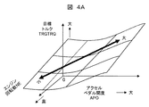
図4A、図4B、図4Cはアクセルペダル開度と内燃機関の回転数に対する目標トルクの特性、目標トルクに対する目標圧縮比の特性、及び目標圧縮比に対する目標制御値(ここでは、目標吸気弁閉時期とピストンの目標ストローク)の特性を示す特性図である。 4A, 4B and 4C show the characteristics of the target torque with respect to the accelerator pedal opening degree and the rotational speed of the internal combustion engine, the characteristics of the target compression ratio with respect to the target torque, and the target control value with respect to the target compression ratio (here, the target intake valve closing FIG. 6 is a characteristic diagram showing characteristics of timing and a target stroke of a piston.
図4AのZ軸は目標トルクTRGTRQを示し、X軸はアクセルペダル開度APOを示し、Y軸は内燃機関回転数NEを示しており、アクセルペダル開度APOと回転数NEに対する目標トルクTRGTRQの特性を示している。アクセルペダル開度APOの増加と回転数NEの増加に応じて目標トルクTRGTRQは増加する特性である。 The Z axis in FIG. 4A indicates the target torque TRGTRQ, the X axis indicates the accelerator pedal opening APO, and the Y axis indicates the internal combustion engine rotational speed NE. The accelerator pedal opening APO and the target torque TRGTRQ for the rotational speed NE It shows the characteristics. The target torque TRGTRQ is a characteristic that increases in accordance with the increase of the accelerator pedal opening APO and the increase of the rotational speed NE.
また、図4Bは目標圧縮比TRGCRと目標トルクTRGTRQの特性図を示しており、目標トルクTRGTRQが増加するのに伴い目標圧縮比TRGCRは小さくなる特性である。これにより目標トルクTRGTRQが小さい領域においてノッキングに対し点火時期の進角量の余力がある時、圧縮比を増加させることで熱効率の向上が得られ、かつ目標トルクTRGTRQが大きい領域においてノッキングに対し点火時期の余力が無い時、圧縮比を下げることで点火時期を進角させることができ熱効率の向上が得られる。 FIG. 4B shows a characteristic diagram of the target compression ratio TRGCR and the target torque TRGTRQ. The target compression ratio TRGCR decreases as the target torque TRGTRQ increases. As a result, when there is a surplus in the amount of advance of the ignition timing against knocking in the region where the target torque TRGTRQ is small, improvement in thermal efficiency can be obtained by increasing the compression ratio, and ignition is performed against knocking in the region where the target torque TRGTRQ is large. When there is no time surplus, the ignition timing can be advanced by lowering the compression ratio, and the thermal efficiency can be improved.
ここで目標圧縮比はこの特性に限るものではなく、一定、或いは増加させる特性とし、ノッキングに対し点火時期の余力を無くする方向に制御することで排気温度を上昇させ三元触媒の暖機運転を行うことで排気中のHC、CO等を抑制しても良い。 Here, the target compression ratio is not limited to this characteristic, and the characteristic is made constant or increased, and the exhaust temperature is raised by controlling in such a direction that there is no surplus of ignition timing against knocking, and the three-way catalyst warm-up operation The HC, CO, etc. in the exhaust may be suppressed by
図4Cの縦軸は目標吸気弁閉じ時期TRGIVCと目標ストロークTRGSTRを示し、横軸はこの特性図から得られた目標圧縮比TRGCRを示している。目標圧縮比TRGCRが大となる領域では、目標吸気弁閉じ時期TRGIVCを下死点(以下、BDC)方向へ変更、或いは目標ストロークTRGSTRを大きくする方向へ変更する特性とする。目標吸気弁閉じ時期TRGIVCをBDCへ近付けることで実圧縮比が増加する。また目標ストロークTRGSTRを大きくすることでピストン位置がクランクシャフト側から燃焼室側へ移動することになり機械圧縮比が増加する。目標吸気弁閉じ時期TRGIVCと目標ストロークTRGSTRを適宜位置へ変更することで機械圧縮比と実圧縮比を任意に増減できる。 The vertical axis in FIG. 4C indicates the target intake valve closing timing TRGIVC and the target stroke TRGSTR, and the horizontal axis indicates the target compression ratio TRGCR obtained from this characteristic chart. In a region where the target compression ratio TRGCR becomes large, the target intake valve closing timing TRGIVC is changed to a bottom dead center (hereinafter, BDC) direction or a target stroke TRGSTR is changed to a larger direction. By bringing the target intake valve closing timing TRGIVC closer to BDC, the actual compression ratio increases. Further, by increasing the target stroke TRGSTR, the piston position moves from the crankshaft side to the combustion chamber side, and the mechanical compression ratio increases. The mechanical compression ratio and the actual compression ratio can be arbitrarily increased or decreased by changing the target intake valve closing timing TRGIVC and the target stroke TRGSTR to appropriate positions.
また、本実施形態例では可変動弁、及びメインシャフトとサブシャフトの距離、あるいはコネクティングロッドの長さを可変とするストローク調整機構を備えるクランクシャフトを備える場合を示しているが、そのどちらか一方を備える内燃機関でも圧縮比を変更し燃焼室内圧力を可変とすることが可能である。 Further, in the present embodiment, the crankshaft is provided with a variable valve and a stroke adjustment mechanism which makes the distance between the main shaft and the subshaft or the length of the connecting rod variable, either one of them It is possible to change the compression ratio and make the pressure in the combustion chamber variable even in an internal combustion engine provided with
図5A、図5Bは目標トルクに対する目標吸入空気量と、目標吸入空気量に対する目標スロットル開度の特性を示す特性図を示している。 FIGS. 5A and 5B show characteristics of the target intake air amount with respect to the target torque and the target throttle opening degree with respect to the target intake air amount.
図5Aの縦軸は目標吸入空気量TRGAIRを示し、横軸はこの特性図から得られた目標トルクTRGTRQを示している。目標トルクTRGTRQが増大すると、目標吸入空気量TRGAIRを増大する特性を示している。 The vertical axis in FIG. 5A represents the target intake air amount TRGAIR, and the horizontal axis represents the target torque TRGTRQ obtained from this characteristic chart. The graph shows that the target intake air amount TRGAIR increases as the target torque TRGTRQ increases.
図5Bの目標スロットル開度TRGATVと目標吸入空気量TRGAIRの関係を示しており、目標吸入空気量TRGAIRの増大に伴い目標スロットル開度TRGATVは開き側へ制御する特性である。これより目標トルクTRGTRQの増大に伴う目標吸入空気量TRGAIRの増大に対し、目標スロットル開度TRGATVを開くことで吸気管内における絞りを低減でき、目標吸入空気量TRGAIRを満足できる。 The relationship between the target throttle opening degree TRGATV and the target intake air amount TRGAIR in FIG. 5B is shown, and the target throttle opening degree TRGATV is a characteristic controlled to the opening side with the increase of the target intake air amount TRGAIR. From this, it is possible to reduce the throttle in the intake pipe by opening the target throttle opening degree TRGATV with respect to the increase of the target intake air amount TRGAIR accompanying the increase of the target torque TRGTRQ, and the target intake air amount TRGAIR can be satisfied.
図6A、図6Bは目標トルクと回転数に対する目標空燃比と、目標空燃比と目標吸入空気量に対する目標噴射量の特性を示す特性図を示している。 6A and 6B show characteristics of the target air-fuel ratio with respect to the target torque and the rotational speed, and the characteristics of the target injection amount with respect to the target air-fuel ratio and the target intake air amount.
図6Aの縦軸は目標トルクTRGTRQであり、横軸は回転数NEであり、目標トルクTRGTRQと回転数NEに対する目標空燃比TRGAFの特性を示している。目標トルクTRGTRQの増大に伴い目標空燃比TRGAFはリーンとなる特性である。ここで、目標空燃比TRGAFの特性図はこの例に限るものではなく、全域をストイキ、或いはリーンとしても良い。 The vertical axis in FIG. 6A is the target torque TRGTRQ, and the horizontal axis is the rotational speed NE, showing the characteristics of the target air-fuel ratio TRGAF with respect to the target torque TRGTRQ and the rotational speed NE. The target air-fuel ratio TRGAF becomes lean as the target torque TRGTRQ increases. Here, the characteristic diagram of the target air-fuel ratio TRGAF is not limited to this example, and the entire region may be stoichiometric or lean.
図6Bは目標空燃比TRGAFと目標吸入空気量TRGAIRに基づく目標噴射量TRGQFの特性を示している。目標空燃比TRGAFのストイキ化と目標吸入空気量TRGAIRの増大に応じて目標噴射量TRGQFは増大する特性である。 FIG. 6B shows the characteristic of the target injection amount TRGQF based on the target air-fuel ratio TRGAF and the target intake air amount TRGAIR. The target injection amount TRGQF increases as the target air-fuel ratio TRGAF is made stoichiometric and the target intake air amount TRGAIR increases.
図7A、図7Bは目標トルクと回転数に対する目標EGR量と、目標EGR量に対する目標EGR弁開度の特性を示す特性図である。 FIGS. 7A and 7B are characteristic diagrams showing characteristics of the target EGR amount with respect to the target torque and the rotational speed, and the target EGR valve opening degree with respect to the target EGR amount.
図7Aの縦軸は目標トルクTRGTRQであり、横軸は回転数NEであり、目標トルクTRGTRQと回転数NEに対する目標EGR量TRGEGRの特性を示している。目標トルクTRGTRQの増減に伴い、目標EGR量TRGEGRは多い領域と少ない領域となる特性である。ここで、目標EGR量TRGEGRの特性図はこの例に限るものではなく、全域を一定値、或いは目標トルクTRGTRQの増大に応じて単調増加としても良いものである。 The vertical axis in FIG. 7A is the target torque TRGTRQ, and the horizontal axis is the rotational speed NE, which shows the characteristics of the target EGR amount TRGEGR with respect to the target torque TRGTRQ and the rotational speed NE. The target EGR amount TRGEGR is a characteristic that becomes a large area and a small area with increase and decrease of the target torque TRGTRQ. Here, the characteristic diagram of the target EGR amount TRGEGR is not limited to this example, and the entire region may be a constant value or may be monotonically increased according to the increase of the target torque TRGTRQ.
図7Bは目標EGR弁開度TRGETVに基づく目標EGR量TRGEGRとの特性を示している。目標EGR量TRGEGRの増加に伴い、目標EGR弁開度TRGETVを開き方向へ制御する特性である。 FIG. 7B shows characteristics of the target EGR amount TRGEGR based on the target EGR valve opening degree TRGETV. The target EGR valve opening degree TRGETV is controlled in the opening direction with an increase in the target EGR amount TRGEGR.
図8は目標トルクTRGTRQと回転数NEに対する目標点火時期TRGIGNの特性を示す特性図である。 FIG. 8 is a characteristic diagram showing the characteristics of the target ignition timing TRGIGN with respect to the target torque TRGTRQ and the rotational speed NE.
図8の縦軸は目標トルクTRGTRQであり、横軸は回転数NEであり、目標トルクTRGTRQと回転数NEに対する目標点火時期TRGIGNの特性を示している。目標トルクTRGTRQの増大に伴い、目標点火時期TRGIGNは遅角する特性である。また回転数NEの高回転化に伴い目標点火時期TRGIGNは進角する特性である。ここで、目標点火時期TRGIGNの特性図はこの例に限るものではなく、全域を一定値、或いは目標トルクTRGTRQの増大に応じて進角する特性としても良いものである。 The vertical axis in FIG. 8 is the target torque TRGTRQ, and the horizontal axis is the rotational speed NE, showing the characteristics of the target ignition timing TRGIGN with respect to the target torque TRGTRQ and the rotational speed NE. The target ignition timing TRGIGN is a characteristic that is retarded as the target torque TRGTRQ increases. Further, the target ignition timing TRGIGN is a characteristic that advances as the rotational speed NE increases. Here, the characteristic diagram of the target ignition timing TRGIGN is not limited to this example, and the entire region may be a constant value or may be a characteristic that advances as the target torque TRGTRQ increases.
このように、本実施形態になる内燃機関システムでは、圧縮比を可変とする可変圧縮比制御、或いは異常燃焼を抑制する排気循環燃焼制御、或いはリーン燃焼制御が単独で適用されるか、好ましくは、本実施形態のようにこれらが組み合わせられて適用されている。 As described above, in the internal combustion engine system according to the present embodiment, variable compression ratio control that makes the compression ratio variable, or exhaust circulation combustion control that suppresses abnormal combustion, or lean combustion control is applied alone, preferably, These are combined and applied as in the present embodiment.
ところで、本発明者等の検討によると、少なくとも可変圧縮比、排気循環燃焼、リーン燃焼等のいずれかを行う内燃機関においては、燃焼室内の混合気の状態が内燃機関の出力に応じて大きく変化するため、点火装置による点火不良が生じて失火現象が発生することが新たに判明した。 By the way, according to the study of the present inventors, in an internal combustion engine that performs at least one of variable compression ratio, exhaust circulation combustion, lean combustion, etc., the state of air-fuel mixture in the combustion chamber largely changes according to the output of the internal combustion engine Therefore, it has been newly found that a misfire phenomenon occurs due to ignition failure due to the igniter.
つまり、圧縮比の増加、排気循環量の増加、リーン空燃比の増加により圧縮行程での燃焼室内圧力が増加し、この燃焼室内圧力の増加に応じて、点火プラグにおける絶縁破壊電圧と放電電圧が増加するようになり、点火装置内の蓄電エネルギーが低燃焼室圧力時に比べ早く消費されることで放電時間が短縮され、火炎核の成長が不足することで失火に至るものである。したがって、この失火現象を抑制して排気浄化性能を向上することが強く要請されている。 That is, the pressure in the combustion chamber in the compression stroke increases due to the increase of the compression ratio, the increase of the exhaust circulation amount, and the increase of the lean air fuel ratio, and the dielectric breakdown voltage and the discharge voltage at the spark plug The discharge time is shortened because the stored energy in the igniter is consumed more quickly than at the low combustion chamber pressure, and the misfire is caused by the lack of growth of the flame kernel. Therefore, there is a strong demand to suppress the misfire phenomenon to improve the exhaust purification performance.
そこで、本実施形態ではこの要請に応えるため、1サイクル中の点火装置による1回の点火動作において、点火装置への点火信号の通電を断続的に行い、しかも内燃機関の燃焼室内圧力に応じて通電回数を増減する制御を行なう構成を提案するものである。尚、通電の断続間隔は、点火プラグによる放電が継続できる間隔に設定されることはいうまでもない。 Therefore, in the present embodiment, in order to meet this requirement, in one ignition operation by the igniter in one cycle, energization of the ignition signal to the igniter is performed intermittently, and in accordance with the pressure in the combustion chamber of the internal combustion engine. A configuration is proposed in which control is performed to increase or decrease the number of times of energization. It is needless to say that the intermittent intervals of energization are set to intervals at which discharge by the spark plug can be continued.
これによれば、点火信号の通電を断続することによって点火エネルギーが瞬間的に立ち上がるブレークダウンが生じ、燃焼室の圧力に応じてこの通電回数(即ち、ブレークダウンの回数)を制御(増減)すれば、燃焼室内圧力が増加しても放電時間が長くなって混合気への着火を確実に実行でき、失火現象の発生を抑制することができるようになる。その結果、燃費性能と排気性能を向上することができる。 According to this, a breakdown occurs in which the ignition energy instantaneously rises due to intermittent application of the ignition signal, and the number of times of energization (that is, the number of breakdowns) is controlled (increased or decreased) according to the pressure of the combustion chamber. For example, even if the pressure in the combustion chamber increases, the discharge time becomes long, and the mixture can be reliably ignited, so that the occurrence of the misfire phenomenon can be suppressed. As a result, fuel efficiency and exhaust performance can be improved.
以下、本実施形態の詳細について説明する。図9は本実施形態による点火信号の通電回数算出ロジック図である。 Hereinafter, the details of the present embodiment will be described. FIG. 9 is a logic diagram for calculating the number of times the ignition signal is energized according to the present embodiment.
図9において、クランク角度CAと、目標点火時期TRGIGNと、燃焼室内圧力Pは通電回数演算部TIGNTに入力される。また、イオン電流センサ信号IONと、吸入空気量QAと、空燃比AFと、目標EGR量TRGEGRは燃焼室内圧力推定部TPESに入力され、推定燃焼室内圧力P*を演算して通電回数演算部TIGNTに入力される。ここで、燃焼室圧力センサを使用して燃焼室内圧力Pを直接検出して使用する方法と、推定燃焼室内圧力P*を推定して使用する方法があるが、どちらか一方を使用して燃焼室圧力を求めればよいものである。 In FIG. 9, the crank angle CA, the target ignition timing TRGIGN, and the pressure P in the combustion chamber are input to the number-of-times-of-energization calculation unit TIGNT. The ion current sensor signal ION, the intake air amount QA, the air-fuel ratio AF, and the target EGR amount TRGEGR are input to the combustion chamber pressure estimation unit TPES, and the estimated combustion chamber pressure P * is calculated to calculate the number of times of energization operation unit TIGNT Is input to Here, there are a method of directly detecting and using the pressure P in the combustion chamber using a combustion chamber pressure sensor, and a method of estimating and using the estimated pressure P * in the combustion chamber, but either one is used for combustion. It is sufficient to determine the chamber pressure.
ただ、燃焼室圧力センサの故障検知や出力異常検知を行う場合は、両方の方法で燃焼室内圧力を求め、推定燃焼圧P*を用いて燃焼室圧力センサの検出圧力を検証することで燃焼室圧力センサの故障や異常を判断することができる。 However, when performing failure detection or output abnormality detection of the combustion chamber pressure sensor, the combustion chamber pressure is obtained by both methods, and the combustion chamber pressure sensor P * is used to verify the detected pressure of the combustion chamber pressure sensor. Failure or abnormality of the pressure sensor can be determined.
上述した入力値を用いて通電回数演算部TIGNTでは通電回数Npを演算して出力する。ここで、通電回数演算部TIGNTは、1回の点火動作に複数回の点火信号の通電を行う制御装置と共に用いられる。通電回数演算部TIGNTの通電回数Npは通電を指令する点火制御を行う制御装置で用いられ、点火装置の点火時期、つまり目標点火時期TRGIGNにおいて、燃焼室内圧力に応じて1回の点火動作における点火信号の通電回数を設定するように多段通電制御を指令する制御装置となる。 The energization number calculation unit TIGNT calculates and outputs the energization number Np using the above-described input value. Here, the number-of-energization computation unit TIGNT is used together with a control device that energizes a plurality of ignition signals for one ignition operation. The energization number Np of the energization number calculation unit TIGNT is used in a control device that performs ignition control to command energization, and ignition is performed in one ignition operation according to the pressure in the combustion chamber at the ignition timing of the ignition device, that is, at the target ignition timing TRGIGN. It becomes a control device which commands multi-stage energization control to set the number of times of signal energization.
これにより、燃焼室内圧力の変化に伴う点火プラグにおける絶縁破壊電圧と放電電圧の変化に伴う点火コイルの蓄電エネルギー要求量の変化に対応し、放電時間を最適に制御(増減)することができ、必要最小限の蓄電エネルギーを供給するようにできる。これによって必要最小限の蓄電エネルギーとすることにより、内燃機関システムの省エネルギー化と、燃焼室内の混合気が要求する蓄電エネルギーを過不足なく供給することができる。もちろん放電時間を充分確保できるので、失火現象を抑制して燃焼の高効率化を実現でき、更に燃費性能と排気性能の改善効果が得られるようになる。 Thus, the discharge time can be optimally controlled (increased or decreased) in response to the change in the storage energy requirement of the ignition coil due to the change in the dielectric breakdown voltage and the discharge voltage in the ignition plug due to the change in pressure in the combustion chamber. It is possible to supply the minimum necessary storage energy. By setting the storage energy to the minimum necessary by this, energy saving of the internal combustion engine system and storage energy required by the mixture in the combustion chamber can be supplied without excess or deficiency. Of course, since the discharge time can be sufficiently secured, the misfire phenomenon can be suppressed to realize the high efficiency of the combustion, and further, the improvement effect of the fuel efficiency and the exhaust performance can be obtained.
本実施例では好ましくは、燃焼室内圧力を検出する手段、或いは燃焼室内圧力を推定する手段を有している。燃焼室内圧力を検出する手段は、燃焼室内圧力を直接検出する圧力センサであり、これによって燃焼室内圧力Pを直接的に検出することができる。 In this embodiment, preferably, means for detecting the pressure in the combustion chamber or means for estimating the pressure in the combustion chamber is provided. The means for detecting the pressure in the combustion chamber is a pressure sensor for directly detecting the pressure in the combustion chamber, whereby the pressure P in the combustion chamber can be directly detected.
また、燃焼室内圧力を推定する手段は、燃焼室内圧力推定部TPESであり、(1)イオン電流センサのイオン電流信号IONと、空燃比センサの信号AFと、目標EGR量TRGEGRを用いて燃焼室内圧力を推定することができ、或いは(2)吸入空気量センサの信号QAと空燃比センサの信号AFと目標EGR量TRGEGRを用いて燃焼室内圧力を推定することができる。 Further, the means for estimating the pressure in the combustion chamber is the combustion chamber pressure estimation unit TPES, and (1) the combustion chamber using the ion current signal ION of the ion current sensor, the signal AF of the air-fuel ratio sensor, and the target EGR amount TRGEGR The pressure can be estimated, or (2) the pressure in the combustion chamber can be estimated using the signal QA of the intake air amount sensor, the signal AF of the air-fuel ratio sensor, and the target EGR amount TRGEGR.
上記した燃焼室内圧力を検出する手段、或いは燃焼室内圧力を推定する手段によって、各気筒の点火時期付近(点火前、或いは点火後)における燃焼室内圧力を検出、或いは推定し、この検出、或いは推定された燃焼室内圧力は、通電回数演算部TIGNTに入力されて通電回数Npが演算されて出力される。 The means for detecting the pressure in the combustion chamber described above or means for estimating the pressure in the combustion chamber detects or estimates the pressure in the combustion chamber in the vicinity of the ignition timing of each cylinder (before or after ignition) The pressure in the combustion chamber is input to the energization number calculation unit TIGNT, and the number of energization Np is calculated and output.
具体的には、本実施例では燃焼室内圧力Pを検出する圧力センサが備えられており、燃焼室内圧力Pが通電回数演算部TIGNTに入力される場合、クランク角度CAと目標点火時期TRGIGNの同期をもって燃焼室内圧力Pを検出し、燃焼室内圧力Pに応じて通電回数演算部TIGNTでは通電回数Npを演算、出力するように構成することができる。 Specifically, in the present embodiment, a pressure sensor for detecting the pressure P in the combustion chamber is provided, and when the pressure P in the combustion chamber is input to the number of times of operation calculation unit TIGNT, synchronization of the crank angle CA and the target ignition timing TRGIGN The pressure P in the combustion chamber can be detected in accordance with the pressure P in the combustion chamber, and the number of times of energization Np can be calculated and output in the number-of-times-of-electricity calculation unit TIGNT.
一方、燃焼室内圧力Pを検出する圧力センサが備えられておらず、燃焼室内圧力Pが通電回数演算部TIGNTに入力されない場合は、次のような方法で通電回数Npが求められる。 On the other hand, when the pressure sensor for detecting the pressure P in the combustion chamber is not provided and the pressure P in the combustion chamber is not input to the number-of-times calculator TIGNT, the number Np of times of energization can be obtained by the following method.
第1には、イオン電流信号IONを検出するイオン電流センサが備えられている場合では、イオン電流信号IONと、空燃比AFと、目標EGR量TRGEGRが燃焼室内圧力推定部TPESに入力され、イオン電流信号IONと、空燃比AFと、目標EGR量TRGEGRを用いて所定の演算、或いは物理モデルを利用して燃焼室内圧力推定量P*を推定し、推定された燃焼室内圧力P*に応じて通電回数演算部TIGNTでは通電回数Npを演算、出力するように構成することができる。 First, when the ion current sensor for detecting the ion current signal ION is provided, the ion current signal ION, the air-fuel ratio AF, and the target EGR amount TRGEGR are input to the combustion chamber pressure estimation unit TPES, and the ion According to the estimated pressure P * in the combustion chamber, the estimated pressure P * in the combustion chamber is estimated using the current signal ION, the air-fuel ratio AF, and the target EGR amount TRGEGR using a predetermined calculation or physical model. The energization number calculation unit TIGNT can be configured to calculate and output the number of energization times Np.
第2には、圧力センサやイオン電流センサが備えられていない場合、吸入空気量QAと、空燃比AFと、目標EGR量TRGEGRが燃焼室内圧力推定部TPESに入力され、吸入空気量QAと、空燃比AFと、目標EGR量TRGEGRを用いて所定の演算、或いは物理モデルを利用して燃焼室内圧力推定量P*を推定し、推定された燃焼室内圧力P*に応じて通電回数演算部TIGNTでは通電回数Npを演算、出力するように構成することができる。 Second, when no pressure sensor or ion current sensor is provided, the intake air amount QA, the air-fuel ratio AF, and the target EGR amount TRGEGR are input to the combustion chamber pressure estimation unit TPES, and the intake air amount QA, The estimated pressure P * in the combustion chamber is estimated using the air-fuel ratio AF and the target EGR amount TRGEGR using a predetermined calculation or physical model, and the number-of-times-of-current operation unit TIGNT according to the estimated pressure P * in the combustion chamber. In this case, the number of times of energization Np can be calculated and output.
このように、燃焼室内圧力を検出する手段、或いは燃焼室内圧力を推定する手段によって燃焼室内圧力の変化を精確に、かつリアルタイムに検出、或いは推定可能となり、通電回数Npの最適化が可能となる。その結果、燃費性能と排気性能の改善効果が最大化できる。尚、通電回数演算部TIGNTによる通電回数Npの演算については後述する。 As described above, the means for detecting the pressure in the combustion chamber or the means for estimating the pressure in the combustion chamber can accurately detect the change in the pressure in the combustion chamber in real time, or can estimate it in real time, and the number of times of energization Np can be optimized. . As a result, the improvement effect of fuel consumption performance and exhaust performance can be maximized. The calculation of the number of times of energization Np by the number of times of energization calculation unit TIGNT will be described later.
本実施例になる内燃機関の制御装置は、内燃機関出力が同一条件においても燃焼室内圧力Pを可変とすることが可能な可変圧縮比機構を備える可変圧縮比内燃機関に適用することが特に望ましい。なぜならば、吸入空気量と空燃比とEGR量が同一であっても実圧縮比、或いは機械圧縮比を可変調整する場合において、当然のことながら燃焼室内圧力が変化するためである。 It is particularly desirable that the control device for an internal combustion engine according to this embodiment be applied to a variable compression ratio internal combustion engine provided with a variable compression ratio mechanism capable of making the pressure P in the combustion chamber variable even under the same conditions. . This is because the pressure in the combustion chamber naturally changes when the actual compression ratio or the mechanical compression ratio is variably adjusted even if the intake air amount, the air fuel ratio, and the EGR amount are the same.
可変圧縮比内燃機関においては、点火装置による点火時期における燃焼室内圧力に応じて点火信号の通電回数を設定することで、必要最小限の蓄電エネルギーとすることによる内燃機関システムの省エネルギー化と、燃焼室内の混合気が要求する蓄電エネルギーを過不足なく供給することによる燃焼の高効率化を実現でき、燃費性能と排気性能の改善効果が最大化する。 In the variable compression ratio internal combustion engine, energy saving of the internal combustion engine system by setting the number of times of energization of the ignition signal according to the pressure in the combustion chamber at the ignition timing by the igniter High efficiency of combustion can be realized by supplying storage energy required by the mixture in the room without excess and deficiency, and the improvement effect of fuel efficiency and exhaust performance is maximized.
また、燃焼室内圧力を可変調整する可変圧縮比機構は、吸気弁の閉じ時期、或いはピストンのストローク量の変更により可変とする機構であり、吸気弁の閉じ時期、或いはピストンのストローク量の指令値は、図4Cの特性図に基づき与えられる。したがって、可変圧縮比内燃機関の圧縮比制御と、1回の点火動作に複数回の点火信号の通電が行なわれる点火装置と、燃焼室内圧力に応じた点火信号の通電回数の設定を行う制御装置を組み合わせて使用することで、適切な制御システムに統合することが可能となる。 The variable compression ratio mechanism that variably adjusts the pressure in the combustion chamber is a mechanism that makes it variable by changing the closing timing of the intake valve or the stroke amount of the piston, and indicates the closing timing of the intake valve or the command value of the stroke amount of the piston Is given based on the characteristic diagram of FIG. 4C. Therefore, a compression ratio control of the variable compression ratio internal combustion engine, an ignition device in which ignition signals are energized a plurality of times in one ignition operation, and a control device which sets the number of times of ignition signals in accordance with the pressure in the combustion chamber. Can be integrated into an appropriate control system.
次に、燃焼室内圧力の圧力センサによる検出方法と、燃焼室内圧力推定部TPESによる推定方法による通電回数Npの求め方の具体的な例について、図10A、図10B、図11A〜図11C、図12A〜図12Cを用いて説明する。 Next, a specific example of how to detect the pressure in the combustion chamber with a pressure sensor and how to determine the number of times of energization Np by the estimation method using the combustion chamber pressure estimation unit TPES will be described with reference to FIGS. 10A, 10B, 11A to 11C, This will be described using 12A to 12C.
図10A、図10Bは燃焼室内圧力センサを用いた点火時期圧力に基づく通電回数Npの特性を示す特性図である。 FIGS. 10A and 10B are characteristic diagrams showing the characteristics of the number of times of energization Np based on the ignition timing pressure using the pressure sensor in the combustion chamber.
図10Aにおいて、縦軸は燃焼室内圧力Pを示し、横軸はクランク角度CAを示している。正常に燃焼が行われた際には、上死点TDC以降に燃焼室内圧力は最大値を示すことになる。また、目標点火時期TRGIGNは上死点TDC以前に設定されている。目標点火時期TRGIGNの直前における燃焼室内圧力Pを点火時期圧力PIGNにとして検出する。この場合、点火時期圧力PIGNは目標点火時期TRGIGNに近い時点の圧力である方が望ましい。検出された点火時期圧力PIGNは通電回数演算部TIGNTに入力されて通電回数Npが設定される。 In FIG. 10A, the vertical axis represents the pressure P in the combustion chamber, and the horizontal axis represents the crank angle CA. When combustion is normally performed, the pressure in the combustion chamber exhibits the maximum value after the top dead center TDC. Further, the target ignition timing TRGIGN is set before the top dead center TDC. The combustion chamber pressure P immediately before the target ignition timing TRGIGN is detected as an ignition timing pressure PIGN. In this case, it is desirable that the ignition timing pressure PIGN be a pressure close to the target ignition timing TRGIGN. The detected ignition timing pressure PIGN is input to the energization number calculation unit TIGNT, and the number of energizations Np is set.
図10Bにおいて、縦軸は通電回数Npを示し、横軸は点火時期圧力PIGNを示している。点火時期圧力PIGNが増大するのに伴い、通電回数Npは多く設定される特性である。これにより、通電回数Npが増加することで1行程中の点火装置(=点火コイル)に蓄電されるエネルギーが増加し、かつ点火プラグから燃焼室内の混合気へとエネルギーが伝わる伝達効率が高い絶縁破壊現象を複数回与えることができるため、放電時間が長くなって火炎核の成長が促進され、失火の発生を抑制できるようになる。 In FIG. 10B, the vertical axis represents the number of times of energization Np, and the horizontal axis represents the ignition timing pressure PIGN. As the ignition timing pressure PIGN increases, the number of times of energization Np is a characteristic that is set larger. As a result, the energy stored in the igniter (= ignition coil) in one stroke increases due to the increase in the number of times of energization Np, and the transmission efficiency of energy transfer from the spark plug to the mixture in the combustion chamber is high. Since the destruction phenomenon can be given a plurality of times, the discharge time is lengthened, the growth of flame kernels is promoted, and the occurrence of misfire can be suppressed.
また、正常に燃焼が行われない時、つまり目標点火時期TRGIGNの前に燃焼室内圧力Pが任意の閾値以上となった場合においては、通電回数Npを所定の一定回数に制限、或いは減少させても良いものである。これは燃焼室内圧力Pが任意の閾値以上である時、燃焼室内では点火時期前に燃焼が開始してしまう過早着火と呼ばれる現象が発生している場合であり、過早着火後の燃焼室内圧力値は非常に高い値を示すからである。過早着火が生じると内燃機関の破損を招くため、可能な限り燃焼反応を抑制する必要がある。このため、通電回数Npは所定の一定回数に制限、或いは減少させることで、混合気へ伝達されるエネルギーを低減させることは有効である。 Further, when combustion is not normally performed, that is, when the pressure P in the combustion chamber becomes an arbitrary threshold or more before the target ignition timing TRGIGN, the number of times of energization Np is limited or reduced to a predetermined fixed number of times. Is also good. This is a case where a phenomenon called "pre-ignition" occurs in which combustion starts before the ignition timing in the combustion chamber when the pressure P in the combustion chamber is equal to or higher than an arbitrary threshold value. This is because the pressure value is very high. Since pre-ignition causes breakage of the internal combustion engine, it is necessary to suppress the combustion reaction as much as possible. For this reason, it is effective to reduce the energy transmitted to the air-fuel mixture by limiting or decreasing the number of times of energization Np to a predetermined fixed number of times.
図11A〜図11Cは本実施形態によるイオン電流センサを用いた燃焼室内圧力推定量P*(I)に基づく通電回数Npの特性を示す特性図である。尚、イオン電流センサを用いる場合は燃焼後の燃焼室内圧力推定量P*(I)を用いるので、通電回数Npが反映されるのは次の行程の点火時期である。 11A to 11C are characteristic diagrams showing the characteristics of the number of times of energization Np based on the estimated pressure P * (I) in the combustion chamber using the ion current sensor according to the present embodiment. In the case of using the ion current sensor, since the estimated pressure P * (I) in the combustion chamber after combustion is used, the number of times of energization Np is reflected in the ignition timing of the next stroke.
図11Aにおいて、縦軸はイオン電流信号IONを示し、横軸はクランク角度CAを示している。正常に燃焼が行われた際には、上死点TDC以降にイオン電流信号IONは2つ、或いは3つの山形状の信号が現れる。ここでは2つの山形状のイオン電流信号IONが得られる場合の方法について述べる。イオン電流信号IONは上死点TDC前、上死点TDC後の2つの山形状の信号が現れる。ここで2つ目の山形状のイオン電流信号IONの最大値をイオン電流ピークIMAXとして検出する。 In FIG. 11A, the vertical axis represents the ion current signal ION, and the horizontal axis represents the crank angle CA. When combustion is normally performed, two or three mountain-shaped signals appear in the ion current signal ION after the top dead center TDC. Here, a method will be described in the case where two mountain-shaped ion current signals ION can be obtained. In the ion current signal ION, two peak-shaped signals appear before the top dead center TDC and after the top dead center TDC. Here, the maximum value of the second mountain-shaped ion current signal ION is detected as the ion current peak IMAX.
図11Bにおいて、縦軸は燃焼室内圧力推定量P*(I)を示し、横軸はイオン電流ピークIMAXを示している。ここで、燃焼室内圧力推定量P*(I)はイオン電流ピークIMAXの検出時期ではなく、目標点火時期TRGIGNにおける燃焼室内圧力P*(I)の推定値である。この推定値はイオン電流ピークIMAXをパラメータとした演算や物理モデルから求めることができる。 In FIG. 11B, the vertical axis represents the estimated pressure P * (I) in the combustion chamber, and the horizontal axis represents the ion current peak IMAX. Here, the estimated amount of pressure in the combustion chamber P * (I) is not the detection timing of the ion current peak IMAX but an estimated value of the pressure in the combustion chamber P * (I) at the target ignition timing TRGIGN. This estimated value can be obtained from an operation or physical model using the ion current peak IMAX as a parameter.
空燃比AFがストイキ、かつ目標EGR量が0である時、イオン電流ピークIMAXの増加に伴い燃焼室内圧力推定量P*(I)は増加する傾向を示すようになる。なぜなら、イオン電流ピークIMAXの増加は燃焼室内の燃焼温度の上昇と相関があるためである。 When the air-fuel ratio AF is stoichiometric and the target EGR amount is 0, the estimated pressure P * (I) in the combustion chamber tends to increase as the ion current peak IMAX increases. The reason is that the increase of the ion current peak IMAX is correlated with the increase of the combustion temperature in the combustion chamber.
また、空燃比AFがリーンに変化する、或いは目標EGR量TRGEGRが多くなる場合においては、イオン電流ピークIMAXの増加に伴う燃焼室内圧力推定量P*(I)の増加傾向は同一であるものの、その勾配が大きくなる。一例として空燃比AFがリーンに変化した時の勾配は、空燃比AFがストイキの時の勾配より大きい。 When the air-fuel ratio AF changes to lean or the target EGR amount TRGEGR increases, the increasing tendency of the estimated pressure P * (I) in the combustion chamber with the increase of the ion current peak IMAX is the same. The gradient becomes large. As one example, the slope when the air-fuel ratio AF changes to lean is larger than the slope when the air-fuel ratio AF is stoichiometric.
また、空燃比AFがリーンであり目標EGR量TRGEGRが多くなる時の勾配は、空燃比AFがリーン、かつ目標EGR量TRGEGRが0の時の勾配よりは大きい。なぜなら、空燃比がリーンになる時、或いはEGR量が増加するときには目標点火時期における混合気量が増加しており、燃焼室内圧力Pが高まるのに対してリーン、或いはEGR量増加は断熱火炎温度が低下するために燃焼温度が低下し、イオン発生量が減少するためである。 Further, the slope when the air-fuel ratio AF is lean and the target EGR amount TRGEGR increases is larger than the slope when the air-fuel ratio AF is lean and the target EGR amount TRGEGR is zero. This is because when the air-fuel ratio becomes lean or when the EGR amount increases, the mixture amount at the target ignition timing increases, and while the pressure P in the combustion chamber increases, the lean or EGR amount increase indicates the adiabatic flame temperature. As a result, the combustion temperature decreases and the amount of generated ions decreases.
図11Cにおいて、縦軸に通電回数Npを示し、横軸には燃焼室内圧力推定量P*(I)を示している。燃焼室内圧力推定量P*(I)が増大するのに伴い、通電回数Npは多く設定される特性である。これにより、通電回数Npが増加することで1回の点火動作での点火コイルに蓄電されるエネルギーが増加し、かつ点火プラグから燃焼室内の混合気へとエネルギーが伝わる伝達効率が高い絶縁破壊現象を複数回与えることができるため、放電時間が長くなって火炎核の成長が促進され、失火の発生を抑制できる。 In FIG. 11C, the vertical axis represents the number of times of energization Np, and the horizontal axis represents the estimated pressure P * (I) in the combustion chamber. The number of times of energization Np is a characteristic that is set to be large as the estimated pressure P * (I) in the combustion chamber increases. As a result, the energy stored in the ignition coil in one ignition operation increases as the number of times of energization Np increases, and a dielectric breakdown phenomenon in which the energy is transmitted from the spark plug to the mixture in the combustion chamber is high. Can be given multiple times, so the discharge time becomes longer and the growth of flame kernels is promoted, and the occurrence of misfire can be suppressed.
また、正常に燃焼が行われない時、つまり上述した2つのイオン電流信号に先行して3つ目の山形状のイオン電流信号IONが検出される。3つ目の山形状信号のピーク値が任意の閾値以上となった場合においては、通電回数Npを所定の一定回数に制限、或いは減少させても良いものである。尚、3つ目の山形状の信号は目標点火時期TRGIGNより以前に出現する。これは3つ目の山形状信号のピーク値が任意の閾値以上である時、燃焼室内では点火時期前に燃焼が開始してしまう過早着火と呼ばれる現象が発生している場合であり、過早着火後の燃焼室反応は目標点火時期TRGIGN以前に進行し3つ目の山形状のイオン電流信号IONが増加するためである。過早着火が生じると内燃機関の破損を招くため、可能な限り燃焼反応を抑制する必要がある。このため、通電回数Npは所定の一定回数に制限、或いは減少させることで、混合気へ伝達されるエネルギーを低減させることは有効である。 In addition, when combustion is not normally performed, that is, the third mountain-shaped ion current signal ION is detected prior to the two ion current signals described above. In the case where the peak value of the third mountain-shaped signal becomes equal to or greater than an arbitrary threshold value, the number of times of energization Np may be limited or reduced to a predetermined fixed number of times. The third peak signal appears before the target ignition timing TRGIGN. This is a case where a phenomenon called pre-ignition in which combustion starts before the ignition timing occurs in the combustion chamber when the peak value of the third mountain shape signal is equal to or higher than an arbitrary threshold value. The combustion chamber reaction after pre-ignition proceeds before the target ignition timing TRGIGN, and the ion current signal ION of the third peak shape increases. Since pre-ignition causes breakage of the internal combustion engine, it is necessary to suppress the combustion reaction as much as possible. For this reason, it is effective to reduce the energy transmitted to the air-fuel mixture by limiting or decreasing the number of times of energization Np to a predetermined fixed number of times.
図12A〜図12Cは本実施形態による吸入空気量QAと、空燃比AFと、目標EGR量TRGEGRを用いた燃焼室内圧力推定量P*(AE)に基づく通電回数の特性を示す特性図である。尚、吸入空気量QAと、空燃比AFと、目標EGR量TRGEGRを用いる場合は燃焼後の燃焼室内圧力推定量P*(AE)を用いるので、通電回数Npが反映されるのは次の行程の点火時期である。 12A to 12C are characteristic diagrams showing the characteristics of the number of times of energization based on the intake air amount QA according to the present embodiment, the air-fuel ratio AF, and the combustion chamber pressure estimated amount P * (AE) using the target EGR amount TRGEGR. . When the intake air amount QA, the air-fuel ratio AF, and the target EGR amount TRGEGR are used, the estimated pressure P * (AE) in the combustion chamber after combustion is used, so the number of times of energization Np is reflected in the next stroke Ignition timing.
図12Aにおいて、縦軸は吸入空気量QAを示し、横軸は空燃比AFを示している。吸入空気量QAの増加と空燃比AFのリーン化は、混合気量を増加すると共に目標点火時期TRGIGNにおける燃焼室内圧力推定量P*(A)を高める。 In FIG. 12A, the vertical axis represents the intake air amount QA, and the horizontal axis represents the air-fuel ratio AF. The increase in the intake air amount QA and the leanening of the air-fuel ratio AF both increase the mixture amount and increase the estimated pressure P * (A) in the combustion chamber at the target ignition timing TRGIGN.
図12Bにおいて、縦軸は燃焼室内圧力推定量P*(AE)を示し、横軸は目標EGR量TRGEGRを示している。目標EGR量TRGEGRの増加に伴い燃焼室内圧力推定量P*(AE)は高まる特性である。目標EGR量TRGEGRが0であるとき、燃焼室内圧力推定量P*(AE)は燃焼室内圧力推定量P*(A)となる。 In FIG. 12B, the vertical axis represents the estimated amount of pressure in the combustion chamber P * (AE), and the horizontal axis represents the target EGR amount TRGEGR. The estimated amount of pressure P * (AE) in the combustion chamber increases with the increase of the target EGR amount TRGEGR. When the target EGR amount TRGEGR is 0, the estimated amount of pressure in the combustion chamber P * (AE) becomes the estimated amount of pressure in the combustion chamber P * (A).
図12Cにおいて、縦軸は通電回数Npを示し、横軸は燃焼室内圧力推定量P*(AE)を示している。燃焼室内圧力推定量P*(AE)の高まりに応じて通電回数Npは多く設定される特性とする。これにより燃焼室内圧力に応じた通電回数Npの設定が、燃焼室内に露出した圧力センサやイオン電流センサを備えなくても実施できるようになる。 In FIG. 12C, the vertical axis represents the number of times of energization Np, and the horizontal axis represents the estimated pressure P * (AE) in the combustion chamber. It is assumed that the number of times of energization Np is set to a large value according to the increase of the estimated pressure P * (AE) in the combustion chamber. As a result, the setting of the number of times of energization Np according to the pressure in the combustion chamber can be performed without providing the pressure sensor and the ion current sensor exposed in the combustion chamber.
図13は本実施形態によるECU1で実行される制御内容を示すフローチャートである。このフローチャートでは、図3に示すピストンストローク、スロットル開度、燃料噴射量、EGR量、点火時期等の目標制御量を求める目標制御値算出ロジックと、図9に示す通電回数算出ロジックがECU1によって所定の周期で繰り返し実行されるものである。
FIG. 13 is a flowchart showing the contents of control executed by the
ステップS101において、アクセルペダル開度APO、内燃機関回転数NE、ECU1内のROMに書き込まれた各種制御値などを読み込む。次にステップS102において、内燃機関100に対する目標トルクTRGTRQを演算する。
In step S101, the accelerator pedal opening APO, the internal combustion engine rotational speed NE, various control values written in the ROM in the
ステップS103において、ステップS102の演算結果に基づき目標圧縮比TRGCR、目標吸入空気量TRGAIR、目標空燃比演算TRGAF、目標EGR量TRGEGR、目標点火時期TRGIGNを演算する。 In step S103, a target compression ratio TRGCR, a target intake air amount TRGAIR, a target air-fuel ratio calculation TRGAF, a target EGR amount TRGEGR, and a target ignition timing TRGIGN are calculated based on the calculation result of step S102.
次にステップS104において、ステップS103の演算結果に基づき、目標ストロークTRGSTR、目標スロットル開度TRGATV、目標噴射量TRGQF、目標EGR弁開度TRGETV、目標点火時期TRGIGNを演算する。 Next, in step S104, a target stroke TRGSTR, a target throttle opening degree TRGATV, a target injection amount TRGQF, a target EGR valve opening degree TRGETV, and a target ignition timing TRGIGN are calculated based on the calculation result of step S103.
次にステップS105において、クランク角度CA、目標点火時期TRGIGN、燃焼室内圧力P、イオン電流信号ION、吸入空気量QA、空燃比AF、目標EGR量TRGEGRを読み込む。 Next, at step S105, the crank angle CA, the target ignition timing TRGIGN, the combustion chamber pressure P, the ion current signal ION, the intake air amount QA, the air-fuel ratio AF, and the target EGR amount TRGEGR are read.
次にステップS106において、燃焼室内圧力Pデータの有無を確認し、YESである時はステップS108へ進み、NOである時はステップS107へ進む。このステップは圧力センサの有無を判断しているものである。 Next, in step S106, the presence or absence of pressure P data in the combustion chamber is confirmed. If YES, the process proceeds to step S108, and if NO, the process proceeds to step S107. This step is to determine the presence or absence of the pressure sensor.
ステップS106でYESと判断されると、次にステップS108では点火時期圧力PIGNを読み込み、ステップS109では通電回数Npを演算する。通電回数Npが決定されると、この通電回数Npは図示しない点火制御装置に送られ、目標点火時期TRGIGNの時点において、決定された通電回数Npで断続的に点火信号の通電が行われて点火が実行される。 If "YES" is determined in the step S106, then the ignition timing pressure PIGN is read in a step S108, and the number of times of energization Np is calculated in a step S109. When the number Np of times of energization is determined, the number Np of times of energization is sent to the ignition control device (not shown), and at the time of target ignition timing TRGIGN, the ignition signal is intermittently conducted for the determined number of times of energization Np Is executed.
ここで通電回数Npが設定されると、点火制御装置ではこの通電回数に対応して点火信号を点火コイルに断続的に流すが、この点火信号の断続間隔は点火プラグでの放電が継続できる間隔に設定されている。また、燃焼室内圧力が高いと点火プラグにおける絶縁破壊電圧と放電電圧が増加することにより点火コイルの蓄電エネルギーが早く消費される。したがって、燃焼室内圧力が高いほど点火信号の断続間隔を短くすることが有効である。 Here, when the number of times of energization Np is set, the ignition control device intermittently supplies an ignition signal to the ignition coil in accordance with the number of times of energization, but the interval of the ignition signal is an interval where discharge by the spark plug can be continued. It is set to. In addition, when the pressure in the combustion chamber is high, the dielectric breakdown voltage and the discharge voltage at the spark plug are increased, whereby the energy stored in the ignition coil is consumed quickly. Therefore, it is effective to shorten the intermittent interval of the ignition signal as the pressure in the combustion chamber is higher.
一方、ステップS106でNOと判断されると、ステップS107ではイオン電流信号IONデータの有無を確認し、YESである時はステップS110へ進み、NOである時はステップS112へ進む。このステップはイオン電流センサの有無を判断しているものである。 If NO in step S106, the presence or absence of ion current signal ION data is confirmed in step S107. If YES, the process proceeds to step S110, and if NO, the process proceeds to step S112. This step is to determine the presence or absence of the ion current sensor.
ステップS107でYESと判断されると、ステップS110では燃焼室内圧力推定量P*(I)を演算する。またステップS111では通電回数Npを演算する。ステップS109と同様に、通電回数Npが決定されると、この通電回数Npは図示しない点火制御装置に送られ、目標点火時期TRGIGNの時点において、決定された通電回数Npで断続的に点火信号の通電が行われて点火が実行される。そして、通電回数Npが設定されると、点火制御装置ではこの通電回数に対応して点火信号を点火コイルに断続的に流すが、この点火信号の断続間隔は点火プラグでの放電が継続できる間隔に設定されている。この場合、上述したように通電回数Npが反映されるのは次の行程の点火時期である。 If it is determined as YES in step S107, the estimated pressure P * (I) in the combustion chamber is calculated in step S110. In step S111, the number of times of energization Np is calculated. Similar to step S109, when the number Np of times of energization is determined, the number Np of times of energization is sent to the ignition control device (not shown), and intermittently at the determined number of times Np of energization at the target ignition timing TRGIGN. Energization is performed and ignition is performed. Then, when the number Np of times of energization is set, the ignition control device intermittently supplies an ignition signal to the ignition coil in accordance with the number of times of energization, but the interval between the ignition signals is an interval at which discharge by the spark plug can be continued. It is set to. In this case, as described above, the number of times of energization Np is reflected at the ignition timing of the next stroke.
一方、ステップS107でNOと判断されると、ステップS112では燃焼室内圧力推定量P*(A)を演算し、更に、ステップS113では燃焼室内圧力推定量P*(AE)を演算する。そして、ステップS114では通電回数Npを演算する。ステップS109と同様に、通電回数Npが決定されると、この通電回数Npは図示しない点火制御装置に送られ、目標点火時期TRGIGNの時点において、決定された通電回数Npで断続的に点火信号の通電が行われて点火が実行される。そして、通電回数Npが設定されると、点火制御装置ではこの通電回数に対応して点火信号を点火コイルに断続的に流すが、この点火信号の断続間隔は点火プラグでの放電が継続できる間隔に設定されている。この場合、上述したように通電回数Npが反映されるのは次の行程の点火時期である。 On the other hand, if NO is determined in step S107, the estimated pressure P * (A) in the combustion chamber is calculated in step S112, and the estimated pressure P * (AE) in the combustion chamber is calculated in step S113. Then, in step S114, the number of times of energization Np is calculated. Similar to step S109, when the number Np of times of energization is determined, the number Np of times of energization is sent to the ignition control device (not shown), and intermittently at the determined number of times Np of energization at the target ignition timing TRGIGN. Energization is performed and ignition is performed. Then, when the number Np of times of energization is set, the ignition control device intermittently supplies an ignition signal to the ignition coil in accordance with the number of times of energization, but the interval between the ignition signals is an interval at which discharge by the spark plug can be continued. It is set to. In this case, as described above, the number of times of energization Np is reflected at the ignition timing of the next stroke.
ここで、上述の説明では圧力センサやイオン電流センサの有無を判断して通電回数Npを算出しているが、圧力センサを有したシステム、イオン電流センサを有したシステム、圧力センサ、イオン電流センサを有しないシステム毎に、上述した個々の制御フローを採用しても良いことはいうまでもない。 Here, in the above description, the number of times of energization Np is calculated by judging the presence or absence of a pressure sensor or an ion current sensor, but a system having a pressure sensor, a system having an ion current sensor, a pressure sensor, an ion current sensor It goes without saying that the individual control flow described above may be adopted for each system that does not have a.
圧力センサを有したシステムでは、ステップS101〜S105、S108,S109が実行される。尚、ステップS105では、クランク角度CA、目標点火時期TRGIGN、燃焼室内圧力Pが読み込まれるものである。また、イオン電流センサを有したシステムでは、ステップS101〜S105、S110,S111が実行される。尚、ステップS105では、イオン電流信号IONが読み込まれるものである。更に、圧力センサ、イオン電流センサを有しないシステムでは、ステップS101〜S105、S1112,S113、S114が実行される。尚、ステップS105では、吸入空気量QA、空燃比AF、目標EGR量TRGEGRが読み込まれるものである。 In a system having a pressure sensor, steps S101 to S105, S108, and S109 are performed. In step S105, the crank angle CA, the target ignition timing TRGIGN, and the combustion chamber pressure P are read. Further, in a system having an ion current sensor, steps S101 to S105, S110 and S111 are performed. In step S105, the ion current signal ION is read. Furthermore, in the system which does not have a pressure sensor and an ion current sensor, steps S101 to S105, S1112, S113 and S114 are executed. In step S105, the intake air amount QA, the air-fuel ratio AF, and the target EGR amount TRGEGR are read.
このように、本実施例によれば、内燃機関の燃焼室内の圧力が高くなるに従い、1回の点火動作での点火信号の通電回数を多くする制御を行なうようにしている。これによって、点火信号の通電の断続を行うことで点火エネルギーが瞬間的に立ち上がるブレークダウンが生じ、燃焼室の圧力に応じてこの通電回数(即ち、ブレークダウンの回数)を制御(増減)すれば、燃焼室内圧力が増加しても放電時間を長くでき、混合気への着火を確実に行って失火現象の発生を抑制することができるようになる。 As described above, according to the present embodiment, as the pressure in the combustion chamber of the internal combustion engine becomes higher, control is performed to increase the number of times of energization of the ignition signal in one ignition operation. As a result, a breakdown occurs in which the ignition energy instantaneously rises by interrupting energization of the ignition signal, and if the number of times of energization (that is, the number of breakdowns) is controlled (increased or decreased) according to the pressure of the combustion chamber. Even if the pressure in the combustion chamber increases, the discharge time can be lengthened, and the mixture can be reliably ignited to suppress the occurrence of the misfire phenomenon.
次に、本実施例の具体的な通電回数Npの変更動作を説明する。図14は燃焼室内圧力センサを用いた点火時期圧力に基づく通電回数変更制御の例である。横軸は内燃機関の行程数を示しており、縦軸は上から順番に燃焼室内圧力P、点火時期圧力PIGN、通電回数Np、点火装置の放電電流、放電電圧を示している。 Next, a specific change operation of the number of times of energization Np according to the present embodiment will be described. FIG. 14 shows an example of the control of changing the number of times of energization based on the ignition timing pressure using a pressure sensor in the combustion chamber. The abscissa represents the number of strokes of the internal combustion engine, and the ordinate represents the pressure P in the combustion chamber, the ignition timing pressure PIGN, the number of times of energization Np, the discharge current of the ignition device, and the discharge voltage in this order from the top.
今、内燃機関のクランクシャフトが回転している時、各行程において燃焼室内圧力Pは増減を繰り返し行う。この時の点火時期直前における燃焼室圧力PIGNが各行程で検出される。通電回数Npは点火時期圧力PIGN検出後に即座に演算され、図14では、行程の進行に合わせて通電回数Np=1、Np=1,Np=3、Np=3と変化している。この通電回数Npに基づく点火信号で点火装置は制御装置から制御され、1回の点火動作で放電電流は通電回数Np分の増加を行い、点火装置の放電電圧は通電回数Np分のスパイク的な増減を行うようになる。 Now, when the crankshaft of the internal combustion engine is rotating, the pressure P in the combustion chamber repeatedly increases and decreases in each stroke. The combustion chamber pressure PIGN immediately before the ignition timing at this time is detected in each stroke. The number of times of energization Np is calculated immediately after the ignition timing pressure PIGN is detected, and in FIG. 14, the number of times of energization Np = 1, Np = 1, Np = 3, Np = 3 changes in accordance with the progress of the stroke. The ignition device is controlled from the control device by the ignition signal based on the number of times of energization Np, the discharge current is increased by the number of times of energization Np in one ignition operation, and the discharge voltage of the ignition device is spiked for the number of times of energization Np You will get to increase or decrease.
このように目標点火時期TRGIGNにおける燃焼室内圧力Pの増加に応じて、点火信号の通電回数Npを増減することができる。これによって、放電時間を制御できることになる。ここで制御装置から点火装置である点火コイルに送られる点火信号は通電信号であり、点火コイルから点火プラグへ送られる放電電流が流れている期間は放電、あるいは点火と称するものである。 Thus, the number of times Np of energization of the ignition signal can be increased or decreased according to the increase of the pressure P in the combustion chamber at the target ignition timing TRGIGN. By this, the discharge time can be controlled. Here, the ignition signal sent from the control device to the ignition coil which is the ignition device is an energization signal, and the period during which the discharge current sent from the ignition coil to the spark plug flows is called discharge or ignition.
このように、1回の点火動作における点火信号の通電回数Npの増加は、放電、或いは点火が持続する期間内で複数回の通電が行われるように設定される。点火装置の放電電流と放電電圧が示すように、目標点火時期TRGIGNから放電電流が0近傍に帰着するまでの放電が持続する期間内において、通電回数Npに対応して複数回に亘って放電電流が増減する。 As described above, the increase in the number Np of energizations of the ignition signal in one ignition operation is set so that a plurality of energizations are performed within a period in which the discharge or the ignition lasts. As indicated by the discharge current and the discharge voltage of the ignition device, the discharge current continues for a plurality of times corresponding to the number of times of energization Np in a period in which the discharge lasts from the target ignition timing TRGIGN until the discharge current comes close to 0. Increase or decrease.
図15はイオン電流センサを用いた燃焼室内圧力推定量に基づく通電回数変更制御の例である。横軸は内燃機関の行程数を示しており、縦軸は上から順番にイオン電流信号Ion、燃焼室内圧力推定量P*(I)、通電回数Np、点火装置の放電電流、放電電圧を示している。 FIG. 15 shows an example of the control of changing the number of times of energization based on the pressure estimation amount in the combustion chamber using an ion current sensor. The horizontal axis shows the number of strokes of the internal combustion engine, and the vertical axis shows the ion current signal Ion, the combustion chamber pressure estimated amount P * (I), the number of times of energization Np, the discharge current of the ignition device, and the discharge voltage ing.
内燃機関のクランクシャフトが回転している時、各行程においてイオン電流信号IONは増減を繰り返し行う。この時イオン電流ピークIMAXが燃焼室内圧力推定量P*(I)として検出される。通電回数Npは燃焼室内圧力推定量P*(I)検出後に即座に演算されるが、目標点火時期TRGIGN以後に燃焼室内圧力推定量P*(I)は検出されるため、次行程の点火時期に通電回数Npが反映される。図15では、行程の進行に合わせて通電回数Np=1、Np=1,Np=1、Np=2と変化している。 When the crankshaft of the internal combustion engine is rotating, the ion current signal ION repeatedly increases and decreases in each stroke. At this time, the ion current peak IMAX is detected as the estimated pressure P * (I) in the combustion chamber. The number of times of energization Np is calculated immediately after detection of the combustion chamber pressure estimated amount P * (I), but since the combustion chamber pressure estimated amount P * (I) is detected after the target ignition timing TRGIGN, the ignition timing of the next stroke is calculated. The number of times of energization Np is reflected. In FIG. 15, the number of times of energization Np = 1, Np = 1, Np = 1, and Np = 2 change in accordance with the progress of the stroke.
この通電回数Npに基づき点火装置は制御装置から制御され、1回の点火動作で点火装置の放電電流は通電回数Np分の増加を行い、放電電圧は通電回数Np分のスパイク的な増減を行うようになる。これにより燃焼室内圧力推定量P*(I)に応じて、つまり目標点火時期TRGIGNにおける燃焼室内圧力Pの増加に応じて、点火信号の通電回数Npを増加させることができる。 The ignition device is controlled by the control device based on the number Np of energizations, and the discharge current of the ignition device is increased by the number Np of energizations in one ignition operation, and the discharge voltage is increased and decreased like spikes Np It will be. Thereby, the number of times Np of energization of the ignition signal can be increased according to the estimated pressure P * (I) of the combustion chamber, that is, according to the increase of the pressure P in the combustion chamber at the target ignition timing TRGIGN.
図14と同様に、1回の点火動作における点火信号の通電回数Npの増加は、放電、或いは点火が持続する期間内で複数回の通電が行なわれるように設定される。点火装置の放電電流と放電電圧が示すように、目標点火時期TRGIGNから点火装置の放電電流が0近傍に帰着するまでの放電が持続する期間内において通電回数Npに対応して複数回に亘って放電電流が増減する。 Similar to FIG. 14, the increase in the number Np of energizations of the ignition signal in one ignition operation is set so that a plurality of energizations are performed within a period in which discharge or ignition continues. As indicated by the discharge current and the discharge voltage of the ignition device, in a period in which the discharge lasts from the target ignition timing TRGIGN to the end of the discharge current of the ignition device near 0, it continues for a plurality of times corresponding to the number of times of energization Np. Discharge current increases or decreases.
図16は吸入空気量と、空燃比と、目導EGR量を用いた燃焼室内圧力推定量に基づく通電回数変更制御の例である。横軸は内燃機関の行程数を示しており、縦軸は上から順番に吸入空気量QA、空燃比AF、目標EGR量TRGEGR、燃焼室内圧力推定量P*(A)、燃焼室内圧力推定量P*(AE)、通電回数Npを示している。内燃機関のクランクシャフトが回転している時、各行程において吸入空気量QA、空燃比AF、目標EGR量TRGEGRは検出される。 FIG. 16 shows an example of the control of changing the number of times of energization based on the amount of intake air, the air-fuel ratio, and the estimated amount of pressure in the combustion chamber using the amount of guidance EGR. The abscissa represents the number of strokes of the internal combustion engine, and the ordinate represents the intake air amount QA, the air-fuel ratio AF, the target EGR amount TRGEGR, the combustion chamber pressure estimated amount P * (A), the combustion chamber pressure estimated amount P * (AE) indicates the number of times of energization Np. When the crankshaft of the internal combustion engine is rotating, the intake air amount QA, the air-fuel ratio AF, and the target EGR amount TRGEGR are detected in each stroke.
実線は吸入空気量QAのみ変化した際の例を示しており、吸入空気量QAが増加し、燃焼室内圧力推定量P*(A)も増加する。ここで空燃比AFは一定であり、目標EGR量TRGEGRも一定である。したがって、燃焼室内圧力推定量P*(A)は燃焼室内圧力推定量P*(AE)と等しい値となる。燃焼室内圧力推定量P*(AE)に基づき通電回数Npは決められるが、通電回数Npは次行程においての点火制御に反映されるものである。 The solid line shows an example when only the intake air amount QA changes, and the intake air amount QA increases and the estimated pressure P * (A) in the combustion chamber also increases. Here, the air-fuel ratio AF is constant, and the target EGR amount TRGEGR is also constant. Therefore, the estimated amount of pressure in the combustion chamber P * (A) is equal to the estimated amount of pressure in the combustion chamber P * (AE). Although the number of times of energization Np is determined based on the estimated pressure P * (AE) in the combustion chamber, the number of times of energization Np is reflected in the ignition control in the next stroke.
次に一点鎖線は空燃比AFのみ変化した際の例を示しており、空燃比AFがリーン方向に制御され、燃焼室内圧力推定量P*(A)は増加する。ここで吸入空気量QAと目標EGR量TRGEGRは一定であるため、燃焼室内圧力推定量P*(A)は燃焼室内圧力推定量P*(AE)と等しい値となる。燃焼室内圧力推定量P*(AE)に基づき通電回数Npは決められるが、上の例と同様に通電回数Npは次行程においての点火制御に反映されるものである。 Next, an alternate long and short dash line shows an example when only the air-fuel ratio AF changes, the air-fuel ratio AF is controlled in the lean direction, and the estimated combustion chamber pressure P * (A) increases. Here, since the intake air amount QA and the target EGR amount TRGEGR are constant, the estimated value of the pressure in the combustion chamber P * (A) becomes equal to the estimated value of the pressure in the combustion chamber P * (AE). Although the number of times of energization Np is determined based on the estimated pressure P * (AE) in the combustion chamber, the number of times of energization Np is reflected in the ignition control in the next stroke as in the above example.
次に点線は目標EGR量TRGEGRのみ変化した際の例を示しており、目標EGR量TRGEGRが増加する様制御されるが、吸入空気量QAと空燃比AFが一定であるため燃焼室内圧力推定量P*(A)は一定となる。しかしながら、燃焼室内圧力推定量P*(AE)は増加するので通電回数Npが増加する。燃焼室内圧力推定量P*(AE)に基づき通電回数Npは決められるが、上の例と同様に通電回数Npは次行程においての点火制御に反映されるものである。 Next, the dotted line shows an example when only the target EGR amount TRGEGR changes, and although the target EGR amount TRGEGR is controlled to increase, since the intake air amount QA and the air-fuel ratio AF are constant, the pressure estimation amount in the combustion chamber P * (A) is constant. However, since the estimated pressure P * (AE) in the combustion chamber increases, the number of times of energization Np increases. Although the number of times of energization Np is determined based on the estimated pressure P * (AE) in the combustion chamber, the number of times of energization Np is reflected in the ignition control in the next stroke as in the above example.
図14、15、16に示した通り、本実施例は1回の点火動作で複数回の点火信号の通電が行われる点火装置と、複数回の点火信号の通電を指令する点火制御を行う制御装置を用い、点火装置の点火時期、つまり目標点火時期TRGIGNにおける燃焼室内圧力に応じて、1回の点火動作における点火信号の通電回数を最適に設定するものである。 As shown in FIGS. 14, 15, and 16, in this embodiment, an ignition device in which energization of ignition signals is performed a plurality of times in one ignition operation, and control of performing ignition control in which energization of ignition signals is performed a plurality of times are performed. The number of energization of the ignition signal in one ignition operation is optimally set in accordance with the ignition timing of the ignition device, that is, the pressure in the combustion chamber at the target ignition timing TRGIGN, using the device.
このように本実施例においては、点火装置への点火信号の通電を断続的に行い、しかも内燃機関の燃焼室内圧力に応じて点火信号の通電回数を増減する制御を行なうようにした。これによれば、点火信号の通電を断続することによって点火エネルギーが瞬間的に立ち上がるブレークダウンが生じ、燃焼室の圧力に応じてこの通電回数(即ち、ブレークダウンの回数)を制御(増減)すれば、燃焼室内圧力が増加しても放電時間が長くなって混合気への着火を確実に実行でき、失火現象の発生を抑制することができるようになる。その結果、燃費性能と排気性能を向上することができる。 As described above, in this embodiment, the ignition signal is intermittently supplied to the ignition device, and control is performed to increase or decrease the number of times the ignition signal is supplied according to the pressure in the combustion chamber of the internal combustion engine. According to this, a breakdown occurs in which the ignition energy instantaneously rises due to intermittent application of the ignition signal, and the number of times of energization (that is, the number of breakdowns) is controlled (increased or decreased) according to the pressure of the combustion chamber. For example, even if the pressure in the combustion chamber increases, the discharge time becomes long, and the mixture can be reliably ignited, so that the occurrence of the misfire phenomenon can be suppressed. As a result, fuel efficiency and exhaust performance can be improved.
また、燃焼室内圧力の変化に伴う点火プラグにおける絶縁破壊電圧と放電電圧の変化に伴う点火コイルの蓄電エネルギー要求量の変化に対応し、放電時間を最適に制御することができ、必要最小限の蓄電エネルギーを供給することができる。 In addition, the discharge time can be optimally controlled in response to changes in the storage energy demand of the ignition coil due to changes in the dielectric breakdown voltage and discharge voltage in the ignition plug due to changes in the pressure in the combustion chamber, and the necessary minimum Storage energy can be supplied.
これは必要最小限の蓄電エネルギーとすることにより内燃機関システムの省エネルギー化と、燃焼室内の混合気が要求する蓄電エネルギーを過不足無く供給することにより燃焼の高効率化を実現でき、燃費性能と排気性能の改善効果が得られる。 The energy saving of the internal combustion engine system can be realized by setting the storage energy to the minimum necessary, and the efficiency of the combustion can be realized by supplying the storage energy required by the mixture in the combustion chamber without excess and deficiency. The improvement effect of the exhaust performance can be obtained.
また、燃焼室内圧力Pの増加に応じて1回の点火動作における点火信号の通電回数Npを増加するように設定するので、通電回数Npが増加することで点火コイルに蓄電されるエネルギーが増加し、かつ点火プラグから燃焼室内の混合気へとエネルギーが伝わる伝達効率が高い絶縁破壊現象を複数回与えることができるため、火炎核の成長が促進され失火の発生を抑制できる。 Further, since the number Np of energization of the ignition signal in one ignition operation is set to increase according to the increase of the pressure P in the combustion chamber, the energy stored in the ignition coil increases by the increase of the number Np of energization. In addition, since it is possible to provide a plurality of dielectric breakdown phenomena in which the transfer efficiency of energy transfer from the spark plug to the mixture in the combustion chamber can be given multiple times, the growth of flame kernels can be promoted and the occurrence of a misfire can be suppressed.
燃焼室内圧力の増加に伴い点火プラグにおける絶縁破壊電圧と放電電圧の要求値は増加する。その際に点火コイルに対する蓄電エネルギー要求量が増加し放電時間が短縮する。本実施例を適用することで、燃焼室内の混合気の蓄電エネルギー要求の増加に対して、通電回数Npの増加が蓄電エネルギーの増加を促すことから、燃焼の高効率化を実現でき、燃費性能と排気性能の改善効果が得られる。 As the pressure in the combustion chamber increases, the required values of the breakdown voltage and the discharge voltage at the spark plug increase. At this time, the required storage energy amount to the ignition coil increases and the discharge time is shortened. By applying the present embodiment, an increase in the number of times of energization Np promotes an increase in stored energy with respect to an increase in the stored energy demand of the air-fuel mixture in the combustion chamber. And improve the exhaust performance.
更に、1回の点火動作回数における点火信号の通電回数Npの増加は、放電が持続する期間内で複数回の通電が行われるように設定されている。このため、点火装置の放電電流と放電電圧が目標点火時期TRGIGNから放電電流が0近傍に帰着するまで放電が持続する期間内において、複数回に亘って放電電流が増減する。これによって、放電の持続時間、つまり総放電時間が延長でき、放電途切れ期間が生じるのを抑制することで、火炎核の成長中に点火プラグからのエネルギー供給が継続される。その結果、火炎核を安定し成長させることが可能となり失火が抑制できる。 Further, the increase in the number Np of energizations of the ignition signal in one number of ignition operations is set such that a plurality of energizations are performed within a period in which the discharge lasts. For this reason, the discharge current increases and decreases a plurality of times within a period in which the discharge continues until the discharge current and discharge voltage of the ignition device return from the target ignition timing TRGIGN to near zero. As a result, the duration of the discharge, that is, the total discharge time can be extended, and energy supply from the spark plug is continued during the growth of the flame kernel by suppressing the occurrence of the discharge interruption period. As a result, the flame kernel can be stabilized and grown, and misfire can be suppressed.
この効果はとりわけ回転数NEが高くなるに従い増加する。なぜなら、回転数NEが高まると点火プラグの電極間に流れる単位時間当たりの混合気流量が増加し、放電途切れ期間を与えた時に火炎核が吹き飛び消炎し易いためであり、総放電時間を延長できることが火炎核の点火プラグの電極からの離れ現象、つまり吹き飛びを抑制できるためである。 This effect increases, inter alia, as the rotational speed NE increases. This is because when the rotational speed NE increases, the amount of mixed air flow per unit time flowing between the electrodes of the spark plug increases, and when the discharge interruption period is given, it is easy to blow out the flame kernel and the total discharge time can be extended. This is because it is possible to suppress the separation phenomenon from the electrode of the spark plug of the flame core, that is, the blowout and the like.
以上述べた通り本発明によれば、1サイクル中の点火装置による1回の点火動作において、点火装置への点火信号の通電を断続的に行い、しかも内燃機関の燃焼室内圧力に応じて通電回数を増減する制御を行なう構成とした。 As described above, according to the present invention, in one ignition operation by the igniter in one cycle, the ignition signal is intermittently supplied to the igniter, and the number of times of the electric current supply according to the pressure in the combustion chamber of the internal combustion engine Control to increase or decrease the
これによれば、点火信号の通電を断続的に行うことによって点火エネルギーが瞬間的に立ち上がるブレークダウンが生じ、燃焼室の圧力に応じてこの通電回数(即ち、ブレークダウンの回数)を制御(増減)すれば、燃焼室内圧力が増加しても放電時間が長くなって混合気への着火を確実に実行でき、失火現象の発生を抑制することができるようになる。その結果、燃費性能と排気性能を向上することができる。 According to this, by intermittently energizing the ignition signal, breakdown occurs in which the ignition energy instantaneously rises, and the number of energizations (that is, the number of breakdowns) is controlled according to the pressure of the combustion chamber (increase or decrease Then, even if the pressure in the combustion chamber increases, the discharge time becomes long and ignition of the air-fuel mixture can be reliably performed, and the occurrence of a misfire phenomenon can be suppressed. As a result, fuel efficiency and exhaust performance can be improved.
尚、本発明は上記した実施例に限定されるものではなく、様々な変形例が含まれる。例えば、上記した実施例は本発明を分かりやすく説明するために詳細に説明したものであり、必ずしも説明した全ての構成を備えるものに限定されるものではない。また、ある実施例の構成の一部を他の実施例の構成に置き換えることが可能であり、また、ある実施例の構成に他の実施例の構成を加えることも可能である。また、各実施例の構成の一部について、他の構成の追加・削除・置換をすることが可能である。 The present invention is not limited to the embodiments described above, but includes various modifications. For example, the embodiments described above are described in detail in order to explain the present invention in an easy-to-understand manner, and are not necessarily limited to those having all the configurations described. Also, part of the configuration of one embodiment can be replaced with the configuration of another embodiment, and the configuration of another embodiment can be added to the configuration of one embodiment. In addition, with respect to a part of the configuration of each embodiment, it is possible to add, delete, and replace other configurations.
1…ECU、2…アクセルペダル開度センサ、3…エアフロセンサ、4…吸気温湿度センサ、5…スロットル、6…タンブル弁、7…インジェクタ、8…燃料ポンプ、9…コモンレール、10…燃料配管、11…吸気管、12…可変吸気排気動弁、13…ピストン、14…クランクシャフト、15…クランク角センサ、16…ノックセンサ、17…燃焼室、18…冷却水温センサ、19…点火プラグ、20…点火装置(点火コイル、点火プラグ)、21…圧力センサ、22…排気管、23…三元触媒24…排気温センサ、25…空燃比センサ 、26…EGR弁、27…EGRクーラ、28…排気還流管、29…冷却水ポンプ、30…冷却水流路切替弁、100…内燃機関。
DESCRIPTION OF
Claims (8)
前記点火制御装置は、1サイクル中の前記点火装置による1回の点火動作において、前記点火装置への前記点火信号の通電を断続的に行い、しかも前記内燃機関の燃焼室の燃焼室内圧力に応じて前記点火信号の通電回数を増減する制御を行なうと共に、更に前記点火制御装置は、前記燃焼室内圧力が高いほど前記通電回数を多くすることを特徴とする内燃機関の制御装置。 A control device for an internal combustion engine, which is used in an internal combustion engine provided with an ignition device for performing ignition on a mixture in a combustion chamber, and provided with an ignition control device for supplying an ignition signal to the ignition device to control combustion of the mixture. There,
The ignition control device intermittently energizes the ignition signal to the igniter in one ignition operation by the igniter in one cycle, and further according to a pressure in a combustion chamber of a combustion chamber of the internal combustion engine A control device for an internal combustion engine , wherein control is performed to increase or decrease the number of times of energization of the ignition signal, and the ignition control device further increases the number of times of energization as the pressure in the combustion chamber is higher .
前記点火装置への前記点火信号の断続間隔は、前記点火装置を構成する点火プラグによる放電が継続できる間隔に設定されていることを特徴とする内燃機関の制御装置。A control device for an internal combustion engine, wherein an intermittent interval of the ignition signal to the igniter is set to an interval where discharge by an igniter plug constituting the igniter can be continued.
前記点火装置への前記点火信号の断続間隔は、前記燃焼室内圧力が高いほど短くされることを特徴とする内燃機関の制御装置。A control device for an internal combustion engine, wherein an intermittent interval of the ignition signal to the ignition device is shortened as the pressure in the combustion chamber is higher.
前記点火制御装置は、前記燃焼室の圧力を直接検出する圧力センサで検出される前記燃焼室内圧力、或いは前記内燃機関の動作状態を表す状態量から燃焼室内圧力推定手段によって推定される前記燃焼室内圧力を用いて前記通電回数を演算することを特徴とする内燃機関の制御装置。The ignition control device is configured to estimate the combustion chamber pressure estimated by the combustion chamber pressure estimation means from the pressure in the combustion chamber detected by a pressure sensor that directly detects the pressure in the combustion chamber or a state quantity representing the operating state of the internal combustion engine. A control device for an internal combustion engine, which calculates the number of times of energization using pressure.
前記燃焼室内圧力推定手段は、イオン電流センサで検出されたイオン電流、空燃比センサで検出された空燃比、目標EGR量によって前記燃焼室内圧力を推定するか、或いは吸入空気量センサ出検出された空気量、空燃比センサで検出された空燃比、目標EGR量によって前記燃焼室内圧力を推定することを特徴とする内燃機関の制御装置。The combustion chamber pressure estimation means estimates the pressure in the combustion chamber from the ion current detected by the ion current sensor, the air-fuel ratio detected by the air-fuel ratio sensor, and the target EGR amount, or the intake air amount sensor is detected. A control device for an internal combustion engine, which estimates the pressure in the combustion chamber from an air amount, an air-fuel ratio detected by an air-fuel ratio sensor, and a target EGR amount.
前記点火制御装置による前記点火信号の前記通電回数の増加は、前記点火装置を構成する点火プラグの放電が継続する期間内で複数回の通電が行われるように設定されていることを特徴とする内燃機関の制御装置。 The increase in the number of times of energization of the ignition signal by the ignition control device is set such that energization is performed a plurality of times within a period in which discharge of an ignition plug constituting the igniter is continued. Control device for an internal combustion engine.
前記点火制御装置は、1サイクル中の前記点火装置による1回の点火動作において、前記点火装置への前記点火信号の通電を断続的に行い、しかも前記内燃機関の前記燃焼室の燃焼室内圧力に応じて前記点火信号の通電回数を増減する制御を行なうと共に、更に前記点火制御装置は、前記燃焼室内圧力が高いほど前記通電回数を多くすることを特徴とする内燃機関の制御装置。The ignition control device intermittently energizes the ignition signal to the igniter in one ignition operation by the igniter in one cycle, and further, to the pressure in the combustion chamber of the combustion chamber of the internal combustion engine Accordingly, the control of increasing or decreasing the number of times of energization of the ignition signal is performed, and the ignition control device further increases the number of times of energization as the pressure in the combustion chamber is higher.
前記燃焼室の圧縮圧力を可変調整できる機構は、吸気弁の閉じ時期、或いはピストンのストローク量を調整して前記燃焼室の圧縮圧力を可変調整することを特徴とする内燃機関の制御装置。A control device for an internal combustion engine, wherein the mechanism capable of variably adjusting the compression pressure of the combustion chamber variably adjusts the compression pressure of the combustion chamber by adjusting the closing timing of an intake valve or the stroke amount of a piston.
Priority Applications (1)
| Application Number | Priority Date | Filing Date | Title |
|---|---|---|---|
| JP2015119061A JP6527393B2 (en) | 2015-06-12 | 2015-06-12 | Control device for internal combustion engine |
Applications Claiming Priority (1)
| Application Number | Priority Date | Filing Date | Title |
|---|---|---|---|
| JP2015119061A JP6527393B2 (en) | 2015-06-12 | 2015-06-12 | Control device for internal combustion engine |
Publications (3)
| Publication Number | Publication Date |
|---|---|
| JP2017002855A JP2017002855A (en) | 2017-01-05 |
| JP2017002855A5 JP2017002855A5 (en) | 2018-05-17 |
| JP6527393B2 true JP6527393B2 (en) | 2019-06-05 |
Family
ID=57753707
Family Applications (1)
| Application Number | Title | Priority Date | Filing Date |
|---|---|---|---|
| JP2015119061A Active JP6527393B2 (en) | 2015-06-12 | 2015-06-12 | Control device for internal combustion engine |
Country Status (1)
| Country | Link |
|---|---|
| JP (1) | JP6527393B2 (en) |
Families Citing this family (1)
| Publication number | Priority date | Publication date | Assignee | Title |
|---|---|---|---|---|
| JP2020019329A (en) * | 2018-07-31 | 2020-02-06 | マツダ株式会社 | Vehicle drive device |
Family Cites Families (4)
| Publication number | Priority date | Publication date | Assignee | Title |
|---|---|---|---|---|
| JPH1137030A (en) * | 1997-07-14 | 1999-02-09 | Yamaha Motor Co Ltd | Ignition device for internal combustion engine |
| JP3817977B2 (en) * | 1999-07-06 | 2006-09-06 | 株式会社日立製作所 | Control method of compression ignition engine |
| JP4089109B2 (en) * | 1999-11-29 | 2008-05-28 | 株式会社デンソー | Ignition control device for internal combustion engine |
| JP5674903B1 (en) * | 2013-11-15 | 2015-02-25 | 三菱電機株式会社 | In-cylinder pressure estimation device for internal combustion engine |
-
2015
- 2015-06-12 JP JP2015119061A patent/JP6527393B2/en active Active
Also Published As
| Publication number | Publication date |
|---|---|
| JP2017002855A (en) | 2017-01-05 |
Similar Documents
| Publication | Publication Date | Title |
|---|---|---|
| US8141533B2 (en) | Control apparatus and method for internal combustion engine | |
| US9194313B2 (en) | Spark-ignition engine and method of controlling the spark-ignition engine | |
| US7841316B2 (en) | Controller for direct injection engine | |
| WO2013161415A1 (en) | Engine control device | |
| JP2009115010A (en) | Control device of direct injection internal combustion engine | |
| JP6424067B2 (en) | Engine control device | |
| JP6582067B2 (en) | Engine control device | |
| JP6081248B2 (en) | Ignition control device for internal combustion engine | |
| JP2010133367A (en) | Fuel injection control device of cylinder fuel injection internal combustion engine | |
| JP2009041540A (en) | Control device of gasoline engine | |
| JP2018071485A (en) | Device for controlling internal combustion engine | |
| JP2017218994A (en) | Control system of internal combustion engine | |
| JP5029517B2 (en) | Control device for internal combustion engine | |
| JP5273310B2 (en) | Control device for internal combustion engine | |
| CN109838333B (en) | Method for controlling spark timing of an engine in a vehicle propulsion system in a cold start condition and controller for performing the method | |
| JP6527393B2 (en) | Control device for internal combustion engine | |
| JP2009062863A (en) | Control system of internal combustion engine | |
| JP2008267293A (en) | Control system of internal combustion engine | |
| JP2016217286A (en) | Control device of engine system | |
| JP6311797B2 (en) | Fuel injection control device and fuel injection control method for internal combustion engine | |
| JP2007247606A (en) | Control device for internal combustion engine | |
| JP2007040219A (en) | Control device of internal combustion engine | |
| JP2010248948A (en) | Control device for internal combustion engine | |
| US9903303B2 (en) | Control apparatus for internal combustion engine | |
| WO2016075784A1 (en) | Fuel injection control device and fuel injection control method for internal combustion engine |
Legal Events
| Date | Code | Title | Description |
|---|---|---|---|
| A521 | Written amendment |
Free format text: JAPANESE INTERMEDIATE CODE: A523 Effective date: 20180327 |
|
| A621 | Written request for application examination |
Free format text: JAPANESE INTERMEDIATE CODE: A621 Effective date: 20180327 |
|
| A977 | Report on retrieval |
Free format text: JAPANESE INTERMEDIATE CODE: A971007 Effective date: 20190115 |
|
| A131 | Notification of reasons for refusal |
Free format text: JAPANESE INTERMEDIATE CODE: A131 Effective date: 20190122 |
|
| A521 | Written amendment |
Free format text: JAPANESE INTERMEDIATE CODE: A523 Effective date: 20190314 |
|
| TRDD | Decision of grant or rejection written | ||
| A01 | Written decision to grant a patent or to grant a registration (utility model) |
Free format text: JAPANESE INTERMEDIATE CODE: A01 Effective date: 20190507 |
|
| A61 | First payment of annual fees (during grant procedure) |
Free format text: JAPANESE INTERMEDIATE CODE: A61 Effective date: 20190510 |
|
| R150 | Certificate of patent or registration of utility model |
Ref document number: 6527393 Country of ref document: JP Free format text: JAPANESE INTERMEDIATE CODE: R150 |
|
| S533 | Written request for registration of change of name |
Free format text: JAPANESE INTERMEDIATE CODE: R313533 |
|
| R350 | Written notification of registration of transfer |
Free format text: JAPANESE INTERMEDIATE CODE: R350 |