WO2013157141A1 - ファスナースライダー及びスライドファスナー - Google Patents
ファスナースライダー及びスライドファスナー Download PDFInfo
- Publication number
- WO2013157141A1 WO2013157141A1 PCT/JP2012/060767 JP2012060767W WO2013157141A1 WO 2013157141 A1 WO2013157141 A1 WO 2013157141A1 JP 2012060767 W JP2012060767 W JP 2012060767W WO 2013157141 A1 WO2013157141 A1 WO 2013157141A1
- Authority
- WO
- WIPO (PCT)
- Prior art keywords
- handle
- fastener
- slider
- puller
- column
- Prior art date
- Legal status (The legal status is an assumption and is not a legal conclusion. Google has not performed a legal analysis and makes no representation as to the accuracy of the status listed.)
- Ceased
Links
Images




Classifications
-
- A—HUMAN NECESSITIES
- A44—HABERDASHERY; JEWELLERY
- A44B—BUTTONS, PINS, BUCKLES, SLIDE FASTENERS, OR THE LIKE
- A44B19/00—Slide fasteners
- A44B19/24—Details
- A44B19/26—Sliders
- A44B19/262—Pull members; Ornamental attachments for sliders
Definitions
- the present invention relates to a fastener slider and a slide fastener, and particularly relates to a fastener slider and a slide fastener having a function of automatically returning a handle to a lying state.
- the handle 2 is constituted by a linear spring 20, pivot portions 21 at both ends thereof are arranged on a non-collinear line, and one pivot portion 21 has It is disclosed that the stop claw 23 is provided. It is disclosed that when the handle 2 is turned upside down, the handle 2 is twisted, so that the handle 2 automatically falls on the body 1 in a lateral position (see paragraph 0025 and FIG. 3 of the same document). ).
- Patent Document 2 relates to a fastener slider that does not automatically return the handle to the inverted state, but automatically returns the handle to the inverted state.
- the handle 6 is formed in an annular shape with a steel wire, and one end and the other end of the steel wire are fixed to the column 11 on the upper blade 8 vertically. Is disclosed. It is disclosed that the annular portion 12 is subjected to stress in the inverted direction when lying down.
- Patent Document 3 relates to a fastener slider that does not automatically return the handle to the inverted state but automatically returns the handle to the inverted state. This document discloses that the flexible handle 2 returns to an inverted state in accordance with the specific shape of the strap 1 as shown in FIGS. The same applies to FIGS. 27 to 29 of the document.
- JP 2001-8715 A Japanese Utility Model Publication No. 63-138116 U.S. Pat. No. 2,045,626
- a free slider whose handle can freely move with respect to the body of the fastener slider has a simple configuration and can generally be produced at a low cost.
- free movement of the free slider handle may not be preferred depending on the application of the fastener.
- the slider body is provided with a convex part to secure the pulling lock function and the puller is provided with a structure that holds the convex part, it is necessary to greatly change the structure of both the existing free slider puller and the slider body. It will occur.
- the fastener slider includes an upper wing plate, a lower wing plate, and a slider body including a connecting column for connecting the upper wing plate and the lower wing plate, and a pulling attachment column provided on the slider body.
- a puller that is pivotally attached to the slider fuselage by the puller attachment column and that can fall and invert on the upper wing plate or the lower wing plate, wherein the puller is at least partially elastic Including a pair of extending rod portions that extend between the base that is the center of the rotation of the handle and the free end at the other end in relation to the base.
- the pull attachment column includes a set of side surfaces on which the set of extending rod portions slide, and the distance between the set of side surfaces is one of the pullers in the posture changing process from the lying state to the standing state.
- the fastener slider may be provided with a function of holding the handle in an upright state.
- both of the pair of side surfaces gradually incline from the pulling side in the lying state to the pulling side in the inverted state. Only one of the set of side surfaces may be tilted, but it is desirable to tilt both.
- the pull handle attachment column includes a plurality of taper portions, and the plurality of taper portions are arranged along a rotation direction of the pull handle around the base portion.
- the role which each taper part plays is arbitrary.
- the plurality of taper portions include first and second taper portions, and the first taper portions become narrower as they are separated from the second taper portions along the rotation direction of the handle.
- the second tapered portion is configured to become narrower as the second tapered portion moves away from the first tapered portion along the turning direction of the handle.
- the pull attachment column includes a relay portion that connects the first taper portion and the second taper portion on the upper blade plate or the lower blade plate, and the relay portion includes the extension of the pair of pull handles. It is good to be sandwiched between the rods.
- the set of side surfaces of the tapered portion be inclined synchronously along the rotation direction of the pull handle.
- the pull handle includes a connecting rod portion that connects a pair of the extending rod portions, and the connecting rod portion is at least partially surrounded by the pull handle mounting column and between the pull handle mounting column and the slider body. It is good that it is held freely.
- the pulling attachment column disposed on the slider body has a width that changes in a direction away from the slider body, and thereby the puller is locked on the slider body.
- the slide fastener according to the present invention is a slide fastener including any one of the above-described fastener sliders.
- FIG. 1 It is a schematic perspective view of the fastener slider which concerns on 1st Embodiment of this invention. It is a schematic side view of the fastener slider which concerns on 1st Embodiment of this invention. It is a schematic top view of the fastener slider which concerns on 1st Embodiment of this invention. It is a schematic side view of the fastener slider which concerns on 1st Embodiment of this invention, and shows the attitude
- FIG. 11A is a fastener slider according to a sixth embodiment of the present invention, in which FIG. 11A is a schematic top view of a slider body of a fastener slider with a pull-down state, and FIG. The schematic top view of the slider body of the fastener slider which looked is shown.
- the direction in which the fastener elements are engaged is referred to as “front” and the engagement of the fastener elements is released with reference to the movement direction of the fastener slider in a state where it is inserted into the pair of left and right fastener stringers.
- the direction to do is “back”.
- the fastener stringer is a fastener element fixed to the side edge of the fastener tape.
- the fastener element is a term including a continuous coil, a row of metal and resin elements, and the like, as is well known in this technical field.
- left and right are used based on a pair of left and right fastener stringers that are opened and closed by a fastener slider.
- the left-right direction grasped from this explanation corresponds to the rotation axis AX of the handle attached to the puller mounting column of the fastener slider in the case shown in FIG. 1, and is orthogonal to the rotation axis AX of the handle in the case shown in FIG. is there.
- the front-rear direction grasped from the above description is orthogonal to the rotation axis AX in the case shown in FIG. 1 and coincides with the rotation axis AX of the handle in the case shown in FIG.
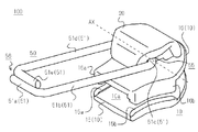
- FIG. 1 is a schematic perspective view of a fastener slider.
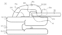
- FIG. 2 is a schematic side view of the fastener slider.
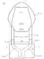
- FIG. 3 is a schematic top view of the fastener slider.
- FIG. 4 is a schematic side view of the fastener slider, showing the posture change of the handle.
- FIG. 5 is a schematic partial top view of the fastener slider, schematically showing the posture change of the handle.
- the fastener slider 100 includes a slider body 10, a pull attachment column 20, and a pull 50.
- the slider body 10 is formed by connecting a pair of upper wing plate 16 and lower wing plate 15 via a connecting column 17.
- the handle attachment column 20 is integrally provided on the upper blade 16 instead of on the lower blade 15.
- Lower flanges 15 a and 15 b that protrude toward the upper blade 16 are provided on the left and right sides of the lower blade 15.
- Upper flanges 16 a and 16 b protruding toward the lower wing plate 15 are provided on the left and right sides of the upper wing plate 16.
- the left lower flange 15a and the left upper flange 16a are disposed to face each other.
- the right lower flange 15b and the right upper flange 16b are disposed to face each other.
- the slider body 10 has a Y-shaped element guide path 10 a that extends from the rear end to the front end of the slider body 10 and is branched by a connecting column 17 between the lower blade 15 and the upper blade 16.
- the element guide path 10 a is a moving space of the fastener element defined by the upper surface of the lower wing plate 15, the lower surface of the upper wing plate 16, and the side surface of the connecting column 17.
- the element guide path 10 a is also divided by the inner side surfaces of the lower flanges 15 a and 15 b of the lower blade 15 and the inner surfaces of the upper flanges 16 a and 16 b of the upper blade 16.
- the element guide path 10a has two shoulder openings and one rear opening. The two shoulder openings are arranged at the front end of the slider body 10 and on the left and right sides of the connecting column 17. One rear port is disposed at the rear end of the slider body 10.
- a handle 50 is attached to a handle attachment column 20 fixed on the upper blade 16 of the slider body 10.
- the puller 50 is a long body having a base 55 that is the center of rotation of the puller 50 on the upper blade 16 of the slider body 10 and a free end 56 at the other end of the base 55, and is made of copper, iron, aluminum. It is comprised from the metal wire illustrated in the above.
- a rectangular ring-shaped handle 50 is formed by bending a metal wire having a predetermined length into a rectangular shape.
- the constituent material of the handle 50 is not limited to metal, and may be other elastically deformable material or may be a elastically deformable composite material.
- the handle 50 has rod portions 51a to 51e which are continuous from the right end to the left end of the wire and are named as follows. Note that the names of the bar portions are merely examples, and for example, the bar portions 51a to 51e may be sequentially referred to as the first to fifth bar portions.
- the right end bar portion 51a forms the right end of the constituent wire rod of the handle 50 and extends linearly in the left-right direction.
- the right long bar portion 51b extends linearly from the bent end between the right end bar portion 51a and itself toward the pulling attachment column 20.
- the left end bar portion 51e forms the left end of the constituent wire of the handle 50 and extends linearly in the left-right direction.
- the left elongated bar portion 51d extends linearly from the bent end between the left end rod portion 51e and itself toward the pulling attachment column 20.
- the shaft bar 51c connects the ends of the right long bar 51b and the left long bar 51d on the pulling attachment column 20 side, and extends linearly in the left-right direction.
- the handle 50 is manufactured by forming a wire with an arbitrary forming apparatus or the like. From the standpoint of connecting the right long bar 51b and the left long bar 51d, the shaft bar 51c may be called a connecting bar.
- the right long bar portion 51b and the left long bar portion 51d are arranged to face each other in parallel.
- the right end bar part 51a and the left end bar part 51e are arranged side by side, close to each other, the tip of the right end bar part 51a is located near the bent end of the left end bar part 51e, and the tip of the left end bar part 51e is the right end bar part 51a.
- the left end bar portion 51e and the shaft bar portion 51c are arranged to face each other in parallel. The same applies to the relationship between the right end rod portion 51a and the shaft rod portion 51c.
- the puller 50 is a single metal wire bent in a ring shape from the right end rod portion 51a at the right end of the wire rod to the left end rod portion 51e at the left end of the wire rod.
- the right end bar 51a and the left end bar 51e are displaced in the direction away from each other.
- the shank 51b and the left long bar 51d can be elastically displaced in directions away from each other. That is, the puller 50 is configured such that the interval between the bar portions in the longitudinal direction and the width direction can be changed.
- the pull handle mounting column 20 has a shape in which the tip of the cantilever is pushed down toward the upper blade 16.
- the pull attachment column 20 has a base portion 25a, a body portion 25b, and a tip portion 25c that are connected from the rear to the front.
- the base 25 a is connected to the upper blade 16.
- the body portion 25b is disposed on the upper blade 16 with spaces SP1 and SP2 opened.
- the tip 25c is disposed on the upper blade 16 with a space SP3 therebetween.
- the tip portion 25c has a tip portion 25m that is lowered toward the upper blade 16 so as to close the space SP2.
- the bar part 51c of the handle 50 is disposed in the space SP2 defined by the body part 25b and the tip part 25c, and the bar part 51c is allowed to rotate.
- the range of rotation of the handle 50 attached to the upper blade 16 by the handle attachment column 20 is that the right long bar 51b and the left long bar 51d of the puller 50 collide with the upper surface of the upper blade 16. The further clockwise or counterclockwise rotation is prevented. Note that the vertical distance of the space SP1 ⁇ the vertical distance of the space SP3 ⁇ the vertical distance of the space SP2.
- the pull handle mounting column 20 has a rear taper portion (taper portion) 21, an intermediate parallel portion (relay portion) 22, and a front taper portion (taper portion) 23 in this order from the rear to the front. .
- the handle 50 is in a state in which the rear taper portion 21, the intermediate parallel portion 22, and the front taper portion 23 are sandwiched from the left and right, and the rear taper portion 21, the intermediate parallel portion 22, and the front taper portion 23, the rotation of the handle 50 is suitably guided.
- the handle 50 when the handle 50 falls on the upper blade 16, the handle 50 does not necessarily sandwich the rear taper portion 21 or the front taper portion 23. However, by keeping the rear taper portion 21 or the front taper portion 23 from being pinched by the puller 50 even when the puller 50 is lying down, it is possible to effectively prevent the puller 50 from wobbling.
- the rear taper portion 21 is configured so that the left and right widths are narrowed from the front to the rear, and the right and left side surfaces thereof are inclined in synchronization so that the interval gradually decreases from the front to the rear. And a pair of right inclined surfaces 21p and a left inclined surface 21q (a set of side surfaces) inclined symmetrically in synchronization with the front-rear direction. These left and right inclined surfaces 21p and 21q are in a mirror image relationship with respect to a center line CL indicated by a two-dot chain line in FIG.
- the front taper portion 23 is also configured in the same manner as the rear taper portion 21, and its right and left side surfaces are inclined in a synchronized manner so that the interval gradually decreases from the rear to the front.
- the center line CL is an imaginary line extending in the front-rear direction at the center of the left and right.
- the intermediate parallel portion 22 is located between the rear taper portion 21 and the front taper portion 23 on the upper wing plate 16, and the right side surface 22p and the left side surface 22q are arranged to face each other in parallel. Is constant in the front-rear direction.
- the left and right inclined surfaces 21p and 21q of the rear taper portion 21 are gradually widened from the rearward-facing puller 50 side to the inverted puller 50 side. From another point of view, the left and right inclined surfaces 21p and 21q of the rear taper portion 21 are inclined along the moving direction of the fastener slider (100) and the turning direction of the handle 50 turning around the base portion 55. Inclined along.
- the rotation direction of the handle 50 is a direction in which the handle 50 rotates on the upper blade 16 around the handle attachment column 20 that holds the rotation axis of the handle 50.
- the front taper portion 23 can be described in the same manner, and the left and right inclined surfaces 23p and 23q gradually become wider from the front-facing puller 50 side to the inverted puller 50 side.
- the width of the rear taper portion 21 gradually increases from the rear to the front and becomes wider from the width W20a to the width W20b.
- the width of the intermediate parallel portion 22 is a constant width W20b in the front-rear direction.
- the width of the front taper portion 23 gradually decreases from the rear to the front, and becomes narrower from the width W20b to the width W20a.
- the pull handle attachment column 20 has the rear end width W20a, the intermediate width W20b, and the front end width W20a, and has the maximum left and right width between the rear end and the front end.
- the left and right side surfaces of the rear taper portion 21 are linearly inclined while increasing the interval from the rear to the front.
- the left and right side surfaces of the front taper portion 23 are linearly inclined while narrowing the interval from the rear to the front.
- the longitudinal length L22 of the intermediate parallel portion 22 ⁇ the longitudinal length L21 of the rear tapered portion 21 ⁇ the longitudinal length L23 of the front tapered portion 23 is satisfied.
- the posture change of the handle 50 between the rear taper portion 21 and the front taper portion 23 can be smoothed.
- the feeling of lifting the handle 50 can be different between when the handle 50 is inverted from the rear and when the handle 50 is inverted from the front.
- the puller 50 increases the interval between the right long bar 51b and the left long bar 51d that sandwich the puller mounting column 20 from the left and right in the process of transition from the lying state to the inverted state. However, it is turned upside down while sliding the left and right sides of the puller mounting column 20. Since the left and right widths of the puller attachment column 20 are expanded from the rear end to the front-rear center or from the front end to the front-rear center, the puller 50 is elastically deformed in the process of inverting the puller 50 and An interval W51 between the shank 51b and the left long bar 51d is also enlarged.
- the elastic return force guides the handle 50 to the left and right inclined surfaces 21p and 21q of the taper portion 21 in a backward direction. While moving down or being guided forward by the left and right inclined surfaces 23p, 23q of the taper portion 23, the vehicle falls while sliding on the inclined surfaces, and automatically returns from the inverted state to the lying state.
- a set of the right long bar portion 51b and the left long bar portion 51d may be simply referred to as a “nip portion” of the pull handle 50, and the distance between the pair of the right long bar portion 51b and the left long bar portion 51d.
- W51 may be referred to as the “pinch interval” of the puller 50. As shown in FIG. 3, when the handle 50 is tilted backward, the sandwiching interval W51 of the handle 50 is narrower than the maximum width W20b of the handle attachment column 20.
- the handle 50 when the handle 50 is at the A position, the handle 50 that has fallen backward is in the process of being inverted.
- the pair of extending rod portions 51b and 51d of the handle 50 slides on the left and right sides of the rear taper portion 21 and pushes outward in the left and right direction by the left and right sides of the rear taper portion 21.
- the sandwiching width W51 of the handle 50 extends outward in the left-right direction.
- the pair of extending rod portions 51b and 51d slides from the rear to the front on the left and right sides of the front taper portion 23, and the sandwiching width W51 of the handle 50 is narrowed in the left and right direction. It is not widened to the left and right by the pulling attachment column 20 or / or returns to the initial value, for example, weakly widened.
- the handle 50 When the handle 50 is released from being gripped by a human or the like, if the sandwiched portion of the handle 50 sandwiches the rear taper portion 21, the handle 50 will fall back. When the handle 50 is released from gripping by a human or the like, if the sandwiching portion of the handle 50 sandwiches the intermediate parallel portion 22, the handle 50 falls forward or backward depending on the inertial force or the like. When the handle 50 is released from being gripped by a human or the like, if the sandwiching portion of the handle 50 sandwiches the front taper portion 23, the handle 50 will fall forward. Note that the handle 50 may be held by a robot, a machine, or the like. By using magnetic force or the like, the posture of the handle 50 may be controlled without contacting the handle 50.
- the pull handle mounting column 20 has two rear taper portions 21 and a front taper portion 23, whereby the pull handle 50 is turned to the right according to the inverted position of the pull handle 50.
- the interval W51 between the long bar portion 51b and the left long bar portion 51d is widened.
- the rear side view of the fastener slider 100 of the present embodiment is substantially the same as FIG. 9 of the fourth embodiment to be described later, but the positioning taper portion 29 of FIG. 9 is not provided, and instead the rear taper portion. 21 differs in that 21 further extends to the upper blade 16 side.
- FIG. 6 is a schematic top view of the fastener slider.
- a plurality of tapered portions are not provided, but a single tapered portion is provided. Even in such a case, the same effect as the first embodiment can be obtained.
- the falling direction of the pulling handle can be restricted to a predetermined direction. In the present embodiment, only the backward fall of the handle 50 is allowed, and the forward fall of the handle 50 is prohibited.
- the long taper portion 24 is configured in a tapered shape that narrows from left to right from the front to the rear, and the left and right side surfaces thereof are gradually narrowed from the front to the rear. It is inclined and has a right inclined surface 24p and a left inclined surface 24q that are symmetrically inclined in the longitudinal direction. These left and right inclined surfaces 24p and 24q are in a mirror image relationship with respect to the center line CL indicated by the two-dot chain line in FIG.
- the left and right widths of the long taper portion 24 slowly increase from the rear to the front, and gradually increase from the width W20a to the width W20b.
- the front end of the long taper portion 24 is connected to a restricting portion 26 that restricts the handle 50 from falling forward further.
- the restricting portion 26 is a convex portion projecting forward from the pull handle mounting column 20, and the width W 26 of the restricting portion 26 is wider than the maximum width W 20 c of the long tapered portion 24, thereby further forward of the pull handle 50. Lodging is regulated. As shown in FIG. 6, the longitudinal length L21 of the long taper portion 24> the longitudinal length L26 of the restricting portion 26 is satisfied. The front / rear length L ⁇ b> 21 occupies most of the front / rear length of the pull handle mounting column 20.
- the puller 50 when the puller 50 is inverted from a lying state by gripping by a human or the like, the puller 50 is gripped from the grip of the human or the like regardless of the position of the puller 50 in the rotation direction of the puller 50.
- the handle When the handle is released, the handle 50 falls backward.
- the usability of the fastener slider 100 can be improved compared to the case where the fall direction of the handle 50 is forward.
- the principle of the automatic return of the pulling handle 50 according to the present embodiment is the same as in the first embodiment, in which the long tapered portion 24 is sandwiched by the pulling handle 50 and the left and right widths of the long tapered portion 24 in the rotation direction of the pulling handle 50. Depends on changes.
- FIG. 7 is a schematic perspective view of the fastener slider.
- FIG. 8 is a schematic top view of the fastener slider.
- the grip portion 60 is attached to the free end of the handle 50.
- both ends of the metal wire rod, which is the tip of the handle 50 are fixed by the gripping portion 60.
- the length of the right long rod portion 51b and the left long rod portion 51d is selected by appropriately selecting the material of the handle 50. By ensuring the thickness appropriately, the elastic deformation of the handle 50 can be sufficiently ensured.
- the enlargement of the sandwiching width W51 of the handle 50 is not extremely hindered, and the same effect as that of the above-described embodiment can be obtained.
- the grip 60 has a groove 62 that holds the free end of the handle 50.
- the groove part 62 has a pair of wall parts 62a, 62b facing each other in parallel with a constant groove width W62.
- the groove width W ⁇ b> 62 of the groove portion 62 is narrower than the diameter of the wire constituting the handle 50, whereby the handle 50 can be suitably sandwiched and fixed by the groove portion 62.
- the groove length of the groove portion 62 is substantially equal to the left-right width of the handle 50.
- the free end of the handle 50 has a narrowed configuration, and the constituent wire of the handle 50 is bent so that the ends are adjacent to each other at the center of the left-right width of the handle 50.
- the right end bar portion 51a of the pull handle 50 gradually approaches the left end bar portion 51e side as it extends from the bent portion between the handle 50 and the right long bar portion 51b, and then the right long bar portion 51b extends. Bends in the same direction as the direction, and is side by side with the tip end side of the left end bar portion 51e.
- the left end rod portion 51e gently approaches the right end rod portion 51a side as it extends from the bent portion between the left long rod portion 51d and then the same as the extending direction of the left long rod portion 51d. Bent in the direction and beside the front end side of the right end bar portion 51a.
- the distal end surfaces of the right end bar portion 51 a and the left end bar portion 51 e face the bottom surface of the groove portion 62 of the grip portion 60.
- the gripping portion 60 is provided at the free end of the handle 50, the sandwiching width W51 of the handle 50 is allowed to vary. Because, as described above, even if the position variation of the free end of the handle 50 is restricted by the gripper 60, the wire rod of the handle 50 that contacts the puller mounting column 20 by adjusting the material, length, size, etc. of the wire rod This is because the elastic deformation of the portion itself is not extremely hindered.
- the handle 50 is sandwiched from above and below in relation to the plane on which the handle 50 exists.
- the end portions of the handle 50 may be allowed to move in the left-right direction. In this case, the force required to widen the sandwiching width W51 of the handle 50 is reduced.
- the grip portion 60 is typically made of a metal material, and the grip portion 60 and the handle 50 are fixed between the pair of wall portions 62a and 62b in a state where the tip of the wire rod of the handle 50 is housed in the groove portion 62. This is done by caulking and fixing.
- the present invention is not limited to this aspect, and the gripping portion 60 may be integrally injection-molded with respect to the handle 50 by an elastic material such as resin or rubber. Other materials may be adopted.
- FIG. 9 is a schematic rear side view of the fastener slider, showing a state where the handle is locked.
- the present embodiment has a positioning taper portion 29 in which the left and right intervals are increased from the bottom to the top of the pull handle mounting column 20.
- the positioning taper portion 29 is formed at a position where the puller 50 can come into contact with a part of the puller 50 in the lying state, and thereby, it is possible to effectively restrict free standing of the puller 50 in the lying state.
- the handle attachment column 20 has the rear taper portion 21 and the front taper portion 23 described in the first embodiment.
- a positioning taper portion 29, a rear taper portion 21, an intermediate parallel portion 22, and a front taper portion 23 are arranged in this order along the rotation direction of the handle 50.
- This embodiment can be combined with any of the first to third embodiments described above.
- the specific aspect which positions the handle 50 is arbitrary, and should not be limited to the aspect of tapering the handle attachment column 20 disclosed in the present embodiment. For example, there is no problem even if it has an inclined surface that matches the contour shape of the metal wire, such as a tapered surface 72a of the relay portion 72 in the sixth embodiment to be described later.
- the maximum width W21c of the rear taper portion 21 satisfies the relationship of width W21a ⁇ width W21b ⁇ width W21c.
- the vertical width H21a of the positioning taper portion 29, the vertical width H21b of the rear taper portion 21, and the vertical width H21c of the intermediate parallel portion 22 satisfy the relationship of width H21c ⁇ width H21a ⁇ width H21b.
- the initial value of the sandwiching width W51 of the handle 50 is larger than the minimum left and right width W21a of the positioning taper portion 29 and smaller than the minimum width of the rear taper portion 21 (maximum width of the positioning taper portion 29) W21b.
- the handle 50 sandwiches the positioning taper portion 29, and the positioning taper portion 29 causes the right long bar portion 51 b and the left long rod portion 51 d of the handle 50. It is preferably biased so as to be separated to the left and right outside, and the pinching interval of the handle 50 is widened by the positioning taper portion 29. Thereby, the swing of the handle 50 with respect to the slider body 10 can be suppressed more suitably.
- the right long bar portion 51b and the left long bar portion 51d of the pull handle 50 slide on the left and right side surfaces of the positioning taper portion 29, and in this process, the right long bar portion 51b. And the distance W51 between the left elongated bar portion 51d gradually increase. Thereafter, the right long bar portion 51b and the left long bar portion 51d of the pull handle 50 get over the edge between the positioning taper portion 29 and the rear taper portion 21, and slide on the left and right side surfaces of the rear taper portion 21. Thus, the interval W51 between the right long bar portion 51b and the left long bar portion 51d further gradually increases.
- the right long bar portion 51 b and the left long bar portion 51 d of the puller 50 cross over the edge between the rear taper portion 21 and the intermediate parallel portion 22 and slide on the left and right side surfaces of the intermediate parallel portion 22.
- the distance between the right long bar 51b and the left long bar 51d does not change.
- the right long bar portion 51 b and the left long bar portion 51 d get over the edges of the intermediate parallel portion 22 and the front taper portion 23 and slide on the left and right side surfaces of the front taper portion 23. In this process, the interval W51 between the right long bar portion 51b and the left long bar portion 51d gradually decreases.
- the handle 50 is in a state of lying down on the front side.
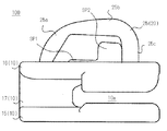
- FIG. 10 is a schematic side view of the slider body of the fastener slider.
- the pulling attachment column 20 is not configured as a cantilever, its tip 25c is fixed to the upper blade 16 and the space SP2 is completely closed. .
- the handle 50 is a wire and can be easily attached to the space SP2.
- FIG. 11A is a schematic top view of the slider body of the fastener slider in which the puller is in a lying state
- FIG. 11B is a schematic view of the slider body of the fastener slider in a cross-sectional view of the puller in the inverted state. It is a top view.
- the handle 50 may be attached to the handle attachment column 20 in order to allow rotation of the handle 50 in the left-right direction instead of the front-rear direction.
- the handle mounting column 20 is tapered in the left-right direction. Even in such a case, the same effect as that of the above-described embodiment can be ensured.
- the above-mentioned right end bar part 51a, right long bar part 51b, left end bar part 51e, and left long bar part 51d are combined with the front end bar part 51a, the front long bar part 51b, and the rear end.
- the disclosure content of the present embodiment may be understood by changing the names of the rod portion 51e and the rear long rod portion 51d.
- the handle attachment column 70 includes a left taper part (taper part) 71, a handle holding intermediate part (relay part) 72, and a right taper part (taper part) 73.
- the left taper portion 71 is configured such that the front-rear width decreases from right to left, and the front and rear side surfaces thereof are inclined so that the interval gradually decreases from right to left.
- a pair of a front inclined surface 71p and a rear inclined surface 71q which are symmetrically tuned and tilted along the line.
- These front and rear inclined surfaces 71p and 71q are in a mirror image relationship with respect to the center line CL2 indicated by the two-dot chain line in FIG.
- the center line CL ⁇ b> 2 is a virtual straight line extending left and right at the front and rear center of the pull handle attachment column 20.
- the right taper portion 73 is configured such that the front-rear width decreases from left to right, and the front and rear side surfaces thereof are inclined so that the interval gradually decreases from left to right.
- the handle holding intermediate portion 72 is a portion that relays the rotation of the handle 50 between the left taper portion 71 and the right taper portion 73, and its front side surface is recessed backward to hold the handle 50 in an inverted state. And the rear side surface is recessed forward. Thereby, when the pull handle 50 is inverted, the front long bar portion 51b and the rear long bar portion 51d are accommodated in the above-described recesses, and the inverted state of the pull handle 50 is maintained.
- the concave portion is a tapered surface 72a having a curved surface from the deepest position in the left-right direction, and is preferably hemispherical. Thereby, it is possible to suitably receive and hold a wire having a circular cross-sectional view.
- the front and rear long bar portions are removed from the recesses by pushing the free end 56 of the puller 50 in the standing state to the left or right with a sufficient force.
- the puller 50 can be automatically returned to the lying state lying on the upper blade while being guided by the left or right tapered portion.
- the automatic pulling of the puller 50 on the upper wing plate 16 has been described consistently. However, it is assumed that it is desirable to temporarily turn the puller 50 upside down as in this embodiment. Is done.
- the relay portion that can temporarily hold the handle between the left and right taper portions as in the present embodiment, it is possible to ensure primary inversion of the handle with a relatively simple configuration.
- the location where the ends of the wire constituting the handle are joined is arbitrary.
- the inclined surface of the tapered portion is not limited to a flat surface as long as it is inclined from one side to the other, and may be a curved surface.
- the left and right inclined surfaces of the tapered portion and the left and right long bar portions of the handle are preferably in surface contact within a certain range, but may be in point contact.
- the structure of the handle attachment pillar disclosed in the present application can be applied to any type of fastener slider other than the free slider, and the disclosure of the present application should not be limited to the free slider.
Landscapes
- Slide Fasteners (AREA)
Description
本発明は、ファスナースライダー及びスライドファスナーに関し、特に引手を倒伏状態に自動復帰させる機能を具備するものに関する。
様々な種類のファスナースライダーが製造開発されており、その中には、引手を倒伏状態に自動復帰させる機能を具備するものがある。
特許文献1は、同文献の図1に示すように、引手2が線条スプリング20で構成され、その両端の枢軸部21が非同一直線上に配され、かつ、一方の枢軸部21には停止爪23が設けられていることを開示する。引手2を倒立させると、引手2が捩れた状態になり、これにより、引手2が自動的に胴体1上へ横倒しに倒伏することが開示されている(同文献の段落0025及び図3等参照)。
特許文献2は、引手を倒伏状態に自動復帰させるものではなく、引手を倒立状態へ自動復帰させるファスナースライダーに関する。同文献には、同文献の図2に示すように、引手6が鋼線で環状に形成され、上翼板8上の柱体11に鋼線の一端と他端が上下に固定されることが開示されている。環状部12には倒伏時に倒立方向への応力が生じることが開示されている。
特許文献3は、引手を倒伏状態に自動復帰させるものではなく、引手を倒立状態へ自動復帰させるファスナースライダーに関する。同文献には、同文献の図23及び図24に示すように、ストラップ1の特有の形状に応じて可撓性引手2が倒立状態に復帰することを開示する。同文献の図27乃至図29についても同様である。
ところで、ファスナースライダーの胴体に対して引手が自由移動可能な自由スライダーは、簡素な構成であり、一般的に低コストで生産できる。しかしながら、自由スライダーの引手の自由な移動が、ファスナーの用途によっては好まれない場合がある。引手ロック機能を確保するべくスライダー胴体に凸部を設け、他方、引手にその凸部を挟持する構造を設けるとしても、既存の自由スライダーの引手とスライダー胴体の双方の構造を大きく変更する必要が生じてしまう。
上述の例示的な課題説明から把握されるように、簡素な構成のファスナースライダーで引手の自由移動を規制する機能を確保することが求められている。
本発明に係るファスナースライダーは、上翼板、下翼板、及び前記上翼板と前記下翼板間を連結する連結柱を備えるスライダー胴体と、前記スライダー胴体上に設けられる引手取付柱と、前記引手取付柱により前記スライダー胴体に対して回動可能に取り付けられ、前記上翼板又は前記下翼板上にて倒伏及び倒立可能な引手と、を備え、前記引手が、少なくとも部分的に弾性を有する線材から構成されるものであって、当該引手の前記回動の中心となる基部と当該基部との関係において他端にある自由端間で延在する一組の延在棒部を含み、前記引手取付柱が、一組の前記延在棒部が摺動する一組の側面を含み、該一組の側面の間隔が、倒伏状態から起立状態への姿勢変化過程の前記引手の一組の前記延在棒部の間隔を広げるべく、倒伏状態の前記引手側から倒立状態の前記引手側へ次第に広くなる。本構成によれば、簡素な構成のファスナースライダーで引手の自由移動を規制する機能を確保することができ、端的には、引手の自動倒伏機能を確保することができる。なお、本願に開示のように、引手を起立状態に保持する機能をファスナースライダーに具備させても良い。
一組の前記側面の両方が、倒伏状態の前記引手側から倒立状態の前記引手側へ次第に傾斜する、と良い。一組の前記側面の一方のみを傾斜させても良いが、両方を傾斜させることが望ましい。
前記引手取付柱が、複数の前記テーパー部を備え、複数の前記テーパー部が、前記基部を中心とした前記引手の回動方向に沿って配置されている、と良い。各テーパー部が果たす役目は任意である。
複数の前記テーパー部が、第1及び第2テーパー部を含み、前記第1テーパー部が、前記引手の前記回動方向に沿って前記第2テーパー部から離間するに応じて幅狭になるように構成されており、前記第2テーパー部が、前記引手の前記回動方向に沿って前記第1テーパー部から離間するに応じて幅狭になるように構成されている、と良い。
前記引手取付柱は、前記上翼板又は前記下翼板上において前記第1テーパー部及び第2テーパー部間を接続する中継部を含み、当該中継部は、前記引手の一組の前記延在棒部により挟み込まれる、と良い。
前記テーパー部が有する前記一組の側面が、各々、前記引手の前記回動方向に沿って同調に傾斜する、と良い。
前記引手が、一組の前記延在棒部間を接続する連結棒部を備え、当該連結棒部が、前記引手取付柱により少なくとも部分的に囲まれて前記引手取付柱と前記スライダー胴体の間で回転自在に保持されている、と良い。
前記スライダー胴体上に配される前記引手取付柱が、スライダー胴体から離間する方向において変化する幅を有し、これにより、スライダー胴体上に前記引手がロックする、と良い。
本発明に係るスライドファスナーは、上述のいずれかのファスナースライダーを備えるスライドファスナー。
本発明によれば、簡素な構成のファスナースライダーで引手の自由移動を規制する機能を確保することができる。
以下、図面を参照しつつ、本発明の実施形態について説明する。各実施形態は、個々に独立したものではなく、過剰説明をするまでもなく、当業者をすれば、適宜、組み合わせ可能であり、この組み合わせによる相乗効果も把握可能である。実施形態間の重複説明は、原則的に省略する。参照図面は、発明説明を主目的とするものであり、適宜、簡略化されている。
以下、各図を参照して説明する際、左右一対のファスナーストリンガーに挿着した状態のファスナースライダーの移動方向を基準として、ファスナーエレメントを噛み合わせる方向を「前」、ファスナーエレメントの噛合いを解除する方向を「後」とする。なお、ファスナーストリンガーとは、本技術分野では周知のように、ファスナーテープの側縁にファスナーエレメントが固定されたものである。また、ファスナーエレメントは、本技術分野では周知のように、連続したコイル、金属や樹脂エレメントの列等を包含する用語である。
更に、ファスナースライダーにより開閉される左右一対のファスナーストリンガーを基準として、「左」、「右」という用語を用いる。この説明から把握される左右方向は、図1に示す場合、ファスナースライダーの引手取付柱に取り付けられた引手の回転軸AXに一致し、図11に示す場合、引手の回転軸AXと直交関係にある。なお、上述の説明から把握される前後方向は、図1に示す場合の回転軸AXと直交関係にあり、図11に示す場合、引手の回転軸AXに一致する。
更に、ファスナースライダーの上下翼板を連結する連結柱の延在方向を基準として「上」、「下」という用語を用いる。この説明から把握される上下方向は、図1及び図11に示す場合の回転軸AXと直交関係にある。
以上、本発明を分かりやすく説明するために前後、左右、上下を定義したが、図面を参考にすれば、例えば図3における紙面上においてファスナースライダーから見て紙面上側が前、下側が後ろとなる。また同紙面上においてファスナースライダーから見て左側が左、右側が右となる。図2における紙面上において、ファスナースライダーから見て紙面上側が上、下側が下となる。なお、各方向はファスナーストリンガーの一部を基準として説明しているが、当業者であれば、ファスナースライダーから容易にファスナーストリンガーの位置関係は想像がつくので、あえて図示はしない。
<第1実施形態>
図1乃至図5を参照して第1実施形態について説明する。図1は、ファスナースライダーの概略的な斜視図である。図2は、ファスナースライダーの概略的な側面図である。図3は、ファスナースライダーの概略的な上面図である。図4は、ファスナースライダーの概略的な側面図であり、引手の姿勢変化を示す。図5は、ファスナースライダーの概略的な部分上面図であり、引手の姿勢変化を模式的に示す。
図1乃至図5を参照して第1実施形態について説明する。図1は、ファスナースライダーの概略的な斜視図である。図2は、ファスナースライダーの概略的な側面図である。図3は、ファスナースライダーの概略的な上面図である。図4は、ファスナースライダーの概略的な側面図であり、引手の姿勢変化を示す。図5は、ファスナースライダーの概略的な部分上面図であり、引手の姿勢変化を模式的に示す。
図1及び図2に示すように、ファスナースライダー100は、スライダー胴体10、引手取付柱20及び引手50を有する。スライダー胴体10は、一対の上翼板16及び下翼板15が連結柱17を介して連結したものである。本例では、下翼板15上ではなく、上翼板16上に引手取付柱20が一体的に設けられている。下翼板15の左右側部には、上翼板16に向けて突出した下フランジ15a、15bが設けられている。上翼板16の左右側部には、下翼板15に向けて突出した上フランジ16a、16bが設けられている。左側下フランジ15aと左側上フランジ16aとは、互いに対向配置されている。右側下フランジ15bと右側上フランジ16bとは、互いに対向配置されている。
スライダー胴体10は、下翼板15と上翼板16との間に、スライダー胴体10の後端から前端へ延在し、連結柱17により分岐したY字形のエレメント案内路10aを有する。エレメント案内路10aは、下翼板15の上面、上翼板16の下面、及び連結柱17の側面によって区画されたファスナーエレメントの移動空間である。エレメント案内路10aは、下翼板15の下フランジ15a、15bの内側面及び上翼板16の上フランジ16a、16bの内側面によっても区画されている。エレメント案内路10aは、2つの肩口と1つの後口を有する。2つの肩口は、スライダー胴体10の前端にあって、連結柱17の左右に配されている。1つの後口は、スライダー胴体10の後端に配されている。
図1に示すように、スライダー胴体10の上翼板16上に固定された引手取付柱20には引手50が取り付けられる。引手50は、スライダー胴体10の上翼板16上での引手50の回動の中心となる基部55及び基部55の他端にある自由端56を有する長尺体であり、銅、鉄、アルミニウム等に例示される金属線から構成される。例えば、所定長の金属線を矩形状に屈曲させることで、矩形輪状の引手50が構成される。引手50の構成材料は金属に限らず、弾性変形可能な他の材料でも構わず、また弾性変形可能な複合材料であっても構わない。
図1に示すように、引手50は、線材の右端から左端にかけて連続し、かつ次のように命名された棒部51a~51eを有する。なお、棒部の呼び名は一例にすぎず、例えば、棒部51a~51eを順に第1乃至第5棒部と呼んでも良い。
右端棒部51aは、引手50の構成線材の右端を成し、左右方向に直線的に延在する。右長尺棒部51bは、右端棒部51aと自身の間の屈曲端から引手取付柱20に向かって直線的に延在する。左端棒部51eは、引手50の構成線材の左端を成し、左右方向に直線的に延在する。左長尺棒部51dは、左端棒部51eと自身の間の屈曲端から引手取付柱20に向かって直線的に延在する。軸棒部51cは、引手取付柱20側の右長尺棒部51b及び左長尺棒部51dの各端部同士を連結し、左右方向に直線的に延在する。引手50は、任意の成形装置等により線材を成形することで製造される。右長尺棒部51b及び左長尺棒部51d間を連結するという見地から軸棒部51cを連結棒部と呼んでも良い。
右長尺棒部51b、左長尺棒部51dは、平行に対向配置されている。右端棒部51a、左端棒部51eは、横並びに近接配置しており、右端棒部51aの先端が左端棒部51eの屈曲端寄りに位置し、左端棒部51eの先端が右端棒部51aの屈曲端寄りに位置する。左端棒部51eと軸棒部51cとは平行に対向配置されている。右端棒部51aと軸棒部51cとの関係についても同様である。以上のように、引手50は、線材右端の右端棒部51aから線材左端の左端棒部51eにかけてリング状に曲折した1本の金属線材である。軸棒部51cを回転軸として引手50が回動して引手50自体の輪郭形状が弾性的に変化する過程において、右端棒部51aと左端棒部51eはそれぞれ離れる方向に変位し、また右長尺棒部51bと左長尺棒部51dがそれぞれ離れる方向に弾性的に変位することができる。つまり、引手50は、その長手方向及び幅方向の棒部間隔が変動可能に構成されている。
図2に示すように、引手取付柱20は、片持ち梁の先端が上翼板16に向けて押し倒された形状を有する。引手取付柱20は、後方から前方へ連結した基部25a、胴部25b、及び先端部25cを有する。基部25aは、上翼板16に連結している。胴部25bは、上翼板16上に空間SP1、SP2をあけて配されている。先端部25cは、上翼板16上に空間SP3をあけて配されている。先端部25cは、空間SP2を閉じるように上翼板16側へ下降した先端部25mを有する。胴部25bと先端部25cにより規定された空間SP2に引手50の棒部51cが配され、棒部51cの回動が許容される。引手取付柱20により上翼板16上に取り付けられた引手50の回動範囲は、引手50の右長尺棒部51bと左長尺棒部51dが上翼板16の上面に衝突することにより、その更なる時計周り又は反時計周りの回動が阻止される。なお、空間SP1の上下間隔<空間SP3の上下間隔<空間SP2の上下間隔を満足する。
図3を参照して更に説明する。図3に示すように、引手取付柱20は、後方から前方にこの順で、リアテーパー部(テーパー部)21、中間平行部(中継部)22、及びフロントテーパー部(テーパー部)23を有する。引手50の回動過程において、引手50は、リアテーパー部21、中間平行部22、及びフロントテーパー部23を左右から挟持した状態にあり、リアテーパー部21、中間平行部22、及びフロントテーパー部23により引手50の回動が好適に案内される。
なお、上翼板16上に引手50が倒伏したとき、引手50がリアテーパー部21又はフロントテーパー部23を必ずしも挟み込んでいる必要はない。しかしながら、引手50の倒伏状態においても引手50によるリアテーパー部21又はフロントテーパー部23の挟み込みを保つことにより、引手50のぶらつきを効果的に抑制することができる。
リアテーパー部21は、前方から後方へ左右幅が狭くなるように構成されており、その左右側面が前方から後方へ徐々に間隔が狭くなるように同調して傾斜付けられており、端的には、前後方向に沿って対称的に同調して傾斜した一組の右傾斜面21pと左傾斜面21q(一組の側面)を有する。これら左右の傾斜面21p、21qは、図3の二点鎖線で示す中心線CLを基準として鏡像の関係にある。フロントテーパー部23もリアテーパー部21と同様に構成されており、その左右側面が後方から前方へ徐々に間隔が狭くなるように同調して傾斜付けられており、端的には、前後方向に沿って対称的に同調傾斜した一組の右傾斜面23pと左傾斜面23qを有する。これら左右の傾斜面23q、23qは、中心線CLを基準として鏡像の関係にある。なお、中心線CLは、左右中央にて前後方向に延びる仮想線である。他方、中間平行部22は、上翼板16上でリアテーパー部21とフロントテーパー部23の間にあって、その右側面22pと左側面22qは、平行に対向配置されており、各面の左右間隔が前後方向において一定である。
リアテーパー部21の左右の傾斜面21p、21qは、後方倒伏状態の引手50側から倒立状態の引手50側へ次第に広くなる。別の観点から述べれば、リアテーパー部21の左右の傾斜面21p、21qは、ファスナースライダー(100)の移動方向に沿って傾斜し、かつ基部55を中心に回動する引手50の回動方向に沿って傾斜している。なお、引手50の回動方向は、引手50の回転軸を保持した引手取付柱20周りに引手50が上翼板16上で回動する方向である。フロントテーパー部23についても同様に説明することができ、その左右の傾斜面23p、23qは、前方倒伏状態の引手50側から倒立状態の引手50側へ次第に広くなる。
リアテーパー部21の幅は、後方から前方へ徐々に増加し、幅W20aから幅W20bへ幅広になる。中間平行部22の幅は、前後方向において一定幅W20bである。フロントテーパー部23の幅は、後方から前方へ徐々に減少し、幅W20bから幅W20aへ幅狭になる。このように、引手取付柱20は、後端幅W20a、中間幅W20b、及び前端幅W20aを有し、後端と前端との間に左右幅の最大値を有する。リアテーパー部21の左右側面は、後方から前方へ間隔を広げつつ、直線的に傾斜している。フロントテーパー部23の左右側面は、後方から前方へ間隔を狭めつつ、直線的に傾斜している。
図3に示すように、中間平行部22の前後長L22<リアテーパー部21の前後長L21<フロントテーパー部23の前後長L23を満足する。前後長L22を最少とすることで、リアテーパー部21、フロントテーパー部23間に亘る引手50の姿勢変化を円滑化することができる。前後長L21<前後長L23とすることで、後方から引手50を倒立させる場合と前方から引手50を倒立させる場合との間で引手50の持ち上げ感覚を異ならせることができる。
図3から把握可能なように、引手50は、倒伏状態から倒立状態に推移する過程で、引手取付柱20を左右から挟み込む右長尺棒部51bと左長尺棒部51d間の間隔を広げながら、引手取付柱20の左右側部を摺動しつつ倒立する。引手取付柱20の後端から前後中央へ又は前端から前後中央へ引手取付柱20の左右幅が拡大しているため、引手50を倒立させる過程で引手50が弾性変形し、引手50の右長尺棒部51bと左長尺棒部51d間の間隔W51も拡大する。なお、引手50は、ヒト等による把持から解放されると、その弾性復帰力により、後方へテーパー部21の左右の傾斜面21p、21qに案内されながら、詳細にはそれらの傾斜面上を摺動しながら倒伏し、又は前方へテーパー部23の左右の傾斜面23p、23qに案内されながら、それらの傾斜面上を摺動しながら倒伏し、倒立状態から倒伏状態へと自動復帰する。以下、右長尺棒部51bと左長尺棒部51dの組を単に引手50の「挟み込み部」と呼ぶ場合があり、一組の右長尺棒部51bと左長尺棒部51dの間隔W51を引手50の「挟み込み間隔」と呼ぶ場合がある。図3に示すように、引手50が後方へ倒伏しているとき、引手50の挟み込み間隔W51は、引手取付柱20の最大幅W20bよりも狭い。
図4及び図5を参照して引手50の姿勢変化の過程を詳細に説明する。図4に示すA位置からB位置へ引手50が回動するとき、引手50は、引手取付柱20の左右側部を摺動しつつ倒立し、この過程で上述の挟み込み間隔が拡大する。図5に模試的に示すように、引手50の右長尺棒部51bと左長尺棒部51dの移動軌跡は、引手取付柱20の左右側部の輪郭に沿ったものになる。なお、以下、右長尺棒部51b、左長尺棒部51dを延在棒部と呼ぶ場合がある。
図4及び図5に示すように、引手50がA位置にある時、後方へ倒伏した引手50が倒立する過程にある。引手50を倒立させる過程で、引手50の一組の延在棒部51b、51dが、リアテーパー部21の左右側部を摺動し、リアテーパー部21の左右側部により左右方向外側へ押され、これにより、引手50の挟み込み幅W51が左右方向外側に広がる。
図5に示すように、A位置からB位置へ引手50が回動する過程で、一組の延在棒部51b、51dがリアテーパー部21と中間平行部22間の縁27を乗り越え、これにより、引手50の挟み込み幅W51が引手取付柱20の最大幅20bに一致する。この状態のとき、引手50は、上翼板16上に略直立した状態にある。この状態からB位置へ引手50が回動する過程で、一組の延在棒部51b、51dが中間平行部22とフロントテーパー部23間の縁28を乗り越え、その後、引手50の弾性復帰力に応じて上述の幅W51が自ずと狭くなっていく。引手50の弾性復帰力に応じて、一組の延在棒部51b、51dが、フロントテーパー部23の左右側部を後方から前方へ摺動し、引手50の挟み込み幅W51が左右方向に狭まり、引手取付柱20により左右に広げられていない/又は適当に、例えば弱く広げられた初期値へ戻る。
ヒト等による把持から引手50が解放されるとき、引手50の挟み込み部がリアテーパー部21を挟んでいれば、後方へ引手50が倒伏する。ヒト等による把持から引手50が解放されるとき、引手50の挟み込み部が中間平行部22を挟んでいれば、引手50は、慣性力等に応じて前方又は後方へ倒伏する。ヒト等による把持から引手50が解放されるとき、引手50の挟み込み部がフロントテーパー部23を挟んでいれば、前方へ引手50が倒伏する。なお、ロボット、機械等により引手50を把持しても構わない。磁力等の活用により、引手50と接触することなく引手50の姿勢を制御しても構わない。
上述の説明から明らかなように、本実施形態においては、引手取付柱20が、2つのリアテーパー部21とフロントテーパー部23を有し、これにより、引手50の倒立に応じて引手50の右長尺棒部51b、左長尺棒部51d間の間隔W51が広げられる。これにより、自由スライダーの簡素な構成を維持しつつ、引手の自由移動を規制する機能を確保することができる。ヒト等による把持から引手50が解放されれば、引手50自体の弾性復帰力に応じて引手50は自動的に倒立状態から倒伏状態へ推移する。
本構成によれば、例えば、引手50を上翼板16に位置固定するための嵌合構造を引手50と上翼板16に設ける必要がなく、つまり、ファスナースライダーの構成の複雑化を回避することができる。スライダー胴体10の成型金型に変更をする必要があるが、引手50自体は既存のものを活用することができる。
なお、本実施形態のファスナースライダー100の後側面図は、後述の第4実施形態の図9と略同様であるが、図9の位置決めテーパー部29が設けられていなく、その代わりにリアテーパー部21が上翼板16側へ更に延長している点で異なる。
<第2実施形態>
図6を参照して第2実施形態について説明する。図6は、ファスナースライダーの概略的な上面図である。図6から理解できるように、本実施形態においては、複数のテーパー部を設けず、単一のテーパー部を設ける。このような場合であっても第1実施形態と同様の効果を得ることができる。本実施形態のようにテーパー部の前後長を十分に確保することで、引手の倒伏方向を所定方向に規制することもできる。なお、本実施形態では、引手50の後方倒伏のみが許容され、引手50の前方倒伏は禁止されている。
図6を参照して第2実施形態について説明する。図6は、ファスナースライダーの概略的な上面図である。図6から理解できるように、本実施形態においては、複数のテーパー部を設けず、単一のテーパー部を設ける。このような場合であっても第1実施形態と同様の効果を得ることができる。本実施形態のようにテーパー部の前後長を十分に確保することで、引手の倒伏方向を所定方向に規制することもできる。なお、本実施形態では、引手50の後方倒伏のみが許容され、引手50の前方倒伏は禁止されている。
図6に示すように、長尺テーパー部24は、前方から後方へ左右から幅狭になるテーパー状に構成されており、その左右側面が前方から後方へ徐々に間隔が狭くなるようにとなるべく傾斜付けられており、端的には、前後方向に沿って対称的に同調傾斜した右傾斜面24pと左傾斜面24qを有する。これら左右の傾斜面24p、24qは、図6の二点鎖線で示す中心線CLを基準として鏡像の関係にある。長尺テーパー部24の左右幅は、後方から前方へ緩慢に拡大し、幅W20aから幅W20bまで緩慢に幅広になる。長尺テーパー部24の前端には、引手50の更なる前方への倒伏を規制する規制部26が連結している。規制部26は、引手取付柱20から前方へ突出した凸部であり、規制部26の幅W26は、長尺テーパー部24の最大幅W20cよりも広く、これにより、引手50の更なる前方への倒伏が規制される。図6に示すように、長尺テーパー部24の前後長L21>規制部26の前後長L26を満足する。前後長L21は、引手取付柱20の前後長の大部分を占める。
このような構成とすることで、引手50をヒト等による把持によって倒伏状態から倒立させた時、引手50の回動方向にて引手50がどの位置にあっても、ヒト等の把持から引手50が解放されると引手50が後方へ倒伏する。本実施形態のように引手50の倒伏方向を後方とすることにより、引手50の倒伏方向が前方の場合と比較して、ファスナースライダー100の使い勝手を向上させることができる。なお、本実施形態に係る引手50の倒伏自動復帰の原理は、第1実施形態と同様、引手50による長尺テーパー部24の挟み込みと引手50の回動方向における長尺テーパー部24の左右幅の変化に依存する。
<第3実施形態>
図7及び図8を参照して第3実施形態について説明する。図7は、ファスナースライダーの概略的な斜視図である。図8は、ファスナースライダーの概略的な上面図である。図7及び図8から理解できるように、本実施形態においては、第1実施形態とは異なり、引手50の自由端に把持部60を取り付ける。このような場合、引手50の先端である金属線材の両端が把持部60によって固定されるが、引手50の材質を適当に選定して右長尺棒部51bと左長尺棒部51dの長さを適当に確保することにより引手50の弾性変形を十分に確保することができる。また、かかる構成によれば、引手50の挟み込み幅W51の拡大が極端に阻害されることはなく、上述の実施形態と同様の効果を得ることができる。第2実施形態に係るファスナースライダーに対して本実施形態に係る把持部を設けても良い。
図7及び図8を参照して第3実施形態について説明する。図7は、ファスナースライダーの概略的な斜視図である。図8は、ファスナースライダーの概略的な上面図である。図7及び図8から理解できるように、本実施形態においては、第1実施形態とは異なり、引手50の自由端に把持部60を取り付ける。このような場合、引手50の先端である金属線材の両端が把持部60によって固定されるが、引手50の材質を適当に選定して右長尺棒部51bと左長尺棒部51dの長さを適当に確保することにより引手50の弾性変形を十分に確保することができる。また、かかる構成によれば、引手50の挟み込み幅W51の拡大が極端に阻害されることはなく、上述の実施形態と同様の効果を得ることができる。第2実施形態に係るファスナースライダーに対して本実施形態に係る把持部を設けても良い。
図7及び図8に示すように、把持部60は、引手50の自由端を保持する溝部62を有する。溝部62は、一定の溝幅W62あけて平行に対向した一組の壁部62a、62bを有する。例えば、溝部62の溝幅W62は、引手50を構成する線材の径よりも狭く、これにより、好適に、引手50を溝部62により挟み込み固定することができる。溝部62の溝長は、引手50の左右幅に略等しい。
図8に示すように、引手50の自由端は窄んだ構成となっており、引手50の構成線材が引手50の左右幅の中央で各端部が隣り合うように屈曲されている。引手50の右端棒部51aは、右長尺棒部51bとの間の屈曲部分から延在するに応じて左端棒部51e側へ緩やかに近接し、その後、右長尺棒部51bの延在方向と同方向へ屈曲して左端棒部51eの先端側と横並びになる。左端棒部51eは、左長尺棒部51dとの間の屈曲部分から延在するに応じて右端棒部51a側へ緩やかに近接し、その後、左長尺棒部51dの延在方向と同方向へ屈曲して右端棒部51aの先端側と横並びになる。右端棒部51a、左端棒部51eの先端面は、把持部60の溝部62の底面に対向する。
把持部60を引手50の自由端に設けたとしても、引手50の挟み込み幅W51の変動は許容される。なぜなら、上述したように引手50の自由端の位置変動を把持部60により規制したとしても、線材の材質、長さ、更には大きさ等の調整によって引手取付柱20に接触する引手50の線材部分自体の弾性変形は極端に妨げられないためである。
本実施形態では、引手50が存在する平面との関係においてその上下から引手50を挟み込む。図8の点線矢印で模式的に示すように、引手50の各端部の左右方向の移動を許容しても良く、この場合、引手50の挟み込み幅W51の拡幅に必要な力を低減することができる。把持部60は、典型的には金属材から構成され、把持部60と引手50間の固定は、引手50の線材の先端を溝部62に収納した状態で一対の壁部62a、62bによって線材を加締め固定することにより為される。しかしながら、この態様に限定されるべきものではなく、例えば樹脂、ゴム等の弾性材料によって把持部60を引手50に対して一体的に射出成形しても構わない。また他の材料を採用しても構わない。
<第4実施形態>
図9を参照して第4実施形態について説明する。図9は、ファスナースライダーの概略的な後側面模式図であり、引手がロックされた状態を示す。図9から理解できるように、本実施形態においては、引手取付柱20の下から上へ左右間隔が拡大した位置決めテーパー部29を有する。位置決めテーパー部29は、引手50が倒伏状態において引手50の一部と接触可能な位置に形成され、これにより、倒伏状態の引手50が自由に起立することを効果的に規制することができる。なお、本実施形態においても、引手取付柱20は、第1実施形態において説明したリアテーパー部21及びフロントテーパー部23を有している。引手50の回動方向に沿って、位置決めテーパー部29、リアテーパー部21、中間平行部22、及びフロントテーパー部23が順に配置されている。本実施形態は、上述の第1乃至第3実施形態のいずれとも組み合わせることができる。なお、引手50を位置決めする具体的な態様は任意であり、本実施形態に開示の引手取付柱20のテーパー付けの態様に限定されるべきものではない。例えば、後述する第6実施形態における中継部72のテーパ面72aのように、金属線の輪郭形状にあった傾斜面を有するもととしても問題ない。
図9を参照して第4実施形態について説明する。図9は、ファスナースライダーの概略的な後側面模式図であり、引手がロックされた状態を示す。図9から理解できるように、本実施形態においては、引手取付柱20の下から上へ左右間隔が拡大した位置決めテーパー部29を有する。位置決めテーパー部29は、引手50が倒伏状態において引手50の一部と接触可能な位置に形成され、これにより、倒伏状態の引手50が自由に起立することを効果的に規制することができる。なお、本実施形態においても、引手取付柱20は、第1実施形態において説明したリアテーパー部21及びフロントテーパー部23を有している。引手50の回動方向に沿って、位置決めテーパー部29、リアテーパー部21、中間平行部22、及びフロントテーパー部23が順に配置されている。本実施形態は、上述の第1乃至第3実施形態のいずれとも組み合わせることができる。なお、引手50を位置決めする具体的な態様は任意であり、本実施形態に開示の引手取付柱20のテーパー付けの態様に限定されるべきものではない。例えば、後述する第6実施形態における中継部72のテーパ面72aのように、金属線の輪郭形状にあった傾斜面を有するもととしても問題ない。
図9に示すように、位置決めテーパー部(位置決め部/位置決め手段)29の最小左右幅W21a、リアテーパー部21の最小幅(位置決めテーパー部29の最大幅)W21b、中間平行部22の左右幅(リアテーパー部21の最大幅)W21cは、幅W21a<幅W21b<幅W21cの関係を満足する。位置決めテーパー部29の上下幅H21a、リアテーパー部21の上下幅H21b、中間平行部22の上下幅H21cは、幅H21c<幅H21a<幅H21bの関係を満足する。
引手50の挟み込み幅W51の初期値は、位置決めテーパー部29の最小左右幅W21aよりも大きく、リアテーパー部21の最小幅(位置決めテーパー部29の最大幅)W21bよりも小さい。これにより、上翼板16上に引手50が倒伏しているとき、引手50の自重等により引手50が倒立することが抑制される。このように、引手50が倒伏状態において引手50の一部と接触可能な位置に上下方向に幅が変動するテーパー部を設けることにより引手50を好適にロックすることができる。
上翼板16上に引手50が倒伏した状態において、引手50が位置決めテーパー部29を挟み込んだ状態にあり、位置決めテーパー部29によって引手50の右長尺棒部51bと左長尺棒部51dが左右外側へ離間するように付勢され、引手50の挟み込み間隔が位置決めテーパー部29により広げられた状態にあることが好ましい。これにより、スライダー胴体10に対する引手50のぶらつきをより好適に抑制することができる。
倒伏状態の引手50を倒立させる場合、引手50の右長尺棒部51bと左長尺棒部51dは、位置決めテーパー部29の左右側面上を摺動し、この過程で右長尺棒部51bと左長尺棒部51d間の間隔W51が徐々に拡大する。その後、引手50の右長尺棒部51bと左長尺棒部51dは、位置決めテーパー部29とリアテーパー部21間の縁を乗り越え、リアテーパー部21の左右側面上を摺動し、この過程で右長尺棒部51bと左長尺棒部51d間の間隔W51が更に徐々に拡大する。その後、引手50の右長尺棒部51bと左長尺棒部51dは、リアテーパー部21と中間平行部22間の縁を乗り越え、中間平行部22の左右側面上を摺動する。引手50の右長尺棒部51bと左長尺棒部51dが中間平行部22の左右側面上を摺動する際、右長尺棒部51bと左長尺棒部51d間の間隔は変化しない。その後、右長尺棒部51bと左長尺棒部51dは、中間平行部22とフロントテーパー部23の縁を乗り越え、フロントテーパー部23の左右側面上を摺動する。この過程で右長尺棒部51bと左長尺棒部51d間の間隔W51が徐々に減少する。フロントテーパー部23を摺動し終えると引手50は前方側に倒伏した状態となる。
<第5実施形態>
図10を参照して第5実施形態について説明する。図10は、ファスナースライダーのスライダー胴体の概略的な側面図である。図10から理解できるように、本実施形態においては、引手取付柱20が片持ち梁として構成されておらず、その先端部25cが上翼板16に固定され、空間SP2が完全に閉じている。このように引手取付柱20が上翼板16の上面に両端固定した場合であっても上述の実施形態と同様の効果を得ることができる。引手50は、線材であり、空間SP2への取付は容易である。
図10を参照して第5実施形態について説明する。図10は、ファスナースライダーのスライダー胴体の概略的な側面図である。図10から理解できるように、本実施形態においては、引手取付柱20が片持ち梁として構成されておらず、その先端部25cが上翼板16に固定され、空間SP2が完全に閉じている。このように引手取付柱20が上翼板16の上面に両端固定した場合であっても上述の実施形態と同様の効果を得ることができる。引手50は、線材であり、空間SP2への取付は容易である。
<第6実施形態>
図11を参照して第6実施形態について説明する。図11(a)は、引手が倒伏状態のファスナースライダーのスライダー胴体の概略的な上面図であり、図11(b)は、倒立状態の引手を断面視したファスナースライダーのスライダー胴体の概略的な上面図である。図11から理解できるように、前後方向ではなく左右方向の引手50の回動を許容するべく、引手取付柱20に対して引手50を取り付けても良く、この場合、第1実施形態と同様の引手50の自動倒伏復帰を確保するべく、左右方向において引手取付柱20をテーパー付けする。このような場合であっても上述の実施形態と同様の効果を確保することができる。
図11を参照して第6実施形態について説明する。図11(a)は、引手が倒伏状態のファスナースライダーのスライダー胴体の概略的な上面図であり、図11(b)は、倒立状態の引手を断面視したファスナースライダーのスライダー胴体の概略的な上面図である。図11から理解できるように、前後方向ではなく左右方向の引手50の回動を許容するべく、引手取付柱20に対して引手50を取り付けても良く、この場合、第1実施形態と同様の引手50の自動倒伏復帰を確保するべく、左右方向において引手取付柱20をテーパー付けする。このような場合であっても上述の実施形態と同様の効果を確保することができる。
なお、引手50の命名について、上述の右端棒部51a、右長尺棒部51b、左端棒部51e、及び左長尺棒部51dを、前端棒部51a、前長尺棒部51b、後端棒部51e、及び後長尺棒部51dと呼び名を変えて本実施形態の開示内容を理解しても良い。上述の第1乃至第5棒部という理解の元で引手50の各部分を把握する場合には、特に実施形態間の各部分の命名変更の必要は生じない。
図11に示すように、引手取付柱70は、左テーパー部(テーパー部)71、引手保持中間部(中継部)72、及び右テーパー部(テーパー部)73を具備する。左テーパー部71は、右から左へ前後幅が狭くなるように構成されており、その前後側面が右から左へ徐々に間隔が狭くなるように傾斜付けられており、端的には、左右方向に沿って対称的に同調傾斜した一組の前傾斜面71pと後傾斜面71qを有する。これら前後の傾斜面71p、71qは、図11の二点鎖線で示す中心線CL2を基準として鏡像の関係にある。なお、中心線CL2は、引手取付柱20の前後中央にて左右に延びる仮想直線である。右テーパー部73は、左から右へ前後幅が狭くなるように構成されており、その前後側面が左から右へ徐々に間隔が狭くなるように傾斜付けられており、端的には、左右方向に沿って対称的に同調傾斜した一組の前傾斜面73pと後傾斜面73qを有する。
引手保持中間部72は、左テーパー部71と右テーパー部73の間の引手50の回動を中継する部分であり、倒立状態の引手50を保持するべく、その前側面が後方へ凹状に窪んでおり、かつその後側面が前方へ凹状に窪んでいる。これにより引手50が倒立したとき、その前長尺棒部51bと後長尺棒部51dが上述の各凹部に収まり、引手50の倒立状態が維持される。凹部は、最も深い位置から左右方向に向けて曲面を有するテーパ面72aとなっており、好適には半球状である。これにより、断面視円形の線材を好適に受け入れ保持することができる。なお、引手50を倒伏状態へ姿勢変化させる場合、起立状態の引手50の自由端56を左又は右へ十分な力で押すことにより、凹部から前及び後長尺棒部を脱しさせ、上述の実施形態と同様、左又は右テーパー部によりガイドされながら上翼板上に寝た倒伏状態へ引手50を自動復帰させることができる。
第1の実施形態においては一貫して引手50を上翼板16上に自動倒伏させることについて述べてきたが、本実施形態のように、一時的に引手50を倒立させることが望ましい場合も想定される。本実施形態のように左右のテーパー部間に引手を一時的に保持可能な中継部を設けることにより、比較的簡便な構成にて引手の一次的な倒立を確保することができる。
上述の教示を踏まえると、当業者をすれば、各実施形態に対して様々な変更を加えることができる。請求の範囲に盛り込まれた符号は、参考のためであり、請求の範囲を限定解釈する目的で参照されるべきものではない。引手を構成する線材の各端部が結合する箇所は任意である。テーパー部の傾斜面は一方から他方へ向けて傾斜していればよく平坦面に限らず、湾曲面であってよい。テーパー部の左右の傾斜面と引手の左右の長尺棒部とは、ある範囲内で面接触していることが好ましいが、点接触していても良い。引手を構成する一組の延在棒部を別々の線材で構成しても良い。自由スライダー以外の任意のタイプのファスナースライダーに対して本願に開示の引手取付柱の構成を適用することができ、本願の開示は、自由スライダーに限定されるべきものではない。
100 :ファスナースライダー
10 :スライダー胴体
15 :下翼板
16 :上翼板
17 :連結柱
20 :引手取付柱
21 :リアテーパー部
22 :中間平行部
23 :フロントテーパー部
25a :基部
25b :胴部
25c :先端部
25m :先端部
26 :規制部
27 :縁
28 :縁
50 :引手
55 :基端
56 :自由端
60 :把持部
62 :溝部
10 :スライダー胴体
15 :下翼板
16 :上翼板
17 :連結柱
20 :引手取付柱
21 :リアテーパー部
22 :中間平行部
23 :フロントテーパー部
25a :基部
25b :胴部
25c :先端部
25m :先端部
26 :規制部
27 :縁
28 :縁
50 :引手
55 :基端
56 :自由端
60 :把持部
62 :溝部
Claims (9)
- 上翼板(16)、下翼板(15)、及び前記上翼板(16)と前記下翼板(15)間を連結する連結柱(17)を備えるスライダー胴体(10)と、
前記スライダー胴体(10)上に設けられる引手取付柱(20)と、
前記引手取付柱(20)により前記スライダー胴体(10)に対して回動可能に取り付けられ、前記上翼板(16)又は前記下翼板(15)上にて倒伏及び倒立可能な引手(50)と、を備え、
前記引手(50)が、少なくとも部分的に弾性を有する線材から構成されるものであって、当該引手(50)の前記回動の中心となる基部と当該基部との関係において他端にある自由端間で延在する一組の延在棒部(51b、51d)を含み、
前記引手取付柱(20)が、一組の前記延在棒部(51b、51d)が摺動する一組の側面(21p、21q、23p、23q、71p、71q、73p、73q)を含み、
当該一組の側面(21p、21q、23p、23q、71p、71q、73p、73q)の間隔が、倒伏状態から起立状態への姿勢変化過程の前記引手(50)の一組の前記延在棒部(51b、51d)の間隔を広げるべく、倒伏状態の前記引手側から倒立状態の前記引手側へ次第に広くなる、ファスナースライダー。 - 一組の前記側面(21p、21q、23p、23q、71p、71q、73p、73q)の両方が、倒伏状態の前記引手側から倒立状態の前記引手側へ次第に傾斜する、請求項1に記載のファスナースライダー。
- 前記引手取付柱(20)が、複数の前記テーパー部(21、23、71、73)を備え、
複数の前記テーパー部(21、23、71、73)が、前記基部を中心とした前記引手の回動方向に沿って配置されている、請求項1又は2に記載のファスナースライダー。 - 複数の前記テーパー部(21、23、71、73)が、第1及び第2テーパー部(21、23、71、73)を含み、
前記第1テーパー部(21、71)が、前記引手(50)の前記回動方向に沿って前記第2テーパー部(23、73)から離間するに応じて幅狭になるように構成されており、
前記第2テーパー部(23、73)が、前記引手(50)の前記回動方向に沿って前記第1テーパー部(21、71)から離間するに応じて幅狭になるように構成されている、請求項3に記載のファスナースライダー。 - 前記引手取付柱(20)は、前記上翼板(16)又は前記下翼板(15)上において前記第1テーパー部(21、71)及び第2テーパー部(23、73)間を接続する中継部(22、72)を含み、
当該中継部(22、72)は、前記引手(50)の一組の前記延在棒部(51b、51d)により挟み込まれる、請求項4に記載のファスナースライダー。 - 前記テーパー部(21、23、71、73)が有する前記一組の側面(21p、21q、23p、23q、71p、71q、73p、73q)が、各々、前記引手(50)の前記回動方向に沿って同調に傾斜する、請求項3乃至5のいずれか一項に記載のファスナースライダー。
- 前記引手(50)が、一組の前記延在棒部(51b、51d)間を接続する連結棒部(51c)を備え、
当該連結棒部(51c)が、前記引手取付柱(20)により少なくとも部分的に囲まれて前記引手取付柱(20)と前記スライダー胴体(10)の間で回転自在に保持されている、請求項1乃至6のいずれか一項に記載のファスナースライダー。 - 前記スライダー胴体(10)上に配される前記引手取付柱(20)が、スライダー胴体(10)から離間する方向において変化する幅を有し、これにより、スライダー胴体(10)上に前記引手(50)がロックする、請求項1乃至7のいずれか一項に記載のファスナースライダー。
- 請求項1乃至8のいずれか一項に記載のファスナースライダー(100)を備えるスライドファスナー。
Priority Applications (2)
| Application Number | Priority Date | Filing Date | Title |
|---|---|---|---|
| PCT/JP2012/060767 WO2013157141A1 (ja) | 2012-04-20 | 2012-04-20 | ファスナースライダー及びスライドファスナー |
| TW102112726A TW201347694A (zh) | 2012-04-20 | 2013-04-10 | 拉鏈滑件及拉鏈 |
Applications Claiming Priority (1)
| Application Number | Priority Date | Filing Date | Title |
|---|---|---|---|
| PCT/JP2012/060767 WO2013157141A1 (ja) | 2012-04-20 | 2012-04-20 | ファスナースライダー及びスライドファスナー |
Publications (1)
| Publication Number | Publication Date |
|---|---|
| WO2013157141A1 true WO2013157141A1 (ja) | 2013-10-24 |
Family
ID=49383121
Family Applications (1)
| Application Number | Title | Priority Date | Filing Date |
|---|---|---|---|
| PCT/JP2012/060767 Ceased WO2013157141A1 (ja) | 2012-04-20 | 2012-04-20 | ファスナースライダー及びスライドファスナー |
Country Status (2)
| Country | Link |
|---|---|
| TW (1) | TW201347694A (ja) |
| WO (1) | WO2013157141A1 (ja) |
Cited By (2)
| Publication number | Priority date | Publication date | Assignee | Title |
|---|---|---|---|---|
| WO2016189616A1 (ja) * | 2015-05-25 | 2016-12-01 | Ykk株式会社 | スライドファスナーのスライダー |
| CN106388143A (zh) * | 2016-11-14 | 2017-02-15 | 理想(广东)拉链实业有限公司 | 一种弹簧拉头 |
Families Citing this family (2)
| Publication number | Priority date | Publication date | Assignee | Title |
|---|---|---|---|---|
| TWI662914B (zh) | 2018-05-09 | 2019-06-21 | 大陸商濰坊中傳拉鏈配件有限公司 | 拉鍊頭組合結構及其連接套環 |
| CN110547552B (zh) * | 2018-05-30 | 2022-07-29 | Ykk株式会社 | 拉链的制造方法、组装机、单元以及系统 |
Citations (5)
| Publication number | Priority date | Publication date | Assignee | Title |
|---|---|---|---|---|
| US2228142A (en) * | 1939-01-26 | 1941-01-07 | Whitehall Patents Corp | Flat locking slider for fasteners |
| JPS49105303U (ja) * | 1972-12-29 | 1974-09-10 | ||
| JP3008318U (ja) * | 1994-04-15 | 1995-03-14 | 浮田産業株式会社 | 開閉用つまみ具 |
| JP3135346U (ja) * | 2007-06-29 | 2007-09-13 | 由 高橋 | スライドファスナーおよびブーツ |
| WO2011013246A1 (ja) * | 2009-07-31 | 2011-02-03 | Ykk株式会社 | スライドファスナー用スライダー |
-
2012
- 2012-04-20 WO PCT/JP2012/060767 patent/WO2013157141A1/ja not_active Ceased
-
2013
- 2013-04-10 TW TW102112726A patent/TW201347694A/zh unknown
Patent Citations (5)
| Publication number | Priority date | Publication date | Assignee | Title |
|---|---|---|---|---|
| US2228142A (en) * | 1939-01-26 | 1941-01-07 | Whitehall Patents Corp | Flat locking slider for fasteners |
| JPS49105303U (ja) * | 1972-12-29 | 1974-09-10 | ||
| JP3008318U (ja) * | 1994-04-15 | 1995-03-14 | 浮田産業株式会社 | 開閉用つまみ具 |
| JP3135346U (ja) * | 2007-06-29 | 2007-09-13 | 由 高橋 | スライドファスナーおよびブーツ |
| WO2011013246A1 (ja) * | 2009-07-31 | 2011-02-03 | Ykk株式会社 | スライドファスナー用スライダー |
Cited By (4)
| Publication number | Priority date | Publication date | Assignee | Title |
|---|---|---|---|---|
| WO2016189616A1 (ja) * | 2015-05-25 | 2016-12-01 | Ykk株式会社 | スライドファスナーのスライダー |
| CN107613803A (zh) * | 2015-05-25 | 2018-01-19 | Ykk株式会社 | 拉链的拉头 |
| CN106388143A (zh) * | 2016-11-14 | 2017-02-15 | 理想(广东)拉链实业有限公司 | 一种弹簧拉头 |
| CN106388143B (zh) * | 2016-11-14 | 2023-03-24 | 理想(广东)拉链实业有限公司 | 一种弹簧拉头 |
Also Published As
| Publication number | Publication date |
|---|---|
| TW201347694A (zh) | 2013-12-01 |
Similar Documents
| Publication | Publication Date | Title |
|---|---|---|
| US10398197B2 (en) | Cord lock | |
| JP6401376B2 (ja) | スライドファスナー用スライダー | |
| EP2622984B1 (en) | Slider for a slide fastener | |
| JP4397378B2 (ja) | 車両用収納装置 | |
| US9663007B2 (en) | Cover material fastening clip | |
| EP3064395B1 (en) | Assist grip | |
| EP1750535B1 (en) | Locking zipper pull | |
| US20150123411A1 (en) | Knob structure of glove box for vehicle | |
| JP5489181B2 (ja) | スライドファスナー用スライダー | |
| US20170364124A1 (en) | Notebook computer carrying device | |
| JP3160840U (ja) | スライドファスナー用スライダー | |
| CN106037162A (zh) | 拉头及拉头操作件 | |
| EP2661982A1 (en) | Buckle | |
| TW201347694A (zh) | 拉鏈滑件及拉鏈 | |
| JP2018089450A (ja) | スライドファスナー用スライダー及びスライドファスナー | |
| US10612280B2 (en) | Inside door handle structure | |
| US20120132040A1 (en) | Pivoting-lever hand tool with resilient closed-loop handle | |
| CN110382291A (zh) | 包含枢转物体钩的辅助拉手组装件 | |
| JP5688584B2 (ja) | スライドファスナー用スライダー | |
| US8545122B2 (en) | Binding device | |
| WO2017104007A1 (ja) | ファスナーストリンガー及びスライドファスナー | |
| JP2784567B2 (ja) | 衣服用ハンガー | |
| JP4765197B2 (ja) | 収納ケース | |
| JP6424103B2 (ja) | 車両用引出装置 | |
| CN201048808Y (zh) | 筷子使用辅助装置 |
Legal Events
| Date | Code | Title | Description |
|---|---|---|---|
| 121 | Ep: the epo has been informed by wipo that ep was designated in this application |
Ref document number: 12874410 Country of ref document: EP Kind code of ref document: A1 |
|
| NENP | Non-entry into the national phase |
Ref country code: DE |
|
| 122 | Ep: pct application non-entry in european phase |
Ref document number: 12874410 Country of ref document: EP Kind code of ref document: A1 |
|
| NENP | Non-entry into the national phase |
Ref country code: JP |