WO2013154121A1 - レンズユニット - Google Patents
レンズユニット Download PDFInfo
- Publication number
- WO2013154121A1 WO2013154121A1 PCT/JP2013/060780 JP2013060780W WO2013154121A1 WO 2013154121 A1 WO2013154121 A1 WO 2013154121A1 JP 2013060780 W JP2013060780 W JP 2013060780W WO 2013154121 A1 WO2013154121 A1 WO 2013154121A1
- Authority
- WO
- WIPO (PCT)
- Prior art keywords
- lens
- light shielding
- outer periphery
- shielding member
- glass
- Prior art date
- Legal status (The legal status is an assumption and is not a legal conclusion. Google has not performed a legal analysis and makes no representation as to the accuracy of the status listed.)
- Ceased
Links
Images








Classifications
-
- G—PHYSICS
- G02—OPTICS
- G02B—OPTICAL ELEMENTS, SYSTEMS OR APPARATUS
- G02B7/00—Mountings, adjusting means, or light-tight connections, for optical elements
- G02B7/02—Mountings, adjusting means, or light-tight connections, for optical elements for lenses
- G02B7/022—Mountings, adjusting means, or light-tight connections, for optical elements for lenses lens and mount having complementary engagement means, e.g. screw/thread
-
- G—PHYSICS
- G02—OPTICS
- G02B—OPTICAL ELEMENTS, SYSTEMS OR APPARATUS
- G02B13/00—Optical objectives specially designed for the purposes specified below
- G02B13/14—Optical objectives specially designed for the purposes specified below for use with infrared or ultraviolet radiation
- G02B13/143—Optical objectives specially designed for the purposes specified below for use with infrared or ultraviolet radiation for use with ultraviolet radiation
-
- C—CHEMISTRY; METALLURGY
- C03—GLASS; MINERAL OR SLAG WOOL
- C03B—MANUFACTURE, SHAPING, OR SUPPLEMENTARY PROCESSES
- C03B11/00—Pressing molten glass or performed glass reheated to equivalent low viscosity without blowing
- C03B11/06—Construction of plunger or mould
- C03B11/08—Construction of plunger or mould for making solid articles, e.g. lenses
- C03B11/082—Construction of plunger or mould for making solid articles, e.g. lenses having profiled, patterned or microstructured surfaces
-
- G—PHYSICS
- G02—OPTICS
- G02B—OPTICAL ELEMENTS, SYSTEMS OR APPARATUS
- G02B13/00—Optical objectives specially designed for the purposes specified below
- G02B13/001—Miniaturised objectives for electronic devices, e.g. portable telephones, webcams, PDAs, small digital cameras
- G02B13/0015—Miniaturised objectives for electronic devices, e.g. portable telephones, webcams, PDAs, small digital cameras characterised by the lens design
-
- G—PHYSICS
- G02—OPTICS
- G02B—OPTICAL ELEMENTS, SYSTEMS OR APPARATUS
- G02B5/00—Optical elements other than lenses
- G02B5/003—Light absorbing elements
-
- G—PHYSICS
- G02—OPTICS
- G02B—OPTICAL ELEMENTS, SYSTEMS OR APPARATUS
- G02B5/00—Optical elements other than lenses
- G02B5/005—Diaphragms
-
- C—CHEMISTRY; METALLURGY
- C03—GLASS; MINERAL OR SLAG WOOL
- C03B—MANUFACTURE, SHAPING, OR SUPPLEMENTARY PROCESSES
- C03B2215/00—Press-moulding glass
- C03B2215/40—Product characteristics
- C03B2215/41—Profiled surfaces
- C03B2215/414—Arrays of products, e.g. lenses
-
- G—PHYSICS
- G02—OPTICS
- G02B—OPTICAL ELEMENTS, SYSTEMS OR APPARATUS
- G02B13/00—Optical objectives specially designed for the purposes specified below
- G02B13/001—Miniaturised objectives for electronic devices, e.g. portable telephones, webcams, PDAs, small digital cameras
- G02B13/0085—Miniaturised objectives for electronic devices, e.g. portable telephones, webcams, PDAs, small digital cameras employing wafer level optics
Definitions
- the present invention relates to a lens unit suitable for an imaging lens or the like.
- Compact and extremely thin imaging devices are used in portable terminals such as mobile phones and PDAs, which are compact and thin electronic devices such as mobile phones and PDAs (Personal Digital Assistants).
- a solid-state image pickup element such as a CCD type image sensor or a CMOS type image sensor is known.
- the number of pixels of an image sensor has been increased, and higher resolution and higher performance have been achieved.
- an imaging lens for forming a subject image on these imaging elements is required to be compact in response to miniaturization of the imaging element, and the demand tends to increase year by year.
- An optical system composed of a resin lens is known as an imaging lens used in an imaging device built in such a portable terminal.
- an imaging lens ghost and flare may occur due to unnecessary reflection, glare, diffusion, etc. in the lens barrel or the lens end face.
- a light blocking member a stop
- the positioning of the light shielding member is important, and if it falls within the effective diameter, it itself causes ghost and flare.
- Patent Document 1 discloses a technique using a black metal ring as a light shielding member.
- the advantage of this prior art is that it is easy to obtain the positioning accuracy and dimensional accuracy of the light shielding member, and it is possible to shield the light to the effective diameter.
- positioning guides such as a taper and a light-shielding member are not deformed, a clearance for avoiding interference is required, so that there is a drawback that it can be arranged only in a limited part of the lens.
- the light shielding member there is a technique of using a material other than a solid such as a black adhesive. According to such a technique, unlike the above technique, the light shielding member is deformed, so that there is an advantage that there are few restrictions on the arrangement. However, because of its fluidity, it is difficult to control the position and thickness of the adhesive, so that it has a defect that it penetrates into the effective diameter and becomes defective, and the yield is likely to be lowered.
- Patent Document 2 discloses a technique in which a groove is formed in a place where a light-shielding adhesive is filled, and the groove is filled with an adhesive, thereby facilitating the position control of the adhesive and preventing a decrease in yield. .
- the thickness variation of the adhesive does not affect the lens-attached position accuracy.
- the present invention has been made in view of the problems of the prior art, and an object of the present invention is to provide a lens unit capable of effective light shielding despite being manufactured through a simple process.
- the lens unit according to claim 1 includes a first lens, a second lens, and an annular light shielding member disposed between the first lens and the second lens, and the light shielding member.
- the outer periphery of the first lens or the second lens is disposed on the inner side, and between the outer periphery of the light shielding member and the outer periphery of the first lens or the second lens, Filled with a light-impermeable filler and solidified.
- FIG. 1 is a cross-sectional view of a lens unit LU ′ according to a comparative example
- FIG. 2 is a cross-sectional view of the lens unit LU of the present embodiment according to the present invention.
- the side is up and the image side is down.
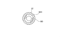
- FIG. 3 is a view of the configuration of FIG. 2 taken along the line II-II and viewed in the direction of the arrow.
- the lens unit LU ′ of the comparative example shown in FIG. 1 includes a first lens L1, a second lens L2, and an annular light shielding member SH1 disposed between the first lens L1 and the second lens L2. Has no filler.
- the outer periphery of the light shielding member SH1 is disposed inside the outer periphery of the first lens L1 or the second lens L2, and the flange portion FL1 of the first lens L1 and the second lens L1 are disposed on the outer periphery of the light shielding member SH1.
- the flange portions FL2 of the lens L2 are in contact with each other.
- the light-impermeable filler BD is filled and solidified between the outer periphery of the light shielding member SH1 and the outer periphery of the first lens L1 and the second lens L2.
- the filler BD is in contact with the entire outer periphery of the light shielding member SH1, and on the entire outer periphery of the first lens L1 and the second lens L2. It is in contact. If this condition is satisfied, the filling member BD may protrude inward from the outer periphery of the light shielding member SH1.
- the filling member BD does not protrude from the inner periphery to the inner side of the light shielding member SH1. This is because if it protrudes inside, for example, when used as an aperture stop, the function of the light shielding member SH1 may not be exhibited.
- the light when external light OL enters from the outside, as shown in FIG. 2, the light is reflected on the image side surface of the first lens L1, reflected on the outer periphery of the lens unit LU, and then the outer periphery of the light shielding member SH1. Since the light is shielded by the filler BD filled between the first lens L1 and the outer periphery of the second lens L2, it does not pass to the second lens L2 side, and the ghost suppression effect is high.
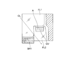
- FIG. 4 is an enlarged view showing the periphery of a lens unit corresponding to the prior art of Patent Document 2.
- the groove GV is provided on the entire circumference on the upper surface of the flange portion FL2 of the lens, and the fluid A is provided therein. In this way, the fluid A is poured into the groove GV.
- the number of man-hours increases by one, and the filling amount must be controlled so that the fluid A does not overflow, which is troublesome and increases the manufacturing cost.
- the present invention as long as it does not protrude from the inner periphery to the inner side of the light shielding member SH1, there is no problem in yield even if a large amount of filler BD is applied, and man-hours can be reduced. In some cases, there is no functional problem even if it protrudes from the outer periphery of the lens.
- the flange portion FL2 provided with the groove GV is thinner than the other portions, so that it is difficult to mold with a lens that is thinned to the limit. Furthermore, if the groove GV is further formed in the place where the lens is thinned, the strength of that portion is further reduced. Further, since the transfer portion of the mold for transferring the groove GV is convex, there are problems that it takes a long time for processing, and stress on the molding mold is concentrated to shorten the life of the mold. On the other hand, according to the present invention, there is no need to provide a groove for filling the filler, and there is an advantage that the manufacturing cost of the mold is reduced, the mold life is extended, and the lens strength is increased.
- the filler BD is used as the light shielding member. Since it is in contact with the entire outer periphery of SH1, there is no possibility that external light OL will pass.
- the lens unit according to claim 2 is characterized in that, in the invention according to claim 1, the filler is an adhesive that adheres the first lens and the second lens.
- the adhesive can have a light shielding function, the number of man-hours can be further reduced.
- the lens unit according to claim 3 is characterized in that, in the invention according to claim 2, the adhesive is based on an energy curable adhesive and is a mixture of carbon black or metal powder.
- the energy curable adhesive When energy curable adhesive is used, there is no need to worry about the curing time, and the handleability is excellent.
- the energy curable adhesive include a UV curable adhesive that is solidified by irradiation with UV light and a thermosetting adhesive that is cured by heating.
- a thermosetting adhesive that is cured by heating.
- a mixture of carbon and the like in a UV curable adhesive is hard to be cured due to its light shielding properties, but a thermosetting adhesive is preferable because it has never been said to be inhibited by light shielding properties.
- the three lenses when the three lenses are joined, even if the light shielding portions overlap, they can be cured by heating the whole.
- the lens unit according to claim 4 is the lens unit according to claim 3, wherein the energy curable adhesive is a UV curable adhesive, and the first curable adhesive is cured when the UV curable adhesive is cured.
- the UV curable adhesive applied between the second lens and the second lens is irradiated with UV light from both sides in the optical axis direction.
- a mixture of carbon and the like in a UV curable adhesive is difficult to cure due to its light shielding properties, but can be effectively cured by irradiating UV light from both sides in the optical axis direction. .
- the lens unit according to claim 5 is characterized in that, in the invention according to claim 3, the energy curable adhesive is a thermosetting adhesive.
- a thermosetting adhesive is effective when UV light is difficult to reach between lenses.
- a lens unit according to a fifth aspect of the present invention is the lens unit according to any one of the first to fourth aspects, wherein the first lens and the second lens are kept at a predetermined distance while the first lens is maintained. And the second lens are bonded together.
- the thickness of the filler in between is close to zero. Therefore, by keeping the distance between the first lens and the second lens at a predetermined distance, the thickness of the filler filled between the first lens and the second lens can be increased to the extent that light is not transmitted.
- a lens unit according to a sixth aspect of the present invention is the lens unit according to any one of the first to fifth aspects, wherein the first lens array has a plurality of the first lenses and the second has a plurality of the second lenses.
- a lens array is bonded to the first lens and the second lens facing each other with the light shielding member and the filler interposed therebetween, and then cut for each of the first lens and the second lens. It is characterized by becoming.
- a lens unit according to a seventh aspect is the lens unit according to any one of the first to sixth aspects, wherein the third lens, another annular member disposed between the second lens and the third lens is provided.
- a light shielding member, and an outer periphery of the another light shielding member is disposed on an inner side of an outer periphery of the second lens or the third lens, and the outer periphery of the another light shielding member and the second lens
- the filler is filled between the lens or the outer periphery of the third lens and solidified.
- FIG. It is a figure which shows the process of shape
- FIG. 5 is a diagram schematically showing steps (a) to (e) for forming a lens unit LU by bonding a first glass lens array LA1 and a second glass lens array LA1 ′. It is the figure which cut
- FIG. 4 is a diagram schematically showing (a) to (i) in which a lens unit LU is formed by bonding a first glass lens array LA1, a second glass lens array LA1 ′, and a third glass lens array LA1 ′′.
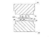
- FIGS. 5 to 8 are diagrams showing a process of molding the lens array used in the present embodiment using a molding die.
- the circumference of each optical surface transfer surface 12 is a circular step portion 13 that protrudes one step from the lower surface 11.
- the upper mold 10 can be made of a hard and brittle material that can withstand glass molding, for example, a material such as a cemented carbide or silicon carbide. The same applies to the lower mold 20 described below.
- a substantially square land portion 22 is formed on the upper surface 21 of the lower mold 20, and four optical surface transfer surfaces 24 are formed in a concave manner on the flat upper surface 23 of the land portion 22 in two rows and two columns.
- flat portions 25 are formed to be inclined at a predetermined angle with respect to the optical axis of the optical surface transfer surface 24.
- the adjacent flat portions 25 are connected by a corner portion 26 (see FIG. 8) so that the axes are orthogonal to each other.
- Such a flat portion 25 can be formed with high accuracy by machining using a milling cutter or the like.
- a concave portion for transferring a mark indicating the direction may be provided on the land portion 22.
- an identification number for the optical transfer surface 24 may be provided at a place other than the optical transfer surface 24.
- the multi-surface optical surface transfer surface processing of the mold can be formed by grinding using a grindstone using an ultra-precision processing machine. After grinding, in order to remove grinding marks, a polishing process can be performed to finish the mirror surface. The positional accuracy of the optical surface can be confirmed by using a three-dimensional measuring device to measure the distance from the flat surface portion 25 and the distance between the optical surface transfer surfaces 24 and to be within the determined standard.
- any of the following methods can be taken.
- a preform formed in an approximate shape of a lens portion in advance such as conventional glass lens molding
- a glass lens array is formed, and in particular, a lens part and a non-lens part (between a plurality of lens parts).
- the portion of the intermediate body is preferably a method of (2) that can take a large difference in core thickness, and is not a method of dropping glass individually on each molding surface, That is, it is preferable to collectively drop molten glass droplets having a volume sufficiently filled in at least two molding surfaces.
- the dropping position is more preferably a method of dropping at a position equidistant from a plurality of molding surfaces scheduled to be filled.
- the lower mold 20 is positioned below a platinum nozzle NZ communicating with a storage unit (not shown) in which glass is heated and melted. Drops of glass GL melted from the platinum nozzle NZ are collectively dropped onto the upper surface 21 toward a position equidistant from the plurality of optical surface transfer surfaces 24. In such a state, since the viscosity of the glass GL is low, the dropped glass GL spreads on the upper surface 21 so as to wrap around the land portion 22, and the shape of the land portion 22 is transferred.
- the amount of droplets of a relatively large glass GL passing through the four small holes is adjusted and then decomposed into four small droplets. At the same time, it is supplied onto the upper surface 21.
- dripping liquid molten glass since it becomes easy to produce air accumulation between each shaping
- the lower mold 20 is brought close to and aligned with the upper mold 10 to a position facing the lower side of the upper mold 10 in FIG. Further, as shown in FIG. 6, molding is performed by bringing the upper mold 10 and the lower mold 20 close to each other using a guide (not shown). As a result, the optical surface transfer surface 12 and the circular step portion 13 of the upper mold 10 are transferred to the upper surface of the flattened glass GL, and the shape of the land portion 22 of the lower mold 20 is transferred to the lower surface thereof. Is done. At this time, the lower surface 11 of the upper mold 10 and the upper surface 21 of the lower mold 20 are held so as to be spaced apart in parallel by a predetermined distance to cool the glass GL. The glass GL solidifies in a state in which the glass GL wraps around and transfers the flat portion 25.
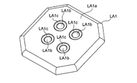
- FIG. 9 is a perspective view of the front side of the glass lens array LA1
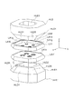
- FIG. 10 is a perspective view of the back side.
- FIG. 11 is a cross-sectional view including the optical axis of the glass lens array LA1.
- the glass lens array LA1 is a thin square plate as a whole, and is formed on the surface LA1a, which is a high-accuracy plane transferred by the lower surface 11 of the upper mold 10, and on the surface LA1a. It has four concave optical surfaces LA1b transferred and formed by the surface transfer surface 12, and a shallow circular groove LA1c transferred by the circular step portion 13 around the concave optical surface LA1b.
- This circular groove LA1c is for accommodating, for example, the light shielding member SH (see FIG. 2).
- the glass lens array LA1 includes a bottom surface LA1d that is a high-precision flat surface that is transferred and molded by the upper surface 23 of the land portion 22 of the lower mold 20, and four protrusions that are transferred and formed by the optical surface transfer surface 24 on the bottom surface LA1d. And a first flat surface LA1f and a corner connecting portion LA1g that are transfer-molded by the flat surface portion 25 and the corner portion 26 of the land portion 22. Note that LA1h is a mark indicating the direction simultaneously transferred. An inner peripheral surface is constituted by the first plane LA1f and the corner connecting portion LA1g.
- the first plane LA1f is inclined at 10 ° to 60 ° (here 45 °) with respect to the optical axis OA of the optical surface.
- FIG. 12 is a cross-sectional view showing holders HLD and HLD ′ for holding the rear surfaces of the glass lens arrays LA1 and LA1 ′
- FIG. 13 is a perspective view.
- the holders HLD and HLD ' are mounted on XYZ tables TBL and TBL' (schematically illustrated) that are movable in three dimensions.
- the direction along the optical surface is defined as the Z direction
- the directions orthogonal to the Z direction are defined as the X direction and the Y direction.
- Each rectangular cylindrical holder HLD, HLD ' has a tapered surface HLD1 on the outer periphery on the holding side and an end surface HLD2 intersecting with the tapered surface HLD1.
- Four tapered surfaces HLD1 as the second plane are provided corresponding to the first plane LA1f of the glass lens arrays LA1 and LA1 ′, and are inclined at 45 ° with respect to the axis of the central opening HLD3 of the holders HLD and HLD ′.
- the central opening HLD3 has a size that surrounds the optical surface LA1e of the glass lens arrays LA1 and LA1 '. Therefore, the end surface HLD2 can abut on the bottom surface LA1d of the glass lens arrays LA1 and LA1'.
- the back side of the central opening HLD3 is connected to the negative pressure source P.
- the adjacent tapered surfaces HLD1 are connected by a corner tapered surface HLD5.
- the outer peripheral surface is constituted by the tapered surface HLD1 and the corner tapered surface HLD5. It is preferable to form a relief E of the mark LA1h between the end face HLD2 and the corner taper face HLD5.
- the holders HLD and HLD ' are preferably made of a stainless steel material and subjected to quenching to suppress wear and shape change, and the hardness is set to HRC56 or higher.
- the interval between the opposing tapered surfaces HLD1 is preferably determined by calculating the amount of contraction during lens array molding and feeding it back.
- the end face HLD2 comes into contact with the bottom surface LA1d of the first glass lens array LA1, so that the inside of the central opening HLD3 is in this state. Is made negative pressure, the first glass lens array LA1 is sucked and held by the holder HLD.
- the first plane LA1f of the first glass lens array LA1 is opposed to or in contact with the tapered surface HLD1 of the holder HLD with a clearance ⁇ of 10 ⁇ m or less (for example, 2 ⁇ m) (see FIG. 10).
- the corner connecting portion LA1g is opposed to the corner taper surface HLD5 with more clearance.
- the first glass lens array LA1 does not rotate any more with respect to the holder HLD.
- the tapered surface HLD1 is regulated by the opposing first plane LA1f, so that the first glass lens array LA1 does not move further relative to the holder HLD. That is, by holding the first glass lens array LA1 by the holder HLD, the first glass lens array LA1 can be accurately positioned with respect to the holder HLD. By the same operation, the holder HLD ′ can hold the second glass lens array LA1 ′ with high accuracy.
- the glass lens arrays LA1 and LA1 ′ held by the holders HLD and HLD ′ can be positioned with high accuracy facing each other. Thereby, all four optical surfaces can be aligned with high accuracy.
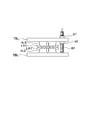
- FIG. 14 is a schematic view of an apparatus for maintaining the holder HLD holding the first glass lens array LA1 and the holder HLD 'holding the second glass lens array LA1' at a predetermined interval.
- a bolt BT is screwed to a movable XYZ table TBL that can move in the vertical direction to which the holder HLD is fixed.
- the lower end of the bolt BT is in contact with the upper surface of the fixed XYZ table TBL 'to which the holder HLD' is fixed.
- the lock nut NT fixes the bolt BT having a protruding amount set to the moving XYZ table TBL. As described above, the film thickness of the light-shielding adhesive BD (described later) can be managed.
- FIG. 15 is a schematic diagram of steps (a) to (e) in which the first glass lens array LA1 and the second glass lens array LA1 'are bonded together to form the lens unit LU.
- the light shielding member SH1 is made of 304 type stainless steel that is colored black.
- FIG. 15A four donut plate-shaped light shielding members SH1 are arranged in accordance with the lens portions of the second glass lens array LA1 'held by a holder (not shown).
- the second glass lens array LA1 ' has four shallow recesses (LA1c in FIG. 11) having a tapered inner periphery, the light shielding member SH1 can be centered.
- the UV curable light-blocking adhesive BD (for example, product name “World Rock” manufactured by Kyoritsu Chemical Industry Co., Ltd.) is applied to the surface SF2 of the second glass lens array LA1 ′.
- the surface SF1 of the first glass lens array LA1 accurately held by a holder (not shown) mounted on the moving stage, and the second glass lens array LA1 ′.
- the surface SF2 is opposed to the surface SF2 and is brought close to a predetermined interval (about 5 ⁇ m gap between lenses) using the apparatus shown in FIG.
- the light-shielding adhesive BD may be a thermosetting adhesive.
- UV light is irradiated from the lower surface side of the second glass lens array LA1 '.
- UV light may be irradiated from the upper surface side of the first glass lens array LA1.
- the light-shielding adhesive BD is solidified.
- FIG. 16 is a diagram of the state shown in FIG. 15 (d) cut along the XVI-XVI line and viewed in the optical axis direction.
- the light-shielding filler BD is in contact with the entire outer periphery of the four light-shielding members SH1.
- the glass lens arrays LA1 and LA1 ′ are positioned at dotted lines (FIG. 15E) as described later. Since the lens unit is cut at the same time, it is sufficient that the light-shielding filler BD is filled up to the cutting position. That is, the cutting position is the outer periphery of the lens unit.
- the lens array body IM12 held by the lower holder can be taken out by stopping and separating the suction of the upper holder.
- a lens unit LU as shown in FIG. 17 can be obtained by cutting the lens array body IM12 at the position of the dotted line by a dicing blade (not shown).
- the lens unit LU includes a first lens L1, a second lens L2, and a light shielding member SH1 disposed between the first lens L1 and the second lens L2, and the outer periphery of the light shielding member SH1 and the lens unit LU. Is filled with a light-shielding filler BD.
- a light-shielding filler BD As described above, when the flange portion FL1 of the first lens L1 and the flange portion FL2 of the second lens L2 are rectangular, extra portions are formed at the four corners. The effect is demonstrated.
- FIG. 18 is a schematic view of steps (a) to (i) in which the first glass lens array LA1, the second glass lens array LA1 ′, and the third glass lens array LA1 ′′ are bonded together to form the lens unit LU. is there.
- a third glass lens array LA1 ′′ is manufactured, and as shown in FIG. 18 (e), a third glass lens array in which four donut plate-shaped light shielding members SH2 are held by a holder (not shown). It is arranged according to the lens portion of LA1 ′′.
- the third glass lens array LA1 ′′ four shallow concave portions having a tapered inner periphery are formed, so that the light shielding member SH2 can be centered.
- an appropriate amount of UV curable light-shielding adhesive BD is applied to the surface SF3 of the third glass lens array LA1 ′′, and then the holder is placed as shown in FIG. 18 (g).
- the lens array IM12 is opposed to the surface SF3 of the third glass lens array LA1 ′′ held with high precision (not shown), and is brought close to a predetermined interval (about 5 ⁇ m gap between lenses) using the apparatus shown in FIG. .
- the suction of the upper holder is stopped and separated to remove the third glass lens array LA1 ′′ held by the lower holder. Therefore, by cutting the third glass lens array LA1 ′′ at the position of the dotted line with a dicing blade (not shown), it is possible to obtain a lens unit LU having a three-piece structure.
Landscapes
- Physics & Mathematics (AREA)
- General Physics & Mathematics (AREA)
- Optics & Photonics (AREA)
- Engineering & Computer Science (AREA)
- Chemical & Material Sciences (AREA)
- Manufacturing & Machinery (AREA)
- Materials Engineering (AREA)
- Organic Chemistry (AREA)
- Health & Medical Sciences (AREA)
- Toxicology (AREA)
- Lens Barrels (AREA)
- Optical Elements Other Than Lenses (AREA)
Description
(1)従来のガラスレンズ成形のような予めレンズ部の近似形状に形成されたプリフォームを金型の各成形面内に配置して、それらを加熱、冷却して成形する方法
(2)液状の溶融ガラスを成形面に上方から滴下し、それらを加熱することなく、冷却して成形する方法
ここではガラスレンズアレイを成形するという構成上、特にレンズ部と非レンズ部(複数のレンズ部間又は中間体の端部を形成する部分)との芯厚の差を大きく取る事ができる(2)の方法が好ましく、更に各成形面に個別にガラスを滴下する方法ではなく、大きなガラス滴、すなわち少なくとも2つの成形面に十分に充填される体積の溶融ガラス滴を一括滴下する方法が好ましい。また滴下位置は、充填を予定している複数の成形面から等距離の位置に滴下する方法がより好ましい。係る構成をとることにより、各成形面に充填されるガラス滴の時間差が小さくなり、成形されるレンズ形状の形状差、光学性能への悪影響が軽減される。勿論、当該時間差を考慮して各成形面に個別にガラス滴を同時に滴下しても同様な効果が得られるが、ガラスの小滴化は構成上装置が大型、複雑となるため、前者の方がより好ましい。
11 下面
12 光学面転写面
13 円形段部
20 下金型
21 上面
22 ランド部
23 上面
24 光学面転写面
25 平面部
26 コーナー部
40 鏡枠
40a フランジ部
40b 開口
40c 内周面
LU レンズユニット
FL1 矩形板状フランジ
FL2 矩形板状フランジ
LA1 第1ガラスレンズアレイ
LA1’ 第2ガラスレンズアレイ
LA1” 第3ガラスレンズアレイ
LA1a 表面
LA1b 凹状光学面
LA1c 円形溝
LA1d 底面
LA1e 光学面
LA1e 凸状光学面
LA1f 平面
LA1g コーナー連結部
IM12 レンズアレイ体
HLD、HLD’ ホルダ
HLD1 テーパ面
HLD2 端面
HLD3 中央開口
HLD4 逃げ部
HLD5 コーナテーパ面
NZ 白金ノズル
SH1,SH2 遮光部材
Claims (8)
- 第1のレンズと、第2のレンズと、前記第1のレンズと前記第2のレンズ間に配置された環状の遮光部材とを有し、
前記遮光部材の外周は、前記第1のレンズ又は前記第2のレンズの外周より内側に配置されており、前記遮光部材の外周と、前記第1のレンズ又は前記第2のレンズの外周との間にわたって、光を不透過な充填剤を充填し、固化させたことを特徴とするレンズユニット。 - 前記充填剤は、前記第1のレンズと前記第2のレンズを接着する接着剤であることを特徴とする請求項1に記載のレンズユニット。
- 前記接着剤は、エネルギー硬化性接着剤をベースとし、カーボンブラック又は金属粉を混ぜたものを用いることを特徴とする請求項2に記載のレンズユニット。
- 前記エネルギー硬化性接着剤は、UV硬化性接着剤であり、前記UV硬化性接着剤を硬化させるときは、前記第1のレンズと前記第2のレンズの間に付与したUV硬化性接着剤に対して、光軸方向両側からUV光を照射するようになっていることを特徴とする請求項3に記載のレンズユニット。
- 前記エネルギー硬化性接着剤は、熱硬化性接着剤であることを特徴とする請求項3に記載のレンズユニット。
- 前記第1のレンズと前記第2のレンズの間隔を所定間隔に保持しながら、前記第1のレンズと前記第2のレンズを接着するようになっていることを特徴とする請求項1~5のいずれかに記載のレンズユニット。
- 複数の前記第1のレンズを有する第1レンズアレイと、複数の前記第2のレンズを有する第2レンズアレイとを、対向する前記第1のレンズと前記第2のレンズの間に前記遮光部材と前記充填剤を介在させつつ貼り合わせ、その後前記第1のレンズと前記第2のレンズ毎に切断してなることを特徴とする請求項1~6のいずれかに記載のレンズユニット。
- 第3のレンズと、前記第2のレンズと前記第3のレンズ間に配置された環状の別の遮光部材とを有し、前記別の遮光部材の外周は、前記第2のレンズ又は前記第3のレンズの外周より内側に配置されており、前記別の遮光部材の外周と、前記第2のレンズ又は前記第3のレンズの外周との間にわたって、前記充填剤を充填し、固化させたことを特徴とする請求項1~7のいずれかに記載のレンズユニット。
Priority Applications (2)
| Application Number | Priority Date | Filing Date | Title |
|---|---|---|---|
| US14/394,001 US20150077839A1 (en) | 2012-04-13 | 2013-04-10 | Lens Unit |
| CN201380019129.0A CN104204886A (zh) | 2012-04-13 | 2013-04-10 | 透镜单元 |
Applications Claiming Priority (2)
| Application Number | Priority Date | Filing Date | Title |
|---|---|---|---|
| JP2012091544 | 2012-04-13 | ||
| JP2012-091544 | 2012-04-13 |
Publications (1)
| Publication Number | Publication Date |
|---|---|
| WO2013154121A1 true WO2013154121A1 (ja) | 2013-10-17 |
Family
ID=49327681
Family Applications (1)
| Application Number | Title | Priority Date | Filing Date |
|---|---|---|---|
| PCT/JP2013/060780 Ceased WO2013154121A1 (ja) | 2012-04-13 | 2013-04-10 | レンズユニット |
Country Status (4)
| Country | Link |
|---|---|
| US (1) | US20150077839A1 (ja) |
| JP (1) | JPWO2013154121A1 (ja) |
| CN (1) | CN104204886A (ja) |
| WO (1) | WO2013154121A1 (ja) |
Cited By (4)
| Publication number | Priority date | Publication date | Assignee | Title |
|---|---|---|---|---|
| JP2016078328A (ja) * | 2014-10-16 | 2016-05-16 | 富士フイルム株式会社 | レンズの製造方法 |
| JP2017116690A (ja) * | 2015-12-24 | 2017-06-29 | セイコーエプソン株式会社 | 虚像表示装置 |
| JP2019090849A (ja) * | 2017-11-10 | 2019-06-13 | カンタツ株式会社 | 光学素子及び撮像レンズ |
| US20220317344A1 (en) * | 2021-03-31 | 2022-10-06 | Genius Electronic Optical (Xiamen) Co., Ltd. | Light-shielding element and optical imaging lens applying the same |
Families Citing this family (7)
| Publication number | Priority date | Publication date | Assignee | Title |
|---|---|---|---|---|
| US9981844B2 (en) * | 2012-03-08 | 2018-05-29 | Infineon Technologies Ag | Method of manufacturing semiconductor device with glass pieces |
| TWI614518B (zh) * | 2016-05-09 | 2018-02-11 | 大立光電股份有限公司 | 成像鏡頭及電子裝置 |
| CN106802460B (zh) * | 2016-10-25 | 2019-01-08 | 瑞声科技(新加坡)有限公司 | 镜片、镜片的加工方法及镜头模组 |
| JP6964050B2 (ja) * | 2018-07-20 | 2021-11-10 | オリンパス株式会社 | 光学素子の製造方法 |
| CN208636492U (zh) * | 2018-08-04 | 2019-03-22 | 瑞声科技(新加坡)有限公司 | 一种镜头模组 |
| US20200400952A1 (en) * | 2019-06-18 | 2020-12-24 | Facebook Technologies, Llc | Lens with internal aperture |
| US11850811B1 (en) | 2019-06-18 | 2023-12-26 | Meta Platforms Technologies, Llc | Monolithic compound lens |
Citations (2)
| Publication number | Priority date | Publication date | Assignee | Title |
|---|---|---|---|---|
| JPS62184079A (ja) * | 1986-02-07 | 1987-08-12 | Olympus Optical Co Ltd | 光学部品の保持装置 |
| JP2011232614A (ja) * | 2010-04-28 | 2011-11-17 | Konica Minolta Opto Inc | 撮像レンズの製造方法 |
Family Cites Families (9)
| Publication number | Priority date | Publication date | Assignee | Title |
|---|---|---|---|---|
| JP2003204053A (ja) * | 2001-03-05 | 2003-07-18 | Canon Inc | 撮像モジュール及び該撮像モジュールの製造方法、デジタルカメラ |
| US7457052B2 (en) * | 2004-08-09 | 2008-11-25 | Hitachi Maxwell, Ltd. | Light shield sheet, optical apparatus, and method of manufacturing light shield sheet |
| US20060139772A1 (en) * | 2004-12-27 | 2006-06-29 | Canon Kabushiki Kaisha | Method of fixing optical member and optical unit |
| CN101487951A (zh) * | 2005-01-31 | 2009-07-22 | 凸版印刷株式会社 | 光学片和使用它的背光源单元以及显示器 |
| US7358483B2 (en) * | 2005-06-30 | 2008-04-15 | Konica Minolta Holdings, Inc. | Method of fixing an optical element and method of manufacturing optical module including the use of a light transmissive loading jig |
| US8300328B2 (en) * | 2007-07-03 | 2012-10-30 | Optomecha Co., Ltd. | Lens unit composed of different materials and camera module and method for manufacturing the same |
| JP2009124515A (ja) * | 2007-11-15 | 2009-06-04 | Sharp Corp | 撮像モジュールおよびその製造方法、電子情報機器 |
| JP4577584B2 (ja) * | 2008-01-23 | 2010-11-10 | ソニー株式会社 | レンズ鏡筒及び撮像ユニット |
| WO2009125640A1 (ja) * | 2008-04-09 | 2009-10-15 | 日立マクセル株式会社 | レンズユニット、カメラモジュール、及びレンズユニットの製造方法 |
-
2013
- 2013-04-10 JP JP2014510179A patent/JPWO2013154121A1/ja active Pending
- 2013-04-10 CN CN201380019129.0A patent/CN104204886A/zh active Pending
- 2013-04-10 US US14/394,001 patent/US20150077839A1/en not_active Abandoned
- 2013-04-10 WO PCT/JP2013/060780 patent/WO2013154121A1/ja not_active Ceased
Patent Citations (2)
| Publication number | Priority date | Publication date | Assignee | Title |
|---|---|---|---|---|
| JPS62184079A (ja) * | 1986-02-07 | 1987-08-12 | Olympus Optical Co Ltd | 光学部品の保持装置 |
| JP2011232614A (ja) * | 2010-04-28 | 2011-11-17 | Konica Minolta Opto Inc | 撮像レンズの製造方法 |
Cited By (5)
| Publication number | Priority date | Publication date | Assignee | Title |
|---|---|---|---|---|
| JP2016078328A (ja) * | 2014-10-16 | 2016-05-16 | 富士フイルム株式会社 | レンズの製造方法 |
| JP2017116690A (ja) * | 2015-12-24 | 2017-06-29 | セイコーエプソン株式会社 | 虚像表示装置 |
| JP2019090849A (ja) * | 2017-11-10 | 2019-06-13 | カンタツ株式会社 | 光学素子及び撮像レンズ |
| US20220317344A1 (en) * | 2021-03-31 | 2022-10-06 | Genius Electronic Optical (Xiamen) Co., Ltd. | Light-shielding element and optical imaging lens applying the same |
| US12078822B2 (en) * | 2021-03-31 | 2024-09-03 | Genius Electronic Optical (Xiamen) Co., Ltd. | Light-shielding element and optical imaging lens applying the same |
Also Published As
| Publication number | Publication date |
|---|---|
| US20150077839A1 (en) | 2015-03-19 |
| CN104204886A (zh) | 2014-12-10 |
| JPWO2013154121A1 (ja) | 2015-12-17 |
Similar Documents
| Publication | Publication Date | Title |
|---|---|---|
| WO2013154121A1 (ja) | レンズユニット | |
| EP3748430A1 (en) | Camera module | |
| TWI617430B (zh) | 製造微透鏡之方法及裝置 | |
| JP5812521B2 (ja) | 複眼ユニット | |
| US20130194676A1 (en) | Glass Lens | |
| US20120045619A1 (en) | Substrate provided with optical structure and optical element using the same | |
| CN102687051A (zh) | 摄像透镜单元 | |
| JP2009204752A (ja) | 複合レンズ | |
| AU2013202052A1 (en) | Lens plate for wafer-level camera and method of manufacturing same | |
| KR101493156B1 (ko) | 아포다이저 제조 방법 및 광학 모듈 | |
| CN103080779B (zh) | 用于制造透镜晶片的冲模工具、设备和方法 | |
| JP5673820B2 (ja) | レンズユニットの製造方法 | |
| TWI495559B (zh) | 用以製作一透鏡晶圓之方法及裝置 | |
| US20110063730A1 (en) | Disk-shaped optical lens array and manufacturing method thereof | |
| JP6473389B2 (ja) | レンズ部材、レンズ部材の製造方法、通信モジュール、レンズアレイおよび光源モジュール | |
| US9151925B2 (en) | Image pickup lens unit and method for manufacturing image pickup lens unit | |
| JP5716958B2 (ja) | レンズユニットの製造方法 | |
| JP6409870B2 (ja) | 光学素子の成形方法、成形型、及び光学素子 | |
| JP3154933U (ja) | スタックレンズモジュールの位置決めレンズホルダー | |
| JP2011232614A (ja) | 撮像レンズの製造方法 | |
| EP3770663B1 (en) | Lens system, method for manufacturing space ring, and method for assembling lens system | |
| TWI374120B (en) | The forming device of molding glasses | |
| KR20100050042A (ko) | 마이크로 렌즈용 마스터 및 마이크로 렌즈 제조방법 |
Legal Events
| Date | Code | Title | Description |
|---|---|---|---|
| 121 | Ep: the epo has been informed by wipo that ep was designated in this application |
Ref document number: 13775752 Country of ref document: EP Kind code of ref document: A1 |
|
| ENP | Entry into the national phase |
Ref document number: 2014510179 Country of ref document: JP Kind code of ref document: A |
|
| WWE | Wipo information: entry into national phase |
Ref document number: 14394001 Country of ref document: US |
|
| NENP | Non-entry into the national phase |
Ref country code: DE |
|
| 122 | Ep: pct application non-entry in european phase |
Ref document number: 13775752 Country of ref document: EP Kind code of ref document: A1 |