WO2013154019A1 - 撮像装置 - Google Patents
撮像装置 Download PDFInfo
- Publication number
- WO2013154019A1 WO2013154019A1 PCT/JP2013/060313 JP2013060313W WO2013154019A1 WO 2013154019 A1 WO2013154019 A1 WO 2013154019A1 JP 2013060313 W JP2013060313 W JP 2013060313W WO 2013154019 A1 WO2013154019 A1 WO 2013154019A1
- Authority
- WO
- WIPO (PCT)
- Prior art keywords
- image
- image data
- control unit
- cpu
- image quality
- Prior art date
- Legal status (The legal status is an assumption and is not a legal conclusion. Google has not performed a legal analysis and makes no representation as to the accuracy of the status listed.)
- Ceased
Links
Images




Classifications
-
- H—ELECTRICITY
- H04—ELECTRIC COMMUNICATION TECHNIQUE
- H04N—PICTORIAL COMMUNICATION, e.g. TELEVISION
- H04N23/00—Cameras or camera modules comprising electronic image sensors; Control thereof
- H04N23/80—Camera processing pipelines; Components thereof
-
- H—ELECTRICITY
- H04—ELECTRIC COMMUNICATION TECHNIQUE
- H04N—PICTORIAL COMMUNICATION, e.g. TELEVISION
- H04N23/00—Cameras or camera modules comprising electronic image sensors; Control thereof
- H04N23/60—Control of cameras or camera modules
- H04N23/63—Control of cameras or camera modules by using electronic viewfinders
- H04N23/631—Graphical user interfaces [GUI] specially adapted for controlling image capture or setting capture parameters
-
- H—ELECTRICITY
- H04—ELECTRIC COMMUNICATION TECHNIQUE
- H04N—PICTORIAL COMMUNICATION, e.g. TELEVISION
- H04N23/00—Cameras or camera modules comprising electronic image sensors; Control thereof
- H04N23/95—Computational photography systems, e.g. light-field imaging systems
- H04N23/951—Computational photography systems, e.g. light-field imaging systems by using two or more images to influence resolution, frame rate or aspect ratio
-
- H—ELECTRICITY
- H04—ELECTRIC COMMUNICATION TECHNIQUE
- H04N—PICTORIAL COMMUNICATION, e.g. TELEVISION
- H04N23/00—Cameras or camera modules comprising electronic image sensors; Control thereof
- H04N23/60—Control of cameras or camera modules
- H04N23/63—Control of cameras or camera modules by using electronic viewfinders
Definitions
- the present invention relates to an imaging device or the like that can generate a plurality of image data with different image quality.
- Japanese Patent Application Laid-Open No. 2007-151189 describes that an image pickup apparatus having a small display device can generate image data having a plurality of different image quality.
- image data with flat image quality is suitable for various image processing (post-processing) performed by a video editing device, but is suitable for viewing because it appears as flat image quality with reduced contrast and sharpness. There is no problem. Such a problem is a problem that occurs when image data with flat image quality is viewed on either the display device of the imaging apparatus or the display device of the external apparatus.
- an imaging apparatus uses, instead of flat image quality data suitable for a predetermined post process, image data having an image quality after a predetermined post process is applied to a display device of an external device. Can be displayed.
- an imaging apparatus externally outputs image data of image quality after a predetermined post process is applied from the imaging apparatus instead of flat image quality data suitable for the predetermined post process. Can be output.
- the imaging apparatus can display image data of image quality after a predetermined post process is applied to at least one of the display device of the imaging apparatus and the display device of the external apparatus. it can.
- an imaging apparatus outputs at least one of a plurality of external output units to externally output image data of image quality after a predetermined post process is applied from the imaging apparatus.
- the imaging apparatus includes: an imaging unit that generates first image data using an imaging element; and the first image data so that the image quality of the second image data is flat.
- Image processing means for generating the second image data from the image data, and adjusting the image quality of the second image data to be a predetermined image quality, thereby converting the second image data into the third image data.
- an output unit for outputting the third image data to an external device instead of the second image data when a predetermined condition is satisfied.
- FIG. 2 is a block diagram for explaining components included in the imaging apparatus 100 according to the first embodiment.
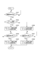
- 6 is a flowchart for explaining a moving image shooting process A1 performed by the imaging apparatus 100 according to the first embodiment.
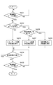
- 6 is a flowchart for explaining a moving image recording process B1 performed by the imaging apparatus 100 according to the first embodiment.
- 6 is a flowchart for explaining a moving image display process C1 performed by the imaging apparatus 100 according to the first embodiment.
- 6 is a flowchart for explaining a moving image output process D1 performed by the imaging apparatus 100 according to the first embodiment.
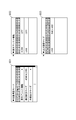
- 6 is a diagram for describing an example of a setting menu included in the imaging apparatus 100 according to Embodiment 1.
- FIG. 6 is a flowchart for explaining a moving image output process D2 performed by the imaging apparatus 100 according to the first embodiment.
- FIG. 1 is a block diagram for explaining components included in the imaging apparatus 100 according to the first embodiment.
- the imaging device 100 may be any device as long as it operates as a digital camera. Therefore, the imaging device 100 may be a device that operates as a camera-equipped mobile phone. Further, the imaging device 100 may be a device that operates as a computer with a camera.
- the imaging apparatus 100 includes an imaging unit 101, a lens unit 101a, a first image processing unit 102, a second image processing unit 103, an image quality adjustment unit 104, a recording control unit 105, a display control unit 106, and a display device 107.
- the imaging apparatus 100 further includes an HDMI control unit 108, an HDMI connector 108a, a USB control unit 109, a USB connector 109a, a CPU 111, a memory A 110, a UI unit 112, a memory B 113, and an internal bus 114.
- the imaging apparatus 100 further includes a power switch 112a, a moving image shooting mode button 112b, a start / stop button 112c, a menu button 112d, a cross button 112e, a set button 112f, and an information display button 112g.
- the imaging unit 101 captures an optical image via the lens unit 101a every predetermined time T1, and image data that generates image data of a predetermined format from the optical image captured by the imaging device every predetermined time T1. And a generation unit. Thereby, the imaging unit 101 can generate two or more continuous image data.
- the image data generated by the imaging unit 101 is referred to as “RAW image data”.
- Each RAW image data generated by the imaging unit 101 is supplied from the imaging unit 101 to each of the first image processing unit 102 and the second image processing unit 103.
- the image size (or horizontal and vertical resolution) of the RAW image data supplied from the imaging unit 101 to each of the first image processing unit 102 and the second image processing unit 103 is, for example, “4096 ⁇ 2160” or more.
- the predetermined time T1 may be any one of 1/24 seconds, 1/25 seconds, 1/30 seconds, 1/50 seconds, 1/60 seconds, 1/120 seconds, and the like.
- the lens unit 101a may be configured to be removable from the imaging unit 101.
- the first image processing unit 102 can perform various image processing including development processing.
- the first image processing unit 102 processes each RAW image data supplied from the imaging unit 101 using the image processing parameter information GP1.
- the image processing parameter information GP1 includes various parameters that can be set by the user.
- the image processing parameter information GP1 includes parameters relating to white balance, color interpolation, color correction, gamma conversion, edge enhancement, resolution, and the like.
- the initial setting of the image processing parameter information GP1 is set so as to generate image data with standard image quality.
- standard quality image data is, for example, ITU-R BT. 709 is image data processed so as to appear as an image conforming to the 709 standard.
- the standard image quality image data generated by the first image processing unit 102 is supplied from the first image processing unit 102 to each of the recording control unit 105, the display control unit 106, the HDMI control unit 108, and the USB control unit 109.
- the image size (or horizontal and vertical resolution) of the standard-quality image data supplied from the first image processing unit 102 to the recording control unit 105 is, for example, “4096 ⁇ 2160”, “1920 ⁇ 1080”, and “ 1280 ⁇ 720 ”.
- the image size (or horizontal and vertical resolution) of the standard image quality data supplied from the first image processing unit 102 to the display control unit 106 is, for example, “720 ⁇ 480”.
- the image size (or horizontal and vertical resolution) of standard image quality data supplied from the first image processing unit 102 to the HDMI control unit 108 is, for example, “1920 ⁇ 1080”, “1280 ⁇ 720”, and “640”. ⁇ 480 ”.
- the image size (or horizontal and vertical resolution) of standard image quality data supplied from the first image processing unit 102 to the USB control unit 109 is, for example, “1920 ⁇ 1080”, “1280 ⁇ 720”, and “640”. ⁇ 480 ”.
- the second image processing unit 103 can perform various image processing including development processing.
- the second image processing unit 103 converts each RAW image data into image data with flat image quality by processing each RAW image data supplied from the imaging unit 101 using the image processing parameter information GP2.
- the image processing parameter information GP2 includes various parameters for generating flat image quality image data.
- the image processing parameter information GP2 includes parameters relating to white balance, color interpolation, color correction, gamma conversion, edge enhancement, resolution, and the like.
- flat image quality image data has a wide dynamic range and image quality with reduced contrast and sharpness.
- the flat image quality image data is suitable for various image processing (post-process) performed by the moving image editing apparatus.
- the flat image quality image data generated by the second image processing unit 103 is sent from the second image processing unit 103 to the image quality adjustment unit 104, the recording control unit 105, the display control unit 106, the HDMI control unit 108, and the USB control unit. 109 is supplied.
- the first image processing unit 102 and the second image processing unit 103 may be configured as two different image processing units or may be configured as one image processing unit.
- the image size (or horizontal and vertical resolution) of the flat image quality image data supplied from the second image processing unit 103 to the recording control unit 105 is, for example, “4096 ⁇ 2160”, “1920 ⁇ 1080” and One of “1280 ⁇ 720”.
- the image size (or horizontal and vertical resolution) of the flat image quality image data supplied from the second image processing unit 103 to the image quality adjustment unit 104 is, for example, “1920 ⁇ 1080”, “1280 ⁇ 720”, and “ 640 ⁇ 480 ”.
- the image size (or horizontal and vertical resolution) of the flat image quality image data supplied from the second image processing unit 103 to the display control unit 106 is, for example, “720 ⁇ 480”.
- the image size (or horizontal and vertical resolution) of the flat image quality image data supplied from the second image processing unit 103 to the HDMI control unit 108 is, for example, “1920 ⁇ 1080”, “1280 ⁇ 720”, and “ 640 ⁇ 480 ”.
- the image size (or horizontal and vertical resolution) of the flat image quality image data supplied from the second image processing unit 103 to the USB control unit 109 is, for example, “1920 ⁇ 1080”, “1280 ⁇ 720”, and “ 640 ⁇ 480 ”.
- the image quality adjustment unit 104 can adjust the image quality of each image data supplied from the second image processing unit 103 to a predetermined image quality.
- the predetermined image quality is an image quality after a predetermined post process is applied to flat image quality image data.
- the predetermined image quality is a sharp image quality.
- the predetermined image quality may be determined so as to be the same as the image quality of the image data generated by the first image processing unit 102.
- image data after image quality adjustment In the first embodiment, image data whose image quality has been adjusted is, for example, ITU-R BT. A case in which the image data is adjusted so as to appear as an image in conformity with 709 will be described.
- the predetermined post process can be selected by the user from a plurality of post processes.
- the CPU 111 transmits information indicating the image quality corresponding to the post process selected by the user to the image quality adjustment unit 104. Receiving this information, the image quality adjustment unit 104 adjusts the image quality of each image data supplied from the second image processing unit 103 so that the image quality corresponds to the post process selected by the user.
- the image quality adjusted image data generated by the image quality adjustment unit 104 is supplied from the image quality adjustment unit 104 to each of the display control unit 106, the HDMI control unit 108, and the USB control unit 109.
- the image size (or horizontal and vertical resolution) of the image data after image quality adjustment supplied from the image quality adjustment unit 104 to the HDMI control unit 108 is, for example, “1920 ⁇ 1080”, “1280 ⁇ 720”, and “640 ⁇ 480”. Either.
- the image size (or horizontal and vertical resolution) of the image data after image quality adjustment supplied from the image quality adjustment unit 104 to the USB control unit 109 is, for example, “1920 ⁇ 1080”, “1280 ⁇ 720”, and “640 ⁇ 480”. Any of the above.
- the storage device 105a is a storage device having a flash memory, a memory card, a hard disk device, etc., and operates as a recording medium.
- the storage device 105 a may be a storage device that is removable from the imaging apparatus 100 or may be a storage device that is built in the imaging apparatus 100.
- the recording control unit 105 has a first function for recording each image data supplied from the first image processing unit 102 as moving image data in the storage device 105a. With this first function, the recording control unit 105 can record standard-quality image data as moving image data in the storage device 105a.
- the recording control unit 105 has a second function for recording each image data supplied from the second image processing unit 103 as moving image data in the storage device 105a. With this second function, the recording control unit 105 can record flat image quality image data as moving image data in the storage device 105a.
- the recording control unit 105 has a third function for reading moving image data designated by the user from the storage device 105a. Each image data included in the moving image data read from the storage device 105 a is supplied from the recording control unit 105 to the display control unit 106 and displayed on the display device 107.
- the display control unit 106 has a first function for causing the display device 107 to display an image corresponding to each image data supplied from the first image processing unit 102. With this first function, the display control unit 106 can cause the display device 107 to display an image corresponding to standard-quality image data.
- the display control unit 106 has a second function for causing the display device 107 to display an image corresponding to each image data supplied from the second image processing unit 103. With this second function, the display control unit 106 can display an image corresponding to flat image quality image data on the display device 107.
- the display control unit 106 has a third function for causing the display device 107 to display an image corresponding to each image data supplied from the image quality adjustment unit 104. With this third function, the display control unit 106 can cause the display device 107 to display an image corresponding to the image data whose image quality has been adjusted.
- the display device 107 includes a liquid crystal display device.
- the display device 107 may be configured to be removable from the imaging apparatus 100.
- the HDMI control unit 108 operates as an external output unit that conforms to the HDMI (High-Definition Multimedia Interface) standard.
- the HDMI control unit 108 has at least one HDMI connector 108a.
- the HDMI control unit 108 has a first function for outputting each image data supplied from the first image processing unit 102 to the external device EX1 as moving image data. With this first function, the HDMI control unit 108 can transmit standard-quality image data to the external device EX1.
- the HDMI control unit 108 has a second function for outputting each image data supplied from the second image processing unit 103 to the external device EX1 as moving image data. With this second function, the HDMI control unit 108 can transmit flat image quality image data to the external device EX1.
- the HDMI control unit 108 has a third function for outputting each image data supplied from the image quality adjustment unit 104 to the external device EX1 as moving image data. With this third function, the HDMI control unit 108 can transmit image data whose image quality has been adjusted to the external device EX1.
- the USB control unit 109 operates as an external output unit that conforms to the USB (Universal Serial Bus) standard.
- USB 2.0, USB 3.0, etc. are known as USB standards.
- the USB control unit 109 has at least one USB connector 109a.
- the USB control unit 109 has a first function for outputting each image data supplied from the first image processing unit 102 to the external device EX2 as moving image data. With this first function, the USB control unit 109 can transmit standard-quality image data to the external device EX2.
- the USB control unit 109 also has a second function for outputting each image data supplied from the second image processing unit 103 to the external device EX2 as moving image data. With this second function, the USB control unit 109 can transmit flat image quality image data to the external device EX2.
- the USB control unit 109 has a third function for outputting each image data supplied from the image quality adjustment unit 104 to the external device EX2 as moving image data. With this third function, the USB control unit 109 can transmit image data whose image quality has been adjusted to the external device EX2.
- the memory A110 stores a plurality of programs to be executed by the CPU 111.
- the plurality of programs stored in the memory A110 include programs Pg1 to Pg5 described later.
- a CPU (Central Processing Unit) 111 has a processor for controlling the imaging apparatus 100 using a plurality of programs stored in the memory A110.
- the imaging unit 101, the lens unit 101a, the first image processing unit 102, the second image processing unit 103, the image quality adjustment unit 104, the recording control unit 105, the display control unit 106, and the display device 107 are controlled by the CPU 111.
- the HDMI control unit 108, the HDMI connector 108a, the USB control unit 109, the USB connector 109a, the memory A 110, the UI unit 112, and the memory B 113 are also controlled by the CPU 111.
- the UI (user interface) unit 112 operates as an instruction input unit for inputting various instructions from the user to the CPU 111.
- the UI unit 112 includes switches, buttons, a touch panel, and the like for inputting various instructions from the user.
- the UI unit 112 includes a power switch 112a, a moving image shooting mode button 112b, a start / stop button 112c, a menu button 112d, a cross button 112e, a set button 112f, and an information display button 112g.
- the power switch 112 a is a switch for controlling the power supply of the imaging apparatus 100.
- the CPU 111 puts the imaging apparatus 100 into a power-on state.
- the power switch 112a is turned off, the CPU 111 puts the imaging apparatus 100 into a power-off state or a low power consumption state.
- the moving image shooting mode button 112b is a button for instructing the CPU 111 to start or stop the moving image shooting mode.
- the moving image shooting mode is one of a plurality of operation modes that the imaging apparatus 100 has.
- the start / stop button 112c is a button for instructing the CPU 111 to start or stop moving image recording.
- the menu button 112d is a button for instructing the CPU 111 whether or not to display the setting menu 601 shown in FIG.
- the CPU 111 causes the display device 107 to display a setting menu 601 shown in FIG.
- the menu button 112d is turned off, the CPU 111 does not display the setting menus 601 to 603 shown in FIG.
- the cross button 112e is a button for operating the setting menus 601 to 603 shown in FIG.
- the set button 112f is a button for setting an item selected by the user in the imaging apparatus 100.
- the information display button 112g is a button for setting the photographing information addition function to either ON or OFF.
- the memory B113 is a memory for storing various information. Information indicating whether the flat image quality mode is ON or OFF is stored in the memory B113.
- the image processing parameter information GP1 and the image processing parameter information GP2 are stored in the memory B113.
- Information regarding the predetermined post process is stored in the memory B113.
- Initial settings regarding the imaging apparatus 100 are stored in the memory B113.
- Setting menus 601 to 603 and other setting menus displayed on the display device 107 are stored in the memory B113.
- Predetermined conditions J1, J2, and J3 to be described later are stored in the memory B113.
- Setting information regarding the photographing information addition function is stored in the memory B113.
- FIG. 6 is a diagram for explaining an example of a setting menu included in the imaging apparatus 100 according to the first embodiment.
- Setting menus 601 to 603 shown in FIG. 6 are stored in the memory B113.
- a setting menu 601 is a setting menu for changing setting information related to the moving image shooting mode.
- the CPU 111 causes the display device 107 to display the setting menu 602. Thereby, the user can change the setting information regarding the display assist function.
- any one of “4096 ⁇ 2160”, “1920 ⁇ 1080”, and “1280 ⁇ 720” is selected. Is displayed.
- the image size (or horizontal and vertical resolution) of image data that the recording control unit 105 records as moving image data in the storage device 105a is referred to as “moving image recording size”.
- the CPU 111 can change the setting information regarding the moving image recording size to “1920 ⁇ 1080” or “1280 ⁇ 720”.
- the user can select any one of “4096 ⁇ 2160”, “1920 ⁇ 1080”, and “1280 ⁇ 720” as the moving image recording size and set it in the imaging apparatus 100.
- the setting information regarding the moving image recording size is, for example, “4096 ⁇ 2160”.
- Setting information related to the moving image recording size is stored in the memory B113.
- the CPU 111 When the “external output size” in the setting menu 601 is selected and the set button 112f is pressed, the CPU 111 causes the display device 107 to display the setting menu 603. Thereby, the user can change the setting information regarding the external output size.
- the image size (or horizontal and vertical resolution) of the image data output from the HDMI control unit 108 or the USB control unit 109 to the external device EX1 or EX2 is referred to as “external output size”.
- a setting menu 602 is a setting menu for changing setting information related to the display assist function.
- “TFT” corresponds to the display device 107.
- the CPU 111 changes the setting information regarding the display assist function of the display device 107 to ON.
- the CPU 111 changes the setting information regarding the display assist function of the display device 107 to OFF.
- the setting information regarding the display assist function of the display device 107 is, for example, “ON”. Setting information related to the display assist function of the display device 107 is stored in the memory B113.
- “HDMI” corresponds to the HDMI control unit 108.
- the CPU 111 changes the setting information regarding the display assist function of the HDMI control unit 108 to ON.
- the CPU 111 changes the setting information regarding the display assist function of the HDMI control unit 108 to OFF.
- the setting information regarding the display assist function of the HDMI control unit 108 is, for example, “OFF”. Setting information related to the display assist function of the HDMI control unit 108 is stored in the memory B113.
- USB corresponds to the USB control unit 109.
- the CPU 111 changes the setting information regarding the display assist function of the USB control unit 109 to ON.
- the CPU 111 changes the setting information regarding the display assist function of the USB control unit 109 to OFF.
- the setting information regarding the display assist function of the USB control unit 109 is, for example, “OFF”. Setting information related to the display assist function of the USB control unit 109 is stored in the memory B113.
- a setting menu 603 is a setting menu for changing setting information regarding the external output size.
- HDMI corresponds to the HDMI control unit 108.
- the CPU 111 changes the setting information regarding the external output size of the HDMI control unit 108 to “1920 ⁇ 1080”.
- the CPU 111 can change the setting information regarding the external output size of the HDMI control unit 108 to “1280 ⁇ 720” or “640 ⁇ 480”.
- the user can select any one of “1920 ⁇ 1080”, “1280 ⁇ 720”, and “640 ⁇ 480” as the external output size of the HDMI control unit 108 and set it in the imaging apparatus 100.
- the setting information regarding the external output size of the HDMI control unit 108 is, for example, “1920 ⁇ 1080”.
- Setting information regarding the external output size of the HDMI control unit 108 is stored in the memory B113.
- USB corresponds to the USB control unit 109.
- the CPU 111 changes the setting information regarding the external output size of the USB control unit 109 to “1920 ⁇ 1080”.
- the CPU 111 can change the setting information related to the external output size of the USB control unit 109 to “1280 ⁇ 720” or “640 ⁇ 480”.
- the user can select any one of “1920 ⁇ 1080”, “1280 ⁇ 720”, and “640 ⁇ 480” as the external output size of the USB control unit 109 and set it in the imaging apparatus 100.
- the setting information regarding the external output size of the USB control unit 109 is, for example, “640 ⁇ 480”.
- Setting information regarding the external output size of the USB control unit 109 is stored in the memory B113.
- FIG. 2 is a flowchart for explaining the moving image shooting process A1 performed by the imaging apparatus 100 according to the first embodiment.
- the moving image shooting process A1 is controlled by the CPU 111 executing the program Pg1 stored in the memory A110.
- step S201 the CPU 111 determines whether the start of the moving image shooting mode has been instructed.
- step S201 when the power switch 112a is ON and the moving image shooting mode button 112b is turned ON, the CPU 111 determines that the start of the moving image shooting mode is instructed. When the start of the moving image shooting mode is instructed, the CPU 111 proceeds from step S201 to step S202 (YES in step S201).
- step S201 NO in step S201.
- step S202 the CPU 111 transmits a capture start command to the imaging unit 101.
- the imaging unit 101 that has received the capture start command captures an optical image using the lens unit 101a and the image sensor at every predetermined time T1.
- the imaging unit 101 generates RAW image data from the optical image captured by the imaging device at every predetermined time T1. Thereby, the imaging unit 101 can generate two or more continuous RAW image data.
- Each RAW image data generated by the imaging unit 101 is supplied from the imaging unit 101 to each of the first image processing unit 102 and the second image processing unit 103.
- step S202 When the capture start command is transmitted to the imaging unit 101, the CPU 111 proceeds from step S202 to step S203.
- step S203 the CPU 111 determines whether the flat image quality mode is ON or OFF.
- step S203 If the flat image quality mode is ON, the CPU 111 proceeds from step S203 to step S204 (YES in step S203).
- step S203 If the flat image quality mode is OFF, the CPU 111 proceeds from step S203 to step S207 (NO in step S203).
- step S204 the CPU 111 transmits a first image processing command to the first image processing unit 102.
- the first image processing unit 102 that has received the first image processing command processes each RAW image data supplied from the imaging unit 101 using the image processing parameter information GP1. Accordingly, the first image processing unit 102 can convert each RAW image data supplied from the imaging unit 101 into image data of standard image quality.
- step S204 the standard-quality image data generated by the first image processing unit 102 is supplied to each of the recording control unit 105, the display control unit 106, the HDMI control unit 108, and the USB control unit 109.
- step S204 After the CPU 111 transmits the first image processing command to the first image processing unit 102, the CPU 111 proceeds from step S204 to step S206.
- step S205 the CPU 111 determines whether or not the setting information regarding the flat image quality mode has been changed during the moving image shooting mode.
- step S205 When the setting information regarding the flat image quality mode is changed during the moving image shooting mode, the CPU 111 returns from step S205 to step S203 (YES in step S205).
- step S205 When the setting information regarding the flat image quality mode is not changed during the moving image shooting mode, the CPU 111 proceeds from step S205 to step S206 (NO in step S205).
- step S206 the CPU 111 determines whether stop of the moving image shooting mode is instructed.
- the CPU 111 determines that the stop of the moving image shooting mode is instructed.
- the CPU 111 ends the moving image shooting process A1 (YES in step S206).
- the CPU 111 determines that the stop of the moving image shooting mode is not instructed. When the stop of the moving image shooting mode is not instructed, the CPU 111 returns from step S206 to step S203 (NO in step S206).
- step S207 the CPU 111 transmits a second image processing command to the second image processing unit 103.
- the second image processing unit 103 that has received the second image processing command processes each RAW image data supplied from the imaging unit 101 using the image processing parameter information GP2. Thereby, the second image processing unit 103 can convert each RAW image data supplied from the imaging unit 101 into image data with flat image quality.
- step S207 the flat image quality image data generated by the second image processing unit 103 is stored in the image quality adjustment unit 104, the recording control unit 105, the display control unit 106, the HDMI control unit 108, and the USB control unit 109. Supplied to each.
- step S207 After the CPU 111 transmits the second image processing command to the second image processing unit 103, the CPU 111 proceeds from step S207 to step S208.
- step S208 the CPU 111 transmits an image quality adjustment command to the image quality adjustment unit 104.
- the image quality adjustment unit 104 that has received the image quality adjustment command adjusts the image quality of each image data supplied from the second image processing unit 103 to a predetermined image quality. Thereby, the image quality adjustment unit 104 can convert each image data supplied from the second image processing unit 103 into image data that has undergone image quality adjustment.
- step S208 the image quality adjusted image data generated by the image quality adjustment unit 104 is supplied to each of the display control unit 106, the HDMI control unit 108, and the USB control unit 109.
- step S208 After the CPU 111 transmits an image quality adjustment command to the image quality adjustment unit 104, the CPU 111 proceeds from step S208 to step S205.
- the imaging apparatus 100 can generate image data of standard image quality every predetermined time T1. Further, when the flat image quality mode is ON, the imaging apparatus 100 can generate image data with flat image quality every predetermined time T1. Further, when the flat image quality mode is ON, the imaging apparatus 100 can generate image data with image quality after a predetermined post process is applied every predetermined time T1.
- FIG. 3 is a flowchart for explaining the moving image recording process B1 performed by the imaging apparatus 100 according to the first embodiment.
- the moving image recording process B1 is controlled by the CPU 111 executing the program Pg2 stored in the memory A110.
- step S301 the CPU 111 determines whether the start of moving image recording has been instructed.
- the CPU 111 determines that the start of moving image recording has been instructed. When the start of moving image recording is instructed, the CPU 111 proceeds from step S301 to step S302 (YES in step S301).
- step S301 NO in step S301.
- step S302 the CPU 111 determines whether the flat image quality mode is ON or OFF.
- step S302 If the flat image quality mode is ON, the CPU 111 proceeds from step S302 to step S306 (YES in step S302).
- step S306 YES in step S302
- image data with flat image quality is generated in the imaging apparatus 100 (see step S207).
- step S302 If the flat image quality mode is OFF, the CPU 111 proceeds from step S302 to step S303 (NO in step S302).
- step S303 NO in step S302
- standard image quality image data is generated in the imaging apparatus 100 (see step S204).
- step S303 the CPU 111 transmits a first recording start command to the recording control unit 105.
- the recording control unit 105 starts a process of recording each image data supplied from the first image processing unit 102 to the recording control unit 105 as moving image data in the storage device 105a.
- standard image quality image data is recorded in the storage device 105a as moving image data.
- the image size (or horizontal and vertical resolution) of the standard quality image data recorded in the storage device 105a is determined according to the setting information regarding the moving image recording size.
- step S303 When the first recording start command is transmitted to the recording control unit 105, the CPU 111 proceeds from step S303 to step S304.
- step S304 the CPU 111 determines whether stop of moving image recording has been instructed.
- step S304 determines that an instruction to stop moving image recording has been issued.
- step S305 YES in step S304.
- the CPU 111 determines that the stop of moving image recording has not been instructed. When the stop of moving image recording is not instructed, the CPU 111 repeats step S304 (NO in step S304).
- step S305 the CPU 111 transmits a recording stop command to the recording control unit 105.
- the recording control unit 105 stops recording each image data supplied from the first image processing unit 102 to the recording control unit 105 to the storage device 105a. Thereby, the recording of the standard quality image data to the storage device 105a is stopped.
- the CPU 111 ends the moving image recording process B1.
- step S306 the CPU 111 transmits a second recording start command to the recording control unit 105.
- the recording control unit 105 starts a process of recording each image data supplied from the second image processing unit 103 to the recording control unit 105 as moving image data in the storage device 105a.
- flat image quality image data is recorded in the storage device 105a as moving image data.
- the image size (or horizontal and vertical resolution) of the flat image quality image data recorded in the storage device 105a is determined according to the setting information regarding the moving image recording size.
- step S306 When the second recording start command is transmitted to the recording control unit 105, the CPU 111 proceeds from step S306 to step S307.
- step S307 the CPU 111 determines whether stop of moving image recording is instructed.
- the CPU 111 determines that an instruction to stop moving image recording has been issued.
- the CPU 111 proceeds from step S307 to step S308 (YES in step S307).
- the CPU 111 determines that the stop of moving image recording has not been instructed. If the stop of moving image recording has not been instructed, the CPU 111 repeats step S307 (NO in step S307).
- step S308 the CPU 111 transmits a recording stop command to the recording control unit 105.
- the recording control unit 105 that has received the recording stop command stops recording of each image data supplied from the second image processing unit 103 to the recording control unit 105 to the storage device 105 a. As a result, recording of flat image quality image data to the storage device 105a is stopped.
- the CPU 111 ends the moving image recording process B1.
- the imaging apparatus 100 can record standard image quality image data as moving image data in the storage device 105a.
- the imaging apparatus 100 can record flat image quality image data as moving image data in the storage device 105a.
- the imaging apparatus 100 can record flat image quality image data as moving image data in the storage device 105a regardless of whether or not the display assist function is ON. .
- FIG. 4 is a flowchart for explaining the moving image display process C1 performed by the imaging apparatus 100 according to the first embodiment.
- the moving image display process C1 is controlled by the CPU 111 executing the program Pg3 stored in the memory A110.
- step S401 the CPU 111 determines whether the start of the moving image shooting mode has been instructed.
- the CPU 111 determines that the start of the moving image shooting mode is instructed. When the start of the moving image shooting mode is instructed, the CPU 111 proceeds from step S401 to step S402 (YES in step S401).
- step S401 NO in step S401.
- step S402 the CPU 111 determines whether the flat image quality mode is ON or OFF.
- step S402 If the flat image quality mode is ON, the CPU 111 proceeds from step S402 to step S406 (YES in step S402).
- step S406 YES in step S402
- image data with flat image quality is generated in the imaging apparatus 100 (see step S207).
- step S208 image data that has undergone image quality adjustment is also generated in the imaging apparatus 100 (see step S208).
- step S402 If the flat image quality mode is OFF, the CPU 111 proceeds from step S402 to step S403 (NO in step S402).
- step S403 When the flat image quality mode is OFF, standard image quality image data is generated in the imaging apparatus 100 (see step S204).
- step S403 the CPU 111 transmits a first display start command to the display control unit 106.
- the display control unit 106 displays an image corresponding to the standard image quality image data supplied from the first image processing unit 102 to the display control unit 106 on the display device 107.
- the display device 107 is controlled. Thereby, when the flat image quality mode is OFF, the display device 107 displays a moving image of standard image quality. Therefore, when the flat image quality mode is OFF, the output image quality of the display device 107 is the standard image quality.
- step S403 When the first display start command is transmitted to the display control unit 106, the CPU 111 proceeds from step S403 to step S404.
- step S404 the CPU 111 determines whether or not the setting information regarding the flat image quality mode has been changed during the moving image shooting mode. In step S404, the CPU 111 determines whether the setting information regarding the display assist function of the display device 107 has been changed during the moving image shooting mode.
- step S404 When the setting information related to the flat image quality mode is changed during the moving image shooting mode, the CPU 111 returns from step S404 to step S402 (YES in step S404). Even when the setting information regarding the display assist function of the display device 107 is changed during the moving image shooting mode, the CPU 111 returns from step S404 to step S402 (YES in step S404).
- step S404 When the setting information regarding the flat image quality mode is not changed during the moving image shooting mode, the CPU 111 proceeds from step S404 to step S405 (NO in step S404). Even when the setting information regarding the display assist function of the display device 107 is not changed during the moving image shooting mode, the CPU 111 proceeds from step S404 to step S405 (NO in step S404).
- step S405 the CPU 111 determines whether stop of the moving image shooting mode is instructed.
- the CPU 111 determines that the stop of the moving image shooting mode is instructed.
- the CPU 111 ends the moving image display process C1 (YES in step S405).
- the CPU 111 determines that the stop of the moving image shooting mode is not instructed. When the stop of the moving image shooting mode is not instructed, the CPU 111 returns from step S405 to step S404 (NO in step S405).
- step S406 the CPU 111 determines whether or not a predetermined condition J1 is satisfied.
- the predetermined condition J1 is, for example, that the display assist function of the display device 107 is ON.
- the CPU 111 determines that the predetermined condition J1 is satisfied.
- the CPU 111 proceeds from step S406 to step S408 (YES in step S406).
- the CPU 111 determines that the predetermined condition J1 is not satisfied. When the predetermined condition J1 is not satisfied, the CPU 111 proceeds from step S406 to step S407 (NO in step S406).
- step S407 the CPU 111 transmits a second display start command to the display control unit 106.
- the display control unit 106 displays an image corresponding to flat image quality image data supplied from the second image processing unit 103 to the display control unit 106 on the display device 107.
- the display device 107 is controlled. Thereby, even if the flat image quality mode is ON, if the display assist function of the display device 107 is OFF, a moving image having a flat image quality is displayed on the display device 107. Therefore, even when the flat image quality mode is ON, when the display assist function of the display device 107 is OFF, the output image quality of the display device 107 is flat.
- step S407 When the second display start command is transmitted to the display control unit 106, the CPU 111 proceeds from step S407 to step S404.
- step S ⁇ b> 408 the CPU 111 transmits a third display start command to the display control unit 106.
- the display control unit 106 displays the image corresponding to the image quality adjusted image data supplied from the image quality adjustment unit 104 to the display control unit 106 so that the display device 107 displays an image. 107 is controlled.
- the image quality of the moving image displayed on the display device 107 is the image quality after a predetermined post process is applied.
- the flat image quality mode is ON and the display assist function of the display device 107 is also ON
- the output image quality of the display device 107 is the image quality after a predetermined post process is applied.
- step S408 When the third display start command is transmitted to the display control unit 106, the CPU 111 proceeds from step S408 to step S404.
- the user can freely change the output image quality of the display device 107 by setting the flat image quality mode to ON or OFF and setting the display assist function of the display device 107 to ON or OFF.
- the image data of the image quality after the predetermined post process is applied is displayed. 107 can be displayed.
- FIG. 5 is a flowchart for explaining the moving image output process D1 performed by the imaging apparatus 100 according to the first embodiment.
- the moving image output process D1 is controlled by the CPU 111 executing the program Pg4 stored in the memory A110.
- step S501 the CPU 111 determines whether the start of the moving image shooting mode has been instructed.
- step S501 determines that the start of the moving image shooting mode is instructed.
- step S502 YES in step S501.
- step S501 NO in step S501.
- step S502 the CPU 111 determines whether the flat image quality mode is ON or OFF.
- step S502 If the flat image quality mode is ON, the CPU 111 proceeds from step S502 to step S506 (YES in step S502).
- step S506 YES in step S502
- image data with flat image quality is generated in the imaging apparatus 100 (see step S207).
- step S208 image data that has undergone image quality adjustment is also generated in the imaging apparatus 100 (see step S208).
- step S502 If the flat image quality mode is OFF, the CPU 111 proceeds from step S502 to step S503 (NO in step S502).
- step S503 When the flat image quality mode is OFF, standard image quality image data is generated in the imaging apparatus 100 (see step S204).
- step S503 the CPU 111 transmits a first output start command to the HDMI control unit 108.
- the HDMI control unit 108 that has received the first output start command transmits standard-quality image data supplied from the first image processing unit 102 to the HDMI control unit 108 to the external device EX1 via the HDMI connector 108a.
- the external device EX1 operates as an external recording device, it is possible to record standard-quality image data transmitted from the HDMI control unit 108 on the recording medium of the external device EX1.
- the external apparatus EX1 operates as an external display apparatus, an image corresponding to the standard image quality image data transmitted from the HDMI control unit 108 can be displayed on the display device of the external apparatus EX1.
- the flat image quality mode is OFF, standard-quality image data is output from the HDMI control unit 108. Therefore, when the flat image quality mode is OFF, the output image quality of the HDMI control unit 108 is the standard image quality.
- step S503 When the first output start command is transmitted to the HDMI control unit 108, the CPU 111 proceeds from step S503 to step S504.
- step S504 the CPU 111 determines whether the setting information regarding the flat image quality mode has been changed during the moving image shooting mode. In step S504, the CPU 111 determines whether the setting information regarding the display assist function of the HDMI control unit 108 has been changed during the moving image shooting mode.
- step S504 When the setting information related to the flat image quality mode is changed during the moving image shooting mode, the CPU 111 returns from step S504 to step S502 (YES in step S504). Even when the setting information regarding the display assist function of the HDMI control unit 108 is changed during the moving image shooting mode, the CPU 111 returns from step S504 to step S502 (YES in step S504).
- step S504 If the setting information regarding the flat image quality mode is not changed during the moving image shooting mode, the CPU 111 proceeds from step S504 to step S505 (NO in step S504). Even when the setting information regarding the display assist function of the HDMI control unit 108 is not changed during the moving image shooting mode, the CPU 111 proceeds from step S504 to step S505 (NO in step S504).
- step S505 the CPU 111 determines whether stop of the moving image shooting mode is instructed.
- the CPU 111 determines that the stop of the moving image shooting mode is instructed.
- the CPU 111 ends the moving image output process D1 (YES in step S505).
- the CPU 111 determines that the stop of the moving image shooting mode is not instructed. When the stop of the moving image shooting mode is not instructed, the CPU 111 returns from step S505 to step S504 (NO in step S505).
- step S506 the CPU 111 determines whether or not a predetermined condition J2 is satisfied.
- the predetermined condition J2 is, for example, that the display assist function of the HDMI control unit 108 is ON.
- the CPU 111 determines that a predetermined condition J2 is satisfied.
- the CPU 111 proceeds from step S506 to step S508 (YES in step S506).
- the CPU 111 determines that the predetermined condition J2 is not satisfied. When the predetermined condition J2 is not satisfied, the CPU 111 proceeds from step S506 to step S507 (NO in step S506).
- step S507 the CPU 111 transmits a second output start command to the HDMI control unit 108.
- the HDMI control unit 108 that has received the second output start command transmits flat image quality image data supplied from the second image processing unit 103 to the HDMI control unit 108 to the external device EX1 via the HDMI connector 108a.
- the external apparatus EX1 operates as an external recording apparatus, it is possible to record flat image quality image data transmitted from the HDMI control unit 108 on the recording medium of the external apparatus EX1.
- the external apparatus EX1 operates as an external display apparatus, an image corresponding to flat image quality image data transmitted from the HDMI control unit 108 can be displayed on the display device of the external apparatus EX1.
- step S507 When the second output start command is transmitted to the HDMI control unit 108, the CPU 111 proceeds from step S507 to step S504.
- step S508 the CPU 111 transmits a third output start command to the HDMI control unit 108.
- the HDMI control unit 108 transmits the image quality adjusted image data supplied from the image quality adjustment unit 104 to the HDMI control unit 108 to the external device EX1 via the HDMI connector 108a.
- the external apparatus EX1 operates as an external recording apparatus
- the image data whose image quality has been adjusted transmitted from the HDMI control unit 108 can be recorded on the recording medium of the external apparatus EX1.
- the external device EX1 operates as an external display device, an image corresponding to the image quality adjusted image data transmitted from the HDMI control unit 108 can be displayed on the display device of the external device EX1.
- the flat image quality mode is ON and the display assist function of the display device 107 is also ON, image data whose image quality has been adjusted is output from the HDMI control unit 108. Therefore, when the flat image quality mode is ON and the display assist function of the display device 107 is also ON, the output image quality of the HDMI control unit 108 is the image quality after a predetermined post process is applied.
- step S508 When the third output start command is transmitted to the HDMI control unit 108, the CPU 111 proceeds from step S508 to step S504.
- the user can set the output image quality of the HDMI control unit 108 by setting the flat image quality mode to ON or OFF and setting the display assist function of the HDMI control unit 108 to ON or OFF.
- the HDMI control unit 108 can be selected as an external output unit that outputs image data with image quality after a predetermined post process is applied.
- the image quality image data after the predetermined post process is applied can be output from the HDMI control unit 108. it can.
- FIG. 7 is a flowchart for explaining the moving image output process D2 performed by the imaging apparatus 100 according to the first embodiment.
- the moving image output process D2 is controlled by the CPU 111 executing the program Pg5 stored in the memory A110.
- step S701 the CPU 111 determines whether the start of the moving image shooting mode has been instructed.
- step S701 determines that the start of the moving image shooting mode is instructed.
- step S702 determines that the start of the moving image shooting mode is instructed.
- step S701 NO in step S701).
- step S702 the CPU 111 determines whether the flat image quality mode is ON or OFF.
- step S702 If the flat image quality mode is ON, the CPU 111 proceeds from step S702 to step S706 (YES in step S702).
- step S706 YES in step S702.
- step S702 When the flat image quality mode is OFF, the CPU 111 proceeds from step S702 to step S703 (NO in step S702).
- step S703 NO in step S702.
- step S703 the CPU 111 transmits a fourth output start command to the USB control unit 109.
- the USB control unit 109 that has received the fourth output start command transmits standard image quality image data supplied from the first image processing unit 102 to the USB control unit 109 to the external device EX2 via the USB connector 109a.
- the external device EX2 operates as an external recording device
- the standard-quality image data transmitted from the USB control unit 109 can be recorded on the recording medium of the external device EX2.
- the external device EX2 operates as an external display device
- an image corresponding to the standard quality image data transmitted from the USB control unit 109 can be displayed on the display device of the external device EX2.
- the flat image quality mode is OFF, standard-quality image data is output from the USB control unit 109. Therefore, when the flat image quality mode is OFF, the output image quality of the USB control unit 109 is the standard image quality.
- step S703 When the fourth output start command is transmitted to the USB control unit 109, the CPU 111 proceeds from step S703 to step S704.
- step S704 the CPU 111 determines whether or not the setting information regarding the flat image quality mode has been changed during the moving image shooting mode. In step S704, the CPU 111 determines whether the setting information regarding the display assist function of the USB control unit 109 has been changed during the moving image shooting mode.
- step S704 When the setting information regarding the flat image quality mode is changed during the moving image shooting mode, the CPU 111 returns from step S704 to step S702 (YES in step S704). Even when the setting information regarding the display assist function of the USB control unit 109 is changed during the moving image shooting mode, the CPU 111 returns from step S704 to step S702 (YES in step S704).
- step S704 When the setting information regarding the flat image quality mode is not changed during the moving image shooting mode, the CPU 111 proceeds from step S704 to step S705 (NO in step S704). Even when the setting information regarding the display assist function of the USB control unit 109 has not been changed during the moving image shooting mode, the CPU 111 proceeds from step S704 to step S705 (NO in step S704).
- step S705 the CPU 111 determines whether the stop of the moving image shooting mode is instructed.
- the CPU 111 determines that the stop of the moving image shooting mode is instructed.
- the CPU 111 ends the moving image output process D2 (YES in step S705).
- the CPU 111 determines that the stop of the moving image shooting mode is not instructed. When the stop of the moving image shooting mode is not instructed, the CPU 111 returns from step S705 to step S704 (NO in step S705).
- step S706 the CPU 111 determines whether or not a predetermined condition J3 is satisfied.
- the predetermined condition J3 is, for example, that the display assist function of the USB control unit 109 is ON.
- the CPU 111 determines that a predetermined condition J3 is satisfied.
- the CPU 111 proceeds from step S706 to step S708 (YES in step S706).
- the CPU 111 determines that the predetermined condition J3 is not satisfied. When the predetermined condition J3 is not satisfied, the CPU 111 proceeds from step S706 to step S707 (NO in step S706).
- step S707 the CPU 111 transmits a fifth output start command to the USB control unit 109.
- the USB control unit 109 transmits flat image quality image data supplied from the second image processing unit 103 to the USB control unit 109 to the external device EX2 via the USB connector 109a.
- the external apparatus EX2 operates as an external recording apparatus, it is possible to record flat image quality image data transmitted from the USB control unit 109 on the recording medium of the external apparatus EX2.
- the external device EX2 operates as an external display device, an image corresponding to flat image quality image data transmitted from the USB control unit 109 can be displayed on the display device of the external device EX2.
- step S707 When the fifth output start command is transmitted to the USB control unit 109, the CPU 111 proceeds from step S707 to step S704.
- step S708 the CPU 111 transmits a sixth output start command to the USB control unit 109.
- the USB control unit 109 transmits image quality adjusted image data supplied from the image quality adjustment unit 104 to the USB control unit 109 to the external device EX2 via the USB connector 109a.
- the external device EX2 operates as an external recording device
- the image data whose image quality has been adjusted transmitted from the USB control unit 109 can be recorded on the recording medium of the external device EX2.
- the external device EX2 operates as an external display device, an image corresponding to the image quality adjusted image data transmitted from the USB control unit 109 can be displayed on the display device of the external device EX2.
- the flat image quality mode is ON and the display assist function of the display device 107 is also ON, image data whose image quality has been adjusted is output from the USB control unit 109. Therefore, when the flat image quality mode is ON and the display assist function of the display device 107 is also ON, the output image quality of the USB control unit 109 is the image quality after a predetermined post process is applied.
- step S708 When the sixth output start command is transmitted to the USB control unit 109, the CPU 111 proceeds from step S708 to step S704.
- the user can output the output image quality of the USB control unit 109.
- the USB control unit 109 can be selected as an external output unit that outputs image data with image quality after a predetermined post process is applied.
- the image quality data after the predetermined post process is applied is output from the USB control unit 109. Can do.
- the predetermined condition J2 in the moving image output process D1 may be changed to that the display assist function of the display device 107 is ON.
- the predetermined condition J2 in the moving image output process D1 is the same condition as the predetermined condition J1 in the moving image recording process B1.
- the predetermined condition J2 in the moving image output process D1 is changed, for example, that the display assist function of the HDMI control unit 108 is ON and the external output size of the HDMI control unit 108 is equal to or larger than a predetermined image size.
- a predetermined image size for example, “1920 ⁇ 1080” may be considered as the predetermined image size, but is not limited thereto.
- the predetermined condition J2 in the moving image output process D1 may be changed, for example, such that the display assist function of the HDMI control unit 108 is ON and the external output size of the HDMI control unit 108 is smaller than the moving image recording size.
- the display assist function of the HDMI control unit 108 is ON
- the external output size of the HDMI control unit 108 is “1920 ⁇ 1080”
- the moving image recording size is “4096 ⁇ 2160”
- the CPU 111 It is determined that the condition J2 is satisfied.
- the CPU 111 determines that the predetermined condition J2 is not satisfied.
- the predetermined condition J2 in the moving image output process D1 may be changed to, for example, that the display assist function of the HDMI control unit 108 is ON and the shooting information addition function is ON.
- the shooting information addition function is ON, the HDMI control unit 108 superimposes predetermined shooting information on the image data output from the HDMI control unit 108.
- the shooting information addition function is OFF, the HDMI control unit 108 does not superimpose predetermined shooting information on the image data output from the HDMI control unit 108.
- the predetermined condition J2 in the moving image output process D1 may be a condition selected by the user from various conditions.
- the predetermined condition J3 in the moving image output process D2 may be changed to that the display assist function of the display device 107 is ON.
- the predetermined condition J3 in the moving image output process D2 is the same as the predetermined condition J1 (see step S406) in the moving image recording process B1.
- the predetermined condition J3 in the moving image output process D2 is changed, for example, that the display assist function of the USB control unit 109 is ON and the external output size of the USB control unit 109 is equal to or larger than a predetermined image size.
- a predetermined image size for example, “1920 ⁇ 1080” may be considered as the predetermined image size, but is not limited thereto.
- the predetermined condition J3 in the moving image output process D2 may be changed, for example, such that the display assist function of the USB control unit 109 is ON and the external output size of the USB control unit 109 is smaller than the moving image recording size. .
- the display assist function of the USB control unit 109 is ON
- the external output size of the USB control unit 109 is “1920 ⁇ 1080”
- the moving image recording size is “4096 ⁇ 2160”
- the CPU 111 It is determined that the condition J2 is satisfied.
- the CPU 111 determines that the predetermined condition J2 is not satisfied.
- the predetermined condition J3 in the moving image output process D2 may be changed to, for example, that the display assist function of the USB control unit 109 is ON and the shooting information addition function is ON.
- the shooting information addition function is ON, the USB control unit 109 superimposes predetermined shooting information on the image data output from the USB control unit 109.
- the shooting information addition function is OFF, the USB control unit 109 does not superimpose predetermined shooting information on the image data output from the USB control unit 109.
- the predetermined condition J3 in the moving image output process D2 may be a condition selected by the user from various conditions.
- the first embodiment may be configured such that the content of the predetermined condition J3 is the same as the content of the predetermined condition J2. Further, for example, when the content of the predetermined condition J2 is changed as described above, the first embodiment is configured such that the content of the predetermined condition J3 is also changed to be the same as the content of the predetermined condition J2. May be.
- the predetermined condition J1 in the moving image recording process B1 may be changed to that the display assist function of the HDMI control unit 108 is ON.
- the predetermined condition J1 in the moving image recording process B1 is the same condition as the predetermined condition J2 in the moving image output process D1.
- the predetermined condition J1 in the moving image recording process B1 may be changed to that the display assist function of the USB control unit 109 is ON.
- the predetermined condition J1 in the moving image recording process B1 is the same condition as the predetermined condition J3 in the moving image output process D2.
- the predetermined condition J1 in the moving image recording process B1 may be changed such that the display assist functions of the HDMI control unit 108 and the USB control unit 109 are both ON.
- the predetermined condition J1 in the moving image recording process B1 may be a condition selected by the user from various conditions.
- the first embodiment may be changed such that the content of the predetermined condition J1 is the same as the content of the predetermined condition J2. Further, for example, when the content of the predetermined condition J2 is changed as described above, the first embodiment is configured such that the content of the predetermined condition J1 is also changed to be the same as the content of the predetermined condition J2. May be.
- the first embodiment may be configured such that the content of the predetermined condition J1 is the same as the content of the predetermined condition J3.
- the first embodiment is configured such that the content of the predetermined condition J1 is also changed to be the same as the content of the predetermined condition J3. May be.
- the imaging apparatus 100 includes the HDMI control unit 108 and the USB control unit 109 .
- the external output unit included in the imaging apparatus 100 is not limited thereto.
- either the HDMI control unit 108 or the USB control unit 109 may be changed to an external output unit that conforms to at least one of the SDI (Serial Digital Interface) standard, the DisplayPort standard, and the Thunderbolt standard.
- any one of the HDMI control unit 108 and the USB control unit 109 may be changed to an external output unit conforming to at least one of a wired LAN standard and a wireless LAN standard.
- an external output unit compliant with standards other than these standards may be used instead of either the HDMI control unit 108 or the USB control unit 109.
- either the HDMI control unit 108 or the USB control unit 109 may be changed to an external output unit that outputs an analog video signal.
- image data of standard image quality or flat image quality is output as an analog video signal.
- the number of external output units included in the imaging apparatus 100 is not limited to four, and may be at least one.
- Embodiment 2 The various functions and processes described in the first embodiment can be realized by a personal computer, a microcomputer, a CPU (Central Processing Unit), or the like using a program.
- a personal computer, a microcomputer, a CPU, and the like are referred to as “computer X”.
- program Y a program for controlling the computer X and realizing the various functions and processes described in the first embodiment.
- the computer-readable storage medium according to the second embodiment includes at least one of a hard disk device, an optical disk, a CD-ROM, a CD-R, a memory card, a ROM, and a RAM.
- the computer-readable storage medium in the second embodiment is a non-transitory storage medium.
Landscapes
- Engineering & Computer Science (AREA)
- Multimedia (AREA)
- Signal Processing (AREA)
- Human Computer Interaction (AREA)
- Computing Systems (AREA)
- Theoretical Computer Science (AREA)
- Studio Devices (AREA)
- Indication In Cameras, And Counting Of Exposures (AREA)
Abstract
撮像装置は、撮像手段と、画像処理手段と、画質調整手段と、出力手段とを有する。前記撮像手段は、撮像素子を用いて第1の画像データを生成する。前記画像処理手段は、第2の画像データの画質がフラットな画質になるように、前記第1の画像データから前記第2の画像データを生成する。前記画質調整手段は、前記第2の画像データの画質が所定の画質になるように調整することにより、前記第2の画像データを第3の画像データに変換する。前記出力手段は、所定の条件が満たされている場合に、前記第2の画像データの代わりに、前記第3の画像データを外部装置に出力する。
Description
本発明は、複数の異なる画質の画像データを生成することができる撮像装置等に関する。
特開2007-151189号公報には、小型の表示デバイスを有する撮像装置において、複数の異なる画質の画像データを生成することができることが記載されている。
現在、業務用の撮像装置には、動画編集装置で行われる様々な画像処理(ポストプロセス)に適した画質の動画データを生成できるようにしてほしいという要求がある。このような要求に応える方法として、広いダイナミックレンジを有し、コントラストとシャープネスとが抑えられたフラットな画質の画像データを生成し、当該画像データから動画データを生成する方法がある。以下、広いダイナミックレンジを有し、コントラストとシャープネスとが抑えられたフラットな画質の画像データを「フラットな画質の画像データ」と呼ぶ。
しかしながら、フラットな画質の画像データは、動画編集装置で行われる様々な画像処理(ポストプロセス)には適しているが、コントラストとシャープネスとが抑えられたフラットな画質として見えるため、観賞には適していないという問題がある。このような問題は、フラットな画質の画像データを、撮像装置の表示デバイス及び外部装置の表示デバイスのいずれで観賞する場合にも生ずる問題である。
また、撮像装置内で生成されたフラットな画質の画像データを撮像装置の表示デバイスに表示するシステムでは、当該画像データに所定のポストプロセスが適用された後に当該画像データの画質がどのような画質に変化してしまうのかがわからないという問題がある。このような問題は、撮像装置がフラットな画質の画像データを生成している間、当該画像データに対応する画像を外部装置の表示デバイスに表示するシステムでも生ずる問題である。
また、所定のポストプロセスが適用される前の画像データだけが撮像装置或いは外部装置の表示デバイスに表示されるシステムでは、所定のポストプロセスが適用された後の画像データを動画撮影モード中に観賞できないという問題もある。このような問題は、動画撮影モード中に、撮像装置がフラットな画質の画像データを生成する場合に生じる。
また、所定のポストプロセスが適用された後の画像データだけが撮像装置或いは外部装置の表示デバイスに表示されるシステムでは、所定のポストプロセスが適用される前の画像データを動画撮影モード中に観賞できないという問題もある。このような問題は、動画撮影モード中に、撮像装置がフラットな画質の画像データを生成する場合に生じる。
本発明の一態様によれば、撮像装置は、所定のポストプロセスに適したフラットな画質の画像データの代わりに、所定のポストプロセスが適用された後の画質の画像データを外部装置の表示デバイスに表示することができる。
本発明の一態様によれば、撮像装置は、所定のポストプロセスに適したフラットな画質の画像データの代わりに、所定のポストプロセスが適用された後の画質の画像データを当該撮像装置から外部出力することができる。
本発明の一態様によれば、撮像装置は、当該撮像装置の表示デバイス及び外部装置の表示デバイスの少なくとも一つに、所定のポストプロセスが適用された後の画質の画像データを表示させることができる。
本発明の一態様によれば、撮像装置は、複数の外部出力部の少なくとも一つを、所定のポストプロセスが適用された後の画質の画像データを当該撮像装置から外部出力するための外部出力部として選択することができる。
本発明の一態様によれば、撮像装置は、撮像素子を用いて第1の画像データを生成する撮像手段と、第2の画像データの画質がフラットな画質になるように、前記第1の画像データから前記第2の画像データを生成する画像処理手段と、前記第2の画像データの画質が所定の画質になるように調整することにより、前記第2の画像データを第3の画像データに変換する画質調整手段と、所定の条件が満たされている場合は、前記第2の画像データの代わりに、前記第3の画像データを外部装置に出力する出力手段とを有する。
以下、図面を参照して本発明の実施形態を説明するが、本発明の実施形態は以下の実施形態に限定されるものではない。
[実施形態1]
まず、図1を参照して、実施形態1に係る撮像装置100が有する構成要素を説明する。図1は、実施形態1に係る撮像装置100が有する構成要素を説明するためのブロック図である。
まず、図1を参照して、実施形態1に係る撮像装置100が有する構成要素を説明する。図1は、実施形態1に係る撮像装置100が有する構成要素を説明するためのブロック図である。
撮像装置100は、デジタルカメラとして動作する装置であればどのような装置であってもよい。したがって、撮像装置100は、カメラ付き携帯電話として動作する装置であってもよい。また、撮像装置100は、カメラ付きコンピュータとして動作する装置であってもよい。
撮像装置100は、撮像部101、レンズユニット101a、第1の画像処理部102、第2の画像処理部103、画質調整部104、記録制御部105、表示制御部106及び表示デバイス107を有する。
撮像装置100はさらに、HDMI制御部108、HDMIコネクタ108a、USB制御部109、USBコネクタ109a、CPU111、メモリA110、UI部112、メモリB113及び内部バス114を有する。
撮像装置100はさらに、パワースイッチ112a、動画撮影モードボタン112b、スタート/ストップボタン112c、メニューボタン112d、十字ボタン112e、セットボタン112f及び情報表示ボタン112gを有する。
撮像部101は、所定の時間T1ごとにレンズユニット101aを介して光学像を取り込む撮像素子と、所定の時間T1ごとに撮像素子によって取り込まれた光学像から所定形式の画像データを生成する画像データ生成部とを有する。これにより、撮像部101は、連続した2つ以上の画像データを生成することができる。以下、撮像部101で生成される画像データを「RAW画像データ」と呼ぶ。撮像部101で生成された各RAW画像データは、撮像部101から第1の画像処理部102及び第2の画像処理部103のそれぞれに供給される。撮像部101から第1の画像処理部102及び第2の画像処理部103のそれぞれに供給されるRAW画像データの画像サイズ(或いは、水平及び垂直解像度)は例えば「4096×2160」以上である。所定の時間T1は、1/24秒、1/25秒、1/30秒、1/50秒、1/60秒、1/120秒などのいずれであってもよい。なお、レンズユニット101aは、撮像部101から取り外し可能に構成してもよい。
第1の画像処理部102は、現像処理を含む様々な画像処理を行うことができる。第1の画像処理部102は、撮像部101から供給される各RAW画像データを、画像処理パラメータ情報GP1を用いて処理する。画像処理パラメータ情報GP1は、ユーザによって設定可能な様々なパラメータを含む。例えば、画像処理パラメータ情報GP1には、ホワイトバランス、色補間、色補正、ガンマ変換、エッジ強調、解像度等に関するパラメータが含まれている。画像処理パラメータ情報GP1の初期設定は、標準的な画質の画像データを生成するように設定されている。以下、第1の画像処理部102が画像処理パラメータ情報GP1を用いてRAW画像データを処理することによって生成される画像データを「スタンダード画質の画像データ」と呼ぶ。スタンダード画質の画像データは、例えば、ITU-R BT.709に準拠した画像に見えるように処理された画像データである。
第1の画像処理部102で生成されたスタンダード画質の画像データは、第1の画像処理部102から記録制御部105、表示制御部106、HDMI制御部108及びUSB制御部109のそれぞれに供給される。
ここで、第1の画像処理部102から記録制御部105に供給されるスタンダード画質の画像データの画像サイズ(或いは、水平及び垂直解像度)は例えば「4096×2160」、「1920×1080」及び「1280×720」のいずれかである。
また、第1の画像処理部102から表示制御部106に供給されるスタンダード画質の画像データの画像サイズ(或いは、水平及び垂直解像度)は例えば「720×480」のいずれかである。
また、第1の画像処理部102からHDMI制御部108に供給されるスタンダード画質の画像データの画像サイズ(或いは、水平及び垂直解像度)は例えば「1920×1080」、「1280×720」及び「640×480」のいずれかである。
また、第1の画像処理部102からUSB制御部109に供給されるスタンダード画質の画像データの画像サイズ(或いは、水平及び垂直解像度)は例えば「1920×1080」、「1280×720」及び「640×480」のいずれかである。
第2の画像処理部103は、現像処理を含む様々な画像処理を行うことができる。第2の画像処理部103は、撮像部101から供給される各RAW画像データを画像処理パラメータ情報GP2を用いて処理することにより、各RAW画像データをフラットな画質の画像データに変換する。画像処理パラメータ情報GP2には、フラットな画質の画像データを生成するための様々なパラメータが含まれている。例えば、画像処理パラメータ情報GP2には、ホワイトバランス、色補間、色補正、ガンマ変換、エッジ強調、解像度等に関するパラメータが含まれている。フラットな画質の画像データは、上述のように、広いダイナミックレンジを有し、コントラストとシャープネスとが抑えられた画質を有する。フラットな画質の画像データは、上述のように、動画編集装置で行われる様々な画像処理(ポストプロセス)に適している。
第2の画像処理部103で生成されたフラットな画質の画像データは、第2の画像処理部103から画質調整部104、記録制御部105、表示制御部106、HDMI制御部108及びUSB制御部109のそれぞれに供給される。なお、第1の画像処理部102及び第2の画像処理部103は、2つの異なる画像処理部として構成しても、一つの画像処理部として構成してもよい。
ここで、第2の画像処理部103から記録制御部105に供給されるフラットな画質の画像データの画像サイズ(或いは、水平及び垂直解像度)は例えば「4096×2160」、「1920×1080」及び「1280×720」のいずれかである。
また、第2の画像処理部103から画質調整部104に供給されるフラットな画質の画像データの画像サイズ(或いは、水平及び垂直解像度)は例えば「1920×1080」、「1280×720」及び「640×480」のいずれかである。
また、第2の画像処理部103から表示制御部106に供給されるフラットな画質の画像データの画像サイズ(或いは、水平及び垂直解像度)は例えば「720×480」のいずれかである。
また、第2の画像処理部103からHDMI制御部108に供給されるフラットな画質の画像データの画像サイズ(或いは、水平及び垂直解像度)は例えば「1920×1080」、「1280×720」及び「640×480」のいずれかである。
また、第2の画像処理部103からUSB制御部109に供給されるフラットな画質の画像データの画像サイズ(或いは、水平及び垂直解像度)は例えば「1920×1080」、「1280×720」及び「640×480」のいずれかである。
画質調整部104は、第2の画像処理部103から供給される各画像データの画質が所定の画質になるように調整することができる。ここで、所定の画質とは、フラットな画質の画像データに所定のポストプロセスが適用された後の画質である。例えば、所定のポストプロセスがメリハリのある画質を生成するための画像処理である場合、所定の画質は、メリハリのある画質となる。また、例えば、所定の画質は、第1の画像処理部102で生成される画像データの画質と同じようになるように決定されるものでもよい。以下、画質調整部104で所定の画質になるように調整された画像データを「画質調整済みの画像データ」と呼ぶ。実施形態1では、画質調整済みの画像データが、例えば、ITU-R BT.709に準拠した画像に見えるように調整された画像データである場合を説明する。
なお、所定のポストプロセスは、ユーザが複数のポストプロセスの中から選択できるようにすることもできる。この場合、CPU111は、ユーザによって選択されたポストプロセスに対応する画質を示す情報を画質調整部104に送信する。この情報を受信した画質調整部104は、第2の画像処理部103から供給される各画像データの画質がユーザによって選択されたポストプロセスに対応する画質になるように調整する。
画質調整部104で生成された画質調整済みの画像データは、画質調整部104から表示制御部106、HDMI制御部108及びUSB制御部109のそれぞれに供給される。
画質調整部104からHDMI制御部108に供給される画質調整済みの画像データの画像サイズ(或いは、水平及び垂直解像度)は例えば「1920×1080」、「1280×720」及び「640×480」のいずれかである。
また、画質調整部104からUSB制御部109に供給される画質調整済みの画像データの画像サイズ(或いは、水平及び垂直解像度)は例えば「1920×1080」、「1280×720」及び「640×480」のいずれかである。
記憶デバイス105aは、フラッシュメモリ、メモリカード、ハードディスク装置などを有する記憶デバイスであって、記録媒体として動作する。記憶デバイス105aは、撮像装置100から取り外し可能な記憶デバイスであっても、撮像装置100に内蔵された記憶デバイスであってもよい。
記録制御部105は、第1の画像処理部102から供給される各画像データを動画データとして記憶デバイス105aに記録するための第1の機能を有する。この第1の機能により、記録制御部105は、スタンダード画質の画像データを動画データとして記憶デバイス105aに記録することができる。
また、記録制御部105は、第2の画像処理部103から供給される各画像データを動画データとして記憶デバイス105aに記録するための第2の機能を有する。この第2の機能により、記録制御部105は、フラットな画質の画像データを動画データとして記憶デバイス105aに記録することができる。
また、記録制御部105は、ユーザによって指定された動画データを記憶デバイス105aから読み出すための第3の機能を有する。記憶デバイス105aから読み出された動画データに含まれる各画像データは、記録制御部105から表示制御部106に供給され、表示デバイス107に表示される。
表示制御部106は、第1の画像処理部102から供給される各画像データに対応する画像を表示デバイス107に表示させるための第1の機能を有する。この第1の機能により、表示制御部106は、スタンダード画質の画像データに対応する画像を表示デバイス107に表示させることができる。
また、表示制御部106は、第2の画像処理部103から供給される各画像データに対応する画像を表示デバイス107に表示させるための第2の機能を有する。この第2の機能により、表示制御部106は、フラットな画質の画像データに対応する画像を表示デバイス107に表示させることができる。
また、表示制御部106は、画質調整部104から供給される各画像データに対応する画像を表示デバイス107に表示させるための第3の機能を有する。この第3の機能により、表示制御部106は、画質調整済みの画像データに対応する画像を表示デバイス107に表示させることができる。
表示デバイス107は、液晶表示デバイス等を有する。表示デバイス107は、撮像装置100から取り外し可能に構成してもよい。
HDMI制御部108は、HDMI(High-Definition Multimedia Interface)規格に準拠した外部出力部として動作する。HDMI制御部108は、少なくとも一つのHDMIコネクタ108aを有する。
また、HDMI制御部108は、第1の画像処理部102から供給される各画像データを動画データとして外部装置EX1に出力するための第1の機能を有する。この第1の機能により、HDMI制御部108は、スタンダード画質の画像データを外部装置EX1に送信することができる。
また、HDMI制御部108は、第2の画像処理部103から供給される各画像データを動画データとして外部装置EX1に出力するための第2の機能を有する。この第2の機能により、HDMI制御部108は、フラットな画質の画像データを外部装置EX1に送信することができる。
また、HDMI制御部108は、画質調整部104から供給される各画像データを動画データとして外部装置EX1に出力するための第3の機能を有する。この第3の機能により、HDMI制御部108は、画質調整済みの画像データを外部装置EX1に送信することができる。
USB制御部109は、USB(Unversal Serial Bus)規格に準拠した外部出力部として動作する。USB規格には、USB2.0、USB3.0などが知られている。USB制御部109は、少なくとも一つのUSBコネクタ109aを有する。
また、USB制御部109は、第1の画像処理部102から供給される各画像データを動画データとして外部装置EX2に出力するための第1の機能を有する。この第1の機能により、USB制御部109は、スタンダード画質の画像データを外部装置EX2に送信することができる。
また、USB制御部109は、第2の画像処理部103から供給される各画像データを動画データとして外部装置EX2に出力するための第2の機能を有する。この第2の機能により、USB制御部109は、フラットな画質の画像データを外部装置EX2に送信することができる。
また、USB制御部109は、画質調整部104から供給される各画像データを動画データとして外部装置EX2に出力するための第3の機能を有する。この第3の機能により、USB制御部109は、画質調整済みの画像データを外部装置EX2に送信することができる。
メモリA110には、CPU111によって実行される複数のプログラムが記憶されている。メモリA110に記憶されている複数のプログラムには、後述するプログラムPg1~Pg5も含まれている。
CPU(Central Processing Unit)111は、メモリA110に格納されている複数のプログラムを用いて、撮像装置100を制御するためのプロセッサを有する。撮像部101、レンズユニット101a、第1の画像処理部102、第2の画像処理部103、画質調整部104、記録制御部105、表示制御部106及び表示デバイス107は、CPU111によって制御される。HDMI制御部108、HDMIコネクタ108a、USB制御部109、USBコネクタ109a、メモリA110、UI部112及びメモリB113も、CPU111によって制御される。
UI(ユーザインタフェース)部112は、ユーザからの様々な指示をCPU111に入力するための指示入力部として動作する。UI部112は、ユーザからの様々な指示を入力するためのスイッチ、ボタン、タッチパネル等を有する。パワースイッチ112a、動画撮影モードボタン112b、スタート/ストップボタン112c、メニューボタン112d、十字ボタン112e、セットボタン112f及び情報表示ボタン112gは、UI部112に含まれる。
パワースイッチ112aは、撮像装置100の電源を制御するためのスイッチである。パワースイッチ112aがONにされた場合、CPU111は、撮像装置100をパワーオン状態にする。パワースイッチ112aがOFFにされた場合、CPU111は、撮像装置100をパワーオフ状態或いは低消費電力状態にする。
動画撮影モードボタン112bは、動画撮影モードを開始、停止のいずれかをCPU111に指示するためのボタンである。動画撮影モードは、撮像装置100が有する複数の動作モードの一つである。スタート/ストップボタン112cは、動画記録を開始、停止のいずれかをCPU111に指示するためのボタンである。
メニューボタン112dは、図6に示す設定メニュー601を表示デバイス107に表示させるか否かをCPU111に指示するためのボタンである。メニューボタン112dがONにされた場合、CPU111は、図6に示す設定メニュー601を表示デバイス107に表示させる。メニューボタン112dがOFFにされた場合、CPU111は、図6に示す設定メニュー601~603を表示デバイス107に表示させないようにする。
十字ボタン112eは、図6に示す設定メニュー601~603を操作するためのボタンである。セットボタン112fは、ユーザによって選択された項目を撮像装置100に設定するためのボタンである。情報表示ボタン112gは、撮影情報付加機能をON、OFFのいずれかに設定するためのボタンである。
メモリB113は、様々な情報を格納するためのメモリである。フラット画質モードがON及びOFFのいずれであるかを示す情報は、メモリB113に格納されている。画像処理パラメータ情報GP1及び画像処理パラメータ情報GP2は、メモリB113に格納されている。所定のポストプロセスに関する情報は、メモリB113に格納されている。撮像装置100に関する初期設定は、メモリB113に格納されている。表示デバイス107に表示される設定メニュー601~603及び他の設定メニューは、メモリB113に格納されている。後述する所定の条件J1、J2及びJ3は、メモリB113に格納されている。撮影情報付加機能に関する設定情報は、メモリB113に格納されている。
次に、図6を参照して、撮像装置100が有する設定メニューの一例を説明する。
図6は、実施形態1に係る撮像装置100が有する設定メニューの一例を説明するための図である。図6に示す設定メニュー601~603は、メモリB113に格納されている。
図6において、設定メニュー601は、動画撮影モードに関する設定情報を変更するための設定メニューである。
設定メニュー601の「フラット画質モード」が選択されている状態で、十字ボタン112eの右が押されると、「ON」及び「OFF」のいずれかが表示される。「ON」が表示される状態で、セットボタン112fが押されると、CPU111は、フラット画質モードをONに変更する。「OFF」が表示される状態で、セットボタン112fが押されると、CPU111は、フラット画質モードをOFFに変更する。なお、初期設定において、フラット画質モードに関する設定情報は例えば「OFF」である。フラット画質モードに関する設定情報は、メモリB113に格納されている。
設定メニュー601の「表示アシスト機能」が選択されている状態で、セットボタン112fが押されると、CPU111は、設定メニュー602を表示デバイス107に表示させる。これにより、ユーザは、表示アシスト機能に関する設定情報の変更が可能になる。
設定メニュー601の「動画記録サイズ」が選択されている状態で、十字ボタン112eの右が押されると、例えば、「4096×2160」、「1920×1080」及び「1280×720」のいずれかが表示される。実施形態1では、記録制御部105が記憶デバイス105aに動画データとして記録する画像データの画像サイズ(或いは、水平及び垂直解像度)を「動画記録サイズ」と呼ぶ。「4096×2160」が表示される状態で、セットボタン112fが押されると、CPU111は、動画記録サイズに関する設定情報を「4096×2160」に変更する。同様の操作により、CPU111は、動画記録サイズに関する設定情報を「1920×1080」または「1280×720」に変更することができる。これにより、ユーザは、動画記録サイズとして「4096×2160」、「1920×1080」及び「1280×720」のいずれかを選択し、撮像装置100に設定することができる。なお、初期設定において、動画記録サイズに関する設定情報は例えば「4096×2160」である。動画記録サイズに関する設定情報は、メモリB113に格納されている。
設定メニュー601の「外部出力サイズ」が選択されている状態で、セットボタン112fが押されると、CPU111は、設定メニュー603を表示デバイス107に表示させる。これにより、ユーザは、外部出力サイズに関する設定情報の変更が可能になる。実施形態1では、HDMI制御部108又はUSB制御部109から外部装置EX1又はEX2に出力される画像データの画像サイズ(或いは、水平及び垂直解像度)を「外部出力サイズ」と呼ぶ。
また、図6において、設定メニュー602は、表示アシスト機能に関する設定情報を変更するための設定メニューである。
設定メニュー602において、「TFT」は、表示デバイス107に対応する。「TFT」が選択されている状態で、十字ボタン112eの右が押されると、「ON」及び「OFF」のいずれかが表示される。「ON」が表示される状態で、セットボタン112fが押されると、CPU111は、表示デバイス107の表示アシスト機能に関する設定情報をONに変更する。「OFF」が表示される状態で、セットボタン112fが押されると、CPU111は、表示デバイス107の表示アシスト機能に関する設定情報をOFFに変更する。なお、初期設定において、表示デバイス107の表示アシスト機能に関する設定情報は例えば「ON」である。表示デバイス107の表示アシスト機能に関する設定情報は、メモリB113に格納されている。
また、設定メニュー602において、「HDMI」は、HDMI制御部108に対応する。「HDMI」が選択されている状態で、十字ボタン112eの右が押されると、「ON」及び「OFF」のいずれかが表示される。「ON」が表示される状態で、セットボタン112fが押されると、CPU111は、HDMI制御部108の表示アシスト機能に関する設定情報をONに変更する。「OFF」が表示される状態で、セットボタン112fが押されると、CPU111は、HDMI制御部108の表示アシスト機能に関する設定情報をOFFに変更する。なお、初期設定において、HDMI制御部108の表示アシスト機能に関する設定情報は例えば「OFF」である。HDMI制御部108の表示アシスト機能に関する設定情報は、メモリB113に格納されている。
また、設定メニュー602において、「USB」は、USB制御部109に対応する。「USB」が選択されている状態で、十字ボタン112eの右が押されると、「ON」及び「OFF」のいずれかが表示される。「ON」が表示される状態で、セットボタン112fが押されると、CPU111は、USB制御部109の表示アシスト機能に関する設定情報をONに変更する。「OFF」が表示される状態で、セットボタン112fが押されると、CPU111は、USB制御部109の表示アシスト機能に関する設定情報をOFFに変更する。なお、初期設定において、USB制御部109の表示アシスト機能に関する設定情報は例えば「OFF」である。USB制御部109の表示アシスト機能に関する設定情報は、メモリB113に格納されている。
また、図6において、設定メニュー603は、外部出力サイズに関する設定情報を変更するための設定メニューである。
設定メニュー603において、「HDMI」は、HDMI制御部108に対応する。「HDMI」が選択されている状態で、十字ボタン112eの右が押されると、例えば、「1920×1080」、「1280×720」及び「640×480」のいずれかが表示される。「1920×1080」が表示される状態で、セットボタン112fが押されると、CPU111は、HDMI制御部108の外部出力サイズに関する設定情報を「1920×1080」に変更する。同様の操作により、CPU111は、HDMI制御部108の外部出力サイズに関する設定情報を「1280×720」または「640×480」に変更することができる。これにより、ユーザは、HDMI制御部108の外部出力サイズとして「1920×1080」、「1280×720」及び「640×480」のいずれかを選択し、撮像装置100に設定することができる。なお、初期設定において、HDMI制御部108の外部出力サイズに関する設定情報は例えば「1920×1080」である。HDMI制御部108の外部出力サイズに関する設定情報は、メモリB113に格納されている。
また、設定メニュー603において、「USB」は、USB制御部109に対応する。「USB」が選択されている状態で、十字ボタン112eの右が押されると、例えば、「1920×1080」、「1280×720」及び「640×480」のいずれかが表示される。「1920×1080」が表示される状態で、セットボタン112fが押されると、CPU111は、USB制御部109の外部出力サイズに関する設定情報を「1920×1080」に変更する。同様の操作により、CPU111は、USB制御部109の外部出力サイズに関する設定情報を「1280×720」または「640×480」に変更することができる。これにより、ユーザは、USB制御部109の外部出力サイズとして「1920×1080」、「1280×720」及び「640×480」のいずれかを選択し、撮像装置100に設定することができる。なお、初期設定において、USB制御部109の外部出力サイズに関する設定情報は例えば「640×480」である。USB制御部109の外部出力サイズに関する設定情報は、メモリB113に格納されている。
次に、図2を参照して、実施形態1に係る撮像装置100で行われる動画撮影処理A1を説明する。図2は、実施形態1に係る撮像装置100で行われる動画撮影処理A1を説明するためのフローチャートである。動画撮影処理A1は、CPU111がメモリA110に格納されているプログラムPg1を実行することによって制御される。
ステップS201において、CPU111は、動画撮影モードの開始が指示されたか否かを判定する。
例えば、パワースイッチ112aがONである場合に、動画撮影モードボタン112bがONにされた場合、CPU111は、動画撮影モードの開始が指示されたと判定する。動画撮影モードの開始が指示された場合、CPU111は、ステップS201からステップS202に進む(ステップS201でYES)。
例えば、パワースイッチ112aがONであっても、動画撮影モードボタン112bがONにされなかった場合、CPU111は、動画撮影モードの開始が指示されなかったと判定する。動画撮影モードの開始が指示されなかった場合、CPU111は、ステップS201を繰り返す(ステップS201でNO)。
ステップS202において、CPU111は、取り込み開始命令を撮像部101に送信する。取り込み開始命令を受信した撮像部101は、所定の時間T1ごとにレンズユニット101a及び撮像素子を用いて光学像を取り込む。撮像部101は、所定の時間T1ごとに撮像素子によって取り込まれた光学像からRAW画像データを生成する。これにより、撮像部101は、連続した2つ以上のRAW画像データを生成することができる。撮像部101で生成された各RAW画像データは、撮像部101から第1の画像処理部102及び第2の画像処理部103のそれぞれに供給される。
取り込み開始命令が撮像部101に送信された場合、CPU111は、ステップS202からステップS203に進む。
ステップS203において、CPU111は、フラット画質モードがON及びOFFのいずれであるかを判定する。
フラット画質モードがONである場合、CPU111は、ステップS203からステップS204に進む(ステップS203でYES)。
フラット画質モードがOFFである場合、CPU111は、ステップS203からステップS207に進む(ステップS203でNO)。
ステップS204において、CPU111は、第1の画像処理命令を第1の画像処理部102に送信する。第1の画像処理命令を受信した第1の画像処理部102は、撮像部101から供給される各RAW画像データを、画像処理パラメータ情報GP1を用いて処理する。これにより、第1の画像処理部102は、撮像部101から供給される各RAW画像データをスタンダード画質の画像データに変換することができる。
また、ステップS204において、第1の画像処理部102で生成されたスタンダード画質の画像データは、記録制御部105、表示制御部106、HDMI制御部108及びUSB制御部109のそれぞれに供給される。
CPU111が第1の画像処理命令を第1の画像処理部102に送信した後、CPU111は、ステップS204からステップS206に進む。
ステップS205において、CPU111は、動画撮影モード中にフラット画質モードに関する設定情報が変更されたか否かを判定する。
動画撮影モード中にフラット画質モードに関する設定情報が変更された場合、CPU111は、ステップS205からステップS203に戻る(ステップS205でYES)。
動画撮影モード中にフラット画質モードに関する設定情報が変更されなかった場合、CPU111は、ステップS205からステップS206に進む(ステップS205でNO)。
ステップS206において、CPU111は、動画撮影モードの停止が指示されたか否かを判定する。
例えば、パワースイッチ112a及び動画撮影モードボタン112bのいずれか一つがOFFにされた場合、CPU111は、動画撮影モードの停止が指示されたと判定する。動画撮影モードの停止が指示された場合、CPU111は、動画撮影処理A1を終了する(ステップS206でYES)。
例えば、パワースイッチ112a及び動画撮影モードボタン112bのいずれもONである場合、CPU111は、動画撮影モードの停止が指示されなかったと判定する。動画撮影モードの停止が指示されなかった場合、CPU111は、ステップS206からステップS203に戻る(ステップS206でNO)。
ステップS207において、CPU111は、第2の画像処理命令を第2の画像処理部103に送信する。第2の画像処理命令を受信した第2の画像処理部103は、撮像部101から供給される各RAW画像データを、画像処理パラメータ情報GP2を用いて処理する。これにより、第2の画像処理部103は、撮像部101から供給される各RAW画像データをフラットな画質の画像データに変換することができる。
また、ステップS207において、第2の画像処理部103で生成されたフラットな画質の画像データは、画質調整部104、記録制御部105、表示制御部106、HDMI制御部108及びUSB制御部109のそれぞれに供給される。
CPU111が第2の画像処理命令を第2の画像処理部103に送信した後、CPU111は、ステップS207からステップS208に進む。
ステップS208において、CPU111は、画質調整命令を画質調整部104に送信する。画質調整命令を受信した画質調整部104は、第2の画像処理部103から供給される各画像データの画質が所定の画質になるように調整する。これにより、画質調整部104は、第2の画像処理部103から供給される各画像データを画質調整済みの画像データに変換することができる。
また、ステップS208において、画質調整部104で生成された画質調整済みの画像データは、表示制御部106、HDMI制御部108及びUSB制御部109のそれぞれに供給される。
CPU111が画質調整命令を画質調整部104に送信した後、CPU111は、ステップS208からステップS205に進む。
このように、撮像装置100は、フラット画質モードがOFFである場合は、所定の時間T1ごとに、スタンダード画質の画像データを生成することができる。また、撮像装置100は、フラット画質モードがONである場合は、所定の時間T1ごとに、フラットな画質の画像データを生成することができる。また、撮像装置100は、フラット画質モードがONである場合は、所定の時間T1ごとに、所定のポストプロセスが適用された後の画質の画像データを生成することができる。
次に、図3を参照して、実施形態1に係る撮像装置100で行われる動画記録処理B1を説明する。図3は、実施形態1に係る撮像装置100で行われる動画記録処理B1を説明するためのフローチャートである。動画記録処理B1は、CPU111がメモリA110に格納されているプログラムPg2を実行することによって制御される。
ステップS301において、CPU111は、動画記録の開始が指示されたか否かを判定する。
例えば、パワースイッチ112a及び動画撮影モードボタン112bがONである場合に、スタート/ストップボタン112cがONにされた場合、CPU111は、動画記録の開始が指示されたと判定する。動画記録の開始が指示された場合、CPU111は、ステップS301からステップS302に進む(ステップS301でYES)。
例えば、パワースイッチ112a及び動画撮影モードボタン112bがONであっても、スタート/ストップボタン112cがONにされなかった場合、CPU111は、動画記録の開始が指示されなかったと判定する。動画記録の開始が指示されなかった場合、CPU111は、ステップS301を繰り返す(ステップS301でNO)。
ステップS302において、CPU111は、フラット画質モードがON及びOFFのいずれであるかを判定する。
フラット画質モードがONである場合、CPU111は、ステップS302からステップS306に進む(ステップS302でYES)。フラット画質モードがONである場合、撮像装置100内では、フラットな画質の画像データが生成される(ステップS207参照)。
フラット画質モードがOFFである場合、CPU111は、ステップS302からステップS303に進む(ステップS302でNO)。フラット画質モードがOFFである場合、撮像装置100内では、スタンダード画質の画像データが生成される(ステップS204参照)。
ステップS303において、CPU111は、第1の記録開始命令を記録制御部105に送信する。第1の記録開始命令を受信した記録制御部105は、第1の画像処理部102から記録制御部105に供給される各画像データを動画データとして記憶デバイス105aに記録する処理を開始する。これにより、スタンダード画質の画像データが動画データとして記憶デバイス105aに記録される。記憶デバイス105aに記録されるスタンダード画質の画像データの画像サイズ(或いは、水平及び垂直解像度)は、動画記録サイズに関する設定情報に応じて決定される。
第1の記録開始命令が記録制御部105に送信された場合、CPU111は、ステップS303からステップS304に進む。
ステップS304において、CPU111は、動画記録の停止が指示されたか否かを判定する。
例えば、パワースイッチ112a、動画撮影モードボタン112b及びスタート/ストップボタン112cのいずれか一つがOFFにされた場合、CPU111は、動画記録の停止が指示されたと判定する。動画記録の停止が指示された場合、CPU111は、ステップS304からステップS305に進む(ステップS304でYES)。
例えば、パワースイッチ112a、動画撮影モードボタン112b及びスタート/ストップボタン112cのいずれもONである場合、CPU111は、動画記録の停止が指示されなかったと判定する。動画記録の停止が指示されなかった場合、CPU111は、ステップS304を繰り返す(ステップS304でNO)。
ステップS305において、CPU111は、記録停止命令を記録制御部105に送信する。記録停止命令を受信した記録制御部105は、第1の画像処理部102から記録制御部105に供給される各画像データの記憶デバイス105aへの記録を停止する。これにより、スタンダード画質の画像データの記憶デバイス105aへの記録が停止される。記録制御部105がスタンダード画質の画像データの記憶デバイス105aへの記録を停止した場合、CPU111は、動画記録処理B1を終了する。
ステップS306において、CPU111は、第2の記録開始命令を記録制御部105に送信する。第2の記録開始命令を受信した記録制御部105は、第2の画像処理部103から記録制御部105に供給される各画像データを動画データとして記憶デバイス105aに記録する処理を開始する。これにより、フラットな画質の画像データが動画データとして記憶デバイス105aに記録される。記憶デバイス105aに記録されるフラットな画質の画像データの画像サイズ(或いは、水平及び垂直解像度)は、動画記録サイズに関する設定情報に応じて決定される。
第2の記録開始命令が記録制御部105に送信された場合、CPU111は、ステップS306からステップS307に進む。
ステップS307において、CPU111は、動画記録の停止が指示されたか否かを判定する。
例えば、パワースイッチ112a、動画撮影モードボタン112b及びスタート/ストップボタン112cのいずれか一つがOFFにされた場合、CPU111は、動画記録の停止が指示されたと判定する。動画記録の停止が指示された場合、CPU111は、ステップS307からステップS308に進む(ステップS307でYES)。
例えば、パワースイッチ112a、動画撮影モードボタン112b及びスタート/ストップボタン112cがいずれもONである場合、CPU111は、動画記録の停止が指示されなかったと判定する。動画記録の停止が指示されなかった場合、CPU111は、ステップS307を繰り返す(ステップS307でNO)。
ステップS308において、CPU111は、記録停止命令を記録制御部105に送信する。記録停止命令を受信した記録制御部105は、第2の画像処理部103から記録制御部105に供給される各画像データの記憶デバイス105aへの記録を停止する。これにより、フラットな画質の画像データの記憶デバイス105aへの記録が停止される。記録制御部105がフラットな画質の画像データの記憶デバイス105aへの記録を停止した場合、CPU111は、動画記録処理B1を終了する。
このように、撮像装置100は、フラット画質モードがOFFである場合は、スタンダード画質の画像データを動画データとして記憶デバイス105aに記録することができる。
また、撮像装置100は、フラット画質モードがONである場合は、フラットな画質の画像データを動画データとして記憶デバイス105aに記録することができる。
また、撮像装置100は、フラット画質モードがONである場合は、表示アシスト機能がONであるか否かにかかわらず、フラットな画質の画像データを動画データとして記憶デバイス105aに記録することができる。
次に、図4を参照して、実施形態1に係る撮像装置100で行われる動画表示処理C1を説明する。図4は、実施形態1に係る撮像装置100で行われる動画表示処理C1を説明するためのフローチャートである。動画表示処理C1は、CPU111がメモリA110に格納されているプログラムPg3を実行することによって制御される。
ステップS401において、CPU111は、動画撮影モードの開始が指示されたか否かを判定する。
例えば、パワースイッチ112aがONにされている場合に、動画撮影モードボタン112bがONにされた場合、CPU111は、動画撮影モードの開始が指示されたと判定する。動画撮影モードの開始が指示された場合、CPU111は、ステップS401からステップS402に進む(ステップS401でYES)。
例えば、パワースイッチ112aがONであっても、動画撮影モードボタン112bがONにされなかった場合、CPU111は、動画撮影モードの開始が指示されなかったと判定する。動画撮影モードの開始が指示されなかった場合、CPU111は、ステップS401を繰り返す(ステップS401でNO)。
ステップS402において、CPU111は、フラット画質モードがON及びOFFのいずれであるかを判定する。
フラット画質モードがONである場合、CPU111は、ステップS402からステップS406に進む(ステップS402でYES)。フラット画質モードがONである場合、撮像装置100内では、フラットな画質の画像データが生成される(ステップS207参照)。フラット画質モードがONである場合、撮像装置100内では、画質調整済みの画像データも生成される(ステップS208参照)。
フラット画質モードがOFFである場合、CPU111は、ステップS402からステップS403に進む(ステップS402でNO)。フラット画質モードがOFFである場合、撮像装置100内では、スタンダード画質の画像データが生成される(ステップS204参照)。
ステップS403において、CPU111は、第1の表示開始命令を表示制御部106に送信する。第1の表示開始命令を受信した表示制御部106は、第1の画像処理部102から表示制御部106に供給されるスタンダード画質の画像データに対応する画像が表示デバイス107に表示されるように表示デバイス107を制御する。これにより、フラット画質モードがOFFである場合、表示デバイス107には、スタンダード画質の動画が表示される。したがって、フラット画質モードがOFFである場合、表示デバイス107の出力画質はスタンダード画質となる。
第1の表示開始命令が表示制御部106に送信された場合、CPU111は、ステップS403からステップS404に進む。
ステップS404において、CPU111は、動画撮影モード中にフラット画質モードに関する設定情報が変更されたか否かを判定する。また、ステップS404において、CPU111は、動画撮影モード中に表示デバイス107の表示アシスト機能に関する設定情報が変更されたか否かを判定する。
動画撮影モード中にフラット画質モードに関する設定情報が変更された場合、CPU111は、ステップS404からステップS402に戻る(ステップS404でYES)。動画撮影モード中に表示デバイス107の表示アシスト機能に関する設定情報が変更されている場合も、CPU111は、ステップS404からステップS402に戻る(ステップS404でYES)。
動画撮影モード中にフラット画質モードに関する設定情報が変更されなかった場合、CPU111は、ステップS404からステップS405に進む(ステップS404でNO)。動画撮影モード中に表示デバイス107の表示アシスト機能に関する設定情報が変更されていない場合も、CPU111は、ステップS404からステップS405に進む(ステップS404でNO)。
ステップS405において、CPU111は、動画撮影モードの停止が指示されたか否かを判定する。
例えば、パワースイッチ112a及び動画撮影モードボタン112bのいずれか一つがOFFにされた場合、CPU111は、動画撮影モードの停止が指示されたと判定する。動画撮影モードの停止が指示された場合、CPU111は、動画表示処理C1を終了する(ステップS405でYES)。
例えば、パワースイッチ112a及び動画撮影モードボタン112bのいずれもONである場合、CPU111は、動画撮影モードの停止が指示されなかったと判定する。動画撮影モードの停止が指示されなかった場合、CPU111は、ステップS405からステップS404に戻る(ステップS405でNO)。
ステップS406において、CPU111は、所定の条件J1が満たされているか否かを判定する。所定の条件J1は、例えば、表示デバイス107の表示アシスト機能がONであることである。
表示デバイス107の表示アシスト機能がONである場合、CPU111は、所定の条件J1が満たされていると判定する。所定の条件J1が満たされている場合、CPU111は、ステップS406からステップS408に進む(ステップS406でYES)。
表示デバイス107の表示アシスト機能がOFFである場合、CPU111は、所定の条件J1が満たされていないと判定する。所定の条件J1が満たされていない場合、CPU111は、ステップS406からステップS407に進む(ステップS406でNO)。
ステップS407において、CPU111は、第2の表示開始命令を表示制御部106に送信する。第2の表示開始命令を受信した表示制御部106は、第2の画像処理部103から表示制御部106に供給されるフラットな画質の画像データに対応する画像が表示デバイス107に表示されるように表示デバイス107を制御する。これにより、フラット画質モードがONであっても、表示デバイス107の表示アシスト機能がOFFである場合、表示デバイス107には、フラットな画質の動画が表示される。したがって、フラット画質モードがONであっても、表示デバイス107の表示アシスト機能がOFFである場合、表示デバイス107の出力画質はフラットな画質となる。
第2の表示開始命令が表示制御部106に送信された場合、CPU111は、ステップS407からステップS404に進む。
ステップS408において、CPU111は、第3の表示開始命令を表示制御部106に送信する。第3の表示開始命令を受信した表示制御部106は、画質調整部104から表示制御部106に供給される画質調整済みの画像データに対応する画像が表示デバイス107に表示されるように表示デバイス107を制御する。このように、フラット画質モードがONであり、表示デバイス107の表示アシスト機能もONである場合、表示デバイス107に表示される動画の画質は、所定のポストプロセスが適用された後の画質となる。したがって、フラット画質モードがONであり、表示デバイス107の表示アシスト機能もONである場合、表示デバイス107の出力画質は所定のポストプロセスが適用された後の画質となる。
第3の表示開始命令が表示制御部106に送信された場合、CPU111は、ステップS408からステップS404に進む。
このように、フラット画質モードをONまたはOFFに設定し、表示デバイス107の表示アシスト機能をONまたはOFFに設定することにより、ユーザは、表示デバイス107の出力画質を自由に変更することができる。これにより、所定のポストプロセスに適したフラットな画質の画像データが生成される場合において、フラットな画質の画像データの代わりに、所定のポストプロセスが適用された後の画質の画像データを表示デバイス107に表示させることができる。
次に、図5を参照して、実施形態1に係る撮像装置100で行われる動画出力処理D1を説明する。図5は、実施形態1に係る撮像装置100で行われる動画出力処理D1を説明するためのフローチャートである。動画出力処理D1は、CPU111がメモリA110に格納されているプログラムPg4を実行することによって制御される。
ステップS501において、CPU111は、動画撮影モードの開始が指示されたか否かを判定する。
例えば、パワースイッチ112aがONにされている場合に、動画撮影モードボタン112bがONにされた場合、CPU111は、動画撮影モードの開始が指示されたと判定する。動画撮影モードの開始が指示された場合、CPU111は、ステップS501からステップS502に進む(ステップS501でYES)。
例えば、パワースイッチ112aがONであっても、動画撮影モードボタン112bがONにされなかった場合、CPU111は、動画撮影モードの開始が指示されなかったと判定する。動画撮影モードの開始が指示されなかった場合、CPU111は、ステップS501を繰り返す(ステップS501でNO)。
ステップS502において、CPU111は、フラット画質モードがON及びOFFのいずれであるかを判定する。
フラット画質モードがONである場合、CPU111は、ステップS502からステップS506に進む(ステップS502でYES)。フラット画質モードがONである場合、撮像装置100内では、フラットな画質の画像データが生成される(ステップS207参照)。フラット画質モードがONである場合、撮像装置100内では、画質調整済みの画像データも生成される(ステップS208参照)。
フラット画質モードがOFFである場合、CPU111は、ステップS502からステップS503に進む(ステップS502でNO)。フラット画質モードがOFFである場合、撮像装置100内では、スタンダード画質の画像データが生成される(ステップS204参照)。
ステップS503において、CPU111は、第1の出力開始命令をHDMI制御部108に送信する。第1の出力開始命令を受信したHDMI制御部108は、第1の画像処理部102からHDMI制御部108に供給されるスタンダード画質の画像データをHDMIコネクタ108aを介して外部装置EX1に送信する。外部装置EX1が外部記録装置として動作する場合は、HDMI制御部108から送信されたスタンダード画質の画像データを外部装置EX1の記録媒体に記録することができる。外部装置EX1が外部表示装置として動作する場合は、HDMI制御部108から送信されたスタンダード画質の画像データに対応する画像を外部装置EX1の表示デバイスに表示させることができる。このように、フラット画質モードがOFFである場合、スタンダード画質の画像データがHDMI制御部108から出力される。したがって、フラット画質モードがOFFである場合、HDMI制御部108の出力画質はスタンダード画質となる。
第1の出力開始命令がHDMI制御部108に送信された場合、CPU111は、ステップS503からステップS504に進む。
ステップS504において、CPU111は、動画撮影モード中にフラット画質モードに関する設定情報が変更されたか否かを判定する。また、ステップS504において、CPU111は、動画撮影モード中にHDMI制御部108の表示アシスト機能に関する設定情報が変更されたか否かを判定する。
動画撮影モード中にフラット画質モードに関する設定情報が変更された場合、CPU111は、ステップS504からステップS502に戻る(ステップS504でYES)。動画撮影モード中にHDMI制御部108の表示アシスト機能に関する設定情報が変更されている場合も、CPU111は、ステップS504からステップS502に戻る(ステップS504でYES)。
動画撮影モード中にフラット画質モードに関する設定情報が変更されなかった場合、CPU111は、ステップS504からステップS505に進む(ステップS504でNO)。動画撮影モード中にHDMI制御部108の表示アシスト機能に関する設定情報が変更されていない場合も、CPU111は、ステップS504からステップS505に進む(ステップS504でNO)。
ステップS505において、CPU111は、動画撮影モードの停止が指示されたか否かを判定する。
例えば、パワースイッチ112a及び動画撮影モードボタン112bのいずれか一つがOFFにされた場合、CPU111は、動画撮影モードの停止が指示されたと判定する。動画撮影モードの停止が指示された場合、CPU111は、動画出力処理D1を終了する(ステップS505でYES)。
例えば、パワースイッチ112a及び動画撮影モードボタン112bのいずれもONである場合、CPU111は、動画撮影モードの停止が指示されなかったと判定する。動画撮影モードの停止が指示されなかった場合、CPU111は、ステップS505からステップS504に戻る(ステップS505でNO)。
ステップS506において、CPU111は、所定の条件J2が満たされているか否かを判定する。所定の条件J2は、例えば、HDMI制御部108の表示アシスト機能がONであることである。
HDMI制御部108の表示アシスト機能がONである場合、CPU111は、所定の条件J2が満たされていると判定する。所定の条件J2が満たされている場合、CPU111は、ステップS506からステップS508に進む(ステップS506でYES)。
HDMI制御部108の表示アシスト機能がOFFである場合、CPU111は、所定の条件J2が満たされていないと判定する。所定の条件J2が満たされていない場合、CPU111は、ステップS506からステップS507に進む(ステップS506でNO)。
ステップS507において、CPU111は、第2の出力開始命令をHDMI制御部108に送信する。第2の出力開始命令を受信したHDMI制御部108は、第2の画像処理部103からHDMI制御部108に供給されるフラットな画質の画像データをHDMIコネクタ108aを介して外部装置EX1に送信する。外部装置EX1が外部記録装置として動作する場合は、HDMI制御部108から送信されたフラットな画質の画像データを外部装置EX1の記録媒体に記録することができる。外部装置EX1が外部表示装置として動作する場合は、HDMI制御部108から送信されたフラットな画質の画像データに対応する画像を外部装置EX1の表示デバイスに表示させることができる。このように、フラット画質モードがONであっても、表示デバイス107の表示アシスト機能がOFFである場合、フラットな画質の画像データがHDMI制御部108から出力される。したがって、フラット画質モードがONであっても、表示デバイス107の表示アシスト機能がOFFである場合、HDMI制御部108の出力画質はフラットな画質となる。
第2の出力開始命令がHDMI制御部108に送信された場合、CPU111は、ステップS507からステップS504に進む。
ステップS508において、CPU111は、第3の出力開始命令をHDMI制御部108に送信する。第3の出力開始命令を受信したHDMI制御部108は、画質調整部104からHDMI制御部108に供給される画質調整済みの画像データをHDMIコネクタ108aを介して外部装置EX1に送信する。外部装置EX1が外部記録装置として動作する場合は、HDMI制御部108から送信された画質調整済みの画像データを外部装置EX1の記録媒体に記録することができる。外部装置EX1が外部表示装置として動作する場合は、HDMI制御部108から送信された画質調整済みの画像データに対応する画像を外部装置EX1の表示デバイスに表示させることができる。このように、フラット画質モードがONであり、表示デバイス107の表示アシスト機能もONである場合、画質調整済みの画像データがHDMI制御部108から出力される。したがって、フラット画質モードがONであり、表示デバイス107の表示アシスト機能もONである場合、HDMI制御部108の出力画質は所定のポストプロセスが適用された後の画質となる。
第3の出力開始命令がHDMI制御部108に送信された場合、CPU111は、ステップS508からステップS504に進む。
このように、実施形態1によれば、フラット画質モードをONまたはOFFに設定し、HDMI制御部108の表示アシスト機能をONまたはOFFに設定することにより、ユーザは、HDMI制御部108の出力画質を自由に変更することができる。例えば、HDMI制御部108を所定のポストプロセスが適用された後の画質の画像データを出力する外部出力部として選択することができる。これにより、所定のポストプロセスに適したフラットな画質の画像データが生成される場合であっても、所定のポストプロセスが適用された後の画質の画像データをHDMI制御部108から出力することができる。
次に、図7を参照して、実施形態1に係る撮像装置100で行われる動画出力処理D2を説明する。図7は、実施形態1に係る撮像装置100で行われる動画出力処理D2を説明するためのフローチャートである。動画出力処理D2は、CPU111がメモリA110に格納されているプログラムPg5を実行することによって制御される。
ステップS701において、CPU111は、動画撮影モードの開始が指示されたか否かを判定する。
例えば、パワースイッチ112aがONにされている場合に、動画撮影モードボタン112bがONにされた場合、CPU111は、動画撮影モードの開始が指示されたと判定する。動画撮影モードの開始が指示された場合、CPU111は、ステップS701からステップS702に進む(ステップS701でYES)。
例えば、パワースイッチ112aがONであっても、動画撮影モードボタン112bがONにされなかった場合、CPU111は、動画撮影モードの開始が指示されなかったと判定する。動画撮影モードの開始が指示されなかった場合、CPU111は、ステップS701を繰り返す(ステップS701でNO)。
ステップS702において、CPU111は、フラット画質モードがON及びOFFのいずれであるかを判定する。
フラット画質モードがONである場合、CPU111は、ステップS702からステップS706に進む(ステップS702でYES)。フラット画質モードがONである場合、撮像装置100内では、フラットな画質の画像データが生成される。
フラット画質モードがOFFである場合、CPU111は、ステップS702からステップS703に進む(ステップS702でNO)。フラット画質モードがOFFである場合、撮像装置100内では、スタンダード画質の画像データが生成される。
ステップS703において、CPU111は、第4の出力開始命令をUSB制御部109に送信する。第4の出力開始命令を受信したUSB制御部109は、第1の画像処理部102からUSB制御部109に供給されるスタンダード画質の画像データをUSBコネクタ109aを介して外部装置EX2に送信する。外部装置EX2が外部記録装置として動作する場合は、USB制御部109から送信されたスタンダード画質の画像データを外部装置EX2の記録媒体に記録することができる。外部装置EX2が外部表示装置として動作する場合は、USB制御部109から送信されたスタンダード画質の画像データに対応する画像を外部装置EX2の表示デバイスに表示させることができる。このように、フラット画質モードがOFFである場合、スタンダード画質の画像データがUSB制御部109から出力される。したがって、フラット画質モードがOFFである場合、USB制御部109の出力画質はスタンダード画質となる。
第4の出力開始命令がUSB制御部109に送信された場合、CPU111は、ステップS703からステップS704に進む。
ステップS704において、CPU111は、動画撮影モード中にフラット画質モードに関する設定情報が変更されたか否かを判定する。また、ステップS704において、CPU111は、動画撮影モード中にUSB制御部109の表示アシスト機能に関する設定情報が変更されたか否かを判定する。
動画撮影モード中にフラット画質モードに関する設定情報が変更された場合、CPU111は、ステップS704からステップS702に戻る(ステップS704でYES)。動画撮影モード中にUSB制御部109の表示アシスト機能に関する設定情報が変更されている場合も、CPU111は、ステップS704からステップS702に戻る(ステップS704でYES)。
動画撮影モード中にフラット画質モードに関する設定情報が変更されなかった場合、CPU111は、ステップS704からステップS705に進む(ステップS704でNO)。動画撮影モード中にUSB制御部109の表示アシスト機能に関する設定情報が変更されていない場合も、CPU111は、ステップS704からステップS705に進む(ステップS704でNO)。
ステップS705において、CPU111は、動画撮影モードの停止が指示されたか否かを判定する。
例えば、パワースイッチ112a及び動画撮影モードボタン112bのいずれか一つがOFFにされた場合、CPU111は、動画撮影モードの停止が指示されたと判定する。動画撮影モードの停止が指示された場合、CPU111は、動画出力処理D2を終了する(ステップS705でYES)。
例えば、パワースイッチ112a及び動画撮影モードボタン112bのいずれもONである場合、CPU111は、動画撮影モードの停止が指示されなかったと判定する。動画撮影モードの停止が指示されなかった場合、CPU111は、ステップS705からステップS704に戻る(ステップS705でNO)。
ステップS706において、CPU111は、所定の条件J3が満たされているか否かを判定する。所定の条件J3は、例えば、USB制御部109の表示アシスト機能がONであることである。
USB制御部109の表示アシスト機能がONである場合、CPU111は、所定の条件J3が満たされていると判定する。所定の条件J3が満たされている場合、CPU111は、ステップS706からステップS708に進む(ステップS706でYES)。
USB制御部109の表示アシスト機能がOFFである場合、CPU111は、所定の条件J3が満たされていないと判定する。所定の条件J3が満たされていない場合、CPU111は、ステップS706からステップS707に進む(ステップS706でNO)。
ステップS707において、CPU111は、第5の出力開始命令をUSB制御部109に送信する。第5の出力開始命令を受信したUSB制御部109は、第2の画像処理部103からUSB制御部109に供給されるフラットな画質の画像データをUSBコネクタ109aを介して外部装置EX2に送信する。外部装置EX2が外部記録装置として動作する場合は、USB制御部109から送信されたフラットな画質の画像データを外部装置EX2の記録媒体に記録することができる。外部装置EX2が外部表示装置として動作する場合は、USB制御部109から送信されたフラットな画質の画像データに対応する画像を外部装置EX2の表示デバイスに表示させることができる。このように、フラット画質モードがONであっても、表示デバイス107の表示アシスト機能がOFFである場合、フラットな画質の画像データがUSB制御部109から出力される。したがって、フラット画質モードがONであっても、表示デバイス107の表示アシスト機能がOFFである場合、USB制御部109の出力画質はフラットな画質となる。
第5の出力開始命令がUSB制御部109に送信された場合、CPU111は、ステップS707からステップS704に進む。
ステップS708において、CPU111は、第6の出力開始命令をUSB制御部109に送信する。第6の出力開始命令を受信したUSB制御部109は、画質調整部104からUSB制御部109に供給される画質調整済みの画像データをUSBコネクタ109aを介して外部装置EX2に送信する。外部装置EX2が外部記録装置として動作する場合は、USB制御部109から送信された画質調整済みの画像データを外部装置EX2の記録媒体に記録することができる。外部装置EX2が外部表示装置として動作する場合は、USB制御部109から送信された画質調整済みの画像データに対応する画像を外部装置EX2の表示デバイスに表示させることができる。このように、フラット画質モードがONであり、表示デバイス107の表示アシスト機能もONである場合、画質調整済みの画像データがUSB制御部109から出力される。したがって、フラット画質モードがONであり、表示デバイス107の表示アシスト機能もONである場合、USB制御部109の出力画質は所定のポストプロセスが適用された後の画質となる。
第6の出力開始命令がUSB制御部109に送信された場合、CPU111は、ステップS708からステップS704に進む。
このように、実施形態1によれば、フラット画質モードをONまたはOFFに設定し、USB制御部109の表示アシスト機能をONまたはOFFに設定することにより、ユーザは、USB制御部109の出力画質を自由に変更することができる。例えば、USB制御部109を所定のポストプロセスが適用された後の画質の画像データを出力する外部出力部として選択することができる。これにより、所定のポストプロセスに適したフラットな画質の画像データが生成される場合であっても、当該所定のポストプロセスが適用された後の画質の画像データをUSB制御部109から出力することができる。
実施形態1には、様々な変更を加えることができる。例えば、動画出力処理D1における所定の条件J2を、表示デバイス107の表示アシスト機能がONであることに変更してもよい。この場合、動画出力処理D1における所定の条件J2は、動画記録処理B1における所定の条件J1と同じ条件となる。
また、動画出力処理D1における所定の条件J2を、例えば、HDMI制御部108の表示アシスト機能がONであり、HDMI制御部108の外部出力サイズが所定の画像サイズ以上であることに変更してもよい。所定の画像サイズは、例えば、「1920×1080」が考えられるが、これに限るものではない。
また、動画出力処理D1における所定の条件J2を、例えば、HDMI制御部108の表示アシスト機能がONであり、HDMI制御部108の外部出力サイズが動画記録サイズよりも小さいことに変更してもよい。例えば、HDMI制御部108の表示アシスト機能がONであり、HDMI制御部108の外部出力サイズが「1920×1080」であり、動画記録サイズが「4096×2160」である場合、CPU111は、所定の条件J2が満たされていると判定する。また、例えば、動画記録サイズとHDMI制御部108の外部出力サイズとが等しい場合、CPU111は、所定の条件J2が満たされていないと判定する。
また、動画出力処理D1における所定の条件J2を、例えば、HDMI制御部108の表示アシスト機能がONであり、撮影情報付加機能がONであることに変更してもよい。撮影情報付加機能がONである場合、HDMI制御部108は、HDMI制御部108から出力される画像データに所定の撮影情報を重畳する。撮影情報付加機能がOFFである場合、HDMI制御部108は、HDMI制御部108から出力される画像データに所定の撮影情報を重畳しない。
また、動画出力処理D1における所定の条件J2を、様々な条件の中からユーザによって選択された条件にしてもよい。
また、例えば、動画出力処理D2における所定の条件J3を、表示デバイス107の表示アシスト機能がONであることに変更してもよい。この場合、動画出力処理D2における所定の条件J3は、動画記録処理B1における所定の条件J1(ステップS406参照)と同じ条件となる。
また、動画出力処理D2における所定の条件J3を、例えば、USB制御部109の表示アシスト機能がONであり、USB制御部109の外部出力サイズが所定の画像サイズ以上であることに変更してもよい。所定の画像サイズは、例えば、「1920×1080」が考えられるが、これに限るものではない。
また、動画出力処理D2における所定の条件J3を、例えば、USB制御部109の表示アシスト機能がONであり、USB制御部109の外部出力サイズが動画記録サイズよりも小さいことに変更してもよい。例えば、USB制御部109の表示アシスト機能がONであり、USB制御部109の外部出力サイズが「1920×1080」であり、動画記録サイズが「4096×2160」である場合、CPU111は、所定の条件J2が満たされていると判定する。また、例えば、動画記録サイズとUSB制御部109の外部出力サイズとが等しい場合、CPU111は、所定の条件J2が満たされていないと判定する。
また、動画出力処理D2における所定の条件J3を、例えば、USB制御部109の表示アシスト機能がONであり、撮影情報付加機能がONであることに変更してもよい。撮影情報付加機能がONである場合、USB制御部109は、USB制御部109から出力される画像データに所定の撮影情報を重畳する。撮影情報付加機能がOFFである場合、USB制御部109は、USB制御部109から出力される画像データに所定の撮影情報を重畳しない。
また、動画出力処理D2における所定の条件J3を、様々な条件の中からユーザによって選択された条件にしてもよい。
また、例えば、所定の条件J3の内容が、所定の条件J2の内容と同じになるように実施形態1を構成してもよい。また、例えば、所定の条件J2の内容が上述のように変更された場合に、所定の条件J3の内容も所定の条件J2の内容と同じになるように変更されるように実施形態1を構成してもよい。
また、動画記録処理B1における所定の条件J1を、HDMI制御部108の表示アシスト機能がONであることに変更してもよい。この場合、動画記録処理B1における所定の条件J1は、動画出力処理D1における所定の条件J2と同じ条件となる。
また、動画記録処理B1における所定の条件J1を、USB制御部109の表示アシスト機能がONであることに変更してもよい。この場合、動画記録処理B1における所定の条件J1は、動画出力処理D2における所定の条件J3と同じ条件となる。
また、動画記録処理B1における所定の条件J1を、HDMI制御部108及びUSB制御部109の表示アシスト機能がいずれもONであることに変更してもよい。
また、動画記録処理B1における所定の条件J1を、様々な条件の中からユーザによって選択された条件にしてもよい。
また、例えば、所定の条件J1の内容が、所定の条件J2の内容と同じになるように実施形態1を変更してもよい。また、例えば、所定の条件J2の内容が上述のように変更された場合に、所定の条件J1の内容も所定の条件J2の内容と同じになるように変更されるように実施形態1を構成してもよい。
また、例えば、所定の条件J1の内容が、所定の条件J3の内容と同じになるように実施形態1を構成してもよい。また、例えば、所定の条件J3の内容が上述のように変更された場合に、所定の条件J1の内容も所定の条件J3の内容と同じになるように変更されるように実施形態1を構成してもよい。
また、実施形態1では、撮像装置100がHDMI制御部108及びUSB制御部109を有する場合を説明したが、撮像装置100が有する外部出力部はこれらに限るものではない。例えば、HDMI制御部108及びUSB制御部109のいずれかを、SDI(Serial Digital Interface)規格、DisplayPort規格、Thunderbolt規格の少なくとも一つに準拠した外部出力部に変更してよい。また、例えば、HDMI制御部108及びUSB制御部109のいずれかを、有線LAN規格、無線LAN規格の少なくとも一つに準拠した外部出力部に変更してよい。もちろん、これらの規格以外の規格に準拠した外部出力部を、HDMI制御部108及びUSB制御部109のいずれかの代わりに用いてもよい。
また、実施形態1において、HDMI制御部108及びUSB制御部109のいずれかを、アナログビデオ信号を出力する外部出力部に変更してよい。このように変更した場合、スタンダード画質又はフラットな画質の画像データがアナログビデオ信号として出力される。
また、実施形態1において、撮像装置100が有する外部出力部の数は、4つに限るものではなく、少なくとも1つあればよい。
[実施形態2]
実施形態1で説明した様々な機能及び処理は、パーソナルコンピュータ、マイクロコンピュータ、CPU(Central Processing Unit)などがプログラムを用いて実現することもできる。以下、実施形態2では、パーソナルコンピュータ、マイクロコンピュータ、CPUなどを「コンピュータX」と呼ぶ。また、実施形態2では、コンピュータXを制御するためのプログラムであって、実施形態1で説明した様々な機能及び処理を実現するためのプログラムを「プログラムY」と呼ぶ。
実施形態1で説明した様々な機能及び処理は、パーソナルコンピュータ、マイクロコンピュータ、CPU(Central Processing Unit)などがプログラムを用いて実現することもできる。以下、実施形態2では、パーソナルコンピュータ、マイクロコンピュータ、CPUなどを「コンピュータX」と呼ぶ。また、実施形態2では、コンピュータXを制御するためのプログラムであって、実施形態1で説明した様々な機能及び処理を実現するためのプログラムを「プログラムY」と呼ぶ。
実施形態1で説明した様々な機能及び処理は、コンピュータXがプログラムYを実行することによって実現される。この場合において、プログラムYは、コンピュータ読み取り可能な記憶媒体を介してコンピュータXに供給される。実施形態2におけるコンピュータ読み取り可能な記憶媒体は、ハードディスク装置、光ディスク、CD-ROM、CD-R、メモリカード、ROM、RAMなどの少なくとも一つを含む。また、実施形態2におけるコンピュータ読み取り可能な記憶媒体は、non-transitory(非一時的)な記憶媒体である。
なお、本発明は、上記実施形態に制限されるものではない。上記実施形態は、本発明の精神及び範囲から離脱することなく、様々な変更及び変形が可能である。
本願は、2012年4月10日提出の日本国特許出願特願2012-089689を基礎として優先権を主張するものであり、その記載内容の全てをここに援用する。
Claims (14)
- 撮像装置であって、
撮像素子を用いて第1の画像データを生成する撮像手段と、
第2の画像データの画質がフラットな画質になるように、前記第1の画像データから前記第2の画像データを生成する画像処理手段と、
前記第2の画像データの画質が所定の画質になるように調整することにより、前記第2の画像データを第3の画像データに変換する画質調整手段と、
所定の条件が満たされている場合は、前記第2の画像データの代わりに、前記第3の画像データを外部装置に出力する出力手段と
を有する撮像装置。 - 請求項1に係る撮像装置であって、第2の条件が満たされている場合は、前記第2の画像データに対応する画像の代わりに、前記第3の画像データに対応する画像を表示デバイスに表示させる表示制御手段をさらに有する撮像装置。
- 請求項2に係る撮像装置であって、前記第2の条件は、前記所定の条件と同じ条件である撮像装置。
- 請求項2に係る撮像装置であって、前記第2の条件は、前記所定の条件と異なる条件である撮像装置。
- 請求項2に係る撮像装置であって、前記第2の条件は、ユーザによる設定が可能な条件である撮像装置。
- 請求項2に係る撮像装置であって、前記第2の条件が満たされていない場合、前記表示制御手段は、前記第3の画像データに対応する画像の代わりに、前記第2の画像データに対応する画像を前記表示デバイスに表示させる撮像装置。
- 請求項1に係る撮像装置であって、第3の条件が満たされている場合は、前記第2の画像データの代わりに、前記第3の画像データを第2の外部装置に出力する第2の出力手段をさらに有する撮像装置。
- 請求項7に係る撮像装置であって、前記第3の条件は、前記所定の条件と同じ条件である撮像装置。
- 請求項7に係る撮像装置であって、前記第3の条件は、前記所定の条件と異なる条件である撮像装置。
- 請求項7に係る撮像装置であって、前記第3の条件は、ユーザによる設定が可能な条件である撮像装置。
- 請求項7に係る撮像装置であって、前記第3の条件が満たされていない場合、前記第2の出力手段は、前記第3の画像データの代わりに、前記第2の画像データを前記第2の外部装置に出力する撮像装置。
- 請求項1に係る撮像装置であって、前記所定の条件は、ユーザによる設定が可能な条件である撮像装置。
- 請求項1に係る撮像装置であって、前記所定の条件が満たされていない場合、前記出力手段は、前記第3の画像データの代わりに、前記第2の画像データを前記外部装置に出力する撮像装置。
- 請求項1に係る撮像装置であって、前記第2の画像データを記録媒体に記録する記録制御手段をさらに有する撮像装置。
Priority Applications (1)
| Application Number | Priority Date | Filing Date | Title |
|---|---|---|---|
| US14/010,348 US9332180B2 (en) | 2012-04-10 | 2013-08-26 | Image capture apparatus |
Applications Claiming Priority (2)
| Application Number | Priority Date | Filing Date | Title |
|---|---|---|---|
| JP2012089689A JP6012232B2 (ja) | 2012-04-10 | 2012-04-10 | 撮像装置及びプログラム |
| JP2012-089689 | 2012-04-10 |
Related Child Applications (1)
| Application Number | Title | Priority Date | Filing Date |
|---|---|---|---|
| US14/010,348 Continuation US9332180B2 (en) | 2012-04-10 | 2013-08-26 | Image capture apparatus |
Publications (1)
| Publication Number | Publication Date |
|---|---|
| WO2013154019A1 true WO2013154019A1 (ja) | 2013-10-17 |
Family
ID=49327587
Family Applications (1)
| Application Number | Title | Priority Date | Filing Date |
|---|---|---|---|
| PCT/JP2013/060313 Ceased WO2013154019A1 (ja) | 2012-04-10 | 2013-04-04 | 撮像装置 |
Country Status (3)
| Country | Link |
|---|---|
| US (1) | US9332180B2 (ja) |
| JP (1) | JP6012232B2 (ja) |
| WO (1) | WO2013154019A1 (ja) |
Families Citing this family (2)
| Publication number | Priority date | Publication date | Assignee | Title |
|---|---|---|---|---|
| US20210390671A1 (en) * | 2020-06-16 | 2021-12-16 | Samsung Electronics Co., Ltd. | Image processing system for performing image quality tuning and method of performing image quality tuning |
| KR102853922B1 (ko) | 2020-06-16 | 2025-09-01 | 삼성전자주식회사 | 화질 튜닝을 수행하는 이미지 처리 시스템 및 화질 튜닝 방법 |
Citations (5)
| Publication number | Priority date | Publication date | Assignee | Title |
|---|---|---|---|---|
| JP2003060980A (ja) * | 2001-08-21 | 2003-02-28 | Olympus Optical Co Ltd | 画像処理システム |
| JP2007013475A (ja) * | 2005-06-29 | 2007-01-18 | Canon Inc | 画像処理装置および方法 |
| JP2007081685A (ja) * | 2005-09-13 | 2007-03-29 | Sony Corp | 画像信号処理装置、画像信号処理方法及び画像信号処理システム |
| JP2010050635A (ja) * | 2008-08-20 | 2010-03-04 | Olympus Imaging Corp | 画像編集システム、デジタルカメラ及び外部編集装置 |
| JP2011191340A (ja) * | 2010-03-11 | 2011-09-29 | Canon Inc | 撮像装置 |
Family Cites Families (5)
| Publication number | Priority date | Publication date | Assignee | Title |
|---|---|---|---|---|
| JP4725453B2 (ja) * | 2006-08-04 | 2011-07-13 | 株式会社ニコン | デジタルカメラ及び画像処理プログラム |
| JP4506768B2 (ja) | 2007-03-07 | 2010-07-21 | カシオ計算機株式会社 | 撮像装置及び撮像処理方法 |
| JP5366584B2 (ja) * | 2009-02-16 | 2013-12-11 | キヤノン株式会社 | 撮像装置、画像処理方法およびプログラム |
| JP5460173B2 (ja) * | 2009-08-13 | 2014-04-02 | 富士フイルム株式会社 | 画像処理方法、画像処理装置、画像処理プログラム、撮像装置 |
| KR101700362B1 (ko) * | 2010-08-16 | 2017-01-31 | 삼성전자주식회사 | 영상 처리 방법 및 영상 처리 장치 |
-
2012
- 2012-04-10 JP JP2012089689A patent/JP6012232B2/ja not_active Expired - Fee Related
-
2013
- 2013-04-04 WO PCT/JP2013/060313 patent/WO2013154019A1/ja not_active Ceased
- 2013-08-26 US US14/010,348 patent/US9332180B2/en not_active Expired - Fee Related
Patent Citations (5)
| Publication number | Priority date | Publication date | Assignee | Title |
|---|---|---|---|---|
| JP2003060980A (ja) * | 2001-08-21 | 2003-02-28 | Olympus Optical Co Ltd | 画像処理システム |
| JP2007013475A (ja) * | 2005-06-29 | 2007-01-18 | Canon Inc | 画像処理装置および方法 |
| JP2007081685A (ja) * | 2005-09-13 | 2007-03-29 | Sony Corp | 画像信号処理装置、画像信号処理方法及び画像信号処理システム |
| JP2010050635A (ja) * | 2008-08-20 | 2010-03-04 | Olympus Imaging Corp | 画像編集システム、デジタルカメラ及び外部編集装置 |
| JP2011191340A (ja) * | 2010-03-11 | 2011-09-29 | Canon Inc | 撮像装置 |
Also Published As
| Publication number | Publication date |
|---|---|
| JP2013219619A (ja) | 2013-10-24 |
| US9332180B2 (en) | 2016-05-03 |
| JP6012232B2 (ja) | 2016-10-25 |
| US20130342711A1 (en) | 2013-12-26 |
Similar Documents
| Publication | Publication Date | Title |
|---|---|---|
| US9569704B2 (en) | Print target data processing apparatus, print target data processing method, and storage medium, which control division into plural print media | |
| US9432574B2 (en) | Method of developing an image from raw data and electronic apparatus | |
| JP6141137B2 (ja) | 遠隔操作装置およびその制御方法、撮像装置およびその制御方法、システム、並びにプログラム | |
| JP2019054536A (ja) | 電子機器 | |
| US10972674B2 (en) | Electronic apparatus | |
| EP3528490B1 (en) | Image data frame synchronization method and terminal | |
| US20180270448A1 (en) | Image processing system | |
| JP2023067423A (ja) | 撮像装置 | |
| JP6012232B2 (ja) | 撮像装置及びプログラム | |
| JP5045731B2 (ja) | 撮像装置、ホワイトバランス設定方法、及び、プログラム | |
| US10880491B2 (en) | Imaging apparatus including controller for converting dynamic range image data | |
| US9263001B2 (en) | Display control device | |
| US9691362B2 (en) | Display control apparatus, display control method, and recording medium displaying frames indicating portions of an image | |
| CN107295247B (zh) | 图像记录装置及其控制方法 | |
| JP6415028B2 (ja) | 撮像装置、撮像装置の制御方法およびプログラム | |
| EP3033874B1 (en) | Electronic apparatus and method of controlling the same | |
| US9247148B2 (en) | Variable-magnification image processing apparatus | |
| US11775157B2 (en) | Image processing apparatus, image processing system, and control method for processing a second image with adjusting level of a first image | |
| JP6917800B2 (ja) | 画像処理装置およびその制御方法ならびにプログラム | |
| JP6889622B2 (ja) | 画像処理装置およびその制御方法ならびにプログラム | |
| JP6390245B2 (ja) | 画像格納装置、画像管理方法及びプログラム | |
| JP6223125B2 (ja) | 表示制御装置、表示制御方法及びプログラム | |
| JP2005303428A (ja) | 撮像装置、撮像方法およびプログラム | |
| JP2011160107A (ja) | 電子機器及び通信制御方法、並びにプログラム | |
| JP2019110372A (ja) | カメラ |
Legal Events
| Date | Code | Title | Description |
|---|---|---|---|
| 121 | Ep: the epo has been informed by wipo that ep was designated in this application |
Ref document number: 13776150 Country of ref document: EP Kind code of ref document: A1 |
|
| NENP | Non-entry into the national phase |
Ref country code: DE |
|
| 122 | Ep: pct application non-entry in european phase |
Ref document number: 13776150 Country of ref document: EP Kind code of ref document: A1 |