WO2013153843A1 - 二元燃料ディーゼルエンジン - Google Patents
二元燃料ディーゼルエンジン Download PDFInfo
- Publication number
- WO2013153843A1 WO2013153843A1 PCT/JP2013/052935 JP2013052935W WO2013153843A1 WO 2013153843 A1 WO2013153843 A1 WO 2013153843A1 JP 2013052935 W JP2013052935 W JP 2013052935W WO 2013153843 A1 WO2013153843 A1 WO 2013153843A1
- Authority
- WO
- WIPO (PCT)
- Prior art keywords
- fuel
- dual
- fuel injection
- diesel engine
- cycle
- Prior art date
Links
Images
Classifications
-
- F—MECHANICAL ENGINEERING; LIGHTING; HEATING; WEAPONS; BLASTING
- F02—COMBUSTION ENGINES; HOT-GAS OR COMBUSTION-PRODUCT ENGINE PLANTS
- F02D—CONTROLLING COMBUSTION ENGINES
- F02D41/00—Electrical control of supply of combustible mixture or its constituents
- F02D41/30—Controlling fuel injection
- F02D41/3011—Controlling fuel injection according to or using specific or several modes of combustion
- F02D41/3017—Controlling fuel injection according to or using specific or several modes of combustion characterised by the mode(s) being used
- F02D41/3035—Controlling fuel injection according to or using specific or several modes of combustion characterised by the mode(s) being used a mode being the premixed charge compression-ignition mode
- F02D41/3041—Controlling fuel injection according to or using specific or several modes of combustion characterised by the mode(s) being used a mode being the premixed charge compression-ignition mode with means for triggering compression ignition, e.g. spark plug
- F02D41/3047—Controlling fuel injection according to or using specific or several modes of combustion characterised by the mode(s) being used a mode being the premixed charge compression-ignition mode with means for triggering compression ignition, e.g. spark plug said means being a secondary injection of fuel
-
- F—MECHANICAL ENGINEERING; LIGHTING; HEATING; WEAPONS; BLASTING
- F02—COMBUSTION ENGINES; HOT-GAS OR COMBUSTION-PRODUCT ENGINE PLANTS
- F02B—INTERNAL-COMBUSTION PISTON ENGINES; COMBUSTION ENGINES IN GENERAL
- F02B25/00—Engines characterised by using fresh charge for scavenging cylinders
- F02B25/02—Engines characterised by using fresh charge for scavenging cylinders using unidirectional scavenging
- F02B25/04—Engines having ports both in cylinder head and in cylinder wall near bottom of piston stroke
-
- F—MECHANICAL ENGINEERING; LIGHTING; HEATING; WEAPONS; BLASTING
- F02—COMBUSTION ENGINES; HOT-GAS OR COMBUSTION-PRODUCT ENGINE PLANTS
- F02B—INTERNAL-COMBUSTION PISTON ENGINES; COMBUSTION ENGINES IN GENERAL
- F02B7/00—Engines characterised by the fuel-air charge being ignited by compression ignition of an additional fuel
- F02B7/06—Engines characterised by the fuel-air charge being ignited by compression ignition of an additional fuel the fuel in the charge being gaseous
-
- F—MECHANICAL ENGINEERING; LIGHTING; HEATING; WEAPONS; BLASTING
- F02—COMBUSTION ENGINES; HOT-GAS OR COMBUSTION-PRODUCT ENGINE PLANTS
- F02D—CONTROLLING COMBUSTION ENGINES
- F02D19/00—Controlling engines characterised by their use of non-liquid fuels, pluralities of fuels, or non-fuel substances added to the combustible mixtures
- F02D19/06—Controlling engines characterised by their use of non-liquid fuels, pluralities of fuels, or non-fuel substances added to the combustible mixtures peculiar to engines working with pluralities of fuels, e.g. alternatively with light and heavy fuel oil, other than engines indifferent to the fuel consumed
- F02D19/0663—Details on the fuel supply system, e.g. tanks, valves, pipes, pumps, rails, injectors or mixers
- F02D19/0686—Injectors
- F02D19/0689—Injectors for in-cylinder direct injection
-
- F—MECHANICAL ENGINEERING; LIGHTING; HEATING; WEAPONS; BLASTING
- F02—COMBUSTION ENGINES; HOT-GAS OR COMBUSTION-PRODUCT ENGINE PLANTS
- F02D—CONTROLLING COMBUSTION ENGINES
- F02D19/00—Controlling engines characterised by their use of non-liquid fuels, pluralities of fuels, or non-fuel substances added to the combustible mixtures
- F02D19/06—Controlling engines characterised by their use of non-liquid fuels, pluralities of fuels, or non-fuel substances added to the combustible mixtures peculiar to engines working with pluralities of fuels, e.g. alternatively with light and heavy fuel oil, other than engines indifferent to the fuel consumed
- F02D19/0663—Details on the fuel supply system, e.g. tanks, valves, pipes, pumps, rails, injectors or mixers
- F02D19/0686—Injectors
- F02D19/0692—Arrangement of multiple injectors per combustion chamber
-
- F—MECHANICAL ENGINEERING; LIGHTING; HEATING; WEAPONS; BLASTING
- F02—COMBUSTION ENGINES; HOT-GAS OR COMBUSTION-PRODUCT ENGINE PLANTS
- F02D—CONTROLLING COMBUSTION ENGINES
- F02D19/00—Controlling engines characterised by their use of non-liquid fuels, pluralities of fuels, or non-fuel substances added to the combustible mixtures
- F02D19/06—Controlling engines characterised by their use of non-liquid fuels, pluralities of fuels, or non-fuel substances added to the combustible mixtures peculiar to engines working with pluralities of fuels, e.g. alternatively with light and heavy fuel oil, other than engines indifferent to the fuel consumed
- F02D19/08—Controlling engines characterised by their use of non-liquid fuels, pluralities of fuels, or non-fuel substances added to the combustible mixtures peculiar to engines working with pluralities of fuels, e.g. alternatively with light and heavy fuel oil, other than engines indifferent to the fuel consumed simultaneously using pluralities of fuels
- F02D19/10—Controlling engines characterised by their use of non-liquid fuels, pluralities of fuels, or non-fuel substances added to the combustible mixtures peculiar to engines working with pluralities of fuels, e.g. alternatively with light and heavy fuel oil, other than engines indifferent to the fuel consumed simultaneously using pluralities of fuels peculiar to compression-ignition engines in which the main fuel is gaseous
-
- F—MECHANICAL ENGINEERING; LIGHTING; HEATING; WEAPONS; BLASTING
- F02—COMBUSTION ENGINES; HOT-GAS OR COMBUSTION-PRODUCT ENGINE PLANTS
- F02D—CONTROLLING COMBUSTION ENGINES
- F02D41/00—Electrical control of supply of combustible mixture or its constituents
- F02D41/0025—Controlling engines characterised by use of non-liquid fuels, pluralities of fuels, or non-fuel substances added to the combustible mixtures
- F02D41/0027—Controlling engines characterised by use of non-liquid fuels, pluralities of fuels, or non-fuel substances added to the combustible mixtures the fuel being gaseous
-
- F—MECHANICAL ENGINEERING; LIGHTING; HEATING; WEAPONS; BLASTING
- F02—COMBUSTION ENGINES; HOT-GAS OR COMBUSTION-PRODUCT ENGINE PLANTS
- F02D—CONTROLLING COMBUSTION ENGINES
- F02D41/00—Electrical control of supply of combustible mixture or its constituents
- F02D41/30—Controlling fuel injection
- F02D41/3094—Controlling fuel injection the fuel injection being effected by at least two different injectors, e.g. one in the intake manifold and one in the cylinder
-
- F—MECHANICAL ENGINEERING; LIGHTING; HEATING; WEAPONS; BLASTING
- F02—COMBUSTION ENGINES; HOT-GAS OR COMBUSTION-PRODUCT ENGINE PLANTS
- F02D—CONTROLLING COMBUSTION ENGINES
- F02D41/00—Electrical control of supply of combustible mixture or its constituents
- F02D41/30—Controlling fuel injection
- F02D41/38—Controlling fuel injection of the high pressure type
-
- F—MECHANICAL ENGINEERING; LIGHTING; HEATING; WEAPONS; BLASTING
- F02—COMBUSTION ENGINES; HOT-GAS OR COMBUSTION-PRODUCT ENGINE PLANTS
- F02M—SUPPLYING COMBUSTION ENGINES IN GENERAL WITH COMBUSTIBLE MIXTURES OR CONSTITUENTS THEREOF
- F02M21/00—Apparatus for supplying engines with non-liquid fuels, e.g. gaseous fuels stored in liquid form
- F02M21/02—Apparatus for supplying engines with non-liquid fuels, e.g. gaseous fuels stored in liquid form for gaseous fuels
- F02M21/0218—Details on the gaseous fuel supply system, e.g. tanks, valves, pipes, pumps, rails, injectors or mixers
- F02M21/0284—Arrangement of multiple injectors or fuel-air mixers per combustion chamber
-
- F—MECHANICAL ENGINEERING; LIGHTING; HEATING; WEAPONS; BLASTING
- F02—COMBUSTION ENGINES; HOT-GAS OR COMBUSTION-PRODUCT ENGINE PLANTS
- F02D—CONTROLLING COMBUSTION ENGINES
- F02D41/00—Electrical control of supply of combustible mixture or its constituents
- F02D41/30—Controlling fuel injection
- F02D41/38—Controlling fuel injection of the high pressure type
- F02D2041/389—Controlling fuel injection of the high pressure type for injecting directly into the cylinder
-
- F—MECHANICAL ENGINEERING; LIGHTING; HEATING; WEAPONS; BLASTING
- F02—COMBUSTION ENGINES; HOT-GAS OR COMBUSTION-PRODUCT ENGINE PLANTS
- F02M—SUPPLYING COMBUSTION ENGINES IN GENERAL WITH COMBUSTIBLE MIXTURES OR CONSTITUENTS THEREOF
- F02M43/00—Fuel-injection apparatus operating simultaneously on two or more fuels, or on a liquid fuel and another liquid, e.g. the other liquid being an anti-knock additive
- F02M43/04—Injectors peculiar thereto
-
- Y—GENERAL TAGGING OF NEW TECHNOLOGICAL DEVELOPMENTS; GENERAL TAGGING OF CROSS-SECTIONAL TECHNOLOGIES SPANNING OVER SEVERAL SECTIONS OF THE IPC; TECHNICAL SUBJECTS COVERED BY FORMER USPC CROSS-REFERENCE ART COLLECTIONS [XRACs] AND DIGESTS
- Y02—TECHNOLOGIES OR APPLICATIONS FOR MITIGATION OR ADAPTATION AGAINST CLIMATE CHANGE
- Y02T—CLIMATE CHANGE MITIGATION TECHNOLOGIES RELATED TO TRANSPORTATION
- Y02T10/00—Road transport of goods or passengers
- Y02T10/10—Internal combustion engine [ICE] based vehicles
- Y02T10/12—Improving ICE efficiencies
-
- Y—GENERAL TAGGING OF NEW TECHNOLOGICAL DEVELOPMENTS; GENERAL TAGGING OF CROSS-SECTIONAL TECHNOLOGIES SPANNING OVER SEVERAL SECTIONS OF THE IPC; TECHNICAL SUBJECTS COVERED BY FORMER USPC CROSS-REFERENCE ART COLLECTIONS [XRACs] AND DIGESTS
- Y02—TECHNOLOGIES OR APPLICATIONS FOR MITIGATION OR ADAPTATION AGAINST CLIMATE CHANGE
- Y02T—CLIMATE CHANGE MITIGATION TECHNOLOGIES RELATED TO TRANSPORTATION
- Y02T10/00—Road transport of goods or passengers
- Y02T10/10—Internal combustion engine [ICE] based vehicles
- Y02T10/30—Use of alternative fuels, e.g. biofuels
Definitions
- the present invention relates to a dual fuel diesel engine that uses an oil fuel such as light oil having good compression ignitability as a pilot fuel and burns the gas fuel as a main fuel by self-igniting the oil fuel.
- an oil fuel such as light oil having good compression ignitability as a pilot fuel and burns the gas fuel as a main fuel by self-igniting the oil fuel.
- a gas fuel such as natural gas is used as a main fuel
- an oil fuel with good compression ignitability is used as a pilot fuel
- the oil fuel is self-ignited in a combustion chamber at a high temperature, thereby burning the gas fuel that is the main fuel Original fuel diesel engines are known.
- the dual fuel diesel engine is intended to use a gas fuel that has little CO 2 during combustion and also has little harmful substances such as black smoke.
- Patent Document 1 and Patent Document 2 disclose dual fuel diesel engines.
- the pilot fuel injection valve is positioned upstream of the gas fuel injection valve in the swirl flow direction, and the pilot fuel and the gas fuel are injected in the swirl flow direction, so that the gas fuel is injected. I try to make sure to ignite.
- Patent Document 2 proposes a configuration of a dual fuel diesel engine that can be modified from an existing diesel engine to a dual fuel diesel engine at low cost.
- gas fuel is used as the main fuel in addition to oil fuel, thereby reducing emissions and reducing fuel costs.
- the present invention has been made in view of the above-described problems of the prior art, and aims to reduce the amount of oil fuel injected in a low-load operation region of a dual fuel diesel engine, thereby reducing exhaust gas emissions and reducing fuel costs.
- the dual fuel diesel engine of the present invention comprises a pilot fuel injection device that injects oil fuel into the combustion chamber as pilot fuel in the cylinder head, and a gas fuel injection device that injects gas fuel as the main fuel into the combustion chamber.
- a plurality of sets of dual fuel injection devices are provided.
- the dual fuel diesel engine of the present invention injects fuel continuously in a part of a plurality of dual fuel injectors in one combustion cycle and continuously.
- the first fuel injection cycle in which the fuel is injected at least once by all of the plurality of binary fuel injection devices in the plurality of fuel cycles can be repeatedly executed by the control by the engine control device.
- each combustion is performed by performing the first fuel injection cycle in a low load operation region where it is not necessary to inject and ignite fuel simultaneously from all the dual fuel injectors in one combustion cycle.
- the amount of oil fuel injected in the cycle can be reduced. Therefore, it is possible to increase the ratio of gas fuel and complete combustion, thereby reducing the pollution of exhaust gas and reducing the fuel cost.
- the two sets of dual fuel injection devices are alternately injected for each combustion cycle.
- the two sets of dual fuel injection devices are alternately injected for each combustion cycle.
- fuel injection is performed according to this.
- fuel injection is not performed only from a specific dual fuel injection device, but fuel injection is performed on average from each dual fuel injection device, so that wear and burnout are caused by specific dual fuel injection. It can be prevented from being biased toward the device.
- the first fuel injection cycle can be repeatedly executed in each cylinder by the control by the engine control device.
- the combustion cycle only a part of the plurality of cylinders executes the first fuel injection cycle, and all of the plurality of cylinders in the plurality of consecutive fuel cycles are at least once in the first fuel injection cycle.
- the second fuel injection cycle for executing the above is configured to be repeatedly executable by control by the engine control device.
- the implementation of the first fuel injection cycle in each cylinder and the implementation of the second fuel injection cycle between the plurality of cylinders are used in a synergistic manner.
- the amount of oil fuel injected can be reduced. This makes it possible to further reduce the pollution of exhaust gas and reduce fuel costs.
- a low load operation region for performing the first fuel injection cycle and the second fuel injection cycle is preset in the engine control device, and the engine control device in the low load operation region performs the fuel injection cycle and the second fuel injection cycle. It may be configured to perform the fuel injection cycle. This makes it possible to automate the simultaneous execution of these two fuel injection cycles.
- the dual fuel diesel engine of the present invention only a part of the dual fuel injectors is injected and ignited in one combustion cycle among a plurality of sets of dual fuel injectors. Can be reduced. As a result, the ratio of the injection amounts of the oil fuel and the gas fuel can be maintained within a complete combustible range, and it is possible to reduce the pollution of the exhaust gas and reduce the fuel cost. In addition, in a plurality of continuous combustion cycles, all of the plurality of binary fuel injection devices are designed to inject fuel at least once, so that wear or burnout etc. is biased toward a specific dual fuel injection device. Can be prevented.
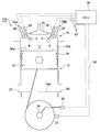
- FIG. 1 is a front cross-sectional view of one embodiment of a dual fuel diesel engine of the present invention. It is a cross-sectional view of the dual fuel diesel engine according to the embodiment.
- (A) is a diagram which shows the fuel injection mode of the dual fuel diesel engine which concerns on the said embodiment
- (B) is a diagram which shows the fuel injection mode of the conventional dual fuel diesel engine.
- (A) And (B) is explanatory drawing which shows the fuel-injection system of the dual fuel diesel engine which concerns on the said embodiment.
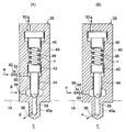
- the structure of a part of the dual fuel diesel engine according to the embodiment is shown, (A) is a front sectional view of the gas fuel injector, and (B) is a front sectional view of the oil fuel injector. It is a mimetic diagram of one embodiment concerning the dual fuel diesel engine unit of the present invention.
- a dual fuel diesel engine 10 ⁇ / b> A of this embodiment includes a cylindrical cylinder 12, a cylinder head 14 coupled to the upper end of the cylinder 12, and a piston 16 accommodated in the cylinder 12 so as to reciprocate. And.
- a combustion chamber c is formed by the peripheral wall 12 a of the cylinder 12, the cylinder head 14, and the top surface 16 a of the piston 16.
- a piston ring 18 is provided on the outer peripheral surface of the piston 16, and seals between the piston outer peripheral surface and the cylinder peripheral wall 12a.
- a plurality of scavenging ports 20 are opened at equal intervals in the circumferential direction on the peripheral wall 12a in the cylinder lower region.
- the scavenging port 20 is formed at a position above the top surface 16a (indicated by a two-dot chain line in the figure) of the piston 16 in the bottom dead center region.
- the scavenging port 20 Air is supplied from 20 to the combustion chamber c.
- an exhaust port is opened at the center of the cylinder head 14, and an exhaust valve 22 for opening and closing the exhaust port is provided at the exhaust port.
- the exhaust valve 22 is opened until the piston 16 reaches a position of about 100 ° before top dead center during the scavenging stroke when the piston 16 is in the ascending process.
- the exhaust gas from the previous stroke remaining in the combustion chamber c is scavenged by the air supplied from the scavenging port 20 to the combustion chamber c.
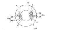
- the cylinder head 14 is provided with two sets of dual fuel injection devices 24 a and 24 b around the exhaust valve 22.
- the dual fuel injectors 24 a and 24 b are arranged at 180 ° intervals from each other at positions symmetrical to the central axis of the cylinder 12.
- the dual fuel injectors 24a and 24b include a gas fuel injector 26 that injects gaseous fuel g such as natural gas into the combustion chamber c, and a pilot fuel injector 28 that also injects oil fuel o with good compression ignitability into the combustion chamber c. It consists of and.
- the gas fuel injector 26 and the pilot fuel injector 28 are connected to an engine control unit (ECU) 30 via a cable 32, and the fuel injection operation is controlled by the ECU 12.
- the ECU 12 is connected via a cable 38 to a crank angle sensor 36 that detects the rotation angle of the crankshaft 34, and a rotation speed sensor 37 that detects the rotation speed of the crankshaft 34.
- the ECU 12 receives the detection signal of the rotation angle of the crankshaft 34 from the crank angle sensor 36 via the cable 38 to detect the phase of the piston 16. Further, the ECU 12 detects the load factor of the dual fuel diesel engine 10 from the detection value of the rotation speed sensor 37 via the cable 38.
- the gas fuel injector 26 and the pilot fuel injector 28 inject gas fuel g and oil fuel o into the combustion chamber c at a predetermined timing according to a signal transmitted from the ECU 12.
- the gas fuel injector 26 and the pilot fuel injector 28 inject the respective fuels almost simultaneously.
- the oil fuel o having good compression ignitability self-ignites, whereby the gas fuel g injected almost simultaneously burns, and a flame is generated in the combustion chamber c.
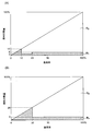
- FIG. 3A shows the fuel injection mode of the dual fuel diesel engine 10A
- FIG. 3B shows the fuel injection mode of the conventional dual fuel diesel engine.
- the horizontal axis represents the load factor of the dual fuel diesel engine 10
- the vertical axis represents the total heat quantity of the injected fuel.
- Rg represents a gas fuel region
- Ro represents an oil fuel region.
- the gas fuel injector 26 and the pilot fuel injector 28 have a minimum limit injection amount for these structural reasons or the nature of the fuel.
- the minimum limit injection amount (heat amount) of one gas fuel injector 26 is 7%
- the minimum limit injection amount (heat amount) of one pilot fuel injector 28 is 3%. It is.
- an extremely low load operation region that is, a region where the load factor is 0 to 10%, only oil fuel is injected from the viewpoint of ignitability.
- the respective fuels are injected from the gas fuel injector 26 and the pilot fuel injector 28 of the dual fuel injector 24a.
- fuel is injected from the gas fuel injector 26 and the pilot fuel injector 28 of the dual fuel injector 24b in the next combustion cycle. This is done alternately for each combustion cycle.
- the injection amount (heat amount) of the oil fuel can be reduced to 3% in the region where the load factor is 10 to 20%.
- FIG. 5A shows a configuration example of the gas fuel injector 26, and FIG. 5B shows a configuration example of the pilot fuel injector 28.
- the gas fuel injector 26 shown in FIG. 5A is provided with a space v in the axial direction inside a cylindrical housing 40, a needle valve 44 integrated with the piston 42, and a spring force increasing mechanism.
- a piston 46 is slidably accommodated.
- a coil spring 48 is interposed between the piston 42 and the spring force increasing piston 46.
- the cylindrical housing 40 includes a flow path 50 communicating with the upper surface side space of the piston 46 for increasing the spring force, a flow path 52 for supplying the hydraulic oil w to the lower surface side space of the piston 42, and a flow for supplying the gas fuel g.
- a passage 54 is formed.
- An injection port 56 is formed in the injection unit 40a disposed in the combustion chamber c.
- a hydraulic oil supply path 60 is connected to the flow path 52, and an electromagnetic opening / closing valve 62 is interposed in the hydraulic oil supply path 60.
- the electromagnetic on-off valve 62 is opened by a command from the ECU 12 and the hydraulic oil w is supplied to the flow path 52, the needle valve 44 rises, and the flow path 52 communicates with the injection port 56 via the flow path 58. Therefore, the gaseous fuel g supplied from the flow path 54 is injected from the injection port 56 into the combustion chamber c. If the hydraulic oil w is not supplied to the flow path 52, the flow path 58 is blocked by the needle valve 44, and the gas fuel g is not injected into the combustion chamber c.
- the spring force of the coil spring 48 with respect to the needle valve 44 can be adjusted by supplying hydraulic oil or working air to the flow path 50.
- the configuration of the pilot fuel injector 28 is the same as that of the gas fuel injector 26 except that there is no flow path 52.
- An oil fuel supply path 64 is connected to the flow path 54, and an electromagnetic opening / closing valve 66 is interposed in the oil fuel supply path 64.
- the electromagnetic on-off valve 66 is opened by a command from the ECU 12 and the oil fuel o is supplied to the flow path 54, the needle valve 44 is raised by the pressure of the oil fuel o, and the flow path 54 and the flow path 58 are communicated. As a result, the oil fuel o is injected from the injection port 56 into the combustion chamber c.
- the injection of the gas fuel g can be controlled by controlling the supply of the hydraulic oil w by the ECU 12 to the gas fuel injector 26.
- the injection of the oil fuel o can be controlled by controlling the supply of the oil fuel o by the ECU 12.
- the ECU 12 automatically shifts to the fuel injection cycle shown in FIGS. 4 (A) and 4 (B).
- the configuration of the gas fuel injector 26 and the pilot fuel injector 28 is not limited to the configuration shown in FIG.
- the minimum limit injection amount of the oil fuel o can be halved in the low load operation region. Therefore, the ratio of the injection amounts of the oil fuel o and the gas fuel g can be maintained within a complete combustible range, and therefore, it is possible to reduce pollution of the exhaust gas and reduce the fuel cost as compared with the conventional case.
- the fuel is alternately injected from the two sets of the dual fuel injection devices 24a and 24b, it is possible to prevent the occurrence of wear, burnout, or the like on one of the dual fuel injection devices.
- the control of the dual fuel injection devices 24a and 24b by the ECU 12 becomes relatively simple, and the cost of the control mechanism can be reduced. Further, the ECU 12 can automate the execution of the fuel injection cycle in the region where the load factor of the dual fuel diesel engine 10 is 10 to 20%.
- the load factor is in the range of 10 to 16%.
- the injection amount (heat amount) of oil fuel can be reduced to 2%. If four or more sets of dual fuel injection devices are provided, the injection amount (heat amount) of the oil fuel can be further reduced.
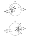
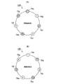
- the dual fuel diesel engine unit 10B of the present embodiment has a plurality (seven in FIG. 6) of cylinders having the same configuration as the cylinder 12 of the dual fuel diesel engine 10A of the above embodiment.
- the seven cylinders 70a to 70g are controlled by the ECU 12 so as to perform the same fuel injection cycle as in the above embodiment. That is, each of the cylinders 70a to 70g includes two sets of binary fuel injectors 24a and 24b, and these binary fuel injectors alternately inject fuel.
- FIG. 6A shows a state when the crankshaft 34 is rotated at an odd number
- FIG. 6B shows a state when the crankshaft 34 is rotated at an even number
- the first group consisting of the cylinders 70a, 70c, 70e, and 70g in the combustion cycle during odd-numbered rotation of the crankshaft 34 by the ECU 12 receives fuel from the dual fuel injectors 24a and 24b. Inject and ignite.
- the second group of fuel injection composed of the cylinders 70b, 70d and 70f is stopped. At the injection timing when the crankshaft 34 rotates evenly, the fuel injection is stopped in the first group and the fuel injection is performed in the second group, contrary to the odd-numbered rotation. Such an operation is performed alternately.
- the oil fuel can be halved in each cylinder as compared with the conventional dual fuel diesel engine having the same structure. Furthermore, since the fuel injection cycle is carried out as a whole dual fuel diesel engine, the oil fuel injection amount can be reduced to a quarter compared to the conventional oil fuel injection amount.
- the cylinders 70a to 70g are divided into two groups, and the fuel injection and the ignition are alternately performed. Instead, the cylinders 70a to 70g are divided into three or more groups, and three or more groups. The fuel injection and the ignition may be performed sequentially. Thereby, the oil fuel injection amount can be further reduced.
- both the first embodiment and the second embodiment are examples in which the present invention is applied to a two-cycle dual fuel diesel engine, the present invention is also applicable to a four-cycle dual fuel diesel engine. .
- the ratio of the oil fuel injection amount to the gas fuel injection amount can be reduced, and it becomes possible to further reduce the pollution of exhaust gas and reduce the fuel cost.
Landscapes
- Engineering & Computer Science (AREA)
- Chemical & Material Sciences (AREA)
- Combustion & Propulsion (AREA)
- Mechanical Engineering (AREA)
- General Engineering & Computer Science (AREA)
- Oil, Petroleum & Natural Gas (AREA)
- Chemical Kinetics & Catalysis (AREA)
- General Chemical & Material Sciences (AREA)
- Output Control And Ontrol Of Special Type Engine (AREA)
- Fuel-Injection Apparatus (AREA)
- Electrical Control Of Air Or Fuel Supplied To Internal-Combustion Engine (AREA)
- Combustion Methods Of Internal-Combustion Engines (AREA)
Abstract
Description
本発明の二元燃料ディーゼルエンジンの一実施形態を図1~図5に基づいて説明する。本実施形態は、2サイクルの二元燃料ディーゼルエンジンに本発明を適用した例である。
次に、本発明の二元燃料ディーゼルエンジンユニットの一実施形態を図6により説明する。本実施形態の二元燃料ディーゼルエンジンユニット10Bは、前記実施形態の二元燃料ディーゼルエンジン10Aのシリンダ12と同一構成のシリンダを複数(図6では7個)有している。7個のシリンダ70a~gは、夫々前記実施形態と同様の燃料噴射サイクルを行うように、ECU12で制御される。即ち、シリンダ70a~gは、夫々2組の二元燃料噴射装置24a及び24bを備え、これらの二元燃料噴射装置は、交互に燃料を噴射する。
Claims (5)
- シリンダヘッドに、パイロット燃料として油燃料を燃焼室に噴射するパイロット燃料噴射装置と、主燃料であるガス燃料を燃焼室に噴射するガス燃料噴射装置とからなる複数組の二元燃料噴射装置を備えた二元燃料ディーゼルエンジンにおいて、
1燃焼サイクルでは前記複数の二元燃料噴射装置の内の一部の二元燃料噴射装置だけが燃料を噴射し、且つ、連続した複数の燃焼サイクルにおいて前記複数の二元燃料噴射装置の全部が少なくとも1回は燃料を噴射する第1の燃料噴射サイクルを、エンジン制御装置による制御によって繰り返し実行可能となるように構成したことを特徴とする二元燃料ディーゼルエンジン。 - 前記シリンダに前記二元燃料噴射装置が2組設けられ、
前記第1の燃料噴射サイクルが、該2組の二元燃料噴射装置から1燃焼サイクル毎に交互に燃料を噴射させるように構成したものであることを特徴とする請求項1に記載の二元燃料ディーゼルエンジン。 - 前記エンジン制御装置に、前記第1の燃料噴射サイクルを行う負荷運転領域を予め設定しておき、該負荷運転領域で該エンジン制御装置によって前記第1の燃料噴射サイクルを行うように構成したことを特徴とする請求項1に記載の二元燃料ディーゼルエンジン。
- 請求項1~3のいずれかの項に記載の二元燃料ディーゼルエンジンが複数のシリンダを有し、各シリンダで前記第1の燃料噴射サイクルを、前記エンジン制御装置による制御によって繰り返し実行可能となるように構成されていると共に、
1燃焼サイクルでは前記複数のシリンダの内の一部だけが前記第1の燃料噴射サイクルを実行し、且つ、連続した複数の燃料サイクルにおいて前記複数のシリンダの全部が少なくとも1回は前記第1の燃料噴射サイクルを実行する第2の燃料噴射サイクルを、前記エンジン制御装置による制御によって繰り返し実行可能となるように構成したことを特徴とする二元燃料ディーゼルエンジン。 - エンジン制御装置に、前記第1の燃料噴射サイクル及び前記第2の燃料噴射サイクルを行う負荷運転領域を予め設定しておき、該負荷運転領域に達したら、該エンジン制御装置によって前記第1の燃料噴射サイクル及び前記第2の燃料噴射サイクルを行うように構成したことを特徴とする請求項4に記載の二元燃料ディーゼルエンジン。
Priority Applications (4)
| Application Number | Priority Date | Filing Date | Title |
|---|---|---|---|
| KR1020147026710A KR101564866B1 (ko) | 2012-04-11 | 2013-02-07 | 이원 연료 디젤 엔진 |
| US14/383,766 US20150300284A1 (en) | 2012-04-11 | 2013-02-07 | Dual-fuel diesel engine |
| CN201380010623.0A CN104126066B (zh) | 2012-04-11 | 2013-02-07 | 双燃料柴油发动机 |
| EP13775868.6A EP2837802A4 (en) | 2012-04-11 | 2013-02-07 | DIESEL ENGINE WITH MIXED FUEL |
Applications Claiming Priority (2)
| Application Number | Priority Date | Filing Date | Title |
|---|---|---|---|
| JP2012-090233 | 2012-04-11 | ||
| JP2012090233A JP5984469B2 (ja) | 2012-04-11 | 2012-04-11 | 二元燃料ディーゼルエンジン |
Publications (1)
| Publication Number | Publication Date |
|---|---|
| WO2013153843A1 true WO2013153843A1 (ja) | 2013-10-17 |
Family
ID=49327423
Family Applications (1)
| Application Number | Title | Priority Date | Filing Date |
|---|---|---|---|
| PCT/JP2013/052935 WO2013153843A1 (ja) | 2012-04-11 | 2013-02-07 | 二元燃料ディーゼルエンジン |
Country Status (6)
| Country | Link |
|---|---|
| US (1) | US20150300284A1 (ja) |
| EP (1) | EP2837802A4 (ja) |
| JP (1) | JP5984469B2 (ja) |
| KR (1) | KR101564866B1 (ja) |
| CN (1) | CN104126066B (ja) |
| WO (1) | WO2013153843A1 (ja) |
Cited By (2)
| Publication number | Priority date | Publication date | Assignee | Title |
|---|---|---|---|---|
| EP3009641A1 (en) * | 2014-10-17 | 2016-04-20 | Man Diesel & Turbo, Filial Af Man Diesel & Turbo Se, Tyskland | A fuel valve for injecting gaseous fuel into a combustion chamber of a self-igniting internal combustion engine and method |
| WO2024088008A1 (zh) * | 2022-10-28 | 2024-05-02 | 中船动力研究院有限公司 | 双燃料协同喷射系统及船舶 |
Families Citing this family (10)
| Publication number | Priority date | Publication date | Assignee | Title |
|---|---|---|---|---|
| WO2015162636A1 (ja) * | 2014-04-22 | 2015-10-29 | 川崎重工業株式会社 | エンジン駆動システムおよび船舶 |
| US10161371B2 (en) | 2015-02-27 | 2018-12-25 | Avl Powertrain Engineering, Inc. | Opposed piston three nozzle piston bowl design |
| US10066590B2 (en) | 2015-02-27 | 2018-09-04 | Avl Powertrain Engineering, Inc. | Opposed piston three nozzle combustion chamber design |
| EP3311016B1 (en) * | 2015-06-17 | 2019-05-01 | Wärtsilä Finland Oy | Method for operating multi-cylinder piston engine and piston engine |
| CN106930849B (zh) * | 2015-12-29 | 2020-10-02 | 长城汽车股份有限公司 | 双燃料发动机燃烧模式的切换控制方法、系统及车辆 |
| US20190085776A1 (en) * | 2017-08-29 | 2019-03-21 | American Gas & Technology | Diesel to natural gas conversion system |
| CN109386396B (zh) * | 2018-09-29 | 2021-09-10 | 哈尔滨工程大学 | 一种天然气发动机燃烧控制方法 |
| JP7132146B2 (ja) * | 2019-02-07 | 2022-09-06 | 株式会社Soken | 燃料噴射システム |
| DE102019209232A1 (de) * | 2019-06-26 | 2020-12-31 | Technische Universität München | HPDF-Betriebsverfahren für eine Brennkraftmaschine, Brennkraftmaschine und Arbeitsvorrichtung |
| DK180809B1 (en) * | 2020-12-09 | 2022-04-07 | Man Energy Solutions Filial Af Man Energy Solutions Se Tyskland | Internal combustion engine |
Citations (6)
| Publication number | Priority date | Publication date | Assignee | Title |
|---|---|---|---|---|
| JPS604761U (ja) * | 1983-06-23 | 1985-01-14 | 三井造船株式会社 | デユアルフユ−エル機関における燃料噴射弁の配置構造 |
| JPS6247742U (ja) * | 1985-09-11 | 1987-03-24 | ||
| JPS6245339B2 (ja) | 1982-05-21 | 1987-09-25 | Kaaru Maiyaa Tekusuteiru Mas Fab Gmbh | |
| JPH09324631A (ja) * | 1996-06-10 | 1997-12-16 | Shin A C Ii:Kk | ディーゼルエンジンの燃料噴射制御方法 |
| JP2003193874A (ja) | 2001-12-26 | 2003-07-09 | Nippon Ekosu Kk | ガス燃料を併用する二元燃料ディーゼルエンジン |
| JP2010190130A (ja) * | 2009-02-19 | 2010-09-02 | Nissan Motor Co Ltd | 圧縮着火内燃機関 |
Family Cites Families (13)
| Publication number | Priority date | Publication date | Assignee | Title |
|---|---|---|---|---|
| JPS6245339U (ja) * | 1985-09-10 | 1987-03-19 | ||
| US4831993A (en) * | 1987-12-28 | 1989-05-23 | Erik Kelgard | Method of operating carburetted dual-fuel engines with diesel pilot oil injection |
| JPH05340295A (ja) * | 1992-06-09 | 1993-12-21 | Toyota Motor Corp | 多気筒内燃機関の制御装置 |
| US5365902A (en) * | 1993-09-10 | 1994-11-22 | General Electric Company | Method and apparatus for introducing fuel into a duel fuel system using the H-combustion process |
| DE19621297C1 (de) * | 1996-05-28 | 1997-12-04 | Man B & W Diesel Ag | Einrichtung zur Steuerung/Regelung der Zündöl-Einspritzung eines Gasmotors |
| AU2001261247A1 (en) * | 2000-05-08 | 2001-11-20 | Cummins, Inc. | Internal combustion engine operable in pcci mode with early control injection and method of operation |
| TW491930B (en) * | 2000-10-10 | 2002-06-21 | Waertsilae Nsd Schweiz Ag | Method for the injection of fuel |
| US7270089B2 (en) * | 2003-06-11 | 2007-09-18 | Clean Air Power, Inc. | Method and apparatus for controlling transition between operating modes in a multimode engine |
| US6866016B2 (en) * | 2003-07-14 | 2005-03-15 | General Electric Company | System and method for controlling ignition in internal combustion engines |
| JP2006046208A (ja) * | 2004-08-05 | 2006-02-16 | Toyota Motor Corp | 筒内噴射型の内燃機関 |
| US7121254B2 (en) * | 2005-02-17 | 2006-10-17 | General Motors Corporation | Compression-ignited IC engine and method of operation |
| US7966992B2 (en) * | 2009-02-15 | 2011-06-28 | Ford Global Technologies, Llc | Combustion control using ion sense feedback and multi-strike spark to manage high dilution and lean AFR |
| US8688351B2 (en) * | 2010-02-26 | 2014-04-01 | Clean Air Power, Inc. | Modification of engine control signal timing by emulation of engine position sensors |
-
2012
- 2012-04-11 JP JP2012090233A patent/JP5984469B2/ja active Active
-
2013
- 2013-02-07 WO PCT/JP2013/052935 patent/WO2013153843A1/ja active Application Filing
- 2013-02-07 US US14/383,766 patent/US20150300284A1/en not_active Abandoned
- 2013-02-07 EP EP13775868.6A patent/EP2837802A4/en not_active Withdrawn
- 2013-02-07 CN CN201380010623.0A patent/CN104126066B/zh active Active
- 2013-02-07 KR KR1020147026710A patent/KR101564866B1/ko active IP Right Grant
Patent Citations (6)
| Publication number | Priority date | Publication date | Assignee | Title |
|---|---|---|---|---|
| JPS6245339B2 (ja) | 1982-05-21 | 1987-09-25 | Kaaru Maiyaa Tekusuteiru Mas Fab Gmbh | |
| JPS604761U (ja) * | 1983-06-23 | 1985-01-14 | 三井造船株式会社 | デユアルフユ−エル機関における燃料噴射弁の配置構造 |
| JPS6247742U (ja) * | 1985-09-11 | 1987-03-24 | ||
| JPH09324631A (ja) * | 1996-06-10 | 1997-12-16 | Shin A C Ii:Kk | ディーゼルエンジンの燃料噴射制御方法 |
| JP2003193874A (ja) | 2001-12-26 | 2003-07-09 | Nippon Ekosu Kk | ガス燃料を併用する二元燃料ディーゼルエンジン |
| JP2010190130A (ja) * | 2009-02-19 | 2010-09-02 | Nissan Motor Co Ltd | 圧縮着火内燃機関 |
Non-Patent Citations (1)
| Title |
|---|
| See also references of EP2837802A4 |
Cited By (3)
| Publication number | Priority date | Publication date | Assignee | Title |
|---|---|---|---|---|
| EP3009641A1 (en) * | 2014-10-17 | 2016-04-20 | Man Diesel & Turbo, Filial Af Man Diesel & Turbo Se, Tyskland | A fuel valve for injecting gaseous fuel into a combustion chamber of a self-igniting internal combustion engine and method |
| US10036334B2 (en) | 2014-10-17 | 2018-07-31 | Man Diesel & Turbo, Filial Af Man Diesel & Turbo Se, Tyskland | Fuel valve for injecting gaseous fuel into a combustion chamber of a self-igniting internal combustion engine and method |
| WO2024088008A1 (zh) * | 2022-10-28 | 2024-05-02 | 中船动力研究院有限公司 | 双燃料协同喷射系统及船舶 |
Also Published As
| Publication number | Publication date |
|---|---|
| JP2013217336A (ja) | 2013-10-24 |
| CN104126066A (zh) | 2014-10-29 |
| EP2837802A1 (en) | 2015-02-18 |
| JP5984469B2 (ja) | 2016-09-06 |
| US20150300284A1 (en) | 2015-10-22 |
| KR20140134685A (ko) | 2014-11-24 |
| KR101564866B1 (ko) | 2015-10-30 |
| CN104126066B (zh) | 2018-05-11 |
| EP2837802A4 (en) | 2016-03-16 |
Similar Documents
| Publication | Publication Date | Title |
|---|---|---|
| JP5984469B2 (ja) | 二元燃料ディーゼルエンジン | |
| JP4100401B2 (ja) | 内燃機関 | |
| AU2013205863B2 (en) | Method for operating an engine | |
| US20150075506A1 (en) | Two-cycle gas engine | |
| JP5851918B2 (ja) | 二元燃料ディーゼルエンジン及びその運転方法 | |
| JP5922830B1 (ja) | ガスエンジン | |
| JP7475109B2 (ja) | 二元燃料大型ディーゼルエンジンの動作方法および二元燃料大型ディーゼルエンジン | |
| JP5765819B2 (ja) | 2サイクルガスエンジン | |
| US20170058817A1 (en) | Control apparatus of engine | |
| JP2022180359A (ja) | 潤滑油制御式点火エンジン燃焼 | |
| JP2006316777A (ja) | 内燃機関 | |
| JP6675887B2 (ja) | クロスヘッド式内燃機関 | |
| JP6930970B2 (ja) | 噴射温度を通じた反応性制御により圧縮点火内燃機関の燃焼を制御する方法 | |
| JP3695011B2 (ja) | 副室式エンジン | |
| JP2006348809A (ja) | 内燃機関 | |
| JP2006257999A (ja) | 内燃機関 | |
| US20170058816A1 (en) | Control apparatus of engine | |
| KR102314994B1 (ko) | 가스-작동형 내연 엔진 및 그 작동 방법 | |
| EP3322886B1 (en) | Method to control the combustion of a compression ignition internal combustion engine with reactivity control through the injection temperature | |
| CN116357449A (zh) | 燃气发动机 | |
| JP2006299851A (ja) | 内燃機関 |
Legal Events
| Date | Code | Title | Description |
|---|---|---|---|
| 121 | Ep: the epo has been informed by wipo that ep was designated in this application |
Ref document number: 13775868 Country of ref document: EP Kind code of ref document: A1 |
|
| REEP | Request for entry into the european phase |
Ref document number: 2013775868 Country of ref document: EP |
|
| WWE | Wipo information: entry into national phase |
Ref document number: 2013775868 Country of ref document: EP |
|
| WWE | Wipo information: entry into national phase |
Ref document number: 14383766 Country of ref document: US |
|
| ENP | Entry into the national phase |
Ref document number: 20147026710 Country of ref document: KR Kind code of ref document: A |
|
| NENP | Non-entry into the national phase |
Ref country code: DE |