WO2013153813A1 - Vacuum heat insulator, and refrigerator-freezer and home wall provided with same - Google Patents
Vacuum heat insulator, and refrigerator-freezer and home wall provided with same Download PDFInfo
- Publication number
- WO2013153813A1 WO2013153813A1 PCT/JP2013/002464 JP2013002464W WO2013153813A1 WO 2013153813 A1 WO2013153813 A1 WO 2013153813A1 JP 2013002464 W JP2013002464 W JP 2013002464W WO 2013153813 A1 WO2013153813 A1 WO 2013153813A1
- Authority
- WO
- WIPO (PCT)
- Prior art keywords
- heat insulating
- glass
- vacuum heat
- core material
- insulating material
- Prior art date
Links
Images


Classifications
-
- F—MECHANICAL ENGINEERING; LIGHTING; HEATING; WEAPONS; BLASTING
- F25—REFRIGERATION OR COOLING; COMBINED HEATING AND REFRIGERATION SYSTEMS; HEAT PUMP SYSTEMS; MANUFACTURE OR STORAGE OF ICE; LIQUEFACTION SOLIDIFICATION OF GASES
- F25D—REFRIGERATORS; COLD ROOMS; ICE-BOXES; COOLING OR FREEZING APPARATUS NOT OTHERWISE PROVIDED FOR
- F25D23/00—General constructional features
- F25D23/06—Walls
-
- F—MECHANICAL ENGINEERING; LIGHTING; HEATING; WEAPONS; BLASTING
- F25—REFRIGERATION OR COOLING; COMBINED HEATING AND REFRIGERATION SYSTEMS; HEAT PUMP SYSTEMS; MANUFACTURE OR STORAGE OF ICE; LIQUEFACTION SOLIDIFICATION OF GASES
- F25D—REFRIGERATORS; COLD ROOMS; ICE-BOXES; COOLING OR FREEZING APPARATUS NOT OTHERWISE PROVIDED FOR
- F25D2201/00—Insulation
- F25D2201/10—Insulation with respect to heat
- F25D2201/12—Insulation with respect to heat using an insulating packing material
- F25D2201/124—Insulation with respect to heat using an insulating packing material of fibrous type
Definitions
- the present invention relates to a vacuum heat insulating material provided with a core material mainly composed of glass fiber, and a refrigerator-freezer and a housing wall using the same, and in particular, suppresses deterioration over time or effectively transfers heat of the core material.
- the present invention relates to a vacuum heat insulating material that can be suppressed to improve heat insulating performance, or both, and a refrigerator-freezer and a housing wall using the vacuum heat insulating material.
- the vacuum heat insulating material generally has a structure in which a core material mainly composed of glass fiber is sealed under reduced pressure inside an outer packaging material having gas barrier properties. Therefore, heat transfer due to a gas component can be suppressed as compared with a case where a similar core material mainly composed of glass fibers is used in a normal pressure state.
- the vacuum heat insulating material having such a configuration can be widely used for electrical appliances such as refrigerators and refrigerators and jar pots, or residential materials such as housing walls, bathtubs and floor heating.
- the glass fiber which is the core material of the vacuum heat insulating material has a hygroscopic property. This is because the glass material itself used for the glass fiber has high affinity for water (hydrophilicity), and its cross-sectional area is as small as several ⁇ m and has a large surface area.
- Patent Document 1 discloses a technique for manufacturing a vacuum heat insulating material using a fiber layer having high durability (water resistance) to water.
- the fiber layer used is mainly glass fiber, and when the dried fiber layer is left in a constant temperature and humidity chamber at 25 ° C. and 50 RH% for 24 hours, the adsorbed moisture content of the fiber layer is 0.3% by weight or less. It has become.
- the heat conduction of the gas component has little influence on the heat transfer, and the heat conduction of the core material which is a solid component is mainly used. . Therefore, in order to improve the heat insulating performance of the vacuum heat insulating material, it is important to suppress the heat conduction of the core material.
- Patent Document 2 discloses a technique for forming a core material using a nonwoven fabric in which inorganic fibers such as glass fibers are arranged in a predetermined direction.
- the core material is configured by laminating a plurality of non-woven fabrics, and the non-woven fabric used is one in which inorganic fibers are extended in a direction substantially parallel to the surface thereof.
- the stiffness of the inorganic fiber is low, the inorganic fiber is bent and entangled between the fibers, and the contact area between the fibers increases, so that the thermal conductivity increases and the heat insulation performance deteriorates. Therefore, Patent Document 2 also discloses that the average fiber diameter of the inorganic fibers is preferably in the range of 3 to 15 ⁇ m, and the average fiber length is preferably in the range of 3 to 15 mm. Has been.
- Patent Document 1 may not be able to suppress aging deterioration of the vacuum heat insulating material.
- the outer packaging material of the vacuum heat insulating material has gas barrier properties, it does not completely block various gases including water vapor. For example, under certain conditions such as high temperature and high humidity, the gas barrier properties may decrease.
- the vacuum heat insulating material it may not be possible to sufficiently suppress the intrusion of water vapor from the outside air. Therefore, if it is a use used for a long period of time, such as a refrigerator-freezer or a housing wall, it is necessary to consider the influence of water vapor entering from the outside air even after being sealed in the outer packaging material. In Patent Document 1, no consideration is given to the influence of such water vapor penetration.
- Patent Document 2 it is difficult to further reduce the heat conduction of the core material of the vacuum heat insulating material.
- Patent Document 2 discloses that the improvement limit of the conventional heat insulation performance can be exceeded by configuring the core material using a nonwoven fabric with improved orientation of inorganic fibers. It has also been suggested that the average fiber diameter and the average fiber length of the inorganic fibers are controlled within a predetermined range to suppress the decrease in the rigidity of the inorganic fibers. However, nothing is disclosed about improving the heat insulating performance from the viewpoints other than the orientation of the inorganic fibers, the fiber diameter, or the fiber length.
- the vacuum heat insulating material encloses the core material mainly composed of glass fiber under reduced pressure, the heat conduction by the core material occupies most of the vacuum heat insulating material. Therefore, even if it is the nonwoven fabric which improved the orientation of the inorganic fiber which optimized the fiber diameter and fiber length as disclosed by patent document 2, as long as the inorganic fiber is a general purpose glass fiber, it is thermal conductivity. It is not possible to expect further reduction. In other words, it can be considered that the use of general-purpose glass fibers itself hinders the reduction of the thermal conductivity of the vacuum heat insulating material.
- the present invention has been made in order to solve such problems, and suppresses aging deterioration of a core material mainly composed of glass fibers even when used for a long period of time, and is mainly composed of glass fibers.
- a vacuum heat insulating material capable of realizing at least one of exhibiting good heat insulating properties by further reducing the heat conduction of the core material, and a refrigerator-freezer and a housing wall including the same.
- a vacuum heat insulating material includes a core material having heat insulation properties, and an outer packaging material that has gas barrier properties and encloses the core material in a sealed state under reduced pressure.
- the core material has [i] at least a CaO content of 5 mol% or less and hydrophobicity, [ii] a ten-point average roughness Rz of the fiber surface is 30 or more, and [ iii] SrO and BaO content is 16 mol% or more, and K 2 O content 7 mol% or more and the content of B 2 O 3 is 4 mol% or more, at least the constituent elements of It is comprised from the glass fiber which satisfy
- the glass fiber has the structural requirement [i]
- the glass fiber has the constituent requirement [ii] or [iii]
- good heat insulation can be exhibited by further reducing the heat conduction of the core material mainly composed of the glass fiber.
- the glass fiber has all of the constituent requirements [i] to [iii]
- this vacuum heat insulating material can be suitably used in fields such as a refrigerator-freezer or a housing wall.
- the present invention includes a vacuum heat insulating material having the above-described configuration, an outer box serving as an outer housing, and an inner box located in the outer box and having an inside serving as a storage space for storing articles. And a refrigerator-freezer having a configuration in which the vacuum heat insulating material is disposed between the outer box and the inner box.
- the present invention includes a residential wall having a vacuum heat insulating material having the above-described configuration and a load-bearing wall, wherein the vacuum heat-insulating material is disposed on the back side of the load-bearing wall.
- the deterioration over time of the core material mainly composed of glass fiber is suppressed even after long-term use, and the heat conduction of the core material mainly composed of glass fiber is further reduced.
- a vacuum heat insulating material capable of realizing at least one of exhibiting good heat insulating properties, a refrigerator-freezer and a housing wall including the same.
- FIG. 1 is a schematic cross-sectional view showing an example of the configuration of the vacuum heat insulating material used in the present invention.
- FIG. 2 is a schematic perspective view showing an example of the configuration of the refrigerator-freezer according to Embodiment 1 of the present invention, including the vacuum heat insulating material shown in FIG.
- FIG. 3 is a schematic cross-sectional view showing an example of a configuration of a residential wall according to Embodiment 2 of the present invention, which includes the vacuum heat insulating material shown in FIG.
- FIG. 4A is a diagram of an observation result of a scanning probe microscope showing a state of a fiber surface of a hydrophobic glass fiber used in a vacuum heat insulating material according to an example of the present invention
- FIG. 4B is related to a comparative example. It is a figure of the observation result of a scanning probe microscope which shows the state of the fiber surface of the conventional glass fiber used for the vacuum heat insulating material.
- the vacuum heat insulating material according to the present invention includes a core material having heat insulating properties, and an outer packaging material having gas barrier properties and enclosing the core material in a vacuum sealed state, and the core material is at least CaO.
- the content is 5 mol% or less, has hydrophobicity, the ten-point average roughness Rz of the fiber surface is 30 or more, the content of SrO and BaO is 16 mol% or more, and K 2 O As long as it is made of glass fiber having a content of 7 mol% or more and a content of B 2 O 3 of 4 mol% or more.
- the vacuum heat insulating material according to the present invention includes a core material having heat insulation properties, and an outer packaging material having gas barrier properties and enclosing the core material in a sealed state under reduced pressure, wherein the core material is at least
- the CaO content may be 5 mol% or less, and the glass fiber may have hydrophobicity.
- the deterioration over time of the core material mainly composed of glass fiber can be suppressed even after long-term use. Therefore, the heat insulating property of the obtained vacuum heat insulating material can be improved.
- the vacuum heat insulating material according to the present invention includes a core material having a heat insulating property, and an outer packaging material having a gas barrier property and enclosing the core material in a sealed state under reduced pressure,
- the fiber surface may have a ten-point average roughness Rz of 30 or more.
- the vacuum heat insulating material which concerns on this invention is equipped with the core material which has heat insulation, and the outer packaging material which has the gas barrier property and encloses the said core material in a pressure-reduced sealing state,
- the said core material is SrO.
- the alkali elution amount based on JIS R3502 may be 300 ⁇ g / g or less as long as the glass fiber has hydrophobicity.
- the glass fiber has an average diameter in the range of 0.1 to 10 ⁇ m, and the core material is oriented in a direction intersecting the glass fiber with respect to the heat transfer direction. You may be comprised so that it may make.
- the glass fiber may include at least one of SrO, BaO, and MgO.
- the content thereof when the glass fiber contains the SrO, the content thereof is in the range of 1 to 12 mol%, and when the glass fiber contains the BaO, the content may be in the range of 5 to 12 mol%.
- the glass material constituting the glass fiber may have a Young's modulus of 71 GPa or more.
- the porosity of the core material may be 90% or more.
- the thermal conductivity of the glass material forming the glass fiber may be 1 W / mK or less.
- the glass fiber may be manufactured using a cathode ray tube glass as a raw material.
- the refrigerator-freezer according to the present invention includes the vacuum heat insulating material having the above-described configuration, an outer box serving as an external housing, an inner box positioned in the outer box, and the inside serving as a storage space for storing articles, And the vacuum heat insulating material is arranged between the outer box and the inner box.
- the vacuum heat insulating material is disposed between the outer box and the inner box, and is disposed at a position that is at least one of the left and right side surfaces and the back surface of the refrigerator-freezer. May be.
- the residential wall according to the present invention is configured to include the vacuum heat insulating material having the structure described above and a load bearing wall, and the vacuum heat insulating material is disposed on the back surface side of the load bearing wall.
- a heat insulating panel material configured by fixing the vacuum heat insulating material to the back surface of the load bearing wall may be used.
- the vacuum heat insulating material 10 which concerns on this Embodiment is comprised from the core material 11 and the outer packaging material 12 (or jacket material).
- the core material 11 is comprised from the glass fiber mentioned later, and has heat insulation.
- the outer packaging material 12 has a gas barrier property and encloses the core material 11 inside in a vacuum-sealed state.
- the core material 11 is obtained by forming glass fibers into a board shape. Specifically, for example, the glass fibers are laminated in a flat plate shape, and the laminate is placed in a jig and pressed. Is heated in a pressurized state and molded to have a density and thickness in a predetermined range.
- the pressurizing condition, heating condition and the like of the glass fiber are not particularly limited, and known conditions can be suitably used in the field of manufacturing the vacuum heat insulating material 10.
- the core material 11 is a structure for exhibiting the heat insulating function in the vacuum heat insulating material 10.
- the apparent thermal conductivity ⁇ app is generally the sum of the gas thermal conductivity ⁇ g, the solid thermal conductivity ⁇ s, the radiation thermal conductivity ⁇ r, and the convection thermal conductivity ⁇ c, It is expressed in
- Solid heat conduction can be reduced by reducing the fiber diameter of the glass fibers constituting the core material 11. That is, if the fiber diameter is reduced, the effect of reducing the heat conduction through the fiber and the effect of reducing the heat conduction through the contact point with the adjacent fiber (that is, the effect of increasing the contact resistance) can be obtained. , Solid heat conduction can be reduced.
- the preferable range of the average fiber diameter of glass fiber is mentioned later.
- the glass fibers substantially contact each other by orienting the glass fibers in a direction intersecting the heat transfer direction.
- the orientation direction of the glass fiber is not particularly limited as long as it is a direction that intersects the heat transfer direction, that is, the thickness direction of the core material 11, but is preferably a (substantially) vertical direction.
- gas heat conduction can be reduced by increasing the porosity of the core material 11.
- the porosity of the core material 11 is preferably 90% or more.
- the bulk density is hermetically sealed in the outer packaging material 12.
- the bulk density is preferably in the range of 210 to 280 kg / m 3 , for example. If it exists in this range, favorable heat insulation performance can be exhibited.
- the bulk density, thickness, and the like of the core material 11 that is not hermetically sealed are not particularly limited, and typical examples include conditions where the density is 200 kg / m 3 and the thickness is 10 mm.
- the core material 11 only needs to be made of glass fibers to be described later, but may contain materials other than glass fibers as necessary.
- materials other than glass fibers include inorganic fibers other than glass fibers such as ceramic fibers, slag wool fibers and rock wool fibers; binder materials such as organic binders, inorganic binders and organic fibers; organic powders and inorganic powders And granule materials such as microcapsule granules. These other materials can be used for the purpose of improving the physical properties (strength, uniformity, rigidity, etc.) of the board-shaped core material 11.
- the outer packaging material 12 is a sheet-like material having gas barrier properties, and specifically includes, for example, a laminate in which a resin film is laminated on both surfaces of a metal thin film such as an aluminum foil or an aluminum vapor deposition layer.
- a resin film is laminated on both surfaces of a metal thin film such as an aluminum foil or an aluminum vapor deposition layer.
- One of the resin films constituting the laminate is a surface protective layer that becomes the outer surface of the vacuum heat insulating material 10, and the other is a heat-welded layer for holding the core material 11 in a vacuum-sealed state inside.
- the type and thickness of the metal thin film, the type and thickness of the resin film, etc. are not particularly limited, and known ones can be suitably used.
- a polyethylene terephthalate (PET) film having a thickness of 12 ⁇ m as a surface protective layer, an aluminum foil (Al foil) having a thickness of 6 ⁇ m as an intermediate layer, and a linear low density having a thickness of 50 ⁇ m as a heat welding layer.
- PET polyethylene terephthalate
- Al foil aluminum foil
- linear low density having a thickness of 50 ⁇ m as a heat welding layer.
- LLDPE polyethylene
- the manufacturing method of the vacuum heat insulating material 10 is not particularly limited, and a known method can be suitably used. Specifically, for example, first, the core material 11 is dried by a drying furnace or the like to remove moisture. Further, the two laminated films are overlapped with the heat-welding layers facing each other, three of the four sides are sealed by heat-welding, and the outer packaging material 12 is formed by forming a bag with one side as an opening. . And after inserting the core material 11 from the said opening part of the outer packaging material 12, and decompressing in decompression equipments, such as a decompression chamber, the said opening part is airtightly sealed by heat welding.
- the drying conditions in the drying furnace, the molding conditions of the outer packaging material 12 (sealing conditions by heat welding, etc.), the decompression conditions in the outer packaging material 12, etc. are not particularly limited, and various conditions known in the field of manufacturing the vacuum heat insulating material 10 are used. It can be used suitably.
- the drying condition can include drying at 140 ° C. for 30 minutes
- the reduced pressure condition can include a condition in which the inside of the outer packaging material 12 is 1 to 200 Pa.
- the vacuum heat insulating material 10 may include members other than the core material 11 and the outer packaging material 12. Specifically, for example, a moisture adsorbent that is hermetically sealed together with the core material 11 inside the outer packaging material 12 can be mentioned.
- the glass fiber used for the core material 11 is preferably a hydrophobic glass fiber, moisture is hardly absorbed. Therefore, even if a slight amount of water vapor enters the outer packaging material 12, it is suppressed from adhering to the fiber surface, and therefore the durability of the core material 11 over time can be improved. Furthermore, since the vacuum heat insulating material 10 includes the moisture adsorbent, even a slight amount of water vapor entering the inside can be adsorbed, and the durability of the core material 11 can be further improved.
- the thermal conductivity of the vacuum heat insulating material 10 according to the present embodiment is not particularly limited, it is preferably 5.4 mW / mK or less, more preferably 3.2 mW / mK or less.
- the thermal conductivity in the present embodiment may be measured by a method based on JIS A1412 (or ASTM518 or ISO8301).
- thermal conductivity of the vacuum heat insulating material 10 according to the present embodiment is relatively very low, there is a case where it is not possible to sufficiently follow the sensitivity of the thermal conductivity according to the above rules. Therefore, in the present embodiment and the examples to be described later, a value directly measured by a thermal conductivity measuring device (auto ⁇ ) HC-074-300 (trade name) manufactured by Eiko Seiki Co., Ltd. is used. Used to evaluate conductivity. Note that HC-074-300 is a measuring device conforming to JIS A1412, ATSM518 and ISO8301.
- the glass fiber used for the core material 11 has (1) a hydrophobic condition that it has hydrophobicity, (2) a surface roughness condition that the state of the fiber surface is relatively rough, and ( 3) What is necessary is just to satisfy
- the glass fiber satisfying the hydrophobic condition (1) that is, the hydrophobic glass fiber has a lower hydrophilicity than a general glass fiber. Since general glass fiber has high hydrophilicity, it easily absorbs moisture (such as water vapor) in the air, and in contact with moisture, alkali components (especially metal elements of Group 1 of the periodic table excluding hydrogen, That is, alkali metal) is easily eluted. In contrast, the hydrophobic glass fiber in the present embodiment has low hydrophilicity and little elution of alkali components.
- the hydrophobicity in the present embodiment can be defined as, for example, the elution amount of the alkali component when it comes into contact with moisture.
- the alkali elution amount may be 300 ⁇ g / g or less in the alkaline component elution test based on JIS R3502-1995.
- the alkali elution amount exceeds 300 ⁇ g / g, it can be considered that the alkali component is eluted to the same extent as general glass fibers, and therefore the stability (water resistance) against water as glass fibers is reduced, and the core When the material 11 is configured, it becomes easy to absorb moisture.
- the 10-point average roughness Rz based on JIS B0601-1976 is preferably 30 or more on the fiber surface of the glass fiber.
- the ten-point average roughness Rz is extracted from the curve representing the roughness (roughness curve) by the reference length L in the direction of the average line, and the peak from the highest peak to the fifth peak from the average line of this extracted part. Is calculated as the sum of the average value of the absolute values of the altitude (Yp) and the average value of the absolute values of the altitudes (Yv) of the bottom valley from the lowest valley bottom to the fifth. Therefore, it can be said that the ten-point average roughness Rz is obtained by quantifying the highest peak in the range of the reference length L of the roughness curve except for an extraordinary height.
- the glass fiber is oriented so as to intersect the heat transfer direction.
- the contact area of the contact points between each other becomes relatively small. That is, compared to the contact area when the fiber surface is smooth, the contact area between the glass fibers is increased because the possibility of contact between the convex portions of the fiber surfaces increases. Get smaller. Therefore, since the thermal resistance of the core material 11 is further increased, the heat insulating performance can be further improved.
- the ten-point average roughness Rz is less than 30 (Rz ⁇ 30)
- the contact area between the glass fibers tends not to be so small that the thermal resistance can be significantly increased.
- the glass fiber in the present embodiment is maintained at the same or higher rigidity as compared with a general-purpose glass fiber.
- the Young's modulus of the glass material constituting the glass fiber is 71 GPa.
- the measurement of Young's modulus is based on JIS R1602.
- the glass fiber using the glass material can exhibit excellent rigidity. Therefore, since the frequency with which the glass fibers constituting the core material 11 are bent or the glass fibers are entangled can be effectively reduced, the contact area between the glass fibers can be reduced.
- the shape retention of the core material 11 composed of the glass fiber is also good, and an increase in the density of the core material 11 can be suppressed or avoided. Therefore, the heat insulation performance of the core material 11 can be further improved.
- the Young's modulus of the glass material is less than 71 GPa, the rigidity of the glass fiber using the glass fiber is lowered. Therefore, there is a possibility that the contact area of the glass fibers constituting the core material 11 increases or the density of the core material 11 increases.
- the specific size of the glass fiber in the present embodiment is not particularly limited, but the average diameter may be in the range of 0.1 to 10 ⁇ m, and preferably in the range of 3 to 5 ⁇ m. If the average fiber diameter is 0.1 ⁇ m or less, the productivity of glass fibers deteriorates, or the probability that the glass fibers are intertwined in a complicated manner and become a fiber array parallel to the heat transfer direction increases, and the amount of heat transfer increases. There is a possibility of doing. On the other hand, if the average fiber diameter is 10 ⁇ m or more, the productivity of the glass fiber is improved, but since the amount of heat transfer through the fiber is increased and the contact resistance is reduced, the solid heat conduction ( ⁇ s) is increased. In addition, (1) hydrophobicity conditions, (2) surface roughness conditions, (3) rigidity conditions, and other properties other than the average diameter are not particularly limited as long as they are within the range of known physical properties. Good.
- the glass fiber in the present embodiment may satisfy at least one of (1) hydrophobicity condition, (2) surface roughness condition, and (3) rigidity condition, but at least two conditions Is preferably satisfied, and more preferably all conditions are satisfied.
- glass fiber hydrophobic glass fiber satisfying two of (1) hydrophobic condition and (2) surface roughness condition
- it is possible to suppress the moisture content by having hydrophobicity There is an advantage that the roughness of the fiber surface is easily maintained.
- the glass fiber is hydrophilic, moisture tends to adhere to the fiber surface, which may corrode the irregularities on the fiber surface and reduce the roughness of the fiber surface.
- the glass fiber is hydrophobic, the adhesion of moisture is suppressed, so that the roughness of the fiber surface is easily maintained.
- it becomes easy to maintain a state where the contact area between the glass fibers is small it is possible to effectively suppress a decrease in thermal conductivity over time.
- glass fiber hydrophobic glass fiber satisfying two of (1) hydrophobic condition and (3) rigidity condition can suppress moisture content by having hydrophobicity, rigidity is reduced.
- the glass fiber is hydrophilic, the core material 11 is likely to contain moisture, whereby an alkali component or the like in the glass fiber is eluted, and the rigidity of the glass fiber may be reduced.
- the glass fiber is hydrophobic, the moisture content of the core material 11 is suppressed, so that good rigidity is easily maintained. As a result, it becomes possible to maintain the shape retainability of the core material 11, so that a decrease in thermal conductivity over time can be effectively suppressed.
- the reduced pressure state (degree of vacuum) inside the vacuum heat insulating material 10 can be made relatively high. If the glass fiber satisfies the (3) rigidity condition, the density of the core material 11 becomes relatively low, so that an appropriate gap is secured between the glass fibers. Furthermore, if the glass fiber satisfies (1) the hydrophobic condition, the core material 11 is difficult to contain moisture. For this reason, even if moisture is contained in the core material 11, the moisture is easily detached due to the hydrophobicity and appropriate gaps. Thereby, even when the core material 11 is dried and when the inside of the outer packaging material 12 is depressurized, moisture is easily detached from the core material 11, and moisture hardly remains inside the outer packaging material 12. As a result, the degree of vacuum inside the vacuum heat insulating material 10 can be relatively increased.
- the glass fiber satisfying the two conditions (2) surface roughness condition and (3) rigidity condition moderate voids are maintained between the glass fibers due to excellent rigidity, and the density of the core material 11 can be reduced.
- the thermal conductivity of the core material 11 can be further reduced.
- the fiber surface is rough, stress concentration is likely to occur in the glass fiber, and therefore the glass fiber tends to be broken or broken.
- the glass fiber has excellent rigidity, breakage or breakage of the glass fiber can be effectively suppressed. Thereby, a moderate space
- the obtained vacuum heat insulating material 10 can further reduce the thermal conductivity, and can also effectively suppress a decrease in the thermal conductivity over time.
- composition of glass material constituting glass fiber may be a composition that satisfies the above-mentioned property conditions (1) to (3). Therefore, the specific composition of the glass material is not particularly limited, but the composition satisfies at least one of the following two composition conditions, preferably both.
- the first composition condition is a condition in which the CaO content is 5 mol% or less.
- the hydrophobic condition can be satisfied among the property conditions described above.
- the glass material when the glass material satisfies the first composition condition, it is preferable that the glass material further contains at least one of SrO, BaO, and MgO.
- the group consisting of oxides of Mg, Ca, Sr and Ba which are elements included in Group 2 elements of the periodic table ( For convenience of explanation, it is referred to as “Group 2 oxide group.”
- CaO and at least one oxide of another element are included, and CaO is preferably 5 mol% or less.
- a composition condition containing at least one of SrO, BaO, and MgO is referred to as a sub-composition condition for convenience of explanation.
- the sub-composition condition may be any condition as long as it contains at least one oxide other than CaO in the group 2 oxide group.
- any one of SrO, BaO, and MgO is used. It may contain only seeds, may contain two kinds (SrO and BaO, or SrO and MgO, or BaO and MgO), or may contain all three kinds.
- the content of these oxides is not particularly limited, but preferably, the content of SrO is in the range of 1 to 12 mol%, the content of BaO is in the range of 1 to 8 mol%, and MgO The content of may be in the range of 5 to 12 mol%.
- the glass fiber obtained is generally Hydrophobic glass fibers that are improved in hydrophobicity compared to typical glass fibers and are less likely to cause moisture to adhere to the fiber surface can be obtained.
- the hydrophobicity of the glass fiber can be improved.
- the content of the group 2 oxide group (including CaO) is within the above range, Further, the hydrophobicity of the glass fiber can be further improved. Therefore, since the hygroscopicity of the core material 11 can be reduced, good heat insulating properties can be exhibited.
- the glass fiber used for the core material 11 can be made hydrophobic, so even if a minute amount of moisture is present inside the outer packaging material 12, the fiber interior It becomes possible to suppress effectively entering. As a result, even if water vapor penetrates slightly from the outside by using the vacuum heat insulating material 10 for a long period of time, it is possible to effectively suppress the deterioration of the glass fiber due to the water vapor, and the heat insulation performance is stable over a long period of time. Can be maintained. Further, since the core material 11 itself has a low hygroscopicity, the core material 11 can be easily dried in the manufacturing process, so that the manufacturing efficiency can be improved or the manufacturing cost can be reduced.
- the glass fiber in the present embodiment has an alkali component, that is, a Group 1 metal element (more specifically, its oxide) because the content of the Group 2 oxide group in the glass material falls within the above range.
- the content of is relatively reduced. Therefore, in addition to the reduction of the alkali elution amount due to the hydrophobicity, the alkali component can be reduced in the first place, so that the alkali elution amount can be further reduced. As a result, the deterioration of the glass fiber can be further suppressed, and the deterioration of the heat insulating performance can be suppressed even when the vacuum heat insulating material 10 is used for a long time.
- the glass fiber in the present embodiment if the glass material that satisfies the sub-composition satisfies all of MgO, SrO, and BaO as the group 2 oxide group, (2) surface roughness condition is realized. It becomes possible to do. That is, by including all group 2 oxide groups, it is possible to achieve an appropriate fiber surface roughness as shown in the examples described later.
- the glass material satisfies the sub-composition condition if the group 2 oxide group contains SrO and BaO, the content of these SrO and BaO is preferably 10 mol% or more. More preferably, it is at least mol%.
- the second composition condition is that the content of SrO and BaO is 16 mol% or more, the content of K 2 O is 7 mol% or more, and the content of B 2 O 3 is 4 mol% or more. It is a condition that there is.
- This second composition condition includes sub-condition 1 in which the SrO and BaO contents are 16 mol% or more, sub-condition 2 in which the K 2 O content is 7 mol% or more, and a B 2 O 3 content of 4 It consists of sub-condition 3 of mol% or more. Therefore, each of these subconditions 1 to 3 will be specifically described.
- sub-condition 1 will be described.
- general-purpose glass fibers are often used.
- the content of SrO and BaO is 1 mol% or less and is often close to 0 mol%. This is because SrO and BaO are relatively expensive among the oxides used in the glass field, and as a glass material for glass fibers, soda glass cullet that is relatively easily available and inexpensive is generally used. Because.
- the glass material contains a group 2 oxide group such as MgO, SrO or BaO as a modified oxide
- the glass network structure is cut due to the structure of the glass material. Therefore, the thermal vibration transmitted through the network structure can be reduced, and as a result, heat conduction as a glass material can be suppressed.
- Sr or Ba has a large atomic weight among the Group 2 elements (or alkaline earth metals) of the periodic table, so that the glass density ⁇ can be increased. Thereby, the effect which suppresses the heat conduction of a glass raw material becomes large.
- the glass material satisfies the second composition condition and contains CaO and MgO, the glass fiber using the glass material satisfies (2) surface roughness condition.
- the lower condition 2 will be described.
- the glass material is kept soft (low viscosity) by containing a large amount of K 2 O, which is an oxide of K. Therefore, good hydrophobicity of the glass material can be realized by the mixing action of K 2 O and Na 2 O. Therefore, among the above-mentioned property conditions, (1) the hydrophobicity condition can be satisfied.
- the mixing ratio of K 2 O and Na 2 O is within this range, the content of K 2 O is relatively increased as compared with general soda glass cullet.
- (1) can be hydrophobic conditions also favorably implemented.
- the mixing ratio of Na 2 O / K 2 O is preferably within the above range.
- the meshwork can be made dense. Therefore, the Young's modulus can be improved without increasing the heat conduction. As a result, (3) the rigidity condition can be satisfied among the property conditions described above.
- B 2 O 3 not only makes the network structure of the glass material dense, but also contributes to the suppression of thermal vibration that transmits the network structure. Specifically, since the atomic weight of B is relatively small compared to Si or O, in the Si—O—B bond in the network structure, the OB bond blocks thermal vibration of the Si—O bond. Or exerts a mitigating action. Thereby, the thermal vibration which transmits a network structure is suppressed.
- the glass material only needs to satisfy the first composition condition or the second composition condition described above.
- all of the first composition condition, sub-composition condition, and second composition condition are satisfied.
- the preferable range of the content of the group 2 oxide group is partly different from the range when only the sub-composition conditions are satisfied.
- the SrO content is in the range of 1 to 12 mol%
- the BaO content is in the range of 1 to 8 mol%.
- the MgO content is preferably in the range of 5 to 12 mol%.
- the SrO content is the same in the range of 1 to 12 mol%, but the BaO content is the same. Is preferably in the range of 1 to 10 mol%, and the MgO content is preferably in the range of 0.1 to 12 mol%.
- the total content of SrO and BaO should be 10 mol% or more. What is necessary is just 16 mol% or more.
- the first composition condition and the second composition condition are independent composition conditions, but by satisfying both of these composition conditions, the composition of the glass material can be further optimized. In particular, if the first composition condition is satisfied by a combination of the sub-composition conditions and the second composition condition is satisfied, any of the above-described property conditions (1) to (3) can be realized. It becomes.
- the thermal conductivity of the glass material in this Embodiment should just be 1 W / mK or less.
- the thermal conductivity of the glass material is measured based on JIS R1611. Specifically, when the specific heat of the glass material is Cp, the thermal diffusion coefficient of the glass material is ⁇ , and the density of the glass material is ⁇ , the thermal conductivity ⁇ of the glass material is calculated based on the following equation 2. .
- the manufacturing method of the glass fiber in this Embodiment is not specifically limited, If a raw material is adjusted so that content of the said 2 group oxide group may enter in the said range, it can use suitably various well-known methods. it can. As a particularly preferred example, there is a method of producing glass fibers by a known fiberizing technique using CRT glass as a raw material.
- CRT glass contains K, MgO, BaO and SrO, and the content of CaO is relatively low. Then, the glass tube cullet which grind
- a raw material composition is prepared using a cathode ray tube glass cullet, and then the raw material composition is melted to obtain a centrifugal fiberizing apparatus.
- a method of producing glass fibers by causing the glass melted by the outflow from a large number of holes.
- the fiber surface state of the produced glass fiber is such that the ten-point average roughness Rz is 30 or more as in the above-mentioned (2) surface roughness condition. It becomes rough.
- the cathode ray tube glass cullet contains MgO, BaO and SrO (sub-composition condition of the first composition condition or sub-condition 1 of the second composition condition), and as a raw material, production of ordinary glass fiber It is estimated that moderate roughness of the fiber surface can be realized because substances with different characteristics are mixed with each other and the mixing state of the raw material composition is moderately dispersed (not well mixed). .
- the raw material compositions may be comprised with cathode ray tube glass cullet, you may mix
- blend glass cullet plate glass cullet, bottle glass cullet, etc.
- B 2 O 3 may be added or the mixing ratio of K 2 O and Na 2 O may be adjusted so as to satisfy the lower conditions 1 to 3.
- glass raw materials may be blended as necessary.
- other glass raw materials include feldspar, dolomite, soda ash, borax, and the like.
- it does not specifically limit about conditions, such as a particle size of glass cullet.
- the refrigerator-freezer 20 includes an outer box 21, an inner box 22, a cooling unit (not shown), and the like.
- the outer box 21 is an external housing of the refrigerator-freezer 20, and is a steel plate box made of, for example, a steel plate or a stainless steel plate.
- the inner box 22 is a resin box that is located in the outer box 21 and is obtained by vacuum molding, for example, ABS resin.
- the inside of the inner box 22 is a storage space for storing items such as food.
- the specific configuration of the storage space is not particularly limited, and is divided into a plurality of storage chambers as appropriate according to the type, application, size, and the like of the refrigerator-freezer 20, and the internal temperature is set.
- the cooling unit (not shown) includes a compressor, a condenser, an evaporator, and a pipe connecting them, and cools each storage chamber in the inner box 22.
- the vacuum heat insulating material 10 is disposed in a space formed between the outer box 21 and the inner box 22 (referred to as “heat insulating space” for convenience of explanation).
- the vacuum heat insulating material 10 may be disposed in any of the heat insulating spaces, but in the present embodiment, it is particularly preferable to be disposed on the left and right side surfaces 20b and the back surface 20c.
- the vacuum heat insulating material 10 is not illustrated between the outer box 21 and the inner box 22, but is illustrated outside the outer box 21. However, in actuality, it is arranged in a heat insulating space between the outer box 21 and the inner box 22.
- the vacuum heat insulating material 10 can be disposed in any of the heat insulating spaces on these surfaces.
- the heat insulation space is also reduced.
- the front surface 20a has the same size as the back surface 20c, but a plurality of doors or drawers are provided corresponding to the plurality of storage chambers of the inner box 22, so that a heat insulating space is formed on the entire surface like the back surface 20c or the side surface 20b. Is not formed. Therefore, it is preferable to dispose the vacuum heat insulating material 10 in any one of the both side surfaces 20b and the back surface 20c where a larger heat insulating space is formed, preferably in the heat insulating space of all surfaces.
- the vacuum heat insulating material 10 is molded in advance as a board body as shown in FIG. 1, and its heat insulating performance is superior to that of the foam type. ing.
- the vacuum heat insulating material 10 can exhibit excellent heat insulating performance even when compared with the conventional vacuum heat insulating material. Therefore, if the vacuum heat insulating material 10 matched to the size of the both side surfaces 20b and the back surface 20c is manufactured and disposed in the heat insulating space of each surface, the majority of the refrigerator-freezer 20 can be well insulated. The refrigeration and freezing function of the freezer 20 can be improved and energy saving can be achieved.
- the vacuum heat insulating material 10 can suppress aged deterioration of heat insulation performance, even if the refrigerator-freezer 20 is used for a long period of time, deterioration of the refrigeration and freezing function and energy saving performance can also be suppressed.
- the heat insulating space on the top surface 20d and the door or drawer on the front surface 20a may be filled with foam type heat insulating material, but the vacuum heat insulating material 10 is also disposed on these surfaces. It goes without saying that it may be done. Moreover, the vacuum heat insulating material 10 should just be fixed to at least one of the outer box 21 and the inner box 22 by the well-known method in the heat insulation space.
- the residential wall 30 includes a load-bearing wall 31, a frame body 32, and a vacuum heat insulating material 10.
- the load-bearing wall 31 is a wall that has a strength capable of resisting forces from the vertical direction and the horizontal direction when it is provided as a building wall and can support the building.
- the specific configuration is not particularly limited, and a known configuration can be suitably used.
- the bearing wall 31 may be a panel formed of a pillar material, a bracing material, a plywood material, or the like.
- the surface 31 a of the load bearing wall 31 is a wall surface of the building, but the vacuum heat insulating material 10 is fixed to the back surface 31 b of the load bearing wall 31. Therefore, the housing wall 30 according to the present embodiment is a heat insulating panel material in which the load-bearing wall 31 and the vacuum heat insulating material 10 are integrated.
- the frame body 32 supports the vacuum heat insulating material 10 by fixing it to the back surface 31 b of the load bearing wall 31, and may have a function of reinforcing the load bearing strength of the load bearing wall 31.
- the frame body 32 is fixed to the load bearing wall 31 by a nail member 33 inserted from the surface 31 a of the load bearing wall 31.
- the vacuum heat insulating material 10 is disposed in the frame 32, and a gap between the frame 32 and the vacuum heat insulating material 10 is filled with the caulking material 36.
- air-tight materials 34 and 35 are provided on the portion of the back surface 31 b of the load bearing wall 31 that is exposed to the outside of the frame body 32 and the outer peripheral surface of the frame body 32.
- the airtight members 34 and 35 function to keep the space between the column or beam and the housing wall 30 airtight when the panelized housing wall 30 is fixed to a column or beam of a building.
- Specific configurations of the airtight materials 34 and 35 and the caulking material 36 are not particularly limited, and known materials can be suitably used.
- the housing wall 30 according to the present embodiment is fixed in a state where the vacuum heat insulating material 10 described in the first embodiment overlaps most of the load bearing wall 31, and the vacuum heat insulating material 10 has a core. Since the heat conduction of the material 11 is further reduced, excellent heat insulating performance can be exhibited even when compared with the conventional vacuum heat insulating material. Therefore, the entire wall can be further effectively insulated. Moreover, since the vacuum heat insulating material 10 can suppress aged deterioration of the heat insulating performance, the heat insulating property is not easily lowered even when used for a long time as a wall of a house. Therefore, it can be suitably used as a wall of a next-generation energy-saving house.
- the housing wall 30 according to the present embodiment may have a configuration in which the vacuum heat insulating material 10 and the load bearing wall 31 are provided, and the vacuum heat insulating material 10 is disposed on the back surface 31b side of the load bearing wall 31.
- the frame body 32 and the like may be omitted.
- the residential wall 30 according to the present embodiment is panelized to be a “heat insulation panel material”, the specific configuration as the heat insulation panel material is not limited to the configuration disclosed in the present embodiment. The structure of a well-known heat insulation panel material is applicable.
- the frame body 32 is fixed to the load bearing wall 31 when the housing wall 30 is made into a panel, but the fixing method of the frame body 32 is not limited to the method using the nail member 33, A method using a fixing member other than the nail member 33 may be used, or a method may be used in which a concave portion, a convex portion, or the like is formed in each of the load bearing wall 31 and the frame body 32 and these are combined and fixed.
- the housing wall 30 according to the present embodiment does not necessarily have to be panelized as a heat insulating panel material, and the vacuum heat insulating material 10 is fixed to the back surface 31b of the load bearing wall 31 when used as a housing wall. It only has to be done. Therefore, when building a house, the house wall 30 according to the present embodiment can be assembled at any time at the building site.
- the field of application of the vacuum heat insulating material 10 according to the present invention is not limited to the refrigerator-freezer according to the second embodiment or the housing wall according to the third embodiment, and various known ones using heat insulating materials. Needless to say, it can be suitably used in the field.
- Alkali elution amount As described above, an elution test for alkali components of glass fibers was performed based on JIS R3502-1995. When the alkali elution amount was 300 ⁇ g / g or less, it was evaluated as “ ⁇ ”, and when it exceeded 300 ⁇ g / g, it was evaluated as “x”.
- thermal conductivity of glass material As described above, the thermal conductivity of the glass material used for the glass fiber was measured based on JIS R1611.
- the thermal conductivity of the vacuum heat insulating material 10 was measured based on JIS A1412 (or ASTM518 or ISO8301) as described above. What is necessary is just to measure by the prescribed method. As described above, in order to effectively follow the sensitivity of thermal conductivity, in the following examples, comparative examples, and reference examples, a thermal conductivity measuring device (auto ⁇ ) HC-manufactured by Hidehiro Seiki Co., Ltd. A value directly measured by 074-300 (trade name) was used for evaluating the thermal conductivity of the vacuum heat insulating material 10.
- Example 1 Hydrophobic glass fibers having an average diameter of 4 ⁇ m were produced by a centrifugal fiberizing apparatus using a cathode ray tube glass cullet as a raw material composition.
- the composition of the obtained hydrophobic glass fiber is shown in Table 1.
- B 2 O 3 and Al 2 O 3 are collectively referred to as “Group 13 oxide” (Group 13 element). The meaning of oxide).
- alkali components, Group 2 oxide groups, and oxides other than Group 13 oxides are collectively described as “other oxides” for convenience.
- the state of the fiber surface was measured at a spacing of 1.73 ⁇ m along the longitudinal direction (longitudinal direction) of the fiber, using a scanning probe microscope (manufactured by Shimadzu Corporation, trade name: SPM-). 9700), as shown in FIG. 4A, the maximum value of the vertical axis, that is, the difference between the lowest concave portion and the highest convex portion of the fiber surface is 57.56 nm, and the difference is 40 within the interval of 1.73 ⁇ m. Many irregularities falling within the range of ⁇ 50 nm were confirmed. Moreover, the average height of the fiber surface shown with a dotted line in the figure was 25 nm.
- Table 1 shows the results of alkali elution amount and 10-point average roughness of the obtained hydrophobic glass fiber.
- the obtained hydrophobic glass fibers were laminated so as to have a predetermined size, and heated and pressed using a metal jig to obtain a core material 11 having a thickness of 10 mm.
- the obtained core material 11 was dried in a drying furnace at 140 ° C. for 30 minutes.
- a bag-like shape is formed by using a laminate film in which a PET film (surface protective layer) having a thickness of 12 ⁇ m, an Al foil (intermediate layer) having a thickness of 6 ⁇ m, and an LLDPE film (thermal welding layer) having a thickness of 50 ⁇ m are laminated.
- the outer packaging material 12 was molded, and the core material 11 was inserted into the outer packaging material 12.
- Comparative Example 1 A comparative vacuum heat insulating material 1 was manufactured in the same manner as in the above example except that the core material 11 was made of general glass fiber. Table 1 shows the composition of the glass fibers constituting the core material 11.
- the maximum value of the vertical axis was 8.48 nm, and a single large convex portion was present in the interval of 1.74 ⁇ m. Except for confirmation, it was almost flat. Moreover, the average height of the fiber surface shown with a dotted line in the figure was 3 nm.
- the vacuum heat insulating material 10 of Example 1 had half the heat conductivity of the comparative vacuum heat insulating material 1 and had excellent heat insulating performance.
- the hydrophobic glass fiber used as the core material 11 has a fiber surface rougher than that of the glass fiber of Comparative Example 1, and the numerical value of the ten-point average roughness Rz is 30 or more. And improved heat insulation performance.
- the hydrophobic glass fiber of the vacuum heat insulating material 10 has a small amount of alkali elution and has a good hydrophobicity (water resistance), so that the heat insulating performance can be stably maintained over a long period of time. It was.
- At least the hydrophobic condition and (2) the surface roughness condition can be satisfied among the above-described property conditions.
- Example 2 A cathode ray tube glass cullet is used as a raw material composition, the alkali component and the group 2 oxide group are adjusted so as to satisfy the second composition condition, and B 2 O 3 is added.
- the core material 11 and the vacuum heat insulating material 10 of Examples 2 to 6 were produced.
- Table 2 shows the composition of the glass fibers constituting the core material 11 of each example.
- Comparative Example 2 A core material 11 and a comparative vacuum heat insulating material 2 of Comparative Example 2 were produced in the same manner as in Example 1 except that general soda glass cullet was used as the raw material composition. In addition, Table 2 shows the composition of the glass fiber constituting the core material 11 of Comparative Example 2.
- the vacuum heat insulating materials 10 of Examples 2 to 6 had an excellent heat insulating performance because their thermal conductivity was less than half that of the comparative vacuum heat insulating material 2.
- the glass materials of the glass fibers used in Examples 2 to 6 and Comparative Example 2 were all 71 GPa or more, but the thermal conductivity of Comparative Example 2 exceeded 1.00 W / mK.
- all of Examples 2 to 6 were less than 1.00 W / mK, and it was revealed that the heat insulating property of the glass fiber itself was excellent.
- the rigidity condition can be satisfied, and excellent heat insulation can be exhibited.
- the total amount of alkali components in Examples 2 to 6 is smaller than the total amount of alkali components in Comparative Example 2, (1) hydrophobic conditions can be realized.
- Reference Examples 1 and 2 Although the cathode ray tube glass cullet is used as the raw material composition, the core material 11 and the reference vacuum heat insulating material of Reference Examples 1 and 2 are produced in the same manner as in Examples 2 to 6 except that B 2 O 3 is not added. did. In addition, Table 3 shows the composition of the glass fibers constituting the core material 11 of each reference example.
- the reference vacuum heat insulating materials of these reference examples have the thermal conductivity equivalent to that of Example 1, and the thermal conductivity of the glass material also shows a value equivalent to or lower than that of Examples 2 to 6. ing. Therefore, it can be seen that good heat insulation can be realized if the first composition condition and the sub-composition condition are satisfied. However, when the second composition condition is not satisfied (in Reference Examples 1 and 2, the lower condition 3 is not satisfied), the Young's modulus of the glass material is less than 71 GPa. It can be seen that the rigidity condition cannot be satisfied.
- the present invention can exhibit excellent heat insulation by reducing the heat conduction of the core material, it can be widely used in various fields for the purpose of heat insulation, and in particular, further energy saving such as a refrigerator-freezer, a housing wall, etc. It can be suitably used in a field that needs to be realized.
Abstract
This vacuum heat insulator (10) is provided with a heat-insulating core material (11) and a sheath material (12) which exhibits gas barrier properties and which encloses the core material in a decompressed and closed state. Glass fibers that constitute the core material (11) have at least one of the following constituent features: [i] containing not more than 5 mol% of CaO and being hydrophobic, [ii] the ten point average roughness (Rz) of the surface of the glass fibers is not lower than 30, or [iii] containing not less than 16 mol% of SrO and BaO, containing not less than 7 mol% of K2O and containing not less than 4 mol% of B2O3.
Description
本発明は、ガラス繊維を主体とする芯材を備える真空断熱材と、これを用いた冷凍冷蔵庫および住宅壁とに関し、特に、経年劣化を抑制すること、または、芯材の伝熱を有効に抑制して断熱性能を向上させること、もしくは、これらの両方が可能となっている真空断熱材と、この真空断熱材を用いた冷凍冷蔵庫および住宅壁とに関する。
The present invention relates to a vacuum heat insulating material provided with a core material mainly composed of glass fiber, and a refrigerator-freezer and a housing wall using the same, and in particular, suppresses deterioration over time or effectively transfers heat of the core material. The present invention relates to a vacuum heat insulating material that can be suppressed to improve heat insulating performance, or both, and a refrigerator-freezer and a housing wall using the vacuum heat insulating material.
真空断熱材は、一般的には、ガラス繊維を主体とする芯材を、ガスバリア性を有する外包材の内部に減圧密閉して封入する構成となっている。そのため、ガラス繊維を主体とする同様の芯材を常圧状態で用いる場合と比較して、気体成分による伝熱を抑制することができる。このような構成の真空断熱材は、冷凍冷蔵庫、ジャーポット等の電化製品あるいは住宅壁、浴槽、床暖房等の住宅用資材等に広く用いることができる。
The vacuum heat insulating material generally has a structure in which a core material mainly composed of glass fiber is sealed under reduced pressure inside an outer packaging material having gas barrier properties. Therefore, heat transfer due to a gas component can be suppressed as compared with a case where a similar core material mainly composed of glass fibers is used in a normal pressure state. The vacuum heat insulating material having such a configuration can be widely used for electrical appliances such as refrigerators and refrigerators and jar pots, or residential materials such as housing walls, bathtubs and floor heating.
ここで、真空断熱材の芯材であるガラス繊維は吸湿性を有することが知られている。これは、ガラス繊維に用いられるガラス材料そのものが水に対する親和性が高い(親水性である)こと、並びに、その断面積が数μm程度と微細であり表面積が大きいこと等の理由による。
Here, it is known that the glass fiber which is the core material of the vacuum heat insulating material has a hygroscopic property. This is because the glass material itself used for the glass fiber has high affinity for water (hydrophilicity), and its cross-sectional area is as small as several μm and has a large surface area.
一般的なガラスは、実用上では水に対して安定であると見なすことができるものの、実際には、水分の存在により劣化が生じる。それゆえ、ガラス繊維が水分を吸収した状態が継続されると、繊維表面に付着した水分が繊維内部に入り込んでガラス繊維の劣化が生じ、その結果、芯材の強度および断熱性能が低下する。そこで、真空断熱材の製造に際しては、密封前に芯材を十分に乾燥させる必要があるが、乾燥による水分の脱離に長時間を要し、製造効率が低下したりコストが増加したりするおそれがある。
Although general glass can be considered to be stable to water in practical use, in reality, deterioration occurs due to the presence of moisture. Therefore, when the state in which the glass fiber absorbs moisture is continued, moisture attached to the fiber surface enters the inside of the fiber, causing the glass fiber to deteriorate, and as a result, the strength and heat insulating performance of the core material are lowered. Therefore, when manufacturing a vacuum heat insulating material, it is necessary to sufficiently dry the core material before sealing, but it takes a long time for moisture to be removed by drying, resulting in a decrease in manufacturing efficiency and an increase in cost. There is a fear.
そこで、例えば特許文献1には、水への耐久性(耐水性)が高い繊維層を用いて真空断熱材を製造する技術が開示されている。用いられる繊維層は、ガラス繊維を主体とし、乾燥状態の繊維層を25℃、50RH%の恒温恒湿槽内に24時間放置した時に、当該繊維層の吸着水分率が0.3重量%以下となっている。
Therefore, for example, Patent Document 1 discloses a technique for manufacturing a vacuum heat insulating material using a fiber layer having high durability (water resistance) to water. The fiber layer used is mainly glass fiber, and when the dried fiber layer is left in a constant temperature and humidity chamber at 25 ° C. and 50 RH% for 24 hours, the adsorbed moisture content of the fiber layer is 0.3% by weight or less. It has become.
また、近年、真空断熱材に対しては、省エネルギー化をより一層推進するため、断熱性能のさらなる向上が求められている。
In recent years, vacuum insulation has been required to further improve heat insulation performance in order to further promote energy saving.
ここで、真空断熱材は外包材の内部が減圧されていることから、その伝熱においては、気体成分の熱伝導等はほとんど影響がなく、固体成分である芯材の熱伝導が主となる。それゆえ、真空断熱材の断熱性能を向上させる上では、芯材の熱伝導を抑制することが重要となる。
Here, since the inside of the outer packaging material is depressurized in the vacuum heat insulating material, the heat conduction of the gas component has little influence on the heat transfer, and the heat conduction of the core material which is a solid component is mainly used. . Therefore, in order to improve the heat insulating performance of the vacuum heat insulating material, it is important to suppress the heat conduction of the core material.
例えば、特許文献2には、ガラス繊維等の無機繊維を所定の方向に配列させた不織布を用いて芯材を構成する技術が開示されている。この技術では、芯材は複数の不織布を積層して構成されており、用いられる不織布は、その表面とほぼ平行な方向に無機繊維を延在させたものが用いられている。また、無機繊維の剛性が低いと、当該無機繊維が湾曲して繊維同士の絡み合いが発生して繊維同士の接触面積が増加するため、熱伝導率が大きくなって断熱性能を劣化させることも開示されており、それゆえ、特許文献2には、無機繊維の平均繊維径は3~15μmの範囲内であることが好ましく、平均繊維長は3~15mmの範囲内であることが好ましいことも開示されている。
For example, Patent Document 2 discloses a technique for forming a core material using a nonwoven fabric in which inorganic fibers such as glass fibers are arranged in a predetermined direction. In this technique, the core material is configured by laminating a plurality of non-woven fabrics, and the non-woven fabric used is one in which inorganic fibers are extended in a direction substantially parallel to the surface thereof. Also disclosed is that if the stiffness of the inorganic fiber is low, the inorganic fiber is bent and entangled between the fibers, and the contact area between the fibers increases, so that the thermal conductivity increases and the heat insulation performance deteriorates. Therefore, Patent Document 2 also discloses that the average fiber diameter of the inorganic fibers is preferably in the range of 3 to 15 μm, and the average fiber length is preferably in the range of 3 to 15 mm. Has been.
しかしながら、特許文献1に開示される技術では、真空断熱材の経年劣化を抑制することができない可能性がある。
However, the technique disclosed in Patent Document 1 may not be able to suppress aging deterioration of the vacuum heat insulating material.
真空断熱材の外包材は、ガスバリア性を有するといっても、水蒸気を含む各種気体を完全に遮断できるわけではなく、例えば高温多湿等の特定の条件下であればガスバリア性が低下することも知られている。それゆえ、真空断熱材の使用条件によっては、外気からの水蒸気の侵入を十分に抑えることができないことがあり得る。したがって、例えば冷凍冷蔵庫あるいは住宅壁等のように長期間使用される用途であれば、外包材に密封された後であっても外気から侵入する水蒸気の影響を考慮する必要がある。特許文献1には、このような水蒸気の侵入に関する影響については何ら検討されていない。
Even if the outer packaging material of the vacuum heat insulating material has gas barrier properties, it does not completely block various gases including water vapor. For example, under certain conditions such as high temperature and high humidity, the gas barrier properties may decrease. Are known. Therefore, depending on the use conditions of the vacuum heat insulating material, it may not be possible to sufficiently suppress the intrusion of water vapor from the outside air. Therefore, if it is a use used for a long period of time, such as a refrigerator-freezer or a housing wall, it is necessary to consider the influence of water vapor entering from the outside air even after being sealed in the outer packaging material. In Patent Document 1, no consideration is given to the influence of such water vapor penetration.
また、特許文献2に開示される技術では、真空断熱材の芯材の熱伝導をさらに一層低減することは困難となっている。
Further, with the technique disclosed in Patent Document 2, it is difficult to further reduce the heat conduction of the core material of the vacuum heat insulating material.
特許文献2には、無機繊維の配向性を高めた不織布を用いて芯材を構成することにより、従来の断熱性能の改善限界を超えることが可能であると開示されている。また、無機繊維の平均繊維径および平均繊維長を所定の範囲とすることにより、無機繊維の剛性低下の抑制を図ることも示唆されている。しかしながら、無機繊維の配向、繊維径の好適化または繊維長の好適化以外の観点から断熱性能の向上を図ることに関しては何ら開示されていない。
Patent Document 2 discloses that the improvement limit of the conventional heat insulation performance can be exceeded by configuring the core material using a nonwoven fabric with improved orientation of inorganic fibers. It has also been suggested that the average fiber diameter and the average fiber length of the inorganic fibers are controlled within a predetermined range to suppress the decrease in the rigidity of the inorganic fibers. However, nothing is disclosed about improving the heat insulating performance from the viewpoints other than the orientation of the inorganic fibers, the fiber diameter, or the fiber length.
真空断熱材は、前記の通り、ガラス繊維を主体とする芯材を減圧密閉して封入しているため、真空断熱材では、芯材による熱伝導が大部分を占めることになる。したがって、特許文献2に開示されるような、繊維径および繊維長を好適化した無機繊維の配向性を高めた不織布であっても、その無機繊維が汎用のガラス繊維である限り、熱伝導率をより一層低減することは期待できない。言い換えれば、汎用のガラス繊維を用いることそのものが、真空断熱材の熱伝導率の低減を妨げていると見なすことができる。
As described above, since the vacuum heat insulating material encloses the core material mainly composed of glass fiber under reduced pressure, the heat conduction by the core material occupies most of the vacuum heat insulating material. Therefore, even if it is the nonwoven fabric which improved the orientation of the inorganic fiber which optimized the fiber diameter and fiber length as disclosed by patent document 2, as long as the inorganic fiber is a general purpose glass fiber, it is thermal conductivity. It is not possible to expect further reduction. In other words, it can be considered that the use of general-purpose glass fibers itself hinders the reduction of the thermal conductivity of the vacuum heat insulating material.
前述したように、近年の省エネルギー化の推進から、冷凍冷蔵庫においては、断熱箱体の断熱性能を高めて冷却に消費するエネルギーをより一層削減することが求められ、また住宅においては、住宅壁の断熱性能を高めて冷暖房に消費するエネルギーをより一層削減することが求められている。それゆえ、芯材の熱伝導をさらに一層低減することは重要な課題となっている。
As described above, in recent years, with the promotion of energy saving, in refrigerators and refrigerators, it is required to further improve the heat insulation performance of the heat insulation box to further reduce the energy consumed for cooling. There is a demand for further reducing the energy consumed for air conditioning by improving the heat insulation performance. Therefore, it is an important issue to further reduce the heat conduction of the core material.
このように、真空断熱材の実用性をさらに一層向上するためには、芯材の経年劣化の抑制、または、芯材の熱伝導率の低減、もしくはその両方を実現可能とすることが非常に重要となっている。
As described above, in order to further improve the practicality of the vacuum heat insulating material, it is very possible to suppress the aging deterioration of the core material and / or reduce the thermal conductivity of the core material. It is important.
本発明はこのような課題を解決するためになされたものであって、長期間の使用によっても、ガラス繊維を主体とする芯材の経年劣化を抑制すること、および、ガラス繊維を主体とする芯材の熱伝導をさらに一層低減することにより良好な断熱性を発揮することの少なくとも一方を実現することを可能とする真空断熱材と、これを備える冷凍冷蔵庫および住宅壁とを提供することを目的とする。
The present invention has been made in order to solve such problems, and suppresses aging deterioration of a core material mainly composed of glass fibers even when used for a long period of time, and is mainly composed of glass fibers. To provide a vacuum heat insulating material capable of realizing at least one of exhibiting good heat insulating properties by further reducing the heat conduction of the core material, and a refrigerator-freezer and a housing wall including the same. Objective.
本発明に係る真空断熱材は、前記の課題を解決するために、断熱性を有する芯材と、ガスバリア性を有し、前記芯材を減圧密閉状態で内部に封入する外包材と、を備え、前記芯材は、[i]少なくとも、CaO含有量が5モル%以下であって、疎水性を有する、[ii]その繊維表面の十点平均粗さRzが30以上である、および、[iii]SrOおよびBaOの含有量が16モル%以上、かつ、K2O の含有量が7モル%以上、かつ、B2O3の含有量が4モル%以上である、という構成要件の少なくともいずれかを満たすガラス繊維から構成されている。
In order to solve the above problems, a vacuum heat insulating material according to the present invention includes a core material having heat insulation properties, and an outer packaging material that has gas barrier properties and encloses the core material in a sealed state under reduced pressure. The core material has [i] at least a CaO content of 5 mol% or less and hydrophobicity, [ii] a ten-point average roughness Rz of the fiber surface is 30 or more, and [ iii] SrO and BaO content is 16 mol% or more, and K 2 O content 7 mol% or more and the content of B 2 O 3 is 4 mol% or more, at least the constituent elements of It is comprised from the glass fiber which satisfy | fills either.
前記構成によれば、ガラス繊維が構成要件[i]を有していれば、長期間の使用によっても、ガラス繊維を主体とする芯材の経年劣化を抑制することができる。また、ガラス繊維が構成要件[ii]または[iii]を有していれば、ガラス繊維を主体とする芯材の熱伝導をさらに一層低減することにより良好な断熱性を発揮することもできる。さらに、ガラス繊維が構成要件[i]~[iii]の全てを有していれば、芯材の経年劣化の抑制も芯材の熱伝導のさらなる低減も実現することができる。それゆえ、得られる真空断熱材の断熱性を向上させることができる。その結果、この真空断熱材は、冷凍冷蔵庫または住宅壁等の分野に好適に用いることができる。
According to the above configuration, if the glass fiber has the structural requirement [i], it is possible to suppress the aging deterioration of the core material mainly composed of the glass fiber even when used for a long time. In addition, if the glass fiber has the constituent requirement [ii] or [iii], good heat insulation can be exhibited by further reducing the heat conduction of the core material mainly composed of the glass fiber. Furthermore, if the glass fiber has all of the constituent requirements [i] to [iii], it is possible to suppress the deterioration of the core material over time and further reduce the heat conduction of the core material. Therefore, the heat insulating property of the obtained vacuum heat insulating material can be improved. As a result, this vacuum heat insulating material can be suitably used in fields such as a refrigerator-freezer or a housing wall.
また、本発明には、前記構成の真空断熱材と、外部筐体となる外箱と、当該外箱内に位置し、その内部が物品を収納する収納空間となっている内箱と、を備え、前記外箱と前記内箱との間に、前記真空断熱材が配されている構成の冷凍冷蔵庫も含まれる。
Further, the present invention includes a vacuum heat insulating material having the above-described configuration, an outer box serving as an outer housing, and an inner box located in the outer box and having an inside serving as a storage space for storing articles. And a refrigerator-freezer having a configuration in which the vacuum heat insulating material is disposed between the outer box and the inner box.
また、本発明には、前記構成の真空断熱材と、耐力壁と、を備え、前記耐力壁の裏面側に前記真空断熱材が配されている構成の住宅壁も含まれる。
Further, the present invention includes a residential wall having a vacuum heat insulating material having the above-described configuration and a load-bearing wall, wherein the vacuum heat-insulating material is disposed on the back side of the load-bearing wall.
本発明の上記目的、他の目的、特徴、及び利点は、添付図面参照の下、以下の好適な実施態様の詳細な説明から明らかにされる。
The above object, other objects, features, and advantages of the present invention will become apparent from the following detailed description of preferred embodiments with reference to the accompanying drawings.
本発明では、以上の構成により、長期間の使用によっても、ガラス繊維を主体とする芯材の経年劣化を抑制すること、および、ガラス繊維を主体とする芯材の熱伝導をさらに一層低減することにより良好な断熱性を発揮することの少なくとも一方を実現することを可能とする真空断熱材と、これを備える冷凍冷蔵庫および住宅壁とを提供することができる、という効果を奏する。
In the present invention, with the above configuration, the deterioration over time of the core material mainly composed of glass fiber is suppressed even after long-term use, and the heat conduction of the core material mainly composed of glass fiber is further reduced. Thus, there is an effect that it is possible to provide a vacuum heat insulating material capable of realizing at least one of exhibiting good heat insulating properties, a refrigerator-freezer and a housing wall including the same.
本発明に係る真空断熱材は、断熱性を有する芯材と、ガスバリア性を有し、前記芯材を減圧密閉状態で内部に封入する外包材と、を備え、前記芯材は、少なくとも、CaO含有量が5モル%以下であって、疎水性を有し、その繊維表面の十点平均粗さRzが30以上であり、SrOおよびBaOの含有量が16モル%以上、かつ、K2O の含有量が7モル%以上、かつ、B2O3の含有量が4モル%以上である、ガラス繊維から構成されていればよい。
The vacuum heat insulating material according to the present invention includes a core material having heat insulating properties, and an outer packaging material having gas barrier properties and enclosing the core material in a vacuum sealed state, and the core material is at least CaO. The content is 5 mol% or less, has hydrophobicity, the ten-point average roughness Rz of the fiber surface is 30 or more, the content of SrO and BaO is 16 mol% or more, and K 2 O As long as it is made of glass fiber having a content of 7 mol% or more and a content of B 2 O 3 of 4 mol% or more.
前記構成によれば、長期間の使用によっても、ガラス繊維を主体とする芯材の経年劣化を抑制することができるとともに、ガラス繊維を主体とする芯材の熱伝導をさらに一層低減することにより良好な断熱性を発揮することもできる。それゆえ、得られる真空断熱材の断熱性を向上させることができる。
According to the above-described configuration, it is possible to suppress the deterioration over time of the core material mainly composed of glass fiber even after long-term use, and further reduce the heat conduction of the core material mainly composed of glass fiber. Good thermal insulation can also be exhibited. Therefore, the heat insulating property of the obtained vacuum heat insulating material can be improved.
あるいは、本発明に係る真空断熱材は、断熱性を有する芯材と、ガスバリア性を有し、前記芯材を減圧密閉状態で内部に封入する外包材と、を備え、前記芯材は、少なくとも、CaO含有量が5モル%以下であって、疎水性を有するガラス繊維から構成されてもよい。
Alternatively, the vacuum heat insulating material according to the present invention includes a core material having heat insulation properties, and an outer packaging material having gas barrier properties and enclosing the core material in a sealed state under reduced pressure, wherein the core material is at least The CaO content may be 5 mol% or less, and the glass fiber may have hydrophobicity.
前記構成によれば、長期間の使用によっても、ガラス繊維を主体とする芯材の経年劣化を抑制することができる。それゆえ、得られる真空断熱材の断熱性を向上させることができる。
According to the above configuration, the deterioration over time of the core material mainly composed of glass fiber can be suppressed even after long-term use. Therefore, the heat insulating property of the obtained vacuum heat insulating material can be improved.
あるいは、本発明に係る真空断熱材は、断熱性を有する芯材と、ガスバリア性を有し、前記芯材を減圧密閉状態で内部に封入する外包材と、を備え、前記芯材は、その繊維表面の十点平均粗さRzが30以上のガラス繊維から構成されてもよい。
Alternatively, the vacuum heat insulating material according to the present invention includes a core material having a heat insulating property, and an outer packaging material having a gas barrier property and enclosing the core material in a sealed state under reduced pressure, The fiber surface may have a ten-point average roughness Rz of 30 or more.
前記構成によれば、ガラス繊維を主体とする芯材の熱伝導をさらに一層低減することにより良好な断熱性を発揮することもできる。それゆえ、得られる真空断熱材の断熱性を向上させることができる。
According to the above configuration, good heat insulation can be exhibited by further reducing the heat conduction of the core material mainly composed of glass fiber. Therefore, the heat insulating property of the obtained vacuum heat insulating material can be improved.
あるいは、本発明に係る真空断熱材は、断熱性を有する芯材と、ガスバリア性を有し、前記芯材を減圧密閉状態で内部に封入する外包材と、を備え、前記芯材は、SrOおよびBaOの含有量が16モル%以上、かつ、K2O の含有量が7モル%以上、かつ、B2O3の含有量が4モル%以上であるガラス繊維から構成されてもよい。
Or the vacuum heat insulating material which concerns on this invention is equipped with the core material which has heat insulation, and the outer packaging material which has the gas barrier property and encloses the said core material in a pressure-reduced sealing state, The said core material is SrO. And a BaO content of 16 mol% or more, a K 2 O content of 7 mol% or more, and a B 2 O 3 content of 4 mol% or more.
前記構成によれば、ガラス繊維を主体とする芯材の熱伝導をさらに一層低減することにより良好な断熱性を発揮することもできる。それゆえ、得られる真空断熱材の断熱性を向上させることができる。
According to the above configuration, good heat insulation can be exhibited by further reducing the heat conduction of the core material mainly composed of glass fiber. Therefore, the heat insulating property of the obtained vacuum heat insulating material can be improved.
前記構成の真空断熱材においては、前記ガラス繊維が疎水性を有していれば、JIS R3502に基づくアルカリ溶出量が300μg/g以下であってもよい。
In the vacuum heat insulating material having the above structure, the alkali elution amount based on JIS R3502 may be 300 μg / g or less as long as the glass fiber has hydrophobicity.
また、前記構成の真空断熱材においては、前記ガラス繊維は、平均径が0.1~10μmの範囲内であり、前記芯材は、前記ガラス繊維を伝熱方向に対して交差する方向に配向させるよう構成されてもよい。
In the vacuum heat insulating material having the above-described configuration, the glass fiber has an average diameter in the range of 0.1 to 10 μm, and the core material is oriented in a direction intersecting the glass fiber with respect to the heat transfer direction. You may be comprised so that it may make.
また、前記構成の真空断熱材においては、前記ガラス繊維は、SrO、BaO、およびMgOの少なくとも何れかを含有する構成であってもよい。
In the vacuum heat insulating material having the above-described configuration, the glass fiber may include at least one of SrO, BaO, and MgO.
また、前記構成の真空断熱材においては、前記ガラス繊維は、前記SrOを含有する場合には、その含有量が1~12モル%の範囲内であり、前記BaOを含有する場合には、その含有量が1~8モル%の範囲内であり、前記MgOを含有する場合には、その含有量が5~12モル%の範囲内である構成であってもよい。
Further, in the vacuum heat insulating material having the above structure, when the glass fiber contains the SrO, the content thereof is in the range of 1 to 12 mol%, and when the glass fiber contains the BaO, When the content is in the range of 1 to 8 mol% and the MgO is contained, the content may be in the range of 5 to 12 mol%.
また、前記構成の真空断熱材においては、前記ガラス繊維を構成するガラス素材のヤング率が71GPa以上であってもよい。
Moreover, in the vacuum heat insulating material having the above-described configuration, the glass material constituting the glass fiber may have a Young's modulus of 71 GPa or more.
また、前記構成の真空断熱材においては、前記芯材の空隙率は90%以上であってもよい。
Further, in the vacuum heat insulating material having the above configuration, the porosity of the core material may be 90% or more.
また、前記構成の真空断熱材においては、前記ガラス繊維を構成するガラス素材の熱伝導率が1W/mK以下であってもよい。
Further, in the vacuum heat insulating material having the above configuration, the thermal conductivity of the glass material forming the glass fiber may be 1 W / mK or less.
また、前記構成の真空断熱材においては、前記ガラス繊維は、その原料にブラウン管ガラスを用いて製造されたものであってもよい。
Further, in the vacuum heat insulating material having the above-described configuration, the glass fiber may be manufactured using a cathode ray tube glass as a raw material.
本発明に係る冷凍冷蔵庫は、前記構成の真空断熱材と、外部筐体となる外箱と、当該外箱内に位置し、その内部が物品を収納する収納空間となっている内箱と、を備え、前記外箱と前記内箱との間に、前記真空断熱材が配されている構成である。
The refrigerator-freezer according to the present invention includes the vacuum heat insulating material having the above-described configuration, an outer box serving as an external housing, an inner box positioned in the outer box, and the inside serving as a storage space for storing articles, And the vacuum heat insulating material is arranged between the outer box and the inner box.
前記構成の冷凍冷蔵庫においては、前記真空断熱材は、前記外箱および前記内箱の間であって、前記冷凍冷蔵庫の左右の側面および背面の少なくともいずれかとなる位置に配されている構成であってもよい。
In the refrigerator-freezer having the above-described configuration, the vacuum heat insulating material is disposed between the outer box and the inner box, and is disposed at a position that is at least one of the left and right side surfaces and the back surface of the refrigerator-freezer. May be.
また、本発明に係る住宅壁は、前記構成の真空断熱材と、耐力壁と、を備え、前記耐力壁の裏面側に前記真空断熱材が配されている構成である。
Further, the residential wall according to the present invention is configured to include the vacuum heat insulating material having the structure described above and a load bearing wall, and the vacuum heat insulating material is disposed on the back surface side of the load bearing wall.
前記構成の住宅壁においては、前記耐力壁の裏面に前記真空断熱材が固定されて構成される断熱パネル材であってもよい。
In the residential wall having the above-described structure, a heat insulating panel material configured by fixing the vacuum heat insulating material to the back surface of the load bearing wall may be used.
以下、本発明の好ましい実施の形態を、図面を参照しながら説明する。なお、以下では全ての図を通じて同一又は相当する要素には同一の参照符号を付して、その重複する説明を省略する。
Hereinafter, preferred embodiments of the present invention will be described with reference to the drawings. In the following description, the same or corresponding elements are denoted by the same reference symbols throughout the drawings, and redundant description thereof is omitted.
(実施の形態1)
[真空断熱材の構成]
まず、本実施の形態に係る真空断熱材の一例について、図1を参照して具体的に説明する。図1に示すように、本実施の形態に係る真空断熱材10は、芯材11および外包材12(あるいは外被材)から構成されている。芯材11は、後述するガラス繊維から構成されており、断熱性を有している。外包材12は、ガスバリア性を有し、芯材11を減圧密閉状態で内部に封入している。 (Embodiment 1)
[Configuration of vacuum insulation]
First, an example of the vacuum heat insulating material according to the present embodiment will be specifically described with reference to FIG. As shown in FIG. 1, the vacuum heat insulating material 10 which concerns on this Embodiment is comprised from the core material 11 and the outer packaging material 12 (or jacket material). The core material 11 is comprised from the glass fiber mentioned later, and has heat insulation. The outer packaging material 12 has a gas barrier property and encloses the core material 11 inside in a vacuum-sealed state.
芯材11は、ガラス繊維がボード状に成形されたものであり、具体的には、例えば、ガラス繊維を平板状に積層し、この積層体を治具内に載置して加圧プレス等により加圧状態で加熱し、所定範囲の密度および厚さとなるように成形することにより得られる。ガラス繊維の加圧条件、加熱条件等は特に限定されず、真空断熱材10の製造分野で公知の条件を好適に用いることができる。
The core material 11 is obtained by forming glass fibers into a board shape. Specifically, for example, the glass fibers are laminated in a flat plate shape, and the laminate is placed in a jig and pressed. Is heated in a pressurized state and molded to have a density and thickness in a predetermined range. The pressurizing condition, heating condition and the like of the glass fiber are not particularly limited, and known conditions can be suitably used in the field of manufacturing the vacuum heat insulating material 10.
芯材11は真空断熱材10における断熱機能を発揮するための構成である。そして、その見かけの熱伝導率λapp は、一般に気体熱伝導率λg 、固体熱伝導率λs 、輻射の熱伝導率λr 、対流の熱伝導率λc との和であって、次の式1のように表される。
The core material 11 is a structure for exhibiting the heat insulating function in the vacuum heat insulating material 10. The apparent thermal conductivity λapp is generally the sum of the gas thermal conductivity λg, the solid thermal conductivity λs, the radiation thermal conductivity λr, and the convection thermal conductivity λc, It is expressed in
λapp =λg +λs +λr +λc ・・・(式1)
ここで、対流による熱伝導は、約20kPa以下の減圧条件下もしくは空隙径1mm程度から影響が無視できるようになり(λc ≒0)、また、輻射による熱伝導は、100℃以下の使用温度条件下では影響がない(λr ≒0)。そのため、真空断熱材10の熱伝導は、100℃以下の使用温度条件下では、固体熱伝導(λs )と気体熱伝導(λg )とが支配的となる。 λapp = λg + λs + λr + λc (Formula 1)
Here, heat conduction by convection can be neglected under reduced pressure of about 20 kPa or less or a gap diameter of about 1 mm (λc ≈ 0), and heat conduction by radiation is under operating temperature conditions of 100 ° C. or less. There is no effect below (λr ≈ 0). For this reason, the heat conduction of the vacuum heat insulating material 10 is dominated by solid heat conduction (λs) and gas heat conduction (λg) under operating temperature conditions of 100 ° C. or less.
固体熱伝導は、芯材11を構成するガラス繊維の繊維径を小さくすることで低減することができる。すなわち、繊維径を小さくすれば、繊維中を通しての熱伝導が低減する効果と、隣接する繊維との接触点を通しての熱伝導を小さくする効果(つまり接触抵抗が大きくなる効果)とが得られるため、固体熱伝導を低減することができる。なお、ガラス繊維の平均繊維径の好ましい範囲については後述する。
Solid heat conduction can be reduced by reducing the fiber diameter of the glass fibers constituting the core material 11. That is, if the fiber diameter is reduced, the effect of reducing the heat conduction through the fiber and the effect of reducing the heat conduction through the contact point with the adjacent fiber (that is, the effect of increasing the contact resistance) can be obtained. , Solid heat conduction can be reduced. In addition, the preferable range of the average fiber diameter of glass fiber is mentioned later.
加えて、ガラス繊維を伝熱方向に対して交差する方向に配向させることで、ガラス繊維同士を実質的に点接触させることが可能となる。これにより芯材11の熱抵抗が増大し、固体熱伝導をさらに低減することができる。ガラス繊維の配向方向は、伝熱方向すなわち芯材11の厚さ方向に対して交差する方向であれば、その角度は特に限定されないが、特に好ましくは(略)垂直方向である。ガラス繊維を垂直に配向させることで、ガラス繊維同士を点接触させやすくすることができるので、芯材11の熱抵抗を増大させやすくすることができる。
In addition, it is possible to make the glass fibers substantially contact each other by orienting the glass fibers in a direction intersecting the heat transfer direction. Thereby, the thermal resistance of the core material 11 increases, and solid heat conduction can further be reduced. The orientation direction of the glass fiber is not particularly limited as long as it is a direction that intersects the heat transfer direction, that is, the thickness direction of the core material 11, but is preferably a (substantially) vertical direction. By orienting the glass fibers vertically, the glass fibers can be easily brought into point contact with each other, so that the thermal resistance of the core material 11 can be easily increased.
また気体熱伝導は、芯材11の空隙率を大きくすることで低減することができる。本実施の形態では、芯材11の空隙率は90%以上であることが好ましい。これによって、前述したガラス繊維の繊維径の小径化と、ガラス繊維の配向方向の規定との組み合わせにより、断熱性能をより一層向上させることができる。
Moreover, gas heat conduction can be reduced by increasing the porosity of the core material 11. In the present embodiment, the porosity of the core material 11 is preferably 90% or more. Thereby, the heat insulation performance can be further improved by the combination of the reduction of the fiber diameter of the glass fiber and the regulation of the orientation direction of the glass fiber.
ガラス繊維のその他の条件、例えば嵩密度、厚さ等の諸条件は特に限定されず、公知範囲の密度および厚さであればよいが、嵩密度に関しては、外包材12内に密閉封止したときの嵩密度が、例えば、210~280kg/m3 の範囲内であることが好ましい。この範囲内であれば、良好な断熱性能を発揮することができる。なお、密閉封止されない状態の芯材11の嵩密度、厚さ等は特に限定されず、代表的な一例としては、密度が200kg/m3 、厚さが10mmの条件を挙げることができる。
Other conditions of the glass fiber, such as various conditions such as bulk density and thickness, are not particularly limited, and may be any known density and thickness. However, the bulk density is hermetically sealed in the outer packaging material 12. The bulk density is preferably in the range of 210 to 280 kg / m 3 , for example. If it exists in this range, favorable heat insulation performance can be exhibited. The bulk density, thickness, and the like of the core material 11 that is not hermetically sealed are not particularly limited, and typical examples include conditions where the density is 200 kg / m 3 and the thickness is 10 mm.
また、芯材11は、後述するガラス繊維から構成されていればよいが、必要に応じてガラス繊維以外の材料を含んでいてもよい。このような他の材料としては、例えば、セラミック繊維、スラグウール繊維、ロックウール繊維等のガラス繊維以外の無機繊維;有機バインダ、無機バインダ、有機繊維等のバインダ材;有機粉体、無機粉体、マイクロカプセル粒体等の粒体材料;等を挙げることができる。これらその他の材料は、ボード状の芯材11の物性(強度、均一性、剛性等)を向上させる等の目的で用いることができる。
Further, the core material 11 only needs to be made of glass fibers to be described later, but may contain materials other than glass fibers as necessary. Examples of such other materials include inorganic fibers other than glass fibers such as ceramic fibers, slag wool fibers and rock wool fibers; binder materials such as organic binders, inorganic binders and organic fibers; organic powders and inorganic powders And granule materials such as microcapsule granules. These other materials can be used for the purpose of improving the physical properties (strength, uniformity, rigidity, etc.) of the board-shaped core material 11.
外包材12は、ガスバリア性を有するシート状のものであり、具体的には、例えば、アルミニウム箔またはアルミニウム蒸着層等の金属薄膜の両面に樹脂フィルムが積層された積層体を挙げることができる。積層体を構成する樹脂フィルムのうち一方は、真空断熱材10の外表面となる表面保護層となり、他方は、内部に芯材11を減圧密閉状態で保持するための熱溶着層となっている。金属薄膜の種類および厚さ、樹脂フィルムの種類および厚さ等は特に限定されず、公知のものを好適に用いることができる。より具体的な一例としては、表面保護層として厚さ12μmのポリエチレンテレフタレート(PET)フィルム、中間層として厚さ6μmのアルミニウム箔(Al箔)、熱溶着層として厚さ50μmの直鎖状低密度ポリエチレン(LLDPE)フィルムからなるラミネートフィルムを挙げることができる。
The outer packaging material 12 is a sheet-like material having gas barrier properties, and specifically includes, for example, a laminate in which a resin film is laminated on both surfaces of a metal thin film such as an aluminum foil or an aluminum vapor deposition layer. One of the resin films constituting the laminate is a surface protective layer that becomes the outer surface of the vacuum heat insulating material 10, and the other is a heat-welded layer for holding the core material 11 in a vacuum-sealed state inside. . The type and thickness of the metal thin film, the type and thickness of the resin film, etc. are not particularly limited, and known ones can be suitably used. As a more specific example, a polyethylene terephthalate (PET) film having a thickness of 12 μm as a surface protective layer, an aluminum foil (Al foil) having a thickness of 6 μm as an intermediate layer, and a linear low density having a thickness of 50 μm as a heat welding layer. A laminate film made of a polyethylene (LLDPE) film can be exemplified.
真空断熱材10の製造方法も特に限定されず、公知の方法を好適に用いることができる。具体的には、例えば、まず、芯材11を乾燥炉等により乾燥して水分を除去する。また、2枚のラミネートフィルムを、互いの熱溶着層同士を対向させて重ね合わせ、四辺のうち三方を熱溶着によりシールし、一辺を開口部として袋状にすることで外包材12を成形する。そして、外包材12の前記開口部から芯材11を挿入し、減圧チャンバ等の減圧設備内で減圧してから、前記開口部を熱溶着により密閉封止する。
The manufacturing method of the vacuum heat insulating material 10 is not particularly limited, and a known method can be suitably used. Specifically, for example, first, the core material 11 is dried by a drying furnace or the like to remove moisture. Further, the two laminated films are overlapped with the heat-welding layers facing each other, three of the four sides are sealed by heat-welding, and the outer packaging material 12 is formed by forming a bag with one side as an opening. . And after inserting the core material 11 from the said opening part of the outer packaging material 12, and decompressing in decompression equipments, such as a decompression chamber, the said opening part is airtightly sealed by heat welding.
なお、乾燥炉による乾燥条件、外包材12の成形条件(熱溶着によるシール条件等)、外包材12内の減圧条件等は特に限定されず、真空断熱材10の製造分野で公知の諸条件を好適に用いることができる。例えば、乾燥条件としては、140℃で30分間の乾燥を挙げることができ、減圧条件としては、外包材12の内部が1~200Paとなる条件を挙げることができる。
The drying conditions in the drying furnace, the molding conditions of the outer packaging material 12 (sealing conditions by heat welding, etc.), the decompression conditions in the outer packaging material 12, etc. are not particularly limited, and various conditions known in the field of manufacturing the vacuum heat insulating material 10 are used. It can be used suitably. For example, the drying condition can include drying at 140 ° C. for 30 minutes, and the reduced pressure condition can include a condition in which the inside of the outer packaging material 12 is 1 to 200 Pa.
また、真空断熱材10は、芯材11および外包材12以外の部材等を備えていてもよい。具体的には、例えば、外包材12の内部に芯材11とともに密閉封止される水分吸着剤を挙げることができる。
Further, the vacuum heat insulating material 10 may include members other than the core material 11 and the outer packaging material 12. Specifically, for example, a moisture adsorbent that is hermetically sealed together with the core material 11 inside the outer packaging material 12 can be mentioned.
外包材12がガスバリア性を有するといっても、水蒸気を完全に遮断できるわけではないので、わずかならが外包材12を介して水蒸気が内部に入り込む可能性がある。ここで、本実施の形態では、後述するように、芯材11に用いられるガラス繊維が、好ましくは疎水性ガラス繊維であるので、水分が吸収され難い。そのため、わずかな水蒸気が外包材12の内部に入り込んだとしても繊維表面に付着することが抑制され、それゆえ、芯材11の経時的な耐久性を良好なものとできる。さらに、真空断熱材10が水分吸着剤を備えることで、内部に入り込んだわずかな水蒸気も吸着することができ、芯材11の耐久性をさらに向上させることができる。
Even if the outer packaging material 12 has a gas barrier property, it is not possible to completely block the water vapor, so there is a possibility that the water vapor may enter the inside through the outer packaging material 12. Here, in the present embodiment, as will be described later, since the glass fiber used for the core material 11 is preferably a hydrophobic glass fiber, moisture is hardly absorbed. Therefore, even if a slight amount of water vapor enters the outer packaging material 12, it is suppressed from adhering to the fiber surface, and therefore the durability of the core material 11 over time can be improved. Furthermore, since the vacuum heat insulating material 10 includes the moisture adsorbent, even a slight amount of water vapor entering the inside can be adsorbed, and the durability of the core material 11 can be further improved.
本実施の形態に係る真空断熱材10の熱伝導率は特に限定されないが、5.4mW/mK以下であることが好ましく、3.2mW/mK以下であることがより好ましい。ここで、本実施の形態における熱伝導率は、JIS A1412(または、ASTM518もしくはISO8301)に基づく方法で測定すればよい。
Although the thermal conductivity of the vacuum heat insulating material 10 according to the present embodiment is not particularly limited, it is preferably 5.4 mW / mK or less, more preferably 3.2 mW / mK or less. Here, the thermal conductivity in the present embodiment may be measured by a method based on JIS A1412 (or ASTM518 or ISO8301).
ただし、本実施の形態に係る真空断熱材10の熱伝導率は相対的に非常に低いため、前記の規定では、熱伝導率の感度を十分に追従できない場合がある。そこで、本実施の形態および後述する実施例では、英弘精機株式会社製の熱伝導率測定装置(オートλ)HC-074-300(商品名)で直接測定した値を、真空断熱材10の熱伝導率の評価に用いる。なお、HC-074-300は、JIS A1412、ATSM518およびISO8301に準拠した測定装置である。
However, since the thermal conductivity of the vacuum heat insulating material 10 according to the present embodiment is relatively very low, there is a case where it is not possible to sufficiently follow the sensitivity of the thermal conductivity according to the above rules. Therefore, in the present embodiment and the examples to be described later, a value directly measured by a thermal conductivity measuring device (auto λ) HC-074-300 (trade name) manufactured by Eiko Seiki Co., Ltd. is used. Used to evaluate conductivity. Note that HC-074-300 is a measuring device conforming to JIS A1412, ATSM518 and ISO8301.
[ガラス繊維の性質]
次に、芯材11を構成するガラス繊維の性質について具体的に説明する。本実施の形態において芯材11に用いられるガラス繊維は、(1)疎水性を有するという疎水性条件、(2)繊維表面の状態が相対的に粗くなっているという表面粗さ条件、および(3)剛性が良好に維持されているという剛性条件の少なくともいずれかの性質条件を満たすものであればよい。 [Properties of glass fiber]
Next, the property of the glass fiber which comprises the core material 11 is demonstrated concretely. In the present embodiment, the glass fiber used for the core material 11 has (1) a hydrophobic condition that it has hydrophobicity, (2) a surface roughness condition that the state of the fiber surface is relatively rough, and ( 3) What is necessary is just to satisfy | fill the property conditions of at least any one of the rigidity conditions that rigidity is maintained favorable.
まず、(1)疎水性条件について説明する。この(1)疎水性条件を満たすガラス繊維、すなわち疎水性ガラス繊維は、一般的なガラス繊維よりも親水性が低いものである。一般的なガラス繊維は親水性が高いため、空気中の水分(水蒸気等)を吸収しやすく、また、水分に接触した状態ではアルカリ成分(特に、水素を除く周期表第1族の金属元素、すなわちアルカリ金属)が溶出しやすい。これに対して本実施の形態における疎水性ガラス繊維は、親水性が低くアルカリ成分の溶出が少ないものとなっている。
First, (1) the hydrophobic condition will be described. The glass fiber satisfying the hydrophobic condition (1), that is, the hydrophobic glass fiber has a lower hydrophilicity than a general glass fiber. Since general glass fiber has high hydrophilicity, it easily absorbs moisture (such as water vapor) in the air, and in contact with moisture, alkali components (especially metal elements of Group 1 of the periodic table excluding hydrogen, That is, alkali metal) is easily eluted. In contrast, the hydrophobic glass fiber in the present embodiment has low hydrophilicity and little elution of alkali components.
本実施の形態における疎水性は、例えば、水分に接触したときのアルカリ成分の溶出量として定義することができる。具体的には、本実施の形態では、JIS R3502-1995に基づくアルカリ成分の溶出試験においてアルカリ溶出量が300μg/g以下であればよい。アルカリ溶出量が300μg/gを超えると、一般的なガラス繊維と同程度にアルカリ成分が溶出するとみなすことができ、それゆえ、ガラス繊維として水に対する安定性(耐水性)が低くなるとともに、芯材11を構成したときに水分を吸収しやすくなる。
The hydrophobicity in the present embodiment can be defined as, for example, the elution amount of the alkali component when it comes into contact with moisture. Specifically, in the present embodiment, the alkali elution amount may be 300 μg / g or less in the alkaline component elution test based on JIS R3502-1995. When the alkali elution amount exceeds 300 μg / g, it can be considered that the alkali component is eluted to the same extent as general glass fibers, and therefore the stability (water resistance) against water as glass fibers is reduced, and the core When the material 11 is configured, it becomes easy to absorb moisture.
次に、(2)表面粗さ条件について説明する。本実施の形態におけるガラス繊維では、汎用のガラス繊維と比較して、その繊維表面に微細な凹凸が存在することにより、円滑面ではなく粗い面となっている。具体的には、ガラス繊維の繊維表面において、JIS B0601-1976(JIS B0601-2001からは削除)に基づく十点平均粗さRzが30以上となっていることが好ましい。
Next, (2) surface roughness conditions will be described. In the glass fiber in this Embodiment, compared with a general purpose glass fiber, since the micro unevenness | corrugation exists in the fiber surface, it is not a smooth surface but a rough surface. Specifically, the 10-point average roughness Rz based on JIS B0601-1976 (deleted from JIS B0601-2001) is preferably 30 or more on the fiber surface of the glass fiber.
十点平均粗さRzは、粗さを表す曲線(粗さ曲線)から、その平均線の方向に基準長さLだけ抜き取り、この抜き取り部分の平均線から、最も高い山頂から5番目までの山頂の標高(Yp)の絶対値の平均値と、最も低い谷底から5番目までの谷底の標高(Yv)の絶対値の平均値との和、として算出される。したがって、十点平均粗さRzは、並外れた高さを除き、粗さ曲線の基準長さLの範囲内において一番高い山を数値化したものということができる。
The ten-point average roughness Rz is extracted from the curve representing the roughness (roughness curve) by the reference length L in the direction of the average line, and the peak from the highest peak to the fifth peak from the average line of this extracted part. Is calculated as the sum of the average value of the absolute values of the altitude (Yp) and the average value of the absolute values of the altitudes (Yv) of the bottom valley from the lowest valley bottom to the fifth. Therefore, it can be said that the ten-point average roughness Rz is obtained by quantifying the highest peak in the range of the reference length L of the roughness curve except for an extraordinary height.
ガラス繊維の繊維表面の状態が、十点平均粗さRz≧30となるように粗くなっていれば、当該ガラス繊維が伝熱方向に対して交差するように配向されている状態で、ガラス繊維同士の接触点の接触面積が相対的に小さくなる。すなわち、繊維表面の状態が滑らかであるときの接触面積と比較して、粗くなっているときには、互いの繊維表面の凸部同士で接触する可能性が高くなるため、ガラス繊維同士の接触面積が小さくなる。それゆえ、芯材11の熱抵抗がさらに増大するため、断熱性能をより一層向上することができる。一方、十点平均粗さRzが30に満たない場合(Rz<30)、ガラス繊維同士の接触面積が、熱抵抗を有意に増大できる程度に小さくならない傾向にある。
If the fiber surface of the glass fiber is rough so that the ten-point average roughness Rz ≧ 30, the glass fiber is oriented so as to intersect the heat transfer direction. The contact area of the contact points between each other becomes relatively small. That is, compared to the contact area when the fiber surface is smooth, the contact area between the glass fibers is increased because the possibility of contact between the convex portions of the fiber surfaces increases. Get smaller. Therefore, since the thermal resistance of the core material 11 is further increased, the heat insulating performance can be further improved. On the other hand, when the ten-point average roughness Rz is less than 30 (Rz <30), the contact area between the glass fibers tends not to be so small that the thermal resistance can be significantly increased.
次に、(3)剛性条件について説明する。本実施の形態におけるガラス繊維は、汎用のガラス繊維と比較して、その剛性が同程度以上に維持されている。具体的には、ガラス繊維を構成するガラス素材のヤング率が71GPaであることが好ましい。なお、ヤング率の測定は、JIS R1602に基づく。
Next, (3) rigidity conditions will be described. The glass fiber in the present embodiment is maintained at the same or higher rigidity as compared with a general-purpose glass fiber. Specifically, it is preferable that the Young's modulus of the glass material constituting the glass fiber is 71 GPa. The measurement of Young's modulus is based on JIS R1602.
ガラス素材のヤング率が71GPa以上であれば、当該ガラス素材を用いたガラス繊維は優れた剛性を発揮することができる。そのため、芯材11を構成するガラス繊維が湾曲したりガラス繊維同士が絡み合ったりする頻度を有効に低減できるので、ガラス繊維同士の接触面積を低減することができる。
If the Young's modulus of the glass material is 71 GPa or more, the glass fiber using the glass material can exhibit excellent rigidity. Therefore, since the frequency with which the glass fibers constituting the core material 11 are bent or the glass fibers are entangled can be effectively reduced, the contact area between the glass fibers can be reduced.
また、ガラス繊維が良好な剛性を有していれば、当該ガラス繊維で構成される芯材11の形状保持性も良好なものとなり、芯材11の密度増加を抑制または回避することができる。それゆえ、芯材11の断熱性能をより一層向上することができる。一方、ガラス素材のヤング率が71GPa未満であれば、当該ガラス繊維を用いたガラス繊維の剛性が低下する。そのため、芯材11を構成するガラス繊維の接触面積が増加したり、芯材11の密度が増加したりするおそれがある。
In addition, if the glass fiber has good rigidity, the shape retention of the core material 11 composed of the glass fiber is also good, and an increase in the density of the core material 11 can be suppressed or avoided. Therefore, the heat insulation performance of the core material 11 can be further improved. On the other hand, if the Young's modulus of the glass material is less than 71 GPa, the rigidity of the glass fiber using the glass fiber is lowered. Therefore, there is a possibility that the contact area of the glass fibers constituting the core material 11 increases or the density of the core material 11 increases.
また、本実施の形態におけるガラス繊維の具体的なサイズは特に限定されないが、その平均径が0.1~10μmの範囲内であればよく、3~5μmの範囲内であれば好ましい。平均繊維径が0.1μm以下であれば、ガラス繊維の生産性が悪化したり、ガラス繊維が複雑に絡み合って伝熱方向に平行な繊維配列になる確率が増加して伝熱量が増加したりする等の可能性がある。一方、平均繊維径が10μm以上であれば、ガラス繊維の生産性は向上するが、繊維中を通しての伝熱量が増大するとともに接触抵抗が低減するため、固体熱伝導(λs )が増大する。なお、(1)疎水性条件、(2)表面粗さ条件、および(3)剛性条件、並びに平均径以外の他の性質については特に限定されず、公知の物性の範囲内に入っていればよい。
In addition, the specific size of the glass fiber in the present embodiment is not particularly limited, but the average diameter may be in the range of 0.1 to 10 μm, and preferably in the range of 3 to 5 μm. If the average fiber diameter is 0.1 μm or less, the productivity of glass fibers deteriorates, or the probability that the glass fibers are intertwined in a complicated manner and become a fiber array parallel to the heat transfer direction increases, and the amount of heat transfer increases. There is a possibility of doing. On the other hand, if the average fiber diameter is 10 μm or more, the productivity of the glass fiber is improved, but since the amount of heat transfer through the fiber is increased and the contact resistance is reduced, the solid heat conduction (λs) is increased. In addition, (1) hydrophobicity conditions, (2) surface roughness conditions, (3) rigidity conditions, and other properties other than the average diameter are not particularly limited as long as they are within the range of known physical properties. Good.
本実施の形態におけるガラス繊維は、前述した通り、(1)疎水性条件、(2)表面粗さ条件、および(3)剛性条件の少なくともいずれかを満たしていればよいが、少なくとも2つの条件を満たしていることが好ましく、すべての条件を満たしていることがより好ましい。
As described above, the glass fiber in the present embodiment may satisfy at least one of (1) hydrophobicity condition, (2) surface roughness condition, and (3) rigidity condition, but at least two conditions Is preferably satisfied, and more preferably all conditions are satisfied.
例えば、(1)疎水性条件および(2)表面粗さ条件の2つを満たしているガラス繊維(疎水性ガラス繊維)では、疎水性を有することで水分の含有を抑制することができるため、繊維表面の粗さが維持されやすくなる、という利点がある。ガラス繊維が親水性であれば繊維表面に水分が付着しやすくなり、これによって繊維表面の凹凸が侵食されて繊維表面の粗さが低下するおそれがある。これに対して、ガラス繊維が疎水性であれば、水分の付着が抑制されるため、繊維表面の粗さが維持されやすくなる。その結果、ガラス繊維同士の接触面積が小さい状態を維持しやすくなるため、経時的な熱伝導性の低下を有効に抑制することができる。
For example, in glass fiber (hydrophobic glass fiber) satisfying two of (1) hydrophobic condition and (2) surface roughness condition, it is possible to suppress the moisture content by having hydrophobicity, There is an advantage that the roughness of the fiber surface is easily maintained. If the glass fiber is hydrophilic, moisture tends to adhere to the fiber surface, which may corrode the irregularities on the fiber surface and reduce the roughness of the fiber surface. On the other hand, if the glass fiber is hydrophobic, the adhesion of moisture is suppressed, so that the roughness of the fiber surface is easily maintained. As a result, since it becomes easy to maintain a state where the contact area between the glass fibers is small, it is possible to effectively suppress a decrease in thermal conductivity over time.
また、(1)疎水性条件および(3)剛性条件の2つを満たしているガラス繊維(疎水性ガラス繊維)では、疎水性を有することで水分の含有を抑制することができるため、剛性が維持されやすくなる、という利点がある。ガラス繊維が親水性であれば芯材11が水分を含有しやすくなり、これによってガラス繊維内のアルカリ成分等が溶出し、ガラス繊維の剛性が低下するおそれがある。これに対して、ガラス繊維が疎水性であれば、芯材11の水分の含有が抑制されるため、良好な剛性が維持されやすくなる。その結果、芯材11の形状保持性を維持することが可能となるため、経時的な熱伝導性の低下を有効に抑制することができる。
In addition, since glass fiber (hydrophobic glass fiber) satisfying two of (1) hydrophobic condition and (3) rigidity condition can suppress moisture content by having hydrophobicity, rigidity is reduced. There is an advantage that it is easy to maintain. If the glass fiber is hydrophilic, the core material 11 is likely to contain moisture, whereby an alkali component or the like in the glass fiber is eluted, and the rigidity of the glass fiber may be reduced. On the other hand, if the glass fiber is hydrophobic, the moisture content of the core material 11 is suppressed, so that good rigidity is easily maintained. As a result, it becomes possible to maintain the shape retainability of the core material 11, so that a decrease in thermal conductivity over time can be effectively suppressed.
しかも、(1)疎水性条件および(3)剛性条件の2つを満たしていれば、真空断熱材10内部の減圧状態(真空度)を相対的に高くすることができる。ガラス繊維が(3)剛性条件を満たしていれば、芯材11の密度は相対的に低くなるので、ガラス繊維の間に適度な空隙が確保される。さらに、このガラス繊維が(1)疎水性条件を満たしていれば、芯材11は水分を含有しにくくなる。そのため、芯材11内に水分が含まれていても、疎水性および適度な空隙によって水分が脱離しやすくなる。これにより、芯材11の乾燥時にも外包材12内を減圧するときにも、芯材11から水分が脱離しやすく、外包材12の内部に水分が残存しにくくなる。その結果、真空断熱材10内部の真空度を相対的に高くすることができる。
Moreover, if the two conditions (1) hydrophobicity condition and (3) rigidity condition are satisfied, the reduced pressure state (degree of vacuum) inside the vacuum heat insulating material 10 can be made relatively high. If the glass fiber satisfies the (3) rigidity condition, the density of the core material 11 becomes relatively low, so that an appropriate gap is secured between the glass fibers. Furthermore, if the glass fiber satisfies (1) the hydrophobic condition, the core material 11 is difficult to contain moisture. For this reason, even if moisture is contained in the core material 11, the moisture is easily detached due to the hydrophobicity and appropriate gaps. Thereby, even when the core material 11 is dried and when the inside of the outer packaging material 12 is depressurized, moisture is easily detached from the core material 11, and moisture hardly remains inside the outer packaging material 12. As a result, the degree of vacuum inside the vacuum heat insulating material 10 can be relatively increased.
また、(2)表面粗さ条件および(3)剛性条件の2つを満たしているガラス繊維では、優れた剛性によりガラス繊維の間に適度な空隙が維持されて芯材11の密度を低くできるとともに、並びに、繊維表面の粗さによりガラス繊維同士の接触面積の小さくできることから、芯材11の熱伝導率をより一層低下させることができる。ここで、繊維表面が粗いとガラス繊維に応力集中が生じやすく、そのため、ガラス繊維が切れたり折れたりしやすい傾向にある。しかしながら、ガラス繊維が優れた剛性を有していれば、ガラス繊維の切れまたは折れを有効に抑制することができる。これにより、ガラス繊維の間に適度な空隙がより一層良好に維持することができる。
In addition, in the glass fiber satisfying the two conditions (2) surface roughness condition and (3) rigidity condition, moderate voids are maintained between the glass fibers due to excellent rigidity, and the density of the core material 11 can be reduced. In addition, since the contact area between the glass fibers can be reduced by the roughness of the fiber surface, the thermal conductivity of the core material 11 can be further reduced. Here, if the fiber surface is rough, stress concentration is likely to occur in the glass fiber, and therefore the glass fiber tends to be broken or broken. However, if the glass fiber has excellent rigidity, breakage or breakage of the glass fiber can be effectively suppressed. Thereby, a moderate space | gap between glass fibers can be maintained much more favorably.
さらに、(1)疎水性条件、(2)表面粗さ条件、および(3)剛性条件のすべての性質条件を満たしていれば、前述した2つの条件を満たすことによる相乗効果がすべて実現される。それゆえ、得られる真空断熱材10は、熱伝導率をより一層低減できるものとなっており、かつ、経時的な熱伝導率の低下も有効に抑制することが可能となる。
Furthermore, if all the property conditions of (1) hydrophobicity condition, (2) surface roughness condition, and (3) rigidity condition are satisfied, all the synergistic effects by satisfying the above two conditions are realized. . Therefore, the obtained vacuum heat insulating material 10 can further reduce the thermal conductivity, and can also effectively suppress a decrease in the thermal conductivity over time.
[ガラス繊維を構成するガラス素材の組成]
本実施の形態におけるガラス繊維を構成するガラス素材は、前述した(1)~(3)の性質条件を満たすような組成であればよい。それゆえ、ガラス素材の具体的な組成は特に限定されないが、次に示す2つの組成条件の少なくともいずれか、好ましくは両方を満たす組成となっている。 [Composition of glass material constituting glass fiber]
The glass material constituting the glass fiber in the present embodiment may be a composition that satisfies the above-mentioned property conditions (1) to (3). Therefore, the specific composition of the glass material is not particularly limited, but the composition satisfies at least one of the following two composition conditions, preferably both.
まず、第一組成条件は、CaO含有量が5モル%以下となる条件である。この第一組成条件を満たすことで、前述した性質条件のうち、少なくとも(1)疎水性条件を満たすことができる。
First, the first composition condition is a condition in which the CaO content is 5 mol% or less. By satisfying the first composition condition, at least (1) the hydrophobic condition can be satisfied among the property conditions described above.
また、ガラス素材が、この第一組成条件を満たしている場合、さらに、SrO、BaO、およびMgOの少なくとも何れかを含有することが好ましい。言い換えれば、本実施の形態におけるガラス素材は、第一組成条件を満たしている場合には、周期表第2族元素に含まれる元素であるMg,Ca,SrおよびBaの酸化物からなる群(説明の便宜上、「2族酸化物群」と称する。)のうち、CaOと少なくとも他の1種の元素の酸化物とを含んでおり、CaOは5モル%以下であることが好ましい。なお、SrO、BaO、およびMgOの少なくとも何れかを含有する組成条件を、説明の便宜上、副組成条件と称する。
Further, when the glass material satisfies the first composition condition, it is preferable that the glass material further contains at least one of SrO, BaO, and MgO. In other words, when the glass material in the present embodiment satisfies the first composition condition, the group consisting of oxides of Mg, Ca, Sr and Ba, which are elements included in Group 2 elements of the periodic table ( For convenience of explanation, it is referred to as “Group 2 oxide group.”), CaO and at least one oxide of another element are included, and CaO is preferably 5 mol% or less. Note that a composition condition containing at least one of SrO, BaO, and MgO is referred to as a sub-composition condition for convenience of explanation.
ここで、副組成条件は、前記2族酸化物群のうちCaO以外の酸化物を少なくとも1種含有している条件であればよいが、具体的には、SrOまたはBaOまたはMgOのいずれか1種のみを含有してもよいし、2種類(SrOおよびBaO、もしくはSrOおよびMgO、もしくはBaOおよびMgO)を含有してもよいし、3種類全てを含有してもよい。また、これら酸化物の含有量は特に限定されないが、好ましくは、SrOの含有量は1~12モル%の範囲内であり、BaOの含有量は1~8モル%の範囲内であり、MgOの含有量は5~12モル%の範囲内であればよい。
Here, the sub-composition condition may be any condition as long as it contains at least one oxide other than CaO in the group 2 oxide group. Specifically, any one of SrO, BaO, and MgO is used. It may contain only seeds, may contain two kinds (SrO and BaO, or SrO and MgO, or BaO and MgO), or may contain all three kinds. The content of these oxides is not particularly limited, but preferably, the content of SrO is in the range of 1 to 12 mol%, the content of BaO is in the range of 1 to 8 mol%, and MgO The content of may be in the range of 5 to 12 mol%.
ガラス素材の組成に含有される前記2族酸化物群のうち、少なくともCaOの含有量が5モル%以下であれば(すなわち第一組成条件を満たしてれば)、得られるガラス繊維は、一般的なガラス繊維と比較して疎水性が向上して繊維表面に水分が付着しにくい疎水性ガラス繊維とすることが可能となる。
Among the group 2 oxide groups contained in the composition of the glass material, if at least the content of CaO is 5 mol% or less (that is, if the first composition condition is satisfied), the glass fiber obtained is generally Hydrophobic glass fibers that are improved in hydrophobicity compared to typical glass fibers and are less likely to cause moisture to adhere to the fiber surface can be obtained.
さらに、ガラス素材の組成に含有される前記2族酸化物群のうち、CaOが5モル%以上であって、かつ、SrO,BaOおよびMgOの少なくとも1種を含んでいれば(すなわち、第一組成条件および副組成条件を満たしていれば)、ガラス繊維の疎水性の向上が可能であり、特に、前記2族酸化物群の含有量が(CaOも含めて)前記の範囲内にあれば、ガラス繊維の疎水性をより一層良好なものとすることができる。それゆえ、芯材11の吸湿性を低下させることができるので、良好な断熱性を発揮することができる。
Further, in the group 2 oxide group contained in the composition of the glass material, if CaO is 5 mol% or more and contains at least one of SrO, BaO and MgO (that is, the first If the composition conditions and sub-composition conditions are satisfied), the hydrophobicity of the glass fiber can be improved. In particular, if the content of the group 2 oxide group (including CaO) is within the above range, Further, the hydrophobicity of the glass fiber can be further improved. Therefore, since the hygroscopicity of the core material 11 can be reduced, good heat insulating properties can be exhibited.
また、ガラス素材が少なくとも第一組成条件を満たしていれば、芯材11に用いられるガラス繊維が疎水性とすることができるので、外包材12の内部に微量な水分が存在しても繊維内部に入り込むことを有効に抑制することが可能になる。その結果、真空断熱材10を長期間使用することで外部からわずかに水蒸気が侵入したとしても、当該水蒸気によるガラス繊維の劣化を有効に抑制することができ、断熱性能を長期に亘って安定的に維持することが可能となる。また、芯材11そのものの吸湿性が低いことから、製造過程において芯材11を乾燥させやすくすることができるので、製造効率の向上あるいは製造コストの低減を図ることも可能となる。
Further, if the glass material satisfies at least the first composition condition, the glass fiber used for the core material 11 can be made hydrophobic, so even if a minute amount of moisture is present inside the outer packaging material 12, the fiber interior It becomes possible to suppress effectively entering. As a result, even if water vapor penetrates slightly from the outside by using the vacuum heat insulating material 10 for a long period of time, it is possible to effectively suppress the deterioration of the glass fiber due to the water vapor, and the heat insulation performance is stable over a long period of time. Can be maintained. Further, since the core material 11 itself has a low hygroscopicity, the core material 11 can be easily dried in the manufacturing process, so that the manufacturing efficiency can be improved or the manufacturing cost can be reduced.
また、本実施の形態におけるガラス繊維は、そのガラス素材中の2族酸化物群の含有量が前記範囲内に入るため、アルカリ成分すなわち第1族金属元素(より具体的にはその酸化物)の含有量が相対的に少なくなる。それゆえ、疎水性を有することによるアルカリ溶出量の低減に加えて、そもそもアルカリ成分を少なくすることができるので、アルカリ溶出量をさらに低減することができる。その結果、ガラス繊維の劣化をより一層抑制することができ、真空断熱材10を長期間使用しても断熱性能の劣化を抑えることができる。
Further, the glass fiber in the present embodiment has an alkali component, that is, a Group 1 metal element (more specifically, its oxide) because the content of the Group 2 oxide group in the glass material falls within the above range. The content of is relatively reduced. Therefore, in addition to the reduction of the alkali elution amount due to the hydrophobicity, the alkali component can be reduced in the first place, so that the alkali elution amount can be further reduced. As a result, the deterioration of the glass fiber can be further suppressed, and the deterioration of the heat insulating performance can be suppressed even when the vacuum heat insulating material 10 is used for a long time.
さらに、本実施の形態におけるガラス繊維においては、副組成条件を満たすガラス素材が、2族酸化物群として、MgO、SrOおよびBaOを全て含有していれば、(2)表面粗さ条件を実現することが可能となる。つまり、2族酸化物群が全て含まれることによって、後述する実施例に示すように、適度な繊維表面の粗さを実現することが可能となる。なお、ガラス素材が副組成条件を満たすときに、2族酸化物群として、SrOおよびBaOを含有していれば、これらSrOおよびBaOの含有量は、10モル%以上であることが好ましく、16モル%以上であることがより好ましい。
Furthermore, in the glass fiber in the present embodiment, if the glass material that satisfies the sub-composition satisfies all of MgO, SrO, and BaO as the group 2 oxide group, (2) surface roughness condition is realized. It becomes possible to do. That is, by including all group 2 oxide groups, it is possible to achieve an appropriate fiber surface roughness as shown in the examples described later. When the glass material satisfies the sub-composition condition, if the group 2 oxide group contains SrO and BaO, the content of these SrO and BaO is preferably 10 mol% or more. More preferably, it is at least mol%.
次に、第二組成条件は、SrOおよびBaOの含有量が16モル%以上、かつ、K2O の含有量が7モル%以上、かつ、B2O3の含有量が4モル%以上である、という条件である。この第二組成条件は、SrOおよびBaOの含有量が16モル%以上という下位条件1と、K2O の含有量が7モル%以上という下位条件2と、B2O3の含有量が4モル%以上という下位条件3とから構成されている。それゆえ、これら下位条件1~3それぞれについて具体的に説明する。
Next, the second composition condition is that the content of SrO and BaO is 16 mol% or more, the content of K 2 O is 7 mol% or more, and the content of B 2 O 3 is 4 mol% or more. It is a condition that there is. This second composition condition includes sub-condition 1 in which the SrO and BaO contents are 16 mol% or more, sub-condition 2 in which the K 2 O content is 7 mol% or more, and a B 2 O 3 content of 4 It consists of sub-condition 3 of mol% or more. Therefore, each of these subconditions 1 to 3 will be specifically described.
まず、下位条件1について説明する。従来の断熱材では、汎用のガラス繊維が用いられることが多い。この汎用のガラス繊維を構成するガラス素材においては、SrOおよびBaOの含有量は1モル%以下で、実質的に0モル%に近いことも多い。これは、SrOおよびBaOは、ガラス分野で用いられる酸化物の中でも比較的高価であることから、ガラス繊維用のガラス素材としては、一般に、比較的入手が容易で安価なソーダガラスカレットが用いられるためである。
First, sub-condition 1 will be described. In conventional heat insulating materials, general-purpose glass fibers are often used. In the glass material constituting this general-purpose glass fiber, the content of SrO and BaO is 1 mol% or less and is often close to 0 mol%. This is because SrO and BaO are relatively expensive among the oxides used in the glass field, and as a glass material for glass fibers, soda glass cullet that is relatively easily available and inexpensive is generally used. Because.
ここで、ガラス素材が、MgO,SrOまたはBaO等の2族酸化物群を修飾酸化物として含有すると、ガラス素材の構造上、ガラスの網目構造を切断することになる。そのため、網目構造を伝達する熱振動を低下させることができ、結果として、ガラス素材としての熱伝導を抑制することができる。特に、SrまたはBaは、周期表第2族元素(またはアルカリ土類金属)の中でも原子量が大きいため、ガラス密度ρを増加させることができる。これによりガラス素材の熱伝導を抑制する効果が大きくなる。
Here, when the glass material contains a group 2 oxide group such as MgO, SrO or BaO as a modified oxide, the glass network structure is cut due to the structure of the glass material. Therefore, the thermal vibration transmitted through the network structure can be reduced, and as a result, heat conduction as a glass material can be suppressed. In particular, Sr or Ba has a large atomic weight among the Group 2 elements (or alkaline earth metals) of the periodic table, so that the glass density ρ can be increased. Thereby, the effect which suppresses the heat conduction of a glass raw material becomes large.
また、前述したように、2族酸化物群を全て含むことで、前述した性質条件のうち、(2)表面粗さ条件を満たすことが可能となる。それゆえ、ガラス素材が、第二組成条件を満たし、かつ、CaOおよびMgOを含有していれば、当該ガラス素材を用いたガラス繊維は、(2)表面粗さ条件を満たすことになる。
Further, as described above, by including the entire group 2 oxide group, it is possible to satisfy (2) the surface roughness condition among the property conditions described above. Therefore, if the glass material satisfies the second composition condition and contains CaO and MgO, the glass fiber using the glass material satisfies (2) surface roughness condition.
次に、下位条件2について説明する。アルカリ金属の中でもKはイオン半径が大きいので、このKの酸化物であるK2O を多く含有することにより、ガラス素材が軟らかく(粘度が低く)保持される。それゆえ、K2O とNa2O との混合作用によってガラス素材の良好な疎水性を実現することができる。それゆえ、前述した性質条件のうち(1)疎水性条件を満たすことができる。
Next, the lower condition 2 will be described. Among alkali metals, since K has a large ionic radius, the glass material is kept soft (low viscosity) by containing a large amount of K 2 O, which is an oxide of K. Therefore, good hydrophobicity of the glass material can be realized by the mixing action of K 2 O and Na 2 O. Therefore, among the above-mentioned property conditions, (1) the hydrophobicity condition can be satisfied.
なお、ガラス素材が下位条件2を満たす場合、モル比でNa2O /K2O =0.80~2.0の範囲内にあることが好ましく、0.90~1.7の範囲内にあることがより好ましい。K2O とNa2O との混合比がこの範囲内であれば、一般的なソーダガラスカレットと比較して、K2O の含有量が相対的に多くなる。これにより、K2O によってガラス素材を良好に軟化できるとともに、(1)疎水性条件も良好に実現することができる。ここで、第一組成条件のみを満たしている場合であっても、Na2O /K2O の混合比が前記範囲内にあることが好ましい。
When the glass material satisfies the lower condition 2, it is preferable that the molar ratio is within the range of Na 2 O / K 2 O = 0.80 to 2.0, and within the range of 0.90 to 1.7. More preferably. When the mixing ratio of K 2 O and Na 2 O is within this range, the content of K 2 O is relatively increased as compared with general soda glass cullet. Thus, it is possible to satisfactorily soften the glass material by K 2 O, (1) can be hydrophobic conditions also favorably implemented. Here, even when only the first composition condition is satisfied, the mixing ratio of Na 2 O / K 2 O is preferably within the above range.
次に、下位条件3について説明する。ガラス素材の熱伝導を抑制するためには、前記の通り、2族酸化物群を修飾酸化物として添加してガラスの網目構造を切断することが有効である。しかしながら、網目構造の切断は、ガラス素材のヤング率を低下させるため、当該ガラス素材で構成されるガラス繊維の剛性の低下を招くことになる。ガラス繊維の剛性が低下すれば、ガラス繊維同士の接触が増加するとともに芯材11の密度も増加するため、断熱性能の悪化につながる。
Next, sub-condition 3 will be described. In order to suppress the heat conduction of the glass material, it is effective to add a group 2 oxide group as a modified oxide to cut the glass network structure as described above. However, the cutting of the network structure decreases the Young's modulus of the glass material, and thus causes a decrease in the rigidity of the glass fiber made of the glass material. If the rigidity of the glass fiber is lowered, the contact between the glass fibers is increased and the density of the core material 11 is also increased, leading to deterioration of the heat insulating performance.
これに対して、ガラス素材がB2O3を4モル%以上含有することで、網目楮を緻密なものとすることができる。それゆえ、熱伝導の上昇を招くことなくヤング率の向上を図ることができる。その結果、前述した性質条件のうち(3)剛性条件を満たすことができる。
On the other hand, when the glass material contains 4 mol% or more of B 2 O 3 , the meshwork can be made dense. Therefore, the Young's modulus can be improved without increasing the heat conduction. As a result, (3) the rigidity condition can be satisfied among the property conditions described above.
また、B2O3は、ガラス素材の網目構造を緻密にするだけでなく、網目構造を伝達する熱振動の抑制にも寄与する。具体的には、Bの原子量は、SiまたはOに比べて相対的に小さいため、網目構造中のSi-O-B結合においては、O-B結合が、Si-O結合の熱振動を遮断または軽減する作用を発揮する。これにより、網目構造を伝達する熱振動が抑制される。
Further, B 2 O 3 not only makes the network structure of the glass material dense, but also contributes to the suppression of thermal vibration that transmits the network structure. Specifically, since the atomic weight of B is relatively small compared to Si or O, in the Si—O—B bond in the network structure, the OB bond blocks thermal vibration of the Si—O bond. Or exerts a mitigating action. Thereby, the thermal vibration which transmits a network structure is suppressed.
本実施の形態におけるガラス繊維では、そのガラス素材が、前述した第一組成条件または第二組成条件を満たしていればよいが、前記の通り第一組成条件および副組成条件を満たしていることが好ましく、第一組成条件、副組成条件および第二組成条件の全てを満たしていることが好ましい。この場合、2族酸化物群の含有量の好ましい範囲は、副組成条件のみを満たしている場合の範囲とは一部異なる。
In the glass fiber in the present embodiment, the glass material only needs to satisfy the first composition condition or the second composition condition described above. Preferably, all of the first composition condition, sub-composition condition, and second composition condition are satisfied. In this case, the preferable range of the content of the group 2 oxide group is partly different from the range when only the sub-composition conditions are satisfied.
具体的には、ガラス素材が副組成条件を満たしている場合、前述したように、SrOの含有量が1~12モル%の範囲内であり、BaOの含有量は1~8モル%の範囲内であり、MgOの含有量は5~12モル%の範囲内であることが好ましい。これに対して、ガラス素材が副組成条件および第二組成条件の双方を満たしていれば、SrOの含有量が1~12モル%の範囲内であることは同じであるが、BaOの含有量が1~10モル%の範囲内であり、MgOの含有量が0.1~12モル%の範囲内であることが好ましい。
Specifically, when the glass material satisfies the sub-composition conditions, as described above, the SrO content is in the range of 1 to 12 mol%, and the BaO content is in the range of 1 to 8 mol%. The MgO content is preferably in the range of 5 to 12 mol%. On the other hand, if the glass material satisfies both the sub-composition condition and the second composition condition, the SrO content is the same in the range of 1 to 12 mol%, but the BaO content is the same. Is preferably in the range of 1 to 10 mol%, and the MgO content is preferably in the range of 0.1 to 12 mol%.
また、ガラス素材が副組成条件および第二組成条件を満たしており、かつ、SrOおよびBaOの双方を含有している場合には、SrOおよびBaOの含有量の総量は、10モル%以上であればよく、16モル%以上であることが好ましい。第一組成条件および第二組成条件は、それぞれ独立した組成条件であるが、これら双方の組成条件を満たすことで、ガラス素材の組成のさらなる好適化を図ることができる。特に、第一組成条件が副組成条件を組み合わせた条件で満たされており、かつ、第二組成条件が満たされれば、前述した性質条件(1)~(3)のいずれも実現することが可能となる。
When the glass material satisfies the sub-composition condition and the second composition condition and contains both SrO and BaO, the total content of SrO and BaO should be 10 mol% or more. What is necessary is just 16 mol% or more. The first composition condition and the second composition condition are independent composition conditions, but by satisfying both of these composition conditions, the composition of the glass material can be further optimized. In particular, if the first composition condition is satisfied by a combination of the sub-composition conditions and the second composition condition is satisfied, any of the above-described property conditions (1) to (3) can be realized. It becomes.
なお、本実施の形態におけるガラス素材の熱伝導率は、1W/mK以下であればよい。ここで、ガラス素材の熱伝導率は、JIS R1611に基づいて測定される。具体的には、ガラス素材の比熱をCp、ガラス素材の熱拡散係数をα、ガラス素材の密度をρとしたときに、次の式2に基づいて、ガラス素材の熱伝導率λを算出する。
In addition, the thermal conductivity of the glass material in this Embodiment should just be 1 W / mK or less. Here, the thermal conductivity of the glass material is measured based on JIS R1611. Specifically, when the specific heat of the glass material is Cp, the thermal diffusion coefficient of the glass material is α, and the density of the glass material is ρ, the thermal conductivity λ of the glass material is calculated based on the following equation 2. .
λ=Cp×α×ρ ・・・(式2)
Λ = Cp × α × ρ (Formula 2)
[ガラス繊維の製造方法]
本実施の形態におけるガラス繊維の製造方法は特に限定されず、前記2族酸化物群の含有量が前記範囲内に入るように原料を調整すれば、公知のさまざまな方法を好適に用いることができる。特に好ましい一例としては、原料としてブラウン管ガラスを用いて公知の繊維化技術によりガラス繊維を製造する方法が挙げられる。 [Glass fiber manufacturing method]
The manufacturing method of the glass fiber in this Embodiment is not specifically limited, If a raw material is adjusted so that content of the said 2 group oxide group may enter in the said range, it can use suitably various well-known methods. it can. As a particularly preferred example, there is a method of producing glass fibers by a known fiberizing technique using CRT glass as a raw material.
ブラウン管ガラスは、K、MgO,BaOおよびSrOを含有しており、またCaOの含有量が相対的に少ない。そこで廃棄されたブラウン管ガラスを粉砕して所定範囲の粒径に加工したガラスカレットを製造し、このブラウン管ガラスカレットを芯材11の原料として用いることで、本実施の形態に係る真空断熱材10を容易に製造することができる。また、近年、液晶パネルディスプレイの急速な普及により、従来テレビ用またはコンピュータディスプレイ用等に用いられていたブラウン管が大量に廃棄されているが、ブラウン管ガラスカレットを原料として芯材11を製造することにより、ブラウン管ガラスを有効に再利用することも可能となる。
CRT glass contains K, MgO, BaO and SrO, and the content of CaO is relatively low. Then, the glass tube cullet which grind | pulverized the cathode ray tube glass discarded and was processed into the particle size of the predetermined range is manufactured, and the vacuum heat insulating material 10 which concerns on this Embodiment by using this tube tube glass cullet as a raw material of the core material 11 It can be manufactured easily. In recent years, due to the rapid spread of liquid crystal panel displays, a large amount of cathode ray tubes that have been used for televisions or computer displays in the past have been discarded. By producing the core material 11 using a cathode ray tube glass cullet as a raw material, In addition, it becomes possible to effectively reuse CRT glass.
ブラウン管ガラスカレットを用いたガラス繊維の製造方法としては、具体的には、例えば、ブラウン管ガラスカレットを用いて原料組成物を調製し、次に、この原料組成物を溶融し、遠心法繊維化装置により溶融したガラスを多数の孔から流出させることで、ガラス繊維を製造する方法が挙げられる。
Specifically, as a method for producing glass fiber using a cathode ray tube glass cullet, for example, a raw material composition is prepared using a cathode ray tube glass cullet, and then the raw material composition is melted to obtain a centrifugal fiberizing apparatus. A method of producing glass fibers by causing the glass melted by the outflow from a large number of holes.
ここで、原料組成物としてブラウン管ガラスカレットを用いると、製造されるガラス繊維の繊維表面の状態が、前述した(2)表面粗さ条件のように十点平均粗さRzが30以上となるように粗くなる。これは、ブラウン管ガラスカレットにMgO,BaOおよびSrOが含まれていること(第一組成条件の副組成条件または第二組成条件の下位条件1)、また、原料としては、通常のガラス繊維の製造と比較して特性の異なる物質が混ざり合っているために、原料組成物の混合状態が適度にばらつく(混ざりがよくない)こと等から、適度な繊維表面の粗さを実現できると推測される。
Here, when a cathode ray tube glass cullet is used as the raw material composition, the fiber surface state of the produced glass fiber is such that the ten-point average roughness Rz is 30 or more as in the above-mentioned (2) surface roughness condition. It becomes rough. This is because the cathode ray tube glass cullet contains MgO, BaO and SrO (sub-composition condition of the first composition condition or sub-condition 1 of the second composition condition), and as a raw material, production of ordinary glass fiber It is estimated that moderate roughness of the fiber surface can be realized because substances with different characteristics are mixed with each other and the mixing state of the raw material composition is moderately dispersed (not well mixed). .
なお、原料組成物は、全てブラウン管ガラスカレットで構成されてもよいが、必要に応じて、ブラウン管ガラスカレット以外のガラスカレット(板ガラスカレット、ビンガラスカレット等)を配合してもよい。このとき、第一組成条件および副組成条件を満たす場合には、2族酸化物群の含有量が前記範囲内にあるように、配合量は適宜調整すればよい。また、第二組成条件を満たす場合にも、下位条件1~3を満たすようにB2O3を添加したり、K2O およびNa2O の混合比を調整したりすればよい。
In addition, although all the raw material compositions may be comprised with cathode ray tube glass cullet, you may mix | blend glass cullet (plate glass cullet, bottle glass cullet, etc.) other than cathode ray tube glass cullet as needed. At this time, when the first composition condition and the sub-composition condition are satisfied, the blending amount may be appropriately adjusted so that the content of the group 2 oxide group is within the above range. Even when the second composition condition is satisfied, B 2 O 3 may be added or the mixing ratio of K 2 O and Na 2 O may be adjusted so as to satisfy the lower conditions 1 to 3.
特に、ブラウン管ガラスカレットを用いた場合には、2族酸化物群の含有量を前記範囲内に容易に実現することができ、また、第二組成条件の下位条件1(SrOおよびBaOの含有量が16モル%以上)および下位条件2(K2O の含有量が7モル%以上)を容易に実現することができる。さらに、下位条件2におけるNa2O /K2O =0.80~2.0(モル比)の混合比率も容易に実現することができる。それゆえ、これらの組成条件を有するガラス素材から構成されるガラス繊維は、ブラウン管ガラスカレットを用いて製造されたものであると判断することができる。
In particular, when a cathode ray tube glass cullet is used, the content of the group 2 oxide group can be easily realized within the above range, and the sub-condition 1 of the second composition condition (content of SrO and BaO) 16 mol% or more) and sub-condition 2 (K 2 O content is 7 mol% or more) can be easily realized. Furthermore, a mixing ratio of Na 2 O / K 2 O = 0.80 to 2.0 (molar ratio) in the lower condition 2 can be easily realized. Therefore, it can be judged that the glass fiber comprised from the glass raw material which has these composition conditions was manufactured using the cathode ray tube glass cullet.
また、ガラスカレット以外に、必要に応じて、他のガラス原料を配合してもよい。他のガラス原料としては、例えば、長石、ドロマイト、ソーダ灰、ホウ砂等を挙げることができる。また、ガラスカレットの粒径等の諸条件についても特に限定されない。
In addition to glass cullet, other glass raw materials may be blended as necessary. Examples of other glass raw materials include feldspar, dolomite, soda ash, borax, and the like. Moreover, it does not specifically limit about conditions, such as a particle size of glass cullet.
[冷凍冷蔵庫]
次に、前記構成の真空断熱材10を冷凍冷蔵庫に適用した場合の一例について、図2を参照して具体的に説明する。 [Frozen refrigerator]
Next, an example when the vacuum heat insulating material 10 having the above-described configuration is applied to a refrigerator-freezer will be specifically described with reference to FIG.
次に、前記構成の真空断熱材10を冷凍冷蔵庫に適用した場合の一例について、図2を参照して具体的に説明する。 [Frozen refrigerator]
Next, an example when the vacuum heat insulating material 10 having the above-described configuration is applied to a refrigerator-freezer will be specifically described with reference to FIG.
図2に示すように、本実施の形態1に係る冷凍冷蔵庫20は、外箱21および内箱22、並びに図示しない冷却部等を備えている。外箱21は、冷凍冷蔵庫20の外部筐体であり、例えば鉄鋼板またはステンレス鋼板で構成される鋼板製箱体である。内箱22は、外箱21内に位置し、例えばABS樹脂等を真空成形することで得られる樹脂製箱体である。
As shown in FIG. 2, the refrigerator-freezer 20 according to the first embodiment includes an outer box 21, an inner box 22, a cooling unit (not shown), and the like. The outer box 21 is an external housing of the refrigerator-freezer 20, and is a steel plate box made of, for example, a steel plate or a stainless steel plate. The inner box 22 is a resin box that is located in the outer box 21 and is obtained by vacuum molding, for example, ABS resin.
内箱22の内部は、食品等の物品を収納する収納空間となっている。収納空間の具体的な構成は特に限定されず、冷凍冷蔵庫20の種類、用途、大きさ等に応じて適宜複数の収納室に区画されて、内部温度が設定される。代表的な一例としては、上から順に冷蔵室、製氷室、冷凍室、野菜室となる構成が挙げられる。また、図示しない冷却部は、圧縮機、凝縮器、および蒸発器、並びにこれらを接続する配管等から構成され、内箱22内の各収納室を冷却する。
The inside of the inner box 22 is a storage space for storing items such as food. The specific configuration of the storage space is not particularly limited, and is divided into a plurality of storage chambers as appropriate according to the type, application, size, and the like of the refrigerator-freezer 20, and the internal temperature is set. As a typical example, the structure which becomes a refrigerator compartment, an ice making room, a freezer compartment, and a vegetable compartment in order from the top is mentioned. The cooling unit (not shown) includes a compressor, a condenser, an evaporator, and a pipe connecting them, and cools each storage chamber in the inner box 22.
真空断熱材10は、図2に示すように、外箱21と内箱22との間に形成される空間(説明の便宜上、「断熱空間」と称する。)に配される。真空断熱材10は、断熱空間のいずれに配されてもよいが、本実施の形態では、特に左右の側面20bと背面20cに配されることが好ましい。なお、図2では、真空断熱材10の配置を説明する便宜上、真空断熱材10は、外箱21と内箱22との間に図示しておらず、外箱21の外部に図示しているが、実際には、外箱21と内箱22との間の断熱空間に配される。
As shown in FIG. 2, the vacuum heat insulating material 10 is disposed in a space formed between the outer box 21 and the inner box 22 (referred to as “heat insulating space” for convenience of explanation). The vacuum heat insulating material 10 may be disposed in any of the heat insulating spaces, but in the present embodiment, it is particularly preferable to be disposed on the left and right side surfaces 20b and the back surface 20c. In FIG. 2, for convenience of explaining the arrangement of the vacuum heat insulating material 10, the vacuum heat insulating material 10 is not illustrated between the outer box 21 and the inner box 22, but is illustrated outside the outer box 21. However, in actuality, it is arranged in a heat insulating space between the outer box 21 and the inner box 22.
断熱空間は、冷凍冷蔵庫20における左右の側面20b、背面20c、天面20dに形成されるので、これら各面の断熱空間のいずれにも真空断熱材10を配することができる。ただし、天面20dの面積が他の面よりも小さいことから断熱空間も小さくなる。また、前面20aは、背面20cと同じ大きさとなるが、内箱22の複数の収納室に対応して複数の扉あるいは引き出しが設けられるため、背面20cあるいは側面20bのように面全体に断熱空間が形成されない。それゆえ、より大きな断熱空間が形成される両側面20bと背面20cとのいずれか一つ、好ましくは全ての面の断熱空間に真空断熱材10を配することが好ましい。
Since the heat insulating space is formed on the left and right side surfaces 20b, the back surface 20c, and the top surface 20d of the refrigerator / freezer 20, the vacuum heat insulating material 10 can be disposed in any of the heat insulating spaces on these surfaces. However, since the area of the top surface 20d is smaller than the other surfaces, the heat insulation space is also reduced. The front surface 20a has the same size as the back surface 20c, but a plurality of doors or drawers are provided corresponding to the plurality of storage chambers of the inner box 22, so that a heat insulating space is formed on the entire surface like the back surface 20c or the side surface 20b. Is not formed. Therefore, it is preferable to dispose the vacuum heat insulating material 10 in any one of the both side surfaces 20b and the back surface 20c where a larger heat insulating space is formed, preferably in the heat insulating space of all surfaces.
真空断熱材10は、断熱空間内に充填される発泡体タイプの断熱材とは異なり、予め図1に示すようなボード体として成形されており、その断熱性能は発泡体タイプのものよりも優れている。特に、真空断熱材10は、芯材11の熱伝導がより低減されているので、従来の真空断熱材と比較しても優れた断熱性能を発揮することができる。それゆえ、両側面20bおよび背面20cの大きさに合わせた真空断熱材10を製造し、これら各面の断熱空間に配すれば、冷凍冷蔵庫20の大部分を良好に断熱することができるので、冷凍冷蔵庫20の冷蔵および冷凍機能を向上できるとともに省エネルギー化を図ることができる。また、真空断熱材10は断熱性能の経年劣化を抑えることができるものであるため、冷凍冷蔵庫20を長期間使用しても冷蔵および冷凍機能、並びに省エネルギー性能の劣化を抑えることもできる。
Unlike the foam type heat insulating material filled in the heat insulating space, the vacuum heat insulating material 10 is molded in advance as a board body as shown in FIG. 1, and its heat insulating performance is superior to that of the foam type. ing. In particular, since the heat insulation of the core material 11 is further reduced, the vacuum heat insulating material 10 can exhibit excellent heat insulating performance even when compared with the conventional vacuum heat insulating material. Therefore, if the vacuum heat insulating material 10 matched to the size of the both side surfaces 20b and the back surface 20c is manufactured and disposed in the heat insulating space of each surface, the majority of the refrigerator-freezer 20 can be well insulated. The refrigeration and freezing function of the freezer 20 can be improved and energy saving can be achieved. Moreover, since the vacuum heat insulating material 10 can suppress aged deterioration of heat insulation performance, even if the refrigerator-freezer 20 is used for a long period of time, deterioration of the refrigeration and freezing function and energy saving performance can also be suppressed.
なお、本実施の形態では、天面20dの断熱空間、並びに前面20aの扉または引き出し等には、発泡体タイプの断熱材が充填されればよいが、これら面にも真空断熱材10が配されてもよいことは言うまでもない。また、真空断熱材10は、断熱空間内で公知の方法により外箱21および内箱22の少なくとも一方に固定されていればよい。
In the present embodiment, the heat insulating space on the top surface 20d and the door or drawer on the front surface 20a may be filled with foam type heat insulating material, but the vacuum heat insulating material 10 is also disposed on these surfaces. It goes without saying that it may be done. Moreover, the vacuum heat insulating material 10 should just be fixed to at least one of the outer box 21 and the inner box 22 by the well-known method in the heat insulation space.
(実施の形態2)
次に、前記実施の形態1で説明した真空断熱材10を住宅壁に用いた場合の一例について、図3を参照して具体的に説明する。 (Embodiment 2)
Next, an example where the vacuum heat insulating material 10 described in the first embodiment is used for a residential wall will be specifically described with reference to FIG.
次に、前記実施の形態1で説明した真空断熱材10を住宅壁に用いた場合の一例について、図3を参照して具体的に説明する。 (Embodiment 2)
Next, an example where the vacuum heat insulating material 10 described in the first embodiment is used for a residential wall will be specifically described with reference to FIG.
図3に示すように、本実施の形態2に係る住宅壁30は、耐力壁31と、枠体32と、真空断熱材10とを備えている。耐力壁31は、建築物の壁として設けられたときに鉛直方向および水平方向からの力に抵抗しうる耐力を有し、建築物を支持できる壁である。その具体的な構成は特に限定されず、公知の構成を好適に用いることができる。図3では、説明の便宜上、1枚の板部材のように示しているが、耐力壁31は、柱材、筋交材、合板材等で構成されるパネルであってもよい。
As shown in FIG. 3, the residential wall 30 according to the second embodiment includes a load-bearing wall 31, a frame body 32, and a vacuum heat insulating material 10. The load-bearing wall 31 is a wall that has a strength capable of resisting forces from the vertical direction and the horizontal direction when it is provided as a building wall and can support the building. The specific configuration is not particularly limited, and a known configuration can be suitably used. In FIG. 3, for convenience of explanation, it is shown as a single plate member, but the bearing wall 31 may be a panel formed of a pillar material, a bracing material, a plywood material, or the like.
耐力壁31の表面31aは建築物の壁面となるが、耐力壁31の裏面31bには真空断熱材10が固定されている。したがって、本実施の形態に係る住宅壁30は、耐力壁31と真空断熱材10とが一体化された断熱パネル材となっている。
The surface 31 a of the load bearing wall 31 is a wall surface of the building, but the vacuum heat insulating material 10 is fixed to the back surface 31 b of the load bearing wall 31. Therefore, the housing wall 30 according to the present embodiment is a heat insulating panel material in which the load-bearing wall 31 and the vacuum heat insulating material 10 are integrated.
枠体32は、真空断熱材10を耐力壁31の裏面31bに固定して支持するものであり、また、耐力壁31の耐力を補強する機能を有してもよい。枠体32は、耐力壁31の表面31aから挿入される釘部材33により耐力壁31に固定されている。そして、枠体32の枠内に真空断熱材10が配され、コーキング材36により枠体32と真空断熱材10との隙間が埋められている。
The frame body 32 supports the vacuum heat insulating material 10 by fixing it to the back surface 31 b of the load bearing wall 31, and may have a function of reinforcing the load bearing strength of the load bearing wall 31. The frame body 32 is fixed to the load bearing wall 31 by a nail member 33 inserted from the surface 31 a of the load bearing wall 31. The vacuum heat insulating material 10 is disposed in the frame 32, and a gap between the frame 32 and the vacuum heat insulating material 10 is filled with the caulking material 36.
さらに、耐力壁31の裏面31bのうち枠体32の外側に露出している部分、並びに、枠体32の外周面には、気密材34,35が設けられている。この気密材34,35は、パネル化された住宅壁30を建築物の柱あるいは梁等に取り付けて固定する際に、柱あるいは梁と住宅壁30との間を気密に保持するために機能する。この気密材34,35および前記コーキング材36の具体的構成は特に限定されず、公知のものを好適に用いることができる。
Furthermore, air-tight materials 34 and 35 are provided on the portion of the back surface 31 b of the load bearing wall 31 that is exposed to the outside of the frame body 32 and the outer peripheral surface of the frame body 32. The airtight members 34 and 35 function to keep the space between the column or beam and the housing wall 30 airtight when the panelized housing wall 30 is fixed to a column or beam of a building. . Specific configurations of the airtight materials 34 and 35 and the caulking material 36 are not particularly limited, and known materials can be suitably used.
このように本実施の形態に係る住宅壁30は、前記実施の形態1で説明した真空断熱材10が耐力壁31の大部分に重なる状態で固定されており、この真空断熱材10は、芯材11の熱伝導がより低減されているので、従来の真空断熱材と比較しても優れた断熱性能を発揮することができる。それゆえ、壁全体をより一層有効に断熱することができる。しかも、真空断熱材10は断熱性能の経年劣化を抑えることができるため、住宅の壁として長期間使用しても断熱性が低下しにくい。それゆえ、次世代省エネルギー住宅の壁等として好適に用いることができる。
As described above, the housing wall 30 according to the present embodiment is fixed in a state where the vacuum heat insulating material 10 described in the first embodiment overlaps most of the load bearing wall 31, and the vacuum heat insulating material 10 has a core. Since the heat conduction of the material 11 is further reduced, excellent heat insulating performance can be exhibited even when compared with the conventional vacuum heat insulating material. Therefore, the entire wall can be further effectively insulated. Moreover, since the vacuum heat insulating material 10 can suppress aged deterioration of the heat insulating performance, the heat insulating property is not easily lowered even when used for a long time as a wall of a house. Therefore, it can be suitably used as a wall of a next-generation energy-saving house.
なお、本実施の形態に係る住宅壁30は、真空断熱材10と耐力壁31とを備え、耐力壁31の裏面31b側に真空断熱材10が配されている構成であればよく、例えば、枠体32等は無くてもよい。さらに、本実施の形態に係る住宅壁30はパネル化されて「断熱パネル材」となっているが、断熱パネル材としての具体的な構成は、本実施の形態に開示の構成に限定されず、公知の断熱パネル材の構成が適用可能である。
In addition, the housing wall 30 according to the present embodiment may have a configuration in which the vacuum heat insulating material 10 and the load bearing wall 31 are provided, and the vacuum heat insulating material 10 is disposed on the back surface 31b side of the load bearing wall 31. The frame body 32 and the like may be omitted. Furthermore, although the residential wall 30 according to the present embodiment is panelized to be a “heat insulation panel material”, the specific configuration as the heat insulation panel material is not limited to the configuration disclosed in the present embodiment. The structure of a well-known heat insulation panel material is applicable.
また、本実施の形態では、住宅壁30をパネル化する上で耐力壁31に枠体32を固定しているが、枠体32の固定手法は釘部材33を用いた手法に限定されず、釘部材33以外の固定部材を用いる手法であってもよいし、耐力壁31および枠体32のそれぞれに凹部、凸部等を構成してこれらを組み合わせて固定する手法であってもよい。
Further, in the present embodiment, the frame body 32 is fixed to the load bearing wall 31 when the housing wall 30 is made into a panel, but the fixing method of the frame body 32 is not limited to the method using the nail member 33, A method using a fixing member other than the nail member 33 may be used, or a method may be used in which a concave portion, a convex portion, or the like is formed in each of the load bearing wall 31 and the frame body 32 and these are combined and fixed.
さらに、本実施の形態に係る住宅壁30は、必ずしも断熱パネル材としてパネル化されている必要はなく、住宅の壁として用いられたときに、耐力壁31の裏面31bに真空断熱材10が固定されていればよい。それゆえ、住宅を建築する際に、建築現場で本実施の形態に係る住宅壁30を随時組み立てる等することもできる。
Furthermore, the housing wall 30 according to the present embodiment does not necessarily have to be panelized as a heat insulating panel material, and the vacuum heat insulating material 10 is fixed to the back surface 31b of the load bearing wall 31 when used as a housing wall. It only has to be done. Therefore, when building a house, the house wall 30 according to the present embodiment can be assembled at any time at the building site.
また、本発明に係る真空断熱材10の適用分野は、前記実施の形態2に係る冷凍冷蔵庫、あるいは、本実施の形態3に係る住宅壁に限定されず、断熱材を利用した公知のさまざまな分野に好適に利用することができることは言うまでもない。
In addition, the field of application of the vacuum heat insulating material 10 according to the present invention is not limited to the refrigerator-freezer according to the second embodiment or the housing wall according to the third embodiment, and various known ones using heat insulating materials. Needless to say, it can be suitably used in the field.
本発明について、実施例、比較例および参考例に基づいてより具体的に説明するが、本発明はこれに限定されるものではない。当業者は本発明の範囲を逸脱することなく、種々の変更、修正、および改変を行うことができる。なお、以下の実施例における各種合成反応や物性等の測定および評価は次に示すようにして行った。
The present invention will be described more specifically based on examples, comparative examples, and reference examples, but the present invention is not limited thereto. Those skilled in the art can make various changes, modifications, and alterations without departing from the scope of the present invention. In addition, measurement and evaluation of various synthesis reactions and physical properties in the following examples were performed as follows.
(測定および評価)
[アルカリ溶出量]
前述したように、JIS R3502-1995に基づいて、ガラス繊維のアルカリ成分の溶出試験を行った。アルカリ溶出量が300μg/g以下であれば「○」と評価し、300μg/gを超えていれば「×」と評価した。 (Measurement and evaluation)
[Alkali elution amount]
As described above, an elution test for alkali components of glass fibers was performed based on JIS R3502-1995. When the alkali elution amount was 300 μg / g or less, it was evaluated as “◯”, and when it exceeded 300 μg / g, it was evaluated as “x”.
[十点平均粗さRz]
前述したように、JIS B0601-1976(JIS B0601-2001からは削除)に基づいて、ガラス繊維の繊維表面における十点平均粗さRzを測定した。 [Ten point average roughness Rz]
As described above, the ten-point average roughness Rz on the fiber surface of the glass fiber was measured based on JIS B0601-1976 (deleted from JIS B0601-2001).
前述したように、JIS B0601-1976(JIS B0601-2001からは削除)に基づいて、ガラス繊維の繊維表面における十点平均粗さRzを測定した。 [Ten point average roughness Rz]
As described above, the ten-point average roughness Rz on the fiber surface of the glass fiber was measured based on JIS B0601-1976 (deleted from JIS B0601-2001).
[ガラス素材のヤング率]
ガラス繊維に用いられるガラス素材のヤング率は、前述したように、JIS R1602に基づいて測定した。 [Young's modulus of glass material]
As described above, the Young's modulus of the glass material used for the glass fiber was measured based on JIS R1602.
ガラス繊維に用いられるガラス素材のヤング率は、前述したように、JIS R1602に基づいて測定した。 [Young's modulus of glass material]
As described above, the Young's modulus of the glass material used for the glass fiber was measured based on JIS R1602.
[ガラス素材の熱伝導率]
ガラス繊維に用いられるガラス素材の熱伝導率は、前述したように、JIS R1611に基づいて測定した。 [Thermal conductivity of glass material]
As described above, the thermal conductivity of the glass material used for the glass fiber was measured based on JIS R1611.
ガラス繊維に用いられるガラス素材の熱伝導率は、前述したように、JIS R1611に基づいて測定した。 [Thermal conductivity of glass material]
As described above, the thermal conductivity of the glass material used for the glass fiber was measured based on JIS R1611.
[真空断熱材の熱伝導率]
真空断熱材10の熱伝導率は、前述したように、JIS A1412(または、ASTM518もしくはISO8301)に基づいて測定した。規定される方法で測定すればよい。なお、前述したように、熱伝導率の感度を有効に追従するために、以下の各実施例、比較例および参考例では、英弘精機株式会社製の熱伝導率測定装置(オートλ)HC-074-300(商品名)で直接測定した値を、真空断熱材10の熱伝導率の評価に用いた。 [Thermal conductivity of vacuum insulation]
The thermal conductivity of the vacuum heat insulating material 10 was measured based on JIS A1412 (or ASTM518 or ISO8301) as described above. What is necessary is just to measure by the prescribed method. As described above, in order to effectively follow the sensitivity of thermal conductivity, in the following examples, comparative examples, and reference examples, a thermal conductivity measuring device (auto λ) HC-manufactured by Hidehiro Seiki Co., Ltd. A value directly measured by 074-300 (trade name) was used for evaluating the thermal conductivity of the vacuum heat insulating material 10.
(実施例1)
原料組成物としてブラウン管ガラスカレットを用いて、遠心法繊維化装置により平均径4μmの疎水性ガラス繊維を製造した。得られた疎水性ガラス繊維の組成を表1に示す。なお、表1と後述する表2および表3では、ガラス素材に含有される酸化物を分類する便宜上、B2O3およびAl2O3をまとめて「13族酸化物」(第13族元素の酸化物という意味)と記載する。また、アルカリ成分、2族酸化物群、および13族酸化物以外の酸化物を、便宜上「その他の酸化物」としてまとめて記載する。 Example 1
Hydrophobic glass fibers having an average diameter of 4 μm were produced by a centrifugal fiberizing apparatus using a cathode ray tube glass cullet as a raw material composition. The composition of the obtained hydrophobic glass fiber is shown in Table 1. In Table 1 and Tables 2 and 3 described later, for the purpose of classifying the oxides contained in the glass material, B 2 O 3 and Al 2 O 3 are collectively referred to as “Group 13 oxide” (Group 13 element). The meaning of oxide). In addition, alkali components, Group 2 oxide groups, and oxides other than Group 13 oxides are collectively described as “other oxides” for convenience.
得られた疎水性ガラス繊維について、繊維の長手方向(縦方向)に沿って1.73μmの間隔で、その繊維表面の状態を走査型プローブ顕微鏡((株)島津製作所製、商品名:SPM-9700)で観察したところ、図4Aに示すように、縦軸の最大値、すなわち繊維表面の最も低い凹部と最も高い凸部との差分が57.56nmであり、1.73μmの間隔内に40~50nmの範囲内に入る凹凸が多数確認された。また、図中点線で示す繊維表面の平均高さは25nmとなっていた。
With respect to the obtained hydrophobic glass fiber, the state of the fiber surface was measured at a spacing of 1.73 μm along the longitudinal direction (longitudinal direction) of the fiber, using a scanning probe microscope (manufactured by Shimadzu Corporation, trade name: SPM-). 9700), as shown in FIG. 4A, the maximum value of the vertical axis, that is, the difference between the lowest concave portion and the highest convex portion of the fiber surface is 57.56 nm, and the difference is 40 within the interval of 1.73 μm. Many irregularities falling within the range of ˜50 nm were confirmed. Moreover, the average height of the fiber surface shown with a dotted line in the figure was 25 nm.
また、得られた疎水性ガラス繊維のアルカリ溶出量およびの十点平均粗さの結果を表1に示す。
Further, Table 1 shows the results of alkali elution amount and 10-point average roughness of the obtained hydrophobic glass fiber.
次に、得られた疎水性ガラス繊維を所定の大きさとなるように積層して、金属製の治具を用いて加熱プレスすることにより厚さ10mmの芯材11を得た。得られた芯材11を140℃の乾燥炉で30分間乾燥した。
Next, the obtained hydrophobic glass fibers were laminated so as to have a predetermined size, and heated and pressed using a metal jig to obtain a core material 11 having a thickness of 10 mm. The obtained core material 11 was dried in a drying furnace at 140 ° C. for 30 minutes.
また、厚さ12μmのPETフィルム(表面保護層)、厚さ6μmのAl箔(中間層)、および厚さ50μmのLLDPEフィルム(熱溶着層)が積層されてなるラミネートフィルムを用いて、袋状の外包材12を成形し、この外包材12の内部に芯材11を挿入した。
Also, a bag-like shape is formed by using a laminate film in which a PET film (surface protective layer) having a thickness of 12 μm, an Al foil (intermediate layer) having a thickness of 6 μm, and an LLDPE film (thermal welding layer) having a thickness of 50 μm are laminated. The outer packaging material 12 was molded, and the core material 11 was inserted into the outer packaging material 12.
その後、減圧チャンバ内で外包材12の内部が10Pa以下となるように減圧し、外包材12の開口部を熱溶着して密閉封止することで、本実施例に係る真空断熱材10を製造した。得られた真空断熱材10の熱伝導率を表1に示す。
Thereafter, the pressure is reduced so that the inside of the outer packaging material 12 becomes 10 Pa or less in the decompression chamber, and the opening of the outer packaging material 12 is thermally welded and hermetically sealed, whereby the vacuum heat insulating material 10 according to this embodiment is manufactured. did. Table 1 shows the thermal conductivity of the obtained vacuum heat insulating material 10.
(比較例1)
芯材11として一般的なガラス繊維からなるものを用いた以外は、前記実施例と同様にして比較真空断熱材1を製造した。なお、芯材11を構成するガラス繊維の組成を表1に示す。 (Comparative Example 1)
A comparative vacuum heat insulating material 1 was manufactured in the same manner as in the above example except that the core material 11 was made of general glass fiber. Table 1 shows the composition of the glass fibers constituting the core material 11.
ガラス繊維の繊維表面の状態を走査型プローブ顕微鏡で観察したところ、図4Bに示すように、縦軸の最大値が8.48nmであり、1.74μmの間隔内に単一の大きな凸部が確認された以外は、概ね平坦であった。また、図中点線で示す繊維表面の平均高さは3nmであった。
When the state of the fiber surface of the glass fiber was observed with a scanning probe microscope, as shown in FIG. 4B, the maximum value of the vertical axis was 8.48 nm, and a single large convex portion was present in the interval of 1.74 μm. Except for confirmation, it was almost flat. Moreover, the average height of the fiber surface shown with a dotted line in the figure was 3 nm.
また、芯材11に用いられたガラス繊維のアルカリ溶出量および十点平均粗さRzの結果を表1に示すとともに、得られた比較真空断熱材1の熱伝導率の結果も表1に示す。
Moreover, while showing the result of the alkali elution amount of glass fiber used for the core material 11, and the 10-point average roughness Rz in Table 1, the result of the thermal conductivity of the obtained comparative vacuum heat insulating material 1 is also shown in Table 1. .
(実施例1および比較例1の対比)
表1に示すように、実施例1の真空断熱材10は、その熱伝導率が比較真空断熱材1の半分であり、優れた断熱性能を有していた。また、芯材11として用いられる疎水性ガラス繊維は、比較例1のガラス繊維に比べて繊維表面が粗く、十点平均粗さRzの数値も30以上となっており、芯材11の熱抵抗が向上し、優れた断熱性能を発揮できるものであった。また、真空断熱材10の疎水性ガラス繊維は、アルカリ溶出量が少なく、良好な疎水性(耐水性)を有していることから、断熱性能を長期に亘って安定的に維持することが可能となっていた。 (Contrast of Example 1 and Comparative Example 1)
As shown in Table 1, the vacuum heat insulating material 10 of Example 1 had half the heat conductivity of the comparative vacuum heat insulating material 1 and had excellent heat insulating performance. Moreover, the hydrophobic glass fiber used as the core material 11 has a fiber surface rougher than that of the glass fiber of Comparative Example 1, and the numerical value of the ten-point average roughness Rz is 30 or more. And improved heat insulation performance. Moreover, the hydrophobic glass fiber of the vacuum heat insulating material 10 has a small amount of alkali elution and has a good hydrophobicity (water resistance), so that the heat insulating performance can be stably maintained over a long period of time. It was.
また、実施例1の疎水性ガラス繊維を構成するガラス素材は、第一組成条件を満たしており、かつ、2族酸化物群として、MgO,SrOおよびBaOの全てを含んでおり、SrOおよびBaOが10モル%以上であって、副組成条件を満たしていたが、比較例1のガラス素材は、CaOが9.0モル%であって第一組成条件を満たしておらず、かつ、SrOおよびBaOを含んでいなかった。さらに、実施例1のガラス素材のアルカリ成分の含有量は比較例1に比べて低くなっており、実施例1のガラス素材では、Na2O /K2O =0.80~2.0の範囲内に入っていたが、比較例1のガラス素材では、Na2O /K2O =31で非常に大きな値となっていた。
Further, the glass material constituting the hydrophobic glass fiber of Example 1 satisfies the first composition condition, and includes all of MgO, SrO and BaO as the group 2 oxide group, and SrO and BaO. Is 10 mol% or more and satisfies the sub-composition condition, but the glass material of Comparative Example 1 has 9.0 mol% CaO and does not satisfy the first composition condition, and SrO and It did not contain BaO. Furthermore, the content of the alkali component of the glass material of Example 1 is lower than that of Comparative Example 1, and in the glass material of Example 1, Na 2 O / K 2 O = 0.80 to 2.0. Although it was in the range, the glass material of Comparative Example 1 had a very large value of Na 2 O / K 2 O = 31.
このように、本発明では、少なくとも第一組成条件を満たすことで、前述した性質条件のうち、少なくとも(1)疎水性条件および(2)表面粗さ条件を満たすことができる。
Thus, in the present invention, by satisfying at least the first composition condition, at least (1) the hydrophobic condition and (2) the surface roughness condition can be satisfied among the above-described property conditions.

(実施例2~6)
原料組成物としてブラウン管ガラスカレットを用いるとともに、第二組成条件を満たすように、アルカリ成分および2族酸化物群を調整し、かつ、B2O3を添加した以外は、実施例1と同様にして、実施例2~6の芯材11および真空断熱材10をそれぞれ製造した。なお、各実施例の芯材11を構成するガラス繊維の組成を表2に示す。 (Examples 2 to 6)
A cathode ray tube glass cullet is used as a raw material composition, the alkali component and the group 2 oxide group are adjusted so as to satisfy the second composition condition, and B 2 O 3 is added. Thus, the core material 11 and the vacuum heat insulating material 10 of Examples 2 to 6 were produced. In addition, Table 2 shows the composition of the glass fibers constituting the core material 11 of each example.
また、各実施例のガラス繊維に用いられるガラス素材(バルク材料)について、そのヤング率を測定するとともに熱伝導率を測定した。さらに、各実施例の真空断熱材10についても、その熱伝導率を測定した。これらの結果を表2に示す。
Further, regarding the glass material (bulk material) used for the glass fiber of each example, the Young's modulus was measured and the thermal conductivity was measured. Furthermore, the heat conductivity was measured also about the vacuum heat insulating material 10 of each Example. These results are shown in Table 2.
(比較例2)
原料組成物として、一般的なソーダガラスカレットを用いた以外は、実施例1と同様にして、比較例2の芯材11および比較真空断熱材2をそれぞれ製造した。なお、比較例2の芯材11を構成するガラス繊維の組成を表2に示す。 (Comparative Example 2)
A core material 11 and a comparative vacuum heat insulating material 2 of Comparative Example 2 were produced in the same manner as in Example 1 except that general soda glass cullet was used as the raw material composition. In addition, Table 2 shows the composition of the glass fiber constituting the core material 11 of Comparative Example 2.
また、比較例2のガラス繊維に用いられるガラス素材(バルク材料)について、そのヤング率を測定するとともに熱伝導率を測定した。さらに、比較真空断熱材2についても、その熱伝導率を測定した。これらの結果を表2に示す。
Further, regarding the glass material (bulk material) used for the glass fiber of Comparative Example 2, the Young's modulus was measured and the thermal conductivity was measured. Further, the thermal conductivity of the comparative vacuum heat insulating material 2 was also measured. These results are shown in Table 2.

(実施例2~6および比較例2の対比)
表2に示すように、実施例2~6の真空断熱材10は、その熱伝導率が比較真空断熱材2の半分以下であり、優れた断熱性能を有していた。また、実施例2~6および比較例2で用いられているガラス繊維のガラス素材は、いずれも71GPa以上であったが、その熱伝導率は、比較例2が1.00W/mKを超えているのに対して、実施例2~6はいずれも1.00W/mK未満となっており、ガラス繊維そのものの断熱性が優れていることが明らかとなった。 (Contrast of Examples 2 to 6 and Comparative Example 2)
As shown in Table 2, the vacuum heat insulating materials 10 of Examples 2 to 6 had an excellent heat insulating performance because their thermal conductivity was less than half that of the comparative vacuum heat insulating material 2. Further, the glass materials of the glass fibers used in Examples 2 to 6 and Comparative Example 2 were all 71 GPa or more, but the thermal conductivity of Comparative Example 2 exceeded 1.00 W / mK. On the other hand, all of Examples 2 to 6 were less than 1.00 W / mK, and it was revealed that the heat insulating property of the glass fiber itself was excellent.
また、実施例2~6のガラス素材は、いずれも第二組成条件(および第一組成条件も)を満たしており、Na2O /K2O =0.80~2.0の範囲内に入っていた。これに対して、比較例2では、比較例1と同様にSrOおよびBaOを含んでおらず、K2O およびB2O3の含有量も少なくなっており、第二組成条件を満たしていなかった。それゆえ、実施例2~6のガラス素材では、Na2O /K2O =0.80~2.0の範囲内に入っていたが、比較例2のガラス素材では、Na2O /K2O =11.71で非常に大きな値となっていた。
In addition, the glass materials of Examples 2 to 6 all satisfy the second composition condition (and the first composition condition), and are within the range of Na 2 O / K 2 O = 0.80 to 2.0. It was in. On the other hand, Comparative Example 2 does not contain SrO and BaO as in Comparative Example 1, and the contents of K 2 O and B 2 O 3 are reduced, and the second composition condition is not satisfied. It was. Therefore, the glass materials of Examples 2 to 6 were in the range of Na 2 O / K 2 O = 0.80 to 2.0, but the glass material of Comparative Example 2 was Na 2 O / K. The value was very large at 2 O = 11.71.
このように、本発明では、第二組成条件を満たすことで、前述した性質条件のうち、少なくとも(3)剛性条件を満たすことができ、かつ、優れた断熱性を発揮することができる。さらに、実施例2~6のアルカリ成分の総量は、比較例2のアルカリ成分の総量よりも少ないため、(1)疎水性条件も実現可能となっている。
Thus, in the present invention, by satisfying the second composition condition, among the above-mentioned property conditions, at least (3) the rigidity condition can be satisfied, and excellent heat insulation can be exhibited. Further, since the total amount of alkali components in Examples 2 to 6 is smaller than the total amount of alkali components in Comparative Example 2, (1) hydrophobic conditions can be realized.
(参考例1、2)
原料組成物としてブラウン管ガラスカレットを用いるが、B2O3を添加しなかった以外は、実施例2~6と同様にして、参考例1、2の芯材11および参考真空断熱材をそれぞれ製造した。なお、各参考例の芯材11を構成するガラス繊維の組成を表3に示す。 (Reference Examples 1 and 2)
Although the cathode ray tube glass cullet is used as the raw material composition, the core material 11 and the reference vacuum heat insulating material of Reference Examples 1 and 2 are produced in the same manner as in Examples 2 to 6 except that B 2 O 3 is not added. did. In addition, Table 3 shows the composition of the glass fibers constituting the core material 11 of each reference example.
また、各参考例のガラス繊維に用いられるガラス素材(バルク材料)について、そのヤング率を測定するとともに熱伝導率を測定した。さらに、各参考例の参考真空断熱材についても、その熱伝導率を測定した。これらの結果を表3に示す。
Further, regarding the glass material (bulk material) used for the glass fiber of each reference example, the Young's modulus was measured and the thermal conductivity was measured. Furthermore, the thermal conductivity of the reference vacuum heat insulating material of each reference example was also measured. These results are shown in Table 3.
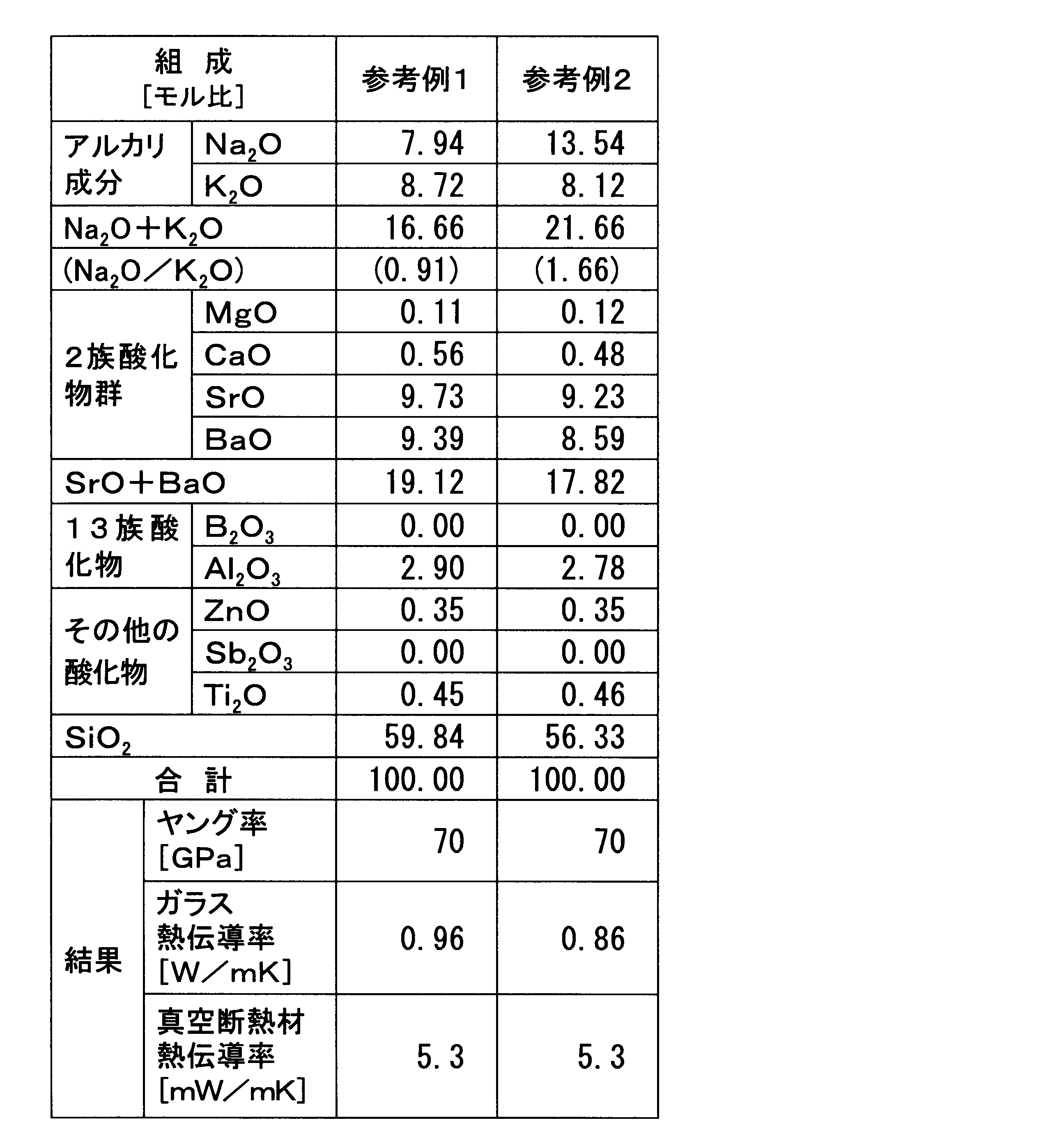
(実施例1~6および参考例1、2の対比)
参考例1および2は、第一組成条件および副組成条件を満たしているため、本発明における実施例に相当するが、ここでは、実施例2~6に対する比較のための実施例として位置づけているため「参考例」として取り扱う。 (Contrast of Examples 1 to 6 and Reference Examples 1 and 2)
Since Reference Examples 1 and 2 satisfy the first composition condition and the sub-composition condition, they correspond to Examples in the present invention, but are positioned here as examples for comparison with Examples 2 to 6. Therefore, it is handled as a “reference example”.
これら参考例の参考真空断熱材は、実施例1と同等の熱伝導率を有しており、また、ガラス素材の熱伝導率についても、実施例2~6と同等かそれ以下の値を示している。それゆえ、第一組成条件および副組成条件を満たしていれば、良好な断熱性を実現することができることがわかる。ただし、第二組成条件を満たしていない(参考例1、2では、下位条件3を満たしていない)場合には、ガラス素材のヤング率が71GPa未満となるため、前述した性質条件のうち(3)剛性条件を満たすことができないことがわかる。
The reference vacuum heat insulating materials of these reference examples have the thermal conductivity equivalent to that of Example 1, and the thermal conductivity of the glass material also shows a value equivalent to or lower than that of Examples 2 to 6. ing. Therefore, it can be seen that good heat insulation can be realized if the first composition condition and the sub-composition condition are satisfied. However, when the second composition condition is not satisfied (in Reference Examples 1 and 2, the lower condition 3 is not satisfied), the Young's modulus of the glass material is less than 71 GPa. It can be seen that the rigidity condition cannot be satisfied.
なお、上記説明から、当業者にとっては、本発明の多くの改良や他の実施形態が明らかである。従って、上記説明は、例示としてのみ解釈されるべきであり、本発明を実行する最良の態様を当業者に教示する目的で提供されたものである。本発明の精神を逸脱することなく、その構造及び/又は機能の詳細を実質的に変更できる。
It should be noted that many improvements and other embodiments of the present invention will be apparent to those skilled in the art from the above description. Accordingly, the foregoing description should be construed as illustrative only and is provided for the purpose of teaching those skilled in the art the best mode of carrying out the invention. The details of the structure and / or function may be substantially changed without departing from the spirit of the invention.
本発明は、芯材の熱伝導を低減して優れた断熱性を発揮できるので、断熱を目的とするさまざまな分野に広く用いることができ、特に、冷凍冷蔵庫、住宅壁等のようにさらなる省エネルギー化が要求される分野に好適に用いることができる。
Since the present invention can exhibit excellent heat insulation by reducing the heat conduction of the core material, it can be widely used in various fields for the purpose of heat insulation, and in particular, further energy saving such as a refrigerator-freezer, a housing wall, etc. It can be suitably used in a field that needs to be realized.
10 真空断熱材
11 芯材
12 外包材
20 冷凍冷蔵庫
20b (冷凍冷蔵庫の)側面
20c (冷凍冷蔵庫の)背面
21 外箱
22 内箱
30 住宅壁
31 耐力壁
31b (耐力壁の)裏面 DESCRIPTION OF SYMBOLS 10 Vacuum heat insulating material 11 Core material 12 Outer packaging material 20 Refrigerating refrigerator 20b (Frozen refrigerator) side surface 20c (Frozen refrigerator) back surface 21 Outer box 22 Inner box 30 Residential wall 31 Load bearing wall 31b (Load bearing wall) back surface
Claims (16)
- 断熱性を有する芯材と、
ガスバリア性を有し、前記芯材を減圧密閉状態で内部に封入する外包材と、を備え、
前記芯材は、
少なくとも、CaO含有量が5モル%以下であって、疎水性を有し、
その繊維表面の十点平均粗さRzが30以上であり、
SrOおよびBaOの含有量が16モル%以上、かつ、K2O の含有量が7モル%以上、かつ、B2O3の含有量が4モル%以上である、
ガラス繊維から構成されている、
真空断熱材。 A heat-insulating core material;
An outer packaging material having a gas barrier property and enclosing the core material in a sealed state under reduced pressure,
The core material is
At least the CaO content is 5 mol% or less and has hydrophobicity,
The ten-point average roughness Rz of the fiber surface is 30 or more,
SrO and BaO content is 16 mol% or more, and K 2 O content 7 mol% or more and the content of B 2 O 3 is 4 mol% or more,
Composed of glass fiber,
Vacuum insulation. - 断熱性を有する芯材と、
ガスバリア性を有し、前記芯材を減圧密閉状態で内部に封入する外包材と、を備え、
前記芯材は、少なくとも、CaO含有量が5モル%以下であって、疎水性を有するガラス繊維から構成されている、
真空断熱材。 A heat-insulating core material;
An outer packaging material having a gas barrier property and enclosing the core material in a sealed state under reduced pressure,
The core material is composed of glass fibers having at least a CaO content of 5 mol% or less and having hydrophobicity,
Vacuum insulation. - 断熱性を有する芯材と、
ガスバリア性を有し、前記芯材を減圧密閉状態で内部に封入する外包材と、を備え、
前記芯材は、その繊維表面の十点平均粗さRzが30以上のガラス繊維から構成されている、
真空断熱材。 A heat-insulating core material;
An outer packaging material having a gas barrier property and enclosing the core material in a sealed state under reduced pressure,
The core material is composed of glass fibers having a ten-point average roughness Rz of 30 or more on the fiber surface.
Vacuum insulation. - 断熱性を有する芯材と、
ガスバリア性を有し、前記芯材を減圧密閉状態で内部に封入する外包材と、を備え、
前記芯材は、SrOおよびBaOの含有量が16モル%以上、かつ、K2O の含有量が7モル%以上、かつ、B2O3の含有量が4モル%以上であるガラス繊維から構成されている、
真空断熱材。 A heat-insulating core material;
An outer packaging material having a gas barrier property and enclosing the core material in a sealed state under reduced pressure,
The core material, SrO and BaO content is 16 mol% or more, and K 2 O content 7 mol% or more, and a glass fiber content of B 2 O 3 is 4 mol% or more It is configured,
Vacuum insulation. - 前記ガラス繊維は、JIS R3502に基づくアルカリ溶出量が300μg/g以下である、
請求項2に記載の真空断熱材。 The glass fiber has an alkali elution amount based on JIS R3502 of 300 μg / g or less.
The vacuum heat insulating material according to claim 2. - 前記ガラス繊維は、平均径が0.1~10μmの範囲内であり、
前記芯材は、前記ガラス繊維を伝熱方向に対して交差する方向に配向させるよう構成されていることを特徴とする、
請求項3に記載の真空断熱材。 The glass fiber has an average diameter in the range of 0.1 to 10 μm,
The core material is configured to orient the glass fibers in a direction intersecting the heat transfer direction,
The vacuum heat insulating material according to claim 3. - 前記ガラス繊維は、SrO、BaO、およびMgOの少なくとも何れかを含有する、
請求項2または3に記載の真空断熱材。 The glass fiber contains at least one of SrO, BaO, and MgO.
The vacuum heat insulating material according to claim 2 or 3. - 前記ガラス繊維は、
前記SrOを含有する場合には、その含有量が1~12モル%の範囲内であり、
前記BaOを含有する場合には、その含有量が1~8モル%の範囲内であり、
前記MgOを含有する場合には、その含有量が5~12モル%の範囲内である、
請求項7に記載の真空断熱材。 The glass fiber is
When it contains SrO, its content is in the range of 1 to 12 mol%,
When it contains BaO, its content is in the range of 1 to 8 mol%,
When it contains MgO, its content is in the range of 5 to 12 mol%,
The vacuum heat insulating material according to claim 7. - 前記ガラス繊維を構成するガラス素材のヤング率が71GPa以上である、
請求項4に記載の真空断熱材。 The Young's modulus of the glass material constituting the glass fiber is 71 GPa or more.
The vacuum heat insulating material according to claim 4. - 前記芯材の空隙率は90%以上である、
請求項1から9のいずれか1項に記載の真空断熱材。 The core has a porosity of 90% or more.
The vacuum heat insulating material of any one of Claim 1 to 9. - 前記ガラス繊維を構成するガラス素材の熱伝導率が1W/mK以下である、
請求項1から10のいずれか1項に記載の真空断熱材。 The thermal conductivity of the glass material constituting the glass fiber is 1 W / mK or less,
The vacuum heat insulating material according to any one of claims 1 to 10. - 前記ガラス繊維は、その原料にブラウン管ガラスを用いて製造されたものである、
請求項1から11のいずれか1項に記載の真空断熱材。 The glass fiber is manufactured using CRT glass as its raw material,
The vacuum heat insulating material according to any one of claims 1 to 11. - 請求項1から12のいずれか1項に記載の真空断熱材と、
外部筐体となる外箱と、
当該外箱内に位置し、その内部が物品を収納する収納空間となっている内箱と、を備え、
前記外箱と前記内箱との間に、前記真空断熱材が配されている、
冷凍冷蔵庫。 The vacuum heat insulating material according to any one of claims 1 to 12,
An outer box as an external housing;
An inner box located in the outer box, the inside of which is a storage space for storing articles,
The vacuum heat insulating material is arranged between the outer box and the inner box,
Freezer refrigerator. - 前記真空断熱材は、前記外箱および前記内箱の間であって、前記冷凍冷蔵庫の左右の側面および背面の少なくともいずれかとなる位置に配されている、
請求項13に記載の冷凍冷蔵庫。 The vacuum heat insulating material is disposed between the outer box and the inner box at a position that is at least one of the left and right side surfaces and the back surface of the refrigerator-freezer.
The refrigerator-freezer of Claim 13. - 請求項1から12のいずれか1項に記載の真空断熱材と、
耐力壁と、を備え、
前記耐力壁の裏面側に前記真空断熱材が配されている、
住宅壁。 The vacuum heat insulating material according to any one of claims 1 to 12,
Bearing walls, and
The vacuum heat insulating material is disposed on the back side of the load bearing wall,
Residential wall. - 前記耐力壁の裏面に前記真空断熱材が固定されて構成される断熱パネル材である、
請求項15に記載の住宅壁。
The heat insulating panel material is configured by fixing the vacuum heat insulating material to the back surface of the load bearing wall.
The residential wall according to claim 15.
Applications Claiming Priority (8)
| Application Number | Priority Date | Filing Date | Title |
|---|---|---|---|
| JP2012090477 | 2012-04-11 | ||
| JP2012090478 | 2012-04-11 | ||
| JP2012-090479 | 2012-04-11 | ||
| JP2012-090477 | 2012-04-11 | ||
| JP2012-090478 | 2012-04-11 | ||
| JP2012090479 | 2012-04-11 | ||
| JP2012090476 | 2012-04-11 | ||
| JP2012-090476 | 2012-04-11 |
Publications (1)
| Publication Number | Publication Date |
|---|---|
| WO2013153813A1 true WO2013153813A1 (en) | 2013-10-17 |
Family
ID=49327397
Family Applications (1)
| Application Number | Title | Priority Date | Filing Date |
|---|---|---|---|
| PCT/JP2013/002464 WO2013153813A1 (en) | 2012-04-11 | 2013-04-11 | Vacuum heat insulator, and refrigerator-freezer and home wall provided with same |
Country Status (1)
| Country | Link |
|---|---|
| WO (1) | WO2013153813A1 (en) |
Cited By (2)
| Publication number | Priority date | Publication date | Assignee | Title |
|---|---|---|---|---|
| JP6359206B1 (en) * | 2016-11-10 | 2018-07-18 | 三菱電機株式会社 | Vacuum heat insulating material, vacuum heat insulating material manufacturing method, and vacuum heat insulating material manufacturing apparatus |
| CN111336346A (en) * | 2018-12-19 | 2020-06-26 | 广州力及热管理科技有限公司 | Method for manufacturing thin vacuum heat insulation sheet with supporting structure |
Citations (5)
| Publication number | Priority date | Publication date | Assignee | Title |
|---|---|---|---|---|
| JPS55140735A (en) * | 1979-03-15 | 1980-11-04 | Pilkington Brothers Ltd | Alkali resistant glass fiber |
| JP2001064036A (en) * | 1999-08-27 | 2001-03-13 | Asahi Glass Co Ltd | Water-resistant glass having flame retardant function and flame retardant resin composition |
| JP2006038123A (en) * | 2004-07-28 | 2006-02-09 | Matsushita Electric Ind Co Ltd | Vacuum thermal insulation material and glass composition |
| JP2008286263A (en) * | 2007-05-16 | 2008-11-27 | Panasonic Corp | Vacuum heat insulation material |
| JP2009264569A (en) * | 2008-04-30 | 2009-11-12 | Panasonic Corp | Vacuum heat insulating material |
-
2013
- 2013-04-11 WO PCT/JP2013/002464 patent/WO2013153813A1/en active Application Filing
Patent Citations (5)
| Publication number | Priority date | Publication date | Assignee | Title |
|---|---|---|---|---|
| JPS55140735A (en) * | 1979-03-15 | 1980-11-04 | Pilkington Brothers Ltd | Alkali resistant glass fiber |
| JP2001064036A (en) * | 1999-08-27 | 2001-03-13 | Asahi Glass Co Ltd | Water-resistant glass having flame retardant function and flame retardant resin composition |
| JP2006038123A (en) * | 2004-07-28 | 2006-02-09 | Matsushita Electric Ind Co Ltd | Vacuum thermal insulation material and glass composition |
| JP2008286263A (en) * | 2007-05-16 | 2008-11-27 | Panasonic Corp | Vacuum heat insulation material |
| JP2009264569A (en) * | 2008-04-30 | 2009-11-12 | Panasonic Corp | Vacuum heat insulating material |
Cited By (2)
| Publication number | Priority date | Publication date | Assignee | Title |
|---|---|---|---|---|
| JP6359206B1 (en) * | 2016-11-10 | 2018-07-18 | 三菱電機株式会社 | Vacuum heat insulating material, vacuum heat insulating material manufacturing method, and vacuum heat insulating material manufacturing apparatus |
| CN111336346A (en) * | 2018-12-19 | 2020-06-26 | 广州力及热管理科技有限公司 | Method for manufacturing thin vacuum heat insulation sheet with supporting structure |
Similar Documents
| Publication | Publication Date | Title |
|---|---|---|
| KR100507783B1 (en) | Heat insulation box, and vacuum heat insulation material used therefor | |
| EP1510747B1 (en) | Vacuum thermal insulating material, process for producing the same and refrigerator including the same | |
| KR101164306B1 (en) | Vacuum heat insulating material, heat-insulating box body using the same and refrigerator | |
| JP5798942B2 (en) | Vacuum heat insulating material and refrigerator and equipment using the same | |
| EP2554759A2 (en) | High-performance vacuum insulation panel and manufacturing method thereof | |
| US9404684B2 (en) | Vacuum insulation panel and refrigerator including the same | |
| KR101560355B1 (en) | Vacuum insulation material, refrigerator, equipment using vacuum insulation material | |
| WO2013153813A1 (en) | Vacuum heat insulator, and refrigerator-freezer and home wall provided with same | |
| JP5548025B2 (en) | Vacuum heat insulating material and refrigerator using the same | |
| JP4997198B2 (en) | Vacuum heat insulating material, heat insulating box using the same, and refrigerator | |
| JP2011174550A (en) | Vacuum heat insulation material and equipment using the same | |
| JP3488229B2 (en) | Insulated box and refrigerator | |
| JP6486079B2 (en) | Method for maintaining heat insulation performance of vacuum insulation panel and method for maintaining heat insulation performance of refrigerator | |
| JP5982211B2 (en) | Vacuum insulation, refrigerator, equipment using vacuum insulation | |
| JP5953159B2 (en) | Vacuum insulation and refrigerator | |
| JP3527727B2 (en) | Vacuum insulation material and equipment using the vacuum insulation material | |
| JP6778774B2 (en) | Manufacturing method of vacuum insulation panel | |
| AU2004233499B2 (en) | Refrigerator | |
| JP2008208845A (en) | Composite heat insulating material | |
| KR20150066451A (en) | Vacuum Insulation Material | |
| JP2014119079A (en) | Vacuum insulation material and refrigerator using vacuum insulation material |
Legal Events
| Date | Code | Title | Description |
|---|---|---|---|
| 121 | Ep: the epo has been informed by wipo that ep was designated in this application |
Ref document number: 13776251 Country of ref document: EP Kind code of ref document: A1 |
|
| NENP | Non-entry into the national phase |
Ref country code: DE |
|
| 122 | Ep: pct application non-entry in european phase |
Ref document number: 13776251 Country of ref document: EP Kind code of ref document: A1 |
|
| NENP | Non-entry into the national phase |
Ref country code: JP |