WO2013153588A1 - Battery, battery pack, and vehicle - Google Patents
Battery, battery pack, and vehicle Download PDFInfo
- Publication number
- WO2013153588A1 WO2013153588A1 PCT/JP2012/007880 JP2012007880W WO2013153588A1 WO 2013153588 A1 WO2013153588 A1 WO 2013153588A1 JP 2012007880 W JP2012007880 W JP 2012007880W WO 2013153588 A1 WO2013153588 A1 WO 2013153588A1
- Authority
- WO
- WIPO (PCT)
- Prior art keywords
- battery
- case
- unit cell
- unit
- cell
- Prior art date
Links
Images


Classifications
-
- H—ELECTRICITY
- H01—ELECTRIC ELEMENTS
- H01M—PROCESSES OR MEANS, e.g. BATTERIES, FOR THE DIRECT CONVERSION OF CHEMICAL ENERGY INTO ELECTRICAL ENERGY
- H01M10/00—Secondary cells; Manufacture thereof
- H01M10/42—Methods or arrangements for servicing or maintenance of secondary cells or secondary half-cells
- H01M10/48—Accumulators combined with arrangements for measuring, testing or indicating the condition of cells, e.g. the level or density of the electrolyte
-
- H—ELECTRICITY
- H01—ELECTRIC ELEMENTS
- H01M—PROCESSES OR MEANS, e.g. BATTERIES, FOR THE DIRECT CONVERSION OF CHEMICAL ENERGY INTO ELECTRICAL ENERGY
- H01M10/00—Secondary cells; Manufacture thereof
- H01M10/60—Heating or cooling; Temperature control
- H01M10/65—Means for temperature control structurally associated with the cells
- H01M10/655—Solid structures for heat exchange or heat conduction
- H01M10/6556—Solid parts with flow channel passages or pipes for heat exchange
-
- H—ELECTRICITY
- H01—ELECTRIC ELEMENTS
- H01M—PROCESSES OR MEANS, e.g. BATTERIES, FOR THE DIRECT CONVERSION OF CHEMICAL ENERGY INTO ELECTRICAL ENERGY
- H01M50/00—Constructional details or processes of manufacture of the non-active parts of electrochemical cells other than fuel cells, e.g. hybrid cells
- H01M50/10—Primary casings, jackets or wrappings of a single cell or a single battery
- H01M50/102—Primary casings, jackets or wrappings of a single cell or a single battery characterised by their shape or physical structure
- H01M50/105—Pouches or flexible bags
-
- H—ELECTRICITY
- H01—ELECTRIC ELEMENTS
- H01M—PROCESSES OR MEANS, e.g. BATTERIES, FOR THE DIRECT CONVERSION OF CHEMICAL ENERGY INTO ELECTRICAL ENERGY
- H01M50/00—Constructional details or processes of manufacture of the non-active parts of electrochemical cells other than fuel cells, e.g. hybrid cells
- H01M50/20—Mountings; Secondary casings or frames; Racks, modules or packs; Suspension devices; Shock absorbers; Transport or carrying devices; Holders
- H01M50/204—Racks, modules or packs for multiple batteries or multiple cells
- H01M50/207—Racks, modules or packs for multiple batteries or multiple cells characterised by their shape
- H01M50/211—Racks, modules or packs for multiple batteries or multiple cells characterised by their shape adapted for pouch cells
-
- H—ELECTRICITY
- H01—ELECTRIC ELEMENTS
- H01M—PROCESSES OR MEANS, e.g. BATTERIES, FOR THE DIRECT CONVERSION OF CHEMICAL ENERGY INTO ELECTRICAL ENERGY
- H01M50/00—Constructional details or processes of manufacture of the non-active parts of electrochemical cells other than fuel cells, e.g. hybrid cells
- H01M50/20—Mountings; Secondary casings or frames; Racks, modules or packs; Suspension devices; Shock absorbers; Transport or carrying devices; Holders
- H01M50/218—Mountings; Secondary casings or frames; Racks, modules or packs; Suspension devices; Shock absorbers; Transport or carrying devices; Holders characterised by the material
- H01M50/22—Mountings; Secondary casings or frames; Racks, modules or packs; Suspension devices; Shock absorbers; Transport or carrying devices; Holders characterised by the material of the casings or racks
- H01M50/222—Inorganic material
- H01M50/224—Metals
-
- H—ELECTRICITY
- H01—ELECTRIC ELEMENTS
- H01M—PROCESSES OR MEANS, e.g. BATTERIES, FOR THE DIRECT CONVERSION OF CHEMICAL ENERGY INTO ELECTRICAL ENERGY
- H01M50/00—Constructional details or processes of manufacture of the non-active parts of electrochemical cells other than fuel cells, e.g. hybrid cells
- H01M50/50—Current conducting connections for cells or batteries
- H01M50/502—Interconnectors for connecting terminals of adjacent batteries; Interconnectors for connecting cells outside a battery casing
- H01M50/507—Interconnectors for connecting terminals of adjacent batteries; Interconnectors for connecting cells outside a battery casing comprising an arrangement of two or more busbars within a container structure, e.g. busbar modules
-
- H—ELECTRICITY
- H01—ELECTRIC ELEMENTS
- H01M—PROCESSES OR MEANS, e.g. BATTERIES, FOR THE DIRECT CONVERSION OF CHEMICAL ENERGY INTO ELECTRICAL ENERGY
- H01M50/00—Constructional details or processes of manufacture of the non-active parts of electrochemical cells other than fuel cells, e.g. hybrid cells
- H01M50/50—Current conducting connections for cells or batteries
- H01M50/569—Constructional details of current conducting connections for detecting conditions inside cells or batteries, e.g. details of voltage sensing terminals
-
- H—ELECTRICITY
- H01—ELECTRIC ELEMENTS
- H01M—PROCESSES OR MEANS, e.g. BATTERIES, FOR THE DIRECT CONVERSION OF CHEMICAL ENERGY INTO ELECTRICAL ENERGY
- H01M10/00—Secondary cells; Manufacture thereof
- H01M10/60—Heating or cooling; Temperature control
- H01M10/62—Heating or cooling; Temperature control specially adapted for specific applications
- H01M10/625—Vehicles
-
- H—ELECTRICITY
- H01—ELECTRIC ELEMENTS
- H01M—PROCESSES OR MEANS, e.g. BATTERIES, FOR THE DIRECT CONVERSION OF CHEMICAL ENERGY INTO ELECTRICAL ENERGY
- H01M2220/00—Batteries for particular applications
- H01M2220/20—Batteries in motive systems, e.g. vehicle, ship, plane
-
- Y—GENERAL TAGGING OF NEW TECHNOLOGICAL DEVELOPMENTS; GENERAL TAGGING OF CROSS-SECTIONAL TECHNOLOGIES SPANNING OVER SEVERAL SECTIONS OF THE IPC; TECHNICAL SUBJECTS COVERED BY FORMER USPC CROSS-REFERENCE ART COLLECTIONS [XRACs] AND DIGESTS
- Y02—TECHNOLOGIES OR APPLICATIONS FOR MITIGATION OR ADAPTATION AGAINST CLIMATE CHANGE
- Y02E—REDUCTION OF GREENHOUSE GAS [GHG] EMISSIONS, RELATED TO ENERGY GENERATION, TRANSMISSION OR DISTRIBUTION
- Y02E60/00—Enabling technologies; Technologies with a potential or indirect contribution to GHG emissions mitigation
- Y02E60/10—Energy storage using batteries
Definitions
- the present invention relates to a battery structure in which a power generation unit is housed in a case.
- Patent Document 1 discloses a battery in which both ends of a flat wound body in which a sheet-shaped power generation unit is wound around an axis are suspended and supported in a case. Thus, the winding body is positioned at a predetermined position in the case by suspending and supporting the winding body in the case.
- the above-described configuration requires a support member for supporting the wound body in a suspended manner, so that the battery is increased in size.
- an object of the present invention is to suppress the displacement of the power generation unit in the case while suppressing the increase in size of the battery.
- a battery according to the present invention includes (1) a power generation unit in which a single cell is covered with an insulating exterior material, and a sealed structure case that houses the power generation unit, In the case, the internal pressure is higher than the external pressure.
- the power generation unit is a battery module in which a battery group in which the single cells are arranged is covered with the exterior material, and the battery module connects the adjacent single cells. It can be accommodated in the case in a folded state in the region where the conductive member is located. According to the configuration of (2), it is possible to more effectively suppress the positional deviation of each single cell in the case while suppressing the increase in size of the battery.
- a refrigerant passage for conducting the refrigerant can be provided along the surface of the case closest to the conductive member. According to the structure of (3), since the area
- the case includes a first side surface facing each other in a first direction and a second side facing each other in a second direction orthogonal to the first direction.
- a pair of extraction electrodes having a side surface, a bottom surface, and a top surface for extracting the power of the battery module to the outside of the case are provided on the top surface side, and are included in the battery group.
- the number of single cells is an even number, and in the battery group, the end on the top surface side is connected to the one extraction electrode via a first connection member, and the end on the bottom surface side is the conductive member.
- the battery group further includes a third unit cell connected to the first unit cell through the conductive member, and the third unit cell through the conductive member.
- a fourth unit cell connected to the unit cell, wherein the first connection member is connected to one of the positive electrode and the negative electrode of the first unit cell, and the conductive member is The first voltage detection unit exposed to the outside of the exterior material and connected to the other electrode of the first unit cell is connected to the third unit cell and the fourth unit cell.
- a second voltage detector connected to the exposed portion of the conductive member.
- the first voltage detection unit can be connected to an end portion on the top surface side of the first unit cell.
- An assembled battery including a plurality of the batteries according to any one of (4) to (6), wherein each of the pair of extraction electrodes of each of the unit cells is arranged in the first direction. It is out.
- the battery described in any one of (1) to (6) above can be mounted on a vehicle.
- the motor for driving the vehicle is driven by the electric power supplied from the battery.
- the assembled battery according to (7) can be mounted on a vehicle.
- the motor for driving the vehicle is driven by the electric power supplied from the assembled battery.
- An object of the present invention is to suppress the displacement of the power generation element in the case while suppressing the increase in size of the battery.
- FIG. 2 is a cross-sectional view of the battery module of FIG. 1 cut along a section XX ′. It is a perspective view of the battery in which the battery module was accommodated.
- FIG. 4 is a cross-sectional view of the battery of FIG. 3 cut along a TT ′ cross section. It is operation
- FIG. 10 is an assembly diagram of an assembled battery of Modification 3. It is the schematic which illustrated the modification of the battery case. It is the schematic which illustrated another modification of the battery case.
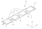
- FIG. 1 is a development view of a battery module (corresponding to a power generation unit).
- X axis, Y axis and Z axis are three axes orthogonal to each other, X axis corresponds to the direction orthogonal to the longitudinal direction of the battery module, Y axis corresponds to the longitudinal direction of the battery module, Z The axis corresponds to the thickness direction of the battery module.
- FIG. 2 is a cross-sectional view of the battery module taken along the line XX ′ of FIG.
- FIG. 3 is an external perspective view of a battery in which a battery module is incorporated.
- T1 axis, T2 axis and T3 axis are three axes orthogonal to each other.
- FIG. 4 is a cross-sectional view of the battery of FIG. 3 cut along the TT ′ cross section.
- a battery module 10 includes a battery group 11, an inter-cell connection tab (corresponding to a conductive member) 12a, a positive terminal connecting tab 12b (corresponding to a first connecting member), a negative electrode A terminal connection tab 12c (secondly corresponding to a connection member) and an exterior material 13 are included.
- the battery group 11 includes a first cell 11a, a second cell 11b, a third cell 11c, and a fourth cell 11d. These first to fourth unit cells 11 a to 11 d are arranged in the Y-axis direction, which is the longitudinal direction of the exterior member 13. However, the number of unit cells 11 may be 1 to 3, or 5 or more.
- the first unit cell 11a is located at one end in the Y-axis direction
- the second unit cell 11b is located at the other end in the Y-axis direction.
- the exterior material 13 is composed of film members 13a and 13b. These film members 13a and 13b sandwich the first to fourth unit cells 11a to 11d and are heat-sealed to each other in the outer edge region. The first to fourth unit cells 11a to 11d are hermetically sealed in the exterior member 13 by heat-sealing the film members 13a and 13b. Note that the inter-cell connection tab 12 a may be exposed to the outside of the exterior material 13.
- the film members 13a and 13b flexible sheets having insulating properties can be used.
- the film members 13a and 13b may be laminate films.
- the first to fourth unit cells 11a to 11d can be unitized as one battery module.
- the first unit cell 11a includes a positive electrode body 111a, a negative electrode body 111b, and a separator 111c, and the positive electrode body 111a and the negative electrode body 111b are stacked via the separator 111c.
- the direction in which the positive electrode body 111a, the negative electrode body 111b, and the separator 111c are stacked may be referred to as a stacking direction.
- the first to fourth unit cells 11a to 11d may be secondary batteries such as nickel metal hydride batteries and lithium ion batteries, or capacitors. In FIG. 2, some of the positive electrode body 111a, the negative electrode body 111b, and the separator 111c are omitted.
- the positive electrode body 111a includes a current collector and a positive electrode layer formed on the surface of the current collector.
- the positive electrode layer includes a positive electrode active material, a conductive agent, and the like.
- the positive electrode active material Li ⁇ Co-based composite oxide such as LiCoO 2, Li ⁇ Ni-based composite oxide such as LiNiO 2, Li ⁇ Mn-based composite oxide such as spinel LiMn 2 O 4, Li ⁇ such LiFeO 2 Fe-based composite oxides may also be used.
- the positive electrode active material includes transition metal and lithium phosphate compounds and sulfuric acid compounds such as LiFePO 4 , transition metal oxides and sulfides such as V 2 O 5 , MnO 2 , TiS 2 , MoS 2 , and MoO 3 , PbO 2 , AgO, NiOOH.
- the negative electrode body 111b includes a current collector and a negative electrode layer formed on the surface of the current collector.
- the negative electrode layer includes a negative electrode active material, a conductive agent, and the like.
- the negative electrode active material may be a metal oxide, a lithium-metal composite oxide, or carbon.
- the positive electrode terminal connection tab 12b is connected to one end of the first unit cell 11a in the stacking direction.
- the positive electrode terminal connection tab 12 b is connected to the total positive terminal 21 (corresponding to the extraction electrode) of the battery 1.
- the method of connecting the positive terminal connecting tab 12b and the total plus terminal 21 may be ultrasonic welding or spot welding.
- the negative electrode terminal connection tab 12c is connected to one end of the second unit cell 11b in the stacking direction.
- the negative electrode terminal connection tab 12c is connected to the total negative terminal 22 (corresponding to the extraction electrode) of the battery 1.
- the method for connecting the negative terminal connecting tab 12c and the total minus terminal 22 may be ultrasonic welding or spot welding.
- the electrolyte may be a solid electrolyte or an electrolytic solution.
- a polymer solid electrolyte or an inorganic solid electrolyte can be used.
- the polymer solid electrolyte for example, polyethylene oxide (PEO), polypropylene oxide (PPO), or a copolymer thereof can be used.
- the polymer solid electrolyte may contain a lithium salt in order to ensure ion conductivity.
- the lithium salt for example, LiBF 4 , LiPF 6 , LiN (SO 2 CF 3 ) 2 , LiN (SO 2 C 2 F 5 ) 2 , or a mixture thereof can be used.
- the battery case 30 has a pair of first case side surfaces 30a facing each other in the T3 axis (corresponding to the first direction) and a pair of second cases facing each other in the T1 axis (corresponding to the second direction). It includes a case side surface 30b, a case bottom surface 30c, and a case top surface 30d. In FIG. 3, the case top surface 30d is omitted.
- the case main body composed of the first case side surface 30a, the second case side surface 30b, and the case bottom surface 30c, and the case bottom surface 30d can be manufactured separately.
- the case body can be manufactured, for example, by press molding.
- the case top surface 30d can be fixed by welding to the inner surfaces of the first case side surface 30a and the second case side surface 30b.
- a metal can be used for the battery case 30.
- the battery module 10 is bent at the bent portion 10a.
- the bent portion 10a is formed in an intermediate portion between adjacent unit cells, that is, a region where the inter-unit cell connection tab 12a connecting the adjacent unit cells is located.
- the end on the case top surface 30d side is connected to the total plus terminal 21 via the positive terminal connecting tab 12b, and the end on the case bottom surface 30c side is connected to the inter-cell connection tab 12a. It is connected to the third cell 11c.
- the end on the case top surface 30d side is connected to the total minus terminal 22 via the negative electrode terminal connection tab 12c, and the end on the case bottom surface 30c side is connected to the inter-cell connection tab 12a. It is connected to the fourth unit cell 11d.
- the space inside the battery case 30 can be used effectively. Thereby, the enlargement of the battery 1 is suppressed.
- the number of single cells constituting the battery group 11 is set to an even number, and the battery module 10 is housed in a folded state inside the battery case 30 so that the total positive terminal 21 and the positive terminal are connected.
- part of the 1st cell 11a to which the part 12b is connected can be made small. Thereby, the length of the positive electrode terminal connection part 12b can be made small.
- the interval between the total negative terminal 22 and the connection portion of the second unit cell 11b to which the negative terminal connection portion 12c is connected can be reduced. Thereby, the length of the negative electrode terminal connection part 12c can be made small.
- a cooling duct 31 is provided on the case bottom surface 30c.
- the cooling duct 31 includes cooling fins 31a and duct wall portions 31b.
- the cooling fins 31a are in contact with the case bottom surface 30c and are provided at predetermined intervals in the longitudinal direction (T1-axis direction) of the case bottom surface 30c.
- a metal having high thermal conductivity can be used for the cooling fin 31a.
- the metal may be aluminum.
- FIG. 5 is a diagram for explaining the operation of the processing apparatus for processing the cooling fin, and it is assumed that the processing proceeds in the order of (a) to (e).
- An impact molding apparatus can be used as the processing apparatus.
- the impact processing apparatus includes a punch 81 and a die 82.
- the punch 81 advances and retreats with respect to the concave portion of the die 82.
- the punch 81 is driven by a motor (not shown).
- the slag M serving as a base material for the cooling fin is placed in the recess of the die 82.
- the slag M may be a cylindrical ingot made of aluminum.
- the cooling fin 31a can be easily manufactured simply by lowering the punch 81 toward the die 82. Moreover, the cost of the mold is reduced, and an increase in the manufacturing cost of the battery 1 can be suppressed.
- a refrigerant path for conducting the refrigerant is formed by the space surrounded by the case bottom surface 30c, the cooling fin 31a, and the duct wall portion 31b.
- the case bottom surface 30c is cooled by the refrigerant flowing in the refrigerant path, and the battery module 10 can be further cooled. As a result, the deterioration of the first to fourth unit cells 11a to 11d is suppressed.
- the refrigerant may be air or a liquid heat exchange medium.
- the bent portion 10a when the battery module 10 is charged / discharged, the bent portion 10a may have a temperature higher than that of other portions. That is, since the inter-cell connection tab 12a is located in the bent portion 10a, the heat generation temperature when the battery module 10 is charged and discharged is relatively high.
- the bent portion 10a is in contact with the case bottom surface 30c, and since the cooling fins 31a are in contact with the case bottom surface 30c, the first to fourth unit cells 11a to 11d are cooled by the refrigerant flowing inside the cooling duct 31. Can be efficiently cooled.
- the internal pressure of the battery case 30 is set higher than the external pressure.
- the method of increasing the internal pressure of the battery case 30 may be a method of supplying an inert gas (for example, nitrogen gas) or air into the battery case 30.
- an inert gas for example, nitrogen gas
- air By sending an inert gas or the like into the battery case 30, the inside of the battery case 30 becomes a pressurized atmosphere, and the battery module 10 is pressed against the inner surface of the battery case 30.
- the displacement of the battery module 10 is suppressed.
- the displacement of the battery module 10 it is possible to suppress the exterior material 13 of the battery module 10 from sliding on the inner wall of the battery case 30 and wearing.
- the positive electrode body 111a, the negative electrode body 111b, and the separator 111c which are power generation elements of the unit cell, are more firmly adhered to each other, so that a decrease in input / output characteristics of the battery module 10 can be suppressed.
- the battery module 10 can be restrained without a restraining member. Thereby, increase in cost can be suppressed, suppressing complication of assembly work.
- the battery module 10 Since the battery module 10 is restrained by the internal pressure of the battery case 30, a support member for supporting the battery module 10 in a suspended manner inside the battery case 30 can be omitted. Thereby, since the space for arranging the battery module 10 in the battery case 30 increases, the size of the battery module 10 can be increased while suppressing an increase in the size of the battery 1.
- gas may be released from the first to fourth unit cells 11a to 11d, and the internal pressure of the gas exterior member 13 may increase.
- the gas exterior material 13 is pressurized from the outside by the pressure inside the battery case 30, it is possible to suppress the outflow of gas from the exterior material 13.
- the exterior material 13 of the battery module 10 is insulative and the battery case 30 has no potential, it is not necessary to insulate the inner surface of the battery case 30. Thereby, cost can be reduced.
- a laminate film containing aluminium is widely known as a material used for sealing a unit cell. Since the laminate film containing aluminum has water-stopping properties, moisture can be prevented from entering the inside of the unit cell.
- the battery case 30 is comprised with the metal, and it can suppress that a water
- the battery 1 described above can be mounted on a vehicle.
- the battery 1 supplies electric power to a vehicle running motor.
- the motor rotates with the electric power supplied from the battery 1 to drive the vehicle.
- the vehicle may be an electric vehicle having only the battery 1 as a power source for driving the vehicle, or a hybrid vehicle having both the battery 1 and another element (for example, an internal combustion engine, a fuel cell) as a power source.
- the hybrid vehicle includes a plug-in hybrid vehicle that can charge the battery 1 by a power source outside the vehicle.
- an assembled battery A in which a plurality of batteries 1 are connected may be mounted on the vehicle. The assembled battery A causes the vehicle to travel by supplying electric power to a motor for traveling the vehicle.
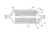
- FIG. 6 is a development view of the battery module (corresponding to the power generation unit) 100.
- FIG. 7 is a cross-sectional view of the battery corresponding to FIG.
- the battery module 100 includes a first unit cell 51, a second unit cell 52, a third unit cell 53, and a fourth unit cell 54.
- the first cell 51 is located at one end of the battery module 100, and the second cell 52 is located at the other end of the battery module 100.
- the first unit cell 51 is configured by laminating a positive electrode body 51a and a negative electrode body 51b with a separator interposed therebetween. Since the positive electrode body 51a and the negative electrode body 51b have the same configurations as the positive electrode body 111a and the negative electrode body 111b of the first embodiment, detailed description thereof will be omitted. Further, the second to fourth unit cells 54 have the same configuration as the first unit cell 51, and thus detailed description thereof is omitted.
- the positive electrode body 51a of the first cell 51 is connected to the positive electrode terminal 57 (corresponding to the take-out electrode) of the battery via the positive terminal connecting tab 43 (corresponding to the first connecting member).
- a voltage detection tab 41a (corresponding to a first voltage detection unit) is connected to the negative electrode body 51b of the first cell 51.
- the negative electrode body 51b of the first unit cell 51 and the positive electrode body 53a of the third unit cell 53 are electrically and mechanically connected via an inter-cell connection tab 42a (corresponding to a conductive member).
- the negative electrode body 53b of the third single battery 53 and the positive electrode body 54a of the fourth single battery 54 are electrically and mechanically connected via an inter-cell connection tab 42b (corresponding to a conductive member).
- the negative electrode body 54b of the fourth unit cell 54 and the positive electrode body 52a of the second unit cell 52 are electrically and mechanically connected via an inter-cell connection tab 42c (corresponding to a conductive member).
- the negative electrode body 52b of the second unit cell 52 is connected to the negative electrode terminal 58 (extraction electrode) of the battery via a negative electrode terminal connection tab 44 (corresponding to a second connection member).
- the battery module 100 is housed in the battery case 59 in a state where the battery module 100 is bent at a boundary portion between adjacent unit cells, similarly to the battery module 10 of the first embodiment.
- the inter-cell connection tab 42b that connects the third unit cell 53 and the fourth unit cell 54 is exposed to the outside of the exterior member 13, and the voltage detection terminal 56 (second unit) is exposed to the exposed portion. (Corresponding to the voltage detector) is in contact.
- the inter-cell connection tab 42b has elasticity. The inter-cell connection tab 42b is pressed against the voltage detection terminal 56 by its elastic force. However, the unit cell connection tab 42b and the voltage detection terminal 56 may be joined together by welding.
- the positive terminal connection tab 43, the voltage detection tab 41a, the voltage detection terminal 56, the negative terminal connection tab 44, and the voltage detection tab 41b are electrically connected to a monitoring unit (not shown).
- the monitoring unit transmits the voltage information acquired from the positive terminal connection tab 43, the voltage detection tab 41a, the voltage detection terminal 56, the negative terminal connection tab 44, and the voltage detection tab 41b to an ECU (electric control unit) (not shown).
- the ECU calculates the voltage of the first cell 51 based on the voltage information acquired via the positive terminal connection tab 43 and the voltage detection tab 41a.
- the ECU calculates the voltage of the third unit cell 53 based on the voltage information acquired via the voltage detection tab 41 a and the voltage detection terminal 56.
- the ECU calculates the voltage of the fourth unit cell 54 based on the voltage information acquired through the voltage detection terminal 56 and the voltage detection tab 41b.
- the ECU calculates the voltage of the second unit cell 52 based on the voltage information acquired via the negative electrode terminal connection tab 44 and the voltage detection tab 41b.
- the voltage of each of the unit cells 51 to 54 can be detected without a voltage detection tab between all the unit cells. This reduces the cost of the battery.
- the bus bar module is a battery pack including a plurality of batteries, in which a plurality of bus bars connecting adjacent batteries are unitized.
- the unit cell is configured by laminating the positive electrode body 111a, the negative electrode body 111b, and the separator 111c in a predetermined direction.
- the present invention is not limited to this, for example, the positive electrode body via the separator 111c.
- the unit cell may be constituted by a wound body obtained by rolling a laminated sheet in which 111a and the negative electrode body 111b are laminated around a predetermined axis.
- the cooling duct 31 is arranged along the case bottom surface 30c of the battery case 30, but the present invention is not limited to this, and can be provided in other parts.
- the other part may be the case side face 30b of the battery case 30.
- the cooling duct 31 can be omitted.
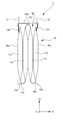
- FIG. 9 is an assembly diagram of an assembled battery in which batteries each containing an odd number (for example, five) of unit cells are connected in series.
- the assembled battery 80 includes a first battery 81, a second battery 82, and a third battery 83.
- the first battery 81 includes first to fifth unit cells 81a to 81e. Since the second to third batteries 82 to 83 have the same configuration as that of the first battery 81, detailed description thereof is omitted.
- the positive terminal 86a and the negative terminal 86b of the first battery 81 are formed on different surfaces.
- the first battery 81 and the second battery 82 can be electrically connected.
- the second battery 82 is extended by extending the negative terminal 86 d of the second battery 82 and the positive terminal 86 e of the third battery 83 along the outer surfaces of the second battery 82 and the third battery 83.
- the third battery 83 can be electrically connected.
- the number of batteries included in the assembled battery can be appropriately set according to the yield of materials, processing equipment, mounting space, and the like.
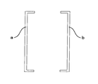
- the battery case 30 is configured by the case body including the first case side surface 30a, the second case side surface 30b, and the case bottom surface 30c, and the case top surface 30d, but the present invention is not limited thereto. It is not a thing. As shown in FIG. 10, it is good also as a battery case 30 by joining the edge part of bottomed cylindrical case a and case b mutually. In this case, the battery module 10 (100) accommodated in the battery case 30 is pressed by the inner surface of the case. Further, by sharing the shape of the case a and the case b, the cost of the battery can be reduced. Moreover, as shown in FIG.
- the battery case 30 by joining the edge part of the flat side wall c and the cased cylindrical case d mutually.
- the battery module 10 (100) accommodated in the battery case 30 is pressed by the inner surface of the case.
- components, such as a positive electrode terminal, can be concentrated on the upper wall part d1 of case d.
- the positive terminal connection tab 12b (negative terminal connection tab 12c) connected to the total positive terminal 21 (total negative terminal 22) may be bent. Thereby, since the so-called play can be made in the positive electrode terminal connection tab 12b (negative electrode terminal connection tab 12c), the load applied to the positive electrode terminal connection tab 12b (negative electrode terminal connection tab 12c) during vibration of the battery is reduced.
Abstract
[Problem] To inhibit positional displacement of a power generation unit in a casing, while inhibiting an increase in the size of the battery. [Solution] A battery is characterized by having: a power generation unit in which single cells are covered by an insulating sheathing material; and a casing which has a sealed structure and which accommodates the power generation unit, the internal pressure of said casing being higher than the external pressure thereof. The power generation unit may be a battery module in which a cell group having the single cells arranged therein is covered by the sheathing material. The battery module can be accommodated in the casing in a state of being folded in areas in which conductive members for connecting adjacent single cells are located. A coolant passage in through which coolant is passed can be provided along a surface of the casing, said surface being the closest to the conductive members.
Description
本発明は、ケース内に発電部を収容した電池の構造に関するものである。
The present invention relates to a battery structure in which a power generation unit is housed in a case.
ケース内に発電部を収容した電池が知られている。特許文献1は、シート状の発電部を軸周りに捲き回した扁平形状の捲回体の両端部をケース内において吊り持ち支持した電池を開示する。このように捲回体をケース内で吊り持ち支持することにより、捲回体はケース内の所定の位置に位置決めされる。
電池 A battery that houses a power generation unit in a case is known. Patent Document 1 discloses a battery in which both ends of a flat wound body in which a sheet-shaped power generation unit is wound around an axis are suspended and supported in a case. Thus, the winding body is positioned at a predetermined position in the case by suspending and supporting the winding body in the case.
しかしながら、上述の構成では、捲回体を吊り持ち支持するための支持部材が必要となるため、電池が大型化する。
However, the above-described configuration requires a support member for supporting the wound body in a suspended manner, so that the battery is increased in size.
そこで、本発明は、電池の大型化を抑制しながら、ケース内における発電部の位置ずれを抑制することを目的とする。
Therefore, an object of the present invention is to suppress the displacement of the power generation unit in the case while suppressing the increase in size of the battery.
上記課題を解決するために、本願発明に係る電池は、(1)単電池を絶縁性の外装材により覆った発電部と、前記発電部を収容する密閉構造のケースと、を有し、前記ケースは、内圧が外圧よりも高い。
In order to solve the above-described problems, a battery according to the present invention includes (1) a power generation unit in which a single cell is covered with an insulating exterior material, and a sealed structure case that houses the power generation unit, In the case, the internal pressure is higher than the external pressure.
(2)上記(1)の構成において、前記発電部は、前記単電池が並べられた電池群を前記外装材により覆った電池モジュールであり、前記電池モジュールは、隣接する前記単電池を接続する導電部材が位置する領域において折り曲げられた状態で前記ケースに収容することができる。(2)の構成によれば、電池の大型化を抑制しながら、ケース内における各単電池の位置ずれをより効果的に抑制することができる。
(2) In the configuration of (1), the power generation unit is a battery module in which a battery group in which the single cells are arranged is covered with the exterior material, and the battery module connects the adjacent single cells. It can be accommodated in the case in a folded state in the region where the conductive member is located. According to the configuration of (2), it is possible to more effectively suppress the positional deviation of each single cell in the case while suppressing the increase in size of the battery.
(3)上記(2)の構成において、前記導電部材に最も近い前記ケースの面に沿って冷媒を導通させる冷媒通路を設けることができる。(3)の構成によれば、充放電の際に電池モジュールの中でより温度の高くなりやすい部位に近接した領域が冷却されるため、電池冷却を効率的に行うことができる。
(3) In the configuration of the above (2), a refrigerant passage for conducting the refrigerant can be provided along the surface of the case closest to the conductive member. According to the structure of (3), since the area | region close | similar to the site | part which becomes easy to become high temperature in a battery module in the case of charging / discharging is cooled, battery cooling can be performed efficiently.
(4)上記(2)又は(3)の構成において、前記ケースは、第1の方向において互いに向き合う第1の側面と、前記第1の方向に直交する第2の方向において互いに向き合う第2の側面と、底面と、天面とを有し、前記電池モジュールの電力を前記ケースの外部に取り出すための一対の取り出し電極は、前記天面側に設けられており、前記電池群に含まれる前記単電池の個数は、偶数であり、前記電池群は、前記天面側の端部が第1の接続部材を介して前記一方の取り出し電極に接続され、前記底面側の端部が前記導電部材に接続される第1の単電池と、前記天面側の端部が第2の接続部材を介して前記他方の取り出し電極に接続され、前記底面側の端部が前記導電部材に接続される第2の単電池とを含んでいる。(4)の構成によれば、電池群を取り出し電極に接続するための接続部材の長さを小さくすることができる。これにより、コストを削減することができる。
(4) In the configuration of (2) or (3), the case includes a first side surface facing each other in a first direction and a second side facing each other in a second direction orthogonal to the first direction. A pair of extraction electrodes having a side surface, a bottom surface, and a top surface for extracting the power of the battery module to the outside of the case are provided on the top surface side, and are included in the battery group. The number of single cells is an even number, and in the battery group, the end on the top surface side is connected to the one extraction electrode via a first connection member, and the end on the bottom surface side is the conductive member. A first cell connected to the first surface, an end on the top surface side connected to the other extraction electrode via a second connection member, and an end on the bottom surface side connected to the conductive member A second unit cell. According to the structure of (4), the length of the connection member for taking out a battery group and connecting it to an electrode can be made small. Thereby, cost can be reduced.
(5)上記(4)の構成において、前記電池群は、さらに、前記導電部材を介して前記第1の単電池に接続される第3の単電池と、前記導電部材を介して前記第3の単電池に接続される第4の単電池と、を含み、前記第1の接続部材は、前記第1の単電池の正極及び負極のうち一方の電極に接続されており、前記導電部材は、前記外装材の外部に露出しており、前記第1の単電池における他方の電極に接続される第1の電圧検出部と、前記第3の単電池及び前記第4の単電池を接続する前記導電部材の露出部分に接続される第2の電圧検出部と、を有している。(5)の構成によれば、第1の単電池と第3の単電池とを接続する接続部材に電圧検出部が無くても、第1及び第3の単電池の各電圧を検出することができる。これにより、コストを削減することができる。
(5) In the configuration of (4), the battery group further includes a third unit cell connected to the first unit cell through the conductive member, and the third unit cell through the conductive member. A fourth unit cell connected to the unit cell, wherein the first connection member is connected to one of the positive electrode and the negative electrode of the first unit cell, and the conductive member is The first voltage detection unit exposed to the outside of the exterior material and connected to the other electrode of the first unit cell is connected to the third unit cell and the fourth unit cell. And a second voltage detector connected to the exposed portion of the conductive member. According to the structure of (5), even if there is no voltage detection part in the connection member which connects a 1st cell and a 3rd cell, each voltage of a 1st and 3rd cell is detected. Can do. Thereby, cost can be reduced.
(6)上記(5)の構成において、前記第1の電圧検出部は、前記第1の単電池における前記天面側の端部に接続することができる。
(6) In the configuration of (5), the first voltage detection unit can be connected to an end portion on the top surface side of the first unit cell.
(7)上記(4)~(6)のうちいずれか一つに記載の電池を複数有する組電池であって、各前記単電池の各前記一対の取り出し電極は、前記第1の方向に並んでいる。
(7) An assembled battery including a plurality of the batteries according to any one of (4) to (6), wherein each of the pair of extraction electrodes of each of the unit cells is arranged in the first direction. It is out.
(8)上記(1)~(6)のうちいずれか一つに記載の電池は、車両に搭載することができる。この場合、前記電池から供給される電力により、車両走行用のモータが駆動される。
(8) The battery described in any one of (1) to (6) above can be mounted on a vehicle. In this case, the motor for driving the vehicle is driven by the electric power supplied from the battery.
(9)上記(7)に記載の組電池は、車両に搭載することができる。この場合、前記組電池から供給される電力により、車両走行用のモータが駆動される。
を有する車両。 (9) The assembled battery according to (7) can be mounted on a vehicle. In this case, the motor for driving the vehicle is driven by the electric power supplied from the assembled battery.
Vehicle with.
を有する車両。 (9) The assembled battery according to (7) can be mounted on a vehicle. In this case, the motor for driving the vehicle is driven by the electric power supplied from the assembled battery.
Vehicle with.
本発明によれば、電池の大型化を抑制しながら、ケース内における発電要素の位置ずれを抑制することを目的とする。
An object of the present invention is to suppress the displacement of the power generation element in the case while suppressing the increase in size of the battery.
(第1実施形態)
図面を参照しながら、本発明の第1実施形態について説明する。図1は、電池モジュール(発電部に相当する)の展開図である。X軸、Y軸及びZ軸は互いに直交する三軸であり、X軸は電池モジュールの長手方向に直交する方向に対応しており、Y軸は電池モジュールの長手方向に対応しており、Z軸は電池モジュールの厚み方向に対応している。図2は、電池モジュールを図1のX-X´断面で切断した断面図である。図3は、電池モジュールが組み込まれた電池の外観斜視図である。T1軸、T2軸及びT3軸は互いに直交する三軸である。図4は、図3の電池をT-T´断面で切断した断面図である。 (First embodiment)
A first embodiment of the present invention will be described with reference to the drawings. FIG. 1 is a development view of a battery module (corresponding to a power generation unit). X axis, Y axis and Z axis are three axes orthogonal to each other, X axis corresponds to the direction orthogonal to the longitudinal direction of the battery module, Y axis corresponds to the longitudinal direction of the battery module, Z The axis corresponds to the thickness direction of the battery module. FIG. 2 is a cross-sectional view of the battery module taken along the line XX ′ of FIG. FIG. 3 is an external perspective view of a battery in which a battery module is incorporated. T1 axis, T2 axis and T3 axis are three axes orthogonal to each other. FIG. 4 is a cross-sectional view of the battery of FIG. 3 cut along the TT ′ cross section.
図1を参照して、電池モジュール10は、電池群11と、単電池間接続タブ(導電部材に相当する)12aと、正極端子接続タブ12b(第1の接続部材に相当する)と、負極端子接続タブ12c(第2に接続部材に相当する)と、外装材13とを含む。電池群11は、第1の単電池11a、第2の単電池11b、第3の単電池11c及び第4の単電池11dを含む。これらの第1~第4の単電池11a~11dは、外装材13の長手方向であるY軸方向に並んでいる。ただし、単電池11の個数は1~3、或いは5つ以上であってもよい。第1の単電池11aはY軸方向の一端部に位置し、第2の単電池11bはY軸方向の他端部に位置する。
Referring to FIG. 1, a battery module 10 includes a battery group 11, an inter-cell connection tab (corresponding to a conductive member) 12a, a positive terminal connecting tab 12b (corresponding to a first connecting member), a negative electrode A terminal connection tab 12c (secondly corresponding to a connection member) and an exterior material 13 are included. The battery group 11 includes a first cell 11a, a second cell 11b, a third cell 11c, and a fourth cell 11d. These first to fourth unit cells 11 a to 11 d are arranged in the Y-axis direction, which is the longitudinal direction of the exterior member 13. However, the number of unit cells 11 may be 1 to 3, or 5 or more. The first unit cell 11a is located at one end in the Y-axis direction, and the second unit cell 11b is located at the other end in the Y-axis direction.
外装材13は、フィルム部材13a、13bにより構成されている。これらのフィルム部材13a、13bは、第1~第4の単電池11a~11dを挟んでおり、この外縁側の領域において、互いに熱融着されている。フィルム部材13a、13bが互いに熱融着されることにより、外装材13の内部に第1~第4の単電池11a~11dが密閉される。なお、単電池間接続タブ12aは、外装材13の外部に露出していてもよい。
The exterior material 13 is composed of film members 13a and 13b. These film members 13a and 13b sandwich the first to fourth unit cells 11a to 11d and are heat-sealed to each other in the outer edge region. The first to fourth unit cells 11a to 11d are hermetically sealed in the exterior member 13 by heat-sealing the film members 13a and 13b. Note that the inter-cell connection tab 12 a may be exposed to the outside of the exterior material 13.
フィルム部材13a、13bには、絶縁性を有する可撓性のシートを用いることができる。フィルム部材13a、13bはラミネートフィルムであってもよい。このように、外装材13が絶縁性を有することにより、第1~第4の単電池11a~11dを一つの電池モジュールとしてユニット化することができる。
As the film members 13a and 13b, flexible sheets having insulating properties can be used. The film members 13a and 13b may be laminate films. As described above, since the exterior material 13 has an insulating property, the first to fourth unit cells 11a to 11d can be unitized as one battery module.
図2を参照して、第1の単電池11aは、正極体111a、負極体111b及びセパレータ111cを含み、正極体111a及び負極体111bはセパレータ111cを介して積層されている。なお、以下の説明において、正極体111a、負極体111b及びセパレータ111cが積層される方向を、積層方向という場合がある。第1~第4の単電池11a~11dは、ニッケル水素電池、リチウムイオン電池などの二次電池、或いはキャパシタであってもよい。なお、図2は、一部の正極体111a、負極体111b及びセパレータ111cを省略して図示する。
Referring to FIG. 2, the first unit cell 11a includes a positive electrode body 111a, a negative electrode body 111b, and a separator 111c, and the positive electrode body 111a and the negative electrode body 111b are stacked via the separator 111c. In the following description, the direction in which the positive electrode body 111a, the negative electrode body 111b, and the separator 111c are stacked may be referred to as a stacking direction. The first to fourth unit cells 11a to 11d may be secondary batteries such as nickel metal hydride batteries and lithium ion batteries, or capacitors. In FIG. 2, some of the positive electrode body 111a, the negative electrode body 111b, and the separator 111c are omitted.
正極体111aは、集電体と、集電体の表面に形成される正極層とを含む。正極層は、正極活物質、導電剤等を含む。正極活物質は、LiCoO2などのLi・Co系複合酸化物、LiNiO2などのLi・Ni系複合酸化物、スピネルLiMn2O4などのLi・Mn系複合酸化物、LiFeO2などのLi・Fe系複合酸化物であってもよい。正極活物質は、LiFePO4などの遷移金属とリチウムのリン酸化合物や硫酸化合物や、V2O5、MnO2、TiS2、MoS2、MoO3などの遷移金属酸化物や硫化物や、PbO2、AgO、NiOOHであってもよい。
The positive electrode body 111a includes a current collector and a positive electrode layer formed on the surface of the current collector. The positive electrode layer includes a positive electrode active material, a conductive agent, and the like. The positive electrode active material, Li · Co-based composite oxide such as LiCoO 2, Li · Ni-based composite oxide such as LiNiO 2, Li · Mn-based composite oxide such as spinel LiMn 2 O 4, Li · such LiFeO 2 Fe-based composite oxides may also be used. The positive electrode active material includes transition metal and lithium phosphate compounds and sulfuric acid compounds such as LiFePO 4 , transition metal oxides and sulfides such as V 2 O 5 , MnO 2 , TiS 2 , MoS 2 , and MoO 3 , PbO 2 , AgO, NiOOH.
負極体111bは、集電体と、集電体の表面に形成される負極層とを含む。負極層は、負極活物質、導電剤等を含む。負極活物質は、金属酸化物、リチウム-金属複合酸化物、カーボンであってもよい。
The negative electrode body 111b includes a current collector and a negative electrode layer formed on the surface of the current collector. The negative electrode layer includes a negative electrode active material, a conductive agent, and the like. The negative electrode active material may be a metal oxide, a lithium-metal composite oxide, or carbon.
正極端子接続タブ12bは、第1の単電池11aの積層方向の一端部に接続されている。正極端子接続タブ12bは、電池1の総プラス端子21(取り出し電極に相当する)に接続されている。正極端子接続タブ12b及び総プラス端子21の接続方法は、超音波溶接、スポット溶接であってもよい。
The positive electrode terminal connection tab 12b is connected to one end of the first unit cell 11a in the stacking direction. The positive electrode terminal connection tab 12 b is connected to the total positive terminal 21 (corresponding to the extraction electrode) of the battery 1. The method of connecting the positive terminal connecting tab 12b and the total plus terminal 21 may be ultrasonic welding or spot welding.
負極端子接続タブ12cは、第2の単電池11bの積層方向の一端部に接続されている。負極端子接続タブ12cは、電池1の総マイナス端子22(取り出し電極に相当する)に接続されている。負極端子接続タブ12c及び総マイナス端子22の接続方法は、超音波溶接、スポット溶接であってもよい。
The negative electrode terminal connection tab 12c is connected to one end of the second unit cell 11b in the stacking direction. The negative electrode terminal connection tab 12c is connected to the total negative terminal 22 (corresponding to the extraction electrode) of the battery 1. The method for connecting the negative terminal connecting tab 12c and the total minus terminal 22 may be ultrasonic welding or spot welding.
セパレータ111cは、電解質を含む。電解質は、固体電解質、或いは電解液であってもよい。固体電解質には、高分子固体電解質や無機固体電解質を用いることができる。高分子固体電解質には、例えば、ポリエチレンオキシド(PEO)、ポリプロピレンオキシド(PPO)、これらの共重合体を用いることができる。高分子固体電解質は、イオン伝導性を確保するためにリチウム塩を含んでいてもよい。リチウム塩には、例えば、LiBF4、LiPF6、LiN(SO2CF3)2、LiN(SO2C2F5)2、又はこれらの混合物を用いることができる。
Separator 111c contains an electrolyte. The electrolyte may be a solid electrolyte or an electrolytic solution. As the solid electrolyte, a polymer solid electrolyte or an inorganic solid electrolyte can be used. As the polymer solid electrolyte, for example, polyethylene oxide (PEO), polypropylene oxide (PPO), or a copolymer thereof can be used. The polymer solid electrolyte may contain a lithium salt in order to ensure ion conductivity. As the lithium salt, for example, LiBF 4 , LiPF 6 , LiN (SO 2 CF 3 ) 2 , LiN (SO 2 C 2 F 5 ) 2 , or a mixture thereof can be used.
図3及び図4を参照して、電池モジュール10は、電池ケース30の内部に収容されている。電池ケース30は、T3軸(第1の方向に相当する)方向において互いに向き合う一対の第1のケース側面30aと、T1軸(第2の方向に相当する)方向において互いに向き合う一対の第2のケース側面30bと、ケース底面30cと、ケース天面30dとを含む。なお、図3では、ケース天面30dが省略されている。
3 and 4, the battery module 10 is accommodated in the battery case 30. The battery case 30 has a pair of first case side surfaces 30a facing each other in the T3 axis (corresponding to the first direction) and a pair of second cases facing each other in the T1 axis (corresponding to the second direction). It includes a case side surface 30b, a case bottom surface 30c, and a case top surface 30d. In FIG. 3, the case top surface 30d is omitted.
ここで、第1のケース側面30a、第2のケース側面30b及びケース底面30cからなるケース本体と、ケース底面30dとは、それぞれ別体で製造することができる。ケース本体は、例えば、プレス成形により製造することができる。ケース天面30dは、第1のケース側面30a及び第2のケース側面30bの内面に溶接することにより、固定することができる。電池ケース30には、金属を用いることができる。
Here, the case main body composed of the first case side surface 30a, the second case side surface 30b, and the case bottom surface 30c, and the case bottom surface 30d can be manufactured separately. The case body can be manufactured, for example, by press molding. The case top surface 30d can be fixed by welding to the inner surfaces of the first case side surface 30a and the second case side surface 30b. A metal can be used for the battery case 30.
電池モジュール10は、曲げ部10aにおいて折り曲げられている。曲げ部10aは、隣接する単電池の中間部分、つまり、隣接する単電池を繋ぐ単電池間接続タブ12aが位置する領域に形成されている。
The battery module 10 is bent at the bent portion 10a. The bent portion 10a is formed in an intermediate portion between adjacent unit cells, that is, a region where the inter-unit cell connection tab 12a connecting the adjacent unit cells is located.
第1の単電池11aは、ケース天面30d側の端部が正極端子接続タブ12bを介して総プラス端子21に接続され、ケース底面30c側の端部が単電池間接続タブ12aを介して第3の単電池11cに接続されている。
In the first unit cell 11a, the end on the case top surface 30d side is connected to the total plus terminal 21 via the positive terminal connecting tab 12b, and the end on the case bottom surface 30c side is connected to the inter-cell connection tab 12a. It is connected to the third cell 11c.
第2の単電池11bは、ケース天面30d側の端部が負極端子接続タブ12cを介して総マイナス端子22に接続され、ケース底面30c側の端部が単電池間接続タブ12aを介して第4の単電池11dに接続されている。
In the second cell 11b, the end on the case top surface 30d side is connected to the total minus terminal 22 via the negative electrode terminal connection tab 12c, and the end on the case bottom surface 30c side is connected to the inter-cell connection tab 12a. It is connected to the fourth unit cell 11d.
このように、電池ケース30の内部に電池モジュール10を折り曲げた状態で収容することにより、電池ケース30の内部のスペースを有効に活用することができる。これにより、電池1の大型化が抑制される。
Thus, by accommodating the battery module 10 in a folded state inside the battery case 30, the space inside the battery case 30 can be used effectively. Thereby, the enlargement of the battery 1 is suppressed.
また、電池群11を構成する単電池の個数が偶数に設定され、さらに、電池ケース30の内部に電池モジュール10が折り曲げられた状態で収容されることにより、総プラス端子21と、正極端子接続部12bが接続される第1の単電池11aの接続部位との間隔を小さくすることができる。これにより、正極端子接続部12bの長さを小さくすることができる。同様に、総マイナス端子22と、負極端子接続部12cが接続される第2の単電池11bの接続部位との間隔を小さくすることができる。これにより、負極端子接続部12cの長さを小さくすることができる。
In addition, the number of single cells constituting the battery group 11 is set to an even number, and the battery module 10 is housed in a folded state inside the battery case 30 so that the total positive terminal 21 and the positive terminal are connected. The space | interval with the connection site | part of the 1st cell 11a to which the part 12b is connected can be made small. Thereby, the length of the positive electrode terminal connection part 12b can be made small. Similarly, the interval between the total negative terminal 22 and the connection portion of the second unit cell 11b to which the negative terminal connection portion 12c is connected can be reduced. Thereby, the length of the negative electrode terminal connection part 12c can be made small.
ケース底面30cには、冷却ダクト31が設けられている。冷却ダクト31は、冷却フィン31aと、ダクト壁部31bとを含む。冷却フィン31aは、ケース底面30cに接触しており、ケース底面30cの長手方向(T1軸方向)に所定間隔毎設けられている。冷却フィン31aには、熱伝導率の高い金属を用いることができる。金属は、アルミニウムであってもよい。
A cooling duct 31 is provided on the case bottom surface 30c. The cooling duct 31 includes cooling fins 31a and duct wall portions 31b. The cooling fins 31a are in contact with the case bottom surface 30c and are provided at predetermined intervals in the longitudinal direction (T1-axis direction) of the case bottom surface 30c. A metal having high thermal conductivity can be used for the cooling fin 31a. The metal may be aluminum.
図5は、冷却フィンを加工する加工装置の動作説明図であり、(a)~(e)の順番で加工が進むものとする。加工装置には、インパクト成形装置を用いることができる。インパクト加工装置は、パンチ81及びダイス82を含む。パンチ81は、ダイス82の凹部に対して進退する。パンチ81は、図示しないモータにより駆動される。ダイス82の凹部には、冷却フィンの母材となるスラグMが載置される。スラグMは、アルミニウムからなる円柱状のインゴットであってもよい。
FIG. 5 is a diagram for explaining the operation of the processing apparatus for processing the cooling fin, and it is assumed that the processing proceeds in the order of (a) to (e). An impact molding apparatus can be used as the processing apparatus. The impact processing apparatus includes a punch 81 and a die 82. The punch 81 advances and retreats with respect to the concave portion of the die 82. The punch 81 is driven by a motor (not shown). In the recess of the die 82, the slag M serving as a base material for the cooling fin is placed. The slag M may be a cylindrical ingot made of aluminum.
ダイス82の凹部に向けてパンチ81を下降させると、スラグMが押し潰され、押し潰れたスラグMの一部がパンチ81とダイス82との隙間から延出することにより、冷却フィン31aが形成される。この方法によれば、ダイス82に向けてパンチ81を下降させるだけで、簡単に冷却フィン31aを製造することができる。また、金型の費用が削減され、電池1の製造コストの増大を抑制できる。
When the punch 81 is lowered toward the concave portion of the die 82, the slag M is crushed, and a part of the slag M that is crushed extends from the gap between the punch 81 and the die 82, thereby forming the cooling fin 31a. Is done. According to this method, the cooling fin 31a can be easily manufactured simply by lowering the punch 81 toward the die 82. Moreover, the cost of the mold is reduced, and an increase in the manufacturing cost of the battery 1 can be suppressed.
ケース底面30c、冷却フィン31a及びダクト壁部31bに囲まれた空間によって、冷媒を導通させるための冷媒経路が形成される。この冷媒経路の内部を流れる冷媒によって、ケース底面30cが冷却され、さらに、電池モジュール10を冷却することができる。これにより、第1~第4の単電池11a~11dの劣化が抑制される。冷媒は、空気、又は液状の熱交換媒体であってもよい。
A refrigerant path for conducting the refrigerant is formed by the space surrounded by the case bottom surface 30c, the cooling fin 31a, and the duct wall portion 31b. The case bottom surface 30c is cooled by the refrigerant flowing in the refrigerant path, and the battery module 10 can be further cooled. As a result, the deterioration of the first to fourth unit cells 11a to 11d is suppressed. The refrigerant may be air or a liquid heat exchange medium.
ここで、曲げ部10aは、電池モジュール10を充放電させた際に、他の部位よりも温度が高くなる場合がある。つまり、曲げ部10aには単電池間接続タブ12aが位置するため、電池モジュール10を充放電させた際の発熱温度が相対的に高くなる。曲げ部10aは、ケース底面30cに接触しており、ケース底面30cには冷却フィン31aが接触しているため、冷却ダクト31の内部を流れる冷媒によって、第1~第4の単電池11a~11dを効率良く冷却することができる。
Here, when the battery module 10 is charged / discharged, the bent portion 10a may have a temperature higher than that of other portions. That is, since the inter-cell connection tab 12a is located in the bent portion 10a, the heat generation temperature when the battery module 10 is charged and discharged is relatively high. The bent portion 10a is in contact with the case bottom surface 30c, and since the cooling fins 31a are in contact with the case bottom surface 30c, the first to fourth unit cells 11a to 11d are cooled by the refrigerant flowing inside the cooling duct 31. Can be efficiently cooled.
電池ケース30の内圧は、外圧よりも高く設定されている。電池ケース30の内圧を高くする方法は、不活性ガス(例えば、窒素ガス)、或いは空気を電池ケース30の内部に供給する方法であってもよい。電池ケース30の内部に不活性ガスなどが送り込まれることにより、電池ケース30の内部は加圧雰囲気となり、電池モジュール10は電池ケース30の内面に押圧される。
The internal pressure of the battery case 30 is set higher than the external pressure. The method of increasing the internal pressure of the battery case 30 may be a method of supplying an inert gas (for example, nitrogen gas) or air into the battery case 30. By sending an inert gas or the like into the battery case 30, the inside of the battery case 30 becomes a pressurized atmosphere, and the battery module 10 is pressed against the inner surface of the battery case 30.
電池モジュール10が押圧されることにより、電池モジュール10の位置ずれが抑制される。電池モジュール10の位置ずれが抑制されることにより、電池モジュール10の外装材13が電池ケース30の内壁に摺動して、摩耗などすることを抑制できる。また、電池モジュール10が押圧されることにより、単電池の発電要素である正極体111a、負極体111b及びセパレータ111cがより強固に密着するため、電池モジュール10の入出力特性の低下を抑制できる。
When the battery module 10 is pressed, the displacement of the battery module 10 is suppressed. By suppressing the displacement of the battery module 10, it is possible to suppress the exterior material 13 of the battery module 10 from sliding on the inner wall of the battery case 30 and wearing. In addition, when the battery module 10 is pressed, the positive electrode body 111a, the negative electrode body 111b, and the separator 111c, which are power generation elements of the unit cell, are more firmly adhered to each other, so that a decrease in input / output characteristics of the battery module 10 can be suppressed.
ここで、電池ケース30の内部において電池モジュール10を拘束する方法として、電電池ケース30の外部に拘束部材を組み付け、この拘束部材により電池ケースを押圧する方法が知られている。しかしながら、この方法では、拘束部材を電池ケース30に組み付ける必要があるため、組み立て工程が煩雑化し、コストも増大する。本実施形態の電池1によれば、拘束部材が無くても、電池モジュール10を拘束することができる。これにより、組み立て作業の煩雑化を抑制しながら、コストの増大を抑制することができる。
Here, as a method of restraining the battery module 10 inside the battery case 30, a method is known in which a restraining member is assembled outside the battery case 30 and the battery case is pressed by the restraining member. However, in this method, since the restraint member needs to be assembled to the battery case 30, the assembly process becomes complicated and the cost increases. According to the battery 1 of the present embodiment, the battery module 10 can be restrained without a restraining member. Thereby, increase in cost can be suppressed, suppressing complication of assembly work.
電池ケース30の内圧によって電池モジュール10が拘束されることにより、電池ケース30の内部において電池モジュール10を吊り持ち支持するための支持部材を省略することができる。これにより、電池ケース30の内部において、電池モジュール10を配置するためのスペースが増大するため、電池1の大型化を抑制しながら、電池モジュール10のサイズを大きくすることもできる。
Since the battery module 10 is restrained by the internal pressure of the battery case 30, a support member for supporting the battery module 10 in a suspended manner inside the battery case 30 can be omitted. Thereby, since the space for arranging the battery module 10 in the battery case 30 increases, the size of the battery module 10 can be increased while suppressing an increase in the size of the battery 1.
ここで、過充電、過放電などの電池異常の際に、第1~第4の単電池11a~11dからガスが放出され、ガス外装材13の内圧が高まる場合がある。本実施形態では、電池ケース30の内部の圧力によりガス外装材13が外部から加圧されるため、ガスが外装材13から流出するのを抑制できる。
Here, when a battery abnormality such as overcharge or overdischarge occurs, gas may be released from the first to fourth unit cells 11a to 11d, and the internal pressure of the gas exterior member 13 may increase. In the present embodiment, since the gas exterior material 13 is pressurized from the outside by the pressure inside the battery case 30, it is possible to suppress the outflow of gas from the exterior material 13.
電池モジュール10の外装材13は絶縁性を有し、電池ケース30は電位を持たないため、電池ケース30の内面に絶縁処理を施す必要がない。これにより、コストを削減することができる。
Since the exterior material 13 of the battery module 10 is insulative and the battery case 30 has no potential, it is not necessary to insulate the inner surface of the battery case 30. Thereby, cost can be reduced.
ここで、単電池を密閉するのに用いられる材料として、アルムニウムを含むラミネートフィルムが広く知られている。このアルミニウムを含むラミネートフィルムは、止水性を有するため、単電池の内部に水分が侵入するのを抑制することができる。本実施形態では、電池ケース30が金属で構成されており、この金属により単電池の外部から内部に水分が侵入するのを抑制することができる。したがって、本実施形態における外装材13には、アルミニウムを含まないラミネートフィルムを使用することもできる。これにより、材料選択の自由度を高めることができる。
Here, a laminate film containing aluminium is widely known as a material used for sealing a unit cell. Since the laminate film containing aluminum has water-stopping properties, moisture can be prevented from entering the inside of the unit cell. In this embodiment, the battery case 30 is comprised with the metal, and it can suppress that a water | moisture content penetrate | invades into the inside from the exterior of a single cell with this metal. Therefore, a laminate film that does not contain aluminum can be used for the exterior material 13 in the present embodiment. Thereby, the freedom degree of material selection can be raised.
上述の電池1は、車両に搭載することができる。電池1は、車両走行用のモータに電力を供給する。モータは、電池1から供給される電力により回転動作し、車両を走行させる。車両は、電池1のみを車両走行用の動力源として有する電気自動車、電池1と他の要素(例えば、内燃機関、燃料電池)とを動力源として兼用するハイブリッド自動車であってもよい。ハイブリッド自動車には、電池1を車両外部の電源により充電可能なプラグインハイブリッド自動車が含まれる。また、図6に図示するように、電池1を複数個接続した組電池Aが車両に搭載されていてもよい。組電池Aは、車両走行用のモータに電力を供給することにより、車両を走行させる。
The battery 1 described above can be mounted on a vehicle. The battery 1 supplies electric power to a vehicle running motor. The motor rotates with the electric power supplied from the battery 1 to drive the vehicle. The vehicle may be an electric vehicle having only the battery 1 as a power source for driving the vehicle, or a hybrid vehicle having both the battery 1 and another element (for example, an internal combustion engine, a fuel cell) as a power source. The hybrid vehicle includes a plug-in hybrid vehicle that can charge the battery 1 by a power source outside the vehicle. Further, as illustrated in FIG. 6, an assembled battery A in which a plurality of batteries 1 are connected may be mounted on the vehicle. The assembled battery A causes the vehicle to travel by supplying electric power to a motor for traveling the vehicle.
(第2実施形態)
図面を参照しながら、第2実施形態に係る電池について詳細に説明する。図6は、電池モジュール(発電部に相当する)100の展開図である。図7は、図4に対応する電池の断面図である。電池モジュール100は、第1の単電池51、第2の単電池52、第3の単電池53及び第4の単電池54を含む。第1の単電池51は電池モジュール100の一端部に位置し、第2の単電池52は電池モジュール100の他端部に位置する。 (Second Embodiment)
The battery according to the second embodiment will be described in detail with reference to the drawings. FIG. 6 is a development view of the battery module (corresponding to the power generation unit) 100. FIG. 7 is a cross-sectional view of the battery corresponding to FIG. Thebattery module 100 includes a first unit cell 51, a second unit cell 52, a third unit cell 53, and a fourth unit cell 54. The first cell 51 is located at one end of the battery module 100, and the second cell 52 is located at the other end of the battery module 100.
図面を参照しながら、第2実施形態に係る電池について詳細に説明する。図6は、電池モジュール(発電部に相当する)100の展開図である。図7は、図4に対応する電池の断面図である。電池モジュール100は、第1の単電池51、第2の単電池52、第3の単電池53及び第4の単電池54を含む。第1の単電池51は電池モジュール100の一端部に位置し、第2の単電池52は電池モジュール100の他端部に位置する。 (Second Embodiment)
The battery according to the second embodiment will be described in detail with reference to the drawings. FIG. 6 is a development view of the battery module (corresponding to the power generation unit) 100. FIG. 7 is a cross-sectional view of the battery corresponding to FIG. The
第1の単電池51は、正極体51a及び負極体51bを、セパレータを介して積層することに構成されている。正極体51a及び負極体51bは、それぞれ第1実施形態の正極体111a及び負極体111bと同じ構成であるため、詳細な説明を省略する。また、第2~第4の単電池54は、第1の単電池51と同じ構成であるため、詳細な説明を省略する。
The first unit cell 51 is configured by laminating a positive electrode body 51a and a negative electrode body 51b with a separator interposed therebetween. Since the positive electrode body 51a and the negative electrode body 51b have the same configurations as the positive electrode body 111a and the negative electrode body 111b of the first embodiment, detailed description thereof will be omitted. Further, the second to fourth unit cells 54 have the same configuration as the first unit cell 51, and thus detailed description thereof is omitted.
第1の単電池51の正極体51aは、正極端子接続タブ43(第1の接続部材に相当する)を介して、電池の正極端子57(取り出し電極に相当する)に接続されている。第1の単電池51の負極体51bには、電圧検出タブ41a(第1の電圧検出部に相当する)が接続されている。第1の単電池51の負極体51b及び第3の単電池53の正極体53aは、単電池間接続タブ42a(導電部材に相当する)を介して電気的及び機械的に接続されている。第3の単電池53の負極体53b及び第4の単電池54の正極体54aは、単電池間接続タブ42b(導電部材に相当する)を介して電気的および機械的に接続されている。第4の単電池54の負極体54b及び第2の単電池52の正極体52aは、単電池間接続タブ42c(導電部材に相当する)を介して電気的及び機械的に接続されている。第2の単電池52の負極体52bは、負極端子接続タブ44(第2の接続部材に相当する)を介して、電池の負極端子58(取り出し電極)に接続されている。
The positive electrode body 51a of the first cell 51 is connected to the positive electrode terminal 57 (corresponding to the take-out electrode) of the battery via the positive terminal connecting tab 43 (corresponding to the first connecting member). A voltage detection tab 41a (corresponding to a first voltage detection unit) is connected to the negative electrode body 51b of the first cell 51. The negative electrode body 51b of the first unit cell 51 and the positive electrode body 53a of the third unit cell 53 are electrically and mechanically connected via an inter-cell connection tab 42a (corresponding to a conductive member). The negative electrode body 53b of the third single battery 53 and the positive electrode body 54a of the fourth single battery 54 are electrically and mechanically connected via an inter-cell connection tab 42b (corresponding to a conductive member). The negative electrode body 54b of the fourth unit cell 54 and the positive electrode body 52a of the second unit cell 52 are electrically and mechanically connected via an inter-cell connection tab 42c (corresponding to a conductive member). The negative electrode body 52b of the second unit cell 52 is connected to the negative electrode terminal 58 (extraction electrode) of the battery via a negative electrode terminal connection tab 44 (corresponding to a second connection member).
図7に図示するように、電池モジュール100は、第1実施形態の電池モジュール10と同様に、隣接する単電池の境界部分で折り曲げられた状態で、電池ケース59の内部に収容されている。第3の単電池53と第4の単電池54とを接続する単電池間接続タブ42bは、外装材13の外部に露出しており、この露出部分に対して電圧検出端子56(第2の電圧検出部に相当する)が接触している。単電池間接続タブ42bは、弾性を有する。単電池間接続タブ42bは、その弾性力により電圧検出端子56に押し付けられている。ただし、単電池間接続タブ42b及び電圧検出端子56は、互いに溶接されることによって接合されていてもよい。
As shown in FIG. 7, the battery module 100 is housed in the battery case 59 in a state where the battery module 100 is bent at a boundary portion between adjacent unit cells, similarly to the battery module 10 of the first embodiment. The inter-cell connection tab 42b that connects the third unit cell 53 and the fourth unit cell 54 is exposed to the outside of the exterior member 13, and the voltage detection terminal 56 (second unit) is exposed to the exposed portion. (Corresponding to the voltage detector) is in contact. The inter-cell connection tab 42b has elasticity. The inter-cell connection tab 42b is pressed against the voltage detection terminal 56 by its elastic force. However, the unit cell connection tab 42b and the voltage detection terminal 56 may be joined together by welding.
ここで、正極端子接続タブ43、電圧検出タブ41a、電圧検出端子56、負極端子接続タブ44及び電圧検出タブ41bは、図示しない監視ユニットに対して、電気的に接続される。監視ユニットは、これらの正極端子接続タブ43、電圧検出タブ41a、電圧検出端子56、負極端子接続タブ44及び電圧検出タブ41bから取得した電圧情報を図示しないECU(electric control unit)に送信する。ECUは、正極端子接続タブ43及び電圧検出タブ41aを介して取得された電圧情報に基づき、第1の単電池51の電圧を算出する。ECUは、電圧検出タブ41a及び電圧検出端子56を介して取得された電圧情報に基づき、第3の単電池53の電圧を算出する。ECUは、電圧検出端子56及び電圧検出タブ41bを介して取得された電圧情報に基づき、第4の単電池54の電圧を算出する。ECUは、負極端子接続タブ44及び電圧検出タブ41bを介して取得された電圧情報に基づき、第2の単電池52の電圧を算出する。
Here, the positive terminal connection tab 43, the voltage detection tab 41a, the voltage detection terminal 56, the negative terminal connection tab 44, and the voltage detection tab 41b are electrically connected to a monitoring unit (not shown). The monitoring unit transmits the voltage information acquired from the positive terminal connection tab 43, the voltage detection tab 41a, the voltage detection terminal 56, the negative terminal connection tab 44, and the voltage detection tab 41b to an ECU (electric control unit) (not shown). The ECU calculates the voltage of the first cell 51 based on the voltage information acquired via the positive terminal connection tab 43 and the voltage detection tab 41a. The ECU calculates the voltage of the third unit cell 53 based on the voltage information acquired via the voltage detection tab 41 a and the voltage detection terminal 56. The ECU calculates the voltage of the fourth unit cell 54 based on the voltage information acquired through the voltage detection terminal 56 and the voltage detection tab 41b. The ECU calculates the voltage of the second unit cell 52 based on the voltage information acquired via the negative electrode terminal connection tab 44 and the voltage detection tab 41b.
上述の構成によれば、全ての単電池間に電圧検出タブが無くても、各単電池51~54の電圧を検出することができる。これにより、電池のコストが削減される。
According to the above-described configuration, the voltage of each of the unit cells 51 to 54 can be detected without a voltage detection tab between all the unit cells. This reduces the cost of the battery.
図7に図示するように、単電池の個数が偶数個である場合、正極端子接続タブ43、電圧検出タブ41a、電圧検出端子56、負極端子接続タブ44及び電圧検出タブ41bを電池ケース59の一端側に集めることができる。これにより、電圧検出経路をバスバーモジュールに一体化することができる。ここで、バスバーモジュールとは、複数の電池を含む組電池において、隣接する電池を接続する複数のバスバーをユニット化するものである。バスバーモジュールが用いられることにより、バスバーの組み付け作業が容易化等される。
As shown in FIG. 7, when the number of cells is an even number, the positive electrode terminal connection tab 43, the voltage detection tab 41 a, the voltage detection terminal 56, the negative electrode terminal connection tab 44, and the voltage detection tab 41 b are connected to the battery case 59. Can be collected at one end. Thereby, the voltage detection path can be integrated with the bus bar module. Here, the bus bar module is a battery pack including a plurality of batteries, in which a plurality of bus bars connecting adjacent batteries are unitized. By using the bus bar module, the assembly work of the bus bar is facilitated.
(変形例1)
上述の実施形態では、正極体111a、負極体111b及びセパレータ111cを所定方向に積層することにより単電池を構成したが、本発明はこれに限るものではなく、例えば、セパレータ111cを介して正極体111a及び負極体111b積層した積層シートを所定の軸周りに捲き回した捲回体により単電池を構成してもよい。 (Modification 1)
In the above-described embodiment, the unit cell is configured by laminating thepositive electrode body 111a, the negative electrode body 111b, and the separator 111c in a predetermined direction. However, the present invention is not limited to this, for example, the positive electrode body via the separator 111c. The unit cell may be constituted by a wound body obtained by rolling a laminated sheet in which 111a and the negative electrode body 111b are laminated around a predetermined axis.
上述の実施形態では、正極体111a、負極体111b及びセパレータ111cを所定方向に積層することにより単電池を構成したが、本発明はこれに限るものではなく、例えば、セパレータ111cを介して正極体111a及び負極体111b積層した積層シートを所定の軸周りに捲き回した捲回体により単電池を構成してもよい。 (Modification 1)
In the above-described embodiment, the unit cell is configured by laminating the
(変形例2)
上述の実施形態では、冷却ダクト31を電池ケース30のケース底面30cに沿って配置したが、本発明はこれに限るものではなく、他の部位に設けることができる。他の部位は、電池ケース30のケース側面30bであってもよい。また、別の変形例として、冷却ダクト31は、省略することもできる。 (Modification 2)
In the above-described embodiment, the coolingduct 31 is arranged along the case bottom surface 30c of the battery case 30, but the present invention is not limited to this, and can be provided in other parts. The other part may be the case side face 30b of the battery case 30. As another modification, the cooling duct 31 can be omitted.
上述の実施形態では、冷却ダクト31を電池ケース30のケース底面30cに沿って配置したが、本発明はこれに限るものではなく、他の部位に設けることができる。他の部位は、電池ケース30のケース側面30bであってもよい。また、別の変形例として、冷却ダクト31は、省略することもできる。 (Modification 2)
In the above-described embodiment, the cooling
(変形例3)
上述の実施形態では、電池に含まれる単電池の個数を偶数としたが、本発明は、これに限るものではなく、奇数であってもよい。図9は、単電池を奇数個(例えば、5個)収容した電池を直列に接続した組電池の組み立て図である。組電池80は、第1の電池81、第2の電池82及び第3の電池83を含む。第1の電池81は、第1~第5の単電池81a~81eを含む。第2~第3の電池82~83は、第1の電池81と同じ構成であるため、詳細な説明を省略する。 (Modification 3)
In the above-described embodiment, the number of single cells included in the battery is an even number. However, the present invention is not limited to this and may be an odd number. FIG. 9 is an assembly diagram of an assembled battery in which batteries each containing an odd number (for example, five) of unit cells are connected in series. The assembledbattery 80 includes a first battery 81, a second battery 82, and a third battery 83. The first battery 81 includes first to fifth unit cells 81a to 81e. Since the second to third batteries 82 to 83 have the same configuration as that of the first battery 81, detailed description thereof is omitted.
上述の実施形態では、電池に含まれる単電池の個数を偶数としたが、本発明は、これに限るものではなく、奇数であってもよい。図9は、単電池を奇数個(例えば、5個)収容した電池を直列に接続した組電池の組み立て図である。組電池80は、第1の電池81、第2の電池82及び第3の電池83を含む。第1の電池81は、第1~第5の単電池81a~81eを含む。第2~第3の電池82~83は、第1の電池81と同じ構成であるため、詳細な説明を省略する。 (Modification 3)
In the above-described embodiment, the number of single cells included in the battery is an even number. However, the present invention is not limited to this and may be an odd number. FIG. 9 is an assembly diagram of an assembled battery in which batteries each containing an odd number (for example, five) of unit cells are connected in series. The assembled
第1の電池81の正極端子86a及び負極端子86bは、異なる面に形成されている。この場合、図示するように、第1の電池81の負極端子86b及び第2の電池82の正極端子86cを第1の電池81及び第2の電池82の外面に沿って延在させることにより、第1の電池81及び第2の電池82を電気的に接続することができる。同様に、第2の電池82の負極端子86d及び第3の電池83の正極端子86eを第2の電池82及び第3の電池83の外面に沿って延在させることにより、第2の電池82及び第3の電池83を電気的に接続することができる。組電池に含まれる電池の個数は、材料の歩留まり、加工設備、搭載スペースなどに応じて適宜設定することができる。
The positive terminal 86a and the negative terminal 86b of the first battery 81 are formed on different surfaces. In this case, as illustrated, by extending the negative terminal 86b of the first battery 81 and the positive terminal 86c of the second battery 82 along the outer surfaces of the first battery 81 and the second battery 82, The first battery 81 and the second battery 82 can be electrically connected. Similarly, the second battery 82 is extended by extending the negative terminal 86 d of the second battery 82 and the positive terminal 86 e of the third battery 83 along the outer surfaces of the second battery 82 and the third battery 83. The third battery 83 can be electrically connected. The number of batteries included in the assembled battery can be appropriately set according to the yield of materials, processing equipment, mounting space, and the like.
(変形例4)
上述の実施形態では、電池ケース30を、第1のケース側面30a、第2のケース側面30b及びケース底面30cからなるケース本体と、ケース天面30dとから構成したが、本発明はこれに限るものではない。図10に示すように、有底筒状のケースa及びケースbの端部を互いに接合することにより電池ケース30としてもよい。この場合、電池ケース30の内部に収容される電池モジュール10(100)は、ケースの内面により押圧される。また、ケースa及びケースbの形状を共通化することにより、電池のコストを削減することができる。また、図11に示すように、平板状の側壁c及び有停筒状のケースdの端部を互いに接合することにより電池ケース30としてもよい。この場合、電池ケース30の内部に収容される電池モジュール10(100)は、ケースの内面により押圧される。また、ケースdの上壁部d1に正極端子等の部品を集中させることができる。 (Modification 4)
In the above-described embodiment, thebattery case 30 is configured by the case body including the first case side surface 30a, the second case side surface 30b, and the case bottom surface 30c, and the case top surface 30d, but the present invention is not limited thereto. It is not a thing. As shown in FIG. 10, it is good also as a battery case 30 by joining the edge part of bottomed cylindrical case a and case b mutually. In this case, the battery module 10 (100) accommodated in the battery case 30 is pressed by the inner surface of the case. Further, by sharing the shape of the case a and the case b, the cost of the battery can be reduced. Moreover, as shown in FIG. 11, it is good also as the battery case 30 by joining the edge part of the flat side wall c and the cased cylindrical case d mutually. In this case, the battery module 10 (100) accommodated in the battery case 30 is pressed by the inner surface of the case. Moreover, components, such as a positive electrode terminal, can be concentrated on the upper wall part d1 of case d.
上述の実施形態では、電池ケース30を、第1のケース側面30a、第2のケース側面30b及びケース底面30cからなるケース本体と、ケース天面30dとから構成したが、本発明はこれに限るものではない。図10に示すように、有底筒状のケースa及びケースbの端部を互いに接合することにより電池ケース30としてもよい。この場合、電池ケース30の内部に収容される電池モジュール10(100)は、ケースの内面により押圧される。また、ケースa及びケースbの形状を共通化することにより、電池のコストを削減することができる。また、図11に示すように、平板状の側壁c及び有停筒状のケースdの端部を互いに接合することにより電池ケース30としてもよい。この場合、電池ケース30の内部に収容される電池モジュール10(100)は、ケースの内面により押圧される。また、ケースdの上壁部d1に正極端子等の部品を集中させることができる。 (Modification 4)
In the above-described embodiment, the
(変形例5)
総プラス端子21(総マイナス端子22)に接続される正極端子接続タブ12b(負極端子接続タブ12c)は、撓んでいてもよい。これにより、正極端子接続タブ12b(負極端子接続タブ12c)において、いわゆる遊びができるため、電池の振動時に正極端子接続タブ12b(負極端子接続タブ12c)に加わる負荷が軽減される。 (Modification 5)
The positiveterminal connection tab 12b (negative terminal connection tab 12c) connected to the total positive terminal 21 (total negative terminal 22) may be bent. Thereby, since the so-called play can be made in the positive electrode terminal connection tab 12b (negative electrode terminal connection tab 12c), the load applied to the positive electrode terminal connection tab 12b (negative electrode terminal connection tab 12c) during vibration of the battery is reduced.
総プラス端子21(総マイナス端子22)に接続される正極端子接続タブ12b(負極端子接続タブ12c)は、撓んでいてもよい。これにより、正極端子接続タブ12b(負極端子接続タブ12c)において、いわゆる遊びができるため、電池の振動時に正極端子接続タブ12b(負極端子接続タブ12c)に加わる負荷が軽減される。 (Modification 5)
The positive
1 電池 10 電池モジュール 11 電池群
11a~11d 第1~第4の単電池 12a 単電池間接続タブ
12b 正極端子接続タブ 12c 負極端子接続タブ
30 電池ケース 31 冷却ダクト DESCRIPTION OFSYMBOLS 1 Battery 10 Battery module 11 Battery group 11a-11d 1st-4th cell 12a Inter-cell connection tab 12b Positive electrode terminal connection tab 12c Negative electrode terminal connection tab 30 Battery case 31 Cooling duct
11a~11d 第1~第4の単電池 12a 単電池間接続タブ
12b 正極端子接続タブ 12c 負極端子接続タブ
30 電池ケース 31 冷却ダクト DESCRIPTION OF
Claims (9)
- 単電池を絶縁性の外装材により覆った発電部と、
前記発電部を収容する密閉構造のケースと、を有し、
前記ケースは、内圧が外圧よりも高いことを特徴とする電池。 A power generation unit in which a single cell is covered with an insulating exterior material;
A case with a sealed structure that houses the power generation unit,
The battery is characterized in that the case has an internal pressure higher than an external pressure. - 前記発電部は、前記単電池が並べられた電池群を前記外装材により覆った電池モジュールであり、
前記電池モジュールは、隣接する前記単電池を接続する導電部材が位置する領域において折り曲げられた状態で前記ケースに収容されていることを特徴とする請求項1に記載の電池。 The power generation unit is a battery module in which a battery group in which the single cells are arranged is covered with the exterior material,
2. The battery according to claim 1, wherein the battery module is housed in the case in a state where the battery module is bent in a region where a conductive member connecting the adjacent unit cells is located. - 前記導電部材に最も近い前記ケースの面に沿って冷媒を導通させる冷媒通路を有することを特徴とする請求項2に記載の電池。 The battery according to claim 2, further comprising a refrigerant passage that conducts the refrigerant along the surface of the case closest to the conductive member.
- 前記ケースは、第1の方向において互いに向き合う第1の側面と、前記第1の方向に直交する第2の方向において互いに向き合う第2の側面と、底面と、天面とを有し、
前記電池モジュールの電力を前記ケースの外部に取り出すための一対の取り出し電極は、前記天面側に設けられており、
前記電池群に含まれる前記単電池の個数は、偶数であり、
前記電池群は、前記天面側の端部が第1の接続部材を介して前記一方の取り出し電極に接続され、前記底面側の端部が前記導電部材に接続される第1の単電池と、前記天面側の端部が第2の接続部材を介して前記他方の取り出し電極に接続され、前記底面側の端部が前記導電部材に接続される第2の単電池とを含むことを特徴とする請求項2又は3に記載の電池。 The case includes a first side surface facing each other in a first direction, a second side surface facing each other in a second direction orthogonal to the first direction, a bottom surface, and a top surface.
A pair of extraction electrodes for extracting the power of the battery module to the outside of the case is provided on the top surface side,
The number of unit cells included in the battery group is an even number,
The battery group includes a first unit cell in which an end portion on the top surface side is connected to the one extraction electrode via a first connection member, and an end portion on the bottom surface side is connected to the conductive member; And a second unit cell in which an end on the top surface side is connected to the other extraction electrode via a second connection member, and an end on the bottom surface side is connected to the conductive member. The battery according to claim 2 or 3, characterized in that: - 前記電池群は、さらに、前記導電部材を介して前記第1の単電池に接続される第3の単電池と、前記導電部材を介して前記第3の単電池に接続される第4の単電池と、を含み、
前記第1の接続部材は、前記第1の単電池の正極及び負極のうち一方の電極に接続されており、
前記導電部材は、前記外装材の外部に露出しており、
前記第1の単電池における他方の電極に接続される第1の電圧検出部と、
前記第3の単電池及び前記第4の単電池を接続する前記導電部材の露出部分に接続される第2の電圧検出部と、を有することを特徴とする請求項4に記載の電池。 The battery group further includes a third unit cell connected to the first unit cell via the conductive member, and a fourth unit connected to the third unit cell via the conductive member. A battery, and
The first connection member is connected to one of the positive electrode and the negative electrode of the first unit cell,
The conductive member is exposed to the outside of the exterior material,
A first voltage detector connected to the other electrode of the first unit cell;
The battery according to claim 4, further comprising: a second voltage detection unit connected to an exposed portion of the conductive member that connects the third unit cell and the fourth unit cell. - 前記第1の電圧検出部は、前記第1の単電池における前記天面側の端部に接続されていることを特徴とする請求項5に記載の電池。 The battery according to claim 5, wherein the first voltage detection unit is connected to an end of the first cell on the top surface side.
- 請求項4乃至6のうちいずれか一つに記載の電池を複数有する組電池であって、
各前記単電池の各前記一対の取り出し電極は、前記第1の方向に並んでいることを特徴とする組電池。 An assembled battery comprising a plurality of the batteries according to any one of claims 4 to 6,
Each of the pair of extraction electrodes of each unit cell is arranged in the first direction. - 請求項1乃至6のうちいずれか一つに記載の電池と、
前記電池から供給される電力を用いて回転することにより、車両を走行させるためのエネルギーを発生するモータと、
を有する車両。 A battery according to any one of claims 1 to 6,
A motor that generates energy for running the vehicle by rotating using electric power supplied from the battery;
Vehicle with. - 請求項7に記載の組電池と、
前記組電池から供給される電力を用いて回転することにより、車両を走行させるためのエネルギーを発生するモータと、
を有する車両。
An assembled battery according to claim 7;
A motor that generates energy for running the vehicle by rotating using electric power supplied from the assembled battery;
Vehicle with.
Priority Applications (3)
| Application Number | Priority Date | Filing Date | Title |
|---|---|---|---|
| US14/391,520 US20150064521A1 (en) | 2012-04-13 | 2012-12-10 | Battery, assembled battery, and vehicle |
| CN201280072331.5A CN104321902B (en) | 2012-04-13 | 2012-12-10 | battery, battery pack and vehicle |
| EP12874003.2A EP2838134A4 (en) | 2012-04-13 | 2012-12-10 | Battery, battery pack, and vehicle |
Applications Claiming Priority (2)
| Application Number | Priority Date | Filing Date | Title |
|---|---|---|---|
| JP2012-092452 | 2012-04-13 | ||
| JP2012092452A JP5591280B2 (en) | 2012-04-13 | 2012-04-13 | Battery, battery pack |
Publications (1)
| Publication Number | Publication Date |
|---|---|
| WO2013153588A1 true WO2013153588A1 (en) | 2013-10-17 |
Family
ID=49327200
Family Applications (1)
| Application Number | Title | Priority Date | Filing Date |
|---|---|---|---|
| PCT/JP2012/007880 WO2013153588A1 (en) | 2012-04-13 | 2012-12-10 | Battery, battery pack, and vehicle |
Country Status (5)
| Country | Link |
|---|---|
| US (1) | US20150064521A1 (en) |
| EP (2) | EP2838134A4 (en) |
| JP (1) | JP5591280B2 (en) |
| CN (1) | CN104321902B (en) |
| WO (1) | WO2013153588A1 (en) |
Cited By (2)
| Publication number | Priority date | Publication date | Assignee | Title |
|---|---|---|---|---|
| WO2016132119A1 (en) * | 2015-02-18 | 2016-08-25 | Bae Systems Plc | Electric battery assembly |
| CN112467188A (en) * | 2020-11-30 | 2021-03-09 | 远景动力技术(江苏)有限公司 | Assembling method of battery module |
Families Citing this family (25)
| Publication number | Priority date | Publication date | Assignee | Title |
|---|---|---|---|---|
| KR101829093B1 (en) * | 2014-10-22 | 2018-03-29 | 주식회사 엘지화학 | Cooling air flow control system and method for battery system |
| KR101776282B1 (en) * | 2014-10-31 | 2017-09-07 | 주식회사 엘지화학 | Battery module and producing method thereof |
| CN104466300A (en) * | 2014-12-08 | 2015-03-25 | 江苏港星方能超声洗净科技有限公司 | Battery cooling device |
| EP3107132A1 (en) * | 2015-06-17 | 2016-12-21 | BAE Systems PLC | Electric battery assembly |
| KR102415749B1 (en) * | 2015-08-05 | 2022-07-01 | 삼성에스디아이 주식회사 | Flexible battery |
| US11383213B2 (en) | 2016-03-15 | 2022-07-12 | Honda Motor Co., Ltd. | System and method of producing a composite product |
| US11171324B2 (en) | 2016-03-15 | 2021-11-09 | Honda Motor Co., Ltd. | System and method of producing a composite product |
| KR102063938B1 (en) * | 2016-08-12 | 2020-01-08 | 주식회사 엘지화학 | Secondary battery module having strap type frame and frame assembly for the same |
| KR102065098B1 (en) * | 2016-08-12 | 2020-01-10 | 주식회사 엘지화학 | Secondary battery module improved in frame structure and frame assembly for the same |
| DE102016118752A1 (en) | 2016-10-04 | 2018-04-05 | Johnson Controls Advanced Power Solutions Gmbh | ENERGY STORAGE MODULE AND METHOD FOR PRODUCING THEREOF |
| US11081684B2 (en) | 2017-05-24 | 2021-08-03 | Honda Motor Co., Ltd. | Production of carbon nanotube modified battery electrode powders via single step dispersion |
| US10658651B2 (en) | 2017-07-31 | 2020-05-19 | Honda Motor Co., Ltd. | Self standing electrodes and methods for making thereof |
| US20190036102A1 (en) | 2017-07-31 | 2019-01-31 | Honda Motor Co., Ltd. | Continuous production of binder and collector-less self-standing electrodes for li-ion batteries by using carbon nanotubes as an additive |
| US11121358B2 (en) | 2017-09-15 | 2021-09-14 | Honda Motor Co., Ltd. | Method for embedding a battery tab attachment in a self-standing electrode without current collector or binder |
| US11201318B2 (en) | 2017-09-15 | 2021-12-14 | Honda Motor Co., Ltd. | Method for battery tab attachment to a self-standing electrode |
| JP7028685B2 (en) * | 2018-03-22 | 2022-03-02 | 本田技研工業株式会社 | Battery structure |
| US20210020880A1 (en) * | 2018-03-28 | 2021-01-21 | Honda Motor Co., Ltd. | Solid-state battery module |
| GB2574023A (en) * | 2018-05-23 | 2019-11-27 | Robert Murray Smith | Method of construction of an elongated bipolar plate battery |
| US10873067B2 (en) | 2018-08-22 | 2020-12-22 | Microsoft Technology Licensing, Llc | Folding tab for ultra-thin battery cell connection |
| JP7161672B2 (en) | 2018-11-12 | 2022-10-27 | トヨタ自動車株式会社 | assembled battery |
| JP7161673B2 (en) | 2018-11-12 | 2022-10-27 | トヨタ自動車株式会社 | assembled battery |
| US11535517B2 (en) | 2019-01-24 | 2022-12-27 | Honda Motor Co., Ltd. | Method of making self-standing electrodes supported by carbon nanostructured filaments |
| US11325833B2 (en) | 2019-03-04 | 2022-05-10 | Honda Motor Co., Ltd. | Composite yarn and method of making a carbon nanotube composite yarn |
| US11352258B2 (en) | 2019-03-04 | 2022-06-07 | Honda Motor Co., Ltd. | Multifunctional conductive wire and method of making |
| US11539042B2 (en) | 2019-07-19 | 2022-12-27 | Honda Motor Co., Ltd. | Flexible packaging with embedded electrode and method of making |
Citations (11)
| Publication number | Priority date | Publication date | Assignee | Title |
|---|---|---|---|---|
| JPH0613064A (en) * | 1992-06-26 | 1994-01-21 | Shin Kobe Electric Mach Co Ltd | Film pack type sealed lead-acid battery unit |
| JPH10214638A (en) * | 1997-01-30 | 1998-08-11 | Hitachi Ltd | Lithium secondary battery |
| JP2006079909A (en) * | 2004-09-08 | 2006-03-23 | Toyota Motor Corp | Power storage module and manufacturing method of the same |
| JP2006185733A (en) * | 2004-12-27 | 2006-07-13 | Nissan Motor Co Ltd | Manufacturing method of battery pack and battery pack manufactured by this method |
| JP2006260975A (en) * | 2005-03-17 | 2006-09-28 | Dainippon Printing Co Ltd | Battery module |
| JP2009529216A (en) * | 2006-03-06 | 2009-08-13 | エルジー・ケム・リミテッド | Medium or large battery module |
| JP2011071109A (en) | 2009-08-27 | 2011-04-07 | Toshiba Corp | Battery |
| JP2011222230A (en) | 2010-04-07 | 2011-11-04 | Nissan Motor Co Ltd | Battery module |
| JP2011249250A (en) | 2010-05-29 | 2011-12-08 | Sanyo Electric Co Ltd | Battery pack |
| JP2012221580A (en) * | 2011-04-04 | 2012-11-12 | Toyota Motor Corp | Solid-state battery |
| WO2013008321A1 (en) * | 2011-07-13 | 2013-01-17 | トヨタ自動車株式会社 | Battery module |
Family Cites Families (10)
| Publication number | Priority date | Publication date | Assignee | Title |
|---|---|---|---|---|
| US2410952A (en) * | 1942-12-28 | 1946-11-12 | Electric Storage Battery Co | Heat transfer construction for electrolytic cells |
| US6087036A (en) * | 1997-07-25 | 2000-07-11 | 3M Innovative Properties Company | Thermal management system and method for a solid-state energy storing device |
| JP2004087238A (en) * | 2002-08-26 | 2004-03-18 | Nissan Motor Co Ltd | Layer built cell |
| US8420254B2 (en) * | 2007-12-25 | 2013-04-16 | Byd Co. Ltd. | End cover assembly for an electrochemical cell |
| US8231996B2 (en) * | 2008-02-15 | 2012-07-31 | Atieva Usa, Inc | Method of cooling a battery pack using flat heat pipes |
| DE102008034869A1 (en) * | 2008-07-26 | 2009-06-18 | Daimler Ag | Battery for use in motor vehicle with hybrid drive, has heat conducting elements including heat transfer surfaces such that inner temperatures of battery cells are approximately same under operating conditions provided for battery |
| DE102008061277A1 (en) * | 2008-12-10 | 2010-06-24 | Conti Temic Microelectronic Gmbh | energy storage |
| DE102009040814A1 (en) * | 2009-09-10 | 2011-03-17 | Behr Gmbh & Co. Kg | Method for producing an energy storage holder for a vehicle |
| US9343716B2 (en) * | 2011-12-29 | 2016-05-17 | Apple Inc. | Flexible battery pack |
| US8986872B2 (en) * | 2012-02-15 | 2015-03-24 | GM Global Technology Operations LLC | Battery design |
-
2012
- 2012-04-13 JP JP2012092452A patent/JP5591280B2/en active Active
- 2012-12-10 WO PCT/JP2012/007880 patent/WO2013153588A1/en active Application Filing
- 2012-12-10 EP EP12874003.2A patent/EP2838134A4/en not_active Withdrawn
- 2012-12-10 EP EP16156549.4A patent/EP3041065B1/en active Active
- 2012-12-10 CN CN201280072331.5A patent/CN104321902B/en active Active
- 2012-12-10 US US14/391,520 patent/US20150064521A1/en not_active Abandoned
Patent Citations (11)
| Publication number | Priority date | Publication date | Assignee | Title |
|---|---|---|---|---|
| JPH0613064A (en) * | 1992-06-26 | 1994-01-21 | Shin Kobe Electric Mach Co Ltd | Film pack type sealed lead-acid battery unit |
| JPH10214638A (en) * | 1997-01-30 | 1998-08-11 | Hitachi Ltd | Lithium secondary battery |
| JP2006079909A (en) * | 2004-09-08 | 2006-03-23 | Toyota Motor Corp | Power storage module and manufacturing method of the same |
| JP2006185733A (en) * | 2004-12-27 | 2006-07-13 | Nissan Motor Co Ltd | Manufacturing method of battery pack and battery pack manufactured by this method |
| JP2006260975A (en) * | 2005-03-17 | 2006-09-28 | Dainippon Printing Co Ltd | Battery module |
| JP2009529216A (en) * | 2006-03-06 | 2009-08-13 | エルジー・ケム・リミテッド | Medium or large battery module |
| JP2011071109A (en) | 2009-08-27 | 2011-04-07 | Toshiba Corp | Battery |
| JP2011222230A (en) | 2010-04-07 | 2011-11-04 | Nissan Motor Co Ltd | Battery module |
| JP2011249250A (en) | 2010-05-29 | 2011-12-08 | Sanyo Electric Co Ltd | Battery pack |
| JP2012221580A (en) * | 2011-04-04 | 2012-11-12 | Toyota Motor Corp | Solid-state battery |
| WO2013008321A1 (en) * | 2011-07-13 | 2013-01-17 | トヨタ自動車株式会社 | Battery module |
Non-Patent Citations (1)
| Title |
|---|
| See also references of EP2838134A4 |
Cited By (3)
| Publication number | Priority date | Publication date | Assignee | Title |
|---|---|---|---|---|
| WO2016132119A1 (en) * | 2015-02-18 | 2016-08-25 | Bae Systems Plc | Electric battery assembly |
| US10211431B2 (en) | 2015-02-18 | 2019-02-19 | Bae Systems Plc | Electric battery assembly |
| CN112467188A (en) * | 2020-11-30 | 2021-03-09 | 远景动力技术(江苏)有限公司 | Assembling method of battery module |
Also Published As
| Publication number | Publication date |
|---|---|
| EP2838134A4 (en) | 2015-08-26 |
| EP3041065A1 (en) | 2016-07-06 |
| CN104321902B (en) | 2017-06-20 |
| JP5591280B2 (en) | 2014-09-17 |
| CN104321902A (en) | 2015-01-28 |
| EP2838134A1 (en) | 2015-02-18 |
| US20150064521A1 (en) | 2015-03-05 |
| JP2013222563A (en) | 2013-10-28 |
| EP3041065B1 (en) | 2018-06-06 |
Similar Documents
| Publication | Publication Date | Title |
|---|---|---|
| JP5591280B2 (en) | Battery, battery pack | |
| JP5774752B2 (en) | Battery and battery pack | |
| EP3182502B1 (en) | Battery pack case having efficient cooling structure | |
| JP5058986B2 (en) | Bendable battery cartridge and medium or large battery module | |
| US9196895B2 (en) | Sealed secondary battery | |
| KR101472167B1 (en) | Pouch of improved safety for secondary battery and secondary battery, battery pack using the same | |
| EP3446346B1 (en) | Multicavity battery module | |
| EP3154108B1 (en) | Battery module and battery pack including same | |
| JP2008091100A (en) | Square lithium-ion battery | |
| KR20160123246A (en) | Battery pack | |
| EP2874204B1 (en) | Battery assembly | |
| WO2021049032A1 (en) | Battery, battery pack, and vehicle | |
| US9741987B2 (en) | Accumulator device | |
| JP2016152203A (en) | Battery pack | |
| KR101821488B1 (en) | Battery | |
| JP2008016263A (en) | Electric storage apparatus | |
| US20210151722A1 (en) | Battery pack | |
| JP6247486B2 (en) | Assembled battery | |
| JP2022180650A (en) | Square secondary battery and battery pack using the same | |
| JP5664068B2 (en) | Multilayer battery and method of manufacturing multilayer battery | |
| JP7124209B2 (en) | Battery modules, battery packs and vehicles | |
| JP2022063578A (en) | battery | |
| CN116073051A (en) | Battery cell |
Legal Events
| Date | Code | Title | Description |
|---|---|---|---|
| 121 | Ep: the epo has been informed by wipo that ep was designated in this application |
Ref document number: 12874003 Country of ref document: EP Kind code of ref document: A1 |
|
| WWE | Wipo information: entry into national phase |
Ref document number: 14391520 Country of ref document: US |
|
| NENP | Non-entry into the national phase |
Ref country code: DE |
|
| REEP | Request for entry into the european phase |
Ref document number: 2012874003 Country of ref document: EP |
|
| WWE | Wipo information: entry into national phase |
Ref document number: 2012874003 Country of ref document: EP |