WO2013151277A1 - Appareil et procédé pour prendre en charge un fonctionnement à entrée multiple sortie multiple multi-utilisateur d'ordre supérieur pour les systèmes de communication sans fil - Google Patents
Appareil et procédé pour prendre en charge un fonctionnement à entrée multiple sortie multiple multi-utilisateur d'ordre supérieur pour les systèmes de communication sans fil Download PDFInfo
- Publication number
- WO2013151277A1 WO2013151277A1 PCT/KR2013/002629 KR2013002629W WO2013151277A1 WO 2013151277 A1 WO2013151277 A1 WO 2013151277A1 KR 2013002629 W KR2013002629 W KR 2013002629W WO 2013151277 A1 WO2013151277 A1 WO 2013151277A1
- Authority
- WO
- WIPO (PCT)
- Prior art keywords
- interfering
- epre
- control information
- assigned
- ports
- Prior art date
Links
Images


Classifications
-
- H—ELECTRICITY
- H04—ELECTRIC COMMUNICATION TECHNIQUE
- H04W—WIRELESS COMMUNICATION NETWORKS
- H04W72/00—Local resource management
- H04W72/20—Control channels or signalling for resource management
- H04W72/23—Control channels or signalling for resource management in the downlink direction of a wireless link, i.e. towards a terminal
-
- H—ELECTRICITY
- H04—ELECTRIC COMMUNICATION TECHNIQUE
- H04B—TRANSMISSION
- H04B7/00—Radio transmission systems, i.e. using radiation field
- H04B7/02—Diversity systems; Multi-antenna system, i.e. transmission or reception using multiple antennas
- H04B7/04—Diversity systems; Multi-antenna system, i.e. transmission or reception using multiple antennas using two or more spaced independent antennas
- H04B7/0413—MIMO systems
- H04B7/0452—Multi-user MIMO systems
-
- H—ELECTRICITY
- H04—ELECTRIC COMMUNICATION TECHNIQUE
- H04L—TRANSMISSION OF DIGITAL INFORMATION, e.g. TELEGRAPHIC COMMUNICATION
- H04L5/00—Arrangements affording multiple use of the transmission path
- H04L5/0091—Signaling for the administration of the divided path
- H04L5/0092—Indication of how the channel is divided
-
- H—ELECTRICITY
- H04—ELECTRIC COMMUNICATION TECHNIQUE
- H04L—TRANSMISSION OF DIGITAL INFORMATION, e.g. TELEGRAPHIC COMMUNICATION
- H04L5/00—Arrangements affording multiple use of the transmission path
- H04L5/0001—Arrangements for dividing the transmission path
- H04L5/0003—Two-dimensional division
- H04L5/0005—Time-frequency
- H04L5/0007—Time-frequency the frequencies being orthogonal, e.g. OFDM(A), DMT
-
- H—ELECTRICITY
- H04—ELECTRIC COMMUNICATION TECHNIQUE
- H04W—WIRELESS COMMUNICATION NETWORKS
- H04W72/00—Local resource management
- H04W72/12—Wireless traffic scheduling
-
- H—ELECTRICITY
- H04—ELECTRIC COMMUNICATION TECHNIQUE
- H04W—WIRELESS COMMUNICATION NETWORKS
- H04W72/00—Local resource management
- H04W72/12—Wireless traffic scheduling
- H04W72/1263—Mapping of traffic onto schedule, e.g. scheduled allocation or multiplexing of flows
- H04W72/1268—Mapping of traffic onto schedule, e.g. scheduled allocation or multiplexing of flows of uplink data flows
Definitions
- the present application relates generally to multiple-user (MU) multiple-input multiple-output (MIMO) wireless communication systems and, more specifically, to techniques for enabling and supporting high order MU-MIMO operation for wireless communication systems.
- MU multiple-user
- MIMO multiple-input multiple-output
- MU-MIMO is a set of MIMO techniques that use multiple independent terminals (e.g., user equipments (UEs)) in order to enhance the communication capabilities of each UE.
- UEs user equipments
- Standards limit the number of UEs that are supported by MU-MIMO. For example, in release 10 of the 3GPP LTE, only four MU-MIMO users may be supported.
- Embodiments of the present disclosure provide methods and apparatuses to schedule resources and identify resource scheduling in a MU-MIMO wireless communication system.
- a method for identifying resource scheduling for a UE in a multiple-user multiple-input multiple-output wireless communication system includes receiving downlink control information.
- the method includes identifying, from the downlink control information, one or more DM-RS ports assigned to the UE and a PDSCH EPRE to DM-RS EPRE ratio. Additionally, the method includes identifying data intended for the UE in a resource block in a downlink subframe using the one or more DM-RS ports and the PDSCH EPRE to DM-RS EPRE ratio.
- the resource block in the downlink subframe includes data for multiple users in the wireless communication system.
- a method for scheduling resources in a multiple-user multiple-input multiple-output wireless communication system includes identifying one or more DM-RS ports to assign to a UE and a PDSCH EPRE to DM-RS EPRE ratio for identifying data intended for the UE in a resource block in a downlink subframe. Additionally, the method includes including an indication of the one or more DM-RS ports and the PDSCH EPRE to DM-RS EPRE ratio in downlink control information.
- the resource block in the downlink subframe includes data for multiple users in the wireless communication system.
- an apparatus configured to identify resource scheduling for a UE in a multiple-user multiple-input multiple-output wireless communication system.
- the apparatus includes a receiver configured to receive downlink control information and a controller.
- the controller is configured to identify, from the downlink control information, one or more DM-RS ports assigned to the UE and a PDSCH EPRE to DM-RS EPRE ratio. Additionally, the controller is configured to identify data intended for the UE in a resource block in a downlink subframe using the one or more DM-RS ports and the PDSCH EPRE to DM-RS EPRE ratio.
- the resource block in the downlink subframe includes data for multiple users in the wireless communication system.
- an apparatus configured to schedule resources in a multiple-user multiple-input multiple-output wireless communication system.
- the apparatus includes a transmitter and a controller.
- the controller is configured to identify one or more DM-RS ports to assign to a UE and a PDSCH EPRE to DM-RS EPRE ratio for identifying data intended for the UE in a resource block in a downlink subframe.
- the controller is configured to control the transmitter to include an indication of the one or more DM-RS ports and the PDSCH EPRE to DM-RS EPRE ratio in downlink control information.
- the resource block in the downlink subframe includes data for multiple users in the wireless communication system.
- FIGURE 1 illustrates an exemplary wireless system which transmits messages in accordance with an illustrative embodiment of the present disclosure
- FIGURE 2A illustrates a high-level diagram of an orthogonal frequency division multiple access transmit path in accordance with an illustrative embodiment of the present disclosure
- FIGURE 2B illustrates a high-level diagram of an orthogonal frequency division multiple access receive path in accordance with an illustrative embodiment of the present disclosure
- FIGURE 3 illustrates a block diagram of a transmitter and a receiver in a wireless communication system that may be used to implement various embodiments of the present disclosure
- FIGURES 4A-C illustrate examples of orthogonal or semi-orthogonal MU-MIMO multiplexing in accordance with embodiments of the present disclosure
- FIGURE 5 illustrates a signaling pattern for MU-MIMO multiplexing using ports of the same CDM group in accordance with various embodiments of the present disclosure
- FIGURE 6 illustrates an example of orthogonal or semi-orthogonal MU-MIMO multiplexing where the PDSCH EPRE to DM-RS EPRE ratio is assumed to be 0dB in accordance with embodiments of the present disclosure
- FIGURE 7 illustrates a block diagram of a UE capable of performing advanced multiple-user interference cancelation and/or suppression in accordance with illustrative embodiments of the present disclosure
- FIGURE 8 illustrates an indication of resource assignments for a UE having an overlapping allocation of resource blocks in accordance with various embodiments of the present disclosure
- FIGURE 9 illustrates a process for identifying resource scheduling for a UE in a multiple-user multiple-input multiple-output wireless communication system in accordance with various embodiments of the present disclosure.
- FIGURE 10 illustrates a process for scheduling resources in a multiple-user multiple-input multiple-output wireless communication system in accordance with various embodiments of the present disclosure.
- FIGURES 1 through 10 discussed below, and the various embodiments used to describe the principles of the present disclosure in this patent document are by way of illustration only and should not be construed in any way to limit the scope of the disclosure. Those skilled in the art will understand that the principles of the present disclosure may be implemented in any suitably arranged system or device.
- the present application also incorporates by reference US Patent Application Publication No. 2010/0195599.
- Embodiments of the present disclosure recognize that in the release 10 3GPP LTE demodulation reference signal (DM-RS) pattern, DM-RS ports 7, 8, 11, and 13 are transmitted in the same set of resource elements (REs) with code division multiplexing (CDM) group 1, whereas DM-RS ports 9, 10, 12, and 14 are transmitted in a different set of REs with CDM group 2.
- LTE supports up to 4 MU-MIMO users in principle, each user up to rank 2 in a transparent manner.
- MU is optimized for rank 1 transmission to each user where only two orthogonal ports (e.g., ports 7 and 8 - both located in CDM group 1) are used for MU-MIMO transmission.
- the release 10 or 11 UE Unless the release 10 or 11 UE is also assigned port(s) in CDM group 2, the release 10 or 11 UEs assume REs of port(s) belonging to the CDM group 2 are used for data transmission as well. Additionally, it may not be possible to assign rank 1 or rank 2 users to CDM group 2 using the control signaling supported in release 10.
- Embodiments of the present disclosure recognize that advanced wireless communication systems (e.g., such as a “Massive MIMO System” or a “Full-Dimension MIMO (FD-MIMO) System”) may utilize a high number of antenna elements at the base station tower for beamforming. Embodiments of the present disclosure also recognize that as the number of antenna elements at the base station tower for beamforming increases, so too does the number of users that can be simultaneously served.
- FD-MIMO Full-Dimension MIMO
- embodiments of the present disclosure provide methods and apparatuses to enable, support, and facilitate a high order MU-MIMO operation.
- embodiments of the present disclosure provide methods and apparatuses to schedule resources and identify resource scheduling in a MU-MIMO wireless communication system.
- embodiments of the present disclosure recognize that signaling overhead and interference between UEs may cause limitations in the number of users that may be efficiently supported in a MU-MIMO wireless communication system. Accordingly, embodiments of the present disclosure provide methods and apparatuses to efficiently manage signaling overhead and interference between UEs to enable, support, and facilitate a high order MU-MIMO operation.
- FIGURES 1-3 below describe various embodiments implemented in wireless communication systems and with the use of OFDM or OFDMA communication techniques.
- the description of FIGURES 1-3 is not meant to imply physical or architectural limitations to the manner in which different embodiments may be implemented. Different embodiments of the present disclosure may be implemented in any suitably arranged communications system.
- FIGURE 1 illustrates exemplary wireless system 100, which transmits messages according to the principles of the present disclosure.
- wireless system 100 includes transmission points (e.g., an Evolved Node B (eNB), Node B), such as base station (BS) 101, base station (BS) 102, base station (BS) 103, and other similar base stations or relay stations (not shown).
- Base station 101 is in communication with base station 102 and base station 103.
- Base station 101 is also in communication with Internet 130 or a similar IP-based system (not shown).
- Base station 102 provides wireless broadband access (via base station 101) to Internet 130 to a first plurality of UEs (e.g., mobile phone, mobile station, subscriber station) within coverage area 120 of base station 102.
- the first plurality of UEs includes UE 111, which may be located in a small business (SB); UE 112, which may be located in an enterprise (E); UE 113, which may be located in a WiFi hotspot (HS); UE 114, which may be located in a first residence (R); UE 115, which may be located in a second residence (R); and UE 116, which may be a mobile device (M), such as a cell phone, a wireless laptop, a wireless PDA, or the like.
- SB small business
- E enterprise
- UE 113 which may be located in a WiFi hotspot
- R first residence
- R UE 115
- UE 116 which may be a mobile device (M), such as a cell phone, a wireless laptop,
- Base station 103 provides wireless broadband access (via base station 101) to Internet 130 to a second plurality of UEs within coverage area 125 of base station 103.
- the second plurality of UEs includes UE 115 and UE 116.
- base stations 101-103 may communicate with each other and with UE 111-116 using OFDM or OFDMA techniques.
- wireless system 100 may provide wireless broadband access to additional UEs. It is noted that UE 115 and UE 116 are located on the edges of both coverage area 120 and coverage area 125. UE 115 and UE 116 each communicate with both base station 102 and base station 103 and may be said to be operating in handoff mode, as known to those of skill in the art.
- UEs 111-116 may access voice, data, video, video conferencing, and/or other broadband services via Internet 130.
- one or more of UEs 111-116 may be associated with an access point (AP) of a WiFi WLAN.
- UE 116 may be any of a number of mobile devices, including a wireless-enabled laptop computer, personal data assistant, notebook, handheld device, or other wireless-enabled device.
- UEs 114 and 115 may be, for example, a wireless-enabled personal computer (PC), a laptop computer, a gateway, or another device.
- FIGURE 2A is a high-level diagram of transmit path circuitry 200.
- the transmit path circuitry 200 may be used for an orthogonal frequency division multiple access (OFDMA) communication.
- FIGURE 2B is a high-level diagram of receive path circuitry 250.
- the receive path circuitry 250 may be used for an orthogonal frequency division multiple access (OFDMA) communication.
- the transmit path circuitry 200 may be implemented in base station (BS) 102 or a relay station, and the receive path circuitry 250 may be implemented in a UE (e.g. UE 116 of FIGURE 1).
- the receive path circuitry 250 may be implemented in a base station (e.g. base station 102 of FIGURE 1) or a relay station, and the transmit path circuitry 200 may be implemented in a UE (e.g. UE 116 of FIGURE 1).
- Transmit path circuitry 200 comprises channel coding and modulation block 205, serial-to-parallel (S-to-P) block 210, Size N Inverse Fast Fourier Transform (IFFT) block 215, parallel-to-serial (P-to-S) block 220, add cyclic prefix block 225, and up-converter (UC) 230.
- Receive path circuitry 250 comprises down-converter (DC) 255, remove cyclic prefix block 260, serial-to-parallel (S-to-P) block 265, Size N Fast Fourier Transform (FFT) block 270, parallel-to-serial (P-to-S) block 275, and channel decoding and demodulation block 280.
- DC down-converter
- FFT Fast Fourier Transform
- FIGURES 2A and 2B may be implemented in software, while other components may be implemented by configurable hardware or a mixture of software and configurable hardware.
- the FFT blocks and the IFFT blocks described in this disclosure document may be implemented as configurable software algorithms, where the value of Size N may be modified according to the implementation.
- the value of the N variable may be any integer number (i.e., 1, 2, 3, 4, etc.), while for FFT and IFFT functions, the value of the N variable may be any integer number that is a power of two (i.e., 1, 2, 4, 8, 16, etc.).
- channel coding and modulation block 205 receives a set of information bits, applies coding (e.g., Turbo coding) and modulates (e.g., Quadrature Phase Shift Keying (QPSK) or Quadrature Amplitude Modulation (QAM)) the input bits to produce a sequence of frequency-domain modulation symbols.
- Serial-to-parallel block 210 converts (i.e., de-multiplexes) the serial modulated symbols to parallel data to produce N parallel symbol streams where N is the IFFT/FFT size used in BS 102 and UE 116.
- Size N IFFT block 215 then performs an IFFT operation on the N parallel symbol streams to produce time-domain output signals.
- Parallel-to-serial block 220 converts (i.e., multiplexes) the parallel time-domain output symbols from Size N IFFT block 215 to produce a serial time-domain signal.
- Add cyclic prefix block 225 then inserts a cyclic prefix to the time-domain signal.
- up-converter 230 modulates (i.e., up-converts) the output of add cyclic prefix block 225 to RF frequency for transmission via a wireless channel.
- the signal may also be filtered at baseband before conversion to RF frequency.
- the transmitted RF signal arrives at UE 116 after passing through the wireless channel, and reverse operations to those at BS 102 are performed.
- Down-converter 255 down-converts the received signal to baseband frequency
- remove cyclic prefix block 260 removes the cyclic prefix to produce the serial time-domain baseband signal.
- Serial-to-parallel block 265 converts the time-domain baseband signal to parallel time-domain signals.
- Size N FFT block 270 then performs an FFT algorithm to produce N parallel frequency-domain signals.
- Parallel-to-serial block 275 converts the parallel frequency-domain signals to a sequence of modulated data symbols.
- Channel decoding and demodulation block 280 demodulates and then decodes the modulated symbols to recover the original input data stream.
- Each of base stations 101-103 may implement a transmit path that is analogous to transmitting in the downlink to UEs 111-116 and may implement a receive path that is analogous to receiving in the uplink from UEs 111-116.
- each one of UEs 111-116 may implement a transmit path corresponding to the architecture for transmitting in the uplink to base stations 101-103 and may implement a receive path corresponding to the architecture for receiving in the downlink from base stations 101-103.
- FIGURE 3 illustrates a block diagram of a transmitter 305 and a receiver 310 in a wireless communication system that may be used to implement various embodiments of the present disclosure.
- the transmitter 305 and the receiver 310 are devices at a communication point in a wireless communications system, such as, for example, wireless system 100 in FIGURE 1.
- the transmitter 305 or the receiver 310 may be a network entity, such as a base station, e.g., evolved node B (eNB), or remote-radio head, a relay station, or underlay base station; gateway (GW); or base station controller (BSC).
- eNB evolved node B
- GW gateway
- BSC base station controller
- the transmitter 305 or the receiver 310 may be a UE (e.g., mobile station, subscriber station, etc.). In one example, the transmitter 305 or the receiver 310 is an example of one embodiment of the UE 116 in FIGURE 1. In another example, the transmitter 305 or the receiver 310 is an example of one embodiment of the base station 102 in FIGURE 1.
- the transmitter 305 comprises antenna array 315, phase shifters 320, TX processing circuitry 325, and controller 330.
- the transmitter 305 receives analog or digital signals from outgoing baseband data.
- Transmitter 305 encodes, multiplexes, and/or digitizes the outgoing baseband data to produce a processed RF signal that is sent and/or transmitted via transmitter 305.
- the TX processing circuitry 325 may implement a transmit path that is analogous to the transmit processing circuitry 200 in FIGURE 2.
- Transmitter 305 may also perform spatial multiplexing via layer mapping to different antennas in antenna array 315 to transmit signals in multiple different beams.
- the controller 330 controls the overall operation of transmitter 305. In one such operation, controller 330 controls the transmission of signals by the transmitter 305, in accordance with well-known principles.
- Receiver 310 receives from antenna(s) 335 an incoming RF signal or signals transmitted by one or more transmission points, such as base stations, relay stations, remote radio heads, UEs, etc.
- Receiver 310 includes RX processing circuitry 345 that processes the received signal(s) to identify the information transmitted by the transmission point(s).
- the Rx processing circuitry 345 may down-convert the incoming RF signal(s) to produce an intermediate frequency (IF) or a baseband signal by channel estimating, demodulating, stream separating, filtering, decoding, and/or digitizing the received signal(s).
- the Rx processing circuitry 345 may implement a receive path that is analogous to the receive processing circuitry 250 in FIGURE 2B.
- the controller 350 controls the overall operation of the receiver 310. In one such operation, the controller 350 controls the reception of signals by the receiver 310, in accordance with well-known principles.
- transmitter 305 and receiver 310 illustrated in FIGURE 3 is for the purposes of illustrating one embodiment in which embodiments of the present disclosure may be implemented. Other embodiments of the transmitter 305 and the receiver 310 could be used without departing from the scope of this disclosure.
- the transmitter 305 may be located in communication node (e.g., BS, UE, RS, and RRH) that also includes a receiver, such as receiver 310.
- the receiver 310 may be located in communication node (e.g., BS, UE, RS, and RRH) that also includes a transmitter, such as transmitter 305.
- Antennas in the TX and RX antenna arrays in this communication node may overlap or be the same antenna arrays used for transmission and reception via one or more antenna switching mechanisms.
- each user up to rank 2 and only two orthogonal ports (e.g., ports 7 and 8) may be used for MU-MIMO transmission.
- the number of users simultaneously served by the BS can be increased significantly (e.g., 8, 10, 16, etc.).
- the number of orthogonal ports for MU-MIMO transmission can be increased, for example, to eight.
- eight orthogonal DM-RS ports e.g., ports 7-14 are provided where the pseudorandom sequence generator is initialized according to equation 1 below.
- C init is the initialization value of the scrambling sequence
- ID is the cell identifier
- the scrambling sequence itself can be generated according to 3GPP TS 36.211 ⁇ 6.10.3.1.
- each DM-RS port has two scrambling IDs ( )
- two semi-orthogonal DM-RS resources are provided and the total number of users that can be simultaneously served by the base station is 16, with a rank 1 transmission to each user.
- the cell identifier in the DM-RS pseudorandom sequence generation initialization is replaced with a parameter “x”, which is configurable by the network entity, (e.g. by an RRC) then the total number of users that can be simultaneously served by the base station can be further increased.
- FIGURES 4A-C illustrate examples of orthogonal or semi-orthogonal MU-MIMO multiplexing in accordance with embodiments of the present disclosure.
- FIGURE 4A illustrates a frequency resource for two RS orthogonally or semi-orthogonally multiplexed to provide one reference signal per UE to two UEs and the corresponding multiplexing of the frequency resources for the data intended for the respective UEs.
- FIGURE 4B illustrates two frequency resources used for two RSs for three UEs with data intended for the respective UEs orthogonally or semi-orthogonally multiplexed among the frequency resources for data.
- FIGURE 4C illustrates two frequency resources for eight RSs orthogonally or semi-orthogonally multiplexed to provide reference signals to eight UEs.
- the data for the UEs is orthogonally or semi-orthogonally multiplexed among the frequency resources for data.
- the network entity may assign the DM-RS resources such that UEs with relatively higher inter-user interference have orthogonal DM-RS resources, while UEs with relatively low inter-user interference may be assigned DM-RS resources that are semi-orthogonal.
- FIGURE 5 illustrates a signaling pattern for MU-MIMO multiplexing using ports of a same CDM group in accordance with various embodiments of the present disclosure.
- various embodiments include assignment of ports belonging to a same CDM group (e.g., ports 11 and 13).
- the DM-RS ports used by the network entity for MU-MIMO multiplexing may include only ports of the same CDM group, for example, ports 7, 8, 11, and 13 as illustrated in FIGURE 5, while the ports belonging to different CDM group (e.g., ports 9, 10, 12, and 14) are not transmitted, and the corresponding REs may be used for data transmission.
- An additional advantage of this design is that the overhead for the DM-RS may be reduced.
- this design also does not impact the PDSCH EPRE to DM-RS EPRE ratio assumed by legacy UEs (e.g., assumed to be 0 dB).
- the high order MU-MIMO UEs can also assume that the PDSCH EPRE to DM-RS EPRE ratio is 0dB.
- FIGURE 6 illustrates an example of orthogonal or semi-orthogonal MU-MIMO multiplexing where the PDSCH EPRE to DM-RS EPRE ratio is assumed to be 0dB in accordance with embodiments of the present disclosure.
- the resource elements for the UEs may be multiplexed using only two ports (e.g., ports 7 and 8), for example, by assigning different scrambling ID for different UEs assigned the same DM-RS port.
- DM-RS ports of CDM group 2 may be used for MU-MIMO multiplexing by the network entity if one or more DM-RS ports of CDM group 1 are also used.
- the UE may assume that the REs corresponding to the DM-RS of CDM group 1 are not used for data transmission.
- This use of DM-RS ports of CDM group 2 also enables a UE to be multiplexed with a legacy UE that is assigned with rank that is greater than 2.
- the network entity may provide control signaling to indicate the scheduling of the resources to support the high-order MU-MIMO operations of the present disclosure.
- the control signaling provided by the network entity may include at least one and possibly more of: the DM-RS Port(s) assigned to the UE; a physical downlink shared channel (PDSCH) energy per resource element (EPRE) to DM-RS EPRE ratio; whether rate matching around unassigned port(s) in another DM-RS CDM group should be applied; and the existence of interfering UEs.
- PDSCH physical downlink shared channel
- EPRE energy per resource element
- the PDSCH EPRE to DM-RS EPRE ratio is a ratio of the average power of the signal intended for the UE compared with the average power of another signal that may be present in the resource element.
- a signal in a resource element intended for a UE may be separated and distinguished from a signal in the same resource element that is intended to convey different information than the other signal based on the PDSCH EPRE to DM-RS EPRE ratio (e.g., a -3dB average power difference between the signals).
- a PDSCH EPRE to DM-RS EPRE ratio e.g., a -3dB average power difference between the signals.
- the control signaling may indicate whether the UE should assume data is mapped to the REs of that DM-RS CDM group or not (e.g., whether rate matching around unassigned port(s) in another DM-RS CDM group should be applied).
- the control signaling may also indicate the existence of interfering UEs.
- the control signaling from the network entity may indicate whether the DM-RS port(s) not assigned to the UE is assigned to another UE.
- the explicit signaling of interfering UEs may avoid the need for the UE to use blind detection of the existence of an interfering UE.
- the network entity may enable dynamic single user (SU) and MU scheduling.
- a base station may provide dynamic control signaling (e.g. provided in a downlink control information (DCI) format) which can be supported to indicate whether SU or MU scheduling is being used.
- DCI downlink control information
- the network entity may only assign each MU-MIMO UE up to rank 2 spatial multiplexing and may jointly code the power offset and rate matching.
- a single bit field may jointly indicate the power offset and rate matching assumption.
- the network entity may introduce or reuse one bit from an existing bit in the DCI format to indicate the power offset and rate matching, for example, as shown in Table 1 below.
- this information can be jointly encoded with other fields, for example, a bit field used to indicate antenna port(s), scrambling identity, and/or number of layers may also be used to jointly indicate the power offset and/or rate matching assumption.
- Table 1 Power offset and rate matching signaling.
- the UE may assume that the PDSCH EPRE-to-DM-RS EPRE ratio of -3dB and rate matching applied when receiving PDSCH in the assigned resource blocks. If UE is assigned ports 7 and/or 8, the network entity may provide additional signaling to indicate what PDSCH EPRE-to-DM-RS EPRE ratio and rate matching are to be assumed.
- the UE may assume a PDSCH EPRE-to-DM-RS EPRE ratio of -3dB and rate matching around REs belonging to DM-RS CDM group 1 when receiving PDSCH in the assigned resource blocks. If UE is only assigned ports in CDM group 1 and not in CDM group 2, the network entity may provide additional signaling to indicate what PDSCH EPRE to DM-RS EPRE ratio and whether rate matching around REs belonging to CDM group 2 are to be assumed. In these embodiments, DM-RS CDM group 1 is implicitly prioritized for assignment.
- the baseline DCI format design can be similar to DCI format 2C in release 10, with at least the following exception: the bit field used for joint coding of antenna port(s), scrambling identity and number of layers is extended to allow enhanced support for MU-MIMO (see e.g., Tables 2 and 3 where 5 bits are used).
- the bit field used for joint coding of antenna port(s), scrambling identity and number of layers is extended to allow enhanced support for MU-MIMO (see e.g., Tables 2 and 3 where 5 bits are used).
- One example of the DM-RS mapping as described above is also illustrated in these tables.
- the power offset and rate matching can be indicated by an existing field reserved for the second codeword, (e.g. the New Data Indicator (NDI) of the disabled TB).
- NDI New Data Indicator
- the bit to indicate power offset value may be ignored by the UE.
- the power offset and rate matching assumption can also be jointly encoded with the antenna port(s), scrambling identity, and number of layers as there are enough reserved bits, as shown in Table 3 below.
- Table 3 One example of the extension of bit field used for joint coding of antenna port(s), scrambling identity, and number of layers for two codeword transmission is illustrated in Table 3.
- the power offset and rate matching information can also be jointly encoded with the antenna port(s), scrambling ID, and number of layers regardless of the number of codewords assigned (e.g., the bit field can be extended to 6 bits).
- Other alternatives such as joint encoding of antenna port(s), number of layers and power offset (PO) and rate matching (RM) information instead, and a separate bit for scrambling ID may also be used.
- joint coding of antenna port(s), scrambling identity, number of layers, power offset, and rate matching assumption may be indicated as illustrated in the exemplary coding format in Table 4 and Table 5 for one codeword assignment and two codewords assignment, respectively.
- the one advantage is that only 5 bits may be needed to include the power offset and rate matching information.
- joint encoding of antenna port(s), scrambling identity, number of layers, PDSCH EPRE to DM-RS power ratio, and rate matching may still be accomplished as illustrated, for example, in Table 6.
- One example of joint encoding of antenna port(s), scrambling identity, number of layers, PDSCH EPRE to DM-RS power ratio, and rate matching for one codeword transmissions is illustrated in Table 6 below.
- the network entity may indicate one or more of the following to the UE: the modulation and coding scheme (MCS) of interfering UEs (an interfering UE assigned with rank 2 may be identified as two virtual interfering UEs of rank 1), port(s) of interfering UEs, the number of interfering UEs, UE ID (e.g., C-RNTI) of interfering UEs, and/or the DM-RS port scrambling ID of the interfering UEs.
- MCS modulation and coding scheme
- signaling overhead may be reduced and/or managed by signaling the information of only the interfering UEs that are strong interferers or have an interference over a threshold. In other words, not all the information of all interfering UEs may be signaled to reduce signaling overhead. For example, interfering UEs that are assigned orthogonal DM-RS ports with respect to the desired UE may not be considered as UEs that are strong interferers.
- FIGURE 7 illustrates a block diagram of a UE 700 capable of performing advanced multi-user interference cancelation and/or suppression in accordance with illustrative embodiments of the present disclosure.
- the de-multiplexer 705, channel estimator 710, and/or the MIMO (SU or MU) receiver 715 may utilize the information about the interfering UEs that was signaled in the control information received from the network entity as described above.
- the de-multiplexer 705 may receive signals from multiple ports.
- the channel estimator 710 may receive and estimate the channel using the RS of UE 700 and the interfering UE(s).
- the MIMO receiver 715 receives the channel estimate from the channel estimator 710 and uses the estimate of the channel to reduce interference that may be present in the signals intended to be received by the UE.
- the demodulator 720 demodulates the received signals for decoding of the received signal by the decoder 725.
- the UE 700 may include a feedback loop 730 for canceling and/or subtracting interference of interfering UE(s) from the received signal. For example, given that the UE 700 information about the interfering UE(s), the UE 700 can decode and reconstruct the interfering signal(s), which can be fed back to the MIMO receiver 715 to subtract the interfering signal(s) for interference cancellation/suppression. Whether the UE 700 includes the feedback loop 730 canceling and/or subtracting interference of interfering UE(s) in addition to or instead of the interference suppression techniques described above is an implementation choice and embodiments of the present disclosure may include any combination of the cancelation and/or suppression techniques described herein.
- the control signaling for interference reduction can be provided in a dynamic manner via DCI signaling.
- reduction in signaling overhead may be achieved by associating each DM-RS port with a port scrambling ID for PDSCH.
- PDSCH transmitted using a DM-RS port is scrambled with its port scrambling ID instead of the C-RNTI of the UE.
- the initialization value of the scrambling sequence may be calculated as provided in equation 2 below:
- DM-RS port scrambling ID where is the DM-RS port scrambling ID.
- Signaling of the interfering UE’s DM-RS port scrambling ID has significantly lower overhead than signaling of C-RNTI. For example, if 8 ports are defined, only 3 bits are required for signaling of the DM-RS port scrambling ID, compared to 16 bits for C-RNTI signaling.
- only one codeword/transport block may be assigned to the desired UE.
- the bit field of the unused transport block in the DCI format (e.g. 2C/2D) may be used or reused to indicate the information of the interfering UE.
- the MCS field of transport block 2 can be used to indicate the MCS of the interfering UE.
- the redundancy version and the NDI bits (3bits total) for transport block 2 can also be used or reused to indicate the DM-RS port index of the interfering UE.
- Table 7 One example of reinterpretation of fields in DCI format (e.g. 2C/2D) is illustrated in Table 7 below.
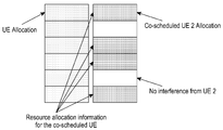
- FIGURE 8 illustrates an indication of resource assignments for a UE having an overlapping allocation of resource blocks in accordance with various embodiments of the present disclosure.
- UEs may be scheduled with an overlapping allocation of RBs in frequency. While this scheduling scheme may somewhat limit scheduling flexibility, this scheduling scheme may reduce the signaling overhead for interference reduction.
- the network entity may define a group of RBs over which the same set of UEs is allocated the same set of DMRS ports. Since the amount of coded data sent to each UE may be different, a UE may have to further detect the presence or absence of a UE allocation in the RBs on the assigned port.
- the network entity may signal information related to the resource allocation information of a co-scheduled UE.
- the 3GPP Specification 36.212 describes the signaling of resource allocation to a UE.
- a resource allocation header (resource allocation type 0 / type 1) - 1 bit as defined in section 7.1.6 (of 36.213). If downlink bandwidth is less than or equal to 10 PRBs, there is no resource allocation header, and resource allocation type 0 is assumed.
- Resource block assignment for resource allocation type 0 as defined in section 7.1.6.1 of [36.213] and bits provide the resource allocation; for resource allocation type 1 as defined in section 7.1.6.2 (of 36.213) bits of this field are used as a header specific to this resource allocation type to indicate the selected resource blocks subset, 1 bit indicates a shift of the resource allocation span, and bits provide the resource allocation, where the value of P depends on the number of DL resource blocks as indicated in section 7.1.6.1 (of 36.213).
- the resource allocation defined includes a bitmap or a selection from a set of localized or distributed resource blocks and virtual resource blocks or resource block groups. This resource allocation allows sufficient flexibility to share the resources in frequency to different UEs. Further, a resource allocation header indicates a selection between the resource allocation types.
- a co-channel resource allocation block assignment field and co-channel resource allocation header may be defined to indicate the resource allocation information of a co-scheduled UE.
- the UE may assume the interference from that UE only in the set of overlapping resources. For example, as illustrated in FIGURE 8, the UE assumes interference from only the co-scheduled/overlapping blocks and no interference is assumed in the non-overlapping blocks.
- the set of overlapping resources over which an interfering UE is scheduled may be directly indicated with a resource allocation header and a resource block assignment field.
- the set of overlapping resources over which an interfering UE is not scheduled may be directly indicated with a resource allocation header and a resource block assignment field.
- a set of resource assignments may be pre-defined (e.g., by higher layer signaling or fixed) and dynamic signaling may be used to select between the different resource assignments to reduce overhead in DCI.
- co-channel resource allocation may be implicitly determined by the UE using one or more of the other parameters signaled for the other UE, (e.g., port index, port RNTI, a pre-configured group ID for similarly scheduled UEs).
- the indicated resource allocation corresponds to the resources over which the UE can expect interference and the associated signaled interference reduction parameters (e.g., MCS, port RNTI, port ID, etc.) are applicable.
- the base station may transmit the PDSCH using DM-RS ports that are scrambled with the port’s scrambling ID instead of the C-RNTI of the UE, and the network entity assigns each DM-RS port a different port scrambling ID.
- the scrambling initialization equation may be calculated according to equation 3 below:
- the UE can be configured or controlled by the network entity to perform PDSCH descrambling using the legacy method or the descrambling method described above.
- This configuration/control can be semi-static (i.e. signaled by a higher layer), for example, via transmission mode configuration.
- Table 8 provides one example of an illustration of a higher layer configuration of the PDSCH scrambling method.
- the configuration or control can also be dynamic.
- the UE may switch between the legacy method and the method of descrambling using the port scrambling ID, depending on the control information received from PDCCH or ePDCCH.
- the dynamic control may be indicated using 1-bit signaling in the DCI format (for DL assignment). For example, a “0” indicates the legacy method should be used to receive the corresponding PDSCH, and a “1” indicates that method of descrambling using the port scrambling ID should be used to receive the corresponding PDSCH.
- the DM-RS ports assigned or the rank assigned are examples of the DM-RS ports assigned or the rank assigned.
- the DM-RS port(s) assigned are 7, 7 and 8, 9, 9 and 10, or, more generally, if the rank assigned is less than or equal to some specified number x where x can e.g. be 2, the port scrambling ID method is used (i.e., MU-MIMO operation may be assumed). Otherwise, the UE assumes that the legacy method is used (i.e., SU-MIMO operation may be assumed).
- the type of DCI format may be used to indicate the PDSCH scrambling method. For example, if DCI format 1A is received, the legacy method is assumed to be used to descramble the corresponding PDSCH, else if DCI format 2C (or reference DCI format) is received, the port scrambling ID method is used to descramble the corresponding PDSCH. In another example, further dependency on where the DCI format was received may be used to indicate the PDSCH scrambling method.
- the legacy method is used to descramble the corresponding PDSCH
- the port scrambling ID method is used to descramble the corresponding PDSCH.
- One benefit of scrambling PDSCH with port scrambling ID instead of the C-RNTI may include facilitation of MU-interference cancelation and/or suppression for PDSCH.
- the port scrambling ID method allows the UE to descramble and then decode the interfering PDSCH, which can then be used for interference cancelation/suppression as discussed above, for example, with regard to the feedback loop 730 in FIGURE 7.
- the signaling of the port scrambling ID signaling may include a predefined port scrambling ID for each DM-RS port.
- Table 9 illustrates one example of a mapping for 8 ports. However, mapping for fewer numbers of DM-RS ports is also possible (e.g. just ports 7, 8, 9, and 10).
- the UE is able to derive the port scrambling ID used for the PDSCH of the interfering UE.
- a higher layer configuration of port scrambling ID for each DM-RS port may be used to indicated the port scrambling ID to the UE.
- Table 10 illustrates one example of a mapping for 8 ports. However, mapping for fewer numbers of DM-RS ports is also possible (e.g. just ports 7, 8, 9, and 10).
- the number of bits for the ID value can be log2 (number of DM-RS ports) (i.e., 3 for 8 ports and 2 for 4 ports) or the number of bits may be of the same length as the C-RNTI (i.e., 16 bits).
- the UE if the UE is signaled or detects blindly the interfering UE’s port(s), the UE is able to derive the port scrambling ID used for the PDSCH of the interfering UE.
- the higher layering signaling of Table 10 is common for all MU UEs may be broadcasted.
- the UE should also be signaled the port-scrambling ID of the interfering UE or the UE should blindly detect the port scrambling ID of the interfering UE.
- Signaling of the DM-RS port scrambling ID of the interfering UE has significantly lower overhead than signaling of C-RNTI. For example, if 8 ports are defined, only 3 bits are required for signaling of the DM-RS port scrambling ID, compared to 16 bits for C-RNTI signaling.
- FIGURE 9 illustrates a process for identifying resource scheduling for a UE in a multiple-user multiple-input multiple-output wireless communication system in accordance with various embodiments of the present disclosure.
- the process depicted in FIGURE 9 may be performed by the receiver 310 in FIGURE 3.
- the process may also be implemented by the UE 700 in FIGURE 7.
- the process begins by the UE receiving downlink control information (step 905).
- the UE may receive downlink control information in control signaling in a DCI format.
- the downlink control information may be statically or semi-statically signaled. Alternatively, the downlink control information may be dynamically signaled, for example, in each downlink subframe.
- the UE then identifies DM-RS port(s) assigned to the UE (step 910). For example, in step 910, the UE may identify the DM-RS port(s) for the UE in the downlink control information.
- the UE then identifies a PDSCH EPRE to DM-RS EPRE ratio (step 915). For example, in step 915, the UE may identify the PDSCH EPRE to DM-RS EPRE ratio and whether rate matching is used from a jointly encoded signal bit field in the downlink control information. For example, the UE may identify the PDSCH EPRE to DM-RS EPRE ratio as 0 dB or -3 dB. The UE may also identify a number layers, a scrambling identifier, and whether rate matching is used from a jointly encoded message in the downlink control information.
- the UE may also identify information about one or more interfering UEs including at least one of a modulation and coding scheme of the one or more interfering UEs, one or more port(s) assigned to the one or more interfering UEs, a number of the one or more interfering UEs, a UE identifier for the one or more interfering UEs, or a DM-RS port scrambling identifier for the one or more interfering UEs.
- the UE may also identify a DM-RS port scrambling identifier for a DM-RS port assigned to an interfering UE to use to calculate an initialization value for a scrambling sequence for resources assigned to the interfering UE and reduce interference.
- the UE may also identify whether an interfering UE is allocated a group of resource blocks that overlaps with resource blocks assigned to the UE to reduce interference.
- the UE then receives a downlink subframe (step 920).
- the UE then identifies resource block(s) including data intended for the UE (step 925).
- the UE then identifies the data intended for the UE in the resource block (step 930).
- the UE may identify the data using the one or more DM-RS port(s) and the PDSCH EPRE to DM-RS EPRE ratio.
- the resource block in the downlink subframe may include data for multiple users in the wireless communication system. Thereafter, the UE returns to step 920 to receive and decode data from additional downlink subframes.
- FIGURE 10 illustrates a process for scheduling resources in a multiple-user multiple-input multiple-output wireless communication system in accordance with various embodiments of the present disclosure.
- the process depicted in FIGURE 10 may be performed by the transmitter 305 in FIGURE 3.
- the process may also be implemented by a network entity, such as an eNB, RRH, relay station, underlay base station, GW, or BSC.
- a network entity such as an eNB, RRH, relay station, underlay base station, GW, or BSC.
- the process begins by the network entity identifying DM-RS port(s) to assign to the UE (step 1005).
- the network entity then identifies a PDSCH EPRE to DM-RS EPRE ratio (step 1010).
- the network entity may use the PDSCH EPRE to DM-RS EPRE ratio to multiplex data in a same frequency resource.
- the network entity then sends downlink control information (step 1015).
- the network entity may send the control information to the UE to indicate the DM-RS port(s) and PDSCH EPRE to DM-RS EPRE ratio.
- the downlink control information may be statically or semi-statically signaled. Alternatively, the downlink control information may be dynamically signaled, for example, in each downlink subframe.
- the PDSCH EPRE to DM-RS EPRE ratio and whether rate matching is used may be jointly encoded into a signal bit field in the downlink control information.
- the one or more DM-RS port(s) assigned to the UE, a number layers, a scrambling identifier, the PDSCH EPRE to DM-RS EPRE ratio, and whether rate matching is used may be jointly encoded in the downlink control information.
- the downlink control information may include an indication of information about one or more interfering UEs including at least one of a modulation and coding scheme of the one or more interfering UEs, one or more port(s) assigned to the one or more interfering UEs, a number of the one or more interfering UEs, a UE identifier for the one or more interfering UEs, or a DM-RS port scrambling identifier for the one or more interfering UEs.
- the downlink control information may include an indication of a DM-RS port scrambling identifier for a DM-RS port assigned to an interfering UE.
- the downlink control information may include an indication of an initialization value for a scrambling sequence for resources assigned to the interfering UE using the DM-RS port scrambling identifier.
- the downlink control information may include an indication of whether an interfering UE is allocated a group of resource blocks that overlaps with resource blocks assigned to the UE.
- the network entity then transmits downlink subframes in accordance with the scheduled resources (step 1020). For example, in step 1020, the network entity may transmit the downlink subframes according to the one or more DM-RS port(s) assigned to the UE and the PDSCH EPRE to DM-RS EPRE ratio.
- FIGURES 9 and 10 illustrate examples of processes for scheduling resources and identifying resource scheduling in a MU-MIMO wireless communication system, respectively, various changes could be made to FIGURES 9 and 10. For example, while shown as a series of steps, various steps in each figure could overlap, occur in parallel, occur in a different order, or occur multiple times.
Landscapes
- Engineering & Computer Science (AREA)
- Signal Processing (AREA)
- Computer Networks & Wireless Communication (AREA)
- Mobile Radio Communication Systems (AREA)
Abstract
L'invention concerne des procédés et des appareils permettant d'ordonnancer des ressources et d'identifier l'ordonnancement des ressources dans un système de communication sans fil MIMO MU. Un procédé d'identification de l'ordonnancement des ressources pour un équipement utilisateur comprend la réception d'informations de commande de liaison descendante ; l'identification, à partir des informations de commande de liaison descendante, d'un ou plusieurs ports DM-RS affectés à l'équipement utilisateur et d'un rapport PDSCH EPRE/DM-RS EPRE ; et l'identification de données destinées à l'équipement utilisateur dans un bloc de ressources dans une sous-trame de liaison descendante en utilisant lesdits un ou plusieurs ports DM-RS et le rapport PDSCH EPRE/DM-RS EPRE. Un procédé d'ordonnancement des ressources comprend l'identification d'un ou plusieurs ports DM-RS à affecter à un équipement utilisateur et d'un rapport PDSCH EPRE/DM-RS EPRE afin d'identifier des données destinées à l'équipement utilisateur dans un bloc de ressources dans une sous-trame de liaison descendante ; et l'inclusion d'une indication desdits un ou plusieurs ports DM-RS et du rapport PDSCH EPRE/DM-RS EPRE dans les informations de commande de liaison descendante.
Priority Applications (2)
| Application Number | Priority Date | Filing Date | Title |
|---|---|---|---|
| CN201380018211.1A CN104247359B (zh) | 2012-04-04 | 2013-03-29 | 用于支持无线通信系统的高阶多用户多入多出操作的装置及方法 |
| JP2015504480A JP6208211B2 (ja) | 2012-04-04 | 2013-03-29 | 無線通信システムのための高次多重ユーザ多入力多出力動作をサポートする装置及び方法 |
Applications Claiming Priority (6)
| Application Number | Priority Date | Filing Date | Title |
|---|---|---|---|
| US201261620318P | 2012-04-04 | 2012-04-04 | |
| US61/620,318 | 2012-04-04 | ||
| US201261668877P | 2012-07-06 | 2012-07-06 | |
| US61/668,877 | 2012-07-06 | ||
| US13/841,791 | 2013-03-15 | ||
| US13/841,791 US9019924B2 (en) | 2012-04-04 | 2013-03-15 | High-order multiple-user multiple-input multiple-output operation for wireless communication systems |
Publications (1)
| Publication Number | Publication Date |
|---|---|
| WO2013151277A1 true WO2013151277A1 (fr) | 2013-10-10 |
Family
ID=48082911
Family Applications (1)
| Application Number | Title | Priority Date | Filing Date |
|---|---|---|---|
| PCT/KR2013/002629 WO2013151277A1 (fr) | 2012-04-04 | 2013-03-29 | Appareil et procédé pour prendre en charge un fonctionnement à entrée multiple sortie multiple multi-utilisateur d'ordre supérieur pour les systèmes de communication sans fil |
Country Status (5)
| Country | Link |
|---|---|
| US (2) | US9019924B2 (fr) |
| EP (2) | EP3726906B1 (fr) |
| JP (3) | JP6208211B2 (fr) |
| CN (2) | CN104247359B (fr) |
| WO (1) | WO2013151277A1 (fr) |
Cited By (7)
| Publication number | Priority date | Publication date | Assignee | Title |
|---|---|---|---|---|
| JP2017505068A (ja) * | 2014-01-31 | 2017-02-09 | クゥアルコム・インコーポレイテッドQualcomm Incorporated | 干渉管理情報シグナリング |
| JPWO2015107978A1 (ja) * | 2014-01-15 | 2017-03-23 | シャープ株式会社 | 端末装置、基地局装置、および集積回路 |
| JPWO2015107771A1 (ja) * | 2014-01-15 | 2017-03-23 | シャープ株式会社 | 端末装置、基地局装置、および集積回路 |
| JPWO2016129417A1 (ja) * | 2015-02-09 | 2017-05-25 | 三菱電機株式会社 | 通信装置 |
| JP2017516426A (ja) * | 2014-07-16 | 2017-06-15 | エルジー エレクトロニクス インコーポレイティド | 無線通信システムにおいてチャネルを推定する方法及び装置 |
| JP2017539136A (ja) * | 2014-11-07 | 2017-12-28 | 富士通株式会社 | Dm−rs情報の指示方法、装置及び通信システム |
| US9948369B2 (en) | 2014-04-02 | 2018-04-17 | Zte Corporation | Method and apparatus for implementing transparent multi-user multiple-input multiple-output transmission |
Families Citing this family (61)
| Publication number | Priority date | Publication date | Assignee | Title |
|---|---|---|---|---|
| KR101606803B1 (ko) | 2010-04-29 | 2016-03-28 | 엘지전자 주식회사 | 제어정보의 전송방법 및 기지국과, 제어정보의 수신방법 및 사용자기기 |
| CN103581090B (zh) * | 2012-07-26 | 2016-12-28 | 华为技术有限公司 | 导频信号发送方法和装置 |
| US9407302B2 (en) * | 2012-12-03 | 2016-08-02 | Intel Corporation | Communication device, mobile terminal, method for requesting information and method for providing information |
| GB2512268B (en) * | 2012-12-03 | 2015-02-18 | Broadcom Corp | Interference cancellation |
| US10841037B2 (en) * | 2013-01-22 | 2020-11-17 | Qualcomm Incorporated | Managing interference in a network |
| JP5894105B2 (ja) * | 2013-04-04 | 2016-03-23 | 株式会社Nttドコモ | 無線基地局、ユーザ端末及び無線通信方法 |
| US9813124B2 (en) * | 2013-11-27 | 2017-11-07 | Mediatek Inc. | Methods for codeword level interference cancellation with network assistance |
| US9641310B2 (en) * | 2013-12-13 | 2017-05-02 | Qualcomm Incorporated | Network assisted interference cancellation signaling |
| EP3079286B1 (fr) * | 2013-12-26 | 2019-11-06 | Huawei Technologies Co., Ltd. | Procédé et appareil de station de base pour le traitement de données |
| JP6723150B2 (ja) * | 2014-03-20 | 2020-07-15 | シャープ株式会社 | 端末装置および集積回路 |
| KR102544449B1 (ko) * | 2014-07-28 | 2023-06-16 | 엘지전자 주식회사 | 무선 통신 시스템에서 무선 신호 송수신 방법 및 장치 |
| US11445493B2 (en) | 2014-07-31 | 2022-09-13 | Lg Electronics Inc. | Method and apparatus for transceiving wireless signal in wireless communication system |
| CN107078874B (zh) * | 2014-09-24 | 2020-09-04 | Lg 电子株式会社 | 无线通信系统中发送和接收参考信号的方法及其装置 |
| US10555314B2 (en) * | 2014-10-07 | 2020-02-04 | Hfi Innovation Inc. | Signaling of network-assisted intra-cell interference cancellation and suppression |
| WO2016072887A1 (fr) * | 2014-11-04 | 2016-05-12 | Telefonaktiebolaget L M Ericsson (Publ) | Allocation de ressources se chevauchant partiellement à des dispositifs de communication |
| CN105681007B (zh) * | 2014-11-19 | 2020-11-06 | 北京三星通信技术研究有限公司 | 参考信号的发送、接收方法及装置和调度方法及装置 |
| WO2016127309A1 (fr) * | 2015-02-10 | 2016-08-18 | Qualcomm Incorporated | Amélioration du signal de référence de démodulation pour un système mimo-mu d'ordre supérieur |
| CN105992380B (zh) * | 2015-03-04 | 2020-09-15 | 株式会社Ntt都科摩 | 基站、移动台和下行链路调度方法 |
| CN106161300B (zh) * | 2015-03-25 | 2019-05-24 | 上海诺基亚贝尔股份有限公司 | 用于动态实施频率复用的方法和分析器 |
| US9769075B2 (en) * | 2015-04-01 | 2017-09-19 | Honeywell International Inc. | Interference cognizant network scheduling |
| US9769082B2 (en) | 2015-04-01 | 2017-09-19 | Honeywell International Inc. | System and method for network bandwidth, buffers and timing management using hybrid scheduling of traffic with different priorities and guarantees |
| CN107852730A (zh) * | 2015-04-09 | 2018-03-27 | 华为技术有限公司 | 传输参数信息的方法及装置、基站及被干扰用户设备 |
| CN106162890B (zh) | 2015-04-14 | 2020-02-18 | 中国移动通信集团公司 | 一种解调参考信号dmrs端口的指示方法、装置及基站 |
| CN106209300B (zh) * | 2015-04-30 | 2019-12-13 | 电信科学技术研究院 | 一种控制信息发送方法和接收方法及发射机、接收机 |
| WO2016179781A1 (fr) * | 2015-05-11 | 2016-11-17 | 华为技术有限公司 | Procédé d'indication d'informations de commande, station de base, dispositif d'utilisateur, et système de communication |
| CN107005982B (zh) * | 2015-05-11 | 2020-02-21 | 华为技术有限公司 | 基于半正交传输的通信方法和设备 |
| CN106411485A (zh) * | 2015-07-28 | 2017-02-15 | 中兴通讯股份有限公司 | 导频功率通知、获取方法及装置 |
| CN107852205B (zh) * | 2015-08-12 | 2021-06-04 | 苹果公司 | 多用户多输入多输出通信系统和方法 |
| WO2017026457A1 (fr) * | 2015-08-13 | 2017-02-16 | 株式会社Nttドコモ | Procédé d'ordonnancement de ressources sans fil, station de base sans fil, et station mobile |
| GB2541390B (en) * | 2015-08-14 | 2021-10-20 | Tcl Communication Ltd | Systems and methods for multi-user communication |
| CN106470088B (zh) * | 2015-08-14 | 2021-06-15 | 中兴通讯股份有限公司 | Dmrs端口或映射关系的通知、确定方法及装置 |
| CN106470487A (zh) * | 2015-08-19 | 2017-03-01 | 中国移动通信集团公司 | 功率分配指示方法、相关设备和系统 |
| US10080244B2 (en) * | 2015-08-28 | 2018-09-18 | Qualcomm Incorporated | Random access channel design for narrowband wireless communication |
| CN106685580B (zh) | 2015-11-06 | 2020-03-03 | 中兴通讯股份有限公司 | 数据处理方法及装置 |
| US20200028856A1 (en) * | 2018-07-23 | 2020-01-23 | Cyber 2.0 (2015) LTD | Port scrambling usage in heterogeneous networks |
| CN106973437B (zh) * | 2016-01-13 | 2021-10-01 | 华为技术有限公司 | 一种参考信号的配置方法及设备 |
| CN107302421B (zh) * | 2016-04-08 | 2021-05-18 | 华为技术有限公司 | 一种功率配置方法及设备 |
| CN107623541B (zh) | 2016-07-13 | 2021-06-15 | 华为技术有限公司 | 一种下行控制信令指示的方法及相关设备 |
| US10631329B2 (en) * | 2016-08-12 | 2020-04-21 | Qualcomm Incorporated | Non-coherent joint transmission techniques |
| US11172444B2 (en) * | 2016-10-10 | 2021-11-09 | Qualcomm Incorporated | Techniques for power control and management |
| US11134474B2 (en) * | 2016-10-21 | 2021-09-28 | Qualcomm Incorporated | Multi-user multiple input multiple output operation with heterogeneous numerology systems |
| CN108270711B (zh) * | 2017-01-04 | 2021-12-03 | 华为技术有限公司 | 传输参考信号的方法、设备和系统 |
| WO2018126894A1 (fr) * | 2017-01-06 | 2018-07-12 | 华为技术有限公司 | Procédé de configuration de puissance, et dispositif associé |
| CN108282202B (zh) | 2017-01-06 | 2021-09-14 | 华为技术有限公司 | 一种功率配置方法及相关设备 |
| WO2018129700A1 (fr) * | 2017-01-13 | 2018-07-19 | Qualcomm Incorporated | Attribution de puissance pour canal de données et signaux de référence |
| CN108347324B (zh) * | 2017-01-25 | 2022-05-31 | 华为技术有限公司 | 通信方法和网络设备 |
| WO2018184169A1 (fr) | 2017-04-06 | 2018-10-11 | Qualcomm Incorporated | Indication de chargement de port d'utilisateur multiple |
| CN109891818B (zh) * | 2017-08-08 | 2023-06-06 | Lg电子株式会社 | 用于在无线通信系统中发送/接收参考信号的方法及其装置 |
| US10652002B2 (en) * | 2017-08-31 | 2020-05-12 | Samsung Electronics Co., Ltd. | Method and apparatus for re mapping and rate matching for 5G next radio system |
| WO2019066539A1 (fr) * | 2017-09-28 | 2019-04-04 | 엘지전자 주식회사 | Procédé d'émission/réception de données de liaison descendante et dispositif associé |
| WO2019061326A1 (fr) * | 2017-09-29 | 2019-04-04 | 富士通株式会社 | Port d'antenne, procédé et appareil d'indication de quantité de couches de données, et système de communication |
| CN108111444A (zh) | 2017-11-17 | 2018-06-01 | 中兴通讯股份有限公司 | 信号加扰、解扰方法及装置 |
| CN111869148B (zh) * | 2018-01-12 | 2023-08-01 | 瑞典爱立信有限公司 | 用于物理下行链路信道和非周期性干扰测量的资源元素 |
| CN110167040A (zh) * | 2018-02-11 | 2019-08-23 | 索尼公司 | 无线通信系统中的装置和方法、计算机可读存储介质 |
| CN110324109B (zh) * | 2018-03-29 | 2021-11-26 | 北京紫光展锐通信技术有限公司 | Pdsch速率匹配方法、装置、用户终端及计算机可读存储介质 |
| EP3780777A4 (fr) * | 2018-04-06 | 2021-11-24 | Ntt Docomo, Inc. | Terminal utilisateur |
| US10849115B2 (en) * | 2018-09-10 | 2020-11-24 | Apple Inc. | Downlink control channel design in new radio systems |
| US11297621B2 (en) | 2018-11-02 | 2022-04-05 | Qualcomm Incorporated | Cyclic prefix orthogonal frequency division multiplexing sequence configuration of a downlink / uplink |
| US20220407646A1 (en) * | 2019-06-21 | 2022-12-22 | Ntt Docomo, Inc. | Terminal and radio communication method |
| WO2022140778A1 (fr) * | 2020-12-21 | 2022-06-30 | Cohere Technologies, Inc. | Multiplexage spatial de différentes technologies radio |
| US11617184B2 (en) * | 2021-01-04 | 2023-03-28 | Qualcomm Incorporated | Allocation of frequency resources based on narrowband isolated frequencies |
Citations (2)
| Publication number | Priority date | Publication date | Assignee | Title |
|---|---|---|---|---|
| US20050043031A1 (en) * | 2003-08-18 | 2005-02-24 | Samsung Electronics Co., Ltd. | Apparatus and method for scheduling resource in a multiuser MIMO radio communication system |
| US20110194593A1 (en) * | 2009-08-18 | 2011-08-11 | Qualcomm Incorporated | DL MU-MIMO operation in LTE-A |
Family Cites Families (34)
| Publication number | Priority date | Publication date | Assignee | Title |
|---|---|---|---|---|
| US8238455B2 (en) * | 2008-01-07 | 2012-08-07 | Samsung Electronics Co., Ltd. | Methods and apparatus for downlink PDSCH power setting |
| US8194602B2 (en) * | 2008-03-19 | 2012-06-05 | Futurewei Technologies, Inc. | System and method for downlink control signal structure for multi-user MIMO |
| US9008007B2 (en) | 2008-09-23 | 2015-04-14 | Interdigital Patent Holdings, Inc | Method for signaling MU-MIMO parameters |
| EP2380287B1 (fr) * | 2008-12-18 | 2014-09-24 | Nec Corporation | Procédés et systèmes pour transporter des informations de scheduling d'utilisateurs superposés dans un système OFDMA MU-MIMO |
| US9094167B2 (en) | 2009-02-02 | 2015-07-28 | Samsung Electronics Co., Ltd. | System and method for multi-user and multi-cell MIMO transmissions |
| US20110142107A1 (en) * | 2009-06-16 | 2011-06-16 | Kyle Jung-Lin Pan | Rank Adaptive Cyclic Shift for Demodulation Reference Signal |
| EP2280492A1 (fr) * | 2009-07-07 | 2011-02-02 | ST-Ericsson (France) SAS | Procédé pour l'annulation d'interférences inter-cellules dans un système OFDM synchronisé et appareil correspondant |
| US20110019776A1 (en) * | 2009-07-24 | 2011-01-27 | Interdigital Patent Holdings, Inc. | Method and apparatus for obtaining port index information |
| WO2011016691A2 (fr) * | 2009-08-06 | 2011-02-10 | 엘지전자 주식회사 | Procédé et appareil d'émission de signaux montants dans un système de communication sans fil pour la prise en charge d'une transmission par antennes multiples |
| US8300587B2 (en) * | 2009-08-17 | 2012-10-30 | Nokia Corporation | Initialization of reference signal scrambling |
| CN102598568B (zh) * | 2009-10-29 | 2015-03-18 | 联想创新有限公司(香港) | 用于下行链路mimo的下行链路控制信令传输的方法和用户设备 |
| WO2011090353A2 (fr) * | 2010-01-22 | 2011-07-28 | 엘지전자 주식회사 | Procédé et appareil de fourniture d'informations de commande de liaison descendante dans un système de communication sans fil mimo |
| EP3761550B1 (fr) * | 2010-02-11 | 2021-07-07 | Samsung Electronics Co., Ltd. | Procédé pour l'indication d'un port d'antenne dm-rs dans un système de communication sans fil |
| JP2011217075A (ja) * | 2010-03-31 | 2011-10-27 | Sharp Corp | 送信装置、受信装置、通信システム、通信方法および集積回路 |
| WO2011134107A1 (fr) * | 2010-04-30 | 2011-11-03 | Telefonaktiebolaget L M Ericsson (Publ) | Conception d'un système de signalisation de commande pour un mode de transmission lte-a en liaison descendante |
| CN102264123B (zh) * | 2010-05-26 | 2014-07-23 | 电信科学技术研究院 | 一种pdsch功率分配方法及装置 |
| JP5662448B2 (ja) * | 2010-07-21 | 2015-01-28 | パナソニック インテレクチュアル プロパティ コーポレーション オブアメリカPanasonic Intellectual Property Corporation of America | 基地局装置、端末装置、送信方法及び受信方法 |
| CN107196718B (zh) * | 2010-09-30 | 2020-12-18 | Lg 电子株式会社 | 用于在无线通信系统中通过中继节点报告信道质量指示符的方法及其装置 |
| US9544108B2 (en) * | 2011-02-11 | 2017-01-10 | Qualcomm Incorporated | Method and apparatus for enabling channel and interference estimations in macro/RRH system |
| JP5784152B2 (ja) * | 2011-02-11 | 2015-09-24 | インターデイジタル パテント ホールディングス インコーポレイテッド | 拡張された制御チャネルのシステムおよび方法 |
| CN102684850B (zh) * | 2011-03-11 | 2017-07-04 | 夏普株式会社 | 信道状态信息反馈方法、用户设备和基站 |
| WO2012134335A1 (fr) * | 2011-04-01 | 2012-10-04 | Intel Corporation | Technique de transmission conjointe multi-flux pour réseau de communication sans fil |
| CN102201897B (zh) * | 2011-04-29 | 2017-09-15 | 中兴通讯股份有限公司 | 信道状态信息处理方法、装置及系统 |
| CN102201879B (zh) * | 2011-06-20 | 2013-06-19 | 合肥东芯通信股份有限公司 | Lte系统干扰噪声的测量方法及设备 |
| US8537862B2 (en) * | 2011-06-30 | 2013-09-17 | Blackberry Limited | Transmit downlink control information with higher order modulation |
| US9307422B2 (en) * | 2011-07-07 | 2016-04-05 | Lg Electronics Inc. | Method and apparatus for performing a channel measurement through a receiving end in a wireless communication system |
| US9025574B2 (en) * | 2011-08-12 | 2015-05-05 | Blackberry Limited | Methods of channel state information feedback and transmission in coordinated multi-point wireless communications system |
| CN102368869B (zh) * | 2011-11-23 | 2014-07-30 | 武汉邮电科学研究院 | Fdd-lte下行pdsch功率控制在dsp中实现的方法 |
| US9450719B2 (en) * | 2012-03-05 | 2016-09-20 | Lg Electronics Inc. | Method and apparatus for transmitting or receiving downlink signal |
| CA2865770C (fr) * | 2012-04-19 | 2020-12-01 | Samsung Electronics Co., Ltd. | Procede et appareil pour l'identification de ports de symboles de reference presque colocalises dans les systemes de communication multipoint coordonnee |
| US9923684B2 (en) | 2013-01-09 | 2018-03-20 | Samsung Electronics Co., Ltd. | Methods to support inter-eNodeB CoMP |
| US9160515B2 (en) * | 2013-04-04 | 2015-10-13 | Intel IP Corporation | User equipment and methods for handover enhancement using scaled time-to-trigger and time-of-stay |
| US9479298B2 (en) * | 2013-07-08 | 2016-10-25 | Intel IP Corporation | Demodulation reference signals (DMRS)for side information for interference cancellation |
| US10623157B2 (en) | 2017-04-30 | 2020-04-14 | Lg Electronics Inc. | Method for transmitting and receiving DM-RS in wireless communication system and apparatus therefor |
-
2013
- 2013-03-15 US US13/841,791 patent/US9019924B2/en not_active Ceased
- 2013-03-29 WO PCT/KR2013/002629 patent/WO2013151277A1/fr active Application Filing
- 2013-03-29 JP JP2015504480A patent/JP6208211B2/ja active Active
- 2013-03-29 CN CN201380018211.1A patent/CN104247359B/zh active Active
- 2013-03-29 CN CN201710872763.9A patent/CN107437962B/zh active Active
- 2013-04-03 EP EP20177220.9A patent/EP3726906B1/fr active Active
- 2013-04-03 EP EP13162199.7A patent/EP2648448B1/fr active Active
-
2015
- 2015-10-29 US US14/927,312 patent/USRE49548E1/en active Active
-
2017
- 2017-09-06 JP JP2017171147A patent/JP6469786B2/ja active Active
-
2019
- 2019-01-16 JP JP2019005020A patent/JP6832964B2/ja active Active
Patent Citations (2)
| Publication number | Priority date | Publication date | Assignee | Title |
|---|---|---|---|---|
| US20050043031A1 (en) * | 2003-08-18 | 2005-02-24 | Samsung Electronics Co., Ltd. | Apparatus and method for scheduling resource in a multiuser MIMO radio communication system |
| US20110194593A1 (en) * | 2009-08-18 | 2011-08-11 | Qualcomm Incorporated | DL MU-MIMO operation in LTE-A |
Non-Patent Citations (3)
| Title |
|---|
| INTERDIGITAL COMMUNICATIONS ET AL.: "Discussion on transparency of LTE-A MU- MIMO", RI-103271, 3GPP TSG RAN WG1 # 61, 10 May 2010 (2010-05-10), MONTREAL, CANADA * |
| MOTOROLA: "Control Signaling for LTE Rel-9 Enhanced DL transmission", R1-093 955, 3GPP TSG RAN WG1 #58 BIS, 12 October 2009 (2009-10-12), MIYAZAKI, JAPAN * |
| NEC GROUP: "Downlink control signalling support for SU/MU-MIMO", R1-094730, 3GPP TSG-RAN WG1 MEETING #59, 9 November 2009 (2009-11-09), JEJU, KOREA * |
Cited By (12)
| Publication number | Priority date | Publication date | Assignee | Title |
|---|---|---|---|---|
| JPWO2015107978A1 (ja) * | 2014-01-15 | 2017-03-23 | シャープ株式会社 | 端末装置、基地局装置、および集積回路 |
| JPWO2015107771A1 (ja) * | 2014-01-15 | 2017-03-23 | シャープ株式会社 | 端末装置、基地局装置、および集積回路 |
| US10171196B2 (en) | 2014-01-15 | 2019-01-01 | Sharp Kabushiki Kaisha | Terminal device, base station apparatus, and integrated circuit |
| US11038612B2 (en) | 2014-01-15 | 2021-06-15 | Sharp Kabushiki Kaisha | Terminal device, base station apparatus, and integrated circuit |
| JP2017505068A (ja) * | 2014-01-31 | 2017-02-09 | クゥアルコム・インコーポレイテッドQualcomm Incorporated | 干渉管理情報シグナリング |
| US10256855B2 (en) | 2014-01-31 | 2019-04-09 | Qualcomm Incorporated | Interference management information signaling |
| US9948369B2 (en) | 2014-04-02 | 2018-04-17 | Zte Corporation | Method and apparatus for implementing transparent multi-user multiple-input multiple-output transmission |
| JP2017516426A (ja) * | 2014-07-16 | 2017-06-15 | エルジー エレクトロニクス インコーポレイティド | 無線通信システムにおいてチャネルを推定する方法及び装置 |
| US10439846B2 (en) | 2014-07-16 | 2019-10-08 | Lg Electronics Inc. | Method and device for estimating channel in wireless communication system |
| US10965500B2 (en) | 2014-07-16 | 2021-03-30 | Lg Electronics Inc. | Method and device for estimating channel in wireless communication system |
| JP2017539136A (ja) * | 2014-11-07 | 2017-12-28 | 富士通株式会社 | Dm−rs情報の指示方法、装置及び通信システム |
| JPWO2016129417A1 (ja) * | 2015-02-09 | 2017-05-25 | 三菱電機株式会社 | 通信装置 |
Also Published As
| Publication number | Publication date |
|---|---|
| CN107437962B (zh) | 2020-09-29 |
| EP2648448B1 (fr) | 2020-06-24 |
| CN104247359A (zh) | 2014-12-24 |
| JP6469786B2 (ja) | 2019-02-13 |
| JP2015518318A (ja) | 2015-06-25 |
| USRE49548E1 (en) | 2023-06-06 |
| JP2018011333A (ja) | 2018-01-18 |
| EP3726906A1 (fr) | 2020-10-21 |
| JP6832964B2 (ja) | 2021-02-24 |
| US9019924B2 (en) | 2015-04-28 |
| JP2019092174A (ja) | 2019-06-13 |
| CN107437962A (zh) | 2017-12-05 |
| JP6208211B2 (ja) | 2017-10-04 |
| US20130265951A1 (en) | 2013-10-10 |
| EP3726906B1 (fr) | 2023-04-26 |
| CN104247359B (zh) | 2017-10-20 |
| EP2648448A1 (fr) | 2013-10-09 |
Similar Documents
| Publication | Publication Date | Title |
|---|---|---|
| WO2013151277A1 (fr) | Appareil et procédé pour prendre en charge un fonctionnement à entrée multiple sortie multiple multi-utilisateur d'ordre supérieur pour les systèmes de communication sans fil | |
| WO2011129628A2 (fr) | Systèmes et procédés de groupage de blocs de ressources dans un système de communications sans fil | |
| KR101838203B1 (ko) | 무선 통신 시스템에서 다중 사용자 다중 입력 다중 출력 전송을 위한 방법 및 장치 | |
| WO2018026220A1 (fr) | Procédé et appareil de signalisation de signal de référence pour des communications sans fil avancées | |
| WO2014069937A1 (fr) | Schéma de transmission et hypothèse de quasi colocalisation de ports d'antenne pour pdsch de mode de transmission 10 pour lte avancée | |
| WO2016204456A1 (fr) | Procédé et appareil d'émission et de réception pour émettre un signal en utilisant une bande étroite dans un système de communication cellulaire sans fil | |
| WO2013032202A2 (fr) | Procédé et équipement utilisateur pour recevoir des signaux de liaison descendante, et procédé et station de base pour transmettre des signaux de liaison descendante | |
| WO2011052911A2 (fr) | Procédé d'émission/réception d'un signal de référence descendant, et station de base et équipement utilisateur l'utilisant | |
| WO2013141661A1 (fr) | Procédé et appareil de conception de mode de transmission pour la porteuse d'extension d'un système lte avancé | |
| WO2010087681A2 (fr) | Système et procédé pour émissions mimo multiutilisateurs et multi-cellules | |
| WO2011129626A2 (fr) | Procédé et système de mappage d'informations de commande de liaison montante | |
| WO2010120106A2 (fr) | Transmissions mimo à plusieurs utilisateurs dans des systèmes de communication sans fil | |
| WO2011083972A2 (fr) | Procédé et système permettant un regroupement de blocs de ressources dans des systèmes lte-a | |
| WO2010104290A2 (fr) | Procede et appareil de transmissions de liaisons montantes et rapports cqi avec agregation de porteuses | |
| WO2013070023A1 (fr) | Signal de référence pour suivi du temps et/ou de la fréquence dans un réseau sans fil | |
| WO2011010904A2 (fr) | Procédé pour transmettre/recevoir un signal de référence comp | |
| WO2013112020A1 (fr) | Procédé et appareil de transmission et de réception de données dans des systèmes de communication sans fil | |
| WO2013048216A1 (fr) | Procédé et appareil d'émission/réception de données dans un système de communication sans fil | |
| WO2011093670A2 (fr) | Procédé et appareil d'émission de signal via une liaison de raccordement de relais | |
| WO2013172559A1 (fr) | Procédé et appareil de transmission d'un canal physique dans une trame dwpts | |
| WO2012154003A2 (fr) | Procédé de transmission de signal au moyen d'une pluralité de mots codés dans un système de communication sans fil et extrémité de transmission associée |
Legal Events
| Date | Code | Title | Description |
|---|---|---|---|
| 121 | Ep: the epo has been informed by wipo that ep was designated in this application |
Ref document number: 13771904 Country of ref document: EP Kind code of ref document: A1 |
|
| ENP | Entry into the national phase |
Ref document number: 2015504480 Country of ref document: JP Kind code of ref document: A |
|
| NENP | Non-entry into the national phase |
Ref country code: DE |
|
| 122 | Ep: pct application non-entry in european phase |
Ref document number: 13771904 Country of ref document: EP Kind code of ref document: A1 |