WO2013147319A1 - Laminating device - Google Patents
Laminating device Download PDFInfo
- Publication number
- WO2013147319A1 WO2013147319A1 PCT/JP2013/060260 JP2013060260W WO2013147319A1 WO 2013147319 A1 WO2013147319 A1 WO 2013147319A1 JP 2013060260 W JP2013060260 W JP 2013060260W WO 2013147319 A1 WO2013147319 A1 WO 2013147319A1
- Authority
- WO
- WIPO (PCT)
- Prior art keywords
- hot plate
- laminating apparatus
- laminating
- workpiece
- upper case
- Prior art date
Links
- 238000010030 laminating Methods 0.000 title claims abstract description 136
- 239000000463 material Substances 0.000 claims abstract description 26
- 238000003825 pressing Methods 0.000 claims description 31
- 238000000034 method Methods 0.000 claims description 25
- 230000008569 process Effects 0.000 claims description 21
- 238000010438 heat treatment Methods 0.000 claims description 11
- 238000003475 lamination Methods 0.000 claims description 11
- 239000000758 substrate Substances 0.000 claims description 4
- 210000004027 cell Anatomy 0.000 description 32
- 239000000945 filler Substances 0.000 description 19
- 238000004132 cross linking Methods 0.000 description 13
- 239000010409 thin film Substances 0.000 description 7
- 239000006059 cover glass Substances 0.000 description 6
- 230000000694 effects Effects 0.000 description 6
- 238000004519 manufacturing process Methods 0.000 description 5
- 239000000470 constituent Substances 0.000 description 3
- 210000002858 crystal cell Anatomy 0.000 description 3
- 229910000838 Al alloy Inorganic materials 0.000 description 2
- DQXBYHZEEUGOBF-UHFFFAOYSA-N but-3-enoic acid;ethene Chemical compound C=C.OC(=O)CC=C DQXBYHZEEUGOBF-UHFFFAOYSA-N 0.000 description 2
- 239000005038 ethylene vinyl acetate Substances 0.000 description 2
- 239000012530 fluid Substances 0.000 description 2
- 239000011521 glass Substances 0.000 description 2
- 239000011810 insulating material Substances 0.000 description 2
- 229910001120 nichrome Inorganic materials 0.000 description 2
- 229920001200 poly(ethylene-vinyl acetate) Polymers 0.000 description 2
- 238000010248 power generation Methods 0.000 description 2
- 230000009467 reduction Effects 0.000 description 2
- 239000010935 stainless steel Substances 0.000 description 2
- 229910001220 stainless steel Inorganic materials 0.000 description 2
- 230000004308 accommodation Effects 0.000 description 1
- 239000000956 alloy Substances 0.000 description 1
- 230000008859 change Effects 0.000 description 1
- 238000009833 condensation Methods 0.000 description 1
- 230000005494 condensation Effects 0.000 description 1
- 238000010586 diagram Methods 0.000 description 1
- 238000009826 distribution Methods 0.000 description 1
- 229920001971 elastomer Polymers 0.000 description 1
- 230000003028 elevating effect Effects 0.000 description 1
- 238000001704 evaporation Methods 0.000 description 1
- 230000008020 evaporation Effects 0.000 description 1
- 239000007789 gas Substances 0.000 description 1
- 239000005431 greenhouse gas Substances 0.000 description 1
- 238000009434 installation Methods 0.000 description 1
- CPLXHLVBOLITMK-UHFFFAOYSA-N magnesium oxide Inorganic materials [Mg]=O CPLXHLVBOLITMK-UHFFFAOYSA-N 0.000 description 1
- 239000000395 magnesium oxide Substances 0.000 description 1
- AXZKOIWUVFPNLO-UHFFFAOYSA-N magnesium;oxygen(2-) Chemical compound [O-2].[Mg+2] AXZKOIWUVFPNLO-UHFFFAOYSA-N 0.000 description 1
- 238000012986 modification Methods 0.000 description 1
- 230000004048 modification Effects 0.000 description 1
- 238000005192 partition Methods 0.000 description 1
- 229920013716 polyethylene resin Polymers 0.000 description 1
- 229920005989 resin Polymers 0.000 description 1
- 239000011347 resin Substances 0.000 description 1
- 229920006395 saturated elastomer Polymers 0.000 description 1
- 238000007789 sealing Methods 0.000 description 1
- 239000004065 semiconductor Substances 0.000 description 1
- 229920002379 silicone rubber Polymers 0.000 description 1
- 239000004945 silicone rubber Substances 0.000 description 1
Images


Classifications
-
- B—PERFORMING OPERATIONS; TRANSPORTING
- B32—LAYERED PRODUCTS
- B32B—LAYERED PRODUCTS, i.e. PRODUCTS BUILT-UP OF STRATA OF FLAT OR NON-FLAT, e.g. CELLULAR OR HONEYCOMB, FORM
- B32B37/00—Methods or apparatus for laminating, e.g. by curing or by ultrasonic bonding
- B32B37/10—Methods or apparatus for laminating, e.g. by curing or by ultrasonic bonding characterised by the pressing technique, e.g. using action of vacuum or fluid pressure
-
- B—PERFORMING OPERATIONS; TRANSPORTING
- B30—PRESSES
- B30B—PRESSES IN GENERAL
- B30B15/00—Details of, or accessories for, presses; Auxiliary measures in connection with pressing
- B30B15/06—Platens or press rams
- B30B15/062—Press plates
- B30B15/064—Press plates with heating or cooling means
-
- B—PERFORMING OPERATIONS; TRANSPORTING
- B32—LAYERED PRODUCTS
- B32B—LAYERED PRODUCTS, i.e. PRODUCTS BUILT-UP OF STRATA OF FLAT OR NON-FLAT, e.g. CELLULAR OR HONEYCOMB, FORM
- B32B27/00—Layered products comprising a layer of synthetic resin
- B32B27/06—Layered products comprising a layer of synthetic resin as the main or only constituent of a layer, which is next to another layer of the same or of a different material
- B32B27/08—Layered products comprising a layer of synthetic resin as the main or only constituent of a layer, which is next to another layer of the same or of a different material of synthetic resin
-
- B—PERFORMING OPERATIONS; TRANSPORTING
- B32—LAYERED PRODUCTS
- B32B—LAYERED PRODUCTS, i.e. PRODUCTS BUILT-UP OF STRATA OF FLAT OR NON-FLAT, e.g. CELLULAR OR HONEYCOMB, FORM
- B32B27/00—Layered products comprising a layer of synthetic resin
- B32B27/30—Layered products comprising a layer of synthetic resin comprising vinyl (co)polymers; comprising acrylic (co)polymers
- B32B27/306—Layered products comprising a layer of synthetic resin comprising vinyl (co)polymers; comprising acrylic (co)polymers comprising vinyl acetate or vinyl alcohol (co)polymers
-
- B—PERFORMING OPERATIONS; TRANSPORTING
- B32—LAYERED PRODUCTS
- B32B—LAYERED PRODUCTS, i.e. PRODUCTS BUILT-UP OF STRATA OF FLAT OR NON-FLAT, e.g. CELLULAR OR HONEYCOMB, FORM
- B32B27/00—Layered products comprising a layer of synthetic resin
- B32B27/32—Layered products comprising a layer of synthetic resin comprising polyolefins
-
- B—PERFORMING OPERATIONS; TRANSPORTING
- B32—LAYERED PRODUCTS
- B32B—LAYERED PRODUCTS, i.e. PRODUCTS BUILT-UP OF STRATA OF FLAT OR NON-FLAT, e.g. CELLULAR OR HONEYCOMB, FORM
- B32B37/00—Methods or apparatus for laminating, e.g. by curing or by ultrasonic bonding
- B32B37/06—Methods or apparatus for laminating, e.g. by curing or by ultrasonic bonding characterised by the heating method
-
- B—PERFORMING OPERATIONS; TRANSPORTING
- B32—LAYERED PRODUCTS
- B32B—LAYERED PRODUCTS, i.e. PRODUCTS BUILT-UP OF STRATA OF FLAT OR NON-FLAT, e.g. CELLULAR OR HONEYCOMB, FORM
- B32B37/00—Methods or apparatus for laminating, e.g. by curing or by ultrasonic bonding
- B32B37/10—Methods or apparatus for laminating, e.g. by curing or by ultrasonic bonding characterised by the pressing technique, e.g. using action of vacuum or fluid pressure
- B32B37/1018—Methods or apparatus for laminating, e.g. by curing or by ultrasonic bonding characterised by the pressing technique, e.g. using action of vacuum or fluid pressure using only vacuum
-
- H—ELECTRICITY
- H01—ELECTRIC ELEMENTS
- H01L—SEMICONDUCTOR DEVICES NOT COVERED BY CLASS H10
- H01L31/00—Semiconductor devices sensitive to infrared radiation, light, electromagnetic radiation of shorter wavelength or corpuscular radiation and specially adapted either for the conversion of the energy of such radiation into electrical energy or for the control of electrical energy by such radiation; Processes or apparatus specially adapted for the manufacture or treatment thereof or of parts thereof; Details thereof
- H01L31/04—Semiconductor devices sensitive to infrared radiation, light, electromagnetic radiation of shorter wavelength or corpuscular radiation and specially adapted either for the conversion of the energy of such radiation into electrical energy or for the control of electrical energy by such radiation; Processes or apparatus specially adapted for the manufacture or treatment thereof or of parts thereof; Details thereof adapted as photovoltaic [PV] conversion devices
- H01L31/042—PV modules or arrays of single PV cells
- H01L31/048—Encapsulation of modules
-
- B—PERFORMING OPERATIONS; TRANSPORTING
- B29—WORKING OF PLASTICS; WORKING OF SUBSTANCES IN A PLASTIC STATE IN GENERAL
- B29C—SHAPING OR JOINING OF PLASTICS; SHAPING OF MATERIAL IN A PLASTIC STATE, NOT OTHERWISE PROVIDED FOR; AFTER-TREATMENT OF THE SHAPED PRODUCTS, e.g. REPAIRING
- B29C65/00—Joining or sealing of preformed parts, e.g. welding of plastics materials; Apparatus therefor
- B29C65/02—Joining or sealing of preformed parts, e.g. welding of plastics materials; Apparatus therefor by heating, with or without pressure
- B29C65/18—Joining or sealing of preformed parts, e.g. welding of plastics materials; Apparatus therefor by heating, with or without pressure using heated tools
- B29C65/24—Joining or sealing of preformed parts, e.g. welding of plastics materials; Apparatus therefor by heating, with or without pressure using heated tools characterised by the means for heating the tool
- B29C65/26—Hot fluid
-
- B—PERFORMING OPERATIONS; TRANSPORTING
- B29—WORKING OF PLASTICS; WORKING OF SUBSTANCES IN A PLASTIC STATE IN GENERAL
- B29C—SHAPING OR JOINING OF PLASTICS; SHAPING OF MATERIAL IN A PLASTIC STATE, NOT OTHERWISE PROVIDED FOR; AFTER-TREATMENT OF THE SHAPED PRODUCTS, e.g. REPAIRING
- B29C65/00—Joining or sealing of preformed parts, e.g. welding of plastics materials; Apparatus therefor
- B29C65/02—Joining or sealing of preformed parts, e.g. welding of plastics materials; Apparatus therefor by heating, with or without pressure
- B29C65/18—Joining or sealing of preformed parts, e.g. welding of plastics materials; Apparatus therefor by heating, with or without pressure using heated tools
- B29C65/24—Joining or sealing of preformed parts, e.g. welding of plastics materials; Apparatus therefor by heating, with or without pressure using heated tools characterised by the means for heating the tool
- B29C65/30—Electrical means
- B29C65/305—Electrical means involving the use of cartridge heaters
-
- B—PERFORMING OPERATIONS; TRANSPORTING
- B29—WORKING OF PLASTICS; WORKING OF SUBSTANCES IN A PLASTIC STATE IN GENERAL
- B29C—SHAPING OR JOINING OF PLASTICS; SHAPING OF MATERIAL IN A PLASTIC STATE, NOT OTHERWISE PROVIDED FOR; AFTER-TREATMENT OF THE SHAPED PRODUCTS, e.g. REPAIRING
- B29C65/00—Joining or sealing of preformed parts, e.g. welding of plastics materials; Apparatus therefor
- B29C65/48—Joining or sealing of preformed parts, e.g. welding of plastics materials; Apparatus therefor using adhesives, i.e. using supplementary joining material; solvent bonding
- B29C65/4805—Joining or sealing of preformed parts, e.g. welding of plastics materials; Apparatus therefor using adhesives, i.e. using supplementary joining material; solvent bonding characterised by the type of adhesives
- B29C65/481—Non-reactive adhesives, e.g. physically hardening adhesives
- B29C65/4815—Hot melt adhesives, e.g. thermoplastic adhesives
-
- B—PERFORMING OPERATIONS; TRANSPORTING
- B29—WORKING OF PLASTICS; WORKING OF SUBSTANCES IN A PLASTIC STATE IN GENERAL
- B29C—SHAPING OR JOINING OF PLASTICS; SHAPING OF MATERIAL IN A PLASTIC STATE, NOT OTHERWISE PROVIDED FOR; AFTER-TREATMENT OF THE SHAPED PRODUCTS, e.g. REPAIRING
- B29C65/00—Joining or sealing of preformed parts, e.g. welding of plastics materials; Apparatus therefor
- B29C65/48—Joining or sealing of preformed parts, e.g. welding of plastics materials; Apparatus therefor using adhesives, i.e. using supplementary joining material; solvent bonding
- B29C65/4805—Joining or sealing of preformed parts, e.g. welding of plastics materials; Apparatus therefor using adhesives, i.e. using supplementary joining material; solvent bonding characterised by the type of adhesives
- B29C65/483—Reactive adhesives, e.g. chemically curing adhesives
- B29C65/4835—Heat curing adhesives
-
- B—PERFORMING OPERATIONS; TRANSPORTING
- B29—WORKING OF PLASTICS; WORKING OF SUBSTANCES IN A PLASTIC STATE IN GENERAL
- B29C—SHAPING OR JOINING OF PLASTICS; SHAPING OF MATERIAL IN A PLASTIC STATE, NOT OTHERWISE PROVIDED FOR; AFTER-TREATMENT OF THE SHAPED PRODUCTS, e.g. REPAIRING
- B29C65/00—Joining or sealing of preformed parts, e.g. welding of plastics materials; Apparatus therefor
- B29C65/78—Means for handling the parts to be joined, e.g. for making containers or hollow articles, e.g. means for handling sheets, plates, web-like materials, tubular articles, hollow articles or elements to be joined therewith; Means for discharging the joined articles from the joining apparatus
- B29C65/7858—Means for handling the parts to be joined, e.g. for making containers or hollow articles, e.g. means for handling sheets, plates, web-like materials, tubular articles, hollow articles or elements to be joined therewith; Means for discharging the joined articles from the joining apparatus characterised by the feeding movement of the parts to be joined
- B29C65/7861—In-line machines, i.e. feeding, joining and discharging are in one production line
- B29C65/787—In-line machines, i.e. feeding, joining and discharging are in one production line using conveyor belts or conveyor chains
-
- B—PERFORMING OPERATIONS; TRANSPORTING
- B29—WORKING OF PLASTICS; WORKING OF SUBSTANCES IN A PLASTIC STATE IN GENERAL
- B29C—SHAPING OR JOINING OF PLASTICS; SHAPING OF MATERIAL IN A PLASTIC STATE, NOT OTHERWISE PROVIDED FOR; AFTER-TREATMENT OF THE SHAPED PRODUCTS, e.g. REPAIRING
- B29C66/00—General aspects of processes or apparatus for joining preformed parts
- B29C66/01—General aspects dealing with the joint area or with the area to be joined
- B29C66/05—Particular design of joint configurations
- B29C66/10—Particular design of joint configurations particular design of the joint cross-sections
- B29C66/11—Joint cross-sections comprising a single joint-segment, i.e. one of the parts to be joined comprising a single joint-segment in the joint cross-section
- B29C66/112—Single lapped joints
- B29C66/1122—Single lap to lap joints, i.e. overlap joints
-
- B—PERFORMING OPERATIONS; TRANSPORTING
- B29—WORKING OF PLASTICS; WORKING OF SUBSTANCES IN A PLASTIC STATE IN GENERAL
- B29C—SHAPING OR JOINING OF PLASTICS; SHAPING OF MATERIAL IN A PLASTIC STATE, NOT OTHERWISE PROVIDED FOR; AFTER-TREATMENT OF THE SHAPED PRODUCTS, e.g. REPAIRING
- B29C66/00—General aspects of processes or apparatus for joining preformed parts
- B29C66/01—General aspects dealing with the joint area or with the area to be joined
- B29C66/342—Preventing air-inclusions
-
- B—PERFORMING OPERATIONS; TRANSPORTING
- B29—WORKING OF PLASTICS; WORKING OF SUBSTANCES IN A PLASTIC STATE IN GENERAL
- B29C—SHAPING OR JOINING OF PLASTICS; SHAPING OF MATERIAL IN A PLASTIC STATE, NOT OTHERWISE PROVIDED FOR; AFTER-TREATMENT OF THE SHAPED PRODUCTS, e.g. REPAIRING
- B29C66/00—General aspects of processes or apparatus for joining preformed parts
- B29C66/40—General aspects of joining substantially flat articles, e.g. plates, sheets or web-like materials; Making flat seams in tubular or hollow articles; Joining single elements to substantially flat surfaces
- B29C66/41—Joining substantially flat articles ; Making flat seams in tubular or hollow articles
- B29C66/43—Joining a relatively small portion of the surface of said articles
- B29C66/433—Casing-in, i.e. enclosing an element between two sheets by an outlined seam
-
- B—PERFORMING OPERATIONS; TRANSPORTING
- B29—WORKING OF PLASTICS; WORKING OF SUBSTANCES IN A PLASTIC STATE IN GENERAL
- B29C—SHAPING OR JOINING OF PLASTICS; SHAPING OF MATERIAL IN A PLASTIC STATE, NOT OTHERWISE PROVIDED FOR; AFTER-TREATMENT OF THE SHAPED PRODUCTS, e.g. REPAIRING
- B29C66/00—General aspects of processes or apparatus for joining preformed parts
- B29C66/70—General aspects of processes or apparatus for joining preformed parts characterised by the composition, physical properties or the structure of the material of the parts to be joined; Joining with non-plastics material
- B29C66/74—Joining plastics material to non-plastics material
- B29C66/746—Joining plastics material to non-plastics material to inorganic materials not provided for in groups B29C66/742 - B29C66/744
- B29C66/7465—Glass
-
- B—PERFORMING OPERATIONS; TRANSPORTING
- B29—WORKING OF PLASTICS; WORKING OF SUBSTANCES IN A PLASTIC STATE IN GENERAL
- B29C—SHAPING OR JOINING OF PLASTICS; SHAPING OF MATERIAL IN A PLASTIC STATE, NOT OTHERWISE PROVIDED FOR; AFTER-TREATMENT OF THE SHAPED PRODUCTS, e.g. REPAIRING
- B29C66/00—General aspects of processes or apparatus for joining preformed parts
- B29C66/80—General aspects of machine operations or constructions and parts thereof
- B29C66/81—General aspects of the pressing elements, i.e. the elements applying pressure on the parts to be joined in the area to be joined, e.g. the welding jaws or clamps
- B29C66/814—General aspects of the pressing elements, i.e. the elements applying pressure on the parts to be joined in the area to be joined, e.g. the welding jaws or clamps characterised by the design of the pressing elements, e.g. of the welding jaws or clamps
- B29C66/8145—General aspects of the pressing elements, i.e. the elements applying pressure on the parts to be joined in the area to be joined, e.g. the welding jaws or clamps characterised by the design of the pressing elements, e.g. of the welding jaws or clamps characterised by the constructional aspects of the pressing elements, e.g. of the welding jaws or clamps
- B29C66/81455—General aspects of the pressing elements, i.e. the elements applying pressure on the parts to be joined in the area to be joined, e.g. the welding jaws or clamps characterised by the design of the pressing elements, e.g. of the welding jaws or clamps characterised by the constructional aspects of the pressing elements, e.g. of the welding jaws or clamps being a fluid inflatable bag or bladder, a diaphragm or a vacuum bag for applying isostatic pressure
-
- B—PERFORMING OPERATIONS; TRANSPORTING
- B29—WORKING OF PLASTICS; WORKING OF SUBSTANCES IN A PLASTIC STATE IN GENERAL
- B29C—SHAPING OR JOINING OF PLASTICS; SHAPING OF MATERIAL IN A PLASTIC STATE, NOT OTHERWISE PROVIDED FOR; AFTER-TREATMENT OF THE SHAPED PRODUCTS, e.g. REPAIRING
- B29C66/00—General aspects of processes or apparatus for joining preformed parts
- B29C66/80—General aspects of machine operations or constructions and parts thereof
- B29C66/83—General aspects of machine operations or constructions and parts thereof characterised by the movement of the joining or pressing tools
- B29C66/832—Reciprocating joining or pressing tools
- B29C66/8322—Joining or pressing tools reciprocating along one axis
-
- B—PERFORMING OPERATIONS; TRANSPORTING
- B29—WORKING OF PLASTICS; WORKING OF SUBSTANCES IN A PLASTIC STATE IN GENERAL
- B29C—SHAPING OR JOINING OF PLASTICS; SHAPING OF MATERIAL IN A PLASTIC STATE, NOT OTHERWISE PROVIDED FOR; AFTER-TREATMENT OF THE SHAPED PRODUCTS, e.g. REPAIRING
- B29C66/00—General aspects of processes or apparatus for joining preformed parts
- B29C66/90—Measuring or controlling the joining process
- B29C66/91—Measuring or controlling the joining process by measuring or controlling the temperature, the heat or the thermal flux
- B29C66/914—Measuring or controlling the joining process by measuring or controlling the temperature, the heat or the thermal flux by controlling or regulating the temperature, the heat or the thermal flux
- B29C66/9141—Measuring or controlling the joining process by measuring or controlling the temperature, the heat or the thermal flux by controlling or regulating the temperature, the heat or the thermal flux by controlling or regulating the temperature
- B29C66/91421—Measuring or controlling the joining process by measuring or controlling the temperature, the heat or the thermal flux by controlling or regulating the temperature, the heat or the thermal flux by controlling or regulating the temperature of the joining tools
-
- B—PERFORMING OPERATIONS; TRANSPORTING
- B32—LAYERED PRODUCTS
- B32B—LAYERED PRODUCTS, i.e. PRODUCTS BUILT-UP OF STRATA OF FLAT OR NON-FLAT, e.g. CELLULAR OR HONEYCOMB, FORM
- B32B2307/00—Properties of the layers or laminate
- B32B2307/30—Properties of the layers or laminate having particular thermal properties
- B32B2307/302—Conductive
-
- B—PERFORMING OPERATIONS; TRANSPORTING
- B32—LAYERED PRODUCTS
- B32B—LAYERED PRODUCTS, i.e. PRODUCTS BUILT-UP OF STRATA OF FLAT OR NON-FLAT, e.g. CELLULAR OR HONEYCOMB, FORM
- B32B2457/00—Electrical equipment
-
- B—PERFORMING OPERATIONS; TRANSPORTING
- B32—LAYERED PRODUCTS
- B32B—LAYERED PRODUCTS, i.e. PRODUCTS BUILT-UP OF STRATA OF FLAT OR NON-FLAT, e.g. CELLULAR OR HONEYCOMB, FORM
- B32B2457/00—Electrical equipment
- B32B2457/12—Photovoltaic modules
-
- Y—GENERAL TAGGING OF NEW TECHNOLOGICAL DEVELOPMENTS; GENERAL TAGGING OF CROSS-SECTIONAL TECHNOLOGIES SPANNING OVER SEVERAL SECTIONS OF THE IPC; TECHNICAL SUBJECTS COVERED BY FORMER USPC CROSS-REFERENCE ART COLLECTIONS [XRACs] AND DIGESTS
- Y02—TECHNOLOGIES OR APPLICATIONS FOR MITIGATION OR ADAPTATION AGAINST CLIMATE CHANGE
- Y02E—REDUCTION OF GREENHOUSE GAS [GHG] EMISSIONS, RELATED TO ENERGY GENERATION, TRANSMISSION OR DISTRIBUTION
- Y02E10/00—Energy generation through renewable energy sources
- Y02E10/50—Photovoltaic [PV] energy
Definitions
- the present invention provides a plurality of laminating apparatuses when a workpiece such as a solar cell module is disposed on a hot plate and the workpiece heated by the hot plate is laminated by pressing between the hot plate and a pressing member.
- the present invention relates to a laminating apparatus using
- a solar cell module constituting a solar cell is configured by overlapping a plurality of members such as a cover glass, a filler, a solar battery cell, and a back material.
- a laminating apparatus is used in which the constituent members of the solar cell are overlapped and laminated in a vacuum while being laminated to bond the constituent members (for example, Patent Documents). 1).
- a laminating apparatus including a sheet entering between an upper chamber and a lower chamber is disclosed (see Patent Document 2).
- a solar cell module is placed on a sheet, and the sheet is moved to convey the solar cell module between a diaphragm and a heater panel (hot plate). It is configured to sandwich pressure with the sheet.
- the upper chamber is equipped with a heater panel (hot plate), a solar cell module is transported on the sheet, and the solar cell module is sandwiched between the lower surface of the heater panel (hot plate) and the sheet.
- An apparatus has been proposed (see Patent Document 3).
- Lamination is a process that requires a long processing time in the process of manufacturing a solar cell module. Therefore, in order to secure the required production quantity of solar cell modules, it is an issue to shorten the laminating time.
- these laminating apparatuses described in Patent Document 1 to Patent Document 3 have difficulty in efficiently laminating a large number of solar cell modules.
- two adjacent laminating apparatuses are arranged side by side.
- the present invention has been made in view of such circumstances, and provides a laminating apparatus that can more efficiently laminate a workpiece such as a solar cell module and has a simple structure. It is aimed.
- a laminating apparatus for achieving the object of the present invention is a laminating apparatus comprising a main laminating apparatus, and comprising at least one sub-laminating apparatus in a subsequent process of the main laminating apparatus,
- the heating plate of the laminating apparatus is formed with a material having a thermal conductivity of 110 (Wm ⁇ 1 K ⁇ 1 ) or more and 398 (Wm ⁇ 1 K ⁇ 1 ) or less in the heat supply portion to the workpiece on the heating plate.
- the heating plate of the sublaminating apparatus is characterized in that the heat supply portion to the workpiece on the heating plate is formed of a material having a thermal conductivity of 20 (Wm ⁇ 1 K ⁇ 1 ) or less.
- the heat supply portion of the hot plate of the main laminating apparatus is formed using a material having a high thermal conductivity, the temperature of the hot plate is raised to a higher temperature than before in a short time.
- the temperature of the workpiece can be raised to a predetermined temperature in a short time. Therefore, by making the hot plate temperature of the main laminating device higher than the hot plate temperature of the sub-laminating device, the main laminating device and the sub-laminating device are used in combination, so that the laminating device can be laminated more than when two laminating devices are installed together. Processing time can be shortened.
- a laminating apparatus is the laminating apparatus according to the first invention, wherein the main laminating apparatus has an upper case provided with a pressing member and a hot plate, and a workpiece is placed on the hot plate, and the upper case The work plate heated by the hot plate is closed and the lower chamber partitioned by the pressing member is evacuated to introduce the atmosphere into the upper chamber and sandwiched between the hot plate and the pressing member. And laminating.
- the lower case used in the conventional laminating apparatus is abolished and used as a hot plate.
- the hot plate of the first invention is used. Therefore, in addition to the effects of the first invention, the structure of the apparatus is greatly simplified and inexpensive.
- a laminating apparatus is the laminating apparatus according to the first invention, wherein the main laminating apparatus and the sub-laminating apparatus have an upper case provided with a pressing member and a hot plate, and a workpiece is placed on the hot plate.
- the upper case and the hot plate are closed, and the workpiece heated by the hot plate is evacuated to the lower chamber partitioned by the pressing member, and air is introduced into the upper chamber to press the hot plate and the hot plate. It is characterized by laminating by pressing with a member.
- the same effect as in the second aspect is exhibited.
- a laminating apparatus according to the first aspect, wherein the main laminating apparatus has an upper case having a pressing member and a lower case having a hot plate, and a workpiece is placed on the hot plate.
- the upper case and the lower case are placed, the workpiece heated by the hot plate is vacuumed in the lower chamber partitioned by the pressing member, and the atmosphere is introduced into the upper chamber and the hot plate It is characterized by laminating by pressing with the pressing member.
- a laminating apparatus is the laminating apparatus according to the first aspect, wherein the main laminating apparatus and the sub-laminating apparatus have an upper case having a pressing member and a lower case having a hot plate.
- the workpiece is placed on the upper case, the upper case and the lower case are closed, and the workpiece heated by the hot plate is evacuated into the lower chamber partitioned by the pressing member, and the atmosphere is introduced into the upper chamber. And it laminates by pinching with the said hot plate and the said press member.
- the same effect as in the first aspect is exhibited.
- a laminating apparatus according to any one of the first to fifth aspects, wherein an electric heater is embedded in one of the hot plates of the main laminating apparatus and the sublaminating apparatus.
- the electric heater since the electric heater is used for the hot plate, the temperature of the hot plate can be raised in a shorter time than the conventional oil heating type. For this reason, the effect of 1st invention can be expressed notably.
- FIG. 1 is an explanatory view of a solar cell module targeted by the laminating apparatus of the present invention.
- FIG. 2 is an explanatory diagram of the laminating apparatus of the present invention.
- FIG. 3 is an explanatory view of a laminating portion of the laminating apparatus of the present invention.
- FIG. 4 is an explanatory view of a laminating portion of the laminating apparatus of the present invention.
- FIG. 5 is an explanatory view of a hot plate for the laminating apparatus of the present invention.
- FIG. 6 is an explanatory view of a sheath heater for a hot plate for the laminating apparatus of the present invention.
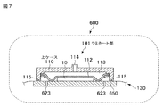
- FIG. 7 is an explanatory view of another example of the laminating apparatus of the present invention.
- FIG. 1 is a cross-sectional view showing a configuration of a solar cell module using a crystal cell as a workpiece 10.
- the solar cell module 10 has a structure in which a plurality of strings 15 are sandwiched between a transparent cover glass 11 and a back material 12 via fillers 13 and 14.
- a material such as polyethylene resin is used for the back material 12.
- the fillers 13 and 14 are made of EVA (ethylene vinyl acetate) resin or the like.
- the string 15 has a configuration in which a plurality of solar cells 18 as crystal cells are connected via lead wires 19.
- the plurality of strings 15 are connected between the electrodes 16 and 17 by lead wires.
- a solar cell module generally called a thin film type can be targeted.
- a power generation element composed of a transparent electrode, a semiconductor, and a back electrode is deposited on a transparent cover glass in advance.
- a cover glass substrate glass
- a filler is placed on the power generating element on the cover glass. Further, the back material is covered on the filler.
- the components of the thin film solar cell module are bonded by vacuum heating lamination in such a state. That is, the thin film solar cell module is merely changed to a power generation element on which the above-described solar cell module crystal cells are deposited.
- the basic sealing structure of the thin film solar cell module is the same as that of the solar cell module described above.
- the laminating apparatus and the laminating method of the present invention can also be applied to a thin-film solar cell module having a structure in which the substrate glass on which the power generating element is deposited is covered with a filler, and further a cover glass is covered thereon.
- the laminating apparatus of the present invention has at least one sub-laminating apparatus (hereinafter abbreviated as sub-machine) in the subsequent process of the main laminating apparatus (hereinafter abbreviated as main machine). ).
- the laminating apparatus used in the main machine and the sub machine will be described with reference to FIG.
- the laminating apparatus LM of the present invention may be configured such that a plurality of sub-machines 400 are arranged separately from the main machine in a subsequent process of the main machine 100.
- the main machine 100 includes an upper case 110, a lower case 120, and a conveyance sheet 130 for conveying the workpiece 10.
- the conveyance sheet 130 conveys the workpiece 10 between the upper case 110 and the lower case 120.
- the main machine 100 is provided with a carry-in conveyor 200 for conveying the workpiece 10 before lamination to the main machine 100.
- the main machine 100 is provided with a connection conveyor 300 for carrying out the laminated workpiece 10 from the main machine 100 and carrying it into the sub machine 400.
- the carry-in conveyor 200 and the connection conveyor 300 are connected to the main machine.
- the workpiece 10 is transferred from the carry-in conveyor 200 to the conveyance sheet 130, and is transferred from the conveyance sheet 130 to the connection conveyor 300.
- the workpiece 10 to be laminated by the auxiliary machine 400 is carried into the auxiliary machine from the connection conveyor 300 and is laminated. After laminating, the workpiece 10 is transferred to the carry-out conveyor 500.
- the connection conveyor 300 and the carry-out conveyor 500 are connected to the auxiliary machine.
- the main machine 100 is provided with a lifting device (not shown) composed of a cylinder, a piston rod, and the like.
- the lifting device can lift and lower the upper case 110 with respect to the lower case 120 while maintaining the horizontal state.
- the elevating device lowers the upper case 110 so that the internal space between the upper case 110 and the lower case 120 can be sealed.
- FIG. 3 is a side sectional view of the laminating unit 101 before laminating the workpiece 10 in the main machine 100.
- FIG. 4 is a cross-sectional side view of the laminating unit 101 during laminating.
- the upper case 110 is formed with a space opened downward.
- a diaphragm 112 as a pressing member is provided so as to partition the space horizontally.
- the diaphragm 112 is formed of heat-resistant rubber such as silicone rubber.
- the diaphragm 112 functions as a pressing member that presses the workpiece 10 and performs lamination.
- a space (upper chamber 113) partitioned by a diaphragm 112 is formed in the upper case 110.
- An intake / exhaust port 114 communicating with the upper chamber 113 is provided on the upper surface of the upper case 110.
- the inside of the upper chamber 113 can be evacuated by a vacuum pump through the intake / exhaust port 114, or the atmosphere can be introduced into the upper chamber 113.
- a space (lower chamber 121) opened upward is formed.
- a hot plate 150 panel-shaped heater
- the heat plate 150 is supported by a support member erected on the bottom surface of the lower case 120 so as to maintain a horizontal state.
- the hot plate 150 is supported so that the surface thereof is substantially level with the opening surface of the lower chamber 121.
- This hot plate 150 uses a sub-machine having a different configuration. This point will be described later.
- An intake / exhaust port 123 communicating with the lower chamber 121 is provided on the lower surface of the lower case 120.
- the inside of the lower chamber 121 can be evacuated by a vacuum pump through the intake / exhaust port 123, and the atmosphere can be introduced into the lower chamber 121.
- a conveying sheet 130 is movably provided between the upper case 110 and the lower case 120 and above the hot plate 150.
- the conveyance sheet 130 receives the workpiece 10 before lamination from the carry-in conveyor 200 in FIG. 2 and accurately conveys it to the central position of the laminating unit 101, that is, the central part of the hot plate 150.
- the conveyance sheet 130 delivers the to-be-processed object 10 after a lamination process by the main machine to the connection conveyor 300 of FIG.
- the hot plate 150 of the main machine and the auxiliary machine is configured as follows.
- the hot plates of the main machine and the sub machine are only different in material and the basic configuration is the same, and thus the same numbers are assigned.
- the heat plate 150 of the main machine is made of a material having a thermal conductivity of 110 (Wm ⁇ 1 K ⁇ 1 ) or more and 398 (Wm ⁇ 1 K ⁇ 1 ) or less in the heat supply portion to the workpiece 10 on the heat plate. Forming.
- the material of the heat supply portion of the hot plate is a material having a thermal conductivity higher than that of the aluminum alloy material.
- the workpiece is quickly heated from the hot plate, and the temperature of the workpiece can reach the target temperature at an early stage.
- the set temperature of the hot plate of the main machine can be set to be equal to or higher than the crosslinking temperature of the filling material in the workpiece, the temperature of the workpiece can be further rapidly increased.
- the entire hot plate 150 may be formed of this material.
- the hot plate 150 of the auxiliary machine is formed of a material having a thermal conductivity of 20 (Wm ⁇ 1 K ⁇ 1 ) or less in a heat supply portion to the workpiece on the hot plate. That is, the heat supply portion of the hot plate is formed of a material having a thermal conductivity equal to or lower than that of stainless steel.
- the temperature of the hot plate is set to the cross-linking temperature of the filler of the workpiece, and the cross-linking reaction of the filler is promoted to perform laminating.
- the entire hot plate 150 may be formed of this material.
- the heat plate used in the main machine and the sub machine of the present embodiment can be configured as shown in FIG. 5 using an electric heater. It is also possible to use a heat pipe in order to make the temperature distribution in the hot plate uniform. As shown in FIG. 5, the hot plate 150 is formed in a panel shape on which the workpiece 10 can be placed using the material described above.
- an accommodation groove 154 is processed in the depth direction.
- a plurality of U-shaped heaters 152 are arranged in parallel in the housing groove 154.
- the heat pipe 153 is provided in parallel with the center of the U-shaped heater 152.
- the heater 152 and the heat pipe 153 are embedded and fixed in the receiving groove 154 by fixing a back plate 156 having substantially the same dimensions as the hot plate main body 151 with a bolt etc. via the cushion material 155.
- the outer periphery of the heater and the outer periphery of the heat pipe are in close contact with the bottom surface of the housing groove 154.
- a plurality of sets of heaters and heat pipes are provided.
- the heater 152 does not have to be U-shaped, and a linear one may be used.
- a known sheath heater SH can be used as the heater.
- the sheath heater SH covers the entire circumference of the nichrome wire SH1 processed in a coil shape at the center, the insulating material SH2 such as magnesium oxide filled around the nichrome wire SH1, and the insulating material SH2. It is comprised from sheath SH3 (outer skin forming the outer periphery).
- a heat pipe having a known configuration can be used as the heat pipe 153.
- the heat pipe is sealed with the working fluid at a saturated vapor pressure in the pipe, and if there is a temperature difference in the length direction of the heat pipe, a steam flow is generated from the hot part to the cold part.
- the hydraulic fluid takes heat of evaporation at the high temperature portion and gives heat of condensation at the low temperature portion.
- the auxiliary machine is arranged at the rear of the main machine.
- the set temperature of the hot plate 150 of the main machine can be set to be equal to or higher than the bridging temperature of the fillers 13 and 14 in the workpiece 10, and the temperature of the workpiece 10 on the hot plate is set.
- the workpiece 10 heated to near the crosslinking temperature is carried into the auxiliary machine and laminated again.
- the temperature of the hot plate of the auxiliary machine is set to the crosslinking temperature.
- the workpiece 10 is pressurized and heated for a certain time by the auxiliary machine, the crosslinking reaction of the filling material is promoted, and the laminating process is completed.
- the laminating method of the present invention the total laminating time is shortened and the production efficiency is greatly improved as compared with the case of laminating by setting the hot plate temperature of the two main machines to the bridging temperature and operating the two simultaneously.
- the laminating process of the main machine according to the present embodiment will be described more specifically. First, as illustrated in FIG. 3, the conveyance sheet 130 conveys the workpiece 10 to the center position of the laminate unit 101. Next, the lifting device lowers the upper case 110.
- the main engine 100 evacuates the inside of the upper chamber 113 with a vacuum pump via the intake / exhaust port 114 of the upper case 110.
- the main machine 100 evacuates the lower chamber 121 with a vacuum pump via the intake / exhaust port 123 of the lower case 120 (hereinafter referred to as a vacuum process).
- the ultimate vacuum in the vacuum process is about the same as that of a normal laminating apparatus, specifically about 130 Pa.
- the main engine 100 introduces the atmosphere into the upper chamber 113 through the intake / exhaust port 114 of the upper case 110 while maintaining the vacuum state of the lower chamber 121.
- a pressure difference is generated between the upper chamber 113 and the lower chamber 121, so that the diaphragm 112 expands. Accordingly, the diaphragm 112 is pushed downward as shown in FIG. 4 (hereinafter referred to as a pressurizing step).
- the workpiece 10 is sandwiched between the diaphragm 112 extruded downward and the hot plate 150.
- the temperature of the hot plate of main machine 100 is set to be equal to or higher than the crosslinking temperature of the filler in workpiece 10 as described in ⁇ 5>. For this reason, the temperature of the workpiece 10 rises early. Further, the constituent members are bonded by the fillers 13 and 14 heated and melted by the clamping pressure. In this way, the main engine 100 introduces air into the lower chamber 121 through the intake / exhaust port 123 of the lower case 120 before the crosslinking reaction is completed. At this time, the lifting device raises the upper case 110. By raising the upper case 110, the conveyance sheet 130 can be moved as shown in FIG.
- the conveyance sheet 130 delivers the workpiece 10 after lamination to the connection conveyor 300.
- the laminating process of the auxiliary machine 400 will be described more specifically.
- the workpiece 10 laminated by the main machine on the connection conveyor 300 is conveyed to the center position of the laminating unit 101 by the conveyance sheet 130 of the auxiliary machine.
- the state is the same as in FIG.
- the lifting device lowers the upper case 110.
- the internal space between the upper case 110 and the lower case 120 is sealed as shown in FIG. That is, the upper chamber 113 and the lower chamber 121 can be kept sealed inside the upper case 110 and the lower case 120, respectively.
- the auxiliary machine 400 evacuates the inside of the upper chamber 113 with a vacuum pump through the intake / exhaust port 114 of the upper case 110. Similarly, the auxiliary machine 400 evacuates the lower chamber 121 with a vacuum pump through the intake / exhaust port 123 of the lower case 120 (hereinafter referred to as a vacuum process).
- the ultimate vacuum in the vacuum process of the secondary machine is because the bubbles in the workpiece have already been sent to the outside.
- the ultimate vacuum may not be as small as the main machine. It can be set as appropriate according to the characteristics of the workpiece.
- the workpiece 10 is heated by the hot plate 150 heated by the temperature control CL (see FIG. 5) of the temperature control device.
- the fillers 13 and 14 (already in a molten state) contained in the workpiece 10 are also heated.
- the auxiliary machine 400 introduces the atmosphere into the upper chamber 113 through the intake / exhaust port 114 of the upper case 110 while maintaining the vacuum state of the lower chamber 121.
- a pressure difference is generated between the upper chamber 113 and the lower chamber 121, so that the diaphragm 112 expands.
- the diaphragm 112 is pushed downward as shown in FIG. 4 (hereinafter referred to as a pressurizing step).
- the workpiece 10 is sandwiched between the diaphragm 112 extruded downward and the hot plate 150.
- the temperature of the hot plate of the auxiliary machine 400 is set to the bridging temperature of the fillers 13 and 14 contained in the workpiece 10 as described in ⁇ 5>.
- the temperature of the filler in 10 is maintained at the crosslinking temperature for a certain time.
- the crosslinking reaction of the filler is promoted, a laminate having a target crosslinking density is completed, and the lamination process is completed.
- the auxiliary machine 400 introduces the atmosphere into the lower chamber 121 through the intake / exhaust port 123 of the lower case 120.
- the lifting device raises the upper case 110. By raising the upper case 110, the conveyance sheet 130 can be moved as shown in FIG.
- the conveyance sheet 130 delivers the workpiece 10 after lamination to the carry-out conveyor 500.
- the laminating apparatus of this embodiment may be used for the main machine and the sub machine, or may be used for either the main machine or the sub machine.
- the laminating apparatus 600 of the present embodiment has an upper case 110, and the lower case is configured to also serve as a hot plate 650.
- the workpiece 10 is placed at a predetermined position on the hot plate 650 by the conveyance sheet 130 traveling on the hot plate 650.
- the contents of the laminating process are the same as described in ⁇ 5> to ⁇ 7>.
- the vacuum process is performed by the intake / exhaust port 114 of the upper case and through-holes 623 for intake / exhaust in the downward direction provided in appropriate positions on the heat plate.
- the pressurizing step is performed by the diaphragm 112 which is a pressing member.
Abstract
Description
ラミネート加工は、太陽電池モジュールを製造する工程の中でも長時間の加工時間を要する工程である。したがって、必要な太陽電池モジュールの製造数量を確保するために、ラミネート加工時間を短縮することが課題となっている。
しかしながら,これら特許文献1から特許文献3に記載のラミネート装置は,太陽電池モジュールを効率良く大量にラミネート加工することが困難であった。このような問題を解決するために特許文献4に記載のとおりラミネート装置を隣接して2台並設したものが開示されている。
特許文献4に記載のラミネート装置では、ラミネート装置を2台並設しているので搬入コンベアの設置スペースが節約される効果はあるものの、ラミネート加工時間は、ラミネート装置を2台分使用した場合と同程度の短縮であり、それ以上の時間短縮は十分ではなかった。
Lamination is a process that requires a long processing time in the process of manufacturing a solar cell module. Therefore, in order to secure the required production quantity of solar cell modules, it is an issue to shorten the laminating time.
However, these laminating apparatuses described in
In the laminating apparatus described in Patent Document 4, since two laminating apparatuses are arranged side by side, the installation space for the carry-in conveyor is saved, but the laminating time is the same as when two laminating apparatuses are used. It was a similar reduction, and further time reduction was not enough.
第1発明によれば、メインラミネート装置の熱板の給熱部分に熱伝率の高い素材を使用して形成しているので、熱板の温度を従来よりも高い温度に短時間で昇温させることができるとともに、被加工物の温度を短時間で所定温度に昇温することができる。したがってメインラミネート装置の熱板温度をサブラミネート装置の熱板温度よりも高くすることにより、メインラミネート装置とサブラミネート装置を組み合わせ使用することにより、単にラミネート装置を2台併設した場合に比ベラミネート加工時間を短縮することができる。
第2発明のラミネート装置は、第1発明において、前記メインラミネート装置は、押圧部材を備えた上ケースと、熱板を有し、その前記熱板上に被加工物を載置し、上ケースと熱板を閉合し、前記熱板により加熱した前記被加工物を、前記押圧部材により仕切られた下チャンバを真空とし前記上チャンバに大気を導入し前記熱板と前記押圧部材とで挟圧してラミネートすることを特徴とする。
第2発明は、従来のラミネート装置で使用していた下ケースを廃止し、熱板としたものである。その熱板を第1発明のものを使用している。従って第1発明の効果以外に、装置の構造は非常に簡略化され安価となるという効果が発現する。
第3発明のラミネート装置は、第1発明において、前記メインラミネート装置及び前記サブラミネート装置は、押圧部材を備えた上ケースと、熱板を有し、その前記熱板上に被加工物を載置し、上ケースと熱板を閉合し、前記熱板により加熱した前記被加工物を、前記押圧部材により仕切られた下チャンバを真空とし前記上チャンバに大気を導入し前記熱板と前記押圧部材とで挟圧してラミネートすることを特徴とする。
第3発明によれば、第2発明と同様の効果が発現する。
第4発明のラミネート装置は、第1発明において、前記メインラミネート装置は、押圧部材を備えた上ケースと、熱板を備えた下ケースとを有し、その前記熱板上に被加工物を載置し、上ケースと下ケースとを閉合し、前記熱板により加熱した前記被加工物を、前記押圧部材により仕切られた下チャンバを真空とし前記上チャンバに大気を導入し前記熱板と前記押圧部材とで挟圧してラミネートすることを特徴とする。
第4発明によれば、第1発明と同様の効果が発現する。
第5発明のラミネート装置は、第1発明において、前記メインラミネート装置及び前記サブラミネート装置は、押圧部材を備えた上ケースと、熱板を備えた下ケースとを有し、その前記熱板上に被加工物を載置し、上ケースと下ケースとを閉合し、前記熱板により加熱した前記被加工物を、前記押圧部材により仕切られた下チャンバを真空とし前記上チャンバに大気を導入し前記熱板と前記押圧部材とで挟圧してラミネートすることを特徴とする。
第5発明によれば、第1発明と同様の効果が発現する。
第6発明のラミネート装置は、第1発明から第5発明のいずれかいにおいて、 前記メインラミネート装置及び前記サブラミネート装置のいずれかの熱板に電気式ヒータを埋設したことを特徴とする。
第6発明によれば、熱板に電気式ヒータを使用しているので、従来の油加熱式に比べ短時間で熱板の温度を上昇させることができる。このため第1発明の効果を顕著に発現することができる。 A laminating apparatus according to a first invention for achieving the object of the present invention is a laminating apparatus comprising a main laminating apparatus, and comprising at least one sub-laminating apparatus in a subsequent process of the main laminating apparatus, The heating plate of the laminating apparatus is formed with a material having a thermal conductivity of 110 (Wm −1 K −1 ) or more and 398 (Wm −1 K −1 ) or less in the heat supply portion to the workpiece on the heating plate. The heating plate of the sublaminating apparatus is characterized in that the heat supply portion to the workpiece on the heating plate is formed of a material having a thermal conductivity of 20 (Wm −1 K −1 ) or less.
According to the first aspect of the present invention, since the heat supply portion of the hot plate of the main laminating apparatus is formed using a material having a high thermal conductivity, the temperature of the hot plate is raised to a higher temperature than before in a short time. In addition, the temperature of the workpiece can be raised to a predetermined temperature in a short time. Therefore, by making the hot plate temperature of the main laminating device higher than the hot plate temperature of the sub-laminating device, the main laminating device and the sub-laminating device are used in combination, so that the laminating device can be laminated more than when two laminating devices are installed together. Processing time can be shortened.
A laminating apparatus according to a second invention is the laminating apparatus according to the first invention, wherein the main laminating apparatus has an upper case provided with a pressing member and a hot plate, and a workpiece is placed on the hot plate, and the upper case The work plate heated by the hot plate is closed and the lower chamber partitioned by the pressing member is evacuated to introduce the atmosphere into the upper chamber and sandwiched between the hot plate and the pressing member. And laminating.
In the second invention, the lower case used in the conventional laminating apparatus is abolished and used as a hot plate. The hot plate of the first invention is used. Therefore, in addition to the effects of the first invention, the structure of the apparatus is greatly simplified and inexpensive.
A laminating apparatus according to a third invention is the laminating apparatus according to the first invention, wherein the main laminating apparatus and the sub-laminating apparatus have an upper case provided with a pressing member and a hot plate, and a workpiece is placed on the hot plate. The upper case and the hot plate are closed, and the workpiece heated by the hot plate is evacuated to the lower chamber partitioned by the pressing member, and air is introduced into the upper chamber to press the hot plate and the hot plate. It is characterized by laminating by pressing with a member.
According to the third aspect, the same effect as in the second aspect is exhibited.
According to a fourth aspect of the present invention, there is provided a laminating apparatus according to the first aspect, wherein the main laminating apparatus has an upper case having a pressing member and a lower case having a hot plate, and a workpiece is placed on the hot plate. The upper case and the lower case are placed, the workpiece heated by the hot plate is vacuumed in the lower chamber partitioned by the pressing member, and the atmosphere is introduced into the upper chamber and the hot plate It is characterized by laminating by pressing with the pressing member.
According to the 4th invention, the same effect as the 1st invention appears.
A laminating apparatus according to a fifth aspect of the present invention is the laminating apparatus according to the first aspect, wherein the main laminating apparatus and the sub-laminating apparatus have an upper case having a pressing member and a lower case having a hot plate. The workpiece is placed on the upper case, the upper case and the lower case are closed, and the workpiece heated by the hot plate is evacuated into the lower chamber partitioned by the pressing member, and the atmosphere is introduced into the upper chamber. And it laminates by pinching with the said hot plate and the said press member.
According to the fifth aspect, the same effect as in the first aspect is exhibited.
According to a sixth aspect of the present invention, there is provided a laminating apparatus according to any one of the first to fifth aspects, wherein an electric heater is embedded in one of the hot plates of the main laminating apparatus and the sublaminating apparatus.
According to the sixth aspect, since the electric heater is used for the hot plate, the temperature of the hot plate can be raised in a shorter time than the conventional oil heating type. For this reason, the effect of 1st invention can be expressed notably.
図2は、本発明のラミネート装置の説明図。
図3は、本発明のラミネート装置のラミネート加工部の説明図。
図4は、本発明のラミネート装置のラミネート加工部の説明図。
図5は、本発明のラミネート装置用の熱板の説明図。
図6は、本発明のラミネート装置用の熱板用のシースヒータの説明図。
図7は、本発明の別例のラミネート装置の説明図。 FIG. 1 is an explanatory view of a solar cell module targeted by the laminating apparatus of the present invention.
FIG. 2 is an explanatory diagram of the laminating apparatus of the present invention.
FIG. 3 is an explanatory view of a laminating portion of the laminating apparatus of the present invention.
FIG. 4 is an explanatory view of a laminating portion of the laminating apparatus of the present invention.
FIG. 5 is an explanatory view of a hot plate for the laminating apparatus of the present invention.
FIG. 6 is an explanatory view of a sheath heater for a hot plate for the laminating apparatus of the present invention.
FIG. 7 is an explanatory view of another example of the laminating apparatus of the present invention.
13 充填材
14 充填材
100 ラミネート装置(主機)
101 ラミネート部
110 上ケース
120 下ケース
150 熱板
130 搬送シート
200 搬入コンベア
300 接続コンベア
400 ラミネート装置(副機)
500 搬出コンベア
600 別例のラミネート装置
650 熱板
LM 本発明のラミネート装置 10 Workpiece (solar cell)
13 Filler 14
DESCRIPTION OF SYMBOLS 101 Laminating
500 Unloading
<1>被加工物(太陽電池モジュール)
ここで本発明のラミネート装置でラミネートされる被加工物10について説明する。
図1は、被加工物10として結晶系セルを使用した太陽電池モジュールの構成を示す断面図である。太陽電池モジュール10は、図示のように、透明なカバーガラス11と裏面材12との間に、充填材13、14を介して複数列のストリング15を挟み込んだ構成を有する。裏面材12にはポリエチレン樹脂等の材料が使用される。また、充填材13、14にはEVA(エチレンビニルアセテート)樹脂等が使用される。ストリング15は、結晶系セルとしての太陽電池セル18を複数枚リード線19を介して接続した構成である。この複数列のストリング15は、電極16、17の間でリード線により接続されている。
また、被加工物10としては、上述した太陽電池モジュールだけではなく、一般に薄膜式と呼ばれる太陽電池モジュールを対象とすることもできる。この薄膜式太陽電池モジュールの代表的な構造例では、透明なカバーガラスに、予め、透明電極、半導体、裏面電極からなる発電素子が蒸着してある。このような薄膜式太陽電池モジュールは、カバーガラス(基板ガラス)を下向きに配置し、カバーガラス上の発電素子の上に充填材を被せる。更に、充填材の上に裏面材を被せた構造になっている。このような状態で真空加熱ラミネートすることにより薄膜式太陽電池モジュールの構成部材が接着される。すなわち、薄膜式太陽電池モジュールは、上述した太陽電池モジュールの結晶系セルが蒸着された発電素子に変わるだけである。薄膜式太陽電池モジュールの基本的な封止構造は上述した太陽電池モジュールと同じである。
尚本発明のラミネート装置及びラミネート方法は、上記の発電素子を蒸着した基板ガラスに充填材を被せ、さらにその上にカバーガラスを被せた構成の薄膜式太陽電池モジュールにも適用することができる。
<2>本発明のラミネート装置の概略構成の説明
本発明のラミネート装置は、メインラミネート装置(以下、主機と略称する)の後工程に少なくとも1台のサブラミネート装置(以下、副機と略称する)を設置した構成である。主機と副機にて使用するラミネート装置については、図2を使用して説明する。
本発明のラミネート装置LMは、主機100の後工程に主機と離して別置として副機400を複数台配置する構成とすることも可能である。本実施形態の説明においては、図2のように主機の後部に副機を1台、コンベア等で接続した形態にて説明する。
主機及び副機の構成は、それぞれ別構成(別形態)のものを使用することもできる。しかし本実施形態の説明においては、同一形態のものを使用する場合で説明する。熱板以外は同一であるので、主機の構成について説明する。主機100は、上ケース110と、下ケース120と、被加工物10を搬送するための搬送シート130とを有する。搬送シート130は、被加工物10を上ケース110と下ケース120との間に搬送する。主機100には、ラミネート前の被加工物10を主機100に搬送するための搬入コンベア200が設けられている。また、主機100には、ラミネート後の被加工物10を主機100から搬出し、副機400へ搬入するための接続コンベア300が設けられている。搬入コンベア200と接続コンベア300とは、主機に連接されている。被加工物10は、搬入コンベア200から搬送シート130に受け渡され、搬送シート130から接続コンベア300に受け渡される。
副機400にてラミネ−ト加工するための被加工物10は接続コンベア300から副機に搬入され、ラミネート加工を行う。ラミネート加工後、被加工物10は搬出コンベア500に受け渡さされる。接続コンベア300と搬出コンベア500とは、副機に連接されている。
主機100には、シリンダ及びピストンロッド等で構成される図示しない昇降装置が設けられている。昇降装置は、上ケース110を水平状態に維持したまま下ケース120に対して昇降させることができる。昇降装置が上ケース110を下降させることで、上ケース110と下ケース120との内部空間を密閉させることができる。
<3>ラミネート部
次に、本実施形態に係る主機100のラミネート部101の構成についてより具体的に説明する。副機のラミネート部の構成は同一であるので<2>と同様、主機についてのみ説明する。図3は、主機100において被加工物10をラミネート加工する前のラミネート部101の側断面図である。図4は、ラミネート加工時におけるラミネート部101の側断面図である。
上ケース110には、下方向に開口された空間が形成されている。この空間には、空間を水平に仕切るように押圧部材としてのダイヤフラム112が設けられている。ダイヤフラム112は、シリコーン系のゴム等の耐熱性のあるゴムにより成形されている。後述するように、ダイヤフラム112は、被加工物10を押圧する押圧部材として機能し、ラミネートを行う。上ケース110内には、ダイヤフラム112によって仕切られた空間(上チャンバ113)が形成される。
また、上ケース110の上面には、上チャンバ113と連通する吸排気口114が設けられている。上チャンバ113では、吸排気口114を介して、上チャンバ113内を真空ポンプにより真空引きして真空状態にしたり、上チャンバ113内に大気を導入したりすることができる。
下ケース120には、上方向に開口された空間(下チャンバ121)が形成されている。この空間には、熱板150(パネル状のヒータ)が設けられている。熱板150は、下ケース120の底面に立設された支持部材によって、水平状態を保つように支持されている。この場合に、熱板150は、その表面が下チャンバ121の開口面とほぼ同一高さになるように支持される。この熱板150は、副機は異なる構成のものを使用する。この点については後述する。
また、下ケース120の下面には、下チャンバ121と連通する吸排気口123が設けられている。下チャンバ121では、吸排気口123を介して、下チャンバ121内を真空ポンプにより真空引きして真空状態にしたり、下チャンバ121内に大気を導入したりすることができる。
上ケース110と下ケース120との間であって、熱板150の上方には、搬送シート130が移動自在に設けられている。搬送シート130は、図2の搬入コンベア200からラミネート前の被加工物10を受け取ってラミネート部101の中央位置、すなわち熱板150の中央部に正確に搬送する。また、搬送シート130は、主機にてラミネート加工後の被加工物10を図2の接続コンベア300に受け渡す。
<4>熱板の構成
本実施形態では、主機と副機の熱板150を以下のように構成している。本実施形態の説明では、主機と副機の熱板は材質のみの違いであり基本的な構成は同じであるため、同一番号を付している。
主機の熱板150は、その熱板上の被加工物10への給熱部を熱伝導率が110(Wm−1K−1)以上、398(Wm−1K−1)以下の材料で形成している。すなわち主機では、ラミネート加工する被加工物10の温度上昇を早めるために熱板の給熱部の素材をアルミニウム合金材の熱伝導率以上の素材を使用している。これにより熱板から被加工物へ迅速に給熱され、被加工物の温度を目標温度に早期に到達させることができる。また主機の熱板の設定温度を被加工物内の充填材料の架橋温度以上とすることができるので、更に被加工物の温度を迅速に上昇させることができる。また熱板150全体を本素材にて形成することでも良い。
一方副機の熱板150は、熱板上の被加工物への給熱部を熱伝導率が20(Wm−1K−1)以下の材料で形成している。すなわちステンレス材等の熱伝導率以下の素材にて熱板の供熱部を形成している。副機においては、熱板の温度を被加工物の充填材の架橋温度に設定し充填材の架橋反応を促進させラミネート加工を行う。このためアルミニウム合金のように熱伝導率が良好ということよりも、熱伝導率は小さくとも、熱容量(比熱×密度)の大きな材料を使用し温度変化を無くし安定的に保持することが必要である。このためステンレス材のような材料が好ましい。また主機と同じように、熱板150全体を本素材にて形成することでも良い。
本実形態の主機及び副機に使用する熱板は、一例として電気式ヒータを使用し図5に示すように構成することができる。また熱板内の温度分布を一様にするためにヒートパイプを併用することも可能である。
熱板150は、図5に示すように、上記で説明した素材により、被加工物10を載置できるようなパネル状に形成されている。熱板本体151には、ヒータ152およびヒートパイプ153を埋設するために、奥行き方向に収容溝154が加工されている。この収容溝154にU字状のヒータ152が平行に複数配設されている。ヒートパイプ153は、U字状のヒータ152の中央に平行に設けられている。ヒータ152とヒートパイプ153は、クッション材155を介して熱板本体151と略同一寸法の裏板156を熱板本体151とボルト等により固定し収容溝154内に埋設固定される。これによりヒータの外周、およびヒートパイプの外周が収容溝154の底面と密着する。このようにヒータとヒートパイプが複数組設けられている。尚ヒータ152は、U字状でなくても良く、直線状のものを使用することでも良い。
ここでは、ヒータとしては、公知のシースヒータSHを使用することができる。シースヒータSHは、図6に示すように、中心にコイル状に加工されたニクロム線SH1と、ニクロム線SH1の周りに充填された酸化マグネシウム等の絶縁材SH2と、絶縁材SH2の全周を覆うシースSH3(外周をなす外皮)から構成される。
ヒートパイプ153は,公知の構成のものを使用することができる。ヒートパイプは、管内に作動液が飽和蒸気圧の状態で密封されていて、ヒートパイプの長さ方向に温度差があると高温部から低温部に蒸気流が発生します。そして作動液は、高温部で蒸発熱を奪い、低温部では凝縮熱を与えることになる。
<5>本発明のラミネート方法
主機及び副機のラミネート加工の詳細は、<6>にて説明するが、ラミネート加工時間の短縮はラミネート加工中の被加工物の加熱時間をいかに短くするかに依存している。このため熱板の温度を高く設定すると昇温時間は短縮され、加熱時間も短縮される。しかしながら主機を1台のみでラミネート加工する場合は、熱板の設定温度を充填材の架橋温度以上に設定することは困難である。
そこで本発明のラミネート方法では、図2に示すように、主機の後部に副機を配置する構成としている。このような構成とすることにより主機の熱板150の設定温度を被加工物10内の充填材13、14の架橋温度以上に設定することが可能となり、熱板上の被加工物10の温度を架橋温度付近に迅速に加熱することが可能である。架橋温度付近に加熱された被加工物10は、副機に搬入され、再度ラミネート加工される。副機の熱板は、その温度は架橋温度に設定されている。被加工物10は、副機で一定時間加圧加熱され充填材料の架橋反応が促進されてラミネート加工が終了する。
本発明のラミネート方法によれば、2台の主機の熱板温度を架橋温度に設定して2台同時に運転してラミネート加工する場合に比べ合計のラミネート加工時間が短縮され生産効率が大幅に向上する。
<6>主機のラミネート工程の説明
次に、本実施形態に係る主機のラミネート工程についてより具体的に説明する。まず、図3に示すように、搬送シート130は、被加工物10をラミネート部101の中央位置に搬送する。
次に、昇降装置は、上ケース110を下降させる。上ケース110を下降させることにより、図4に示すように、上ケース110と下ケース120との内部空間は、密閉される。すなわち、上ケース110と下ケース120との内部にて上チャンバ113及び下チャンバ121は、それぞれ密閉状態に保つことができる。
次に、主機100は、上ケース110の吸排気口114を介して、上チャンバ113内を真空ポンプにより真空引きを行う。同様に、主機100は、下ケース120の吸排気口123を介して、下チャンバ121内を真空ポンプにより真空引きを行う(以下真空工程という)。真空工程の到達真空度は、通常のラミネート装置と同程度であり、具体的には約130Pa程度である。下チャンバ121の真空引きにより、被加工物10内に含まれている気泡やガスは、被加工物10外に送出される。
被加工物10は、温度制御装置CL(図5参照)の温度制御により加熱された熱板150によって加熱されるので、被加工物10の内部に含まれる充填材13、14も加熱される。
次に、主機100は、下チャンバ121の真空状態を保ったまま、上ケース110の吸排気口114を介して、上チャンバ113に大気を導入する。これにより、上チャンバ113と下チャンバ121との間に気圧差が生じることで、ダイヤフラム112が膨張する。従って、ダイヤフラム112は、図4に示すように下方に押し出される(以下加圧工程という)。被加工物10は、下方に押し出されたダイヤフラム112と、熱板150とで挟圧される。この挟圧とともに、主機100の熱板の温度は、<5>にて説明のとおり、被加工物10内の充填材の架橋温度以上に設定されている。このため被加工物10は、早期に温度上昇する。また挟圧により、加熱溶融された充填材13、14によって各構成部材が接着される。
このようにして架橋反応が完了する一定時間前に、主機100は、下ケース120の吸排気口123を介して、下チャンバ121に大気を導入する。このとき、昇降装置は、上ケース110を上昇させる。上ケース110を上昇させることにより、図3に示すように、搬送シート130を移動させることができるようになる。搬送シート130は、ラミネート後の被加工物10を接続コンベア300に受け渡す。
<7>副機のラミネート工程の説明
次に、本実施形態に係る副機400のラミネート工程についてより具体的に説明する。まず、接続コンベア300上の主機でラミネート加工した被加工物10を副機の搬送シート130により、ラミネート部101の中央位置に搬送する。図3と同じような状態とする。
次に、昇降装置は、上ケース110を下降させる。上ケース110を下降させることにより、図4に示すように、上ケース110と下ケース120との内部空間は、密閉される。すなわち、上ケース110と下ケース120との内部にて上チャンバ113及び下チャンバ121は、それぞれ密閉状態に保つことができる。
次に、副機400は、上ケース110の吸排気口114を介して、上チャンバ113内を真空ポンプにより真空引きを行う。同様に、副機400は、下ケース120の吸排気口123を介して、下チャンバ121内を真空ポンプにより真空引きを行う(以下真空工程という)。副機の真空工程の到達真空度は、既に被加工物内の気泡が外部に送出されているので。主機ほど到達真空度は小さくなくても良い。被加工物の特性に応じて適宜設定することができる。
被加工物10は、温度制御装置の温度制御CL(図5参照)により加熱された熱板150によって加熱される。主機同様、被加工物10の内部に含まれる充填材13、14(既に溶融状態である)も加熱される。
次に、副機400は、下チャンバ121の真空状態を保ったまま、上ケース110の吸排気口114を介して、上チャンバ113に大気を導入する。これにより、上チャンバ113と下チャンバ121との間に気圧差が生じることで、ダイヤフラム112が膨張する。従って、ダイヤフラム112は、図4に示すように下方に押し出される(以下加圧工程という)。被加工物10は、下方に押し出されたダイヤフラム112と、熱板150とで挟圧される。この挟圧とともに、副機400の熱板の温度は、<5>にて説明のとおり、被加工物10の内部に含まれる充填材13、14は架橋温度に設定されており、被加工物10内の充填材等の温度は架橋温度に一定時間保持される。これにより充填材の架橋反応が促進し、目標となる架橋密度を有するラミネート体が完成しラミネート加工が終了する。
このように被加工物10のラミネート加工が終了した後に、副機400は、下ケース120の吸排気口123を介して、下チャンバ121に大気を導入する。このとき、昇降装置は、上ケース110を上昇させる。上ケース110を上昇させることにより、図3に示すように、搬送シート130を移動させることができるようになる。搬送シート130は、ラミネート後の被加工物10を搬出コンベア500に受け渡す。
<8>本発明の別例のラミネート装置
図7により本発明の別例のラミネート装置の実施形態について説明する。本実施形態のラミネート装置を主機及び副機に使用しても良いし、主機または副機のいずれか一方に使用しても良い。尚説明において図3のラミネート装置と同様の機能及び構造を有する部位には同一番号を付している。
図7に示すように、本実施形態のラミネート装置600は、上ケース110を有し、下ケースは熱板650と兼用する構成である。被加工物10は熱板650上を走行する搬送シート130により熱板650上の所定位置に載置される。ラミネート加工の内容は<5>から<7>の記載と同様である。真空工程は、上ケースの吸排気口114と熱板に適宜の数箇所設けられた下方への吸排気用の貫通孔623により行われる。また加圧工程は、押圧部材であるダイヤフラム112により行われる。
ラミネート装置を本実施形態のような構成とすることにより、<5>で記載したラミネート加工時間が短縮され生産効率が大幅に向上するという効果が得られるとともに装置の構成が大幅に簡略化され装置のコストを安価とすることができる。
以上、本発明の実施形態について説明したが、本発明は上記実施形態に限定されるものではなく、種々の変形実施が当業者にとって可能であるのは勿論である。 Embodiments of the present invention will be described with reference to the drawings.
<1> Workpiece (solar cell module)
Here, the
FIG. 1 is a cross-sectional view showing a configuration of a solar cell module using a crystal cell as a
Moreover, as the
The laminating apparatus and the laminating method of the present invention can also be applied to a thin-film solar cell module having a structure in which the substrate glass on which the power generating element is deposited is covered with a filler, and further a cover glass is covered thereon.
<2> Description of Schematic Configuration of Laminating Apparatus of the Present Invention The laminating apparatus of the present invention has at least one sub-laminating apparatus (hereinafter abbreviated as sub-machine) in the subsequent process of the main laminating apparatus (hereinafter abbreviated as main machine). ). The laminating apparatus used in the main machine and the sub machine will be described with reference to FIG.
The laminating apparatus LM of the present invention may be configured such that a plurality of
Different configurations (different forms) may be used for the main unit and the sub unit. However, in the description of this embodiment, the case where the same form is used will be described. Since the components other than the hot plate are the same, the configuration of the main machine will be described. The
The
The
<3> Laminating Unit Next, the configuration of the laminating unit 101 of the
The
An intake /
In the
An intake /
A conveying
<4> Configuration of Hot Plate In the present embodiment, the
The
On the other hand, the
As an example, the heat plate used in the main machine and the sub machine of the present embodiment can be configured as shown in FIG. 5 using an electric heater. It is also possible to use a heat pipe in order to make the temperature distribution in the hot plate uniform.
As shown in FIG. 5, the
Here, a known sheath heater SH can be used as the heater. As shown in FIG. 6, the sheath heater SH covers the entire circumference of the nichrome wire SH1 processed in a coil shape at the center, the insulating material SH2 such as magnesium oxide filled around the nichrome wire SH1, and the insulating material SH2. It is comprised from sheath SH3 (outer skin forming the outer periphery).
A heat pipe having a known configuration can be used as the
<5> Laminating method of the present invention The details of the laminating process of the main machine and the submachine will be described in <6>. How to shorten the laminating time is how to shorten the heating time of the workpiece during laminating. It depends. For this reason, when the temperature of the hot plate is set high, the heating time is shortened and the heating time is also shortened. However, when laminating with only one main machine, it is difficult to set the set temperature of the hot plate above the crosslinking temperature of the filler.
Therefore, in the laminating method of the present invention, as shown in FIG. 2, the auxiliary machine is arranged at the rear of the main machine. With such a configuration, the set temperature of the
According to the laminating method of the present invention, the total laminating time is shortened and the production efficiency is greatly improved as compared with the case of laminating by setting the hot plate temperature of the two main machines to the bridging temperature and operating the two simultaneously. To do.
<6> Description of Laminating Process of Main Machine Next, the laminating process of the main machine according to the present embodiment will be described more specifically. First, as illustrated in FIG. 3, the
Next, the lifting device lowers the
Next, the
Since the
Next, the
In this way, the
<7> Explanation of Laminating Process of Submachine Next, the laminating process of the
Next, the lifting device lowers the
Next, the
The
Next, the
Thus, after the laminating process of the
<8> Another Laminating Apparatus of the Present Invention An embodiment of another laminating apparatus of the present invention will be described with reference to FIG. The laminating apparatus of this embodiment may be used for the main machine and the sub machine, or may be used for either the main machine or the sub machine. In the description, parts having the same functions and structures as those of the laminating apparatus in FIG.
As shown in FIG. 7, the
By configuring the laminating apparatus as in the present embodiment, an effect that the laminating time described in <5> is shortened and production efficiency is greatly improved is obtained, and the apparatus configuration is greatly simplified. The cost can be reduced.
Although the embodiments of the present invention have been described above, the present invention is not limited to the above-described embodiments, and various modifications can be made by those skilled in the art.
Claims (6)
- メインラミネート装置を備え、前記メインラミネート装置の後工程に、少なくとも一台のサブラミネート装置を備えたラミネート装置であって、
前記メインラミネート装置の熱板を、熱板上の被加工物への給熱部を熱伝導率が110(Wm−1K−1)以上、398(Wm−1K−1)以下の材料で形成し、
前記サブラミネート装置の熱板を、熱板上の被加工物への給熱部を熱伝導率が20(Wm−1K−1)以下の材料で形成した
ことを特徴とするラミネート装置。 A laminating apparatus comprising a main laminating apparatus, and having at least one sub-laminating apparatus in a subsequent process of the main laminating apparatus,
The heating plate of the main laminating apparatus, the heat supply portion to the workpiece on the heating plate, the material having a thermal conductivity of 110 (Wm −1 K −1 ) or more and 398 (Wm −1 K −1 ) or less. Forming,
A laminating apparatus, wherein the heat plate of the sub-laminating apparatus is formed of a material having a thermal conductivity of 20 (Wm −1 K −1 ) or less in a heat supply portion to a workpiece on the hot plate. - 前記メインラミネート装置は、押圧部材を備えた上ケースと、熱板を有し、
その前記熱板上に被加工物を載置し、上ケースと熱板を閉合し、前記熱板により加熱した前記被加工物を、前記押圧部材により仕切られた下チャンバを真空とし前記上チャンバに大気を導入し前記熱板と前記押圧部材とで挟圧してラミネートすること
を特徴とする請求項1に記載のラミネート装置。 The main laminating apparatus has an upper case provided with a pressing member, and a heat plate,
The workpiece is placed on the hot plate, the upper case and the hot plate are closed, and the workpiece heated by the hot plate is vacuumed in the lower chamber partitioned by the pressing member. The laminating apparatus according to claim 1, wherein air is introduced into the substrate and sandwiched between the hot plate and the pressing member for lamination. - 前記メインラミネート装置及び前記サブラミネート装置は、押圧部材を備えた上ケースと、熱板を有し、
その前記熱板上に被加工物を載置し、上ケースと熱板を閉合し、前記熱板により加熱した前記被加工物を、前記押圧部材により仕切られた下チャンバを真空とし前記上チャンバに大気を導入し前記熱板と前記押圧部材とで挟圧してラミネートすること
を特徴とする請求項1に記載のラミネート装置。 The main laminating apparatus and the sub laminating apparatus have an upper case provided with a pressing member, and a heat plate,
The workpiece is placed on the hot plate, the upper case and the hot plate are closed, and the workpiece heated by the hot plate is vacuumed in the lower chamber partitioned by the pressing member. The laminating apparatus according to claim 1, wherein air is introduced into the substrate and sandwiched between the hot plate and the pressing member for lamination. - 前記メインラミネート装置は、押圧部材を備えた上ケースと、熱板を備えた下ケースとを有し、
その前記熱板上に被加工物を載置し、上ケースと下ケースとを閉合し、前記熱板により加熱した前記被加工物を、前記押圧部材により仕切られた下チャンバを真空とし前記上チャンバに大気を導入し前記熱板と前記押圧部材とで挟圧してラミネートすること
を特徴とする請求項1に記載のラミネート装置。 The main laminating apparatus has an upper case provided with a pressing member, and a lower case provided with a hot plate,
The workpiece is placed on the hot plate, the upper case and the lower case are closed, and the workpiece heated by the hot plate is vacuumed in the lower chamber partitioned by the pressing member. The laminating apparatus according to claim 1, wherein air is introduced into a chamber and laminating is performed by pressing between the hot plate and the pressing member. - 前記メインラミネート装置及び前記サブラミネート装置は、押圧部材を備えた上ケースと、熱板を備えた下ケースとを有し、
その前記熱板上に被加工物を載置し、上ケースと下ケースとを閉合し、前記熱板により加熱した前記被加工物を、前記押圧部材により仕切られた下チャンバを真空とし前記上チャンバに大気を導入し前記熱板と前記押圧部材とで挟圧してラミネートすること
を特徴とする請求項1に記載のラミネート装置。 The main laminating apparatus and the sub laminating apparatus have an upper case provided with a pressing member and a lower case provided with a hot plate,
The workpiece is placed on the hot plate, the upper case and the lower case are closed, and the workpiece heated by the hot plate is vacuumed in the lower chamber partitioned by the pressing member. The laminating apparatus according to claim 1, wherein air is introduced into a chamber and laminating is performed by pressing between the hot plate and the pressing member. - 前記メインラミネート装置及び前記サブラミネート装置のいずれかの熱板に電気式ヒータを埋設したことを特徴とする請求項1から請求項5のいずれかに記載のラミネート装置。 The laminating apparatus according to any one of claims 1 to 5, wherein an electric heater is embedded in a hot plate of either the main laminating apparatus or the sub-laminating apparatus.
Priority Applications (3)
| Application Number | Priority Date | Filing Date | Title |
|---|---|---|---|
| KR1020147029777A KR20140139583A (en) | 2012-03-28 | 2013-03-28 | Laminate device |
| CN201380016623.1A CN104203545A (en) | 2012-03-28 | 2013-03-28 | Laminating device |
| US14/387,840 US20150034250A1 (en) | 2012-03-28 | 2013-03-28 | Laminating apparatus |
Applications Claiming Priority (2)
| Application Number | Priority Date | Filing Date | Title |
|---|---|---|---|
| JP2012073271A JP5922461B2 (en) | 2012-03-28 | 2012-03-28 | Laminating equipment |
| JP2012-073271 | 2012-03-28 |
Publications (1)
| Publication Number | Publication Date |
|---|---|
| WO2013147319A1 true WO2013147319A1 (en) | 2013-10-03 |
Family
ID=49260549
Family Applications (1)
| Application Number | Title | Priority Date | Filing Date |
|---|---|---|---|
| PCT/JP2013/060260 WO2013147319A1 (en) | 2012-03-28 | 2013-03-28 | Laminating device |
Country Status (6)
| Country | Link |
|---|---|
| US (1) | US20150034250A1 (en) |
| JP (1) | JP5922461B2 (en) |
| KR (1) | KR20140139583A (en) |
| CN (1) | CN104203545A (en) |
| TW (1) | TW201404597A (en) |
| WO (1) | WO2013147319A1 (en) |
Families Citing this family (4)
| Publication number | Priority date | Publication date | Assignee | Title |
|---|---|---|---|---|
| KR101392426B1 (en) * | 2013-07-08 | 2014-05-07 | 한국기계연구원 | Micro-channel device and manufacturing of micro-channel device |
| CN107344444A (en) * | 2017-08-16 | 2017-11-14 | 国家电投集团西安太阳能电力有限公司 | Photovoltaic module laminating apparatus |
| US11931783B2 (en) * | 2019-11-08 | 2024-03-19 | Industrial Technology Research Institute | Recycle apparatus for photovoltaic module |
| CN116435408B (en) * | 2023-05-05 | 2023-10-10 | 上海迪伐新能源设备制造有限公司 | Roller type laminating machine for continuous lamination |
Citations (3)
| Publication number | Priority date | Publication date | Assignee | Title |
|---|---|---|---|---|
| JP2005209883A (en) * | 2004-01-22 | 2005-08-04 | Npc:Kk | Laminating apparatus |
| JP2006088511A (en) * | 2004-09-24 | 2006-04-06 | Eco & Engineering Co Ltd | Laminator |
| JP3173738U (en) * | 2011-12-07 | 2012-02-16 | 日清紡メカトロニクス株式会社 | Vacuum solar cell module laminator |
Family Cites Families (8)
| Publication number | Priority date | Publication date | Assignee | Title |
|---|---|---|---|---|
| JP2899130B2 (en) * | 1991-05-09 | 1999-06-02 | 日立テクノエンジニアリング株式会社 | High vacuum hot press |
| EP0655976B1 (en) * | 1993-06-11 | 1999-01-13 | ISOVOLTAÖsterreichische IsolierstoffwerkeAktiengesellschaft | Process and device for manufacturing photovoltaic modules |
| US5470428A (en) * | 1993-06-24 | 1995-11-28 | Alfred D. Lobo Co., L.P.A. | Flow-through linear transfer system for making credit cards and the like, from synthetic resinous sheets |
| US5472556A (en) * | 1993-06-24 | 1995-12-05 | Alfred D. Lobo Co. | Flow-through linear transfer system for making a laminate from synthetic resinous sheets |
| US6716305B2 (en) * | 1999-08-23 | 2004-04-06 | Robert Green | Collapsible rotary blister sealer with rolling heater coating |
| JP3811047B2 (en) * | 2001-10-19 | 2006-08-16 | 日精樹脂工業株式会社 | IC card manufacturing apparatus and manufacturing method |
| JP5095166B2 (en) * | 2006-09-15 | 2012-12-12 | 日清紡ホールディングス株式会社 | Method and apparatus for laminating solar cell module by preheating |
| US20090266399A1 (en) * | 2008-04-28 | 2009-10-29 | Basol Bulent M | Metallic foil substrate and packaging technique for thin film solar cells and modules |
-
2012
- 2012-03-28 JP JP2012073271A patent/JP5922461B2/en not_active Expired - Fee Related
-
2013
- 2013-03-27 TW TW102110794A patent/TW201404597A/en unknown
- 2013-03-28 KR KR1020147029777A patent/KR20140139583A/en not_active Application Discontinuation
- 2013-03-28 US US14/387,840 patent/US20150034250A1/en not_active Abandoned
- 2013-03-28 WO PCT/JP2013/060260 patent/WO2013147319A1/en active Application Filing
- 2013-03-28 CN CN201380016623.1A patent/CN104203545A/en active Pending
Patent Citations (3)
| Publication number | Priority date | Publication date | Assignee | Title |
|---|---|---|---|---|
| JP2005209883A (en) * | 2004-01-22 | 2005-08-04 | Npc:Kk | Laminating apparatus |
| JP2006088511A (en) * | 2004-09-24 | 2006-04-06 | Eco & Engineering Co Ltd | Laminator |
| JP3173738U (en) * | 2011-12-07 | 2012-02-16 | 日清紡メカトロニクス株式会社 | Vacuum solar cell module laminator |
Also Published As
| Publication number | Publication date |
|---|---|
| US20150034250A1 (en) | 2015-02-05 |
| JP2013202901A (en) | 2013-10-07 |
| KR20140139583A (en) | 2014-12-05 |
| CN104203545A (en) | 2014-12-10 |
| JP5922461B2 (en) | 2016-05-24 |
| TW201404597A (en) | 2014-02-01 |
Similar Documents
| Publication | Publication Date | Title |
|---|---|---|
| JP5095166B2 (en) | Method and apparatus for laminating solar cell module by preheating | |
| JP5374715B2 (en) | Laminating apparatus, hot plate for laminating apparatus, and method for manufacturing hot plate for laminating apparatus | |
| JP2008126407A (en) | Laminator | |
| JP5922461B2 (en) | Laminating equipment | |
| JPH08500214A (en) | Photovoltaic module manufacturing method and apparatus for implementing this method | |
| TW201345725A (en) | Laminating method and laminating apparatus | |
| WO2011158147A1 (en) | System and method for laminating pv device | |
| JP2002039631A (en) | Photothermal hybrid panel, hybrid panel main body using it, and method of manufacturing it | |
| WO2011136132A1 (en) | Hot plate for laminating device and laminating device using the hot plate | |
| JP2013010330A (en) | Heat plate for laminating device | |
| WO2007116504A1 (en) | Laminating apparatus | |
| JP2016215447A (en) | Laminating device | |
| JP2014184717A (en) | Laminate device | |
| JP2016030396A (en) | Laminate device and laminate method | |
| WO2012029493A1 (en) | Lamination device, and lamination method | |
| JP5558117B2 (en) | Laminating equipment | |
| JP2010094889A (en) | Laminating device | |
| KR101122121B1 (en) | Laminating method for manufacturing solar cell module | |
| WO2009031674A1 (en) | Lamination apparatus, hot platen for the same and process for manufacturing the hot platen | |
| KR101215421B1 (en) | Laminating method using laminating apparatus for solar cell | |
| WO2010140705A1 (en) | Laminating device | |
| KR101104788B1 (en) | Apparatus for laminating and method thereof | |
| JP2014136355A (en) | Laminate device and laminate method | |
| JP3193831U (en) | Laminating equipment | |
| JP2014008691A (en) | Laminating device and laminating method |
Legal Events
| Date | Code | Title | Description |
|---|---|---|---|
| 121 | Ep: the epo has been informed by wipo that ep was designated in this application |
Ref document number: 13768960 Country of ref document: EP Kind code of ref document: A1 |
|
| WWE | Wipo information: entry into national phase |
Ref document number: 14387840 Country of ref document: US |
|
| ENP | Entry into the national phase |
Ref document number: 20147029777 Country of ref document: KR Kind code of ref document: A |
|
| NENP | Non-entry into the national phase |
Ref country code: DE |
|
| 122 | Ep: pct application non-entry in european phase |
Ref document number: 13768960 Country of ref document: EP Kind code of ref document: A1 |