WO2013147067A1 - 無線通信方法、無線基地局、ユーザ端末及び無線通信システム - Google Patents
無線通信方法、無線基地局、ユーザ端末及び無線通信システム Download PDFInfo
- Publication number
- WO2013147067A1 WO2013147067A1 PCT/JP2013/059349 JP2013059349W WO2013147067A1 WO 2013147067 A1 WO2013147067 A1 WO 2013147067A1 JP 2013059349 W JP2013059349 W JP 2013059349W WO 2013147067 A1 WO2013147067 A1 WO 2013147067A1
- Authority
- WO
- WIPO (PCT)
- Prior art keywords
- information
- user terminal
- radio base
- base station
- transmission
- Prior art date
Links
Images


Classifications
-
- H—ELECTRICITY
- H04—ELECTRIC COMMUNICATION TECHNIQUE
- H04W—WIRELESS COMMUNICATION NETWORKS
- H04W24/00—Supervisory, monitoring or testing arrangements
- H04W24/08—Testing, supervising or monitoring using real traffic
-
- H—ELECTRICITY
- H04—ELECTRIC COMMUNICATION TECHNIQUE
- H04L—TRANSMISSION OF DIGITAL INFORMATION, e.g. TELEGRAPHIC COMMUNICATION
- H04L5/00—Arrangements affording multiple use of the transmission path
- H04L5/003—Arrangements for allocating sub-channels of the transmission path
- H04L5/0053—Allocation of signaling, i.e. of overhead other than pilot signals
- H04L5/0057—Physical resource allocation for CQI
-
- H—ELECTRICITY
- H04—ELECTRIC COMMUNICATION TECHNIQUE
- H04L—TRANSMISSION OF DIGITAL INFORMATION, e.g. TELEGRAPHIC COMMUNICATION
- H04L5/00—Arrangements affording multiple use of the transmission path
- H04L5/003—Arrangements for allocating sub-channels of the transmission path
- H04L5/0032—Distributed allocation, i.e. involving a plurality of allocating devices, each making partial allocation
- H04L5/0035—Resource allocation in a cooperative multipoint environment
-
- H—ELECTRICITY
- H04—ELECTRIC COMMUNICATION TECHNIQUE
- H04L—TRANSMISSION OF DIGITAL INFORMATION, e.g. TELEGRAPHIC COMMUNICATION
- H04L5/00—Arrangements affording multiple use of the transmission path
- H04L5/003—Arrangements for allocating sub-channels of the transmission path
- H04L5/0053—Allocation of signaling, i.e. of overhead other than pilot signals
-
- H—ELECTRICITY
- H04—ELECTRIC COMMUNICATION TECHNIQUE
- H04L—TRANSMISSION OF DIGITAL INFORMATION, e.g. TELEGRAPHIC COMMUNICATION
- H04L1/00—Arrangements for detecting or preventing errors in the information received
- H04L1/0001—Systems modifying transmission characteristics according to link quality, e.g. power backoff
- H04L1/0023—Systems modifying transmission characteristics according to link quality, e.g. power backoff characterised by the signalling
- H04L1/0026—Transmission of channel quality indication
-
- H—ELECTRICITY
- H04—ELECTRIC COMMUNICATION TECHNIQUE
- H04L—TRANSMISSION OF DIGITAL INFORMATION, e.g. TELEGRAPHIC COMMUNICATION
- H04L25/00—Baseband systems
- H04L25/02—Details ; arrangements for supplying electrical power along data transmission lines
- H04L25/0202—Channel estimation
- H04L25/0224—Channel estimation using sounding signals
-
- H—ELECTRICITY
- H04—ELECTRIC COMMUNICATION TECHNIQUE
- H04W—WIRELESS COMMUNICATION NETWORKS
- H04W24/00—Supervisory, monitoring or testing arrangements
- H04W24/10—Scheduling measurement reports ; Arrangements for measurement reports
Definitions
- the present invention relates to a radio communication method, a radio base station, a user terminal, and a radio communication system.
- UMTS Universal Mobile Telecommunications System
- WSDPA High Speed Downlink Packet Access
- HSUPA High Speed Uplink Packet Access
- CDMA Wideband Code Division Multiple Access
- LTE long term evolution
- OFDMA Orthogonal Frequency Division Multiple Access
- the third generation system can achieve a maximum transmission rate of about 2 Mbps on the downlink using generally a fixed bandwidth of 5 MHz.
- a transmission rate of about 300 Mbps at the maximum on the downlink and about 75 Mbps on the uplink can be realized using a variable band of 1.4 MHz to 20 MHz.
- a successor system of LTE is also being studied for the purpose of further broadbandization and higher speed (for example, LTE advanced (LTE-A system)).
- CRS Common Reference Signal
- CQI Channel Quality Indicator
- CQI Channel Quality Indicator
- CSI-RS Channel State Information Reference Signal
- the CSI-RS supports the channel quality measurement of a plurality of cells in consideration of transmission / reception of data channel signals between a plurality of cells such as coordinated multipoint transmission / reception (CoMP: Coordinated Multiple Point).
- CSI-RS is different from CRS used for channel quality measurement of only a serving cell in that it is used for channel quality measurement of neighboring cells.
- Rel-10 LTE one of LTE-A, adopts a Heterogeneous Network (Het Net) configuration that emphasizes the local area environment in addition to the conventional cellular environment.
- Het Net Heterogeneous Network
- CoMP cooperative multipoint transmission / reception
- the user terminals When performing wireless communication between a plurality of radio base stations (transmission points) and user terminals, the user terminals measure channel quality for each transmission point based on CSI-RS transmitted from the plurality of transmission points. At this time, the user terminal refers to information (CSI-RS-Config) indicating transmission parameters (position, sequence, transmission power, etc.) of CSI-RS notified from the radio base station, and channel quality for each transmission point. Need to be measured. However, in this case, the correspondence between the plurality of CSI-RSs transmitted from each transmission point and the system information (system bandwidth, etc.) of each transmission point cannot be grasped in the user terminal, and the measurement accuracy of channel quality decreases. There is a risk.
- a large cell radio base station eg, a macro base station
- a small cell radio base station eg, a macro base station
- the user terminal may not be able to grasp system information corresponding to each CSI-RS transmitted from a plurality of transmission points. . As a result, the accuracy of channel quality measurement at the user terminal may be reduced.
- An object of the present invention is to provide a wireless communication method, a wireless base station, a user terminal, and a wireless communication system.
- the radio communication method of the present invention is a radio communication method between a plurality of radio base stations and a user terminal capable of receiving a channel state measurement reference signal from the plurality of radio base stations, wherein the radio base station A step of generating notification information comprising information indicating transmission parameters of the reference signal and system information including at least a system bandwidth of a radio base station that transmits the reference signal, and the generated notification information A step of notifying the user terminal by higher layer signaling, and a step of measuring the channel quality based on the received notification information by the user terminal.
- channel quality measurement at the user terminal can be performed appropriately.
- the radio communication method, radio base station, user terminal, and radio communication system according to the present invention can be applied to an LTE / LTE-A system that is one of the next-generation radio communication systems.
- LTE / LTE-A system that is one of the next-generation radio communication systems.
- a large-scale cell such as a macro cell (hereinafter referred to as “macro cell”) and a small-scale cell such as a pico cell or femto cell (hereinafter referred to as “pico cell”) will be described as examples.
- macro cell a macro cell
- pico cell femto cell
- the configuration of the wireless communication system is not limited to this.
- FIG 1 shows an overview of Het Net.
- the Het Net is a hierarchical network in which various types of cells such as the pico cell C2 are overlaid in addition to the existing macro cell C1.
- a transmission point radio base station (hereinafter referred to as “macro base station”)) B1 of a macro cell C1 covering a relatively large area is transmitted by a pico cell C2 covering a relatively narrow area.
- the downlink transmission power is set larger than the point (wireless base station (hereinafter referred to as “pico base station”)) B2.
- pico base station wireless base station
- a coordinated multipoint transmission / reception (CoMP) technology is being studied as a technology for realizing inter-cell orthogonalization.
- CoMP coordinated multipoint transmission / reception
- a plurality of transmission points cooperate with one or a plurality of user terminals UE to perform transmission / reception signal processing.
- simultaneous transmission of multiple cells to which precoding is applied, cooperative scheduling / beamforming, and the like are being studied.
- Application of these CoMP transmission / reception techniques is expected to improve the throughput characteristics of the user terminal UE located particularly at the cell edge.
- CSI Channel Quality Indicator
- CQI channel quality indicators
- the user terminal Assuming the cooperation technology between multiple cells as described above, it is necessary for the user terminal to measure channel quality not only in its own cell but also in other cells (multiple transmission points) and feed it back to the serving cell or the like. In this case, the user terminal generates CSI for each cell and feeds back based on the channel state measurement reference signal (CSI-RS) transmitted from each transmission point.
- CSI-RS channel state measurement reference signal
- CSI-RS is a reference signal used for channel state measurement such as CQI, PMI (Precoding Matrix Indicator), and RI (Rank Indicator) as channel states. Unlike CRS assigned to all subframes, CSI-RS is assigned at a predetermined period, for example, 10 subframe periods.
- the CSI-RS is specified by information (SI-RS-Config) indicating transmission parameters such as position, sequence, and transmission power.
- the CSI-RS position includes a subframe offset, a period, and a subcarrier-symbol offset (index).
- CSI-RS is a single resource block defined by LTE, and is a control signal such as PDCCH (Physical Downlink Control Channel) signal, user data such as PDSCH (Physical Downlink Shared Channel) signal, CRS (Cell-specific Reference Signal), It is assigned so as not to overlap with other reference signals such as DM-RS (Demodulation-Reference Signal).
- PDCCH Physical Downlink Control Channel
- PDSCH Physical Downlink Shared Channel
- CRS Cell-specific Reference Signal
- DM-RS Demodulation-Reference Signal
- 1 resource block is composed of 12 subcarriers continuous in the frequency direction and 14 symbols continuous in the time axis direction. From the viewpoint of suppressing PAPR (Peak-to-Average Power Ratio), two resource elements adjacent to each other in the time axis direction are assigned as a set to resources that can transmit CSI-RS.
- PAPR Peak-to-Average Power Ratio
- CSI-RS resources reference signal resources
- a CSI-RS pattern is set according to the number of CSI-RS ports (number of antennas).
- one resource element is allocated for CSI-RS per one CSI-RS port.
- the same index is attached to the resource elements constituting one pattern.
- CSI Configuration 0
- subframes for transmitting CSI-RS subframes for paging multiplexing, broadcast information such as SIB (System Information Block) and MIB (Master Information Block) are multiplexed.
- SIB System Information Block
- MIB Master Information Block
- a user terminal measures channel quality using CSI-RS of other cells as well as its own cell. It will be necessary. That is, it is necessary to measure channel quality for each transmission point with reference to CSI-RS transmission parameters notified from a plurality of transmission points. In this case, the user terminal may not be able to grasp the correspondence between a plurality of CSI-RSs (CSI-RS transmission parameters) transmitted from each transmission point and system information (system bandwidth, etc.) at each transmission point. As a result, there is a possibility that the measurement accuracy of the channel quality may be deteriorated when the user terminal applies the wrong system information and performs the channel quality measurement.
- CSI-RS transmission parameters system information
- wireless base stations (transmission points) in adjacent cells apply the same cell ID and perform wireless communication control (shared cell ID scenario).
- adjacent cells for example, a macro cell and a pico cell
- adjacent cells for example, a macro cell and a pico cell
- the radio base station and the RRE apply the same cell ID and perform radio communication control is assumed.
- the user terminal cannot grasp the correspondence between the CSI-RS transmitted from the transmission point of each cell and the system information (for example, system bandwidth) of each cell from the cell ID. For this reason, there is a possibility that the measurement accuracy of the channel quality may be reduced when the user terminal applies the wrong system information and performs the channel quality measurement.
- system information for example, system bandwidth
- the channel quality of the adjacent cell Measurement accuracy decreases.
- the system bandwidth (for example, 5 MHz) of the adjacent cell is smaller than the system bandwidth (for example, 10 MHz) of the serving cell, the measurement accuracy of the channel quality of the adjacent cell may be significantly reduced.
- the present inventors refer to system information (system bandwidth, etc.) referred to by the user terminal. It paid attention to notifying with an individual signal (upper layer signaling). Then, the CSI-RS transmission parameters such as position, sequence, and transmission power and the system information of the transmission point for transmitting the CSI-RS are associated (linked) and notified to the user terminal, whereby a plurality of CSI-RS -It was found that channel quality measurement can be performed properly even when receiving RSs.
- the present inventors aggregate system information (system bandwidth, etc.) of a plurality of transmission points that transmit CSI-RS, and notify the user terminal as a predetermined information element with an individual signal (upper layer signaling). It has been found that the amount of signaling can be reduced.
- notification information configured with information (CSI-RS-Config) indicating transmission parameters of CSI-RS and system information operated by a transmission point that performs transmission of the CSI-RS are individually A user terminal is notified by a signal (for example, RRC signaling).
- the system information include the system bandwidth of the transmission point, information on subframes in which broadcast information (MIB and / or SIB, etc.) is multiplexed, information on subframes in which paging information is multiplexed, and the like. Further, these system information can be defined as parameters of information (CSI-RS-Config) indicating transmission parameters of CSI-RS and notified to the user terminal.
- the radio base station can notify the user terminal by including information specifying the system information as a parameter of SI-RS-Config in a connection reconfiguration signal (RRC CONNECTION RECONFIGURATION signal).
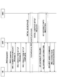
- RRC CONNECTION RECONFIGURATION signal the transmission timing of the connection reconfiguration signal will be described with reference to FIG.
- the user terminal UE transmits a RACH preamble to the radio base station eNB.
- the radio base station eNB transmits a RACH response to the user terminal UE.
- the user terminal UE transmits RRC CONNECTION REQUEST (Message 3) to the radio base station eNB.
- the radio base station eNB transmits an RRC CONNECTION SETUP (Message 4) to the user terminal UE.
- the user terminal UE When receiving the RRC CONNECTION SETUP (Message 4), the user terminal UE transmits RRC CONNECTION SETUP COMPLETE to the radio base station eNB.
- the radio base station eNB When receiving the RRC CONNECTION SETUP COMPLETE, the radio base station eNB transmits INITIAL UE MESSAGE to the mobility management node MME. Thereby, Authentication and NAS security procedure are performed between the user terminal UE and the mobility management node MME. Thereafter, the mobility management node MME transmits INITIAL CONTEXT SETUP REQUEST to the radio base station eNB.
- the radio base station eNB transmits UE CAPABILITY ENQUIRY to the user terminal UE.
- the user terminal UE transmits UE CAPABILITY INFORMATION to the radio base station eNB.
- the radio base station eNB transmits UE CAPABILITY INFO INDICATION to the mobility management node MME.
- the radio base station eNB transmits SECURITY MODE COMMAND to the user terminal UE. Thereafter, the radio base station eNB transmits RRC CONNECTION RECONFIGURATION including notification information (CSI-RS-Config) to the user terminal UE.
- CSI-RS-Config notification information
- the user terminal UE transmits RRC CONNECTION RECONFIGURATION COMP to the radio base station eNB.
- the radio base station eNB After receiving the RRC CONNECTION RECONFIGURATION COMP, that is, after the Ambiguity period has elapsed, the radio base station eNB transmits downlink data addressed to the user terminal UE and transmits downlink data of adjacent cells in the subframe in which the CSI-RS is transmitted. Stop (CSI-RS / muting) is started.
- the radio base station individually signals the CSI-RS transmission parameters to the user terminal at the transmission timing of the connection reconfiguration signal (included in the connection reconfiguration signal). In this case, it is possible to reduce notification of useless information to other user terminals.
- At least one of the system bandwidth, the information of the subframe in which broadcast information (for example, SIB1) is multiplexed, and the information of the subframe in which paging information is multiplexed is transmitted by CSI-RS. What is necessary is just to prescribe
- the user terminal When the user terminal receives the notification information notified from the radio base station, the user terminal measures the channel quality based on the notification information. Specifically, the user terminal refers to the CSI-RS transmission parameter notified from each transmission point and the system information (system bandwidth, etc.) associated with the CSI-RS transmission parameter, and transmits each transmission point. Channel quality is measured based on the CSI-RS transmitted from. Thereby, since the user terminal can grasp the correspondence between the CSI-RS transmitted from each transmission point and the system information, it can appropriately measure the channel quality for a plurality of transmission points (for example, a serving cell and a neighboring cell). .
- a plurality of transmission points for example, a serving cell and a neighboring cell.
- the radio base station can acquire information indicating the CSI-RS transmission parameter of the neighboring cell and system information such as the system bandwidth from the radio base station of the neighboring cell.
- a predetermined radio base station serving point
- the user terminal can grasp system information (system bandwidth, etc.) corresponding to the CSI-RS transmission parameter notified from the transmission point (here, TP # 2) other than the serving point.
- CSI-RS transmission parameters, subframe information in which broadcast information (MIB and / or SIB, etc.), paging information, and the like are multiplexed are notified to user terminals with individual signals, so that CSI- Collision between a subframe in which RS is transmitted and a subframe in which paging information and the like are multiplexed can be avoided.
- system information of adjacent transmission points that perform CSI-RS transmission is aggregated and notified to a user terminal as a predetermined information element (IE) by an individual signal (for example, RRC signaling).
- the system information of each transmission point includes system bandwidth, information on subframes in which broadcast information included in MIB, SIB, etc. is multiplexed, information on subframes in which paging information is multiplexed, the number of CSI-RS antenna ports, etc. Is mentioned.
- system information can be signaled to the user terminal as a predetermined information element (IE) at the timing of transmitting the connection reconfiguration signal.
- IE information element
- PhysicalConfigDedicated IE used to specify the physical channel configuration specific to the user terminal
- these system information (subframe information, paging information in which broadcast information included in system bandwidth, MIB, SIB, etc. is multiplexed) Are notified to the user terminal by RRC signaling.
- the amount of higher layer signaling can be reduced by aggregating system information at a plurality of transmission points into predetermined information elements and notifying the user terminal with individual signals.
- a predetermined radio base station selects information used by the user terminal when measuring channel quality from each system information of each transmission point, and the predetermined information The user terminal is notified by an individual signal as an element.
- the radio base station selects the minimum system bandwidth from the system bandwidth of each transmission point and notifies the user terminal. For example, when the system bands operated by adjacent transmission points (for example, the first transmission point (TP # 1) and the second transmission point (TP # 2)) are a 5 MHz band and a 10 MHz band, respectively, A transmission point (for example, a serving point) selects a 5 MHz band and notifies the user terminal.
- the system bands operated by adjacent transmission points for example, the first transmission point (TP # 1) and the second transmission point (TP # 2)
- a transmission point for example, a serving point
- a relatively narrow system bandwidth for example, 5 MHz
- a relatively wide system bandwidth for example, 10 MHz
- the radio base station selects at least one of the transmission points as subframe information on which paging information is multiplexed, and notifies the user terminal of subframe information on which paging information is multiplexed. For example, at adjacent transmission points (for example, TP # 1 and TP # 2), TP # 1 transmits paging information with subframe numbers # 4 and # 9, and TP # 2 has paging information with subframe number # 9. Is transmitted, subframe numbers # 4 and # 9 are selected and notified to the user terminal.
- adjacent transmission points for example, TP # 1 and TP # 2
- TP # 1 transmits paging information with subframe numbers # 4 and # 9
- TP # 2 has paging information with subframe number # 9. Is transmitted, subframe numbers # 4 and # 9 are selected and notified to the user terminal.
- the user terminal can grasp the subframe in which the paging information is transmitted from each adjacent transmission point, it is possible to effectively avoid the collision with the CSI-RS.
- the same control can be performed for subframe information in which broadcast information included in MIB, SIB, and the like is multiplexed.
- the radio base station selects the minimum number of antenna ports from among the CSI-RS antenna ports at each transmission point (radio base station) as the number of antenna ports used for CSI-RS transmission, and sends it to the user terminal. Notice. For example, when the number of CSI-RS antenna ports of TP # 1 is 2 and the number of CSI-RS antenna ports of TP # 2 is 4, 2 is notified as the number of CSI-RS antenna ports.
- the amount of RRC signaling can be reduced as compared to the case of notifying the antenna port of each transmission point. Further, since the number of antenna ports for performing channel quality measurement using CSI-RS can be reduced in the user terminal, it is possible to suppress the complexity of processing in the user terminal.
- the user terminal may be notified of the number of CSI-RS antenna ports at the transmission point of each cell.
- the radio base station notifies the user terminal of the system bandwidth of each transmission point as the system bandwidth.
- the system bands operated by TP # 1 and TP # 2 are the 5 MHz band and the 10 MHz band, respectively, both the 5 MHz band and the 10 MHz band are notified to the user terminal by individual signals (RRC signaling).
- the subframe information in which the paging information is multiplexed is notified in association with each transmission point and the subframe information. For example, when paging information is transmitted with subframe numbers # 4 and # 9 in TP # 1, and paging information is transmitted with subframe number # 9 in TP # 2, "paging information is multiplexed as subframe information" Information of subframe numbers # 4 and # 9 is notified by TP # 1, and information of subframe number # 9 "is notified by TP # 2. Note that it is possible to similarly control subframe information in which broadcast information included in MIB, SIB, and the like is multiplexed.
- the radio base station notifies the number of antenna ports used for CSI-RS transmission in association with the number of CSI-RS antenna ports at each transmission point and the transmission point. For example, when the number of CSI-RS antenna ports of TP # 1 is 2 and the number of CSI-RS antenna ports of TP # 2 is 4, “number of antenna ports of TP # 1 and number of antenna ports of TP # 2” Information "4" is notified.
- the user terminal transmits CSI-s transmitted from a plurality of transmission points. Based on the RS transmission parameters, the channel quality for each transmission point can be appropriately measured. Further, even when the cell IDs of adjacent cells are the same, the user terminal can appropriately grasp the system information for the CSI-RS transmission parameter notified from each transmission point and measure the channel quality.
- the system information of each transmission point and the index number of the CSI-RS transmission parameter are notified without tying them together. Also good.
- a predetermined system band used for channel quality measurement is selected from the notified system information of each transmission point.
- the user terminal selects appropriate system information from each system information. That is, in the said aspect 1, although a radio base station selects, a user terminal will select here.
- the radio base station when the radio base station notifies the user terminal of a plurality of information (for example, 5 MHz band and 10 MHz band) as the system bandwidth, the minimum system bandwidth (in this case, 5 MHz band) is selected on the user terminal side.
- a plurality of information for example, 5 MHz band and 10 MHz band
- the minimum system bandwidth in this case, 5 MHz band
- FIG. 5 is an explanatory diagram of the system configuration of the wireless communication system according to the present embodiment.
- the radio communication system shown in FIG. 5 is a system that includes, for example, the LTE system or SUPER 3G.
- carrier aggregation in which a plurality of fundamental frequency blocks with the system band of the LTE system as a unit is integrated is used.
- this wireless communication system may be called IMT-Advanced or 4G.
- the radio communication system 1 includes radio base stations 20A and 20B and a plurality of first and second user terminals 10A and 10B communicating with the radio base stations 20A and 20B. ing.
- the radio base stations 20 ⁇ / b> A and 20 ⁇ / b> B are connected to the higher station apparatus 30, and the higher station apparatus 30 is connected to the core network 40.
- the radio base stations 20A and 20B are connected to each other by wired connection or wireless connection.
- the first and second user terminals 10A and 10B can communicate with the radio base stations 20A and 20B in the cells C1 and C2.
- the upper station device 30 includes, for example, an access gateway device, a radio network controller (RNC), a mobility management entity (MME), and the like, but is not limited thereto.
- RNC radio network controller
- MME mobility management entity
- the first and second user terminals 10A and 10B include an LTE terminal and an LTE-A terminal. In the following, the description will proceed as the first and second user terminals unless otherwise specified. For convenience of explanation, it is assumed that the first and second user terminals 10A and 10B communicate wirelessly with the radio base stations 20A and 20B, but more generally both mobile terminal devices and fixed terminal devices are used.
- the user equipment (UE) may be included.
- OFDMA Orthogonal Frequency Division Multiple Access
- SC-FDMA Single Carrier-Frequency Division Multiple Access
- the wireless access method is not limited to this.
- OFDMA is a multi-carrier transmission scheme that performs communication by dividing a frequency band into a plurality of narrow frequency bands (subcarriers) and mapping data to each subcarrier.
- SC-FDMA is a single carrier transmission method that reduces interference between terminals by dividing a system band into bands each consisting of one or continuous resource blocks for each terminal, and a plurality of terminals using different bands. .
- the downlink communication channel includes PDSCH (Physical Downlink Shared Channel) as a downlink data channel shared by the first and second user terminals 10A and 10B, and a downlink L1 / L2 control channel (PDCCH, PCFICH, PHICH) Have Transmission data and higher control information are transmitted by the PDSCH.
- PDSCH and PUSCH scheduling information and the like are transmitted by PDCCH (Physical Downlink Control Channel).
- the number of OFDM symbols used for PDCCH is transmitted by PCFICH (Physical Control Format Indicator Channel).
- HARQ ACK / NACK for PUSCH is transmitted by PHICH (Physical Hybrid-ARQ Indicator Channel).
- the uplink communication channel has PUSCH (Physical Uplink Shared Channel) as an uplink data channel shared by each user terminal and PUCCH (Physical Uplink Control Channel) as an uplink control channel. Transmission data and higher control information are transmitted by this PUSCH. Also, downlink radio quality information (CQI), ACK / NACK, and the like are transmitted by PUCCH.
- PUSCH Physical Uplink Shared Channel
- PUCCH Physical Uplink Control Channel
- the radio base station 20 includes a transmission / reception antenna 201, an amplifier unit 202, a transmission / reception unit (notification unit) 203, a baseband signal processing unit 204, a call processing unit 205, and a transmission path interface 206. Transmission data transmitted from the radio base station 20 to the user terminal via the downlink is input from the higher station apparatus 30 to the baseband signal processing unit 204 via the transmission path interface 206.
- the downlink data channel signal is transmitted from the RCP layer, such as PDCP layer processing, transmission data division / combination, RLC (Radio Link Control) retransmission control transmission processing, and MAC (Medium Access).
- RCP layer such as PDCP layer processing, transmission data division / combination, RLC (Radio Link Control) retransmission control transmission processing, and MAC (Medium Access).
- Control Retransmission control, for example, HARQ transmission processing, scheduling, transmission format selection, channel coding, inverse fast Fourier transform (IFFT) processing, and precoding processing are performed.
- transmission processing such as channel coding and inverse fast Fourier transform is performed on the signal of the physical downlink control channel that is the downlink control channel.
- the baseband signal processing unit 204 notifies the control information for each user terminal 10 to perform radio communication with the radio base station 20 to the user terminals 10 connected to the same cell through the broadcast channel.
- the information for communication in the cell includes, for example, system bandwidth in uplink or downlink, and root sequence identification information (Root Sequence) for generating a random access preamble signal in PRACH (Physical Random Access Channel). Index) etc. are included.
- the transmission / reception unit 203 converts the baseband signal output from the baseband signal processing unit 204 into a radio frequency band.
- the amplifier unit 202 amplifies the radio frequency signal subjected to frequency conversion and outputs the amplified signal to the transmission / reception antenna 201.
- a radio frequency signal received by the transmission / reception antenna 201 is amplified by the amplifier unit 202 and frequency-converted by the transmission / reception unit 203 to be a baseband signal. And is input to the baseband signal processing unit 204.
- the baseband signal processing unit 204 performs FFT processing, IDFT processing, error correction decoding, MAC retransmission control reception processing, RLC layer, PDCP layer reception processing on transmission data included in the baseband signal received in the uplink I do.
- the decoded signal is transferred to the higher station apparatus 30 via the transmission path interface 206.
- the call processing unit 205 performs call processing such as communication channel setting and release, state management of the radio base station 20, and radio resource management.
- the user terminal 10 includes a transmission / reception antenna 101, an amplifier unit 102, a transmission / reception unit (reception unit) 103, a baseband signal processing unit 104, and an application unit 105.
- a radio frequency signal received by the transmission / reception antenna 101 is amplified by the amplifier unit 102, frequency-converted by the transmission / reception unit 103, and converted into a baseband signal.
- the baseband signal is subjected to FFT processing, error correction decoding, retransmission control reception processing, and the like by the baseband signal processing unit 104.
- downlink transmission data is transferred to the application unit 105.
- the application unit 105 performs processing related to layers higher than the physical layer and the MAC layer. Also, the broadcast information in the downlink data is also transferred to the application unit 105.
- uplink transmission data is input from the application unit 105 to the baseband signal processing unit 104.
- the baseband signal processing unit 104 performs mapping processing, retransmission control (HARQ) transmission processing, channel coding, DFT processing, and IFFT processing.
- the transmission / reception unit 103 converts the baseband signal output from the baseband signal processing unit 104 into a radio frequency band. Thereafter, the amplifier unit 102 amplifies the frequency-converted radio frequency signal and transmits it from the transmission / reception antenna 101.
- HARQ retransmission control
- each functional block in FIG. 8 is mainly processing contents of the baseband processing unit. Further, the functional block diagram of FIG. 8 is simplified, and is assumed to have a configuration normally provided in the baseband processing unit. Also, in the following description, an index for specifying a resource where CSI-RS is arranged is described as a CSI-RS index.
- the radio base station 20 includes a CSI-RS arrangement unit 211, a CSI-RS transmission parameter generation unit 212, and a notification information generation unit 213.
- the CSI-RS arrangement unit 211 arranges the CSI-RS in the CSI-RS transmission resource in the resource block according to the number of CSI-RS ports.
- the CSI-RS transmission parameter generation unit 212 generates transmission parameters (position, sequence, transmission power, etc.) for specifying the CSI-RS.
- the CSI-RS transmission parameter generated by the CSI-RS parameter generation unit 212 is output to the notification information generation unit 213.
- the notification information generation unit 209 generates notification information (individual signal) composed of information indicating CSI-RS transmission parameters and system information of a transmission point for transmitting CSI-RS.
- the system information include system bandwidth, information on subframes in which broadcast information (MIB and / or SIB) is multiplexed, information on subframes in which paging information is multiplexed, and the like.
- the number of CSI-RS antenna ports may be included.
- the notification information generation unit 213 and the neighboring cell with the same cell ID and the CSI-RS transmission parameter Notification information including cell system information can also be generated.
- the notification information generated by the notification information generation unit 213 is notified to the user terminal by an individual signal (upper layer signaling) via the transmission / reception unit 203.
- FIG. 9 is an explanatory diagram of functional blocks for measuring channel quality (mainly CQI) by the user terminal. Note that each functional block in FIG. 9 is mainly processing contents of the baseband processing unit. Further, the functional blocks shown in FIG. 9 are simplified for the purpose of explaining the present invention, and the configuration normally provided in the baseband processing unit is provided.
- the user terminal 10 includes a transmission / reception unit 103, a notification information acquisition unit 106, a user data demodulation unit 107, and a channel quality measurement unit 108.
- the transmission / reception unit 103 receives CSI-RS and notification information (individual signal) from the radio base station 20.
- User data demodulation unit 107 demodulates user data received via transmission / reception unit 103. Instead of providing the user data demodulation unit 107, the notification information acquisition unit 106 may perform user data demodulation processing.
- the notification information acquisition unit 106 demodulates the notification information (individual signal), subframe information in which CSI-RS transmission parameters, system bandwidth, and paging are multiplexed, and broadcast information (subcodes in which MIB, SIB, etc. are multiplexed). Acquires frame information, etc.
- the notification information acquisition unit 106 outputs the acquired information to the channel quality measurement unit 108.
- the channel quality measurement unit 108 measures the channel quality using the CSI-RS transmission parameter and the system information (system bandwidth, etc.) of the transmission point that transmitted the CSI-RS, and obtains the CSI from the measured channel quality. In this case, since the CSI-RS is not multiplexed in the subframe in which the paging information and the broadcast information are multiplexed, the channel quality is not measured and the channel quality is measured using the CSI-RS in the other subframe. .
- Channel quality measurement section 108 outputs the measured CSI information to transmission / reception section 103.
- the transmission / reception unit 103 transmits the CSI information output from the channel quality measurement unit 108 to the radio base station to which it is connected. Further, the channel quality measurement unit 108 measures the channel quality of adjacent cells having the same cell ID in addition to the channel quality of the own cell (serving cell).
- the present invention is not limited to the above embodiment, and can be implemented with various modifications.
- the first mode and the second mode can be combined as appropriate, and the first mode and the second mode in the second mode can also be combined as appropriate.
- Other modifications can be made without departing from the scope of the present invention.
Abstract
ユーザ端末に対して複数の送信ポイントからCSI-RS送信パラメータが通知される場合であっても、ユーザ端末におけるチャネル品質測定を適切に行うこと。複数の無線基地局と、複数の無線基地局からチャネル状態測定用の参照信号を受信可能なユーザ端末と、の無線通信方法であって、無線基地局が、参照信号の送信パラメータを示す情報と、参照信号の送信を行う無線基地局のシステム帯域幅を少なくとも含むシステム情報と、で構成される通知情報を生成し、生成した通知情報を上位レイヤシグナリングによりユーザ端末に対して通知し、ユーザ端末が、受信した通知情報に基づいて、チャネル品質を測定する。
Description
本発明は、無線通信方法、無線基地局、ユーザ端末及び無線通信システムに関する。
UMTS(Universal Mobile Telecommunications System)ネットワークにおいては、周波数利用効率の向上、データレートの向上を目的として、HSDPA(High Speed Downlink Packet Access)やHSUPA(High Speed Uplink Packet Access)を採用することにより、W-CDMA(Wideband Code Division Multiple Access)をベースとしたシステムの特徴を最大限に引き出すことが行われている。このUMTSネットワークについては、更なる高速データレート、低遅延などを目的としてロングタームエボリューション(LTE:Long Term Evolution)が合意された(非特許文献1)。LTEシステムでは、多重方式として、下り回線(下りリンク)にW-CDMAとは異なるOFDMA(Orthogonal Frequency Division Multiple Access)が適用される。
第3世代のシステムは、概して5MHzの固定帯域を用いて、下り回線で最大2Mbps程度の伝送レートを実現できる。一方、LTEシステムでは、1.4MHz~20MHzの可変帯域を用いて、下り回線で最大300Mbps及び上り回線で75Mbps程度の伝送レートを実現できる。また、UMTSネットワークにおいては、更なる広帯域化及び高速化を目的として、LTEの後継のシステムも検討されている(例えば、LTEアドバンスト(LTE-Aシステム))。
LTEシステムの下りリンクにおいて、セル共通の参照信号であるCRS(Common Reference Signal)が定められている。このCRSは、送信データの復調に用いられる他、スケジューリングや適応制御のための下りリンクのチャネル品質(CQI:Channel Quality Indicator)測定、並びに、セルサーチやハンドオーバのための下りの平均的な伝搬路状態の測定(モビリティ測定)に用いられる。
一方、LTEの後継システム(LTE-Aシステム)の下りリンクにおいては、CRSに加えて、チャネル状態測定用の参照信号としてCSI-RS(Channel State Information Reference Signal)が検討されている。CSI-RSは、協調マルチポイント送受信(CoMP:Coordinated Multiple Point)等の複数セル間によるデータチャネル信号の送受信を考慮して、複数セルのチャネル品質測定に対応している。CSI-RSは、隣接セルのチャネル品質測定に用いられる点で、サービングセルのみのチャネル品質測定に用いられるCRSと相違している。
3GPP, TR25.912 (V7.1.0), "Feasibility study for Evolved UTRA and UTRAN", Sept. 2006
LTE-Aの1つであるRel-10 LTEにおいては、従来のセルラ環境に加えてローカルエリア環境を重視したHeterogeneous Network(Het Net)構成が採用されている。また、上述したように、LTE Rel-11以降において、システム性能を向上させるためにセル間直交化を実現する技術として協調マルチポイント送受信(CoMP)が検討されている。
複数の無線基地局(送信ポイント)とユーザ端末間で無線通信を行う場合、ユーザ端末は、複数の送信ポイントから送信されるCSI-RSに基づいて、各送信ポイントに対するチャネル品質を測定する。この際、ユーザ端末は、無線基地局から通知されるCSI-RSの送信パラメータ(位置、系列及び送信電力等)を示す情報(CSI-RS-Config)を参照して、各送信ポイントに対するチャネル品質を測定する必要がある。しかし、この場合、ユーザ端末において、各送信ポイントから送信される複数のCSI-RSと、各送信ポイントのシステム情報(システム帯域幅等)との対応を把握できず、チャネル品質の測定精度が低下するおそれがある。
また、Het Netのような階層型ネットワークにおいて、相対的に広いエリアをカバーする大セルの無線基地局(例えば、マクロ基地局)と、相対的に狭いエリアをカバーする小セルの無線基地局(例えば、ピコ基地局、フェムト基地局、RRH基地局等)とで同一のセルIDを適用して無線通信を制御することが検討されている。この場合、セルIDとCSI-RS送信パラメータが括りつけられている場合であっても、ユーザ端末は、複数の送信ポイントから送信されるCSI-RSにそれぞれ対応するシステム情報を把握できないおそれがある。その結果、ユーザ端末におけるチャネル品質測定の精度が低下するおそれがある。
本発明はかかる点に鑑みてなされたものであり、ユーザ端末に対して複数の送信ポイントからCSI-RS送信パラメータが通知される場合であっても、ユーザ端末におけるチャネル品質測定を適切に行うことができる無線通信方法、無線基地局、ユーザ端末及び無線通信システムを提供することを目的とする。
本発明の無線通信方法は、複数の無線基地局と、前記複数の無線基地局からチャネル状態測定用の参照信号を受信可能なユーザ端末と、の無線通信方法であって、前記無線基地局が、前記参照信号の送信パラメータを示す情報と、前記参照信号の送信を行う無線基地局のシステム帯域幅を少なくとも含むシステム情報と、で構成される通知情報を生成する工程と、生成した通知情報を上位レイヤシグナリングによりユーザ端末に対して通知する工程と、前記ユーザ端末が、受信した通知情報に基づいて、チャネル品質を測定する工程と、を有することを特徴とする。
本発明によれば、ユーザ端末に対して複数の送信ポイントからCSI-RS送信パラメータが通知される場合であっても、ユーザ端末におけるチャネル品質測定を適切に行うことができる。
本発明に係る無線通信方法、無線基地局、ユーザ端末及び無線通信システムは、次世代無線通信システムの1つであるLTE/LTE-Aシステム等に適用可能である。はじめに、LTE/LTE-AシステムにおけるHet Netの概要について説明する。なお、以下の説明においては、マクロセル等の大規模セル(以下、「マクロセル」と記す)と、ピコセルやフェムトセル等の小規模セル(以下、「ピコセル」と記す)を例に挙げて説明するが、無線通信システムの構成はこれに限られない。
図1にHet Netの概要を示す。Het Netは、既存のマクロセルC1に加えて、ピコセルC2等の様々な形態のセルをオーバレイした階層型ネットワークである。このHet Netにおいては、相対的に広いエリアをカバーするマクロセルC1の送信ポイント(無線基地局(以下、「マクロ基地局」と記す))B1は、相対的に狭いエリアをカバーするピコセルC2の送信ポイント(無線基地局(以下、「ピコ基地局」と記す))B2よりも下り送信電力が大きく設定されている。なお、マクロ基地局B1とピコ基地局B2との情報(タイミング情報やスケジューリングなどの無線リソース割り当て情報等)のやり取りは、有線接続(例えば、X2インターフェース)を介して行うことができる。
また、LTE-Aシステムでは、セル間直交化を実現するための技術として、協調マルチポイント送受信(CoMP)技術が検討されている。このCoMP送受信では、1つあるいは複数のユーザ端末UEに対して複数の送信ポイントが協調して送受信の信号処理を行う。例えば、下りリンクでは、プリコーディングを適用する複数セル同時送信、協調スケジューリング/ビームフォーミングなどが検討されている。これらのCoMP送受信技術の適用により、特にセル端に位置するユーザ端末UEのスループット特性の改善が期待される。
CoMP送受信技術を適用するためには、ユーザ端末から無線基地局に、複数の送信ポイントに対するチャネル品質指標(CQI:Channel Quality Indicator)等のチャネル状態情報(CSI:Channel State Information)をフィードバックする必要がある。また、CoMP送受信を実現する構成としては、無線基地局(無線基地局eNB)に対して光ファイバ等で接続された複数の遠隔無線装置(RRE:Remote Radio Equipment)とを含む構成(RRE構成に基づく集中制御)等が検討されている。なお、本実施の形態に係る無線基地局(送信ポイント)は、無線基地局eNB、遠隔無線装置を含めた概念である。
上述のような複数セル間の連携技術を想定すると、ユーザ端末は自セルのみならず、他セルに(複数の送信ポイント)おけるチャネル品質を測定して、サービングセル等にフィードバックする必要がある。この場合、ユーザ端末は、各送信ポイントから送信されるチャネル状態測定用の参照信号(CSI-RS)に基づいて、セル毎にCSIを生成してフィードバックする。
CSI-RSは、チャネル状態としてのCQI、PMI(Precoding Matrix Indicator)、RI(Rank Indicator)などのチャネル状態の測定に用いられる参照信号である。CSI-RSは、全てのサブフレームに割り当てられるCRSと異なり、所定の周期、例えば10サブフレーム周期で割り当てられる。また、CSI-RSは、位置、系列及び送信電力等の送信パラメータを示す情報(SI-RS-Config)で特定される。CSI-RSの位置には、サブフレームオフセット、周期、サブキャリア-シンボルオフセット(インデックス)が含まれる。
CSI-RSは、LTEで規定される1リソースブロックにおいて、PDCCH(Physical Downlink Control Channel)信号などの制御信号、PDSCH(Physical Downlink Shared Channel)信号などのユーザデータ、CRS(Cell-specific Reference Signal)やDM-RS(Demodulation-Reference Signal)などの他の参照信号と重ならないように割り当てられる。
1リソースブロックは、周波数方向に連続する12サブキャリアと、時間軸方向に連続する14シンボルとで構成される。PAPR(Peak-to-Average Power Ratio)を抑制する観点から、CSI-RSを送信可能なリソースは、時間軸方向に隣接する2つのリソースエレメントがセットで割り当てられる。
図2に示されるCSI-RS構成では、CSI-RS用リソース(参照信号用リソース)として40リソースエレメントが確保されている。この40リソースエレメントには、CSI-RSポート数(アンテナ数)に応じてCSI-RSパターンが設定される。各CSI-RSパターンでは、1つのCSI-RSポートにつき、1つのリソースエレメントがCSI-RS用に割り当てられる。CSI-RSポート数が2の場合、40リソースエレメントの中の2つのリソースエレメントにCSI-RSが割り当てられる。よって、図2Aでは、インデックス#0-#19(CSI Configuration=0-19)で示される20パターンのCSI-RSパターンが設定される。ここでは、説明の便宜上、1パターンを構成するリソースエレメントに同一のインデックスを付している。
CSI-RSポート数が4の場合、40リソースエレメントの中の4つのリソースエレメントにCSI-RSが割り当てられる。よって、図2Bでは、インデックス#0-#9(CSI Configuration=0-9)で示される10パターンのCSI-RSパターンが設定される。CSI-RSポート数が8の場合、40リソースエレメントの中の8つのリソースエレメントにCSI-RSが割り当てられる。よって、図2Cに示すように、インデックス#0-#4(CSI Configuration=0-4)で示される5パターンのCSI-RSパターンが設定される。なお、CSI-RSパターンにおいて、CSI-RSが割り当てられなかったリソースエレメントには、ユーザデータが割り当てられる。そして、CSI-RSは、セル毎に異なるCSI-RSパターン(CSI Configuration)が選択されることで、セル間での干渉が抑えられている。
また、LTE Rel-10においては、CSI-RSを送信するサブフレームと、ページングを多重しているサブフレーム、SIB(System Information Block)やMIB(Master Information Block)等の報知情報を多重しているサブフレーム等とが衝突する場合にはCSI-RSの送信を行わない。無線基地局は、上記ページングなどが多重しているサブフレーム情報をユーザ端末に対して通知する。
ところで、LTE Rel-11以降で検討されている複数セル間の連携技術、例えば、CoMPを想定すると、ユーザ端末は、自セルのみならず、他セルのCSI-RSを用いてチャネル品質を測定することが必要となる。つまり、複数の送信ポイントから通知されるCSI-RS送信パラメータを参照して、各送信ポイントに対するチャネル品質を測定する必要がある。この場合、ユーザ端末は、各送信ポイントから送信される複数のCSI-RS(CSI-RS送信パラメータ)と、各送信ポイントにおけるシステム情報(システム帯域幅等)との対応を把握できないおそれがある。その結果、ユーザ端末が誤ったシステム情報を適用してチャネル品質測定を行うことにより、チャネル品質の測定精度が低下するおそれがある。
一方で、複数セル間の連携技術においては、隣接セルの無線基地局(送信ポイント)が同一のセルIDを適用して、無線通信制御を行うこと(shared cell ID scenario)が検討されている。例えば、カバレッジエリアの少なくとも一部が重なる隣接セル(例えば、マクロセルとピコセル)が同一のセルIDを用いる場合が想定される。また、CoMP送受信において、無線基地局とRREが同一のセルIDを適用して無線通信制御を行う場合等が想定される。
この場合、ユーザ端末は各セルの送信ポイントから送信されるCSI-RSと各セルのシステム情報(例えば、システム帯域幅)との対応関係をセルIDから把握することができない。このため、ユーザ端末が誤ったシステム情報を適用してチャネル品質測定を行うことにより、チャネル品質の測定精度が低下するおそれがある。
例えば、セルIDが同一でシステム帯域幅が異なるマクロセルとピコセルからCSI-RSが送信される場合、各セルのCSI-RSに対してサービングセルのシステム帯域幅を適用する場合、隣接セルのチャネル品質の測定精度が低下する。特に、隣接セルのシステム帯域幅(例えば、5MHz)がサービングセルのシステム帯域幅(例えば、10MHz)より小さい場合には、隣接セルのチャネル品質の測定精度が大幅に低下するおそれがある。
本発明者らは、ユーザ端末が複数の無線基地局(送信ポイント)から送信されたCSI-RSに基づいてチャネル品質測定を行う際に、ユーザ端末が参照するシステム情報(システム帯域幅等)を個別信号(上位レイヤシグナリング)で通知することに着目した。そして、位置、系列及び送信電力等のCSI-RS送信パラメータと、CSI-RSの送信を行う送信ポイントのシステム情報とを対応づけて(括りつけて)ユーザ端末に通知することにより、複数のCSI-RSを受信する場合であってもチャネル品質測定を適切に行うことができることを見出した。
また、本発明者らは、CSI-RSを送信する複数の送信ポイントのシステム情報(システム帯域幅等)を集約して所定の情報エレメントとして、個別信号(上位レイヤシグナリング)でユーザ端末に通知することにより、シグナリング量を低減できることを見出した。
以下に、本実施の形態について図面を参照して詳細に説明する。なお、以下の説明においては、隣接する複数の無線基地局(送信ポイント)が同一のセルIDを適用して、無線通信制御を行う場合(shared cell ID scenario)を例に挙げて説明するが、本実施の形態はこれに限られない。本実施の形態は、ユーザ端末に対して、複数の送信ポイントからCSI-RS送信パラメータが送信される場合であれば適用することができる。
(第1の形態)
第1の形態では、CSI-RSの送信パラメータを示す情報(CSI-RS-Config)とで構成される通知情報と、当該CSI-RSの送信を行う送信ポイントが運用するシステム情報と、を個別信号(例えば、RRCシグナリング)でユーザ端末に通知する。システム情報としては、当該送信ポイントのシステム帯域幅、報知情報(MIB及び/又はSIB等)が多重されるサブフレームの情報、ページング情報が多重されるサブフレームの情報等が挙げられる。また、これらのシステム情報を、CSI-RSの送信パラメータを示す情報(CSI-RS-Config)のパラメータとして規定して、ユーザ端末に通知することができる。
第1の形態では、CSI-RSの送信パラメータを示す情報(CSI-RS-Config)とで構成される通知情報と、当該CSI-RSの送信を行う送信ポイントが運用するシステム情報と、を個別信号(例えば、RRCシグナリング)でユーザ端末に通知する。システム情報としては、当該送信ポイントのシステム帯域幅、報知情報(MIB及び/又はSIB等)が多重されるサブフレームの情報、ページング情報が多重されるサブフレームの情報等が挙げられる。また、これらのシステム情報を、CSI-RSの送信パラメータを示す情報(CSI-RS-Config)のパラメータとして規定して、ユーザ端末に通知することができる。
また、無線基地局は、上記システム情報をSI-RS-Configのパラメータとして規定した情報を、コネクション再構成信号(RRC CONNECTION RECONFIGURATION信号)に含めてユーザ端末に通知することができる。以下に、図3を参照して、コネクション再構成信号の送信タイミングについて説明する。
まず、ユーザ端末UEが無線基地局eNBに対して、RACH preambleを送信する。無線基地局eNBは、RACH preambleを受信したときに、ユーザ端末UEに対して、RACH responseを送信する。次いで、ユーザ端末UEは、無線基地局eNBに対して、RRC CONNECTION REQUEST(Message 3)を送信する。無線基地局eNBは、RRC CONNECTION REQUEST(Message 3)を受信したときに、ユーザ端末UEに対して、RRC CONNECTION SETUP(Message 4)を送信する。
ユーザ端末UEは、RRC CONNECTION SETUP(Message 4)を受信すると、無線基地局eNBに対して、RRC CONNECTION SETUP COMPLETEを送信する。無線基地局eNBは、RRC CONNECTION SETUP COMPLETEを受信すると、移動管理ノードMMEに対して、INITIAL UE MESSAGEを送信する。これにより、ユーザ端末UEと移動管理ノードMMEとの間で、AuthenticationやNAS security procedureが行われる。その後、移動管理ノードMMEは、無線基地局eNBに対して、INITIAL CONTEXT SETUP REQUESTを送信する。
なお、INITIAL CONTEXT SETUP REQUESTにUE CAPABILITYが含まれていない場合、無線基地局eNBは、ユーザ端末UEに対して、UE CAPABILITY ENQUIRYを送信する。ユーザ端末UEは、UE CAPABILITY ENQUIRYを受信したとき、無線基地局eNBに対して、UE CAPABILITY INFORMATIONを送信する。そして、無線基地局eNBは、移動管理ノードMMEに対して、UE CAPABILITY INFO INDICATIONを送信する。
次いで、無線基地局eNBは、ユーザ端末UEに対して、SECURITY MODE COMMANDを送信する。その後、無線基地局eNBは、ユーザ端末UEに対して、通知情報(CSI-RS-Config)を含むRRC CONNECTION RECONFIGURATIONを送信する。
その後、図4に示すように、ユーザ端末UEは、RRC CONNECTION RECONFIGURATIONを受信したときに、無線基地局eNBに対して、RRC CONNECTION RECONFIGURATION COMPを送信する。無線基地局eNBは、RRC CONNECTION RECONFIGURATION COMPを受信した後、すなわち、Ambiguity periodが経過した後、CSI-RSを送信するサブフレームにおけるユーザ端末UE宛ての下りデータの送信及び隣接セルの下りデータの送信停止(CSI-RS/ミューティング)を開始する。
このように、無線基地局は、CSI-RSの送信パラメータをコネクション再構成信号の送信タイミングで(コネクション再構成信号に含めて)、ユーザ端末に対して個別にシグナリングする。この場合、他のユーザ端末に対する無駄な情報の報知を低減することができる。
また、本実施の形態では、システム帯域幅、報知情報(例えば、SIB1)が多重されるサブフレームの情報、ページング情報が多重されるサブフレームの情報のうち、少なくとも一つをCSI-RSの送信パラメータとして規定すればよい。この場合、他のシステム情報についても、コネクション再構成信号の送信タイミングで通知すればよい。
ユーザ端末は、無線基地局から通知された通知情報を受信すると、当該通知情報に基づいてチャネル品質の測定を行う。具体的には、ユーザ端末は、各送信ポイントから通知されるCSI-RS送信パラメータと、当該CSI-RS送信パラメータに対応づけられたシステム情報(システム帯域幅等)を参照して、各送信ポイントから送信されるCSI-RSに基づいてチャネル品質の測定を行う。これにより、ユーザ端末は、各送信ポイントから送信されるCSI-RSとシステム情報の対応を把握できるため、複数の送信ポイント(例えば、サービングセルと隣接セル)に対するチャネル品質を適切に測定することができる。
なお、無線基地局は、隣接セルのCSI-RS送信パラメータを示す情報とシステム帯域幅等のシステム情報等について、隣接セルの無線基地局から取得することができる。例えば、所定の無線基地局(サービングポイント)は、これらの情報を隣接セルの無線基地局からX2インターフェース等により取得することができる。
隣接する無線基地局(送信ポイント)が同一のセルIDを適用して、各送信ポイント(例えば、送信ポイントTP#1と、TP#2)がそれぞれ異なるシステム帯域幅で運用される場合、TP#1をサービングポイントとするユーザ端末は、TP#2のシステム帯域幅を把握することができなくなる。そのため、当該ユーザ端末に対してTP#2からCSI-RSが送信された場合には、TP#1のシステム帯域幅を適用してチャネル品質測定を行うこととなり、チャネル品質の測定精度が低下する問題があった。
一方で、本実施の形態では、ユーザ端末に対して、TP#2が通知するCSI-RS送信パラメータを示す情報と当該TP#2のシステム情報(システム帯域幅等)が括りつけられた通知情報が個別にシグナリングされる。このため、ユーザ端末は、サービングポイント以外の送信ポイント(ここでは、TP#2)から通知されるCSI-RS送信パラメータに対応するシステム情報(システム帯域幅等)を把握できる。これにより、隣接する複数セルで同一のセルIDが適用されるであっても、複数セルから送信されたCSI-RSに基づいて、各セルのチャネル品質測定を適切に行うことができる。
また、CSI-RS送信パラメータと、報知情報(MIB及び/又はSIB等)やページング情報等が多重されるサブフレームの情報をユーザ端末に個別信号で通知することにより、複数セル間において、CSI-RSを送信するサブフレームとページング情報等が多重されるサブフレームの衝突を回避することができる。
(第2の形態)
第2の形態では、CSI-RSの送信を行う隣接する送信ポイントのシステム情報を集約し、所定の情報エレメント(IE:Information Element)として個別信号(例えば、RRCシグナリング)でユーザ端末に通知する。各送信ポイントのシステム情報としては、システム帯域幅、MIBやSIB等に含まれる報知情報が多重されるサブフレームの情報、ページング情報が多重されるサブフレームの情報、CSI-RSのアンテナポート数等が挙げられる。
第2の形態では、CSI-RSの送信を行う隣接する送信ポイントのシステム情報を集約し、所定の情報エレメント(IE:Information Element)として個別信号(例えば、RRCシグナリング)でユーザ端末に通知する。各送信ポイントのシステム情報としては、システム帯域幅、MIBやSIB等に含まれる報知情報が多重されるサブフレームの情報、ページング情報が多重されるサブフレームの情報、CSI-RSのアンテナポート数等が挙げられる。
これらのシステム情報は、コネクション再構成信号を送信するタイミングで、所定の情報エレメント(IE:Information Element)としてユーザ端末にシグナリングすることができる。例えば、ユーザ端末固有の物理チャネル構成を規定するために使用されるPhysicalConfigDedicated IEとして、これらのシステム情報(システム帯域幅、MIB、SIB等に含まれる報知情報が多重されるサブフレームの情報、ページング情報が多重されるサブフレームの情報、CSI-RSのアンテナポート数等)をRRCシグナリングでユーザ端末に通知する。
このように、複数の送信ポイントにおけるシステム情報を所定の情報エレメントに集約してユーザ端末に個別信号で通知することにより、上位レイヤシグナリング量を低減することができる。
また、複数の送信ポイントにおけるシステム情報(システム帯域幅等)を集約して通知する際、各送信ポイントのシステム情報からユーザ端末がチャネル品質測定の際に利用する情報を選択して通知する場合(態様1)と、各送信ポイントのシステム情報をそれぞれ通知する場合(態様2)を適用することができる。以下に、態様1、2について説明する。
<態様1>
態様1では、所定の無線基地局(例えば、ユーザ端末が接続する無線基地局)が、各送信ポイントの各システム情報からユーザ端末がチャネル品質測定の際に利用する情報を選択し、所定の情報エレメントとして個別信号でユーザ端末に通知する。
態様1では、所定の無線基地局(例えば、ユーザ端末が接続する無線基地局)が、各送信ポイントの各システム情報からユーザ端末がチャネル品質測定の際に利用する情報を選択し、所定の情報エレメントとして個別信号でユーザ端末に通知する。
無線基地局は、各送信ポイントのシステム帯域の中から最小のシステム帯域幅を選択してユーザ端末に通知する。例えば、隣接する送信ポイント(例えば、第1の送信ポイント(TP#1)と第2の送信ポイント(TP#2))が運用するシステム帯域が、それぞれ5MHz帯域と10MHz帯域である場合、所定の送信ポイント(例えば、サービングポイント)は、5MHz帯域を選択してユーザ端末に通知する。
これは、相対的にシステム帯域幅が狭い(例えば、5MHz)送信ポイントから送信されたCSI-RSに基づいてチャネル品質測定を行う場合、相対的に広いシステム帯域幅(例えば、10MHz)を適用すると、チャネル品質測定が行えない又は精度が著しく低下するためである。このように、各送信ポイントのシステム帯域の中から最小のシステム帯域幅を選択して通知することにより、ユーザ端末は複数の送信ポイントについて、チャネル品質測定を所定品質以上で行うことが可能となる。
また、無線基地局は、ページング情報が多重されるサブフレームの情報として、少なくとも各送信ポイントのいずれかがページング情報を多重するサブフレームの情報を選択してユーザ端末に通知する。例えば、隣接する送信ポイント(例えば、TP#1とTP#2)において、TP#1がサブフレーム番号#4と#9でページング情報を送信し、TP#2がサブフレーム番号#9でページング情報を送信する場合、サブフレーム番号#4と#9を選択してユーザ端末に通知する。
これにより、ユーザ端末は、隣接する各送信ポイントからページング情報が送信されるサブフレームを把握することができるため、CSI-RSとの衝突を効果的に回避することが可能となる。なお、MIBやSIB等に含まれる報知情報が多重されるサブフレームの情報についても、同様に制御することができる。
また、無線基地局は、CSI-RSの送信に用いるアンテナポート数として、各送信ポイント(無線基地局)におけるCSI-RSのアンテナポート数の中から最小のアンテナポート数を選択してユーザ端末に通知する。例えば、TP#1のCSI-RSのアンテナポート数が2、TP#2のCSI-RSのアンテナポート数が4である場合、CSI-RSのアンテナポート数として2が通知される。
ユーザ端末に最小のCSI-RSのアンテナポート数を通知することにより、各送信ポイントのアンテナポートをそれぞれ通知する場合と比較して、RRCシグナリング量を低減することができる。また、ユーザ端末において、CSI-RSを用いてチャネル品質測定を行うアンテナポート数の組合せを低減できるため、ユーザ端末における処理の複雑化を抑制することができる。
なお、各セルの送信ポイントにおけるCSI-RSのアンテナポート数をユーザ端末に通知してもよい。
<態様2>
態様2では、複数の送信ポイントのシステム情報を所定の情報エレメントに集約してユーザ端末に個別信号で通知する際に、無線基地局が各送信ポイントのシステム情報をそれぞれユーザ端末に通知する。この場合、各システム情報(システム帯域幅、報知情報が多重されるサブフレームの情報、ページング情報が多重されるサブフレームの情報、CSI-RSのアンテナポート数等)について、各送信ポイントの情報をそれぞれ通知する。
態様2では、複数の送信ポイントのシステム情報を所定の情報エレメントに集約してユーザ端末に個別信号で通知する際に、無線基地局が各送信ポイントのシステム情報をそれぞれユーザ端末に通知する。この場合、各システム情報(システム帯域幅、報知情報が多重されるサブフレームの情報、ページング情報が多重されるサブフレームの情報、CSI-RSのアンテナポート数等)について、各送信ポイントの情報をそれぞれ通知する。
例えば、無線基地局は、システム帯域幅として、各送信ポイントのシステム帯域をユーザ端末に通知する。TP#1とTP#2が運用するシステム帯域が、それぞれ5MHz帯域と10MHz帯域である場合、5MHz帯域と10MHz帯域の双方をユーザ端末に個別信号(RRCシグナリング)で通知する。
また、ページング情報が多重されるサブフレーム情報について、各送信ポイントとサブフレーム情報とを関連付けて通知する。例えば、TP#1においてページング情報がサブフレーム番号#4と#9で送信され、TP#2においてページング情報がサブフレーム番号#9で送信される場合、ページング情報が多重されるサブフレーム情報として“TP#1でサブフレーム番号#4、#9、TP#2でサブフレーム番号#9”という情報が通知される。なお、MIB、SIB等に含まれる報知情報が多重されるサブフレームの情報についても、同様に制御することができる。
また、無線基地局は、CSI-RSの送信に用いるアンテナポート数として、各送信ポイントのCSI-RSのアンテナポート数と送信ポイントと関連付けてそれぞれ通知する。例えば、TP#1のCSI-RSのアンテナポート数が2、TP#2のCSI-RSのアンテナポート数が4である場合、“TP#1のアンテナポート数2、TP#2のアンテナポート数4”という情報が通知される。
なお、態様2においては、各送信ポイントのシステム情報と、当該送信ポイントから送信されるCSI-RSパラメータのインデックスを括りつけておくことにより、ユーザ端末が、複数の送信ポイントから送信されるCSI-RS送信パラメータに基づいて、各送信ポイントに対するチャネル品質を適切に測定することができる。また、隣接するセルのセルIDが同じ場合であっても、ユーザ端末は各送信ポイントから通知されるCSI-RS送信パラメータに対するシステム情報を適切に把握して、チャネル品質を測定することができる。
また、態様2で示すように、各送信ポイントのシステム情報をそれぞれ個別信号でユーザ端末に通知する場合に、各送信ポイントのシステム情報とCSI-RS送信パラメータのインデックス番号を括りつけず通知してもよい。この場合、ユーザ端末側において、通知された各送信ポイントのシステム情報の中から、チャネル品質測定に使用する所定のシステム帯域を選択する。例えば、上記態様1と同様に、ユーザ端末が、各システム情報からそれぞれ適切なシステム情報を選択する。つまり、上記態様1では、無線基地局が選択するが、ここでは、ユーザ端末が選択することとなる。例えば、無線基地局が、システム帯域幅として複数の情報(例えば、5MHz帯域と10MHz帯域)をユーザ端末に通知した場合、ユーザ端末側で最小のシステム帯域幅(この場合、5MHz帯域)を選択して、チャネル品質測定を行うことができる。
(無線通信システム)
ここで、本実施の形態に係る無線通信システムについて詳細に説明する。図5は、本実施の形態に係る無線通信システムのシステム構成の説明図である。なお、図5に示す無線通信システムは、例えば、LTEシステム或いは、SUPER 3Gが包含されるシステムである。この無線通信システムでは、LTEシステムのシステム帯域を一単位とする複数の基本周波数ブロックを一体としたキャリアアグリゲーションが用いられている。また、この無線通信システムは、IMT-Advancedと呼ばれても良く、4Gと呼ばれても良い。
ここで、本実施の形態に係る無線通信システムについて詳細に説明する。図5は、本実施の形態に係る無線通信システムのシステム構成の説明図である。なお、図5に示す無線通信システムは、例えば、LTEシステム或いは、SUPER 3Gが包含されるシステムである。この無線通信システムでは、LTEシステムのシステム帯域を一単位とする複数の基本周波数ブロックを一体としたキャリアアグリゲーションが用いられている。また、この無線通信システムは、IMT-Advancedと呼ばれても良く、4Gと呼ばれても良い。
図5に示すように、無線通信システム1は、無線基地局20A,20Bと、この無線基地局20A,20Bと通信する複数の第1、第2のユーザ端末10A,10Bとを含んで構成されている。無線基地局20A,20Bは、上位局装置30と接続され、この上位局装置30は、コアネットワーク40と接続される。また、無線基地局20A,20Bは、有線接続又は無線接続により相互に接続されている。第1、第2のユーザ端末10A,10Bは、セルC1,C2において無線基地局20A,20Bと通信を行うことができる。なお、上位局装置30には、例えば、アクセスゲートウェイ装置、無線ネットワークコントローラ(RNC)、モビリティマネジメントエンティティ(MME)などが含まれるが、これに限定されない。
第1、第2のユーザ端末10A,10Bは、LTE端末及びLTE-A端末を含むが、以下においては、特段の断りがない限り第1、第2のユーザ端末として説明を進める。また、説明の便宜上、無線基地局20A,20Bと無線通信するのは第1、第2のユーザ端末10A,10Bであるものとして説明するが、より一般的には移動端末装置も固定端末装置も含むユーザ装置(UE)でよい。
無線通信システム1においては、無線アクセス方式として、下りリンクについてはOFDMA(直交周波数分割多元接続)が、上りリンクについてはSC-FDMA(シングルキャリア-周波数分割多元接続)が適用されるが、上りリンクの無線アクセス方式はこれに限定されない。OFDMAは、周波数帯域を複数の狭い周波数帯域(サブキャリア)に分割し、各サブキャリアにデータをマッピングして通信を行うマルチキャリア伝送方式である。SC-FDMAは、システム帯域を端末毎に1つ又は連続したリソースブロックからなる帯域に分割し、複数の端末が互いに異なる帯域を用いることで、端末間の干渉を低減するシングルキャリア伝送方式である。
ここで、通信チャネルについて説明する。下りリンクの通信チャネルは、第1、第2のユーザ端末10A,10Bで共有される下りデータチャネルとしてのPDSCH(Physical Downlink Shared Channel)と、下りL1/L2制御チャネル(PDCCH、PCFICH、PHICH)とを有する。PDSCHにより、送信データ及び上位制御情報が伝送される。PDCCH(Physical Downlink Control Channel)により、PDSCHおよびPUSCHのスケジューリング情報等が伝送される。PCFICH(Physical Control Format Indicator Channel)により、PDCCHに用いるOFDMシンボル数が伝送される。PHICH(Physical Hybrid-ARQ Indicator Channel)により、PUSCHに対するHARQのACK/NACKが伝送される。
上りリンクの通信チャネルは、各ユーザ端末で共有される上りデータチャネルとしてのPUSCH(Physical Uplink Shared Channel)と、上りリンクの制御チャネルであるPUCCH(Physical Uplink Control Channel)とを有する。このPUSCHにより、送信データや上位制御情報が伝送される。また、PUCCHにより、下りリンクの無線品質情報(CQI)、ACK/NACKなどが伝送される。
図6を参照しながら、本実施の形態に係る無線基地局の全体構成について説明する。なお、無線基地局20A,20Bは、同様な構成であるため、無線基地局20として説明する。また、第1、第2のユーザ端末10A,10Bも、同様な構成であるため、ユーザ端末10として説明する。無線基地局20は、送受信アンテナ201と、アンプ部202と、送受信部(通知部)203と、ベースバンド信号処理部204と、呼処理部205と、伝送路インターフェース206とを備えている。下りリンクにより無線基地局20からユーザ端末に送信される送信データは、上位局装置30から伝送路インターフェース206を介してベースバンド信号処理部204に入力される。
ベースバンド信号処理部204において、下りデータチャネルの信号は、PDCPレイヤの処理、送信データの分割・結合、RLC(Radio Link Control)再送制御の送信処理などのRLCレイヤの送信処理、MAC(Medium Access Control)再送制御、例えば、HARQの送信処理、スケジューリング、伝送フォーマット選択、チャネル符号化、逆高速フーリエ変換(IFFT)処理、プリコーディング処理が行われる。また、下りリンク制御チャネルである物理下りリンク制御チャネルの信号に関しても、チャネル符号化や逆高速フーリエ変換等の送信処理が行われる。
また、ベースバンド信号処理部204は、報知チャネルにより、同一セルに接続するユーザ端末10に対して、各ユーザ端末10が無線基地局20との無線通信するための制御情報を通知する。当該セルにおける通信のための情報には、例えば、上りリンク又は下りリンクにおけるシステム帯域幅や、PRACH(Physical Random Access Channel)におけるランダムアクセスプリアンブルの信号を生成するためのルート系列の識別情報(Root Sequence Index)などが含まれる。
送受信部203は、ベースバンド信号処理部204から出力されたベースバンド信号を無線周波数帯に変換する。アンプ部202は周波数変換された無線周波数信号を増幅して送受信アンテナ201へ出力する。
一方、上りリンクによりユーザ端末10から無線基地局20に送信される信号については、送受信アンテナ201で受信された無線周波数信号がアンプ部202で増幅され、送受信部203で周波数変換されてベースバンド信号に変換され、ベースバンド信号処理部204に入力される。
ベースバンド信号処理部204は、上りリンクで受信したベースバンド信号に含まれる送信データに対して、FFT処理、IDFT処理、誤り訂正復号、MAC再送制御の受信処理、RLCレイヤ、PDCPレイヤの受信処理を行う。復号された信号は伝送路インターフェース206を介して上位局装置30に転送される。
呼処理部205は、通信チャネルの設定や解放等の呼処理や、無線基地局20の状態管理や、無線リソースの管理を行う。
次に、図7を参照しながら、本実施の形態に係るユーザ端末の全体構成について説明する。LTE端末もLTE-A端末もハードウエアの主要部構成は同じであるので、区別せずに説明する。ユーザ端末10は、送受信アンテナ101と、アンプ部102と、送受信部(受信部)103と、ベースバンド信号処理部104と、アプリケーション部105とを備えている。
下りリンクのデータについては、送受信アンテナ101で受信された無線周波数信号がアンプ部102で増幅され、送受信部103で周波数変換されてベースバンド信号に変換される。このベースバンド信号は、ベースバンド信号処理部104でFFT処理や、誤り訂正復号、再送制御の受信処理等がなされる。この下りリンクのデータの内、下りリンクの送信データは、アプリケーション部105に転送される。アプリケーション部105は、物理レイヤやMACレイヤより上位のレイヤに関する処理等を行う。また、下りリンクのデータの内、報知情報も、アプリケーション部105に転送される。
一方、上りリンクの送信データは、アプリケーション部105からベースバンド信号処理部104に入力される。ベースバンド信号処理部104においては、マッピング処理、再送制御(HARQ)の送信処理や、チャネル符号化、DFT処理、IFFT処理を行う。送受信部103は、ベースバンド信号処理部104から出力されたベースバンド信号を無線周波数帯に変換する。その後、アンプ部102は、周波数変換された無線周波数信号を増幅して送受信アンテナ101より送信する。
図8を参照して、無線基地局の機能ブロックについて説明する。なお、図8の各機能ブロックは、主にベースバンド処理部の処理内容である。また、図8の機能ブロック図は、簡略化したものであり、ベースバンド処理部において通常備える構成を備えるものとする。また、以下の説明では、CSI-RSが配置されたリソースを特定するためのインデックスをCSI-RSインデックスとして説明する。
図8に示すように、無線基地局20は、CSI-RS配置部211と、CSI-RS送信パラメータ生成部212と、通知情報生成部213と、を有している。
CSI-RS配置部211は、リソーブロックにおけるCSI-RS送信用リソースに、CSI-RSポート数に応じてCSI-RSを配置する。
CSI-RS送信パラメータ生成部212は、CSI-RSを特定するための送信パラメータ(位置、系列及び送信電力等)を生成する。CSI-RSパラメータ生成部212で生成されたCSI-RS送信パラメータは、通知情報生成部213に出力される。
通知情報生成部209は、CSI-RS送信パラメータを示す情報と、CSI-RSの送信を行う送信ポイントのシステム情報とで構成される通知情報(個別信号)を生成する。システム情報としては、システム帯域幅、報知情報(MIB及び/又はSIB)が多重されるサブフレームの情報、ページング情報が多重されるサブフレームの情報等が挙げられる。また、CSI-RSのアンテナポート数を含めてもよい。また、通知情報生成部213は、自セル(サービングセル)のCSI-RS送信パラメータと自セルのシステム情報とを含む通知情報の他に、セルIDが同じ隣接セルのCSI-RS送信パラメータと当該隣接セルのシステム情報を含む通知情報を生成することもできる。
通知情報生成部213で生成された通知情報は、送受信部203を介して、個別信号(上位レイヤシグナリング)でユーザ端末に通知される。
図9は、ユーザ端末によるチャネル品質(主にCQI)を測定するための機能ブロックの説明図である。なお、図9の各機能ブロックは、主にベースバンド処理部の処理内容である。また、図9に示す機能ブロックは、本発明を説明するために簡略化したものであり、ベースバンド処理部において通常備える構成は備えるものとする。
図9に示すように、ユーザ端末10は、送受信部103と、通知情報取得部106と、ユーザデータ復調部107と、チャネル品質測定部108と、を有している。送受信部103は、無線基地局20から、CSI-RS及び通知情報(個別信号)を受信する。
ユーザデータ復調部107は、送受信部103を介して受信したユーザデータを復調する。なお、ユーザデータ復調部107を設ける代わりに、通知情報取得部106でユーザデータの復調処理を行っても良い。
通知情報取得部106は、通知情報(個別信号)を復調して、CSI-RS送信パラメータ、システム帯域幅、ページングが多重されたサブフレームの情報、報知情報(MIBやSIBなどが多重されたサブフレームの情報等を取得する。通知情報取得部106は、取得した情報をチャネル品質測定部108に出力する。
チャネル品質測定部108は、CSI-RS送信パラメータ、当該CSI-RSを送信した送信ポイントのシステム情報(システム帯域幅等)を用いて、チャネル品質を測定し、測定したチャネル品質からCSIを求める。この場合、ページング情報、報知情報が多重されているサブフレームでは、CSI-RSが多重されていないので、チャネル品質を測定せず、その他のサブフレームのCSI-RSを用いてチャネル品質を測定する。チャネル品質測定部108は、測定したCSI情報を送受信部103に出力する。
送受信部103は、チャネル品質測定部108から出力されたCSI情報を接続する無線基地局に送信する。また、チャネル品質測定部108は、自セル(サービングセル)のチャネル品質に加えて、セルIDが同一の隣接セルのチャネル品質を測定する。
本発明は上記実施の形態に限定されず、様々変更して実施することが可能である。例えば、上記実施の形態において、第1の形態、第2の形態を適宜組み合わせて適用でき、第2の形態における第1の態様と第2の態様についても適宜組み合わせて適用することができる。その他、本発明の範囲を逸脱しないで適宜変更して実施することが可能である。
本出願は、2012年3月30日出願の特願2012-081483に基づく。この内容は、全てここに含めておく。
Claims (15)
- 複数の無線基地局と、前記複数の無線基地局からチャネル状態測定用の参照信号を受信可能なユーザ端末と、の無線通信方法であって、
前記無線基地局が、前記参照信号の送信パラメータを示す情報と、前記参照信号の送信を行う無線基地局のシステム帯域幅を少なくとも含むシステム情報と、で構成される通知情報を生成する工程と、生成した通知情報を上位レイヤシグナリングによりユーザ端末に対して通知する工程と、
前記ユーザ端末が、受信した通知情報に基づいて、チャネル品質を測定する工程と、を有することを特徴とする無線通信方法。 - 前記システム情報は、報知信号が多重されるサブフレームの情報と、ページング情報が多重されるサブフレームの情報とをさらに含むことを特徴とする請求項1に記載の無線通信方法。
- 前記通知情報は、コネクション再構成信号に含まれることを特徴とする請求項1又は請求項2に無線通信方法。
- 前記複数の無線基地局は、セルIDが同一である複数のセルをそれぞれ形成することを特徴とする請求項1又は請求項2に記載の無線通信方法。
- 複数の無線基地局と、前記複数の無線基地局からチャネル状態測定用の参照信号を受信可能なユーザ端末と、の無線通信方法であって、
所定の無線基地局が、各無線基地局のシステム情報を集約して通知情報を生成する工程と、生成した通知情報を所定の情報エレメントとして、上位レイヤシグナリングによりユーザ端末に対して通知する工程と、
前記ユーザ端末が、受信した通知情報に基づいて、チャネル品質を測定する工程と、を有することを特徴とする無線通信方法。 - 前記所定の情報エレメントは、ユーザ固有の物理チャネル構成を規定する情報エレメントであり、前記情報エレメントがコネクション再構成信号に含まれることを特徴とする請求項5に記載の無線通信方法。
- 前記システム情報は、少なくともシステム帯域幅、報知信号が多重されるサブフレームの情報、ページング情報が多重されるサブフレームの情報、前記参照信号のアンテナポート数の情報のいずれかを含むことを特徴とする請求項5又は請求項6に記載の無線通信方法。
- 前記所定の無線基地局は、前記システム帯域幅として、各無線基地局のシステム帯域の中から最小のシステム帯域幅を選択して通知することを特徴とする請求項7に記載の無線通信方法。
- 前記所定の無線基地局は、前記ページング情報が多重されるサブフレームの情報として、少なくとも各無線基地局のいずれかにおいてページング情報を多重するサブフレームの情報を通知することを特徴とする請求項7に記載の無線通信方法。
- 前記所定の無線基地局は、各無線基地局が適用する参照信号のアンテナポート数のうち、最小のアンテナポート数を通知することを特徴とする請求項7に記載の無線通信方法。
- 前記所定の無線基地局は、複数の無線基地局毎のシステム情報をそれぞれ通知することを特徴とする請求項7に記載の無線通信方法。
- 前記複数の無線基地局は、セルIDが同一である複数のセルをそれぞれ形成することを特徴とする請求項5に記載の無線通信方法。
- 複数の無線基地局と、前記複数の無線基地局からチャネル状態測定用の参照信号を受信可能なユーザ端末と、を有する無線通信システムであって、
前記無線基地局が、前記参照信号の送信パラメータを示す情報と、前記参照信号の送信を行う無線基地局のシステム帯域幅を少なくとも含むシステム情報と、で構成される通知情報を生成する生成部と、生成した通知情報を上位レイヤシグナリングによりユーザ端末に対して通知する送受信部と、を有し、
前記ユーザ端末が、受信した通知情報に基づいて、チャネル品質を測定する測定部を有することを特徴とする無線通信システム。 - ユーザ端末に対してチャネル状態測定用の参照信号を送信する無線基地局であって、
前記参照信号の送信パラメータを示す情報と、前記参照信号の送信を行う無線基地局のシステム帯域幅を少なくとも含むシステム情報と、で構成される通知情報を生成する生成部と、生成した通知情報を上位レイヤシグナリングによりユーザ端末に対して通知する送受信部と、を有することを特徴とする無線基地局。 - 複数の無線基地局から送信されるチャネル状態測定用の参照信号を受信するユーザ端末であって、
前記無線基地局から通知される通知情報を受信する送受信部と、受信した通知情報に基づいてチャネル品質を測定する測定部と、を有し、
前記通知情報は、前記参照信号の送信パラメータを示す情報と、前記参照信号の送信を行う無線基地局のシステム帯域幅を少なくとも含むシステム情報と、で構成されていることを特徴とするユーザ端末。
Priority Applications (3)
| Application Number | Priority Date | Filing Date | Title |
|---|---|---|---|
| US14/387,697 US9497650B2 (en) | 2012-03-30 | 2013-03-28 | Radio communication method, radio base station, user terminal, and radio communication system |
| EP13769587.0A EP2833688A4 (en) | 2012-03-30 | 2013-03-28 | WIRELESS COMMUNICATION METHOD, WIRELESS BASE STATIONS, USER TERMINAL AND WIRELESS COMMUNICATION SYSTEM |
| CN201380017866.7A CN104221455A (zh) | 2012-03-30 | 2013-03-28 | 无线通信方法、无线基站、用户终端以及无线通信系统 |
Applications Claiming Priority (2)
| Application Number | Priority Date | Filing Date | Title |
|---|---|---|---|
| JP2012-081483 | 2012-03-30 | ||
| JP2012081483A JP2013211749A (ja) | 2012-03-30 | 2012-03-30 | 無線通信方法、無線基地局、ユーザ端末及び無線通信システム |
Publications (1)
| Publication Number | Publication Date |
|---|---|
| WO2013147067A1 true WO2013147067A1 (ja) | 2013-10-03 |
Family
ID=49260310
Family Applications (1)
| Application Number | Title | Priority Date | Filing Date |
|---|---|---|---|
| PCT/JP2013/059349 WO2013147067A1 (ja) | 2012-03-30 | 2013-03-28 | 無線通信方法、無線基地局、ユーザ端末及び無線通信システム |
Country Status (5)
| Country | Link |
|---|---|
| US (1) | US9497650B2 (ja) |
| EP (1) | EP2833688A4 (ja) |
| JP (1) | JP2013211749A (ja) |
| CN (1) | CN104221455A (ja) |
| WO (1) | WO2013147067A1 (ja) |
Cited By (2)
| Publication number | Priority date | Publication date | Assignee | Title |
|---|---|---|---|---|
| JP2016534684A (ja) * | 2013-10-07 | 2016-11-04 | クゥアルコム・インコーポレイテッドQualcomm Incorporated | Pdsch干渉消去を向上させるためのジョイントpdcch/pdschスケジューリング技法 |
| CN112369063A (zh) * | 2018-07-09 | 2021-02-12 | 株式会社Ntt都科摩 | 用户装置和基站装置 |
Families Citing this family (14)
| Publication number | Priority date | Publication date | Assignee | Title |
|---|---|---|---|---|
| WO2013133597A1 (ko) * | 2012-03-08 | 2013-09-12 | 엘지전자 주식회사 | 무선 통신 시스템에서 보고를 위한 정보 전송 방법 및 장치 |
| CN110233715B (zh) * | 2013-09-12 | 2021-10-01 | 华为技术有限公司 | 一种信息获取的方法、终端、基站及系统 |
| EP2863698B1 (en) * | 2013-10-16 | 2019-02-27 | Alcatel Lucent | A communications network, macro cell, small cell, communications system and communications method |
| US9294927B2 (en) * | 2014-03-12 | 2016-03-22 | Verizon Patent And Licensing Inc. | Data flow transmission via aggregated bands |
| CN104968052B (zh) * | 2015-05-15 | 2017-05-17 | 宇龙计算机通信科技(深圳)有限公司 | 配置方法、配置系统、设备、接收方法、接收系统和终端 |
| JP6204954B2 (ja) * | 2015-09-24 | 2017-09-27 | 株式会社Nttドコモ | 無線基地局、ユーザ端末及び無線通信方法 |
| KR102375582B1 (ko) | 2015-10-20 | 2022-03-17 | 삼성전자주식회사 | 통신 디바이스 및 그 제어 방법 |
| JPWO2017130800A1 (ja) * | 2016-01-26 | 2018-11-15 | 株式会社Nttドコモ | 基地局及び送信方法 |
| WO2017135345A1 (ja) * | 2016-02-04 | 2017-08-10 | 株式会社Nttドコモ | ユーザ端末、無線基地局及び無線通信方法 |
| US10045717B2 (en) * | 2016-06-10 | 2018-08-14 | The Regents Of The University Of California | WiFi-based person-identification technique for use in smart spaces |
| US10917274B2 (en) * | 2016-07-26 | 2021-02-09 | Telefonaktiebolaget Lm Ericsson (Publ) | Transmitting radio equipment, receiving radio equipment and corresponding methods for communicating using a reference signal |
| WO2018018633A1 (zh) * | 2016-07-29 | 2018-02-01 | 华为技术有限公司 | 一种csi-rs传输方法及网络设备 |
| EP3496443B1 (en) * | 2016-08-04 | 2024-01-03 | NTT DoCoMo, Inc. | User terminal and wireless communication method |
| ES2964138T3 (es) * | 2018-06-15 | 2024-04-04 | Guangdong Oppo Mobile Telecommunications Corp Ltd | Método de comunicación por radio, dispositivo de red y dispositivo terminal |
Citations (2)
| Publication number | Priority date | Publication date | Assignee | Title |
|---|---|---|---|---|
| WO2010073830A1 (ja) * | 2008-12-26 | 2010-07-01 | シャープ株式会社 | 通信システム及び移動局装置 |
| WO2011025152A2 (en) * | 2009-08-25 | 2011-03-03 | Lg Electronics Inc. | Method for efficiently performing multi-bs mimo operation in a broadband wireless access system |
Family Cites Families (20)
| Publication number | Priority date | Publication date | Assignee | Title |
|---|---|---|---|---|
| CN103648166B (zh) * | 2007-12-17 | 2017-01-18 | Tcl通讯科技控股有限公司 | 移动通信系统 |
| KR20090127031A (ko) * | 2008-06-04 | 2009-12-09 | 삼성전자주식회사 | 무선통신 시스템에서 단말의 유휴 모드를 지원하기 위한 방법 및 장치 |
| EP2408131A4 (en) * | 2009-03-12 | 2014-01-15 | Sharp Kk | COMMUNICATION SYSTEM AND MOBILE STATION |
| CN102349329A (zh) * | 2009-03-12 | 2012-02-08 | 交互数字专利控股公司 | 用于执行特定于分量载波的重配置的方法和设备 |
| US9014079B2 (en) * | 2009-10-29 | 2015-04-21 | Telefonaktiebolaget L M Ericsson (Publ) | Intra-subframe time multiplexing |
| US8599708B2 (en) * | 2010-01-14 | 2013-12-03 | Qualcomm Incorporated | Channel feedback based on reference signal |
| WO2011096744A2 (ko) * | 2010-02-02 | 2011-08-11 | 엘지전자 주식회사 | 확장 캐리어에서의 측정 수행 방법 및 장치 |
| WO2011115421A2 (en) * | 2010-03-17 | 2011-09-22 | Lg Electronics Inc. | Method and apparatus for providing channel state information-reference signal (csi-rs) configuration information in a wireless communication system supporting multiple antennas |
| CN102215198A (zh) * | 2010-04-09 | 2011-10-12 | 中兴通讯股份有限公司 | 一种不同小区的信道测量导频的正交方法和装置 |
| US20110317748A1 (en) * | 2010-06-29 | 2011-12-29 | Interdigital Patent Holdings, Inc. | Demodulation reference signal based channel state information feedback in ofdm-mimo systems |
| US9215697B2 (en) * | 2010-08-16 | 2015-12-15 | Zte (Usa) Inc. | Methods and systems for CSI-RS resource allocation in LTE-advance systems |
| US9072110B2 (en) * | 2010-11-08 | 2015-06-30 | Mediatek Inc. | Method for UE pattern indication and measurement for interference coordination |
| US8964663B2 (en) * | 2011-01-06 | 2015-02-24 | Qualcomm Incorporated | Method and apparatus for signaling paging configurations and channel state information reference signal (CSI-RS) configurations |
| CN106877991B (zh) * | 2011-02-11 | 2020-06-26 | 交互数字专利控股公司 | 用于增强型控制信道的系统和方法 |
| US9054842B2 (en) * | 2011-02-14 | 2015-06-09 | Qualcomm Incorporated | CRS (common reference signal) and CSI-RS (channel state information reference signal) transmission for remote radio heads (RRHs) |
| US8599711B2 (en) * | 2011-04-08 | 2013-12-03 | Nokia Siemens Networks Oy | Reference signal port discovery involving transmission points |
| US20130021925A1 (en) * | 2011-07-22 | 2013-01-24 | Sharp Laboratories Of America, Inc. | Coordinated multipoint (comp) transmission method selection and feedback requirements |
| CN102237969B (zh) * | 2011-08-16 | 2014-05-21 | 电信科学技术研究院 | 一种信道状态信息的传输方法及装置 |
| US9220041B2 (en) * | 2011-09-30 | 2015-12-22 | Nokia Technologies Oy | Mobility enhancement for fast moving user equipment in a heterogenous network environment |
| KR20140009463A (ko) * | 2012-01-27 | 2014-01-22 | 엔이씨 래버러터리즈 아메리카 인코포레이티드 | 협력 다지점 송수신 |
-
2012
- 2012-03-30 JP JP2012081483A patent/JP2013211749A/ja active Pending
-
2013
- 2013-03-28 EP EP13769587.0A patent/EP2833688A4/en not_active Withdrawn
- 2013-03-28 CN CN201380017866.7A patent/CN104221455A/zh active Pending
- 2013-03-28 US US14/387,697 patent/US9497650B2/en not_active Expired - Fee Related
- 2013-03-28 WO PCT/JP2013/059349 patent/WO2013147067A1/ja active Application Filing
Patent Citations (2)
| Publication number | Priority date | Publication date | Assignee | Title |
|---|---|---|---|---|
| WO2010073830A1 (ja) * | 2008-12-26 | 2010-07-01 | シャープ株式会社 | 通信システム及び移動局装置 |
| WO2011025152A2 (en) * | 2009-08-25 | 2011-03-03 | Lg Electronics Inc. | Method for efficiently performing multi-bs mimo operation in a broadband wireless access system |
Non-Patent Citations (4)
| Title |
|---|
| 3RD GENERATION PARTNERSHIP PROJECT: "(3GPP, TR25.912) Feasibility Study for Evolved UTRA and UTRAN", September 2006 (2006-09-01) |
| INTEL CORPORATION: "Discussion on bandwidth configuration of CSI-RS", 3GPP TSG-RAN WG1 #68BIS R1-121518, 3GPP, 20 March 2012 (2012-03-20), XP050599791 * |
| NTT DOCOMO: "Higher layer signaling of CSI-RS and muting configurations", 3GPP TSG RAN WG2 MEETING #62BIS R2-110115, 3GPP, 21 January 2011 (2011-01-21), XP050492900 * |
| See also references of EP2833688A4 |
Cited By (2)
| Publication number | Priority date | Publication date | Assignee | Title |
|---|---|---|---|---|
| JP2016534684A (ja) * | 2013-10-07 | 2016-11-04 | クゥアルコム・インコーポレイテッドQualcomm Incorporated | Pdsch干渉消去を向上させるためのジョイントpdcch/pdschスケジューリング技法 |
| CN112369063A (zh) * | 2018-07-09 | 2021-02-12 | 株式会社Ntt都科摩 | 用户装置和基站装置 |
Also Published As
| Publication number | Publication date |
|---|---|
| US20150043372A1 (en) | 2015-02-12 |
| CN104221455A (zh) | 2014-12-17 |
| JP2013211749A (ja) | 2013-10-10 |
| US9497650B2 (en) | 2016-11-15 |
| EP2833688A1 (en) | 2015-02-04 |
| EP2833688A4 (en) | 2015-11-04 |
Similar Documents
| Publication | Publication Date | Title |
|---|---|---|
| WO2013147067A1 (ja) | 無線通信方法、無線基地局、ユーザ端末及び無線通信システム | |
| US9467271B2 (en) | Radio base station apparatus, mobile terminal apparatus and radio communication system | |
| US9609641B2 (en) | Radio communication method, radio communication system, radio base station and user terminal | |
| JP5743965B2 (ja) | ユーザ端末、無線通信システム、無線通信方法及び無線基地局 | |
| JP5437310B2 (ja) | 無線基地局装置、移動端末装置、無線通信方法及び無線通信システム | |
| JP6096119B2 (ja) | 無線通信システム、無線基地局装置、ユーザ端末及び無線通信方法 | |
| JP4987113B2 (ja) | 基地局装置、移動端末装置及び通信制御方法 | |
| WO2012046683A1 (ja) | 基地局装置、移動端末装置及び通信制御方法 | |
| KR20150016237A (ko) | 무선통신시스템, 무선기지국장치, 유저단말 및 통신제어방법 | |
| JP6081074B2 (ja) | 無線通信システム、基地局装置、及び無線通信方法 | |
| WO2014069164A1 (ja) | 無線通信方法、無線通信システム、無線基地局及びユーザ端末 | |
| WO2012153804A1 (ja) | 無線基地局装置、移動端末装置、無線通信方法及び無線通信システム | |
| JP6030882B2 (ja) | 無線通信システム、無線基地局装置及び再送制御方法 | |
| US20160050657A1 (en) | User terminal, small base station and communication method | |
| WO2013051511A1 (ja) | 無線通信システム、無線基地局装置、ユーザ端末及び無線通信方法 | |
| JP2012138956A (ja) | 移動通信システム及び基地局装置 | |
| JP5735682B2 (ja) | 無線基地局装置、移動端末装置、及び無線通信システム |
Legal Events
| Date | Code | Title | Description |
|---|---|---|---|
| 121 | Ep: the epo has been informed by wipo that ep was designated in this application |
Ref document number: 13769587 Country of ref document: EP Kind code of ref document: A1 |
|
| WWE | Wipo information: entry into national phase |
Ref document number: 14387697 Country of ref document: US |
|
| NENP | Non-entry into the national phase |
Ref country code: DE |
|
| WWE | Wipo information: entry into national phase |
Ref document number: 2013769587 Country of ref document: EP |