WO2013146776A1 - Clutch device - Google Patents
Clutch device Download PDFInfo
- Publication number
- WO2013146776A1 WO2013146776A1 PCT/JP2013/058766 JP2013058766W WO2013146776A1 WO 2013146776 A1 WO2013146776 A1 WO 2013146776A1 JP 2013058766 W JP2013058766 W JP 2013058766W WO 2013146776 A1 WO2013146776 A1 WO 2013146776A1
- Authority
- WO
- WIPO (PCT)
- Prior art keywords
- gear
- raceway surface
- rotating member
- input
- output
- Prior art date
Links
Images


Classifications
-
- F—MECHANICAL ENGINEERING; LIGHTING; HEATING; WEAPONS; BLASTING
- F16—ENGINEERING ELEMENTS AND UNITS; GENERAL MEASURES FOR PRODUCING AND MAINTAINING EFFECTIVE FUNCTIONING OF MACHINES OR INSTALLATIONS; THERMAL INSULATION IN GENERAL
- F16D—COUPLINGS FOR TRANSMITTING ROTATION; CLUTCHES; BRAKES
- F16D41/00—Freewheels or freewheel clutches
- F16D41/06—Freewheels or freewheel clutches with intermediate wedging coupling members between an inner and an outer surface
- F16D41/061—Freewheels or freewheel clutches with intermediate wedging coupling members between an inner and an outer surface the intermediate members wedging by movement having an axial component
-
- F—MECHANICAL ENGINEERING; LIGHTING; HEATING; WEAPONS; BLASTING
- F16—ENGINEERING ELEMENTS AND UNITS; GENERAL MEASURES FOR PRODUCING AND MAINTAINING EFFECTIVE FUNCTIONING OF MACHINES OR INSTALLATIONS; THERMAL INSULATION IN GENERAL
- F16D—COUPLINGS FOR TRANSMITTING ROTATION; CLUTCHES; BRAKES
- F16D41/00—Freewheels or freewheel clutches
- F16D41/06—Freewheels or freewheel clutches with intermediate wedging coupling members between an inner and an outer surface
- F16D41/064—Freewheels or freewheel clutches with intermediate wedging coupling members between an inner and an outer surface the intermediate members wedging by rolling and having a circular cross-section, e.g. balls
- F16D41/066—Freewheels or freewheel clutches with intermediate wedging coupling members between an inner and an outer surface the intermediate members wedging by rolling and having a circular cross-section, e.g. balls all members having the same size and only one of the two surfaces being cylindrical
- F16D41/067—Freewheels or freewheel clutches with intermediate wedging coupling members between an inner and an outer surface the intermediate members wedging by rolling and having a circular cross-section, e.g. balls all members having the same size and only one of the two surfaces being cylindrical and the members being distributed by a separate cage encircling the axis of rotation
-
- F—MECHANICAL ENGINEERING; LIGHTING; HEATING; WEAPONS; BLASTING
- F16—ENGINEERING ELEMENTS AND UNITS; GENERAL MEASURES FOR PRODUCING AND MAINTAINING EFFECTIVE FUNCTIONING OF MACHINES OR INSTALLATIONS; THERMAL INSULATION IN GENERAL
- F16D—COUPLINGS FOR TRANSMITTING ROTATION; CLUTCHES; BRAKES
- F16D43/00—Automatic clutches
- F16D43/02—Automatic clutches actuated entirely mechanically
- F16D43/20—Automatic clutches actuated entirely mechanically controlled by torque, e.g. overload-release clutches, slip-clutches with means by which torque varies the clutching pressure
- F16D43/21—Automatic clutches actuated entirely mechanically controlled by torque, e.g. overload-release clutches, slip-clutches with means by which torque varies the clutching pressure with friction members
- F16D43/213—Automatic clutches actuated entirely mechanically controlled by torque, e.g. overload-release clutches, slip-clutches with means by which torque varies the clutching pressure with friction members with axially applied torque-limiting friction surfaces
- F16D43/218—Automatic clutches actuated entirely mechanically controlled by torque, e.g. overload-release clutches, slip-clutches with means by which torque varies the clutching pressure with friction members with axially applied torque-limiting friction surfaces with conical friction surfaces
-
- F—MECHANICAL ENGINEERING; LIGHTING; HEATING; WEAPONS; BLASTING
- F16—ENGINEERING ELEMENTS AND UNITS; GENERAL MEASURES FOR PRODUCING AND MAINTAINING EFFECTIVE FUNCTIONING OF MACHINES OR INSTALLATIONS; THERMAL INSULATION IN GENERAL
- F16D—COUPLINGS FOR TRANSMITTING ROTATION; CLUTCHES; BRAKES
- F16D7/00—Slip couplings, e.g. slipping on overload, for absorbing shock
- F16D7/007—Slip couplings, e.g. slipping on overload, for absorbing shock the torque being transmitted and limited by rolling surfaces skidding, e.g. skew needle rollers
-
- F—MECHANICAL ENGINEERING; LIGHTING; HEATING; WEAPONS; BLASTING
- F16—ENGINEERING ELEMENTS AND UNITS; GENERAL MEASURES FOR PRODUCING AND MAINTAINING EFFECTIVE FUNCTIONING OF MACHINES OR INSTALLATIONS; THERMAL INSULATION IN GENERAL
- F16H—GEARING
- F16H1/00—Toothed gearings for conveying rotary motion
- F16H1/003—Monodirectionally torque-transmitting toothed gearing
-
- F—MECHANICAL ENGINEERING; LIGHTING; HEATING; WEAPONS; BLASTING
- F16—ENGINEERING ELEMENTS AND UNITS; GENERAL MEASURES FOR PRODUCING AND MAINTAINING EFFECTIVE FUNCTIONING OF MACHINES OR INSTALLATIONS; THERMAL INSULATION IN GENERAL
- F16D—COUPLINGS FOR TRANSMITTING ROTATION; CLUTCHES; BRAKES
- F16D15/00—Clutches with wedging balls or rollers or with other wedgeable separate clutching members
-
- Y—GENERAL TAGGING OF NEW TECHNOLOGICAL DEVELOPMENTS; GENERAL TAGGING OF CROSS-SECTIONAL TECHNOLOGIES SPANNING OVER SEVERAL SECTIONS OF THE IPC; TECHNICAL SUBJECTS COVERED BY FORMER USPC CROSS-REFERENCE ART COLLECTIONS [XRACs] AND DIGESTS
- Y10—TECHNICAL SUBJECTS COVERED BY FORMER USPC
- Y10T—TECHNICAL SUBJECTS COVERED BY FORMER US CLASSIFICATION
- Y10T74/00—Machine element or mechanism
- Y10T74/19—Gearing
- Y10T74/19614—Disconnecting means
Definitions
- the present invention relates to a clutch device, and more particularly to a clutch device capable of reliably transmitting a predetermined torque.
- Patent Document 1 a clutch device in which a plurality of rollers are arranged on a track formed between an input system rotating member and an output system rotating member.
- the clutch device disclosed in Patent Document 1 is configured such that a roller is inclined with respect to a surface including a central axis, and an output system rotating member (outer ring) is movable in the axial direction.
- the output system rotating member When the input system rotating member (inner ring) rotates relative to the output system rotating member (outer ring) in a predetermined direction, the pulling force of the input system rotating member and the output system rotating member by the rollers (force to move in the direction of narrowing the track interval) Thus, the output system rotating member is moved in the axial direction, the rollers are engaged, and the power is transmitted to the output system rotating member.
- the input system rotating member relatively rotates in the opposite direction with respect to the output system rotating member, the output system is driven by the separation force (the force that moves the orbital interval in the direction of widening the orbit interval) between the input system rotating member and the output system rotating member.
- the rotating member is moved in the axial direction, the roller is disengaged, and the input system rotating member and the output system rotating member rotate relative to each other (free rotation).
- the present invention has been made to solve the above-described problems, and an object thereof is to provide a clutch device that can reliably transmit a predetermined torque.
- the clutch device is configured such that the output system rotating member is movable relative to the input system rotating member in the axial direction, and the inner peripheral surface or outer periphery of the output system rotating member.
- An output raceway surface is formed on one of the surfaces.
- the input raceway surface is formed on one of the inner circumferential surface and the outer circumferential surface of the input system rotating member while facing the output raceway surface.
- a plurality of rollers are interposed between the input raceway surface and the output raceway surface, and the rollers are inclined at a predetermined angle from the plane including the central axis of the input system rotation member. , The roller revolves around the central axis while rotating by being guided by the input raceway surface and the output raceway surface.
- the input system rotating member and the output system rotating member Guided by the rotation of the rollers, the input system rotating member and the output system rotating member are relatively elastically deformed in the radial direction and relatively moved in the axial direction so that the distance between the input track surface and the output track surface is reduced.
- the rollers engage with the input raceway surface and the output raceway surface, and power is transmitted from the input system rotating member to the output system rotating member.
- the power transmitted to the output system rotating member is transmitted to the first gear formed or coupled integrally with the output system rotating member, and is transmitted to the second gear engaged with the first gear.
- the first gear is integrally formed or coupled with the input system rotating member, when power is input from the second gear engaged with the first gear to the first gear, the input system rotating member rotates.
- the first gear is formed with teeth that are not parallel to the central axis, and the direction of the axial force acting on the first gear by the reaction force of the second gear depends on the input raceway surface and the output. It is set to be the same as the direction of movement of the input system rotating member or the output system rotating member in the axial direction when the interval between the raceway surfaces is narrowed.
- the input system rotating member or the output system rotating member is caused by the reaction force of the second gear. Further, the movement in the axial direction is promoted so as to narrow the distance between the input raceway surface and the output raceway surface. Thereby, the pulling force in the axial direction of the input system rotating member and the output system rotating member can be increased, and there is an effect that a predetermined torque can be reliably transmitted.
- the absolute value of the axial force acting on the first gear by the reaction force of the second gear is a frictional force acting in the opposite direction of the axial force
- the first gear and The first gear is set to be larger than the absolute value of the axial component force caused by the friction between the tooth surfaces of the second gear. Therefore, it is possible to prevent the pulling force in the axial direction of the input system rotating member and the output system rotating member from being suppressed by the friction between the tooth surfaces of the first gear and the second gear.
- a predetermined torque can be reliably transmitted.
- the input system rotating member or the output system rotating member is moved by the moving means to the axial position where the input track surface and the output track surface cannot be engaged with the roller. Transmission of power from the system rotating member to the output system rotating member can be interrupted. As a result, in addition to the effect of the first or second aspect, there is an effect that power can be transmitted from the input system rotating member to the output system rotating member so as to be cut off.
- the clutch device of the fourth aspect since the axis of the rotating shaft of the second gear is at a position different from the central axis, the rotating radius of the second gear can be reduced. As a result, in addition to the effect of any one of claims 1 to 3, the clutch device can be downsized.
- (A) is the half sectional view of the clutch apparatus which moved the input type rotation member to the axial direction
- (b) is a half sectional view of the clutch apparatus in which a roller is an engagement state.
- (A) is a development view of the input raceway surface and the output raceway surface
- (b) is a schematic diagram of the input raceway surface and the output raceway surface in which the rollers are engaged.
- (A) is a schematic diagram which shows the rotation direction and thrust direction in meshing
- (b) is meshing
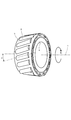
- FIG. 1 is an axial sectional view of the clutch device 1 according to the first embodiment of the present invention
- FIG. 2 is a perspective view of the inner ring 4 (input system rotating member) and the cage 9 showing the arrangement of the rollers 8.
- a mechanism for transmitting power from the inner ring 4 to the outer ring 10 is illustrated, and illustration of a thrust bearing and the like that receives an axial force is omitted. Further, illustration of a part of the teeth 12a, 13a formed on the first gear 12 and the second gear 13 respectively is omitted.
- the clutch device 1 includes an inner ring 4 as an input system rotating member, an outer ring 10 as an output system rotating member arranged on the outer peripheral side of the inner ring 4, and an inner ring 4 and an outer ring 10.
- a plurality of rollers 8 provided, a first gear 12 that rotates together with the outer ring 10, and a second gear 13 that engages with the first gear 12 are mainly provided.
- the inner ring 4 is a member having a function of transmitting the rotational power of the input shaft 2 to the outer ring 10, and an input raceway surface 4a forming a single leaf hyperboloid around the central axis o is formed on the outer peripheral surface.
- the inner ring 4 is restricted from rotating with respect to the input shaft 2 by the spline 4b, and is allowed to move in the axial direction with respect to the input shaft 2.
- the stoppers 5 and 6 are members for restricting the axial movement of the inner ring 4 exceeding a predetermined amount.
- the stoppers 5 and 6 are arranged on the outer periphery of the input shaft 2 at a predetermined interval from the axial end surface of the inner ring 4 and the inner ring 4.
- the inner ring 4 is urged to one axial side (the right side in FIG. 1) by a disc spring 7 disposed between the stopper 5 and the inner ring 4 so that the axial end surface is in contact with the stopper 6.
- the input shaft 2 has a camshaft 3 extending in the axial direction.
- the camshaft 3 is a member for causing the pin 3b to appear and retract on the outer periphery of the input shaft 2 by the cam surface 3a formed on the outer periphery by being moved in the axial direction by a drive device (not shown).
- the pin 3b is a member penetrating in the radial direction of the input shaft 2 and is pushed up by the cam surface 3a so that the tip protrudes from the outer periphery of the input shaft 2 to the inclined surface 4c formed on the inner peripheral surface of the inner ring 4. The tip is pressed.
- the outer ring 10 is a member having a function for transmitting the power of the input shaft 2 to the first gear 12 together with the inner ring 4, and an output raceway surface 10 a forming a single leaf rotation hyperboloid around the central axis o is formed on the inner peripheral surface.
- the outer ring 10 is configured to be rotatable relative to the inner ring 4 and to be relatively movable in the axial direction.
- the outer ring 10 is restricted from moving in the axial direction exceeding a predetermined amount by the flange 5 a and the stopper 6 protruding from the stopper 5.
- the stoppers 5 and 6 stop the axial movement of the inner ring 4 and the outer ring 10 at a fixed position when the roller 8 is engaged and screwed into the input raceway surface 4a and the output raceway surface 10a, and torque exceeding a certain level.
- a torque limiter function that prevents the roller 8 from being removed, and a function of preventing the roller 8 from coming off.
- the outer ring 10 is urged to the other side in the axial direction (left side in FIG. 1) by a disc spring 11 disposed between the stopper 6 and the outer ring 10 so that the end face in the axial direction contacts the flange 5a.
- the disc spring 11 is a member for biasing the outer ring 10 so as to widen the distance between the input raceway surface 4a and the output raceway surface 10a.
- the roller 8 is a member formed in a cylindrical shape, and is held between the input raceway surface 4a and the output raceway surface 10a by the cage 9.
- the cage 9 is a member for holding the rollers 8 at a distance from each other so that the rollers 8 can smoothly rotate without interfering with each other.
- a plurality of the rollers 8 are disposed in the circumferential direction of the input raceway surface 4a and the output raceway surface 10a with a predetermined angle ⁇ (for example, 15 °) from the plane including the central axis o, and the input raceway surface 4a and the output raceway surface 10a.
- the outer peripheral surface is arranged so as to be linearly contactable.
- the first gear 12 is a member for transmitting the power transmitted to the outer ring 10 to the second gear 13 to be engaged.
- the first gear 12 is formed or coupled to the outer peripheral surface of the outer ring 10 integrally with the outer ring 10, and The surface has a plurality of teeth 12a, and the teeth are formed so as to be non-parallel to the central axis o.
- the second gear 13 has a plurality of teeth 13a on the outer peripheral surface, and the tooth lines are formed so as to be non-parallel to the central axis o.
- the first gear 12 and the second gear 13 are formed as a pair of helical gears that engage with each other, and the axis of the rotary shaft 14 of the second gear 13 is arranged at a position different from the central axis o.
- the rotation shaft 14 of the second gear 13 is arranged in parallel with the central axis o.
- the second gear 13 may be a planetary gear mechanism in which a plurality of pinion gears are configured and a ring gear (internal gear) is disposed on the outer periphery of the second gear 13.
- the distance between the stoppers 5 and 6 and the flange 5a is such that the axial end surface of the inner ring 4 abuts against the stopper 6 and the axial end surface of the outer ring 10 abuts against the flange 5a by the biasing force of the disc springs 7 and 11.
- the outer peripheral surface of the roller 8 is set so as not to contact at least one of the input raceway surface 4a and the output raceway surface 10a. In this case, the rollers 8 cannot be engaged with the input raceway surface 4a and the output raceway surface 10a.
- the camshaft 3 is moved to one side in the axial direction (left side in FIG.
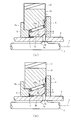
- FIGS. 3A is a cross-sectional side view of the clutch device 1 in which the input system rotating member (inner ring 4) is moved in the axial direction
- FIG. 3B is a side view of the clutch device 1 in which the rollers 8 are engaged
- 4A is a developed view of the input raceway surface 4a and the output raceway surface 10a
- FIG. 4B is a view of the input raceway surface 4a and the output raceway surface 10a in which the rollers 8 are engaged.
- It is a schematic diagram.
- the roller 8 and the outer ring 10 rotated by the torque of the inner ring 4 are illustrated by the roller 8 ′ and the outer ring 10 ′ (two-dot chain line).
- the roller 8 and the output raceway surface 10a are displaced (l and L) in the radial direction (up and down direction in FIG. 4B) by the rotation of the roller 8, and the output raceway surface 10a is elastically deformed in the radial direction by the displacement.
- Move in the direction of arrow K see FIG. 4A.
- the outer ring 10 rotates in the direction of the arrow Ro shown in FIG. 4A, and in the direction of the arrow C in the axial direction (the distance between the input track surface 4a and the output track surface 10a (hereinafter referred to as “track interval”)).
- Track interval the distance between the input track surface 4a and the output track surface 10a
- the outer ring 10 narrows the track interval against the biasing force of the disc spring 11 ( Move to the right side of FIG. Thereby, the rollers 8 are engaged with the input raceway surface 4a and the output raceway surface 10a, and the power is transmitted from the inner ring 4 to the outer ring 10.
- the clutch device 1 functions as a torque limiter.
- the inner ring 4 is relatively opposite to the outer ring 10 in the opposite direction (counter arrow Ri direction in FIG. 2).
- the inner ring 4 and the outer ring 10 move relative to each other in the direction away from each other in the axial direction due to a separation force (a force for moving the track interval in the direction of widening) due to the rotation of the roller 8. Since the movement of the inner ring 4 in the axial direction is regulated by the stopper 5 and the pin 3b, the outer ring 10 moves in the direction of increasing the track interval (left side in FIG. 3A) as shown in FIG. .
- the biasing force of the disc spring 11 assists the movement of the outer ring 4 in one axial direction (left side in FIG. 3A). Thereby, the engagement between the input raceway surface 4a and the output raceway surface 10a and the roller 8 is released, and the inner ring 4 and the outer ring 10 can be rotated relative to each other (free rotation).
- FIG. 5A is a schematic diagram showing a rotation direction and a thrust direction in meshing between the first gear 12 and the second gear 13.
- 5A shows the first gear 12 formed on the outer peripheral surface of the outer ring 10 and the second gear 13 engaged therewith, and the illustration of the inner ring 4, the roller 8, etc. is omitted, and the first gear 12 is omitted. Part of the teeth 12a and 13a formed on the first gear 12 and the second gear 13 are not shown.
- Axial forces in a fixed direction are generated in the second gear 13 (driven gear) and the first gear 12, respectively.
- the direction of the tooth traces of the first gear 12 and the second gear 13 is such that the direction of the axial force acting on the first gear 12 (the direction of arrow A in FIG. 5A) is that of the input raceway surface 4a and the output raceway surface 10a. It is set to be the same as the moving direction of the outer ring 10 in the axial direction when narrowing the interval (direction of arrow A in FIG. 5A).
- the axial component of the frictional force generated between the input raceway surface 4a and the output raceway surface 10a and the roller 8 is the inner ring 4 and outer ring 10 when the roller 8 is engaged with the input raceway surface 4a and the output raceway surface 10a.
- the pulling force in the axial direction is suppressed, and a predetermined torque cannot be transmitted from the inner ring 4 to the outer ring 10.
- the outer ring 10 is connected to the input raceway surface by the axial force caused by the reaction force of the second gear 13 in addition to the pulling force of the input raceway surface 4 a and the output raceway surface 10 a due to the rotation of the roller 8.
- Movement in the axial direction is promoted so as to narrow the distance between 4a and the output raceway surface 10a.
- the pulling force in the axial direction of the inner ring 4 and the outer ring 10 can be increased, so that the clutch device 1 can reliably transmit a predetermined torque.
- the friction between the tooth surfaces of the first gear 12 and the second gear 13 will be examined.
- the circumferential force N in the plane perpendicular to the axis is applied to the tooth surface of the first gear 12 by the reaction force of the second gear 13.
- the circumferential force N in the plane perpendicular to the axis also acts on the tooth surface of the second gear 13 that is the driven gear.
- the circumferential force N is decomposed into a tangential force F perpendicular to the central axis o and an axial force S parallel to the central axis o. If the torsion angle of the first gear 12 is ⁇ , the axial force S is expressed by the equation (1).
- the axis of the rotary shaft 14 of the second gear 13 is at a position different from the central axis o. Therefore, the second gear 13 is formed by an internal gear or the like concentric with the first gear 12. Compared to the rotation radius of the second gear 13 can be reduced. As a result, the clutch device 1 can be reduced in size and the structure can be simplified.
- the torque of the outer ring 10 is transmitted by the gears (the first gear 12 and the second gear 13), the torque is transmitted as compared with the case where the torque is transmitted by a ball spline, a pin or the like.
- the area of the contact surface can be increased.
- the surface pressure teeth surface pressure
- the durability of the portion (contact surface) to which torque is transmitted can be improved.
- first gear 12 and the second gear 13 are constituted by helical gears, the strength can be increased as compared with a spur gear of the same size, and the rotational power can be transmitted silently. Further, high-speed rotation can be transmitted, and the combination of the number of teeth of the first gear 12 and the second gear 13 is not limited, and the flexibility is excellent.
- the clutch device 101 inputs power from the second gear 113 to the first gear 112, and uses the outer ring 10 as an input system rotating member and the inner ring 4 as an output system rotating member.
- the first gear 112 (or the second gear 113). Is different from the first embodiment in that the twisting direction of the tooth streaks is different from the twisting direction of the first streaks of the first gear 12 (or the second gear 13) of the clutch device 1 in the first embodiment. .
- symbol is attached
- the present invention is not necessarily limited to this, and the axial end face of the inner ring 4 extends in the axial direction. It is possible to provide an extending portion (not shown) extending outward in the axial direction from the axial end surface of the first gear 12, 112 on the extending portion. By providing the second gears 13 and 113 that are engaged with the first gears 12 and 112, it is possible to achieve the same effects as the present embodiment.
- the case where the input raceway surface 4a and the output raceway surface 10a are formed as a single-leaf rotating hyperboloid and the cylindrical roller 8 is employed has been described.
- the input raceway surface 4a, the output raceway surface 10a, and the rollers 8 it is possible to employ the input raceway surface 4a, the output raceway surface 10a, and the rollers 8.
- the input raceway surface 4a and the output raceway surface 10a are formed as a single-leaf rotating hyperboloid and the roller 8 is conical
- the input raceway surface 4a or the output raceway surface 10a is cylindrical
- first gears 12 and 112 and the second gears 13 and 113 are constituted by a pair of helical gears (oblique gears)
- helical gears oblique gears
- other gears can be adopted as long as the teeth are formed so as to be non-parallel to the axis o and an axial force (thrust) is generated.
- other gears include bevel gears and screw gears.
- the present invention is not limited to this, and the second gears 13 and 113 are internal gears. By doing so, it is naturally possible to provide the axis of the rotation shaft 14 of the second gear 13 or 113 at the same position as the central axis o.
- the rotation shaft 14 of the second gears 13 and 113 is disposed at a position parallel to the central axis o.
- the present invention is not necessarily limited to this, and the positional relationship between the axis of the rotation shaft 14 of the second gears 13 and 113 and the central axis o is appropriately determined depending on the types of the first gears 12 and 112 and the second gears 13 and 113. It is possible to set.
- the axis of the rotation shaft 14 of the second gears 13 and 113 is disposed at a position intersecting the central axis o, and when screw gears are employed, the rotation shafts of the second gears 13 and 113 are arranged. 14 and the central axis o are arranged so as to be a discrepancy axis.
- first gears 12 and 112 are engaged with the second gears 13 and 113 and the rotation shaft 14 of the second gears 13 and 113 is used as the output shaft.
- a planetary gear mechanism is used in which the first gears 12 and 112 are sun gears, the second gears 13 and 113 are constituted by a plurality of pinion gears, and ring gears (internal gears) are arranged outside the second gears 13 and 113.
- ring gears internal gears
- the outer ring 10 is extended in the axial direction to provide first gears 12 and 112 (ring gears), the second gears 13 and 113 are constituted by a plurality of pinion gears, and a sun gear is provided inside the second gears 13 and 113.
- first gears 12 and 112 ring gears
- second gears 13 and 113 are constituted by a plurality of pinion gears
- a sun gear is provided inside the second gears 13 and 113.
- This planetary gear mechanism can adopt either a single pinion type or a double pinion type. In this case, the revolution of the pinion gear can be assigned to the output, and the rotation of the ring gear or sun gear can be assigned to the output.
- the camshaft 3 as a means for moving the inner ring 4 in the axial direction, the pin 3b that protrudes and protrudes by the cam surface 3a of the camshaft 3 and interferes with the inclined surface 4 of the inner ring 4, and the inner ring 4 in the axial direction.
- the present invention is not necessarily limited to this, and other moving means can naturally be employed. Examples of other moving means for moving the inner ring 4 or the outer ring 10 in the axial direction include known means such as a cylinder using fluid pressure and an electromagnet using magnetic force.
- the present invention is not necessarily limited to this, and other urging members are naturally adopted. Is possible. Examples of other urging members include a compression coil spring and a rubber-like elastic body.
- the disc spring 11 that biases the outer ring 10 is provided so as to widen the distance between the input raceway surface 4a and the output raceway surface 10a (moving the outer ring 10 toward the stopper 5).
- the outer ring 10 is moved to the stopper 5 side by the rotation of the roller 8 and the reaction force of the second gear 13, so that the disc spring 11 can be omitted.
Abstract
Provided is a clutch device capable of reliably transmitting predetermined torque. Power is transmitted from an outer ring (10) to a second gear (13) through a first gear (12). The teeth (12a) of the first gear (12) are formed so that the lines of the teeth (12a) are non-parallel to the center axis (o). The direction of axial force generated by the reaction force of the second gear (13) and acting on the first gear (12) is set to be the same as the direction of movement of the outer ring (10). When rollers (8) engage with raceway surfaces (4a, 10a) and power is transmitted from the first gear (12) to the second gear (13), the reaction force of the second gear (13) promotes the movement of the outer ring (10) in the axial direction. Predetermined torque can be reliably transmitted because axial pull-in force between an inner ring (4) and the outer ring (10) increases.
Description
本発明はクラッチ装置に関し、特に所定のトルクを確実に伝達できるクラッチ装置に関するものである。
The present invention relates to a clutch device, and more particularly to a clutch device capable of reliably transmitting a predetermined torque.
従来より、入力系回転部材および出力系回転部材の間に形成される軌道に複数のコロを配置したクラッチ装置が知られている(特許文献1)。特許文献1に開示されるクラッチ装置は、中心軸を含む面に対してコロが傾斜配置されると共に、出力系回転部材(外輪)が軸方向に移動自在に構成されている。出力系回転部材(外輪)に対して入力系回転部材(内輪)が所定方向に相対回転するときには、コロによる入力系回転部材および出力系回転部材の引き寄せ力(軌道間隔を狭める方向へ動かす力)により、出力系回転部材が軸方向に移動されてコロが係合し、出力系回転部材に動力が伝達される。一方、出力系回転部材に対して入力系回転部材が反対方向に相対回転するときには、コロによる入力系回転部材および出力系回転部材の引き離し力(軌道間隔を広げる方向へ動かす力)により、出力系回転部材が軸方向に移動されてコロが係合解除され、入力系回転部材および出力系回転部材は相対回転(自由回転)する。
Conventionally, there has been known a clutch device in which a plurality of rollers are arranged on a track formed between an input system rotating member and an output system rotating member (Patent Document 1). The clutch device disclosed in Patent Document 1 is configured such that a roller is inclined with respect to a surface including a central axis, and an output system rotating member (outer ring) is movable in the axial direction. When the input system rotating member (inner ring) rotates relative to the output system rotating member (outer ring) in a predetermined direction, the pulling force of the input system rotating member and the output system rotating member by the rollers (force to move in the direction of narrowing the track interval) Thus, the output system rotating member is moved in the axial direction, the rollers are engaged, and the power is transmitted to the output system rotating member. On the other hand, when the input system rotating member relatively rotates in the opposite direction with respect to the output system rotating member, the output system is driven by the separation force (the force that moves the orbital interval in the direction of widening the orbit interval) between the input system rotating member and the output system rotating member. The rotating member is moved in the axial direction, the roller is disengaged, and the input system rotating member and the output system rotating member rotate relative to each other (free rotation).
しかしながら上記従来の技術では、入力軌道面および出力軌道面にコロが係合するときには、入力軌道面および出力軌道面とコロとに生じる摩擦力の軸方向分力によって、入力系回転部材および出力系回転部材の軸方向の引き寄せ力が抑制される。そのため、入力軌道面および出力軌道面の間隔を十分に狭くすることができず、所定のトルクを伝達できなくなることがあるという問題があった。
However, in the above prior art, when the rollers are engaged with the input raceway surface and the output raceway surface, the input system rotating member and the output system are generated by the axial component of the frictional force generated between the input raceway surface, the output raceway surface and the roller. The pulling force in the axial direction of the rotating member is suppressed. For this reason, there is a problem in that the distance between the input raceway surface and the output raceway surface cannot be sufficiently narrowed, and a predetermined torque cannot be transmitted.
本発明は、上述した問題を解決するためになされたものであり、所定のトルクを確実に伝達できるクラッチ装置を提供することを目的としている。
The present invention has been made to solve the above-described problems, and an object thereof is to provide a clutch device that can reliably transmit a predetermined torque.
この目的を達成するために請求項1記載のクラッチ装置によれば、入力系回転部材に対して出力系回転部材が軸方向に相対移動可能に構成され、出力系回転部材の内周面または外周面の一方に出力軌道面が形成される。その出力軌道面に対向すると共に入力系回転部材の内周面または外周面の一方に入力軌道面が形成される。その入力軌道面と出力軌道面との間に複数のコロが介設され、そのコロは、入力系回転部材の中心軸を含む面から所定角度傾斜しているので、入力系回転部材を所定方向に回転させると、コロは入力軌道面および出力軌道面に案内されて自転しつつ中心軸の回りを公転する。そのコロの回転に案内されて、入力系回転部材および出力系回転部材は径方向に弾性変形しながら、軸方向に、入力軌道面と出力軌道面との間隔が小さくなる方向へ相対移動する。その結果、入力軌道面および出力軌道面にコロが係合して、入力系回転部材から出力系回転部材に動力が伝達される。
In order to achieve this object, the clutch device according to claim 1 is configured such that the output system rotating member is movable relative to the input system rotating member in the axial direction, and the inner peripheral surface or outer periphery of the output system rotating member. An output raceway surface is formed on one of the surfaces. The input raceway surface is formed on one of the inner circumferential surface and the outer circumferential surface of the input system rotating member while facing the output raceway surface. A plurality of rollers are interposed between the input raceway surface and the output raceway surface, and the rollers are inclined at a predetermined angle from the plane including the central axis of the input system rotation member. , The roller revolves around the central axis while rotating by being guided by the input raceway surface and the output raceway surface. Guided by the rotation of the rollers, the input system rotating member and the output system rotating member are relatively elastically deformed in the radial direction and relatively moved in the axial direction so that the distance between the input track surface and the output track surface is reduced. As a result, the rollers engage with the input raceway surface and the output raceway surface, and power is transmitted from the input system rotating member to the output system rotating member.
出力系回転部材に伝達された動力は出力系回転部材と一体に形成または結合される第1ギヤに伝達され、第1ギヤに係合する第2ギヤに伝達される。第1ギヤが入力系回転部材と一体に形成または結合されている場合には、第1ギヤと係合する第2ギヤから第1ギヤに動力が入力されると、入力系回転部材が回転する。第1ギヤは歯すじが中心軸に対して非平行となるように歯が形成されており、第2ギヤの反力によって第1ギヤに作用する軸方向力の向きは、入力軌道面および出力軌道面の間隔を狭めるときの軸方向における入力系回転部材または出力系回転部材の移動の向きと同一に設定されている。そのため、入力軌道面および出力軌道面にコロが係合して第1ギヤから第2ギヤへ動力が伝達されると、その第2ギヤの反力によって、入力系回転部材または出力系回転部材は、入力軌道面および出力軌道面の間隔を狭めるように軸方向への移動が促進される。これにより入力系回転部材および出力系回転部材の軸方向の引き寄せ力を増加させることができ、所定のトルクを確実に伝達できる効果がある。
The power transmitted to the output system rotating member is transmitted to the first gear formed or coupled integrally with the output system rotating member, and is transmitted to the second gear engaged with the first gear. When the first gear is integrally formed or coupled with the input system rotating member, when power is input from the second gear engaged with the first gear to the first gear, the input system rotating member rotates. . The first gear is formed with teeth that are not parallel to the central axis, and the direction of the axial force acting on the first gear by the reaction force of the second gear depends on the input raceway surface and the output. It is set to be the same as the direction of movement of the input system rotating member or the output system rotating member in the axial direction when the interval between the raceway surfaces is narrowed. Therefore, when the rollers are engaged with the input raceway surface and the output raceway surface and power is transmitted from the first gear to the second gear, the input system rotating member or the output system rotating member is caused by the reaction force of the second gear. Further, the movement in the axial direction is promoted so as to narrow the distance between the input raceway surface and the output raceway surface. Thereby, the pulling force in the axial direction of the input system rotating member and the output system rotating member can be increased, and there is an effect that a predetermined torque can be reliably transmitted.
請求項2記載のクラッチ装置によれば、第2ギヤの反力によって第1ギヤに作用する軸方向力の絶対値が、その軸方向力の反対方向に働く摩擦力であって第1ギヤ及び第2ギヤの歯面同士の摩擦による軸方向分力の絶対値より大きくなるように第1ギヤは設定されている。そのため、第1ギヤ及び第2ギヤの歯面同士の摩擦によって入力系回転部材および出力系回転部材の軸方向の引き寄せ力が抑制されることを防止できる。その結果、請求項1の効果に加え、所定のトルクを確実に伝達できる効果がある。
According to the clutch device according to claim 2, the absolute value of the axial force acting on the first gear by the reaction force of the second gear is a frictional force acting in the opposite direction of the axial force, and the first gear and The first gear is set to be larger than the absolute value of the axial component force caused by the friction between the tooth surfaces of the second gear. Therefore, it is possible to prevent the pulling force in the axial direction of the input system rotating member and the output system rotating member from being suppressed by the friction between the tooth surfaces of the first gear and the second gear. As a result, in addition to the effect of the first aspect, there is an effect that a predetermined torque can be reliably transmitted.
請求項3記載のクラッチ装置によれば、入力軌道面および出力軌道面とコロとが係合不能となる軸方向位置に移動手段により入力系回転部材または出力系回転部材が移動されるので、入力系回転部材から出力系回転部材への動力の伝達を遮断することができる。その結果、請求項1又は2の効果に加え、入力系回転部材から出力系回転部材へ動力を遮断可能に伝達できる効果がある。
According to the clutch device of the third aspect, the input system rotating member or the output system rotating member is moved by the moving means to the axial position where the input track surface and the output track surface cannot be engaged with the roller. Transmission of power from the system rotating member to the output system rotating member can be interrupted. As a result, in addition to the effect of the first or second aspect, there is an effect that power can be transmitted from the input system rotating member to the output system rotating member so as to be cut off.
請求項4記載のクラッチ装置によれば、第2ギヤの回転軸の軸線は中心軸と異なる位置にあるので、第2ギヤの回転半径を小さくすることができる。その結果、請求項1から3のいずれかの効果に加え、クラッチ装置を小型化できる効果がある。
According to the clutch device of the fourth aspect, since the axis of the rotating shaft of the second gear is at a position different from the central axis, the rotating radius of the second gear can be reduced. As a result, in addition to the effect of any one of claims 1 to 3, the clutch device can be downsized.
以下、本発明の好ましい実施の形態について添付図面を参照して説明する。図1は本発明の第1実施の形態におけるクラッチ装置1の軸方向断面図であり、図2はコロ8の配置を示す内輪4(入力系回転部材)及び保持器9の斜視図である。なお、図1では内輪4から外輪10へ動力を伝達する機構を図示し、軸方向力を受けるスラストベアリング等の図示を省略している。また、第1ギヤ12及び第2ギヤ13にそれぞれ形成された歯12a,13aの一部の図示を省略している。
Hereinafter, preferred embodiments of the present invention will be described with reference to the accompanying drawings. FIG. 1 is an axial sectional view of the clutch device 1 according to the first embodiment of the present invention, and FIG. 2 is a perspective view of the inner ring 4 (input system rotating member) and the cage 9 showing the arrangement of the rollers 8. In FIG. 1, a mechanism for transmitting power from the inner ring 4 to the outer ring 10 is illustrated, and illustration of a thrust bearing and the like that receives an axial force is omitted. Further, illustration of a part of the teeth 12a, 13a formed on the first gear 12 and the second gear 13 respectively is omitted.
図1に示すようにクラッチ装置1は、入力系回転部材としての内輪4と、その内輪4の外周側に配置される出力系回転部材としての外輪10と、内輪4及び外輪10の間に介設される複数のコロ8と、外輪10と共に回転する第1ギヤ12と、その第1ギヤ12に係合する第2ギヤ13とを主に備えて構成されている。
As shown in FIG. 1, the clutch device 1 includes an inner ring 4 as an input system rotating member, an outer ring 10 as an output system rotating member arranged on the outer peripheral side of the inner ring 4, and an inner ring 4 and an outer ring 10. A plurality of rollers 8 provided, a first gear 12 that rotates together with the outer ring 10, and a second gear 13 that engages with the first gear 12 are mainly provided.
内輪4は、入力軸2の回転動力を外輪10に伝達するための機能を担う部材であり、中心軸o回りの単葉回転双曲面をなす入力軌道面4aが外周面に形成されている。内輪4は、スプライン4bによって入力軸2に対して回転が規制される一方、入力軸2に対する軸方向の移動が許容されている。ストッパ5,6は、所定量を超える内輪4の軸方向の移動を規制するための部材であり、内輪4の軸方向端面と所定の間隔をあけて入力軸2の外周であって内輪4の軸方向端面の軸方向外側に突設されている。内輪4は、ストッパ5と内輪4との間に配設された皿ばね7によって、軸方向端面がストッパ6に当接するように軸方向の一方側(図1右側)に付勢されている。
The inner ring 4 is a member having a function of transmitting the rotational power of the input shaft 2 to the outer ring 10, and an input raceway surface 4a forming a single leaf hyperboloid around the central axis o is formed on the outer peripheral surface. The inner ring 4 is restricted from rotating with respect to the input shaft 2 by the spline 4b, and is allowed to move in the axial direction with respect to the input shaft 2. The stoppers 5 and 6 are members for restricting the axial movement of the inner ring 4 exceeding a predetermined amount. The stoppers 5 and 6 are arranged on the outer periphery of the input shaft 2 at a predetermined interval from the axial end surface of the inner ring 4 and the inner ring 4. It protrudes outward in the axial direction of the axial end surface. The inner ring 4 is urged to one axial side (the right side in FIG. 1) by a disc spring 7 disposed between the stopper 5 and the inner ring 4 so that the axial end surface is in contact with the stopper 6.
入力軸2は軸方向にカムシャフト3が貫設されている。カムシャフト3は、駆動装置(図示せず)によって軸方向に移動されることにより、外周に形成されたカム面3aによってピン3bを入力軸2の外周に出没させるための部材である。ピン3bは入力軸2の径方向に貫設される部材であり、カム面3aによって押し上げられて入力軸2の外周に先端が突出すると、内輪4の内周面に形成された傾斜面4cに先端が押し付けられる。内輪4の傾斜面4cにピン3bが押し付けられることによる内輪4の軸方向力は、皿ばね7の付勢力(軸方向力)より大きく設定されているので、皿ばね7の付勢力に抗して内輪4がストッパ5側(図1左側)に移動する。
The input shaft 2 has a camshaft 3 extending in the axial direction. The camshaft 3 is a member for causing the pin 3b to appear and retract on the outer periphery of the input shaft 2 by the cam surface 3a formed on the outer periphery by being moved in the axial direction by a drive device (not shown). The pin 3b is a member penetrating in the radial direction of the input shaft 2 and is pushed up by the cam surface 3a so that the tip protrudes from the outer periphery of the input shaft 2 to the inclined surface 4c formed on the inner peripheral surface of the inner ring 4. The tip is pressed. Since the axial force of the inner ring 4 due to the pin 3b being pressed against the inclined surface 4c of the inner ring 4 is set larger than the biasing force (axial force) of the disc spring 7, it resists the biasing force of the disc spring 7. The inner ring 4 moves to the stopper 5 side (left side in FIG. 1).
外輪10は、内輪4と共に入力軸2の動力を第1ギヤ12に伝達するための機能を担う部材であり、中心軸o回りの単葉回転双曲面をなす出力軌道面10aが内周面に形成されている。外輪10は、内輪4と相対回転可能かつ軸方向に相対移動可能に構成されている。外輪10は、ストッパ5に突設された鍔5a及びストッパ6によって、所定量を超える軸方向の移動が規制される。ストッパ5,6は、入力軌道面4a及び出力軌道面10aにコロ8が係合して捻じ込まれたときに、一定位置で内輪4及び外輪10の軸方向移動を停止させ、一定以上のトルクがかからないようにするトルクリミッタの機能と、コロ8の抜け出しを防止する機能とを有する。外輪10は、ストッパ6と外輪10との間に配設された皿ばね11によって、軸方向端面が鍔5aに当接するように軸方向の他方側(図1左側)に付勢されている。皿ばね11は、入力軌道面4a及び出力軌道面10aの間隔を広げるように外輪10を付勢するための部材である。
The outer ring 10 is a member having a function for transmitting the power of the input shaft 2 to the first gear 12 together with the inner ring 4, and an output raceway surface 10 a forming a single leaf rotation hyperboloid around the central axis o is formed on the inner peripheral surface. Has been. The outer ring 10 is configured to be rotatable relative to the inner ring 4 and to be relatively movable in the axial direction. The outer ring 10 is restricted from moving in the axial direction exceeding a predetermined amount by the flange 5 a and the stopper 6 protruding from the stopper 5. The stoppers 5 and 6 stop the axial movement of the inner ring 4 and the outer ring 10 at a fixed position when the roller 8 is engaged and screwed into the input raceway surface 4a and the output raceway surface 10a, and torque exceeding a certain level. A torque limiter function that prevents the roller 8 from being removed, and a function of preventing the roller 8 from coming off. The outer ring 10 is urged to the other side in the axial direction (left side in FIG. 1) by a disc spring 11 disposed between the stopper 6 and the outer ring 10 so that the end face in the axial direction contacts the flange 5a. The disc spring 11 is a member for biasing the outer ring 10 so as to widen the distance between the input raceway surface 4a and the output raceway surface 10a.
図2に示すように、コロ8は円筒状に形成される部材であり、保持器9によって入力軌道面4aと出力軌道面10aとの間に保持される。保持器9は、コロ8が相互に干渉することなく円滑に回転するように、互いに間隔をあけてコロ8を保持するための部材である。コロ8は、中心軸oを含む面から一定角度α(例えば15°)傾斜して入力軌道面4a及び出力軌道面10aの円周方向に複数配設され、入力軌道面4a及び出力軌道面10aに外周面が線状に接触可能に配置される。
2, the roller 8 is a member formed in a cylindrical shape, and is held between the input raceway surface 4a and the output raceway surface 10a by the cage 9. The cage 9 is a member for holding the rollers 8 at a distance from each other so that the rollers 8 can smoothly rotate without interfering with each other. A plurality of the rollers 8 are disposed in the circumferential direction of the input raceway surface 4a and the output raceway surface 10a with a predetermined angle α (for example, 15 °) from the plane including the central axis o, and the input raceway surface 4a and the output raceway surface 10a. The outer peripheral surface is arranged so as to be linearly contactable.
図1に戻って説明する。第1ギヤ12は、外輪10に伝達された動力を、係合する第2ギヤ13に伝達するための部材であり、外輪10の外周面に外輪10と一体に形成または結合されると共に、外周面に複数の歯12aを有し、その歯すじが中心軸oに対して非平行となるように形成されている。第2ギヤ13も同様に外周面に複数の歯13aを有し、その歯すじが中心軸oに対して非平行となるように形成されている。本実施の形態では、第1ギヤ12及び第2ギヤ13は、互いに係合する一対のヘリカルギヤとして形成されており、第2ギヤ13の回転軸14の軸線は中心軸oと異なる位置に配置されると共に、第2ギヤ13の回転軸14は中心軸oと平行に配置されている。なお、第2ギヤ13を複数のピニオンギヤで構成し、その第2ギヤ13の外周にリングギヤ(内歯車)を配置する遊星歯車機構とすることは可能である。
Referring back to FIG. The first gear 12 is a member for transmitting the power transmitted to the outer ring 10 to the second gear 13 to be engaged. The first gear 12 is formed or coupled to the outer peripheral surface of the outer ring 10 integrally with the outer ring 10, and The surface has a plurality of teeth 12a, and the teeth are formed so as to be non-parallel to the central axis o. Similarly, the second gear 13 has a plurality of teeth 13a on the outer peripheral surface, and the tooth lines are formed so as to be non-parallel to the central axis o. In the present embodiment, the first gear 12 and the second gear 13 are formed as a pair of helical gears that engage with each other, and the axis of the rotary shaft 14 of the second gear 13 is arranged at a position different from the central axis o. In addition, the rotation shaft 14 of the second gear 13 is arranged in parallel with the central axis o. The second gear 13 may be a planetary gear mechanism in which a plurality of pinion gears are configured and a ring gear (internal gear) is disposed on the outer periphery of the second gear 13.
ストッパ5,6及び鍔5aの間隔は、皿ばね7,11の付勢力によって内輪4の軸方向端面がストッパ6に当接されると共に外輪10の軸方向端面が鍔5aに当接される場合に、入力軌道面4a又は出力軌道面10aの少なくとも一方にコロ8の外周面が接触しないように設定されている。この場合は入力軌道面4a及び出力軌道面10aにコロ8は係合不能となる。これに対し、カムシャフト3を軸方向の一方側(図1左側)に移動させて皿ばね7の付勢力に抗して内輪4をストッパ5側に移動させた場合には、入力軌道面4a及び出力軌道面10aの間隔が狭くなり、入力軌道面4a及び出力軌道面10aにコロ8が線状に接触するように設定されている。
The distance between the stoppers 5 and 6 and the flange 5a is such that the axial end surface of the inner ring 4 abuts against the stopper 6 and the axial end surface of the outer ring 10 abuts against the flange 5a by the biasing force of the disc springs 7 and 11. In addition, the outer peripheral surface of the roller 8 is set so as not to contact at least one of the input raceway surface 4a and the output raceway surface 10a. In this case, the rollers 8 cannot be engaged with the input raceway surface 4a and the output raceway surface 10a. On the other hand, when the camshaft 3 is moved to one side in the axial direction (left side in FIG. 1) and the inner ring 4 is moved to the stopper 5 against the urging force of the disc spring 7, the input raceway surface 4a. Further, the interval between the output raceway surfaces 10a is narrowed, and the rollers 8 are set so as to come into linear contact with the input raceway surface 4a and the output raceway surface 10a.
以上のように構成されるクラッチ装置1について、図3及び図4を参照してその動作を説明する。図3(a)は入力系回転部材(内輪4)を軸方向に移動させたクラッチ装置1の片側断面図であり、図3(b)はコロ8が係合状態にあるクラッチ装置1の片側断面図であり、図4(a)は入力軌道面4a及び出力軌道面10aの展開図であり、図4(b)はコロ8が係合状態にある入力軌道面4a及び出力軌道面10aの模式図である。なお、図4(a)及び図4(b)では、内輪4のトルクによって回転したコロ8及び外輪10を、コロ8´及び外輪10´(二点鎖線)によって図示している。
The operation of the clutch device 1 configured as described above will be described with reference to FIGS. 3A is a cross-sectional side view of the clutch device 1 in which the input system rotating member (inner ring 4) is moved in the axial direction, and FIG. 3B is a side view of the clutch device 1 in which the rollers 8 are engaged. 4A is a developed view of the input raceway surface 4a and the output raceway surface 10a, and FIG. 4B is a view of the input raceway surface 4a and the output raceway surface 10a in which the rollers 8 are engaged. It is a schematic diagram. In FIGS. 4A and 4B, the roller 8 and the outer ring 10 rotated by the torque of the inner ring 4 are illustrated by the roller 8 ′ and the outer ring 10 ′ (two-dot chain line).
図3(a)に示すように、カムシャフト3を軸方向の一方側(図3(a)左側)に移動させ、ピン3bにより内輪4をストッパ5側に移動させた場合には、入力軌道面4a及び出力軌道面10aの間隔が狭くなり、入力軌道面4a及び出力軌道面10aにコロ8が線状に接触する。内輪4が一方向(図2及び図4(a)矢印Ri方向)に回転すると、図4(b)に示すようにコロ8が自転しながら(図4(b)時計回り)入力軌道面4aを公転する。コロ8の回転によってコロ8及び出力軌道面10aが径方向(図4(b)上下方向)に変位(l及びL)し、出力軌道面10aは、それらの変位によって径方向に弾性変形しながら矢印K方向(図4(a)参照)へ移動する。その結果、外輪10は、図4(a)に示す矢印Ro方向へ回転すると共に、軸方向における矢印C方向(入力軌道面4aと出力軌道面10aとの間隔(以下「軌道間隔」と称す)を狭める方向)へ相対移動する。軸方向における内輪4の移動はストッパ5及びピン3bによって規制されているので、図3(b)に示すように、外輪10が、皿ばね11の付勢力に抗して軌道間隔を狭める方向(図3(b)右側)に移動する。これにより、入力軌道面4a及び出力軌道面10aにコロ8が係合し内輪4から外輪10に動力が伝達される。
As shown in FIG. 3A, when the camshaft 3 is moved to one axial side (left side in FIG. 3A) and the inner ring 4 is moved to the stopper 5 side by the pin 3b, the input track The distance between the surface 4a and the output raceway surface 10a becomes narrow, and the rollers 8 come into linear contact with the input raceway surface 4a and the output raceway surface 10a. When the inner ring 4 rotates in one direction (direction of arrow Ri in FIGS. 2 and 4 (a)), the roller 8 rotates as shown in FIG. 4 (b) (clockwise in FIG. 4 (b)), and the input raceway surface 4a. Revolve. The roller 8 and the output raceway surface 10a are displaced (l and L) in the radial direction (up and down direction in FIG. 4B) by the rotation of the roller 8, and the output raceway surface 10a is elastically deformed in the radial direction by the displacement. Move in the direction of arrow K (see FIG. 4A). As a result, the outer ring 10 rotates in the direction of the arrow Ro shown in FIG. 4A, and in the direction of the arrow C in the axial direction (the distance between the input track surface 4a and the output track surface 10a (hereinafter referred to as “track interval”)). Move in the direction of narrowing). Since the movement of the inner ring 4 in the axial direction is regulated by the stopper 5 and the pin 3b, as shown in FIG. 3 (b), the outer ring 10 narrows the track interval against the biasing force of the disc spring 11 ( Move to the right side of FIG. Thereby, the rollers 8 are engaged with the input raceway surface 4a and the output raceway surface 10a, and the power is transmitted from the inner ring 4 to the outer ring 10.
なお、軸方向における外輪10の相対移動が所定の位置(ストッパ6の位置)で規制されると、それ以上は軸方向の軌道間隔は縮まらなく、外輪10の径方向の弾性変形が生じるので、その軌道間隔で伝達可能なトルク(所定値)より大きなトルクを伝達できなくなる。その結果、内輪4及び外輪10は所定値より大きなトルクで相対回転が可能となる。即ち、クラッチ装置1はトルクリミッタとしての機能を発揮する。
If the relative movement of the outer ring 10 in the axial direction is restricted at a predetermined position (the position of the stopper 6), the distance between the tracks in the axial direction is not further reduced, and the elastic deformation in the radial direction of the outer ring 10 occurs. A torque larger than the torque (predetermined value) that can be transmitted at the track interval cannot be transmitted. As a result, the inner ring 4 and the outer ring 10 can be relatively rotated with a torque larger than a predetermined value. That is, the clutch device 1 functions as a torque limiter.
次に、入力軌道面4a及び出力軌道面10aにコロ8が係合した状態において(図3(b)参照)、外輪10に対して内輪4が反対方向(図2反矢印Ri方向)に相対回転する場合には、コロ8の回転による引き離し力(軌道間隔を広げる方向へ動かす力)により、内輪4及び外輪10は軸方向において互いに離れる方向に相対移動する。軸方向における内輪4の移動はストッパ5及びピン3bによって規制されているので、図3(a)に示すように、外輪10が、軌道間隔を広げる方向(図3(a)左側)に移動する。皿ばね11の付勢力は、外輪4の軸方向の一方側(図3(a)左側)への移動を補助する。これにより、入力軌道面4a及び出力軌道面10aとコロ8との係合が解除され、内輪4及び外輪10は相対回転(自由回転)が可能となる。
Next, in a state in which the rollers 8 are engaged with the input raceway surface 4a and the output raceway surface 10a (see FIG. 3B), the inner ring 4 is relatively opposite to the outer ring 10 in the opposite direction (counter arrow Ri direction in FIG. 2). In the case of rotation, the inner ring 4 and the outer ring 10 move relative to each other in the direction away from each other in the axial direction due to a separation force (a force for moving the track interval in the direction of widening) due to the rotation of the roller 8. Since the movement of the inner ring 4 in the axial direction is regulated by the stopper 5 and the pin 3b, the outer ring 10 moves in the direction of increasing the track interval (left side in FIG. 3A) as shown in FIG. . The biasing force of the disc spring 11 assists the movement of the outer ring 4 in one axial direction (left side in FIG. 3A). Thereby, the engagement between the input raceway surface 4a and the output raceway surface 10a and the roller 8 is released, and the inner ring 4 and the outer ring 10 can be rotated relative to each other (free rotation).
なお、入力軌道面4a及び出力軌道面10aとコロ8との係合が解除された状態において(図3(a)参照)、カムシャフト3を軸方向の他方側(図3(a)右側)に移動させてピン3bによる傾斜面4cの押し付けを解除した場合には、皿ばね7の付勢力によって内輪4がストッパ6側に移動される。入力軌道面4a又は出力軌道面10aの少なくとも一方にコロ8が接触しなくなるので、コロ8は入力軌道面4a及び出力軌道面10aに係合不能となる。その結果、内輪4から外輪10への動力の伝達を遮断することができる。
In addition, in a state where the engagement between the input raceway surface 4a and the output raceway surface 10a and the roller 8 is released (see FIG. 3A), the camshaft 3 is placed on the other side in the axial direction (right side in FIG. 3A). When the pressing of the inclined surface 4c by the pin 3b is released, the inner ring 4 is moved to the stopper 6 side by the biasing force of the disc spring 7. Since the roller 8 does not contact at least one of the input raceway surface 4a and the output raceway surface 10a, the roller 8 cannot be engaged with the input raceway surface 4a and the output raceway surface 10a. As a result, transmission of power from the inner ring 4 to the outer ring 10 can be interrupted.
次に図5(a)を参照して、第1ギヤ12及び第2ギヤ13の回転方向と第1ギヤ12に作用する軸方向力(スラスト)について説明する。図5(a)は第1ギヤ12と第2ギヤ13との噛み合いにおける回転方向およびスラスト方向を示す模式図である。なお、図5(a)では外輪10の外周面に形成された第1ギヤ12と、それに係合する第2ギヤ13とを図示し、内輪4、コロ8等の図示を省略すると共に、第1ギヤ12及び第2ギヤ13にそれぞれ形成された歯12a,13aの一部の図示を省略している。
Next, the rotational direction of the first gear 12 and the second gear 13 and the axial force (thrust) acting on the first gear 12 will be described with reference to FIG. FIG. 5A is a schematic diagram showing a rotation direction and a thrust direction in meshing between the first gear 12 and the second gear 13. 5A shows the first gear 12 formed on the outer peripheral surface of the outer ring 10 and the second gear 13 engaged therewith, and the illustration of the inner ring 4, the roller 8, etc. is omitted, and the first gear 12 is omitted. Part of the teeth 12a and 13a formed on the first gear 12 and the second gear 13 are not shown.
入力軌道面4a及び出力軌道面10aにコロ8を線状に接触させた状態で、図5(a)に示すように、外輪10に対して内輪4を一方向(図5(a)矢印Ri方向)に相対回転させると、前述のように入力軌道面4a及び出力軌道面10aにコロ8が係合し内輪4から外輪10に動力が伝達される(矢印Roは外輪10の回転方向)。外輪10に伝達された動力によって第1ギヤ12が駆動されると(回転方向は矢印Ro方向)、第2ギヤ13及び回転軸14に回転が伝達されると共に(回転方向は矢印Rt方向)、第2ギヤ13(被動歯車)及び第1ギヤ12に、それぞれ一定方向(図5(a)矢印A方向及び矢印P方向)の軸方向力が発生する。第1ギヤ12及び第2ギヤ13の歯すじの方向は、第1ギヤ12に作用する軸方向力の向き(図5(a)矢印A方向)が、入力軌道面4a及び出力軌道面10aの間隔を狭めるときの軸方向における外輪10の移動方向(図5(a)矢印A方向)と同一になるように設定されている。
In a state where the rollers 8 are linearly contacted with the input raceway surface 4a and the output raceway surface 10a, as shown in FIG. 5 (a), the inner ring 4 is unidirectional with respect to the outer race 10 (FIG. 5 (a) arrow Ri. As described above, the rollers 8 are engaged with the input raceway surface 4a and the output raceway surface 10a as described above, and power is transmitted from the inner ring 4 to the outer ring 10 (the arrow Ro indicates the rotation direction of the outer ring 10). When the first gear 12 is driven by the power transmitted to the outer ring 10 (the rotation direction is the arrow Ro direction), the rotation is transmitted to the second gear 13 and the rotation shaft 14 (the rotation direction is the arrow Rt direction). Axial forces in a fixed direction (the direction of arrow A and the direction of arrow P in FIG. 5A) are generated in the second gear 13 (driven gear) and the first gear 12, respectively. The direction of the tooth traces of the first gear 12 and the second gear 13 is such that the direction of the axial force acting on the first gear 12 (the direction of arrow A in FIG. 5A) is that of the input raceway surface 4a and the output raceway surface 10a. It is set to be the same as the moving direction of the outer ring 10 in the axial direction when narrowing the interval (direction of arrow A in FIG. 5A).
ここで、入力軌道面4a及び出力軌道面10aとコロ8とに生じる摩擦力の軸方向分力は、入力軌道面4a及び出力軌道面10aにコロ8が係合するときの内輪4及び外輪10の軸方向の引き寄せ力を抑制し、内輪4から外輪10へ所定のトルクを伝達できない原因となる。これに対しクラッチ装置1によれば、コロ8の回転による入力軌道面4a及び出力軌道面10aの引き寄せ力に加え、第2ギヤ13の反力による軸方向力によって、外輪10は、入力軌道面4a及び出力軌道面10aの間隔を狭めるように軸方向への移動が促進される。その結果、内輪4及び外輪10の軸方向の引き寄せ力を増加させることができるので、クラッチ装置1は所定のトルクを確実に伝達できる。
Here, the axial component of the frictional force generated between the input raceway surface 4a and the output raceway surface 10a and the roller 8 is the inner ring 4 and outer ring 10 when the roller 8 is engaged with the input raceway surface 4a and the output raceway surface 10a. The pulling force in the axial direction is suppressed, and a predetermined torque cannot be transmitted from the inner ring 4 to the outer ring 10. On the other hand, according to the clutch device 1, the outer ring 10 is connected to the input raceway surface by the axial force caused by the reaction force of the second gear 13 in addition to the pulling force of the input raceway surface 4 a and the output raceway surface 10 a due to the rotation of the roller 8. Movement in the axial direction is promoted so as to narrow the distance between 4a and the output raceway surface 10a. As a result, the pulling force in the axial direction of the inner ring 4 and the outer ring 10 can be increased, so that the clutch device 1 can reliably transmit a predetermined torque.
一方、入力軌道面4a及び出力軌道面10aにコロ8が係合した状態において、外輪10に対して内輪4が反対方向(図5(a)反矢印Ri方向)に相対回転する場合には、第2ギヤ13が駆動歯車、第1ギヤ12が被動歯車となる。この場合には、第2ギヤ13及び第1ギヤ12にそれぞれ反対方向(図5(a)反矢印A方向および反矢印P方向)の軸方向力が発生する。この軸方向力は、第2ギヤ13が駆動歯車、第1ギヤ12が被動歯車となると同時に働くので、コロ8の回転による内輪4及び外輪10の引き離し力より外輪10に早く作用する。その結果、入力軌道面4aと出力軌道面10aとの間隔を早く広げることができるので、入力軌道面4a及び出力軌道面10aとコロ8との係合解除を素早く行うことができる。
On the other hand, in the state where the rollers 8 are engaged with the input raceway surface 4a and the output raceway surface 10a, when the inner race 4 rotates relative to the outer race 10 in the opposite direction (the opposite arrow Ri direction in FIG. 5A), The second gear 13 is a driving gear, and the first gear 12 is a driven gear. In this case, axial forces in opposite directions (in the opposite direction of arrow A and the opposite direction of arrow P in FIG. 5A) are generated in the second gear 13 and the first gear 12, respectively. The axial force acts on the outer ring 10 faster than the pulling force of the inner ring 4 and the outer ring 10 due to the rotation of the roller 8 because the second gear 13 acts as a driving gear and the first gear 12 becomes a driven gear. As a result, the distance between the input raceway surface 4a and the output raceway surface 10a can be increased quickly, so that the engagement between the input raceway surface 4a and the output raceway surface 10a and the roller 8 can be quickly performed.
また、内輪4及び外輪10が相対回転(自由回転)をするときには、コロ8の回転による入力軌道面4a及び出力軌道面10aの引き離し力に加え、第1ギヤ12及び第2ギヤ13による反対方向(図5(a)反矢印A方向)の軸方向力が外輪10に働く。その結果、コロ8の回転による引き離し力によって内輪4及び外輪10が離れる以上に、第1ギヤ12に働く軸方向力によって入力軌道面4a及び出力軌道面10aの間隔を広げることができる。これにより内輪4及び外輪10が相対回転(自由回転)をするときのトルクを減少できる。
Further, when the inner ring 4 and the outer ring 10 rotate relative to each other (free rotation), in addition to the separating force of the input raceway surface 4a and the output raceway surface 10a due to the rotation of the roller 8, the opposite directions by the first gear 12 and the second gear 13 are performed. An axial force in the direction indicated by the arrow A in FIG. As a result, the distance between the input raceway surface 4a and the output raceway surface 10a can be widened by the axial force acting on the first gear 12 more than the inner ring 4 and the outer ring 10 are separated by the pulling force due to the rotation of the roller 8. Thereby, the torque when the inner ring 4 and the outer ring 10 perform relative rotation (free rotation) can be reduced.
さらに図5(a)を参照して、第1ギヤ12及び第2ギヤ13の歯面同士の摩擦について検討する。第1ギヤ12を一方向(図5(a)矢印Ro方向)に回転した場合には、第2ギヤ13の反力によって第1ギヤ12の歯面に、軸直角平面における円周力Nが作用する。一方、被動歯車である第2ギヤ13の歯面にも、軸直角平面における円周力Nが作用する。円周力Nは、中心軸oと垂直方向の接線力F及び中心軸oと平行方向の軸方向力Sに分解される。第1ギヤ12のねじれ角をβとすれば、軸方向力Sは式(1)で表される。
Further, referring to FIG. 5A, the friction between the tooth surfaces of the first gear 12 and the second gear 13 will be examined. When the first gear 12 is rotated in one direction (the direction of the arrow Ro in FIG. 5A), the circumferential force N in the plane perpendicular to the axis is applied to the tooth surface of the first gear 12 by the reaction force of the second gear 13. Works. On the other hand, the circumferential force N in the plane perpendicular to the axis also acts on the tooth surface of the second gear 13 that is the driven gear. The circumferential force N is decomposed into a tangential force F perpendicular to the central axis o and an axial force S parallel to the central axis o. If the torsion angle of the first gear 12 is β, the axial force S is expressed by the equation (1).
S=N・sinβ …式(1)
また、第1ギヤ12及び第2ギヤ13の歯面同士の摩擦係数をμとすれば、第2ギヤ13の歯面による摩擦力の軸方向分力S´は式(2)で表される。 S = N · sin β Formula (1)
If the friction coefficient between the tooth surfaces of thefirst gear 12 and the second gear 13 is μ, the axial component force S ′ of the frictional force caused by the tooth surfaces of the second gear 13 is expressed by the following equation (2). .
また、第1ギヤ12及び第2ギヤ13の歯面同士の摩擦係数をμとすれば、第2ギヤ13の歯面による摩擦力の軸方向分力S´は式(2)で表される。 S = N · sin β Formula (1)
If the friction coefficient between the tooth surfaces of the
S´=μN・cosβ …式(2)
ここで、入力軌道面4a及び出力軌道面10aの間隔を狭めるように外輪10を軸方向(図5(a)矢印A方向)へ移動させるには、第2ギヤ13に対して第1ギヤ12を軸方向(図5(a)矢印A方向)に移動させることが必要である。そのためには摩擦力の軸方向分力S´の絶対値より軸方向力Sの絶対値が大きいこと、即ち式(3)が成立することが必要である。なお、S>0,S´>0なので、式(3)では絶対値記号を省略する。 S ′ = μN · cos β Formula (2)
Here, in order to move theouter ring 10 in the axial direction (the direction of arrow A in FIG. 5A) so as to narrow the distance between the input raceway surface 4a and the output raceway surface 10a, the first gear 12 with respect to the second gear 13. Must be moved in the axial direction (the direction of arrow A in FIG. 5A). For this purpose, it is necessary that the absolute value of the axial force S is larger than the absolute value of the axial component S ′ of the frictional force, that is, the expression (3) must be established. Since S> 0 and S ′> 0, the absolute value symbol is omitted in Equation (3).
ここで、入力軌道面4a及び出力軌道面10aの間隔を狭めるように外輪10を軸方向(図5(a)矢印A方向)へ移動させるには、第2ギヤ13に対して第1ギヤ12を軸方向(図5(a)矢印A方向)に移動させることが必要である。そのためには摩擦力の軸方向分力S´の絶対値より軸方向力Sの絶対値が大きいこと、即ち式(3)が成立することが必要である。なお、S>0,S´>0なので、式(3)では絶対値記号を省略する。 S ′ = μN · cos β Formula (2)
Here, in order to move the
S-S´>0 …式(3)
式(3)に式(1)及び式(2)を代入して解くと、式(4)が導かれる。 SS ′> 0 Formula (3)
When the equations (1) and (2) are substituted into the equation (3) and solved, the equation (4) is derived.
式(3)に式(1)及び式(2)を代入して解くと、式(4)が導かれる。 SS ′> 0 Formula (3)
When the equations (1) and (2) are substituted into the equation (3) and solved, the equation (4) is derived.
μ<tanβ …式(4)
式(4)に示すように第1ギヤ12及び第2ギヤ13の歯面同士の摩擦係数μと第1ギヤ12のねじれ角βとを設定すれば、第2ギヤ13に対して第1ギヤ12を軸方向(図5(a)矢印A方向)に移動させることができる。それに伴い入力軌道面4a及び出力軌道面10aの間隔を狭めるように外輪10を軸方向(図5(a)矢印A方向)へ移動させることができるので、第1ギヤ12及び第2ギヤ13の歯面同士の摩擦によって、内輪4及び外輪10の軸方向の引き寄せ力が抑制されることを防止できる。これによりクラッチ装置1は所定のトルクを確実に伝達できる。 μ <tan β Formula (4)
If the friction coefficient μ between the tooth surfaces of thefirst gear 12 and the second gear 13 and the torsion angle β of the first gear 12 are set as shown in the equation (4), the first gear with respect to the second gear 13 is set. 12 can be moved in the axial direction (direction of arrow A in FIG. 5A). Accordingly, the outer ring 10 can be moved in the axial direction (in the direction of arrow A in FIG. 5A) so as to narrow the distance between the input raceway surface 4a and the output raceway surface 10a, so that the first gear 12 and the second gear 13 It is possible to prevent the pulling force in the axial direction of the inner ring 4 and the outer ring 10 from being suppressed by the friction between the tooth surfaces. Thereby, the clutch apparatus 1 can transmit predetermined torque reliably.
式(4)に示すように第1ギヤ12及び第2ギヤ13の歯面同士の摩擦係数μと第1ギヤ12のねじれ角βとを設定すれば、第2ギヤ13に対して第1ギヤ12を軸方向(図5(a)矢印A方向)に移動させることができる。それに伴い入力軌道面4a及び出力軌道面10aの間隔を狭めるように外輪10を軸方向(図5(a)矢印A方向)へ移動させることができるので、第1ギヤ12及び第2ギヤ13の歯面同士の摩擦によって、内輪4及び外輪10の軸方向の引き寄せ力が抑制されることを防止できる。これによりクラッチ装置1は所定のトルクを確実に伝達できる。 μ <tan β Formula (4)
If the friction coefficient μ between the tooth surfaces of the
また、クラッチ装置1によれば、第2ギヤ13の回転軸14の軸線は中心軸oと異なる位置にあるので、第1ギヤ12と同心状の内歯車等によって第2ギヤ13を形成する場合と比較して、第2ギヤ13の回転半径を小さくすることができる。その結果、クラッチ装置1を小型化できると共に構造を簡素化できる。
Further, according to the clutch device 1, the axis of the rotary shaft 14 of the second gear 13 is at a position different from the central axis o. Therefore, the second gear 13 is formed by an internal gear or the like concentric with the first gear 12. Compared to the rotation radius of the second gear 13 can be reduced. As a result, the clutch device 1 can be reduced in size and the structure can be simplified.
また、外輪10(出力系回転部材)のトルクはギヤ(第1ギヤ12及び第2ギヤ13)によって伝達されるので、ボールスプラインやピン等によってトルクを伝達する場合と比較して、トルクが伝達される接触面の面積を大きくできる。その結果、面圧(歯面圧)を低下させることができ、トルクが伝達される部分(接触面)の耐久性を向上できる。
Further, since the torque of the outer ring 10 (output system rotating member) is transmitted by the gears (the first gear 12 and the second gear 13), the torque is transmitted as compared with the case where the torque is transmitted by a ball spline, a pin or the like. The area of the contact surface can be increased. As a result, the surface pressure (tooth surface pressure) can be reduced, and the durability of the portion (contact surface) to which torque is transmitted can be improved.
また、第1ギヤ12及び第2ギヤ13はヘリカルギヤによって構成されているので、同じ大きさの平歯車に比べて強度を大きくできると共に、静かに回転動力を伝達できる。また、高速回転を伝達可能であると共に、第1ギヤ12及び第2ギヤ13の歯数の組み合わせに制限がなく自在性に優れる。
Further, since the first gear 12 and the second gear 13 are constituted by helical gears, the strength can be increased as compared with a spur gear of the same size, and the rotational power can be transmitted silently. Further, high-speed rotation can be transmitted, and the combination of the number of teeth of the first gear 12 and the second gear 13 is not limited, and the flexibility is excellent.
次に図5(b)を参照して、第2実施の形態におけるクラッチ装置101について説明する。クラッチ装置101は、第2ギヤ113から第1ギヤ112に動力を入力し、外輪10を入力系回転部材、内輪4を出力系回転部材とする点、第1ギヤ112(又は第2ギヤ113)の歯すじのねじれ方向を、第1実施の形態におけるクラッチ装置1の第1ギヤ12(又は第2ギヤ13)の歯すじのねじれ方向と異ならせている点が第1実施の形態と相違する。なお、第1実施の形態と同一の部分については、同一の符号を付して以下の説明を省略する。
Next, the clutch device 101 according to the second embodiment will be described with reference to FIG. The clutch device 101 inputs power from the second gear 113 to the first gear 112, and uses the outer ring 10 as an input system rotating member and the inner ring 4 as an output system rotating member. The first gear 112 (or the second gear 113). Is different from the first embodiment in that the twisting direction of the tooth streaks is different from the twisting direction of the first streaks of the first gear 12 (or the second gear 13) of the clutch device 1 in the first embodiment. . In addition, about the part same as 1st Embodiment, the same code | symbol is attached | subjected and the following description is abbreviate | omitted.
図5(b)に示すように回転軸14及び第2ギヤ113を矢印Rt方向に回転すると、第1ギヤ112が矢印Ri方向に被動され、外輪10が矢印Riに回転する。内輪4及び外輪10にコロ8が係合すると、軸102から矢印Roの回転動力が出力される。
When the rotating shaft 14 and the second gear 113 are rotated in the direction of the arrow Rt as shown in FIG. 5B, the first gear 112 is driven in the direction of the arrow Ri, and the outer ring 10 is rotated in the direction of the arrow Ri. When the roller 8 is engaged with the inner ring 4 and the outer ring 10, the rotational power indicated by the arrow Ro is output from the shaft 102.
第1ギヤ112が矢印Ri方向に被動されるときは、第2ギヤ113(歯113a)の反力によって、第1ギヤ112(歯112a)の歯面に軸直角平面における円周力Nが作用する。これにより、第1ギヤ112及び外輪10に軸方向力S(矢印A方向)が発生する。クラッチ装置101もクラッチ装置1と同様に、第1ギヤ112に作用する軸方向力Sの向き(矢印A方向)が、軌道間隔を狭めるときの軸方向における外輪10の移動方向と同一になるように、第1ギヤ112及び第2ギヤ113の歯すじのねじれ方向が設定されている。
When the first gear 112 is driven in the direction of the arrow Ri, the circumferential force N in the plane perpendicular to the axis acts on the tooth surface of the first gear 112 (tooth 112a) by the reaction force of the second gear 113 (tooth 113a). To do. As a result, an axial force S (in the direction of arrow A) is generated in the first gear 112 and the outer ring 10. Similarly to the clutch device 1, the direction of the axial force S acting on the first gear 112 (in the direction of arrow A) is also the same as the direction of movement of the outer ring 10 in the axial direction when narrowing the track interval. Further, the twist direction of the tooth traces of the first gear 112 and the second gear 113 is set.
以上、実施の形態に基づき本発明を説明したが、本発明は上記実施の形態に何ら限定されるものではなく、本発明の趣旨を逸脱しない範囲内で種々の改良変形が可能であることは容易に推察できるものである。例えば、上記実施の形態で挙げた数値(例えば、各構成の数量や寸法等)は一例であり、他の数値を採用することは当然可能である。
The present invention has been described above based on the embodiments. However, the present invention is not limited to the above embodiments, and various improvements and modifications can be made without departing from the spirit of the present invention. It can be easily guessed. For example, the numerical values (for example, the number and size of each component) given in the above embodiment are merely examples, and other numerical values can naturally be adopted.
上記実施の形態では、外輪10の外周に第1ギヤ12,112を設ける場合について説明したが、必ずしもこれに限られるものではなく、内輪4の軸方向端面を軸方向に延設して外輪10の軸方向端面より軸方向外側に延びる延設部(図示せず)を設け、その延設部に第1ギヤ12,112を設けることは可能である。その第1ギヤ12,112に係合する第2ギヤ13,113を設けることにより、本実施の形態と同様の作用効果を実現できる。
In the above embodiment, the case where the first gears 12 and 112 are provided on the outer periphery of the outer ring 10 has been described. However, the present invention is not necessarily limited to this, and the axial end face of the inner ring 4 extends in the axial direction. It is possible to provide an extending portion (not shown) extending outward in the axial direction from the axial end surface of the first gear 12, 112 on the extending portion. By providing the second gears 13 and 113 that are engaged with the first gears 12 and 112, it is possible to achieve the same effects as the present embodiment.
上記実施の形態では、入力軌道面4a及び出力軌道面10aを単葉回転双曲面で形成し、円筒状のコロ8を採用する場合について説明したが、必ずしもこれに限られるものではなく、他の形態における入力軌道面4a、出力軌道面10a及びコロ8を採用することは当然可能である。他の形態としては、例えば入力軌道面4a及び出力軌道面10aを単葉回転双曲面で形成しコロ8を円錐状とするもの、入力軌道面4a又は出力軌道面10aを円筒状としたり、コロ8を鼓状、太鼓状や円筒状としたりするもの等が挙げられる。
In the above-described embodiment, the case where the input raceway surface 4a and the output raceway surface 10a are formed as a single-leaf rotating hyperboloid and the cylindrical roller 8 is employed has been described. Of course, it is possible to employ the input raceway surface 4a, the output raceway surface 10a, and the rollers 8. As other forms, for example, the input raceway surface 4a and the output raceway surface 10a are formed as a single-leaf rotating hyperboloid and the roller 8 is conical, the input raceway surface 4a or the output raceway surface 10a is cylindrical, Can be a drum shape, a drum shape, or a cylindrical shape.
上記実施の形態では、第1ギヤ12,112及び第2ギヤ13,113を一対のヘリカルギヤ(斜歯ギヤ)で構成する場合について説明したが、必ずしもこれに限られるものではなく、歯すじが中心軸oと非平行となるように歯を形成し軸方向力(スラスト)が発生するものであれば、他のギヤを採用することは当然可能である。他のギヤとしては、例えば、かさ歯車、ねじ歯車等を挙げることができる。
In the above embodiment, the case where the first gears 12 and 112 and the second gears 13 and 113 are constituted by a pair of helical gears (oblique gears) has been described. Of course, other gears can be adopted as long as the teeth are formed so as to be non-parallel to the axis o and an axial force (thrust) is generated. Examples of other gears include bevel gears and screw gears.
上記実施の形態では、第2ギヤ13,113の回転軸14を中心軸oと異なる位置に設ける場合について説明したが、必ずしもこれに限られるものではなく、第2ギヤ13,113を内歯車とすることによって、第2ギヤ13,113の回転軸14の軸線を中心軸oと同じ位置に設けることは当然可能である。
In the above embodiment, the case where the rotation shaft 14 of the second gears 13 and 113 is provided at a position different from the central axis o has been described. However, the present invention is not limited to this, and the second gears 13 and 113 are internal gears. By doing so, it is naturally possible to provide the axis of the rotation shaft 14 of the second gear 13 or 113 at the same position as the central axis o.
上記実施の形態では、第1ギヤ12,112及び第2ギヤ13,113を一対のヘリカルギヤで構成したので、第2ギヤ13,113の回転軸14を中心軸oと平行な位置に配置する場合について説明した。しかし、必ずしもこれに限られるものではなく、第2ギヤ13,113の回転軸14の軸線と中心軸oとの位置関係は、第1ギヤ12,112及び第2ギヤ13,113の種類によって適宜設定することが可能である。例えば、かさ歯車を採用した場合には第2ギヤ13,113の回転軸14の軸線を中心軸oと交わる位置に配置し、ねじ歯車を採用した場合には第2ギヤ13,113の回転軸14と中心軸oとを食い違い軸となるように配置する。
In the above embodiment, since the first gears 12 and 112 and the second gears 13 and 113 are configured by a pair of helical gears, the rotation shaft 14 of the second gears 13 and 113 is disposed at a position parallel to the central axis o. Explained. However, the present invention is not necessarily limited to this, and the positional relationship between the axis of the rotation shaft 14 of the second gears 13 and 113 and the central axis o is appropriately determined depending on the types of the first gears 12 and 112 and the second gears 13 and 113. It is possible to set. For example, when bevel gears are employed, the axis of the rotation shaft 14 of the second gears 13 and 113 is disposed at a position intersecting the central axis o, and when screw gears are employed, the rotation shafts of the second gears 13 and 113 are arranged. 14 and the central axis o are arranged so as to be a discrepancy axis.
上記実施の形態では、第1ギヤ12,112に第2ギヤ13,113を係合させ、その第2ギヤ13,113の回転軸14を出力軸とする場合について説明したが、必ずしもこれに限られるものではない。例えば、第1ギヤ12,112をサンギヤとすると共に第2ギヤ13,113を複数のピニオンギヤで構成し、その第2ギヤ13,113の外側にリングギヤ(内歯車)を配置した遊星歯車機構を採用することは当然可能である。また、外輪10を軸方向に延設して第1ギヤ12,112(リングギヤ)を設け、第2ギヤ13,113を複数のピニオンギヤで構成し、その第2ギヤ13,113の内側にサンギヤを配置した遊星歯車機構を採用することも可能である。この遊星歯車機構は、シングルピニオン式、ダブルピニオン式のいずれを採用することも可能である。この場合、ピニオンギヤの公転を出力に割り当てたり、リングギヤやサンギヤの回転を出力に割り当てたりすることができる。
In the above embodiment, the case where the first gears 12 and 112 are engaged with the second gears 13 and 113 and the rotation shaft 14 of the second gears 13 and 113 is used as the output shaft has been described. Is not something For example, a planetary gear mechanism is used in which the first gears 12 and 112 are sun gears, the second gears 13 and 113 are constituted by a plurality of pinion gears, and ring gears (internal gears) are arranged outside the second gears 13 and 113. Of course it is possible to do. Further, the outer ring 10 is extended in the axial direction to provide first gears 12 and 112 (ring gears), the second gears 13 and 113 are constituted by a plurality of pinion gears, and a sun gear is provided inside the second gears 13 and 113. It is also possible to employ an arranged planetary gear mechanism. This planetary gear mechanism can adopt either a single pinion type or a double pinion type. In this case, the revolution of the pinion gear can be assigned to the output, and the rotation of the ring gear or sun gear can be assigned to the output.
上記実施の形態では、内輪4及び外輪10とコロ8とを係合不能にするため、カムを利用して内輪4を軸方向に移動させる場合について説明したが、必ずしもこれに限られるものではなく、外輪10を軸方向に移動させる手段を採用することによって、内輪4及び外輪10とコロ8とを係合不能にすることは当然可能である。
In the above embodiment, in order to make the inner ring 4 and the outer ring 10 and the roller 8 unengageable, the case where the inner ring 4 is moved in the axial direction using a cam has been described. However, the present invention is not necessarily limited thereto. Of course, by adopting a means for moving the outer ring 10 in the axial direction, it is possible to make the inner ring 4 and the outer ring 10 and the roller 8 unengageable.
上記実施の形態では、内輪4を軸方向に移動させる手段としてカムシャフト3と、そのカムシャフト3のカム面3aによって出没し内輪4の傾斜面4と干渉するピン3bと、軸方向に内輪4を付勢する皿ばね7とを備える場合について説明したが、必ずしもこれに限られるものではなく、他の移動手段を採用することは当然可能である。内輪4又は外輪10を軸方向に移動させる他の移動手段としては、例えば、流体圧を利用するシリンダ、磁力を利用する電磁石等の公知の手段を挙げることが可能である。
In the above-described embodiment, the camshaft 3 as a means for moving the inner ring 4 in the axial direction, the pin 3b that protrudes and protrudes by the cam surface 3a of the camshaft 3 and interferes with the inclined surface 4 of the inner ring 4, and the inner ring 4 in the axial direction. However, the present invention is not necessarily limited to this, and other moving means can naturally be employed. Examples of other moving means for moving the inner ring 4 or the outer ring 10 in the axial direction include known means such as a cylinder using fluid pressure and an electromagnet using magnetic force.
上記実施の形態では、皿ばね7,11によって内輪4や外輪10を軸方向に付勢する場合について説明したが、必ずしもこれに限られるものではなく、他の付勢部材を採用することは当然可能である。他の付勢部材としては、例えば圧縮コイルばね、ゴム状弾性体等が挙げられる。
In the above embodiment, the case where the inner ring 4 and the outer ring 10 are urged in the axial direction by the disc springs 7 and 11 has been described. However, the present invention is not necessarily limited to this, and other urging members are naturally adopted. Is possible. Examples of other urging members include a compression coil spring and a rubber-like elastic body.
上記実施の形態では、入力軌道面4a及び出力軌道面10aの間隔を広げる(ストッパ5側に外輪10を移動させる)ように外輪10を付勢する皿ばね11を設けているが、外輪10及び内輪4が相対回転するときには、コロ8の回転および第2ギヤ13の反力によって外輪10がストッパ5側に動かされるので、皿ばね11を省略することは可能である。
In the above embodiment, the disc spring 11 that biases the outer ring 10 is provided so as to widen the distance between the input raceway surface 4a and the output raceway surface 10a (moving the outer ring 10 toward the stopper 5). When the inner ring 4 rotates relatively, the outer ring 10 is moved to the stopper 5 side by the rotation of the roller 8 and the reaction force of the second gear 13, so that the disc spring 11 can be omitted.
1,101 クラッチ装置
3 カムシャフト(移動手段の一部)
4 内輪(入力系回転部材または出力系回転部材)
4a 入力軌道面、出力軌道面
7 皿ばね(移動手段の一部)
8 コロ
10 外輪(出力系回転部材または入力系回転部材)
10a 出力軌道面、入力軌道面
12,112 第1ギヤ
12a,112a 歯
13,113 第2ギヤ
14 回転軸
o 中心軸 1,101Clutch device 3 Camshaft (part of moving means)
4 Inner ring (input system rotating member or output system rotating member)
4a Input raceway surface,output raceway surface 7 Disc spring (part of moving means)
8Roller 10 Outer ring (output system rotating member or input system rotating member)
10a Output raceway surface, input raceway surface 12, 112 First gear 12a, 112a Teeth 13, 113 Second gear 14 Rotating axis o Center axis
3 カムシャフト(移動手段の一部)
4 内輪(入力系回転部材または出力系回転部材)
4a 入力軌道面、出力軌道面
7 皿ばね(移動手段の一部)
8 コロ
10 外輪(出力系回転部材または入力系回転部材)
10a 出力軌道面、入力軌道面
12,112 第1ギヤ
12a,112a 歯
13,113 第2ギヤ
14 回転軸
o 中心軸 1,101
4 Inner ring (input system rotating member or output system rotating member)
4a Input raceway surface,
8
10a Output raceway surface,
Claims (4)
- 入力系回転部材およびその入力系回転部材に対して軸方向に相対移動可能に構成された出力系回転部材と、
その出力系回転部材の内周面または外周面の一方に形成された出力軌道面と、
その出力軌道面に対向すると共に前記入力系回転部材の内周面または外周面の一方に形成された入力軌道面と、
その入力軌道面と前記出力軌道面との間に前記入力系回転部材の中心軸を含む面から所定角度傾斜させて介設された複数のコロと、
前記入力系回転部材または前記出力系回転部材と一体に形成または結合されると共に、前記中心軸に対して歯すじが非平行となるように歯が形成された第1ギヤと、
その第1ギヤに係合する第2ギヤとを備え、
その第2ギヤの反力によって前記第1ギヤに作用する軸方向力の向きは、前記入力軌道面および前記出力軌道面の間隔を狭めるときの軸方向における前記入力系回転部材または前記出力系回転部材の移動の向きと同一に設定されていることを特徴とするクラッチ装置。 An input system rotating member and an output system rotating member configured to be relatively movable in the axial direction with respect to the input system rotating member;
An output raceway surface formed on one of the inner peripheral surface or the outer peripheral surface of the output system rotating member;
An input raceway surface facing the output raceway surface and formed on one of the inner peripheral surface or the outer peripheral surface of the input system rotating member;
A plurality of rollers interposed between the input raceway surface and the output raceway surface by being inclined at a predetermined angle from a plane including the central axis of the input system rotating member;
A first gear formed or coupled integrally with the input system rotating member or the output system rotating member, and having teeth formed so that the tooth traces are not parallel to the central axis;
A second gear engaged with the first gear,
The direction of the axial force acting on the first gear by the reaction force of the second gear is such that the input system rotating member or the output system rotation in the axial direction when the distance between the input raceway surface and the output raceway surface is narrowed. A clutch device characterized by being set to have the same direction of movement of the member. - 前記第1ギヤは、前記第2ギヤの反力によって前記第1ギヤに作用する軸方向力の絶対値が、前記第1ギヤ及び前記第2ギヤの歯面同士の摩擦によって前記軸方向力と反対方向に働く摩擦力の軸方向分力の絶対値より大きくなるように設定されていることを特徴とする請求項1記載のクラッチ装置。 In the first gear, the absolute value of the axial force acting on the first gear due to the reaction force of the second gear is different from the axial force due to the friction between the tooth surfaces of the first gear and the second gear. The clutch device according to claim 1, wherein the clutch device is set to be larger than an absolute value of an axial component of a frictional force acting in an opposite direction.
- 前記入力軌道面および前記出力軌道面と前記コロとが係合不能となる軸方向位置に前記入力系回転部材または前記出力系回転部材を移動させる移動手段を備えていることを特徴とする請求項1又は2に記載のクラッチ装置。 The moving means for moving the input system rotating member or the output system rotating member to an axial position where the input track surface, the output track surface and the roller cannot be engaged with each other. The clutch device according to 1 or 2.
- 前記第2ギヤの回転軸の軸線は、前記中心軸と異なる位置にあることを特徴とする請求項1から3のいずれかに記載のクラッチ装置。 The clutch device according to any one of claims 1 to 3, wherein an axis of a rotation shaft of the second gear is at a position different from the central axis.
Priority Applications (2)
| Application Number | Priority Date | Filing Date | Title |
|---|---|---|---|
| EP13768380.1A EP2833013B1 (en) | 2012-03-28 | 2013-03-26 | Clutch device |
| US14/388,750 US9523398B2 (en) | 2012-03-28 | 2013-03-26 | Clutch device |
Applications Claiming Priority (2)
| Application Number | Priority Date | Filing Date | Title |
|---|---|---|---|
| JP2012-073099 | 2012-03-28 | ||
| JP2012073099A JP5897951B2 (en) | 2012-03-28 | 2012-03-28 | Clutch device |
Publications (1)
| Publication Number | Publication Date |
|---|---|
| WO2013146776A1 true WO2013146776A1 (en) | 2013-10-03 |
Family
ID=49260027
Family Applications (1)
| Application Number | Title | Priority Date | Filing Date |
|---|---|---|---|
| PCT/JP2013/058766 WO2013146776A1 (en) | 2012-03-28 | 2013-03-26 | Clutch device |
Country Status (4)
| Country | Link |
|---|---|
| US (1) | US9523398B2 (en) |
| EP (1) | EP2833013B1 (en) |
| JP (1) | JP5897951B2 (en) |
| WO (1) | WO2013146776A1 (en) |
Cited By (1)
| Publication number | Priority date | Publication date | Assignee | Title |
|---|---|---|---|---|
| WO2017154133A1 (en) * | 2016-03-09 | 2017-09-14 | 株式会社ユニバンス | Power transmission apparatus |
Families Citing this family (4)
| Publication number | Priority date | Publication date | Assignee | Title |
|---|---|---|---|---|
| WO2018216185A1 (en) * | 2017-05-26 | 2018-11-29 | 株式会社ユニバンス | Power transmission device |
| EP3884182A1 (en) | 2018-11-19 | 2021-09-29 | ABB Schweiz AG | Planetary gear train, gearbox and industrial robot |
| DE102021111056B3 (en) * | 2021-04-29 | 2022-06-23 | Voith Patent Gmbh | Wave switch for electric drive trains |
| CN113958626B (en) * | 2021-10-21 | 2023-10-31 | 中国北方车辆研究所 | Unidirectional spiral coupling suitable for speed changer |
Citations (5)
| Publication number | Priority date | Publication date | Assignee | Title |
|---|---|---|---|---|
| JPH03204418A (en) * | 1990-01-05 | 1991-09-06 | Shiro Sawa | Fluid friction transmitting force restricting apparatus |
| JPH03244832A (en) * | 1990-02-19 | 1991-10-31 | Meihou Koeki Kk | Clutch bearing |
| JPH03260422A (en) * | 1990-03-08 | 1991-11-20 | Kubota Corp | Rolling clutch |
| JPH06173976A (en) | 1992-04-22 | 1994-06-21 | T H K Mento Kenkyusho:Kk | On/off-clutch |
| JPH084792A (en) * | 1994-06-14 | 1996-01-09 | Thk Ment Kenkyusho:Kk | On-off type torque limiter |
Family Cites Families (13)
| Publication number | Priority date | Publication date | Assignee | Title |
|---|---|---|---|---|
| US5211273A (en) * | 1986-01-22 | 1993-05-18 | Hybo Science, Inc. | Axial thrust clutch/bearing/freewheel |
| US5035309A (en) * | 1989-05-08 | 1991-07-30 | Nobuo Takada | Rolling-contact bearing type clutch |
| GB2241755B (en) | 1990-03-08 | 1994-01-12 | Kubota Kk | Conical roller type clutch apparatus |
| JP2938966B2 (en) * | 1990-11-21 | 1999-08-25 | テイエチケー株式会社 | Rolling bearing clutch |
| JPH0893799A (en) * | 1994-09-29 | 1996-04-09 | Mitsubishi Electric Corp | Overrunning clutch |
| JPH08338503A (en) * | 1995-06-12 | 1996-12-24 | Ebara Corp | Power transmission device |
| JP3443483B2 (en) * | 1995-06-12 | 2003-09-02 | 株式会社荏原製作所 | Rolling bearing clutch |
| JP3444807B2 (en) * | 1999-02-12 | 2003-09-08 | 建治 三村 | Differential device |
| JP3364603B2 (en) * | 1999-06-25 | 2003-01-08 | 建治 三村 | FRICTION CLUTCH, AUTOMATIC TRANSMISSION OF AUTOMOBILE, CONTINUOUS TRANSMISSION OF AUTOMOBILE USING THE SAME, AUTOMOBILE POWER DISTRIBUTION DEVICE, AND MOTORCYCLE POWER TRANSMISSION DEVICE |
| GB2354814A (en) * | 1999-09-29 | 2001-04-04 | Mechadyne Internat Plc | Phase change mechanism |
| JP2004138125A (en) * | 2002-10-16 | 2004-05-13 | Ntn Corp | Clutch |
| EP1746300A4 (en) * | 2004-04-30 | 2011-08-17 | Hitachi Ltd | Clutch structure of mechanical automatic transmission |
| DE102008060959A1 (en) | 2008-12-06 | 2010-06-10 | Neumayer Tekfor Holding Gmbh | Shaft switch and gearbox with at least one shaft switch |
-
2012
- 2012-03-28 JP JP2012073099A patent/JP5897951B2/en not_active Expired - Fee Related
-
2013
- 2013-03-26 WO PCT/JP2013/058766 patent/WO2013146776A1/en active Application Filing
- 2013-03-26 US US14/388,750 patent/US9523398B2/en active Active
- 2013-03-26 EP EP13768380.1A patent/EP2833013B1/en not_active Not-in-force
Patent Citations (5)
| Publication number | Priority date | Publication date | Assignee | Title |
|---|---|---|---|---|
| JPH03204418A (en) * | 1990-01-05 | 1991-09-06 | Shiro Sawa | Fluid friction transmitting force restricting apparatus |
| JPH03244832A (en) * | 1990-02-19 | 1991-10-31 | Meihou Koeki Kk | Clutch bearing |
| JPH03260422A (en) * | 1990-03-08 | 1991-11-20 | Kubota Corp | Rolling clutch |
| JPH06173976A (en) | 1992-04-22 | 1994-06-21 | T H K Mento Kenkyusho:Kk | On/off-clutch |
| JPH084792A (en) * | 1994-06-14 | 1996-01-09 | Thk Ment Kenkyusho:Kk | On-off type torque limiter |
Non-Patent Citations (1)
| Title |
|---|
| See also references of EP2833013A4 |
Cited By (1)
| Publication number | Priority date | Publication date | Assignee | Title |
|---|---|---|---|---|
| WO2017154133A1 (en) * | 2016-03-09 | 2017-09-14 | 株式会社ユニバンス | Power transmission apparatus |
Also Published As
| Publication number | Publication date |
|---|---|
| JP2013204667A (en) | 2013-10-07 |
| US9523398B2 (en) | 2016-12-20 |
| EP2833013A1 (en) | 2015-02-04 |
| US20150135874A1 (en) | 2015-05-21 |
| JP5897951B2 (en) | 2016-04-06 |
| EP2833013B1 (en) | 2016-12-28 |
| EP2833013A4 (en) | 2015-12-30 |
Similar Documents
| Publication | Publication Date | Title |
|---|---|---|
| JP5897951B2 (en) | Clutch device | |
| EP2585729B1 (en) | Improvements in and relating to anti back-drive couplings | |
| US9377060B1 (en) | Ball ramp actuator | |
| JP6194436B1 (en) | Rotation transmission device combined with planetary gear mechanism | |
| WO2014034648A1 (en) | Electric direct-acting actuator and electric disc brake device | |
| EP2615323A1 (en) | Electric direct-acting actuator and electric disc brake device | |
| JP2014152857A (en) | Free-type bidirectional clutch | |
| US20130256083A1 (en) | Driving force transmission apparatus, and four-wheel-drive vehicle including the driving force transmission apparatus | |
| JP6082530B2 (en) | transmission | |
| JP2004340367A (en) | Hypoid gear device | |
| KR102262294B1 (en) | Gear transmission device | |
| JP6058597B2 (en) | Free type two-way clutch using pin | |
| JP2015021526A (en) | Free-type bidirectional clutch | |
| JP4930771B2 (en) | Electric power steering device | |
| JP6939230B2 (en) | Seal mechanism | |
| WO2017061306A1 (en) | Reverse input cutoff clutch | |
| JP2017003104A (en) | Reverse input block clutch | |
| JP6297355B2 (en) | Reverse input prevention clutch | |
| WO2012140400A1 (en) | A drive coupling | |
| US11690736B2 (en) | Anti-back drive device | |
| US10006494B2 (en) | Torque transmission mechanism | |
| WO2016199750A1 (en) | Reverse input blocking clutch | |
| JP2018204785A (en) | Clutch, drive transmission, and image forming device | |
| WO2016190206A1 (en) | Reverse input blocking clutch | |
| JP2016008701A (en) | Electrically-driven linear motion actuator and electrically-driven brake device |
Legal Events
| Date | Code | Title | Description |
|---|---|---|---|
| 121 | Ep: the epo has been informed by wipo that ep was designated in this application |
Ref document number: 13768380 Country of ref document: EP Kind code of ref document: A1 |
|
| NENP | Non-entry into the national phase |
Ref country code: DE |
|
| REEP | Request for entry into the european phase |
Ref document number: 2013768380 Country of ref document: EP |
|
| WWE | Wipo information: entry into national phase |
Ref document number: 2013768380 Country of ref document: EP |
|
| WWE | Wipo information: entry into national phase |
Ref document number: 14388750 Country of ref document: US |