WO2013146744A1 - 撮像装置 - Google Patents
撮像装置 Download PDFInfo
- Publication number
- WO2013146744A1 WO2013146744A1 PCT/JP2013/058705 JP2013058705W WO2013146744A1 WO 2013146744 A1 WO2013146744 A1 WO 2013146744A1 JP 2013058705 W JP2013058705 W JP 2013058705W WO 2013146744 A1 WO2013146744 A1 WO 2013146744A1
- Authority
- WO
- WIPO (PCT)
- Prior art keywords
- unit
- fixed pattern
- imaging
- video
- vehicle
- Prior art date
- Legal status (The legal status is an assumption and is not a legal conclusion. Google has not performed a legal analysis and makes no representation as to the accuracy of the status listed.)
- Ceased
Links
Images


Classifications
-
- H—ELECTRICITY
- H04—ELECTRIC COMMUNICATION TECHNIQUE
- H04N—PICTORIAL COMMUNICATION, e.g. TELEVISION
- H04N17/00—Diagnosis, testing or measuring for television systems or their details
- H04N17/002—Diagnosis, testing or measuring for television systems or their details for television cameras
-
- H—ELECTRICITY
- H04—ELECTRIC COMMUNICATION TECHNIQUE
- H04N—PICTORIAL COMMUNICATION, e.g. TELEVISION
- H04N23/00—Cameras or camera modules comprising electronic image sensors; Control thereof
- H04N23/60—Control of cameras or camera modules
Definitions
- the present invention relates to an imaging device that images a field of view, and in particular, includes an imaging unit that images a field of view, and a control unit that is electrically connected to the imaging unit and executes control according to the captured image.
- the present invention also relates to an imaging apparatus having a function capable of determining an abnormality in the electrical connection.
- Imaging devices that capture images according to light incident from the field of view are used in various fields.
- an imaging apparatus including an imaging unit and a control unit that is electrically connected to the imaging unit and executes control according to the captured video is known.
- this type of imaging apparatus has been increasingly installed in vehicles. For example, it has been proposed to capture the periphery of a vehicle, perform image processing on the captured image, and reflect the processing result on the traveling of the vehicle.
- Patent Document 1 discloses an imaging device that images the periphery of a vehicle. This imaging device is in a driving state that is estimated to be not nighttime, such as when the headlamp is off, and when the level of the signal output by the imaging unit (the brightness of the captured image) is a predetermined value or less, It is configured to determine that an abnormality has occurred in the signal.
- Patent Document 1 there is a problem when an abnormality is determined by comparing the signal level corresponding to the image captured by the imaging unit with a predetermined value.
- the predetermined value must be set to be considerably low in consideration of variations in characteristics of the imaging unit and individual differences depending on whether or not the headlamp is turned on. For this reason, for example, a minor abnormality may not be determined by the technique of Patent Document 1, such as when a part of a parallel cable that sends an image captured by the imaging unit as a digital signal to the control unit is disconnected.
- the electrical connection is light. It is desirable to be able to determine abnormalities.
- An imaging apparatus includes: an imaging unit that acquires an image; and an imaging unit that includes a fixed pattern output unit that outputs a preset fixed pattern; the video acquired by the imaging unit; The control unit to which the fixed pattern output from the fixed pattern output means is input, the imaging unit and the control unit are electrically connected, and the video and the fixed pattern are electrically connected from the imaging unit to the control unit. And a communication path.
- the control unit compares the fixed pattern with a predetermined pattern prepared in advance according to the fixed pattern output by the fixed pattern output unit, a control unit that executes control of the application according to the video.
- an abnormality determining means for determining an abnormality in electrical connection of the path.
- control unit can execute control according to the video imaged by the imaging unit.
- abnormality determination means can determine the abnormality of the electrical connection as follows.
- the fixed pattern output by the fixed pattern output means is a preset fixed pattern. For this reason, if there is no abnormality in the path that electrically connects the imaging unit and the control unit, the same fixed pattern should always be input to the control unit as an electrical signal. Therefore, the abnormality determination unit compares the predetermined pattern prepared in advance according to the fixed pattern output from the fixed pattern output unit with the fixed pattern input as the electric signal, thereby determining the electrical connection. Even minor abnormalities can be judged.
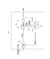
- FIG. 1 is a block diagram showing the configuration of a camera system to which the present invention is applied.
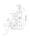
- FIG. 2 is a block diagram showing the configuration of the camera of the camera system.
- FIG. 3 is a flowchart showing processing by the microcomputer of the camera system.
- FIG. 4 is an explanatory diagram showing the principle of the processing.
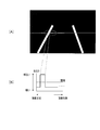
- FIG. 5 is an explanatory diagram showing an application example of the processing.
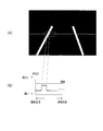
- FIG. 6 is an explanatory diagram showing a state when the camera system is abnormal according to the application example.
- FIG. 1 shows a schematic configuration of an in-vehicle camera system CM as an imaging apparatus.
- the camera system CM includes an in-vehicle camera 1 that acquires an image of a visual field directed to the outside of the vehicle as shown in FIG.
- the camera 1 includes an image sensor 10 made of a one-chip IC and a lens 11.
- the camera 1 is provided, for example, in the vicinity of the base of the room mirror at the center upper portion of the windshield FT of the vehicle, and is arranged with the lens 11, that is, with the field of view directed obliquely downward and forward.
- the image sensor 10 includes a light receiving unit 13, a controller 15, a buffer 17, and a test pattern generating unit 19.
- the light receiving unit 13 includes phototransistors and AD converters arranged in an array. In response to an instruction from the controller 15, the light receiving unit 13 sends data (electrical signal) corresponding to an image outside the vehicle imaged through the lens 11 to the test pattern generation unit 19 through the buffer 17.
- the test pattern generator 19 performs various processes such as gamma correction on the transmitted data, and transmits the data to a microcomputer (hereinafter referred to as a microcomputer) 20 provided outside the camera 1. This transmission is performed via an 8-bit or 16-bit parallel cable CB.
- a microcomputer hereinafter referred to as a microcomputer 20 provided outside the camera 1. This transmission is performed via an 8-bit or 16-bit parallel cable CB.
- a thick broken line DL shown in FIG. 2 indicates the flow of the data.
- the test pattern generator 19 also has a function of outputting data corresponding to various adjustment test patterns (an example of a fixed pattern). Therefore, the test pattern is also transmitted to the microcomputer 20 via the parallel cable CB.
- the microcomputer 20 transmits a test pattern request to the controller 15 when requesting the transmission of the test pattern. In response to this, the request RQ is transmitted to the test pattern generator 19 via the light receiver 13. For this reason, the test pattern generator 19 transmits the test pattern to the microcomputer 20 in response to the request.
- test pattern generator 19 when transmitting this test pattern, is configured to interrupt the processing / transmission of imaging data. That is, the test pattern generation unit 19 is configured to selectively execute test pattern transmission and imaging data processing / transmission.
- test pattern generation unit 19 causes the processing / transmission of the processing of the imaging data to be executed in parallel as the process behind the output of the test pattern. May be. Further, both data may be transmitted in parallel by parallel processing such as time division.
- the camera system CM includes a power supply 30 that supplies power (camera power) to the image sensor 10 and causes the image sensor 10 to perform the above-described imaging operation.
- the power source 30 is supplied with electric power from a vehicle power source such as a battery.
- the microcomputer 20 is configured to output a control signal for switching on / off of the camera power to the power source 30.
- FIG. 3 is a flowchart showing processing executed by the microcomputer 20 when the ignition switch of the vehicle is turned on and the power supply 30 is also turned on. This process is executed by a CPU built in the microcomputer 20 based on a program stored in a ROM that is also built in the microcomputer 20.
- step S1 the image sensor 10 is requested to output a test pattern.
- step S3 it is determined as follows whether or not the test pattern transmitted from the test pattern generator 19 of the image sensor 10 is normal in response to the request.
- FIG. 4A is an explanatory diagram showing an example of a test pattern.
- this test pattern represents a test pattern that gradually becomes brighter as it goes from the left to the right of the video.
- the pixel value (brightness for each pixel) increases at a constant rate from the left to the right. It shows a change that increases. Specifically, for example, if the data is represented by an 8-bit binary number, the pixel value increases from “00000000” to “11111111” at a constant rate from the left end to the right end.
- step S3 it is determined whether or not the data corresponding to the received test pattern is a normal value according to such a rule (an example of a prescribed pattern) registered in advance in the ROM of the microcomputer 20. Is done.
- a rule an example of a prescribed pattern registered in advance in the ROM of the microcomputer 20.
- the pixel value may be compared by a method such as CRC (cyclic redundancy check).
- step S5 an instruction is given to continue the operation of various applications using the camera 1, which is started at the same time as the ignition switch is turned on, and the process is temporarily ended.
- step S7 an instruction is given to stop the operation of the application, and the camera power is turned off to the power supply 30. Instructed, the process is temporarily terminated.
- the correctness / inaccuracy of the pixel value can be inspected based on information of each bit.
- it can also be detected from the last one bit of information that is usually difficult to detect. Therefore, minor abnormalities such as a case where only one line of the parallel cable CB is disconnected or a short circuit between data lines can be detected well. This makes it possible to determine whether the entire imaging data is accurate or inaccurate as well as the entire pixel value of one line. This is due to the fact that the test pattern is transmitted through the same parallel cable CB as the imaging data.
- the operation of the application can be stopped and the camera power can be turned off. For this reason, it is possible to prevent the operation of the application from being executed or continued based on data that does not accurately reflect the video imaged through the camera 1.
- a white line departure alarm that determines whether or not the vehicle has deviated from the white line on the road and generates an alarm when the vehicle deviates.
- the road surface having a white line is imaged as shown in FIG. Therefore, as shown by a solid line in FIG. 5A, when one pixel is extracted in the horizontal direction at the center in the vertical direction of the video and the pixel value is viewed, the pixel value in the portion surrounded by the broken line in FIG. A change like (B) is shown. That is, the pixel value rapidly rises at the location corresponding to the white line and exceeds the threshold value.
- the microcomputer 20 recognizes the white line on the road in this way, and issues an alarm when the vehicle deviates from the white line.
- the video corresponding to the data may be as shown in FIG. 6, for example.
- the pixel value does not rise sufficiently even at the location corresponding to the white line and does not exceed the threshold value.
- the white line is hatched to indicate that the pixel value is lower than that of FIG.
- step S3 no
- step S7 the control of the white line departure alarm is stopped.
- the driver may be notified through the display device in the driver's seat, and further, the camera 1 may be notified of the abnormality.
- the driver unlike the case where a video corresponding to the data transmitted to the microcomputer 20 is displayed on a display or the like, the driver cannot find an abnormality in the data transmitted to the microcomputer 20. Therefore, if the present embodiment is applied to control without display processing as described above, the effect of the embodiment that an abnormality such as disconnection can be detected as described above becomes more useful.
- the light receiving unit 13 is executed by the microcomputer 20
- the test pattern generator 19 is executed by the test pattern output unit
- the image sensor 10 is executed by the image pickup unit
- the microcomputer 20 is executed by the microcomputer 20
- This process corresponds to the control means
- the process of step S3 executed by the microcomputer 20 corresponds to the abnormality determination means.
- this invention is not limited to the structure of the said embodiment at all, It can implement with a various form in the range which does not deviate from the summary of this invention.
- the processing of FIG. 3 does not have to be performed when the power is turned on, and may be executed once every several seconds.
- the fixed pattern is not limited to the gradient as shown in FIG. 4A, and may be another fixed pattern.
- applications include auto high beam control that allows a high beam when there is no preceding vehicle, and collision avoidance control that automatically brakes when approaching the preceding vehicle. Is also applicable.
- the present invention can also be applied to consumer devices other than vehicles.
- the fixed pattern and the prescribed pattern are compared by CRC in the above embodiment, a checksum may be used.
- the load on the microcomputer 20 is smaller than comparing individual pixel values, and the accuracy can be improved compared to using a checksum.
- the prescribed pattern to be compared does not necessarily have to be the same as the fixed pattern, and may be the complement of the pixel value of the fixed pattern, for example.
- test pattern output request in step S1 of FIG. 3 can be omitted if the test pattern is output periodically or automatically when the power is turned on.
- electrically connected in the present invention is not limited to connection via a parallel cable, and may be connection via a conductor on a printed wiring board or a conductive portion in an IC.
Landscapes
- Engineering & Computer Science (AREA)
- Multimedia (AREA)
- Signal Processing (AREA)
- Health & Medical Sciences (AREA)
- Biomedical Technology (AREA)
- General Health & Medical Sciences (AREA)
- Studio Devices (AREA)
- Closed-Circuit Television Systems (AREA)
- Traffic Control Systems (AREA)
- Testing, Inspecting, Measuring Of Stereoscopic Televisions And Televisions (AREA)
Priority Applications (3)
| Application Number | Priority Date | Filing Date | Title |
|---|---|---|---|
| DE201311001782 DE112013001782T5 (de) | 2012-03-30 | 2013-03-26 | Bildgebungsvorrichtung |
| CN201380017966.XA CN104247416B (zh) | 2012-03-30 | 2013-03-26 | 图像拾取设备 |
| US14/389,085 US9241157B2 (en) | 2012-03-30 | 2013-03-26 | Imaging apparatus |
Applications Claiming Priority (2)
| Application Number | Priority Date | Filing Date | Title |
|---|---|---|---|
| JP2012081605A JP6171264B2 (ja) | 2012-03-30 | 2012-03-30 | 撮像装置 |
| JP2012-081605 | 2012-03-30 |
Publications (1)
| Publication Number | Publication Date |
|---|---|
| WO2013146744A1 true WO2013146744A1 (ja) | 2013-10-03 |
Family
ID=49259995
Family Applications (1)
| Application Number | Title | Priority Date | Filing Date |
|---|---|---|---|
| PCT/JP2013/058705 Ceased WO2013146744A1 (ja) | 2012-03-30 | 2013-03-26 | 撮像装置 |
Country Status (5)
| Country | Link |
|---|---|
| US (1) | US9241157B2 (enExample) |
| JP (1) | JP6171264B2 (enExample) |
| CN (1) | CN104247416B (enExample) |
| DE (1) | DE112013001782T5 (enExample) |
| WO (1) | WO2013146744A1 (enExample) |
Cited By (1)
| Publication number | Priority date | Publication date | Assignee | Title |
|---|---|---|---|---|
| CN104980731A (zh) * | 2014-04-01 | 2015-10-14 | 株式会社电装 | 用于基于捕获图像执行处理的控制设备和控制系统 |
Families Citing this family (1)
| Publication number | Priority date | Publication date | Assignee | Title |
|---|---|---|---|---|
| JP2018042141A (ja) | 2016-09-08 | 2018-03-15 | 株式会社デンソー | 撮像装置 |
Citations (4)
| Publication number | Priority date | Publication date | Assignee | Title |
|---|---|---|---|---|
| JPH10108222A (ja) * | 1996-09-30 | 1998-04-24 | Matsushita Electric Works Ltd | 画像処理装置の検査方法 |
| JP2006211235A (ja) * | 2005-01-27 | 2006-08-10 | Mitsubishi Electric Corp | 撮像装置の接続試験システム |
| JP2006235285A (ja) * | 2005-02-25 | 2006-09-07 | Fuji Photo Film Co Ltd | デジタルカメラ及びレンズユニット及びレンズユニットの判別制御方法及びレンズユニットの劣化判定方法 |
| JP2009157087A (ja) * | 2007-12-26 | 2009-07-16 | Denso Corp | 露出制御装置及び露出制御プログラム |
Family Cites Families (12)
| Publication number | Priority date | Publication date | Assignee | Title |
|---|---|---|---|---|
| CA2049616C (en) * | 1991-01-22 | 2000-04-04 | Jacob Soiferman | Contactless test method and system for testing printed circuit boards |
| US5414343A (en) * | 1992-07-28 | 1995-05-09 | Samuel J. Flaherty | Permanently installed cable system with integrated multi-cable tester |
| JP3586123B2 (ja) * | 1998-12-07 | 2004-11-10 | 三菱電機株式会社 | チャネルチェックテストシステム |
| JP3659110B2 (ja) | 2000-01-21 | 2005-06-15 | 三菱自動車工業株式会社 | 車載用画像処理装置 |
| US6694463B2 (en) * | 2001-01-16 | 2004-02-17 | Atmel Corporation | Input/output continuity test mode circuit |
| WO2005096218A1 (en) | 2004-03-31 | 2005-10-13 | Canon Kabushiki Kaisha | Imaging system performance measurement |
| JP2005073296A (ja) | 2004-10-27 | 2005-03-17 | Mitsubishi Electric Corp | 車両用カメラの露光制御装置 |
| JP2008283431A (ja) | 2007-05-10 | 2008-11-20 | Matsushita Electric Ind Co Ltd | 画像処理装置 |
| JP5207823B2 (ja) | 2008-05-14 | 2013-06-12 | アルパイン株式会社 | 画像判断装置および画像判断方法 |
| JP2010136823A (ja) | 2008-12-10 | 2010-06-24 | Olympus Medical Systems Corp | 信号処理装置、撮像装置及び撮像システム |
| CN101521832B (zh) * | 2009-03-16 | 2011-04-06 | 广州杰赛科技股份有限公司 | 电视网络信号质量监控系统及监控方法 |
| JP5338760B2 (ja) * | 2010-07-12 | 2013-11-13 | 株式会社デンソー | 画像表示装置および画像表示装置の検査方法 |
-
2012
- 2012-03-30 JP JP2012081605A patent/JP6171264B2/ja not_active Expired - Fee Related
-
2013
- 2013-03-26 DE DE201311001782 patent/DE112013001782T5/de not_active Withdrawn
- 2013-03-26 CN CN201380017966.XA patent/CN104247416B/zh not_active Expired - Fee Related
- 2013-03-26 US US14/389,085 patent/US9241157B2/en not_active Expired - Fee Related
- 2013-03-26 WO PCT/JP2013/058705 patent/WO2013146744A1/ja not_active Ceased
Patent Citations (4)
| Publication number | Priority date | Publication date | Assignee | Title |
|---|---|---|---|---|
| JPH10108222A (ja) * | 1996-09-30 | 1998-04-24 | Matsushita Electric Works Ltd | 画像処理装置の検査方法 |
| JP2006211235A (ja) * | 2005-01-27 | 2006-08-10 | Mitsubishi Electric Corp | 撮像装置の接続試験システム |
| JP2006235285A (ja) * | 2005-02-25 | 2006-09-07 | Fuji Photo Film Co Ltd | デジタルカメラ及びレンズユニット及びレンズユニットの判別制御方法及びレンズユニットの劣化判定方法 |
| JP2009157087A (ja) * | 2007-12-26 | 2009-07-16 | Denso Corp | 露出制御装置及び露出制御プログラム |
Cited By (2)
| Publication number | Priority date | Publication date | Assignee | Title |
|---|---|---|---|---|
| CN104980731A (zh) * | 2014-04-01 | 2015-10-14 | 株式会社电装 | 用于基于捕获图像执行处理的控制设备和控制系统 |
| US10489889B2 (en) | 2014-04-01 | 2019-11-26 | Denso Corporation | Control apparatus and control system for performing process based on captured image |
Also Published As
| Publication number | Publication date |
|---|---|
| DE112013001782T5 (de) | 2015-02-26 |
| US20150085140A1 (en) | 2015-03-26 |
| JP2013211756A (ja) | 2013-10-10 |
| CN104247416A (zh) | 2014-12-24 |
| CN104247416B (zh) | 2016-08-24 |
| US9241157B2 (en) | 2016-01-19 |
| JP6171264B2 (ja) | 2017-08-02 |
Similar Documents
| Publication | Publication Date | Title |
|---|---|---|
| US10176594B2 (en) | Progressive in-vehicle camera calibrator, image generator, in-vehicle camera calibration method, and image generation method | |
| JP5851035B2 (ja) | 回路装置、及び、センサ信号の妥当性検査方法 | |
| US7746091B2 (en) | Sensor apparatus | |
| CN113400937B (zh) | 车辆娱乐信息显示系统及车辆 | |
| CN108430833B (zh) | 传感器设备、数据传输处理装置及数据传输处理方法 | |
| JPWO2016117401A1 (ja) | 車載用カメラ装置 | |
| US20060034487A1 (en) | Method and device for adjusting an image sensor system | |
| US20190279374A1 (en) | Image analysis method, device, system, and program, which use vehicle driving information, and storage medium | |
| JP2008207627A (ja) | 車載撮像システム、撮像装置及び表示制御装置 | |
| JP2016085721A (ja) | 画像処理装置 | |
| CN108369781A (zh) | 用于评价由车辆的至少一个传感器检测到的危险情况的方法,用于控制危险警告的呈现的方法和用于呈现危险警告的方法 | |
| US10713942B2 (en) | Display control device and display control method | |
| JP6171264B2 (ja) | 撮像装置 | |
| WO2019225500A1 (ja) | 通信システム、接続装置、制御装置、通信線遮断方法及びコンピュータプログラム | |
| CN111345038A (zh) | 摄像机系统的测试方法,摄像机系统的控制设备,摄像机系统和具有该摄像机系统的车辆 | |
| JP2018207458A (ja) | 画像転送装置、画像診断装置、および画像診断システム | |
| KR20150031226A (ko) | 차량용 전기/전자 아키텍처를 위한 센서 장치 및 관련된 차량용 전기/전자 아키텍처 | |
| JP4539427B2 (ja) | 画像処理装置 | |
| US20220157096A1 (en) | Vehicular control system, anomaly detection method for vehicular control system, and anomaly detection program for vehicular control system | |
| WO2017167820A1 (en) | Electronic control unit for a vehicle with separate data connection, assistance system and method | |
| KR100422627B1 (ko) | 카메라를 이용한 능동형 안전장치의 감도교정 및 고장진단방법 | |
| JP2005219660A (ja) | 車載電装品の評価装置 | |
| CN109153386B (zh) | 车速计算方法及装置、具备车速计算装置的驾驶员状态监控系统 | |
| JP7464801B2 (ja) | 画像処理装置、および、画像データ送信方法 | |
| KR101756092B1 (ko) | 애플리케이션 연동 차량용 초음파 센서 모듈 및 그에 의한 차량 탐지 방법 |
Legal Events
| Date | Code | Title | Description |
|---|---|---|---|
| 121 | Ep: the epo has been informed by wipo that ep was designated in this application |
Ref document number: 13767532 Country of ref document: EP Kind code of ref document: A1 |
|
| WWE | Wipo information: entry into national phase |
Ref document number: 14389085 Country of ref document: US |
|
| WWE | Wipo information: entry into national phase |
Ref document number: 1120130017822 Country of ref document: DE Ref document number: 112013001782 Country of ref document: DE |
|
| 122 | Ep: pct application non-entry in european phase |
Ref document number: 13767532 Country of ref document: EP Kind code of ref document: A1 |