WO2013145693A1 - 冷却システム、リザーバユニットおよびカートリッジ並びにそれらを備えた固体レーザ発振装置 - Google Patents
冷却システム、リザーバユニットおよびカートリッジ並びにそれらを備えた固体レーザ発振装置 Download PDFInfo
- Publication number
- WO2013145693A1 WO2013145693A1 PCT/JP2013/002009 JP2013002009W WO2013145693A1 WO 2013145693 A1 WO2013145693 A1 WO 2013145693A1 JP 2013002009 W JP2013002009 W JP 2013002009W WO 2013145693 A1 WO2013145693 A1 WO 2013145693A1
- Authority
- WO
- WIPO (PCT)
- Prior art keywords
- cartridge
- connection
- circulation path
- path
- storage chamber
- Prior art date
- Legal status (The legal status is an assumption and is not a legal conclusion. Google has not performed a legal analysis and makes no representation as to the accuracy of the status listed.)
- Ceased
Links
Images







Classifications
-
- H—ELECTRICITY
- H01—ELECTRIC ELEMENTS
- H01S—DEVICES USING THE PROCESS OF LIGHT AMPLIFICATION BY STIMULATED EMISSION OF RADIATION [LASER] TO AMPLIFY OR GENERATE LIGHT; DEVICES USING STIMULATED EMISSION OF ELECTROMAGNETIC RADIATION IN WAVE RANGES OTHER THAN OPTICAL
- H01S3/00—Lasers, i.e. devices using stimulated emission of electromagnetic radiation in the infrared, visible or ultraviolet wave range
- H01S3/02—Constructional details
- H01S3/04—Arrangements for thermal management
- H01S3/042—Arrangements for thermal management for solid state lasers
-
- H—ELECTRICITY
- H01—ELECTRIC ELEMENTS
- H01S—DEVICES USING THE PROCESS OF LIGHT AMPLIFICATION BY STIMULATED EMISSION OF RADIATION [LASER] TO AMPLIFY OR GENERATE LIGHT; DEVICES USING STIMULATED EMISSION OF ELECTROMAGNETIC RADIATION IN WAVE RANGES OTHER THAN OPTICAL
- H01S5/00—Semiconductor lasers
- H01S5/02—Structural details or components not essential to laser action
- H01S5/024—Arrangements for thermal management
- H01S5/02407—Active cooling, e.g. the laser temperature is controlled by a thermo-electric cooler or water cooling
- H01S5/02423—Liquid cooling, e.g. a liquid cools a mount of the laser
-
- F—MECHANICAL ENGINEERING; LIGHTING; HEATING; WEAPONS; BLASTING
- F28—HEAT EXCHANGE IN GENERAL
- F28F—DETAILS OF HEAT-EXCHANGE AND HEAT-TRANSFER APPARATUS, OF GENERAL APPLICATION
- F28F27/00—Control arrangements or safety devices specially adapted for heat-exchange or heat-transfer apparatus
-
- F—MECHANICAL ENGINEERING; LIGHTING; HEATING; WEAPONS; BLASTING
- F28—HEAT EXCHANGE IN GENERAL
- F28F—DETAILS OF HEAT-EXCHANGE AND HEAT-TRANSFER APPARATUS, OF GENERAL APPLICATION
- F28F27/00—Control arrangements or safety devices specially adapted for heat-exchange or heat-transfer apparatus
- F28F27/02—Control arrangements or safety devices specially adapted for heat-exchange or heat-transfer apparatus for controlling the distribution of heat-exchange media between different channels
-
- H—ELECTRICITY
- H01—ELECTRIC ELEMENTS
- H01S—DEVICES USING THE PROCESS OF LIGHT AMPLIFICATION BY STIMULATED EMISSION OF RADIATION [LASER] TO AMPLIFY OR GENERATE LIGHT; DEVICES USING STIMULATED EMISSION OF ELECTROMAGNETIC RADIATION IN WAVE RANGES OTHER THAN OPTICAL
- H01S3/00—Lasers, i.e. devices using stimulated emission of electromagnetic radiation in the infrared, visible or ultraviolet wave range
- H01S3/02—Constructional details
- H01S3/04—Arrangements for thermal management
-
- H—ELECTRICITY
- H01—ELECTRIC ELEMENTS
- H01S—DEVICES USING THE PROCESS OF LIGHT AMPLIFICATION BY STIMULATED EMISSION OF RADIATION [LASER] TO AMPLIFY OR GENERATE LIGHT; DEVICES USING STIMULATED EMISSION OF ELECTROMAGNETIC RADIATION IN WAVE RANGES OTHER THAN OPTICAL
- H01S3/00—Lasers, i.e. devices using stimulated emission of electromagnetic radiation in the infrared, visible or ultraviolet wave range
- H01S3/02—Constructional details
- H01S3/04—Arrangements for thermal management
- H01S3/0407—Liquid cooling, e.g. by water
-
- H—ELECTRICITY
- H01—ELECTRIC ELEMENTS
- H01S—DEVICES USING THE PROCESS OF LIGHT AMPLIFICATION BY STIMULATED EMISSION OF RADIATION [LASER] TO AMPLIFY OR GENERATE LIGHT; DEVICES USING STIMULATED EMISSION OF ELECTROMAGNETIC RADIATION IN WAVE RANGES OTHER THAN OPTICAL
- H01S3/00—Lasers, i.e. devices using stimulated emission of electromagnetic radiation in the infrared, visible or ultraviolet wave range
- H01S3/14—Lasers, i.e. devices using stimulated emission of electromagnetic radiation in the infrared, visible or ultraviolet wave range characterised by the material used as the active medium
- H01S3/16—Solid materials
-
- H—ELECTRICITY
- H05—ELECTRIC TECHNIQUES NOT OTHERWISE PROVIDED FOR
- H05K—PRINTED CIRCUITS; CASINGS OR CONSTRUCTIONAL DETAILS OF ELECTRIC APPARATUS; MANUFACTURE OF ASSEMBLAGES OF ELECTRICAL COMPONENTS
- H05K7/00—Constructional details common to different types of electric apparatus
- H05K7/20—Modifications to facilitate cooling, ventilating, or heating
- H05K7/20218—Modifications to facilitate cooling, ventilating, or heating using a liquid coolant without phase change in electronic enclosures
- H05K7/20254—Cold plates transferring heat from heat source to coolant
-
- F—MECHANICAL ENGINEERING; LIGHTING; HEATING; WEAPONS; BLASTING
- F25—REFRIGERATION OR COOLING; COMBINED HEATING AND REFRIGERATION SYSTEMS; HEAT PUMP SYSTEMS; MANUFACTURE OR STORAGE OF ICE; LIQUEFACTION SOLIDIFICATION OF GASES
- F25D—REFRIGERATORS; COLD ROOMS; ICE-BOXES; COOLING OR FREEZING APPARATUS NOT OTHERWISE PROVIDED FOR
- F25D17/00—Arrangements for circulating cooling fluids; Arrangements for circulating gas, e.g. air, within refrigerated spaces
- F25D17/02—Arrangements for circulating cooling fluids; Arrangements for circulating gas, e.g. air, within refrigerated spaces for circulating liquids, e.g. brine
-
- H—ELECTRICITY
- H01—ELECTRIC ELEMENTS
- H01S—DEVICES USING THE PROCESS OF LIGHT AMPLIFICATION BY STIMULATED EMISSION OF RADIATION [LASER] TO AMPLIFY OR GENERATE LIGHT; DEVICES USING STIMULATED EMISSION OF ELECTROMAGNETIC RADIATION IN WAVE RANGES OTHER THAN OPTICAL
- H01S3/00—Lasers, i.e. devices using stimulated emission of electromagnetic radiation in the infrared, visible or ultraviolet wave range
- H01S3/02—Constructional details
- H01S3/025—Constructional details of solid state lasers, e.g. housings or mountings
-
- H—ELECTRICITY
- H01—ELECTRIC ELEMENTS
- H01S—DEVICES USING THE PROCESS OF LIGHT AMPLIFICATION BY STIMULATED EMISSION OF RADIATION [LASER] TO AMPLIFY OR GENERATE LIGHT; DEVICES USING STIMULATED EMISSION OF ELECTROMAGNETIC RADIATION IN WAVE RANGES OTHER THAN OPTICAL
- H01S3/00—Lasers, i.e. devices using stimulated emission of electromagnetic radiation in the infrared, visible or ultraviolet wave range
- H01S3/05—Construction or shape of optical resonators; Accommodation of active medium therein; Shape of active medium
- H01S3/06—Construction or shape of active medium
- H01S3/0602—Crystal lasers or glass lasers
- H01S3/061—Crystal lasers or glass lasers with elliptical or circular cross-section and elongated shape, e.g. rod
-
- H—ELECTRICITY
- H01—ELECTRIC ELEMENTS
- H01S—DEVICES USING THE PROCESS OF LIGHT AMPLIFICATION BY STIMULATED EMISSION OF RADIATION [LASER] TO AMPLIFY OR GENERATE LIGHT; DEVICES USING STIMULATED EMISSION OF ELECTROMAGNETIC RADIATION IN WAVE RANGES OTHER THAN OPTICAL
- H01S3/00—Lasers, i.e. devices using stimulated emission of electromagnetic radiation in the infrared, visible or ultraviolet wave range
- H01S3/09—Processes or apparatus for excitation, e.g. pumping
- H01S3/091—Processes or apparatus for excitation, e.g. pumping using optical pumping
- H01S3/0915—Processes or apparatus for excitation, e.g. pumping using optical pumping by incoherent light
- H01S3/092—Processes or apparatus for excitation, e.g. pumping using optical pumping by incoherent light of flash lamp
-
- H—ELECTRICITY
- H01—ELECTRIC ELEMENTS
- H01S—DEVICES USING THE PROCESS OF LIGHT AMPLIFICATION BY STIMULATED EMISSION OF RADIATION [LASER] TO AMPLIFY OR GENERATE LIGHT; DEVICES USING STIMULATED EMISSION OF ELECTROMAGNETIC RADIATION IN WAVE RANGES OTHER THAN OPTICAL
- H01S3/00—Lasers, i.e. devices using stimulated emission of electromagnetic radiation in the infrared, visible or ultraviolet wave range
- H01S3/10—Controlling the intensity, frequency, phase, polarisation or direction of the emitted radiation, e.g. switching, gating, modulating or demodulating
- H01S3/11—Mode locking; Q-switching; Other giant-pulse techniques, e.g. cavity dumping
- H01S3/1123—Q-switching
- H01S3/115—Q-switching using intracavity electro-optic devices
-
- H—ELECTRICITY
- H10—SEMICONDUCTOR DEVICES; ELECTRIC SOLID-STATE DEVICES NOT OTHERWISE PROVIDED FOR
- H10W—GENERIC PACKAGES, INTERCONNECTIONS, CONNECTORS OR OTHER CONSTRUCTIONAL DETAILS OF DEVICES COVERED BY CLASS H10
- H10W40/00—Arrangements for thermal protection or thermal control
- H10W40/40—Arrangements for thermal protection or thermal control involving heat exchange by flowing fluids
- H10W40/47—Arrangements for thermal protection or thermal control involving heat exchange by flowing fluids by flowing liquids, e.g. forced water cooling
Definitions
- the present invention relates to a cooling system having a circulation path through which a cooling liquid for cooling a heat generation source in the apparatus circulates, and a reservoir unit and a cartridge used therefor.
- the present invention also relates to a solid-state laser oscillation device provided with the cooling system.
- a normal solid-state laser has a cooling system for cooling the laser rod (for example, Patent Document 1).
- a cooling system includes a resonator 80 (or a laser chamber) including a laser rod as a heat source, a radiator 81, a reservoir tank 82, a pump 83, and a filter 84. 85.
- the cooling liquid sent from the reservoir tank 82 by the pump 83 passes through the filter 84 to remove foreign matter, and then directly contacts the laser rod in the resonator 80, so that the laser rod Absorbs generated heat.
- the coolant that has absorbed heat is radiated by the radiator 81 and then returned to the reservoir tank 82.
- the coolant will circulate through the circulation path so as to repeat the above steps.
- this coolant replacement operation is performed by removing the coolant from the reservoir tank with a dropper or the like and then supplying a new coolant to the reservoir tank.
- the replacement work as described above needs to be performed by a person who has expertise in the cooling system, the replacement work takes time, and the coolant may spill.
- the spilled coolant is applied to the high voltage portion of the laser, it will cause a leakage, and the spilled coolant at the medical site itself is not preferable in terms of hygiene.
- the present invention has been made in view of the above problems, and in a cooling system that circulates a circulating liquid such as a cooling liquid, a cooling system and a reservoir unit that enable easy replacement of the circulating liquid, and the same are provided.
- Another object of the present invention is to provide a solid-state laser oscillation device.
- a cooling system includes: In a cooling system for cooling a heat generation source having a circulation path through which a circulating fluid circulates,
- the circulation path includes a reservoir unit that stores the circulating liquid, a pump that sends the circulating liquid in the circulation path, a heat absorption part that absorbs the heat generated from the heat source with the cooling liquid as the circulating liquid, and the heat of the cooling liquid.
- the reservoir unit has a cartridge and a cartridge mounting portion configured to be detachable from each other,
- the cartridge has a storage chamber for storing the circulating fluid, and a connection portion having a first communication port communicating with the storage chamber, A connection receiving portion to which the cartridge mounting portion is connected, wherein the connection receiving portion has a second communication port that communicates with the first communication port when the connection portion is connected to the connection receiving portion; And a connection port that communicates the mouth with an external circulation path,
- the connection section, the connection receiving section, and the connection port are connected to the supply path that allows the circulating fluid in the storage chamber to be supplied to the external circulation path in a state where the cartridge and the cartridge mounting section are mounted to each other. It is characterized in that it constitutes a recovery path that enables the circulating fluid to be recovered in the storage chamber.
- exital circulation path means an external circulation path viewed from the reservoir unit, that is, a circulation path portion not including the reservoir unit.
- the circulation path is a valve having a branch between the reservoir unit and the pump, and one of the branches is connected to the gas introduction path, and the other two branches are Including valves connected to the circulation path,
- the valve is a valve that can be opened and closed so that the path between the gas introduction path and the pump is opened when the circulating fluid is collected in the storage chamber, and the circulating fluid is supplied from the storage chamber. It is preferable to have a valve that can be opened and closed so that the path between the reservoir unit and the pump is opened.
- the gas introduction path may introduce air as a gas.
- the storage chamber is composed of a plurality of divided storage chambers partitioned from each other, A plurality of connecting portions are provided in the cartridge corresponding to each of the plurality of divided storage chambers, A plurality of connection receiving portions are provided in the cartridge mounting portion corresponding to each of the plurality of connection portions,
- the connection port is preferably one that can be switched and connected to each of the plurality of second communication ports of the plurality of connection receiving portions.
- one of the plurality of divided storage chambers stores the coolant as one of the circulating fluids, and the other one stores the cleaning fluid as the other one of the circulating fluids. It is preferable.
- At least a part of the cartridge is preferably made of a transparent material so that the degree of contamination of the circulating fluid in the cartridge can be confirmed.
- the reservoir unit has a sensor for detecting whether or not the cartridge is properly mounted on the cartridge mounting portion, It is preferable to include a control unit that eliminates a factor that the heat source generates heat when the cartridge and the cartridge mounting unit are not properly detected by the sensor.
- the reservoir unit according to the present invention is A reservoir unit used as an element on a circulation path through which a circulating fluid circulates, A cartridge and a cartridge mounting portion configured to be detachable from each other,
- the cartridge has a storage chamber for storing the circulating fluid and a connection portion having a first communication port communicating with the storage chamber.
- the cartridge mounting portion is a connection receiving portion to which the connection portion is connected, and a connection receiving portion having a second communication port that communicates with the first communication port when the connection portion is connected to the connection receiving portion; And a connection port that communicates the mouth with an external circulation path,
- the connection part, the connection receiving part, and the connection port are connected to the supply path that allows the circulating fluid in the storage chamber to be supplied to the external circulation path in a state where the cartridge and the cartridge mounting part are attached to each other, and from the external circulation path It is characterized in that it constitutes a recovery path that enables the circulating fluid to be recovered in the storage chamber.
- the storage chamber is composed of a plurality of divided storage chambers partitioned from each other, A plurality of connecting portions are provided in the cartridge corresponding to each of the plurality of divided storage chambers, A plurality of connection receiving portions are provided in the cartridge mounting portion corresponding to each of the plurality of connection portions,
- the connection port is preferably one that can be switched and connected to each of the plurality of second communication ports of the plurality of connection receiving portions.
- the reservoir unit is used in a cooling system for cooling the heat source, and one of the plurality of divided storage chambers stores a coolant as one of the circulating fluids.
- the other one preferably stores the cleaning liquid as the other circulating liquid.
- the cartridge is made of a transparent material so that the degree of contamination of the circulating fluid in the cartridge can be confirmed.
- the reservoir unit has a sensor for detecting whether or not the cartridge is properly mounted on the cartridge mounting portion.
- the cartridge according to the present invention is A cartridge constituting a reservoir unit used as an element on a circulation path through which a circulating fluid circulates, A cartridge receiving portion having a connection receiving portion having a second communication port communicating with the first communication port provided in the cartridge and a connection port communicating the second communication port to an external circulation path; A storage chamber for storing the circulating fluid; A connecting portion having a first communication port communicating with the storage chamber, A connection portion that cooperates with the connection receiving portion and the connection port, and allows the circulating fluid in the storage chamber to be supplied to an external circulation route in a state where the cartridge and the cartridge attachment portion are attached to each other; And a recovery path that enables recovery of the circulating fluid from the circulation path into the storage chamber.
- the storage chamber is composed of a plurality of divided storage chambers partitioned from each other, It is preferable that a plurality of connection portions are provided in the cartridge corresponding to each of the plurality of divided storage chambers.
- the cartridge is used in a cooling system for cooling the heat source, and one of the plurality of divided storage chambers stores a coolant as one of the circulating fluids. It is preferable that one of them is for storing the cleaning liquid as another one of the circulating liquid.
- the cartridge according to the present invention it is preferable that at least a part of the cartridge is made of a transparent material so that the degree of contamination of the circulating fluid in the cartridge can be confirmed.
- the filter is preferably a hollow fiber membrane filter.
- the solid-state laser oscillation device is A cooling system as described above; A laser rod; An excitation lamp for exciting the laser rod; A laser chamber containing a laser rod and an excitation lamp, The laser chamber constitutes a part of the circulation path as a heat absorption part of the cooling system.
- the tank for storing the circulating fluid such as the coolant is made into a cartridge type.
- the circulating fluid supplied to the circulation path can be recovered and exchanged.
- the cooling system that circulates the circulating fluid the circulating fluid can be easily replaced.
- FIG. 1 It is a schematic block diagram which shows the structure of the cooling system of 1st Embodiment. It is a schematic sectional drawing which shows the structure of the oscillator of a solid-state laser oscillation apparatus. It is a schematic perspective view which shows the structure of a reservoir unit.
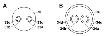
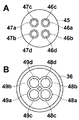
- A) A schematic view showing a structure of the cartridge according to the first embodiment in a bottom view.
- B) It is the schematic which shows the structure in the top view of the cartridge mounting part of 1st Embodiment.
- FIG. 10 is a schematic diagram showing a configuration of a cartridge storage chamber in the AA section in a second embodiment. It is a flowchart which shows the process of the replacement
- FIG. 1 is a schematic block diagram showing the configuration of the cooling system of this embodiment
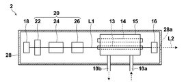
- FIG. 2 is a schematic cross-sectional view showing the configuration of the oscillator 2 of the solid-state laser oscillation device 1.
- FIG. 3 is a schematic perspective view showing the configuration of the reservoir unit 4 of the present embodiment.
- the solid-state laser oscillation device 1 of the present embodiment includes an oscillator 2 that oscillates a laser, and a circulation path 10 that uses the oscillator 2 as a heat absorption unit in the present invention.
- a circulation path 10 including a radiator (radiator) 3, a reservoir unit 4, a valve 5, a pump 6 and a filter 7 as elements on the path in this order, a control unit 8 for controlling the entire apparatus, and a mode switching input Part 9.
- the cooling system in the present embodiment includes a circulation path 10 including the reservoir unit 4, the valve 5, the pump 6, the filter 7, the oscillator 2, and the radiator 3 in this order as elements on the path, and a control unit that controls the whole. 8.
- the cooling system in the present embodiment is applied as a system for cooling the heat source in the solid-state laser oscillation device 1, that is, the laser rod.
- the cooling liquid as the circulating liquid in the circulation path 10 circulates in the direction of the arrow 11, for example.
- the structure of the oscillator 2 is not particularly limited, for example, as shown in FIG. 2, a laser rod 13, an excitation lamp 14, a laser chamber 15, an output mirror 16, a total reflection mirror 18, a Q switch 20, and a housing for housing them. 28.
- the oscillator 2 (particularly the laser chamber 15 in the oscillator 2) corresponds to a heat absorption part in the present invention.
- the laser rod 13 is a solid element including an active solid medium.
- a YAG rod composed of an yttrium aluminum garnet (YAG: Y 3 Al 5 O 12 ) crystal to which Nd 3- as an active medium is added. It is.
- the laser rod 13 is formed in a rod shape, for example.
- the laser rod 13 functions as a laser medium that receives light energy from the excitation lamp 14 and amplifies light of a specific wavelength.
- the light L1 stimulated and emitted from the laser rod 13 is amplified while resonating in a resonator composed of the output mirror 16 and the total reflection mirror 18, and then output as a laser L2 (FIG. 2).
- the laser rod 13 is preferably alexandrite.
- the excitation lamp 14 is a light source that supplies energy for the stimulated emission of the laser rod 13.
- the excitation lamp 14 is connected to a power source disposed outside the housing 28 (not shown).
- the laser chamber 15 includes a laser rod 13 and an excitation lamp 14 and is a member for condensing the light emitted from the excitation lamp 14 onto the laser rod 13.
- the laser chamber 15 has, for example, a cylindrical shape extending in the length direction of the laser rod 13 and the excitation lamp 14.
- the laser chamber 15 constitutes a part of the circulation path 10 of the cooling system, and is configured such that the coolant flowing in from the pipe 10a passes through the laser chamber 15 and then flows out from the pipe 10b. At this time, the cooling liquid is in direct contact with the laser rod 13 to perform heat exchange, and heat absorption to the laser rod 13 is performed.
- the Q switch 20 is disposed on the optical axis of the stimulated emission light L1 and between the laser rod 13 and the total reflection mirror 18.
- the Q switch 20 includes, for example, a ⁇ / 4 plate 22, a Pockels cell 24, and a polarizer 26.
- the housing 28 is formed in a rectangular parallelepiped shape, for example, and has an opening 28a for taking out the laser L2 on the side wall of the portion facing the output mirror 16.
- the radiator 3 is a so-called radiator and corresponds to a heat radiating portion in the present invention.
- the structure of the radiator 3 is not particularly limited, and a commonly used radiator can be used.
- the heat radiator 3 may be one in which a heat sink is brought into contact with a meandering pipe. Further, it is preferable to use a fan in combination in order to further enhance the heat dissipation effect.
- the reservoir unit 4 is a cooling liquid storage tank adopting a cartridge type. As shown in FIG. 3, the reservoir unit 4 of the present embodiment includes a cartridge 30 that stores a coolant, a cartridge mounting portion 31 that mounts the cartridge 30, and a cover 32 that covers the cartridge 30 after mounting the cartridge 30. Is done.
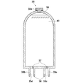
- the cartridge 30 has, for example, a tapered cylindrical shape, and has a storage chamber (coolant chamber 39) for storing the coolant 40 therein. Further, the cartridge 30 has connection portions 33a and 33b that enable connection to the cartridge mounting portion 31 on the bottom surface thereof. Each of the connecting portions 33a and 33b has communication ports 33c and 33d that communicate the outside of the cartridge with the coolant chamber 39, that is, connect the circulating fluid to flow therethrough. The communication ports 33c and 33d correspond to the first communication port in the present invention.
- connection portion 33a can supply the coolant 40 from the cartridge 30 to the cartridge mounting portion 31 via the communication port 33c
- connection portion 33b can be supplied from the cartridge mounting portion 31 to the cartridge 30 via the communication port 33d.
- the cooling liquid 40 can be fed to the tank.
- a case where one independent connection portion has one communication port will be described.
- a plurality of independent connection portions are provided in a state where the cooling liquid supply function and the recovery function are separated.
- the structure which has this communication port may be sufficient.
- the connecting portion 33a and the connecting portion 33b are formed with a cartridge valve 37 that prevents the internal coolant 40 from leaking before the cartridge 30 is attached to the cartridge attaching portion 31.
- the cartridge valve 37 is in an open state in a state where the connection portion 33a and the connection portion 33b are properly connected to the connection receiving portion 34a and the connection receiving portion 34b of the cartridge mounting portion 31, respectively. Further, it is preferable that the connection portion 33a and the connection portion 33b include an O-ring 38 so as not to form a gap when the cartridge 30 is properly attached to the cartridge attachment portion 31 (FIG. 5A).
- the cartridge 30 preferably has a hollow fiber membrane module 42 for filtering the dirt of the coolant inside.
- the hollow fiber membrane module 42 in FIG. 5B includes a hollow fiber membrane 42a that is bent in a bundled state and a holding case 42b that holds the end side of the hollow fiber membrane 42a.
- the holding case 42b has a hole and is connected to the communication port 33c. Therefore, the coolant 43a flowing from the communication port 33d first enters the hollow fiber membrane 42a, and then the coolant 43b that has permeated the hollow fiber membrane 42a can flow out to the communication port 33c through the hole.
- the hollow fiber membrane module 42 inside the cartridge 30 that is a part of the path through which the coolant circulates, the contamination of the coolant can be filtered, and when the cartridge 30 is replaced, the hollow fiber membrane module Can be exchanged at once.
- the filter 7 may not be provided.
- the cartridge 30 has, for example, a replenishment portion 33e for replenishing the coolant 40 on the top thereof, and the coolant 40 can be replenished by opening the cap of the replenishment portion 33e.
- a filter (not shown) that allows gas to permeate but does not allow liquid to permeate is disposed in a part of the cap so that air can enter and exit the inside and outside of the cartridge 30.
- at least a part of the cartridge 30 is preferably made of a transparent material (for example, a resin such as an acrylic resin) so that the degree of contamination of the coolant 40 in the cartridge 30 can be confirmed. In this case, it becomes possible to grasp the replacement time of the coolant 40 by visual observation.
- the cartridge mounting portion 31 is a guide portion having a shape (cylindrical shape in this embodiment) adapted to the shape of the cartridge 30 so as to guide the mounting of the cartridge 30, for example. 36. Further, the cartridge mounting portion 31 has a connection receiving portion 34a connectable to the connecting portion 33a and a connection receiving portion 34b connectable to the connecting portion 33b inside the guide portion 36.
- the connecting portions 34a and 34b have communication ports 34c and 34d, respectively.
- the communication ports 34c and 34d correspond to the second communication port in the present invention.
- the communication ports 33c and 34c communicate with each other when the connection portion 33a and the connection receiving portion 34a are connected, and the communication ports 33d and 34d communicate with each other when the connection portion 33b and the connection reception portion 34b are connected.
- the case where one independent connection receiving portion has one communication port will be described.
- the cooling liquid supply function and the recovery function are separated in correspondence with the connection portion, and the independent 1 One connection receiving portion may have a plurality of communication ports.
- the cartridge mounting part 31 has an outflow port 35 a and an inflow port 35 b for connecting the external circulation path and the cartridge 30.
- Each of the outflow port 35a and the inflow port 35b corresponds to a connection port in the present invention.
- the outflow port 35a communicates the communication port 34c with an external circulation path
- the inflow port 35b communicates the communication port 34d with an external circulation path. Therefore, as shown in FIG. 7, when the cartridge 30 is mounted in the cartridge mounting portion 31, the coolant chamber 39 in the cartridge 30 is connected to the outflow port 35a via the connection portion 33a and the connection receiving portion 34a. Then, it is connected to the inflow port 35b through the connection portion 33b and the connection receiving portion 34b.
- connection portion 33a, the connection receiving portion 34a, and the outflow port 35a constitute a supply path 11a that can supply the cooling liquid in the cooling liquid chamber 39 to the external circulation path
- connection portion 33b, the connection receiving portion 34b, and The inflow port 35b constitutes a recovery path 11b that allows the coolant from the external circulation path to be recovered in the coolant chamber 39.
- the cartridge mounting unit 31 preferably includes a sensor that detects whether or not the cartridge 30 is properly mounted on the cartridge mounting unit 31.
- the cartridge mounting portion 31 includes a sensor 41 in a part of the guide portion 36 that contacts the side surface of the cartridge 30 in a state where the cartridge 30 is properly mounted on the cartridge mounting portion 31.
- the device including the heat source is a solid-state laser oscillation device
- the detection signal of the sensor is output to the control unit 8.
- the sensor 41 is not particularly limited, and known sensors such as a micro switch, a magnetic sensor, and an optical sensor can be used.
- the cover 32 is for preventing dust and the like from accumulating on the cartridge 30 and the cartridge mounting portion 31, and protecting the cartridge 30 and the cartridge mounting portion 31 from external impacts. Therefore, it is not always essential in the present invention.
- valve 5 has at least three branches. One of the branches is connected to the gas introduction path 12 and the other two branches are connected to the circulation path 10.
- an electromagnetic valve can be used as the valve 5.
- the opening / closing of the valve may be controlled manually, but is controlled by the control unit 8 in this embodiment.
- the valve 5 is in a state where only the path between the gas introduction path 12 and the pump 6 is opened (first opening state) and in a state where only the path between the reservoir unit 4 and the pump 6 is opened (first (2 open state).
- the valve when the valve is in the first open state, the gas is introduced from the gas introduction path 12 into the circulation path 10, so that the coolant 40 in the circulation path 10 is pushed out to the gas, and the coolant 40 Is collected in the cartridge 30. At this time, the gas in the cartridge 30 escapes from the aforementioned filter portion of the cap.
- the pump 6 facilitates the feeding of the coolant 40 in the cartridge 30. Then, the coolant 40 in the cartridge 30 is supplied to the external circulation path, and the circulation path 10 is filled with the coolant 40.
- the position of the valve is preferably a position on the downstream side of the reservoir unit 4 and close to the reservoir unit 4 in order to collect more coolant 40.
- the gas introduction path 12 can introduce air as a gas.
- the gas introduction path 12 may be opened to the atmosphere. Further, the gas introduction path 12 may be connected to a cylinder containing dry air or nitrogen.
- the method of sending out the gas is not limited to the method using the valve 5 as described above.
- the coolant 6 in the circulation path 10 is caused to flow backward by rotating the pump 6 in the reverse direction, the air above the cartridge 30 is supplied to the circulation path 10. Therefore, in such a case, the valve 5 is unnecessary.
- the pump 6 feeds the coolant 40 in the circulation path 10, and is not particularly limited, and a general water feed pump can be used.
- the position of the pump is not limited to the position in this embodiment.
- the filter 7 removes dirt in the coolant 40 by filtering the coolant 40 in the circulation path 10. As a result, a clean coolant can be fed into the laser chamber 15 and contamination of the laser rod 13 can be reduced.
- the filter is not essential in the present invention.
- the control unit 8 controls the solid-state laser oscillation device 1 and the entire cooling system, and is realized by an information processing device such as a computer.
- the control unit 8 controls the solid-state laser oscillation device 1 to prohibit the use of the flash lamp 14 in the oscillator 2 based on a detection signal from the sensor 41 of the cartridge mounting unit 31.
- the control unit 8 when receiving a signal indicating that the cooling system is not normal, the control unit 8 performs control so that the flash lamp is not turned on.
- the control unit 8 also controls the opening and closing of the valve 5.
- the control unit 8 can also control the rotation direction of the pump 6 and monitor the degree of contamination of the filter 7.
- the mode switching input unit 9 makes it possible for an operator who performs a replacement operation of the coolant 40 to select a start-up mode of the cooling system such as a coolant recovery mode, a coolant circulation mode, and a cleaning mode, for example. .
- Information on the selected mode is transmitted from the mode switching input unit 9 to the control unit 8, and the control unit 8 performs necessary control on the valve 5, the pump 6, and the like based on the information.
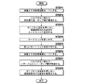
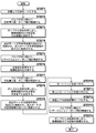
- FIG. 8 is a flowchart showing the steps of the coolant replacement operation in the present embodiment.
- the operator sets the mode of the cooling system to the coolant recovery mode by the mode switching input unit 9 (STEP 1).
- the control unit 8 switches the state of the valve 5 from the second open state to the first open state (STEP 2).
- gas is introduced from the gas introduction path 12 into the circulation path 10, and the coolant 40 is pushed out into the coolant chamber 39 of the cartridge 30.
- 40 is collected in the cartridge 30 (STEP 3).
- the external circulation path is filled with gas.
- the current cartridge 30 is removed (STEP 4), and the cartridge 30 containing the new coolant 40 is mounted on the cartridge mounting portion 31 (STEP 5).
- the mode of the cooling system is manually or automatically switched to the coolant circulation mode (STEP 6).
- the controller 8 switches the valve state of the valve 5 from the first open state to the second open state (STEP 7).
- the cooling liquid 40 is supplied from the cartridge 30 into the external circulation path, and the cooling liquid 40 starts to circulate in the circulation path 10 as the circulation liquid (STEP 8 )
- the circulation path 10 is filled with the coolant 40, the replacement operation of the coolant 40 is completed.
- the tank for storing the coolant is made into the cartridge type, so that the cartridge is attached to and detached from the cartridge mounting portion.
- the cooling liquid can be recovered and replaced only by this. As a result, in the cooling system that circulates the cooling liquid, the replacement work of the cooling liquid can be facilitated.
- the cartridge can adopt a mode having a plurality of divided storage chambers partitioned from each other inside.
- a connection portion for connecting to the cartridge mounting portion is provided in the cartridge for each divided storage chamber, and a plurality of connection receiving portions on the cartridge mounting portion side are provided in accordance with the number of connection portions.
- each of the divided storage chambers may store different kinds of circulating fluids or may store the same kind of circulating fluids.
- the coolant can be changed by changing the storage chamber connected to the outflow port and the inflow port without preparing a new cartridge. Can be exchanged.
- the outflow port and the inflow port are connected to the communication port in the connection receiving portion provided in a plurality according to the number of the divided storage chambers with the cartridge mounted in the cartridge mounting portion. It can be connected to any one of them. However, in this case, it is not necessary that the outflow port and the inflow port can be connected to all the divided storage chambers in a predetermined mounting state of the cartridge and the cartridge mounting portion. In other words, it cannot be connected to the outflow port and inflow port in a certain mounting state, but it can be connected to the outflow port and inflow port when the relative positional relationship between the cartridge and the cartridge mounting portion is changed from this mounting state.
- There may be a divided storage chamber. The change of the relative positional relationship includes, for example, rotating the cartridge or inverting the cartridge upside down.
- Each of the outflow port and the inflow port is connected to a divided storage chamber having a circulating fluid to be supplied into the circulation path.
- FIG. 9A is a schematic view showing the structure of the cartridge 45 according to this embodiment in a bottom view
- FIG. 9B is a schematic view showing the structure of the cartridge mounting portion according to this embodiment in a top view
- FIG. 10 is a schematic view showing the configuration of the storage chamber of the cartridge 45 in the present embodiment, taken along the line AA.
- the solid-state laser oscillation device 1 of the present embodiment includes an oscillator 2 that oscillates a laser, and a circulation path 10 that uses the oscillator 2 as a heat absorption unit.
- a circulation path 10 including the unit 4, the valve 5, the pump 6, and the filter 7 as elements on the path in this order, a control unit 8 that controls the entire apparatus, and a mode switching input unit 9 are configured.
- the cooling system in the present embodiment includes the reservoir unit 4, the valve 5, the pump 6, the filter 7, the oscillator 2, and the radiator 3 in this order as elements on the path, as in the case of the first embodiment. It is comprised from the circulation path 10 and the control part 8 which controls the whole.
- the cartridge 45 of this embodiment has two divided storage chambers, a cooling liquid chamber 50 for storing the cooling liquid and a cleaning liquid chamber 51 for storing the cleaning liquid.
- the cooling liquid chamber 50 and the cleaning liquid chamber 51 are partitioned by a partition 52.
- the cartridge 45 has connection portions 46a, 46b, 47a and 47b that enable connection with the cartridge mounting portion.
- the connecting portions 46a and 46b have communication ports 46c and 46d that respectively communicate the outside of the cartridge with the coolant chamber 50, and the connecting portions 47a and 47b have communication ports 47c and 47d that respectively communicate the outside of the cartridge with the cleaning solution chamber 51.
- the connecting portion 46a can supply the coolant from the coolant chamber 50 to the cartridge mounting portion via the communication port 46c, and the connecting portion 46b is cooled from the cartridge mounting portion via the communication port 46d.
- the cooling liquid can be supplied to the liquid chamber 50.
- the connecting portion 47a allows the cleaning liquid to be sent from the cleaning liquid chamber 51 to the cartridge mounting portion via the communication port 47c, and the connecting portion 47b is connected to the cleaning liquid chamber 51 from the cartridge mounting portion via the communication port 47d. It has the structure which enables liquid feeding of a washing
- the cartridge mounting portion includes a connection receiving portion 48a connectable to the connecting portion 46a, a connection receiving portion 48b connectable to the connecting portion 46b, a connection receiving portion 49a connectable to the connecting portion 47a, and a connection inside the guide portion 36. It has the connection receiving part 49b which can be connected with the part 47b.
- the outflow port and the inflow port have a configuration that can be switched and connected to either the cooling liquid chamber 50 or the cleaning liquid chamber 51. That is, as a connection form of the outflow port and the inflow port in the present embodiment, the coolant chamber 50 is connected to the outflow port via the connection portion 46a and the connection receiving portion 48a, and via the connection portion 46b and the connection receiving portion 48b.
- the cooling liquid chamber 50 is connected to the inflow port, or the cleaning liquid chamber 51 is connected to the outflow port via the connecting portion 47a and the connection receiving portion 49a, and the cleaning liquid chamber 51 is connected via the connecting portion 47b and the connecting receiving portion 49b.
- Such switching of the connection of the outflow port is performed by, for example, flowing out the branch paths connected to the communication port 48c of the connection receiving part 48a on the cooling liquid chamber 50 side and the communication port 49c of the connection receiving part 49a on the cleaning liquid chamber 51 side.
- This can be implemented by forming a port and switching one of the branch paths with a shutter. The same applies to the inflow port.
- FIG. 11 is a flowchart showing a process of replacing the coolant in the present embodiment.
- the circulation path is cleaned using the cleaning liquid remaining in the cartridge 45 before the replacement of the cooling liquid. This is to prevent the coolant from becoming dirty immediately after replacement due to contamination in the circulation path. Therefore, the operator sets the mode of the cooling system to the cleaning mode by the mode switching input unit 9 (STEP 1). At this time, the control unit 8 switches the state of the valve 5 from the second open state to the first open state (STEP 2). By opening the path between the gas introduction path 12 and the pump 6, the gas is introduced from the gas introduction path 12 into the circulation path 10, the coolant is pushed out into the coolant chamber 50 of the cartridge 45, and the coolant is It is collected in the cartridge 45 (STEP 3).
- connection of the connection port is switched from the cooling liquid chamber 50 side to the cleaning liquid chamber 51 side (STEP 4).
- the controller 8 switches the valve state of the valve 5 from the first open state to the second open state (STEP 5).
- the cleaning liquid is supplied from the cartridge 45 into the external circulation path, and the cleaning liquid circulates in the circulation path 10 as the circulating liquid and cleans the circulation path 10.
- the control unit 8 switches the valve state of the valve 5 from the second open state to the first open state (STEP 7).
- connection of the connection port is switched from the cleaning liquid chamber 51 side to the cooling liquid chamber 50 side (STEP 9).
- the current cartridge 45 is removed (STEP 10), and a cartridge 45 containing new coolant and cleaning liquid is mounted on the cartridge mounting portion (STEP 11).
- the mode of the cooling system is manually or automatically switched to the coolant circulation mode (STEP 12).
- the controller 8 switches the valve state of the valve 5 from the first open state to the second open state (STEP 13).
- the cooling liquid is supplied from the cartridge 45 into the external circulation path, and the cooling liquid starts to circulate in the circulation path 10 as the circulation liquid (STEP 14).
- the coolant replacement operation is completed by filling the circulation path 10 with the coolant.
- the cleaning liquid remaining in the cartridge 45 can be used to start work from the cleaning of the circulation path.
- the timing of cleaning does not necessarily need to be immediately before the coolant replacement operation.
- the circulation path may be periodically cleaned at a cycle shorter than the replacement of the cooling liquid independently of the replacement of the cooling liquid.
- the cartridge is not removed, and the process proceeds to STEP 12 where the cooling liquid circulation mode is set as it is.
- the cooling system, the reservoir unit, the cartridge, and the solid-state laser oscillation device including them according to the present embodiment can provide the same effects as those of the first embodiment.
- the cartridge since the cartridge has the cleaning liquid in addition to the cooling liquid, it is possible to easily remove the dirt in the circulation path.
- the first monitoring unit for monitoring the excitation intensity of the excitation lamp 14 and the second monitoring unit for monitoring the output intensity of the laser light L2 output from the oscillator 2 are provided. Different from the embodiment. Therefore, a detailed description of the same configuration as that of the first embodiment is omitted unless particularly required. In addition, the same code
- FIG. 12 is a schematic diagram showing the configuration of the periphery of the laser chamber 15 and the second monitoring unit of the present embodiment.
- the solid-state laser oscillation device 1 of the present embodiment includes a voltage monitoring circuit 17 as a first monitoring unit, and a beam splitter 54 and an optical sensor 55 as a second monitoring unit.
- the voltage monitoring circuit 17 measures the voltage applied to the excitation lamp 14. Then, the voltage monitoring circuit 17 generates a signal having an intensity corresponding to the measured voltage intensity, and outputs the signal to the control unit 8.
- the beam splitter 54 divides and extracts a part (for example, 1%) of the laser light L2 as monitoring light (monitoring light).
- the light sensor 55 detects monitoring light. Then, the optical sensor 55 generates a signal having an intensity corresponding to the detected intensity of the monitoring light, and outputs the signal to the control unit 8.
- the position of the optical sensor 55 is not limited to the position where a part of the laser light L2 actually output from the oscillator 2 is detected as in the present embodiment.
- the arrangement of the optical sensor 55 can be a position where the light transmitted through the mirror 18 is detected in the oscillator 2 if the mirror 18 is replaced with one that transmits a part of the light.
- the control unit 8 simulates the intensity of the signal output from the voltage monitoring circuit 17 as the excitation intensity of the excitation lamp, and on the other hand, simulates the intensity of the signal output from the optical sensor 55 as the output intensity of the laser beam L2. Based on the excitation intensity and the output intensity, it is determined whether or not the circulating fluid circulating in the circulation path is contaminated.
- the control unit 8 also functions as a determination unit in the present invention. For example, when the circulating fluid is contaminated, the light emitted from the excitation lamp 14 reaches the laser rod 13 while being greatly attenuated. Therefore, when the circulating fluid is contaminated, the ratio of the output intensity to the excitation intensity is reduced as compared with the case where the circulating fluid is not contaminated.
- control unit 8 can determine whether or not the circulating fluid has been contaminated based on the magnitude of the output intensity with respect to the excitation intensity.
- control unit 8 controls the solid-state laser oscillation device 1 so as to issue a warning, for example, by displaying that fact on a display unit (not shown).
- the cooling system, the reservoir unit, the cartridge, and the solid-state laser oscillation device including them according to the present embodiment can provide the same effects as those of the first embodiment.
- this embodiment has a monitoring system that determines whether or not the circulating fluid is contaminated, it is possible to easily know the replacement timing of the circulating fluid.
- the present invention is not limited to this.
- the present invention can be used as a cooling system for another laser device such as a semiconductor laser or an information processing unit such as a server by combining with a heat sink.
- the solid-state laser oscillation device of the present invention can be used for a photoacoustic image generation device as shown in FIG. 13, for example. 13 includes an imaging control unit 71, a laser light source 72 including the solid-state laser oscillation device of the present invention, an image generation unit 73, a display unit 74, an operation unit 75 (user interface), and a probe. A child 76 is provided.
- the imaging control unit 71 controls the laser light source 72, the image generation unit 73, the display unit 74, and the operation unit 75.
- the imaging control unit 71 outputs a trigger signal for synchronizing them, for example.
- the laser light source 72 outputs laser light L to be irradiated to the test site M as measurement light.
- the laser light source 72 includes, for example, one or more light sources that generate laser light having a wavelength included in a blood absorption peak.
- the wavelength of the laser light L is appropriately determined according to the light absorption characteristics of the substance in the subject M to be imaged.
- the imaging target is hemoglobin in a living body (that is, when imaging a blood vessel inside the living body)
- the light transmittance of the living body is good, and various hemoglobins have a light absorption peak of about 600 to 1000 nm. It is preferable.
- the image generation unit 73 generates a photoacoustic image from the acoustic signal detected by the probe 76. For example, the position of the time axis in the acoustic signal data for one line is converted into the position of the displacement axis representing the depth in the tomographic image to construct image data for one frame. Furthermore, if necessary, based on the image data for one frame generated for each scanning position of the probe 76, the image data for one frame is superimposed and arranged in virtual space coordinates or acquired. Volume data for 3D photoacoustic images is constructed while interpolating between the data.
- the display unit 74 displays a photoacoustic image based on the image data generated by the image generation unit 73.
- the operation unit 75 is for the user to input information necessary for imaging.
- the user uses the operation unit 75 to specify a viewpoint direction when a photoacoustic image is displayed, or to input information about patient information or imaging conditions.
- the probe 76 includes a light irradiation unit 77 and a transducer array 78, and irradiates a laser beam L to the test site M to detect a photoacoustic wave U from the test site M.
Landscapes
- Physics & Mathematics (AREA)
- Engineering & Computer Science (AREA)
- Electromagnetism (AREA)
- Optics & Photonics (AREA)
- Plasma & Fusion (AREA)
- Thermal Sciences (AREA)
- Microelectronics & Electronic Packaging (AREA)
- Mechanical Engineering (AREA)
- General Engineering & Computer Science (AREA)
- Condensed Matter Physics & Semiconductors (AREA)
- General Physics & Mathematics (AREA)
- Lasers (AREA)
- Chemical & Material Sciences (AREA)
- Combustion & Propulsion (AREA)
Abstract
【課題】循環液を循環させる冷却システムにおいて、循環液の交換作業を容易にすることを可能とする。 【解決手段】冷却システムにおいて、循環経路(10)上の要素として含まれるリザーバユニット(4)を、着脱可能に構成されたカートリッジ(30)およびカートリッジ装着部(31)を有するものとする。カートリッジ(30)は、循環液(40)を貯留する貯留室(39)と貯留室(39)に連通する接続部(33aおよび33b)とを有する。カートリッジ装着部(31)は、接続部が接続される接続受け部(34aおよび34b)と接続ポート(35aおよび35b)とを有する。接続部、接続受け部および接続ポートは、カートリッジ(30)およびカートリッジ装着部(31)が装着された状態で、循環液(40)を外部の循環経路へ供給可能とする供給経路(11a)と、循環液(40)を貯留室(39)に回収可能とする回収経路(11b)とを構成する。
Description
本発明は、装置内の発熱源を冷却するための冷却液が循環する循環経路を備えた冷却システム、それに用いられるリザーバユニットおよびカートリッジに関するものである。また、本発明は、上記冷却システムを備えた固体レーザ発振装置に関するものである。
固体レーザの場合、励起源としてのフラッシュランプから可視光あるいは近可視光が放射され、この光エネルギーがレーザロッド内で蓄えられてレーザビームへと変換される。しかしながら、この場合のエネルギー変換効率が低いため、フラッシュランプからの光エネルギーの多くの部分が熱に変換される。このとき、レーザロッド内でのエネルギー効率は、温度の上昇に伴い低下してしまう。
そこで、通常固体レーザでは、レーザロッドを冷却するための冷却システムを備えている(例えば特許文献1)。このような冷却システムは、例えば図14に示されるように、発熱源であるレーザロッドを含む共振器80(或いはレーザチャンバ)、放熱器81、リザーバタンク82、ポンプ83およびフィルタ84を含む循環経路85から構成されるものである。循環経路85内において、リザーバタンク82からポンプ83によって送液された冷却液は、フィルタ84を通過して異物が除去された後、共振器80内のレーザロッドに直接接触することによりレーザロッドで発生した熱を吸収する。吸熱した冷却液は放熱器81で放熱した後リザーバタンク82に戻される。冷却液は、上記の工程を繰り返すように循環経路を循環することとなる。
ところで、冷却液は、繰り返し循環経路を循環する中で水垢の発生等により汚れが生じるため、定期的に新しい冷却液に交換される。従来この冷却液の交換作業は、スポイト等でリザーバタンクから冷却液を抜き取った後、新しい冷却液をリザーバタンクに補給することにより実施される。
しかしながら、上記のような交換作業では、冷却システムについての専門知識を有する者が行う必要があったり、交換作業に手間がかかったり、冷却液がこぼれる可能性があったりという問題がある。例えば、こぼれた冷却液がレーザの高電圧部分に掛かると漏電の原因となるし、医療現場等では冷却液がこぼれること自体、衛生面上好ましくない。
本発明は上記問題に鑑みてなされたものであり、冷却液等の循環液を循環させる冷却システムにおいて、循環液の交換作業を容易にすることを可能とする冷却システムおよびリザーバユニット並びにそれらを備えた固体レーザ発振装置を提供することを目的とするものである。
上記課題を解決するために、本発明に係る冷却システムは、
循環液が循環する循環経路を備えた、発熱源を冷却するための冷却システムにおいて、
循環経路が、循環液を貯留するリザーバユニットと、循環経路内で循環液を送液するポンプと、発熱源から発生した熱を循環液としての冷却液で吸収する吸熱部と、冷却液の熱を放出する放熱部とを経路上の要素として含むものであり、
リザーバユニットが、相互に着脱可能に構成されたカートリッジおよびカートリッジ装着部を有するものであり、
カートリッジが、循環液を貯留する貯留室と、貯留室に連通する第1連通口を有する接続部とを有するものであり、
カートリッジ装着部が、接続部が接続される接続受け部であって接続部が接続受け部に接続された際に第1連通口と連通する第2連通口を有する接続受け部と、第2連通口を外部の循環経路へ連通する接続ポートとを有するものであり、
接続部、接続受け部および接続ポートが、カートリッジおよびカートリッジ装着部が相互に装着された状態で、貯留室内の循環液を外部の循環経路へ供給可能とする供給経路と、外部の循環経路からの循環液を貯留室に回収可能とする回収経路とを構成することを特徴とするものである。
循環液が循環する循環経路を備えた、発熱源を冷却するための冷却システムにおいて、
循環経路が、循環液を貯留するリザーバユニットと、循環経路内で循環液を送液するポンプと、発熱源から発生した熱を循環液としての冷却液で吸収する吸熱部と、冷却液の熱を放出する放熱部とを経路上の要素として含むものであり、
リザーバユニットが、相互に着脱可能に構成されたカートリッジおよびカートリッジ装着部を有するものであり、
カートリッジが、循環液を貯留する貯留室と、貯留室に連通する第1連通口を有する接続部とを有するものであり、
カートリッジ装着部が、接続部が接続される接続受け部であって接続部が接続受け部に接続された際に第1連通口と連通する第2連通口を有する接続受け部と、第2連通口を外部の循環経路へ連通する接続ポートとを有するものであり、
接続部、接続受け部および接続ポートが、カートリッジおよびカートリッジ装着部が相互に装着された状態で、貯留室内の循環液を外部の循環経路へ供給可能とする供給経路と、外部の循環経路からの循環液を貯留室に回収可能とする回収経路とを構成することを特徴とするものである。
本明細書において「外部の循環経路」とは、リザーバユニットから見た外部の循環経路、すなわちリザーバユニットを含まない循環経路部分を意味する。
そして、本発明に係る冷却システムにおいて、循環経路は、リザーバユニットとポンプとの間に、分岐を有するバルブであって当該分岐のうち1つの分岐が気体導入路に接続され他の2つの分岐が循環経路に接続されたバルブを含むものであり、
バルブは、循環液を貯留室に回収する場合には気体導入路とポンプとの間の経路が開通した状態となるように開閉可能な弁であって、循環液を貯留室から供給する場合にはリザーバユニットとポンプとの間の経路が開通した状態となるように開閉可能な弁を有するものであることが好ましい。この場合において、気体導入路は気体として空気を導入するものとすることができる。
バルブは、循環液を貯留室に回収する場合には気体導入路とポンプとの間の経路が開通した状態となるように開閉可能な弁であって、循環液を貯留室から供給する場合にはリザーバユニットとポンプとの間の経路が開通した状態となるように開閉可能な弁を有するものであることが好ましい。この場合において、気体導入路は気体として空気を導入するものとすることができる。
また、本発明に係る冷却システムにおいて、貯留室は、相互に仕切られた複数の分割貯留室から構成されるものであり、
接続部は、複数の分割貯留室のそれぞれに対応してカートリッジに複数設けられたものであり、
接続受け部は、複数の接続部のそれぞれに対応してカートリッジ装着部に複数設けられたものであり、
接続ポートは、複数の接続受け部の複数の第2連通口それぞれに対して切り替えて接続可能なものであることが好ましい。
接続部は、複数の分割貯留室のそれぞれに対応してカートリッジに複数設けられたものであり、
接続受け部は、複数の接続部のそれぞれに対応してカートリッジ装着部に複数設けられたものであり、
接続ポートは、複数の接続受け部の複数の第2連通口それぞれに対して切り替えて接続可能なものであることが好ましい。
この場合において、複数の分割貯留室のうち1つは循環液の1つとしての冷却液を貯留するものであり、他の1つは循環液の他の1つとして洗浄液を貯留するものであることが好ましい。
また、本発明に係る冷却システムにおいて、カートリッジの少なくとも一部は、カートリッジ内の循環液の汚れの程度を確認できるように透明な材料で構成されていることが好ましい。
また、本発明に係る冷却システムにおいて、リザーバユニットは、カートリッジがカートリッジ装着部に適正に装着されたか否かを検出するセンサを有し、
カートリッジおよびカートリッジ装着部が適正に装着されたことがセンサによって検出されないときに、発熱源が発熱する要因を排除する制御部を備えることが好ましい。
カートリッジおよびカートリッジ装着部が適正に装着されたことがセンサによって検出されないときに、発熱源が発熱する要因を排除する制御部を備えることが好ましい。
本発明に係るリザーバユニットは、
循環液が循環する循環経路上の要素として用いられるリザーバユニットであって、
相互に着脱可能に構成されたカートリッジおよびカートリッジ装着部を備え、
カートリッジは、循環液を貯留する貯留室と、貯留室に連通する第1連通口を有する接続部とを有するものであり、
カートリッジ装着部は、接続部が接続される接続受け部であって接続部が接続受け部に接続された際に第1連通口と連通する第2連通口を有する接続受け部と、第2連通口を外部の循環経路へ連通する接続ポートとを有するものであり、
接続部、接続受け部および接続ポートは、カートリッジおよびカートリッジ装着部が相互に装着された状態で、貯留室内の循環液を外部の循環経路へ供給可能とする供給経路と、外部の循環経路からの循環液を貯留室に回収可能とする回収経路とを構成することを特徴とするものである。
循環液が循環する循環経路上の要素として用いられるリザーバユニットであって、
相互に着脱可能に構成されたカートリッジおよびカートリッジ装着部を備え、
カートリッジは、循環液を貯留する貯留室と、貯留室に連通する第1連通口を有する接続部とを有するものであり、
カートリッジ装着部は、接続部が接続される接続受け部であって接続部が接続受け部に接続された際に第1連通口と連通する第2連通口を有する接続受け部と、第2連通口を外部の循環経路へ連通する接続ポートとを有するものであり、
接続部、接続受け部および接続ポートは、カートリッジおよびカートリッジ装着部が相互に装着された状態で、貯留室内の循環液を外部の循環経路へ供給可能とする供給経路と、外部の循環経路からの循環液を貯留室に回収可能とする回収経路とを構成することを特徴とするものである。
そして、本発明に係るリザーバユニットにおいて、貯留室は、相互に仕切られた複数の分割貯留室から構成されるものであり、
接続部は、複数の分割貯留室のそれぞれに対応してカートリッジに複数設けられたものであり、
接続受け部は、複数の接続部のそれぞれに対応してカートリッジ装着部に複数設けられたものであり、
接続ポートは、複数の接続受け部の複数の第2連通口それぞれに対して切り替えて接続可能なものであることが好ましい。
接続部は、複数の分割貯留室のそれぞれに対応してカートリッジに複数設けられたものであり、
接続受け部は、複数の接続部のそれぞれに対応してカートリッジ装着部に複数設けられたものであり、
接続ポートは、複数の接続受け部の複数の第2連通口それぞれに対して切り替えて接続可能なものであることが好ましい。
この場合において、リザーバユニットは、発熱源を冷却するための冷却システムに用いられるものであり、複数の分割貯留室のうち1つは循環液の1つとしての冷却液を貯留するものであり、他の1つは循環液の他の1つとして洗浄液を貯留するものであることが好ましい。
また、本発明に係るリザーバユニットにおいて、カートリッジの少なくとも一部は、カートリッジ内の循環液の汚れの程度を確認できるように透明な材料で構成されていることが好ましい。
また、本発明に係るリザーバユニットにおいて、リザーバユニットは、カートリッジがカートリッジ装着部に適正に装着されたか否かを検出するセンサを有するものであることが好ましい。
本発明に係るカートリッジは、
循環液が循環する循環経路上の要素として用いられるリザーバユニットを構成するカートリッジであって、
カートリッジに設けられた第1連通口と連通する第2連通口を有する接続受け部と、第2連通口を外部の循環経路へ連通する接続ポートとを有するカートリッジ装着部に着脱可能に構成され、
循環液を貯留する貯留室と、
貯留室に連通する第1連通口を有する接続部とを備え、
接続部が、接続受け部および接続ポートと協同して、カートリッジおよびカートリッジ装着部が相互に装着された状態で、貯留室内の循環液を外部の循環経路へ供給可能とする供給経路と、外部の循環経路からの循環液を貯留室に回収可能とする回収経路とを構成することを特徴とするものである。
循環液が循環する循環経路上の要素として用いられるリザーバユニットを構成するカートリッジであって、
カートリッジに設けられた第1連通口と連通する第2連通口を有する接続受け部と、第2連通口を外部の循環経路へ連通する接続ポートとを有するカートリッジ装着部に着脱可能に構成され、
循環液を貯留する貯留室と、
貯留室に連通する第1連通口を有する接続部とを備え、
接続部が、接続受け部および接続ポートと協同して、カートリッジおよびカートリッジ装着部が相互に装着された状態で、貯留室内の循環液を外部の循環経路へ供給可能とする供給経路と、外部の循環経路からの循環液を貯留室に回収可能とする回収経路とを構成することを特徴とするものである。
そして、本発明に係るカートリッジにおいて、貯留室は、相互に仕切られた複数の分割貯留室から構成されるものであり、
接続部は、複数の分割貯留室のそれぞれに対応してカートリッジに複数設けられたものであることが好ましい。
接続部は、複数の分割貯留室のそれぞれに対応してカートリッジに複数設けられたものであることが好ましい。
この場合において、カートリッジは、発熱源を冷却するための冷却システムに用いられるものであり、複数の分割貯留室のうち1つは循環液の1つとしての冷却液を貯留するものであり、他の1つは循環液の他の1つとして洗浄液を貯留するものであることが好ましい。
また、本発明に係るカートリッジにおいて、カートリッジの少なくとも一部は、カートリッジ内の循環液の汚れの程度を確認できるように透明な材料で構成されていることが好ましい。
また、本発明に係るカートリッジにおいて、冷却液の汚れをろ過するためのフィルタを貯留室内部に有することが好ましい。この場合において、フィルタは中空糸膜フィルタであることが好ましい。
本発明に係る固体レーザ発振装置は、
上記に記載の冷却システムと、
レーザロッドと、
レーザロッドを励起する励起ランプと、
レーザロッドおよび励起ランプを内包するレーザチャンバとを備え、
レーザチャンバが、冷却システムの吸熱部として循環経路の一部を構成するものであることを特徴とするものである。
上記に記載の冷却システムと、
レーザロッドと、
レーザロッドを励起する励起ランプと、
レーザロッドおよび励起ランプを内包するレーザチャンバとを備え、
レーザチャンバが、冷却システムの吸熱部として循環経路の一部を構成するものであることを特徴とするものである。
本発明に係る冷却システム、リザーバユニットおよびカートリッジ並びにそれらを備えた固体レーザ発振装置によれば、冷却液等の循環液を貯留するタンクをカートリッジ式にしたため、カートリッジをカートリッジ装着部に着脱するだけで、循環経路に供給された循環液の回収および交換が行える。この結果、循環液を循環させる冷却システムにおいて、循環液の交換作業を容易にすることが可能となる。
以下、本発明の実施形態について図面を用いて説明するが、本発明はこれに限られるものではない。なお、視認しやすくするため、図面中の各構成要素の縮尺等は実際のものとは適宜異ならせてある。
「第1の実施形態」
冷却システムおよびリザーバユニット並びにそれらを備えた固体レーザ発振装置の第1の実施形態について説明する。図1は本実施形態の冷却システムの構成を示す概略ブロック図であり、図2は固体レーザ発振装置1の発振器2の構成を示す概略断面図である。また、図3は、本実施形態のリザーバユニット4の構成を示す概略斜視図である。
冷却システムおよびリザーバユニット並びにそれらを備えた固体レーザ発振装置の第1の実施形態について説明する。図1は本実施形態の冷却システムの構成を示す概略ブロック図であり、図2は固体レーザ発振装置1の発振器2の構成を示す概略断面図である。また、図3は、本実施形態のリザーバユニット4の構成を示す概略斜視図である。
本実施形態の固体レーザ発振装置1は、図1に示されるように、レーザを発振させる発振器2と、この発振器2を本発明における吸熱部とする循環経路10であって、本発明における放熱部としての放熱器(ラジエータ)3、リザーバユニット4、バルブ5、ポンプ6およびフィルタ7をその経路上の要素としてこの順に含む循環経路10と、装置の全体を制御する制御部8と、モード切替入力部9とから構成される。
そして、本実施形態における冷却システムは、リザーバユニット4、バルブ5、ポンプ6、フィルタ7、発振器2および放熱器3をその経路上の要素としてこの順に含む循環経路10と、全体を制御する制御部8とから構成される。つまり、本実施形態における冷却システムは、固体レーザ発振装置1内の発熱源、つまりレーザロッドを冷却するためのシステムとして適用されたものである。なお、循環経路10内の循環液としての冷却液は、例えば矢印11の方向に循環する。
(発振器)
発振器2の構造は、特に限定されないが例えば図2に示されるように、レーザロッド13、励起ランプ14、レーザチャンバ15、出力ミラー16、全反射ミラー18、Qスイッチ20およびこれらを収容する筐体28から構成される。発振器2(特に発振器2内のレーザチャンバ15)は本発明における吸熱部に相当する。
発振器2の構造は、特に限定されないが例えば図2に示されるように、レーザロッド13、励起ランプ14、レーザチャンバ15、出力ミラー16、全反射ミラー18、Qスイッチ20およびこれらを収容する筐体28から構成される。発振器2(特に発振器2内のレーザチャンバ15)は本発明における吸熱部に相当する。
レーザロッド13は、活性固体媒体を含む固体素子であり、例えば、活性媒体であるNd3-が添加されたイットリウム・アルミニウム・ガーネット(YAG:Y3Al5O12)結晶から構成されたYAGロッドである。レーザロッド13は例えば棒状に形成されている。レーザロッド13は、励起ランプ14からの光エネルギーを受け取って、特定の波長の光を増幅するレーザ媒質として機能する。このレーザロッド13から誘導放出された光L1は、出力ミラー16および全反射ミラー18から構成される共振器内で共振しながら増幅され、その後レーザL2として出力される(図2)。なお、レーザロッド13はアレキサンドライトであることが好ましい。
励起ランプ14は、レーザロッド13が誘導放出するためのエネルギーを供給する光源である。励起ランプ14は、例えば、Xeガスが封入された棒状のフラッシュランプを採用することができる。励起ランプ14は、図示しない筐体28の外部に配置された電源に接続されている。
レーザチャンバ15は、レーザロッド13および励起ランプ14を包含し、励起ランプ14から放射された光をレーザロッド13へ集光するための部材である。レーザチャンバ15は、例えばレーザロッド13および励起ランプ14の長さ方向に伸びた筒形状を有する。レーザチャンバ15は、冷却システムの循環経路10の一部を構成し、配管10aから流入した冷却液がレーザチャンバ15の内部を通り、その後配管10bから流出するように構成されている。この時、冷却液がレーザロッド13と直接接触して熱交換が行われることになり、レーザロッド13に対する吸熱が行われる。
Qスイッチ20は、誘導放出された光L1の光軸上であって、レーザロッド13と全反射ミラー18との間に配置されている。Qスイッチ20は、例えばλ/4板22、ポッケルスセル24およびポラライザ26から構成される。
筐体28は、例えば直方体形状に形成されており、出力ミラー16に対向する部分の側壁にレーザL2を取り出すための開口28aを有する。
(放熱器)
放熱器3は、いわゆるラジエータであり、本発明における放熱部に相当する。放熱器3の構造は特に限定されず、一般的に使用されるラジエータを使用することが可能である。例えば放熱器3として、蛇行させた配管にヒートシンクを接触させたもの等を採用することができる。また、さらに放熱効果を高めるためにファンを併用することが好ましい。
放熱器3は、いわゆるラジエータであり、本発明における放熱部に相当する。放熱器3の構造は特に限定されず、一般的に使用されるラジエータを使用することが可能である。例えば放熱器3として、蛇行させた配管にヒートシンクを接触させたもの等を採用することができる。また、さらに放熱効果を高めるためにファンを併用することが好ましい。
(リザーバユニット)
リザーバユニット4は、カートリッジ式を採用した冷却液の貯留タンクである。本実施形態のリザーバユニット4は、図3に示されるように、冷却液を貯留するカートリッジ30、カートリッジ30を装着するカートリッジ装着部31、およびカートリッジ30を装着した後カートリッジ30を覆うカバー32から構成される。
リザーバユニット4は、カートリッジ式を採用した冷却液の貯留タンクである。本実施形態のリザーバユニット4は、図3に示されるように、冷却液を貯留するカートリッジ30、カートリッジ30を装着するカートリッジ装着部31、およびカートリッジ30を装着した後カートリッジ30を覆うカバー32から構成される。
カートリッジ30は、図3、図4のAおよび図5Aに示されるように、例えば先細りの円筒形状であり、内部に冷却液40を貯留する貯留室(冷却液室39)を有する。またカートリッジ30は、その底面にカートリッジ装着部31との接続を可能にする接続部33aおよび33bを有する。接続部33aおよび33bは、それぞれカートリッジ外部を冷却液室39に連通する、つまり循環液が流通するように連結する連通口33cおよび33dを有する。連通口33cおよび33dが本発明における第1連通口に相当する。これにより例えば、接続部33aは連通口33cを介してカートリッジ30からカートリッジ装着部31への冷却液40の送液を可能とし、接続部33bは連通口33dを介してカートリッジ装着部31からカートリッジ30への冷却液40の送液を可能とする。なお、本実施形態では独立した1つの接続部が1つの連通口を有する場合について説明するが、本発明では冷却液の供給機能と回収機能が分離された状態で独立した1つの接続部が複数の連通口を有する構成でもよい。接続部33aおよび接続部33bには、カートリッジ30がカートリッジ装着部31に装着される前の状態において、内部の冷却液40が漏れることを防止するカートリッジ弁37が形成されている。カートリッジ弁37は、接続部33aおよび接続部33bそれぞれが、カートリッジ装着部31の接続受け部34aおよび接続受け部34bに適正に接続された状態で、開状態となる。また、接続部33aおよび接続部33bは、カートリッジ30がカートリッジ装着部31に適正に装着された状態で隙間を形成しないようにOリング38を備えていることが好ましい(図5A)。
また、カートリッジ30は、図5Bに示されるように、冷却液の汚れをろ過するための中空糸膜モジュール42を内部に有することが好ましい。例えば図5Bの中空糸膜モジュール42は、複数束ねられた状態で折り曲げられた中空糸膜42aと中空糸膜42aの端部側を保持する保持ケース42bとから構成される。保持ケース42bには穴が開いており、連通口33cへ繋がっている。したがって、連通口33dから流れてきた冷却液43aは、まず中空糸膜42aへ入り、その後中空糸膜42aを透過した冷却液43bは、上記穴を通って連通口33cへ流れ出ることができる。このように、冷却液が循環する経路の一部であるカートリッジ30内部に中空糸膜モジュール42を設けることにより、冷却液の汚れをろ過することができ、カートリッジ30の交換と共にその中空糸膜モジュールの交換も一度に行えることができる。なお、カートリッジ30が上記のような中空糸膜モジュール42を有する場合には、フィルタ7は無くてもよい。
カートリッジ30は、例えばその頂上に冷却液40を補給するための補給部33eを有し、補給部33eのキャップを開けることにより、冷却液40の補給が可能とされている。また、キャップの一部には気体を透過させて液体を透過させないフィルタ(図示省略)が配置されていて、カートリッジ30内外での空気の出入りはできるようになっている。また、カートリッジ30の少なくとも一部は、カートリッジ30内の冷却液40の汚れの程度を確認できるように透明な材料(例えばアクリル樹脂等の樹脂)で構成されていることが好ましい。この場合、目視によって冷却液40の交換時期を把握することが可能となる。
カートリッジ装着部31は、図3、図4のBおよび図6に示されるように、例えばカートリッジ30の装着を導くようにカートリッジ30の形状に適合した形状(本実施形態では円筒形状)のガイド部36を有する。また、カートリッジ装着部31は、ガイド部36の内部に、接続部33aと接続可能な接続受け部34aおよび接続部33bと接続可能な接続受け部34bを有する。接続部34aおよび34bは、それぞれ連通口34cおよび34dを有する。連通口34cおよび34dが本発明における第2連通口に相当する。したがって、接続部33aと接続受け部34aが接続されたとき連通口33cおよび34cが相互に連通し、接続部33bと接続受け部34bが接続されたとき連通口33dおよび34dが相互に連通する。なお、本実施形態では独立した1つの接続受け部が1つの連通口を有する場合について説明するが、接続部に対応させて冷却液の供給機能と回収機能が分離された状態で、独立した1つの接続受け部が複数の連通口を有する構成でもよい。
さらに、カートリッジ装着部31は、外部の循環経路とカートリッジ30を繋ぐための流出ポート35aおよび流入ポート35bを有する。流出ポート35aおよび流入ポート35bはそれぞれ本発明における接続ポートに相当する。具体的には、流出ポート35aは連通口34cと外部の循環経路とを連通させ、流入ポート35bは連通口34dと外部の循環経路とを連通させる。したがって、図7に示されるように、カートリッジ30がカートリッジ装着部31に装着された状態において、カートリッジ30内の冷却液室39は、接続部33aおよび接続受け部34aを介して流出ポート35aと接続され、接続部33bおよび接続受け部34bを介して流入ポート35bと接続される。つまり、接続部33a、接続受け部34aおよび流出ポート35aによって、冷却液室39内の冷却液を外部の循環経路へ供給可能とする供給経路11aが構成され、接続部33b、接続受け部34bおよび流入ポート35bによって、外部の循環経路からの冷却液を冷却液室39に回収可能とする回収経路11bが構成される。これにより、リザーバユニット4内における循環経路が開通し、カートリッジ30内の冷却液40が循環経路10内を循環液として循環可能となる。
カートリッジ装着部31は、カートリッジ30がカートリッジ装着部31に適正に装着されたか否かを検出するセンサを有することが好ましい。本実施形態では、カートリッジ装着部31は、カートリッジ30がカートリッジ装着部31に適正に装着された状態において、カートリッジ30の側面に接触するガイド部36の一部にセンサ41を有する。このようなセンサを有することにより、カートリッジ30およびカートリッジ装着部31の誤装着を防止することができ、またセンサ41の検出信号の有無に基づいて冷却システムが正常ではない状態で、発熱源が発熱する要因を排除することができる。具体的には、本実施形態では、発熱源を含む装置が固体レーザ発振装置であるから、センサ41の検出信号が無いときに、冷却システムが正常ではない状態でフラッシュランプを点灯させない措置や、冷却システムが正常ではない旨を固体レーザ発振装置上に警告表示する措置が可能となる。例えば本実施形態では、センサの検出信号は制御部8に出力される。センサ41としては特に限定されず、例えばマイクロスイッチ、磁気センサおよび光学センサ等の公知のセンサを使用することができる。
カバー32は、カートリッジ30およびカートリッジ装着部31に塵等が堆積することを防止し、また外部からの衝撃からカートリッジ30およびカートリッジ装着部31を保護するためのものである。したがって、本発明において必ずしも必須ではない。
(バルブ)
バルブ5は、少なくとも3つの分岐を有し、当該分岐のうち1つの分岐が気体導入路12に接続され他の2つの分岐が循環経路10に接続されている。バルブ5としては例えば電磁バルブを使用することができる。弁の開閉は、手動により制御してもよいが、本実施形態では制御部8によって制御される。さらに、例えばバルブ5は、気体導入路12とポンプ6との間の経路のみが開通した状態(第1開通状態)と、リザーバユニット4とポンプ6との間の経路のみが開通した状態(第2開通状態)とを切り替え可能な弁を有する。これにより、弁が第1開通状態にある場合には、循環経路10内に気体導入路12から気体が導入されるため、循環経路10内の冷却液40が気体に押し出されて、冷却液40がカートリッジ30に回収される。なおこの時、カートリッジ30内の気体はキャップの前述したフィルタの部分から抜けていく。一方、例えば冷却液40がカートリッジ30に回収された後または新しいカートリッジ30を装着した後に弁が第2開通状態にある場合には、カートリッジ30内の冷却液40の送液がポンプ6により促進されてカートリッジ30内の冷却液40が外部の循環経路に供給され、循環経路10が冷却液40によって満たされる。このとき、循環経路10内の気体はカートリッジ30内でトラップされ、結果的にカートリッジ30に気体が回収される。バルブの位置は、より多くの冷却液40を回収するべく、リザーバユニット4の下流側でかつリザーバユニット4に近い位置が好ましい。
バルブ5は、少なくとも3つの分岐を有し、当該分岐のうち1つの分岐が気体導入路12に接続され他の2つの分岐が循環経路10に接続されている。バルブ5としては例えば電磁バルブを使用することができる。弁の開閉は、手動により制御してもよいが、本実施形態では制御部8によって制御される。さらに、例えばバルブ5は、気体導入路12とポンプ6との間の経路のみが開通した状態(第1開通状態)と、リザーバユニット4とポンプ6との間の経路のみが開通した状態(第2開通状態)とを切り替え可能な弁を有する。これにより、弁が第1開通状態にある場合には、循環経路10内に気体導入路12から気体が導入されるため、循環経路10内の冷却液40が気体に押し出されて、冷却液40がカートリッジ30に回収される。なおこの時、カートリッジ30内の気体はキャップの前述したフィルタの部分から抜けていく。一方、例えば冷却液40がカートリッジ30に回収された後または新しいカートリッジ30を装着した後に弁が第2開通状態にある場合には、カートリッジ30内の冷却液40の送液がポンプ6により促進されてカートリッジ30内の冷却液40が外部の循環経路に供給され、循環経路10が冷却液40によって満たされる。このとき、循環経路10内の気体はカートリッジ30内でトラップされ、結果的にカートリッジ30に気体が回収される。バルブの位置は、より多くの冷却液40を回収するべく、リザーバユニット4の下流側でかつリザーバユニット4に近い位置が好ましい。
本実施形態では、上記の原理を利用して弁の開閉状態を制御することにより、冷却液40の回収および交換を実現する。気体導入路12は、気体として空気を導入するものとすることができる。空気を導入する際、気体導入路12は雰囲気に開放されてもよい。また、気体導入路12は乾燥空気または窒素等を含有するボンベと接続されてもよい。
なお、気体の送り出し方は、上記のようにバルブ5を使用した方法に限定されない。例えば、ポンプ6を逆回転させて循環経路10内の冷却液40を逆流させれば、カートリッジ30上部の空気が循環経路10に供給される。したがって、このような場合にはバルブ5は不要となる。
(ポンプ)
ポンプ6は、循環経路10内の冷却液40を送液するものであり、特に限定されず一般的な送水ポンプを使用することが可能である。なお、ポンプの位置は本実施形態での位置に限定されない。
ポンプ6は、循環経路10内の冷却液40を送液するものであり、特に限定されず一般的な送水ポンプを使用することが可能である。なお、ポンプの位置は本実施形態での位置に限定されない。
(フィルタ)
フィルタ7は、循環経路10内の冷却液40をろ過することにより冷却液40内の汚れを取り除くものである。これにより、レーザチャンバ15内にきれいな冷却液を送液することができ、レーザロッド13の汚れを低減することができる。なお、フィルタは本発明において必須ではない。
フィルタ7は、循環経路10内の冷却液40をろ過することにより冷却液40内の汚れを取り除くものである。これにより、レーザチャンバ15内にきれいな冷却液を送液することができ、レーザロッド13の汚れを低減することができる。なお、フィルタは本発明において必須ではない。
(制御部)
制御部8は、固体レーザ発振装置1および冷却システム全体を制御するものであり、例えばコンピュータ等の情報処理装置によって実現される。例えば制御部8は、カートリッジ装着部31のセンサ41からの検出信号に基づいて、発振器2中のフラッシュランプ14の使用を禁止するように固体レーザ発振装置1を制御する。例えば、制御部8は、冷却システムが正常ではない旨の信号を受信したときは、フラッシュランプの電源を入れないように制御する。また、本実施形態では制御部8は、バルブ5の弁の開閉も制御する。その他、制御部8は、ポンプ6の回転方向を制御したり、フィルタ7の汚れの程度をモニタリングしたりすることも可能である。
制御部8は、固体レーザ発振装置1および冷却システム全体を制御するものであり、例えばコンピュータ等の情報処理装置によって実現される。例えば制御部8は、カートリッジ装着部31のセンサ41からの検出信号に基づいて、発振器2中のフラッシュランプ14の使用を禁止するように固体レーザ発振装置1を制御する。例えば、制御部8は、冷却システムが正常ではない旨の信号を受信したときは、フラッシュランプの電源を入れないように制御する。また、本実施形態では制御部8は、バルブ5の弁の開閉も制御する。その他、制御部8は、ポンプ6の回転方向を制御したり、フィルタ7の汚れの程度をモニタリングしたりすることも可能である。
(モード切替入力部)
モード切替入力部9は、冷却液40の交換作業を行う作業者によって、例えば冷却液回収モード、冷却液循環モードおよび洗浄モード等の冷却システムの起動モードを選択することを可能にするものである。選択されたモードの情報は、モード切替入力部9から制御部8に送信され、その情報に基づいて制御部8はバルブ5やポンプ6等に対する必要な制御を行う。
モード切替入力部9は、冷却液40の交換作業を行う作業者によって、例えば冷却液回収モード、冷却液循環モードおよび洗浄モード等の冷却システムの起動モードを選択することを可能にするものである。選択されたモードの情報は、モード切替入力部9から制御部8に送信され、その情報に基づいて制御部8はバルブ5やポンプ6等に対する必要な制御を行う。
(交換作業の手順)
以下、本実施形態における冷却液の交換作業の手順について図8を用いて説明する。図8は、本実施形態における冷却液の交換作業の工程を示すフロー図である。
以下、本実施形態における冷却液の交換作業の手順について図8を用いて説明する。図8は、本実施形態における冷却液の交換作業の工程を示すフロー図である。
循環経路10を循環している冷却液40を交換するためには、まず循環している冷却液40を空のカートリッジ30内に回収することが必要である。そこで、作業者はモード切替入力部9によって冷却システムのモードを冷却液回収モードにする(STEP1)。この時、制御部8は、バルブ5の弁の状態を第2開通状態から第1開通状態へと切り替える(STEP2)。気体導入路12とポンプ6との間の経路が開通したことにより、気体導入路12から循環経路10内に気体が導入され、カートリッジ30の冷却液室39に冷却液40が押し出され、冷却液40がカートリッジ30に回収される(STEP3)。なお、すべての冷却液40が回収された場合には、外部の循環経路は気体によって満たされる。その後、現在のカートリッジ30を取り外し(STEP4)、新しい冷却液40の入ったカートリッジ30をカートリッジ装着部31に装着する(STEP5)。カートリッジ30がカートリッジ装着部31に適正に装着された後、手動によりまたは自動で冷却システムのモードが冷却液循環モードへ切り替わる(STEP6)。この時、制御部8は、バルブ5の弁の状態を第1開通状態から第2開通状態へと切り替える(STEP7)。リザーバユニット4とポンプ6との間の経路が開通したことにより、カートリッジ30から外部の循環経路内に冷却液40が供給され、冷却液40が循環経路10内を循環液として循環し始め(STEP8)、循環経路10が冷却液40で満たされることにより、冷却液40の交換作業が終了する。
以上のように、本実施形態に係る冷却システム、リザーバユニットおよびカートリッジ並びにそれらを備えた固体レーザ発振装置によれば、冷却液を貯留するタンクをカートリッジ式にしたため、カートリッジをカートリッジ装着部に着脱するだけで、冷却液の回収および交換が行える。この結果、冷却液を循環させる冷却システムにおいて、冷却液の交換作業を容易にすることが可能となる。
(設計変更)
なお、第1の実施形態では、カートリッジ30が冷却液室39のみを有する場合について説明を行ったが、本発明はこれに限られない。カートリッジは、その内部に、相互に仕切られた複数の分割貯留室を有する態様を採用することができる。この場合、カートリッジ装着部と接続するための接続部は分割貯留室ごとにカートリッジに設けられ、カートリッジ装着部側の接続受け部も接続部の数に合わせて複数設けられる。貯留室が複数の分割貯留室を有する場合には、それぞれの分割貯留室は異種の循環液を貯留してもよいし、同種の循環液を貯留してもよい。例えば、同種の循環液として冷却液を複数の分割貯留室で貯留している場合には、新しいカートリッジを用意せずとも、流出ポートおよび流入ポートと接続する貯留室を変更するだけで、冷却液を交換することが可能となる。
なお、第1の実施形態では、カートリッジ30が冷却液室39のみを有する場合について説明を行ったが、本発明はこれに限られない。カートリッジは、その内部に、相互に仕切られた複数の分割貯留室を有する態様を採用することができる。この場合、カートリッジ装着部と接続するための接続部は分割貯留室ごとにカートリッジに設けられ、カートリッジ装着部側の接続受け部も接続部の数に合わせて複数設けられる。貯留室が複数の分割貯留室を有する場合には、それぞれの分割貯留室は異種の循環液を貯留してもよいし、同種の循環液を貯留してもよい。例えば、同種の循環液として冷却液を複数の分割貯留室で貯留している場合には、新しいカートリッジを用意せずとも、流出ポートおよび流入ポートと接続する貯留室を変更するだけで、冷却液を交換することが可能となる。
貯留室が複数の分割貯留室を有する場合、流出ポートおよび流入ポートは、カートリッジがカートリッジ装着部に装着された状態で、分割貯留室の数に応じて複数設けられた接続受け部内の連通口のうち任意の1つと接続可能なものとする。ただしこの場合、カートリッジおよびカートリッジ装着部の所定の装着状態において、流出ポートおよび流入ポートが、すべての分割貯留室とそれぞれ接続可能である必要はない。つまり、ある装着状態では流出ポートおよび流入ポートに接続不可能であるが、この装着状態からカートリッジおよびカートリッジ装着部の相対的な位置関係が変更された装着状態で、流出ポートおよび流入ポートに接続可能である分割貯留室があってもよい。上記相対的な位置関係の変更とは、例えばカートリッジを回転させることやカートリッジの上下を反転させることが挙げられる。流出ポートおよび流入ポートは、その都度循環経路内に供給したい循環液がある分割貯留室に接続される。
「第2の実施形態」
次に、冷却システム、リザーバユニットおよびカートリッジ並びにそれらを備えた固体レーザ発振装置の第2の実施形態について説明する。本実施形態は、カートリッジおよびカートリッジ装着部の構造が異なる点で第1の実施形態と異なる。したがって、第1の実施形態と同様の構成についての詳細な説明は特に必要がない限り省略する。なお、同様な構成要素には支障のない限り同じ符号を付す。
次に、冷却システム、リザーバユニットおよびカートリッジ並びにそれらを備えた固体レーザ発振装置の第2の実施形態について説明する。本実施形態は、カートリッジおよびカートリッジ装着部の構造が異なる点で第1の実施形態と異なる。したがって、第1の実施形態と同様の構成についての詳細な説明は特に必要がない限り省略する。なお、同様な構成要素には支障のない限り同じ符号を付す。
図9のAは本実施形態のカートリッジ45の底面視における構造を示す概略図であり、図9のBは本実施形態のカートリッジ装着部の上面視における構造を示す概略図である。また図10は本実施形態におけるカートリッジ45の貯留室のA-A断面における構成を示す概略図である。
本実施形態の固体レーザ発振装置1は、第1の実施形態の場合と同様に、レーザを発振させる発振器2と、この発振器2を吸熱部とする循環経路10であって、放熱器3、リザーバユニット4、バルブ5、ポンプ6およびフィルタ7をその経路上の要素としてこの順に含む循環経路10と、装置の全体を制御する制御部8と、モード切替入力部9とから構成される。
そして、本実施形態における冷却システムは、第1の実施形態の場合と同様に、リザーバユニット4、バルブ5、ポンプ6、フィルタ7、発振器2および放熱器3をその経路上の要素としてこの順に含む循環経路10と、全体を制御する制御部8とから構成される。
(リザーバユニット)
本実施形態のカートリッジ45は、図9および図10に示されるように、冷却液を貯留する冷却液室50および洗浄液を貯留する洗浄液室51の2つの分割貯留室を有する。冷却液室50および洗浄液室51は仕切り52で仕切られている。さらに、カートリッジ45は、カートリッジ装着部との接続を可能にする接続部46a、46b、47aおよび47bを有する。接続部46aおよび46bは、それぞれカートリッジ外部を冷却液室50に連通する連通口46cおよび46dを有し、接続部47aおよび47bは、それぞれカートリッジ外部を洗浄液室51に連通する連通口47cおよび47dを有する。これにより例えば、接続部46aは、連通口46cを介して冷却液室50からカートリッジ装着部への冷却液の送液を可能とし、接続部46bは、連通口46dを介してカートリッジ装着部から冷却液室50への冷却液の送液を可能とする構成を有する。一方、接続部47aは、連通口47cを介して洗浄液室51からカートリッジ装着部への洗浄液の送液を可能とし、接続部47bは、連通口47dを介してカートリッジ装着部から洗浄液室51への洗浄液の送液を可能とする構成を有する。
本実施形態のカートリッジ45は、図9および図10に示されるように、冷却液を貯留する冷却液室50および洗浄液を貯留する洗浄液室51の2つの分割貯留室を有する。冷却液室50および洗浄液室51は仕切り52で仕切られている。さらに、カートリッジ45は、カートリッジ装着部との接続を可能にする接続部46a、46b、47aおよび47bを有する。接続部46aおよび46bは、それぞれカートリッジ外部を冷却液室50に連通する連通口46cおよび46dを有し、接続部47aおよび47bは、それぞれカートリッジ外部を洗浄液室51に連通する連通口47cおよび47dを有する。これにより例えば、接続部46aは、連通口46cを介して冷却液室50からカートリッジ装着部への冷却液の送液を可能とし、接続部46bは、連通口46dを介してカートリッジ装着部から冷却液室50への冷却液の送液を可能とする構成を有する。一方、接続部47aは、連通口47cを介して洗浄液室51からカートリッジ装着部への洗浄液の送液を可能とし、接続部47bは、連通口47dを介してカートリッジ装着部から洗浄液室51への洗浄液の送液を可能とする構成を有する。
カートリッジ装着部は、ガイド部36の内部に、接続部46aと接続可能な接続受け部48a、接続部46bと接続可能な接続受け部48b、接続部47aと接続可能な接続受け部49a、および接続部47bと接続可能な接続受け部49bを有する。本実施形態では、流出ポートおよび流入ポートは、冷却液室50または洗浄液室51のいずれかと切り替えて接続可能な構成を有する。つまり、本実施形態における流出ポートおよび流入ポートの接続形態としては、接続部46aおよび接続受け部48aを介して冷却液室50が流出ポートと接続されかつ接続部46bおよび接続受け部48bを介して冷却液室50が流入ポートと接続される形態、または、接続部47aおよび接続受け部49aを介して洗浄液室51が流出ポートと接続されかつ接続部47bおよび接続受け部49bを介して洗浄液室51が流入ポートと接続される形態の2通りの形態が存在する。このような流出ポートの接続の切り替えは、例えば、冷却液室50側の接続受け部48aの連通口48cおよび洗浄液室51側の接続受け部49aの連通口49cそれぞれに接続された分岐経路を流出ポートに形成し、いずれかの分岐経路をシャッターで切り換えて遮断することにより実施可能である。なお、流入ポートについても同様である。
(交換作業の手順)
以下、本実施形態における冷却液の交換作業の手順について図11を用いて説明する。図11は、本実施形態における冷却液の交換作業の工程を示すフロー図である。
以下、本実施形態における冷却液の交換作業の手順について図11を用いて説明する。図11は、本実施形態における冷却液の交換作業の工程を示すフロー図である。
本実施形態では、まず冷却液の交換の前にカートリッジ45内に残されている洗浄液を使用して循環経路を洗浄する。これは、循環経路内の汚れによって交換直後に冷却液が汚れることを防止するためである。そこで、作業者はモード切替入力部9によって冷却システムのモードを洗浄モードにする(STEP1)。この時、制御部8は、バルブ5の弁の状態を第2開通状態から第1開通状態へと切り替える(STEP2)。気体導入路12とポンプ6との間の経路が開通したことにより、気体導入路12から循環経路10内に気体が導入され、カートリッジ45の冷却液室50に冷却液が押し出され、冷却液がカートリッジ45に回収される(STEP3)。その後、接続ポートの接続が冷却液室50側から洗浄液室51側へ切り替わる(STEP4)。次に、制御部8は、バルブ5の弁の状態を第1開通状態から第2開通状態へと切り替える(STEP5)。リザーバユニット4とポンプ6との間の経路が開通したことにより、カートリッジ45から外部の循環経路内に洗浄液が供給され、洗浄液が循環経路10内を循環液として循環するとともに循環経路10内を洗浄する(STEP6)。洗浄が終わると、制御部8は、バルブ5の弁の状態を第2開通状態から第1開通状態へと切り替える(STEP7)。気体導入路12とポンプ6との間の経路が開通したことにより、気体導入路12から循環経路10内に気体が導入され、洗浄液室51に洗浄液が押し出され、洗浄液がカートリッジ45に回収される(STEP8)。なお、すべての洗浄液が回収された場合には、外部の循環経路は気体によって満たされる。
その後、接続ポートの接続が洗浄液室51側から冷却液室50側へ切り替わる(STEP9)。その後、現在のカートリッジ45を取り外し(STEP10)、新しい冷却液および洗浄液の入ったカートリッジ45をカートリッジ装着部に装着する(STEP11)。カートリッジ45がカートリッジ装着部に適正に装着された後、手動によりまたは自動で冷却システムのモードが冷却液循環モードへ切り替わる(STEP12)。この時、制御部8は、バルブ5の弁の状態を第1開通状態から第2開通状態へと切り替える(STEP13)。リザーバユニット4とポンプ6との間の経路が開通したことにより、カートリッジ45から外部の循環経路内に冷却液が供給され、冷却液が循環経路10内を循環液として循環し始める(STEP14)。その後、循環経路10が冷却液で満たされることにより、冷却液の交換作業が終了する。
このような手順により、次に冷却液を交換する時にも、カートリッジ45内に残されている洗浄液を使用して、まず循環経路の洗浄から作業を開始することが可能となる。なお、洗浄を行うタイミングは必ずしも冷却液の交換作業の直前である必要はない。例えば、冷却液の交換とは独立して冷却液の交換よりも短い周期で定期的に循環経路の洗浄を行ってもよい。例えばこの場合には、図11において、洗浄液を回収したSTEP8の後にカートリッジを取り外さず、そのまま冷却液循環モードに設定するSTEP12へ移行する。
以上のように、本実施形態に係る冷却システム、リザーバユニットおよびカートリッジ並びにそれらを備えた固体レーザ発振装置によっても、第1の実施形態と同様の効果が得られる。
さらに、本実施形態では、カートリッジが冷却液の他に洗浄液を有しているから、循環経路内の汚れの除去も容易にすることができる。
「第3の実施形態」
次に、冷却システム、リザーバユニットおよびカートリッジ並びにそれらを備えた固体レーザ発振装置の第3の実施形態について説明する。本実施形態は、励起ランプ14の励起強度をモニタリングするための第1モニタリング部、および発振器2から出力されるレーザ光L2の出力強度をモニタリングするための第2モニタリング部を備える点で、第1の実施形態と異なる。したがって、第1の実施形態と同様の構成についての詳細な説明は特に必要がない限り省略する。なお、同様な構成要素には支障のない限り同じ符号を付す。
次に、冷却システム、リザーバユニットおよびカートリッジ並びにそれらを備えた固体レーザ発振装置の第3の実施形態について説明する。本実施形態は、励起ランプ14の励起強度をモニタリングするための第1モニタリング部、および発振器2から出力されるレーザ光L2の出力強度をモニタリングするための第2モニタリング部を備える点で、第1の実施形態と異なる。したがって、第1の実施形態と同様の構成についての詳細な説明は特に必要がない限り省略する。なお、同様な構成要素には支障のない限り同じ符号を付す。
図12は、本実施形態のレーザチャンバ15周辺および第2モニタリング部の構成を示す概略図である。
本実施形態の固体レーザ発振装置1は、図12に示されるように、第1モニタリング部として電圧モニタリング回路17を有し、第2モニタリング部としてビームスプリッタ54および光センサ55を有する。
電圧モニタリング回路17は、励起ランプ14に印加されている電圧を測定する。そして、電圧モニタリング回路17は、測定した電圧の強度に応じた強度の信号を生成し、当該信号を制御部8へ出力する。
ビームスプリッタ54は、レーザ光L2の一部(例えば1%)をモニタリング用の光(モニタリング光)として分割して取り出す。
光センサ55はモニタリング光を検出する。そして、光センサ55は、検出したモニタリング光の強度に応じた強度の信号を生成し、当該信号を制御部8へ出力する。なお、光センサ55の位置は、本実施形態のように発振器2から実際に出力されたレーザ光L2の一部を検出する位置に限られない。例えば、光センサ55の配置は、ミラー18が光の一部を透過させるものに置換されたとすれば、ミラー18を透過した光を発振器2内で検出する位置とすることができる。
制御部8は、電圧モニタリング回路17から出力された信号の強度を励起ランプの励起強度と擬制し、一方光センサ55から出力された信号の強度をレーザ光L2の出力強度と擬制した上で、励起強度および出力強度に基づいて、循環経路を循環する循環液が汚染されたか否かを判断する。本実施形態では制御部8が本発明における判断部としても機能する。例えば、循環液が汚染されている場合、励起ランプ14から放出された光は大きく減衰しながらレーザロッド13へ到達する。したがって、循環液が汚染されている場合には循環液が汚染されていない場合に比べて、励起強度に対する出力強度の割合が減少することとなる。そこで、制御部8は例えば、励起強度に対する出力強度の割合を基準にその大小から、循環液が汚染されたか否かを判断することが可能である。循環液が汚染された旨の判断が得られた場合には、制御部8は、例えば図示しない表示部にその旨を表示する等によって警告を発するように固体レーザ発振装置1を制御する。
以上のように、本実施形態に係る冷却システム、リザーバユニットおよびカートリッジ並びにそれらを備えた固体レーザ発振装置によっても、第1の実施形態と同様の効果が得られる。
さらに、本実施形態では、循環液が汚染されたか否かを判断するモニタリングシステムを有するため、循環液の交換時期を容易に知ることができる。
また、上記の実施形態では、本発明の冷却システムを固体レーザ発振装置に適用した場合について説明したが、本発明はこれに限られるものではない。例えば本発明は、ヒートシンクと組み合わせることにより、半導体レーザ等のその他のレーザ装置や、サーバ等の情報演算処理装置の冷却システムとしても使用することができる。
また、本発明の固体レーザ発振装置は、例えば図13に示されるような光音響画像生成装置に利用することが可能である。図13に示される光音響画像生成装置70は、撮像制御部71、本発明の固体レーザ発振装置を含むレーザ光源72、画像生成部73、表示部74、操作部75(ユーザインタフェース)および探触子76を備えるものである。
撮像制御部71は、レーザ光源72、画像生成部73、表示部74および操作部75を制御するものである。撮像制御部71は、例えばこれらが同期をとるためのトリガ信号を出力する。
レーザ光源72は、被検部位Mに照射すべきレーザ光Lを測定光として出力するものである。レーザ光源72は、例えば、血液の吸収ピークに含まれる波長のレーザ光を発生させる1以上の光源を有する。
レーザ光Lの波長は、撮像対象となる被検体M内の物質の光吸収特性に合わせて適宜決定される。例えば撮像対象が生体内のヘモグロビンである場合(つまり、生体内部の血管を撮像する場合)には、生体の光透過性が良く、かつ各種ヘモグロビンが光の吸収ピークを持つ600~1000nm程度とすることが好ましい。
画像生成部73は、探触子76によって検出した音響信号から光音響画像を生成するものである。例えば、1ライン分の上記音響信号のデータにおける時間軸の位置を、断層画像における深さを表す変位軸の位置に変換して1フレーム分の画像データを構築する。さらに、必要に応じて、探触子76の走査位置ごとに生成された1フレーム分の画像データに基づいて、1フレーム分の画像データを重畳させて仮想的な空間座標に並べたり、取得したデータの間を補間しながら三次元の光音響画像用のボリュームデータを構築したりする。
表示部74は、画像生成部73によって生成された画像データに基づく光音響画像を表示するものである。
操作部75は、ユーザが撮像に必要な情報を入力するためのものである。例えば、ユーザは、操作部75を用いて、光音響画像が表示される際の視点方向を指定したり、患者の情報や撮像条件についての情報を入力したりする。
探触子76は、光照射部77および振動子アレイ78から構成され、被検部位Mに対してレーザ光Lを照射し、被検部位Mからの光音響波Uを検出するものである。
Claims (19)
- 循環液が循環する循環経路を備えた、発熱源を冷却するための冷却システムにおいて、
前記循環経路が、循環液を貯留するリザーバユニットと、前記循環経路内で前記循環液を送液するポンプと、前記発熱源から発生した熱を前記循環液としての冷却液で吸収する吸熱部と、前記冷却液の熱を放出する放熱部とを経路上の要素として含むものであり、
前記リザーバユニットが、相互に着脱可能に構成されたカートリッジおよびカートリッジ装着部を有するものであり、
前記カートリッジが、前記循環液を貯留する貯留室と、該貯留室に連通する第1連通口を有する接続部とを有するものであり、
前記カートリッジ装着部が、前記接続部が接続される接続受け部であって前記接続部が前記接続受け部に接続された際に前記第1連通口と連通する第2連通口を有する接続受け部と、前記第2連通口を外部の前記循環経路へ連通する接続ポートとを有するものであり、
前記接続部、前記接続受け部および前記接続ポートが、前記カートリッジおよび前記カートリッジ装着部が相互に装着された状態で、前記貯留室内の前記循環液を外部の前記循環経路へ供給可能とする供給経路と、外部の前記循環経路からの前記循環液を前記貯留室に回収可能とする回収経路とを構成することを特徴とする冷却システム。 - 前記循環経路が、前記リザーバユニットと前記ポンプとの間に、分岐を有するバルブであって該分岐のうち1つの分岐が気体導入路に接続され他の2つの分岐が前記循環経路に接続されたバルブを含むものであり、
該バルブが、前記循環液を前記貯留室に回収する場合には前記気体導入路と前記ポンプとの間の経路が開通した状態となるように開閉可能な弁であって、前記循環液を前記貯留室から供給する場合には前記リザーバユニットと前記ポンプとの間の経路が開通した状態となるように開閉可能な弁を有するものであることを特徴とする請求項1に記載の冷却システム。 - 前記気体導入路が気体として空気を導入するものであることを特徴とする請求項2に記載の冷却システム。
- 前記貯留室が、相互に仕切られた複数の分割貯留室から構成されるものであり、
前記接続部が、前記複数の分割貯留室のそれぞれに対応して前記カートリッジに複数設けられたものであり、
前記接続受け部が、前記複数の接続部のそれぞれに対応して前記カートリッジ装着部に複数設けられたものであり、
前記接続ポートが、前記複数の接続受け部の複数の前記第2連通口それぞれに対して切り替えて接続可能なものであることを特徴とする請求項1に記載の冷却システム。 - 前記複数の分割貯留室のうち1つが前記循環液の1つとしての冷却液を貯留するものであり、他の1つが前記循環液の他の1つとして洗浄液を貯留するものであることを特徴とする請求項4に記載の冷却システム。
- 前記カートリッジの少なくとも一部が、該カートリッジ内の前記循環液の汚れの程度を確認できるように透明な材料で構成されていることを特徴とする請求項1に記載の冷却システム。
- 前記リザーバユニットが、前記カートリッジが前記カートリッジ装着部に適正に装着されたか否かを検出するセンサを有し、
前記カートリッジおよび前記カートリッジ装着部が適正に装着されたことが前記センサによって検出されないときに、前記発熱源が発熱する要因を排除する制御部を備えることを特徴とする請求項1に記載の冷却システム。 - 循環液が循環する循環経路上の要素として用いられるリザーバユニットであって、
相互に着脱可能に構成されたカートリッジおよびカートリッジ装着部を備え、
前記カートリッジが、前記循環液を貯留する貯留室と、該貯留室に連通する第1連通口を有する接続部とを有するものであり、
前記カートリッジ装着部が、前記接続部が接続される接続受け部であって前記接続部が前記接続受け部に接続された際に前記第1連通口と連通する第2連通口を有する接続受け部と、前記第2連通口を外部の前記循環経路へ連通する接続ポートとを有するものであり、
前記接続部、前記接続受け部および前記接続ポートが、前記カートリッジおよび前記カートリッジ装着部が相互に装着された状態で、前記貯留室内の前記循環液を外部の前記循環経路へ供給可能とする供給経路と、外部の前記循環経路からの前記循環液を前記貯留室に回収可能とする回収経路とを構成することを特徴とするリザーバユニット。 - 前記貯留室が、相互に仕切られた複数の分割貯留室から構成されるものであり、
前記接続部が、前記複数の分割貯留室のそれぞれに対応して前記カートリッジに複数設けられたものであり、
前記接続受け部が、前記複数の接続部のそれぞれに対応して前記カートリッジ装着部に複数設けられたものであり、
前記接続ポートが、前記複数の接続受け部の複数の前記第2連通口それぞれに対して切り替えて接続可能なものであることを特徴とする請求項8に記載のリザーバユニット。 - 発熱源を冷却するための冷却システムに用いられるものであり、
前記複数の分割貯留室のうち1つが前記循環液の1つとしての冷却液を貯留するものであり、他の1つが前記循環液の他の1つとして洗浄液を貯留するものであることを特徴とする請求項9に記載のリザーバユニット。 - 前記カートリッジの少なくとも一部が、該カートリッジ内の前記循環液の汚れの程度を確認できるように透明な材料で構成されていることを特徴とする請求項8に記載のリザーバユニット。
- 前記リザーバユニットが、前記カートリッジが前記カートリッジ装着部に適正に装着されたか否かを検出するセンサを有するものであることを特徴とする請求項8に記載のリザーバユニット。
- 循環液が循環する循環経路上の要素として用いられるリザーバユニットを構成するカートリッジであって、
カートリッジに設けられた第1連通口と連通する第2連通口を有する接続受け部と、前記第2連通口を外部の前記循環経路へ連通する接続ポートとを有するカートリッジ装着部に着脱可能に構成され、
前記循環液を貯留する貯留室と、
該貯留室に連通する前記第1連通口を有する接続部とを備え、
前記接続部が、前記接続受け部および前記接続ポートと協同して、前記カートリッジおよび前記カートリッジ装着部が相互に装着された状態で、前記貯留室内の前記循環液を外部の前記循環経路へ供給可能とする供給経路と、外部の前記循環経路からの前記循環液を前記貯留室に回収可能とする回収経路とを構成することを特徴とするカートリッジ。 - 前記貯留室が、相互に仕切られた複数の分割貯留室から構成されるものであり、
前記接続部が、前記複数の分割貯留室のそれぞれに対応して前記カートリッジに複数設けられたものであることを特徴とする請求項13に記載のカートリッジ。 - 発熱源を冷却するための冷却システムに用いられるものであり、
前記複数の分割貯留室のうち1つが前記循環液の1つとしての冷却液を貯留するものであり、他の1つが前記循環液の他の1つとして洗浄液を貯留するものであることを特徴とする請求項14に記載のカートリッジ。 - 前記カートリッジの少なくとも一部が、該カートリッジ内の前記循環液の汚れの程度を確認できるように透明な材料で構成されていることを特徴とする請求項13に記載のカートリッジ。
- 冷却液の汚れをろ過するためのフィルタを貯留室内部に有することを特徴とする請求項13に記載のカートリッジ。
- 前記フィルタが中空糸膜フィルタであることを特徴とする請求項17に記載のカートリッジ。
- 請求項1に記載の冷却システムと、
レーザロッドと、
該レーザロッドを励起する励起ランプと、
前記レーザロッドおよび前記励起ランプを内包するレーザチャンバとを備え、
該レーザチャンバが、前記冷却システムの吸熱部として循環経路の一部を構成するものであることを特徴とする固体レーザ発振装置。
Priority Applications (1)
| Application Number | Priority Date | Filing Date | Title |
|---|---|---|---|
| US14/494,638 US9263851B2 (en) | 2012-03-27 | 2014-09-24 | Cooling system, reservoir unit and cartridge, as well as solid-state laser oscillator system provided with the same |
Applications Claiming Priority (4)
| Application Number | Priority Date | Filing Date | Title |
|---|---|---|---|
| JP2012070512 | 2012-03-27 | ||
| JP2012-070512 | 2012-03-27 | ||
| JP2013035305A JP5837523B2 (ja) | 2012-03-27 | 2013-02-26 | 冷却システム、リザーバユニットおよびカートリッジ並びにそれらを備えた固体レーザ発振装置 |
| JP2013-035305 | 2013-02-26 |
Related Child Applications (1)
| Application Number | Title | Priority Date | Filing Date |
|---|---|---|---|
| US14/494,638 Continuation US9263851B2 (en) | 2012-03-27 | 2014-09-24 | Cooling system, reservoir unit and cartridge, as well as solid-state laser oscillator system provided with the same |
Publications (1)
| Publication Number | Publication Date |
|---|---|
| WO2013145693A1 true WO2013145693A1 (ja) | 2013-10-03 |
Family
ID=49258996
Family Applications (1)
| Application Number | Title | Priority Date | Filing Date |
|---|---|---|---|
| PCT/JP2013/002009 Ceased WO2013145693A1 (ja) | 2012-03-27 | 2013-03-25 | 冷却システム、リザーバユニットおよびカートリッジ並びにそれらを備えた固体レーザ発振装置 |
Country Status (3)
| Country | Link |
|---|---|
| US (1) | US9263851B2 (ja) |
| JP (1) | JP5837523B2 (ja) |
| WO (1) | WO2013145693A1 (ja) |
Cited By (1)
| Publication number | Priority date | Publication date | Assignee | Title |
|---|---|---|---|---|
| JP2024020720A (ja) * | 2022-08-02 | 2024-02-15 | 株式会社ディスコ | 装置 |
Families Citing this family (14)
| Publication number | Priority date | Publication date | Assignee | Title |
|---|---|---|---|---|
| US9745069B2 (en) * | 2013-01-21 | 2017-08-29 | Hamilton Sundstrand Corporation | Air-liquid heat exchanger assembly having a bypass valve |
| JP6206671B2 (ja) | 2014-03-20 | 2017-10-04 | 三菱重工業株式会社 | レーザ発振冷却装置 |
| CN106527621B (zh) * | 2015-09-10 | 2019-08-23 | 讯凯国际股份有限公司 | 电子系统及其外接式辅助散热装置 |
| US9608686B1 (en) * | 2015-12-03 | 2017-03-28 | Honeywell Federal Manufacturing & Technologies, Llc | Case for cooling an electronic device via an endothermic reaction |
| CN106895950B (zh) * | 2015-12-17 | 2020-03-17 | 上海德朗汽车零部件制造有限公司 | 一种用于汽车散热器风洞试验台的辅助低温冷却水系统 |
| JP6689968B2 (ja) * | 2016-05-27 | 2020-04-28 | 富士フイルム株式会社 | 固体レーザ装置 |
| CN106705540A (zh) * | 2017-01-05 | 2017-05-24 | 安徽亿瑞深冷能源科技有限公司 | 一种基于相变蓄冷机制的高精度液冷掺流控温装置及方法 |
| TWI688326B (zh) * | 2018-01-17 | 2020-03-11 | 緯創資通股份有限公司 | 冷卻液補充機構及具有冷卻液補充機構的冷卻循環系統及電子設備 |
| KR102092008B1 (ko) * | 2018-05-28 | 2020-03-24 | 원텍 주식회사 | 폐냉각루프가 형성된 냉각부를 구비하는 레이저 |
| JP7225666B2 (ja) * | 2018-10-18 | 2023-02-21 | 日本電産株式会社 | 冷却ユニット |
| US11552447B2 (en) * | 2019-12-03 | 2023-01-10 | Panasonic Intellectual Property Management Co., Ltd. | Condensation prevention for high-power laser systems |
| JP7589910B2 (ja) * | 2020-03-30 | 2024-11-26 | アサヒビール株式会社 | 飲料冷却装置 |
| CN112397991A (zh) * | 2020-10-22 | 2021-02-23 | 光华临港工程应用技术研发(上海)有限公司 | 一种半导体激光器的封装结构 |
| CN117073267B (zh) * | 2023-07-04 | 2025-12-26 | 中国北方车辆研究所 | 一种车载激光武器热管理系统及工作方法 |
Citations (6)
| Publication number | Priority date | Publication date | Assignee | Title |
|---|---|---|---|---|
| JPS57101730U (ja) * | 1980-12-12 | 1982-06-23 | ||
| JPS62226680A (ja) * | 1986-03-27 | 1987-10-05 | Nec Corp | イオンレ−ザ装置 |
| JPS62290161A (ja) * | 1986-06-09 | 1987-12-17 | Hitachi Ltd | 電子装置の冷却装置 |
| JPH05198869A (ja) * | 1992-01-21 | 1993-08-06 | Miyachi Technos Kk | レーザ発振器用冷却装置 |
| JP2003233442A (ja) * | 2002-02-08 | 2003-08-22 | Hitachi Ltd | パーソナルコンピュータの冷却液タンク、並びに冷却液の充填・補充・回収機構 |
| JP2005292669A (ja) * | 2004-04-02 | 2005-10-20 | Seiko Epson Corp | 電子機器および冷却媒体交換用カートリッジ |
Family Cites Families (4)
| Publication number | Priority date | Publication date | Assignee | Title |
|---|---|---|---|---|
| JPS57101730A (en) | 1980-12-17 | 1982-06-24 | Sumitomo Alum Smelt Co Ltd | Protecting tube for measuring temperature of fused salt bath |
| US5572538A (en) * | 1992-01-20 | 1996-11-05 | Miyachi Technos Corporation | Laser apparatus and accessible, compact cooling system thereof having interchangeable flow restricting members |
| JP2002198593A (ja) | 2000-12-26 | 2002-07-12 | Mitsubishi Electric Corp | レーザ発振装置 |
| WO2006060037A1 (en) * | 2004-12-02 | 2006-06-08 | Thomson Licensing | Quantizer parameter determination for video encoder rate control |
-
2013
- 2013-02-26 JP JP2013035305A patent/JP5837523B2/ja not_active Expired - Fee Related
- 2013-03-25 WO PCT/JP2013/002009 patent/WO2013145693A1/ja not_active Ceased
-
2014
- 2014-09-24 US US14/494,638 patent/US9263851B2/en active Active
Patent Citations (6)
| Publication number | Priority date | Publication date | Assignee | Title |
|---|---|---|---|---|
| JPS57101730U (ja) * | 1980-12-12 | 1982-06-23 | ||
| JPS62226680A (ja) * | 1986-03-27 | 1987-10-05 | Nec Corp | イオンレ−ザ装置 |
| JPS62290161A (ja) * | 1986-06-09 | 1987-12-17 | Hitachi Ltd | 電子装置の冷却装置 |
| JPH05198869A (ja) * | 1992-01-21 | 1993-08-06 | Miyachi Technos Kk | レーザ発振器用冷却装置 |
| JP2003233442A (ja) * | 2002-02-08 | 2003-08-22 | Hitachi Ltd | パーソナルコンピュータの冷却液タンク、並びに冷却液の充填・補充・回収機構 |
| JP2005292669A (ja) * | 2004-04-02 | 2005-10-20 | Seiko Epson Corp | 電子機器および冷却媒体交換用カートリッジ |
Cited By (2)
| Publication number | Priority date | Publication date | Assignee | Title |
|---|---|---|---|---|
| JP2024020720A (ja) * | 2022-08-02 | 2024-02-15 | 株式会社ディスコ | 装置 |
| JP7839048B2 (ja) | 2022-08-02 | 2026-04-01 | 株式会社ディスコ | 装置 |
Also Published As
| Publication number | Publication date |
|---|---|
| JP5837523B2 (ja) | 2015-12-24 |
| US9263851B2 (en) | 2016-02-16 |
| JP2013229574A (ja) | 2013-11-07 |
| US20150010030A1 (en) | 2015-01-08 |
Similar Documents
| Publication | Publication Date | Title |
|---|---|---|
| JP5837523B2 (ja) | 冷却システム、リザーバユニットおよびカートリッジ並びにそれらを備えた固体レーザ発振装置 | |
| US12016966B2 (en) | Sterilization container with battery powered sensor module for monitoring the environment in the container | |
| KR102595705B1 (ko) | 조직학적 조직 검체 프로세싱 개선 | |
| ES2835975T3 (es) | Aparato y método para medir la concentración de desinfectante en el sistema de reprocesamiento de dispositivos médicos | |
| EP2755737B1 (en) | Filter system | |
| CN102803934B (zh) | 手持荧光计及使用方法 | |
| JP4451446B2 (ja) | 温度調節機構を有する観察装置 | |
| JP2009042226A (ja) | キャピラリ電気泳動装置、及びサンプルトレイ | |
| CN109967884B (zh) | 激光加工装置和激光加工方法 | |
| JP2006025789A (ja) | 生体試料観察システムおよび生体試料の観察方法 | |
| JP6026467B2 (ja) | 固体レーザ装置および光音響計測装置 | |
| JP2006000057A (ja) | 培養容器および生体試料観察システム | |
| CN113287005A (zh) | 单晶x射线结构解析装置和方法、用于此的试样保持架以及敷料器 | |
| CN100361609C (zh) | 用于剃须刀刀头的清洗装置及其容器 | |
| JP2006113593A (ja) | 走査顕微鏡 | |
| ES2980936T3 (es) | Método y aparato para la detección óptica de biocontaminantes dentro de un espacio interior | |
| JP7396562B1 (ja) | ファインバブル発生装置 | |
| WO2017137798A1 (en) | Optical sensor device | |
| JP2008300532A (ja) | レーザ装置および冷却液の電気抵抗の測定方法 | |
| CN120971389A (zh) | 水质监测装置及检测方法 | |
| WO2020085152A1 (ja) | 複式粒子測定装置 | |
| JP6250766B2 (ja) | 固体レーザ装置および光音響計測装置 | |
| JPH07301596A (ja) | 吸収セル、フラックス濃度計および水分濃度計 | |
| JPH06337246A (ja) | 大気汚染物質自動測定機 | |
| JP2020034394A (ja) | 氷充填率計測装置、氷充填率計測方法、およびスラリーアイス製造機 |
Legal Events
| Date | Code | Title | Description |
|---|---|---|---|
| 121 | Ep: the epo has been informed by wipo that ep was designated in this application |
Ref document number: 13769415 Country of ref document: EP Kind code of ref document: A1 |
|
| NENP | Non-entry into the national phase |
Ref country code: DE |
|
| 122 | Ep: pct application non-entry in european phase |
Ref document number: 13769415 Country of ref document: EP Kind code of ref document: A1 |