WO2013140989A1 - Rigid decorative member - Google Patents
Rigid decorative member Download PDFInfo
- Publication number
- WO2013140989A1 WO2013140989A1 PCT/JP2013/055493 JP2013055493W WO2013140989A1 WO 2013140989 A1 WO2013140989 A1 WO 2013140989A1 JP 2013055493 W JP2013055493 W JP 2013055493W WO 2013140989 A1 WO2013140989 A1 WO 2013140989A1
- Authority
- WO
- WIPO (PCT)
- Prior art keywords
- film
- decorative member
- layer
- hard decorative
- color
- Prior art date
Links
Images


Classifications
-
- C—CHEMISTRY; METALLURGY
- C23—COATING METALLIC MATERIAL; COATING MATERIAL WITH METALLIC MATERIAL; CHEMICAL SURFACE TREATMENT; DIFFUSION TREATMENT OF METALLIC MATERIAL; COATING BY VACUUM EVAPORATION, BY SPUTTERING, BY ION IMPLANTATION OR BY CHEMICAL VAPOUR DEPOSITION, IN GENERAL; INHIBITING CORROSION OF METALLIC MATERIAL OR INCRUSTATION IN GENERAL
- C23C—COATING METALLIC MATERIAL; COATING MATERIAL WITH METALLIC MATERIAL; SURFACE TREATMENT OF METALLIC MATERIAL BY DIFFUSION INTO THE SURFACE, BY CHEMICAL CONVERSION OR SUBSTITUTION; COATING BY VACUUM EVAPORATION, BY SPUTTERING, BY ION IMPLANTATION OR BY CHEMICAL VAPOUR DEPOSITION, IN GENERAL
- C23C14/00—Coating by vacuum evaporation, by sputtering or by ion implantation of the coating forming material
- C23C14/0015—Coating by vacuum evaporation, by sputtering or by ion implantation of the coating forming material characterized by the colour of the layer
-
- C—CHEMISTRY; METALLURGY
- C23—COATING METALLIC MATERIAL; COATING MATERIAL WITH METALLIC MATERIAL; CHEMICAL SURFACE TREATMENT; DIFFUSION TREATMENT OF METALLIC MATERIAL; COATING BY VACUUM EVAPORATION, BY SPUTTERING, BY ION IMPLANTATION OR BY CHEMICAL VAPOUR DEPOSITION, IN GENERAL; INHIBITING CORROSION OF METALLIC MATERIAL OR INCRUSTATION IN GENERAL
- C23C—COATING METALLIC MATERIAL; COATING MATERIAL WITH METALLIC MATERIAL; SURFACE TREATMENT OF METALLIC MATERIAL BY DIFFUSION INTO THE SURFACE, BY CHEMICAL CONVERSION OR SUBSTITUTION; COATING BY VACUUM EVAPORATION, BY SPUTTERING, BY ION IMPLANTATION OR BY CHEMICAL VAPOUR DEPOSITION, IN GENERAL
- C23C14/00—Coating by vacuum evaporation, by sputtering or by ion implantation of the coating forming material
- C23C14/0021—Reactive sputtering or evaporation
- C23C14/0036—Reactive sputtering
-
- C—CHEMISTRY; METALLURGY
- C23—COATING METALLIC MATERIAL; COATING MATERIAL WITH METALLIC MATERIAL; CHEMICAL SURFACE TREATMENT; DIFFUSION TREATMENT OF METALLIC MATERIAL; COATING BY VACUUM EVAPORATION, BY SPUTTERING, BY ION IMPLANTATION OR BY CHEMICAL VAPOUR DEPOSITION, IN GENERAL; INHIBITING CORROSION OF METALLIC MATERIAL OR INCRUSTATION IN GENERAL
- C23C—COATING METALLIC MATERIAL; COATING MATERIAL WITH METALLIC MATERIAL; SURFACE TREATMENT OF METALLIC MATERIAL BY DIFFUSION INTO THE SURFACE, BY CHEMICAL CONVERSION OR SUBSTITUTION; COATING BY VACUUM EVAPORATION, BY SPUTTERING, BY ION IMPLANTATION OR BY CHEMICAL VAPOUR DEPOSITION, IN GENERAL
- C23C14/00—Coating by vacuum evaporation, by sputtering or by ion implantation of the coating forming material
- C23C14/02—Pretreatment of the material to be coated
- C23C14/024—Deposition of sublayers, e.g. to promote adhesion of the coating
-
- C—CHEMISTRY; METALLURGY
- C23—COATING METALLIC MATERIAL; COATING MATERIAL WITH METALLIC MATERIAL; CHEMICAL SURFACE TREATMENT; DIFFUSION TREATMENT OF METALLIC MATERIAL; COATING BY VACUUM EVAPORATION, BY SPUTTERING, BY ION IMPLANTATION OR BY CHEMICAL VAPOUR DEPOSITION, IN GENERAL; INHIBITING CORROSION OF METALLIC MATERIAL OR INCRUSTATION IN GENERAL
- C23C—COATING METALLIC MATERIAL; COATING MATERIAL WITH METALLIC MATERIAL; SURFACE TREATMENT OF METALLIC MATERIAL BY DIFFUSION INTO THE SURFACE, BY CHEMICAL CONVERSION OR SUBSTITUTION; COATING BY VACUUM EVAPORATION, BY SPUTTERING, BY ION IMPLANTATION OR BY CHEMICAL VAPOUR DEPOSITION, IN GENERAL
- C23C14/00—Coating by vacuum evaporation, by sputtering or by ion implantation of the coating forming material
- C23C14/06—Coating by vacuum evaporation, by sputtering or by ion implantation of the coating forming material characterised by the coating material
- C23C14/0635—Carbides
-
- C—CHEMISTRY; METALLURGY
- C23—COATING METALLIC MATERIAL; COATING MATERIAL WITH METALLIC MATERIAL; CHEMICAL SURFACE TREATMENT; DIFFUSION TREATMENT OF METALLIC MATERIAL; COATING BY VACUUM EVAPORATION, BY SPUTTERING, BY ION IMPLANTATION OR BY CHEMICAL VAPOUR DEPOSITION, IN GENERAL; INHIBITING CORROSION OF METALLIC MATERIAL OR INCRUSTATION IN GENERAL
- C23C—COATING METALLIC MATERIAL; COATING MATERIAL WITH METALLIC MATERIAL; SURFACE TREATMENT OF METALLIC MATERIAL BY DIFFUSION INTO THE SURFACE, BY CHEMICAL CONVERSION OR SUBSTITUTION; COATING BY VACUUM EVAPORATION, BY SPUTTERING, BY ION IMPLANTATION OR BY CHEMICAL VAPOUR DEPOSITION, IN GENERAL
- C23C14/00—Coating by vacuum evaporation, by sputtering or by ion implantation of the coating forming material
- C23C14/06—Coating by vacuum evaporation, by sputtering or by ion implantation of the coating forming material characterised by the coating material
- C23C14/0641—Nitrides
-
- C—CHEMISTRY; METALLURGY
- C23—COATING METALLIC MATERIAL; COATING MATERIAL WITH METALLIC MATERIAL; CHEMICAL SURFACE TREATMENT; DIFFUSION TREATMENT OF METALLIC MATERIAL; COATING BY VACUUM EVAPORATION, BY SPUTTERING, BY ION IMPLANTATION OR BY CHEMICAL VAPOUR DEPOSITION, IN GENERAL; INHIBITING CORROSION OF METALLIC MATERIAL OR INCRUSTATION IN GENERAL
- C23C—COATING METALLIC MATERIAL; COATING MATERIAL WITH METALLIC MATERIAL; SURFACE TREATMENT OF METALLIC MATERIAL BY DIFFUSION INTO THE SURFACE, BY CHEMICAL CONVERSION OR SUBSTITUTION; COATING BY VACUUM EVAPORATION, BY SPUTTERING, BY ION IMPLANTATION OR BY CHEMICAL VAPOUR DEPOSITION, IN GENERAL
- C23C14/00—Coating by vacuum evaporation, by sputtering or by ion implantation of the coating forming material
- C23C14/06—Coating by vacuum evaporation, by sputtering or by ion implantation of the coating forming material characterised by the coating material
- C23C14/08—Oxides
-
- C—CHEMISTRY; METALLURGY
- C23—COATING METALLIC MATERIAL; COATING MATERIAL WITH METALLIC MATERIAL; CHEMICAL SURFACE TREATMENT; DIFFUSION TREATMENT OF METALLIC MATERIAL; COATING BY VACUUM EVAPORATION, BY SPUTTERING, BY ION IMPLANTATION OR BY CHEMICAL VAPOUR DEPOSITION, IN GENERAL; INHIBITING CORROSION OF METALLIC MATERIAL OR INCRUSTATION IN GENERAL
- C23C—COATING METALLIC MATERIAL; COATING MATERIAL WITH METALLIC MATERIAL; SURFACE TREATMENT OF METALLIC MATERIAL BY DIFFUSION INTO THE SURFACE, BY CHEMICAL CONVERSION OR SUBSTITUTION; COATING BY VACUUM EVAPORATION, BY SPUTTERING, BY ION IMPLANTATION OR BY CHEMICAL VAPOUR DEPOSITION, IN GENERAL
- C23C14/00—Coating by vacuum evaporation, by sputtering or by ion implantation of the coating forming material
- C23C14/06—Coating by vacuum evaporation, by sputtering or by ion implantation of the coating forming material characterised by the coating material
- C23C14/14—Metallic material, boron or silicon
- C23C14/16—Metallic material, boron or silicon on metallic substrates or on substrates of boron or silicon
- C23C14/165—Metallic material, boron or silicon on metallic substrates or on substrates of boron or silicon by cathodic sputtering
-
- C—CHEMISTRY; METALLURGY
- C23—COATING METALLIC MATERIAL; COATING MATERIAL WITH METALLIC MATERIAL; CHEMICAL SURFACE TREATMENT; DIFFUSION TREATMENT OF METALLIC MATERIAL; COATING BY VACUUM EVAPORATION, BY SPUTTERING, BY ION IMPLANTATION OR BY CHEMICAL VAPOUR DEPOSITION, IN GENERAL; INHIBITING CORROSION OF METALLIC MATERIAL OR INCRUSTATION IN GENERAL
- C23C—COATING METALLIC MATERIAL; COATING MATERIAL WITH METALLIC MATERIAL; SURFACE TREATMENT OF METALLIC MATERIAL BY DIFFUSION INTO THE SURFACE, BY CHEMICAL CONVERSION OR SUBSTITUTION; COATING BY VACUUM EVAPORATION, BY SPUTTERING, BY ION IMPLANTATION OR BY CHEMICAL VAPOUR DEPOSITION, IN GENERAL
- C23C28/00—Coating for obtaining at least two superposed coatings either by methods not provided for in a single one of groups C23C2/00 - C23C26/00 or by combinations of methods provided for in subclasses C23C and C25C or C25D
- C23C28/04—Coating for obtaining at least two superposed coatings either by methods not provided for in a single one of groups C23C2/00 - C23C26/00 or by combinations of methods provided for in subclasses C23C and C25C or C25D only coatings of inorganic non-metallic material
- C23C28/042—Coating for obtaining at least two superposed coatings either by methods not provided for in a single one of groups C23C2/00 - C23C26/00 or by combinations of methods provided for in subclasses C23C and C25C or C25D only coatings of inorganic non-metallic material including a refractory ceramic layer, e.g. refractory metal oxides, ZrO2, rare earth oxides
-
- C—CHEMISTRY; METALLURGY
- C23—COATING METALLIC MATERIAL; COATING MATERIAL WITH METALLIC MATERIAL; CHEMICAL SURFACE TREATMENT; DIFFUSION TREATMENT OF METALLIC MATERIAL; COATING BY VACUUM EVAPORATION, BY SPUTTERING, BY ION IMPLANTATION OR BY CHEMICAL VAPOUR DEPOSITION, IN GENERAL; INHIBITING CORROSION OF METALLIC MATERIAL OR INCRUSTATION IN GENERAL
- C23C—COATING METALLIC MATERIAL; COATING MATERIAL WITH METALLIC MATERIAL; SURFACE TREATMENT OF METALLIC MATERIAL BY DIFFUSION INTO THE SURFACE, BY CHEMICAL CONVERSION OR SUBSTITUTION; COATING BY VACUUM EVAPORATION, BY SPUTTERING, BY ION IMPLANTATION OR BY CHEMICAL VAPOUR DEPOSITION, IN GENERAL
- C23C28/00—Coating for obtaining at least two superposed coatings either by methods not provided for in a single one of groups C23C2/00 - C23C26/00 or by combinations of methods provided for in subclasses C23C and C25C or C25D
- C23C28/04—Coating for obtaining at least two superposed coatings either by methods not provided for in a single one of groups C23C2/00 - C23C26/00 or by combinations of methods provided for in subclasses C23C and C25C or C25D only coatings of inorganic non-metallic material
- C23C28/044—Coating for obtaining at least two superposed coatings either by methods not provided for in a single one of groups C23C2/00 - C23C26/00 or by combinations of methods provided for in subclasses C23C and C25C or C25D only coatings of inorganic non-metallic material coatings specially adapted for cutting tools or wear applications
-
- C—CHEMISTRY; METALLURGY
- C23—COATING METALLIC MATERIAL; COATING MATERIAL WITH METALLIC MATERIAL; CHEMICAL SURFACE TREATMENT; DIFFUSION TREATMENT OF METALLIC MATERIAL; COATING BY VACUUM EVAPORATION, BY SPUTTERING, BY ION IMPLANTATION OR BY CHEMICAL VAPOUR DEPOSITION, IN GENERAL; INHIBITING CORROSION OF METALLIC MATERIAL OR INCRUSTATION IN GENERAL
- C23C—COATING METALLIC MATERIAL; COATING MATERIAL WITH METALLIC MATERIAL; SURFACE TREATMENT OF METALLIC MATERIAL BY DIFFUSION INTO THE SURFACE, BY CHEMICAL CONVERSION OR SUBSTITUTION; COATING BY VACUUM EVAPORATION, BY SPUTTERING, BY ION IMPLANTATION OR BY CHEMICAL VAPOUR DEPOSITION, IN GENERAL
- C23C28/00—Coating for obtaining at least two superposed coatings either by methods not provided for in a single one of groups C23C2/00 - C23C26/00 or by combinations of methods provided for in subclasses C23C and C25C or C25D
- C23C28/04—Coating for obtaining at least two superposed coatings either by methods not provided for in a single one of groups C23C2/00 - C23C26/00 or by combinations of methods provided for in subclasses C23C and C25C or C25D only coatings of inorganic non-metallic material
- C23C28/048—Coating for obtaining at least two superposed coatings either by methods not provided for in a single one of groups C23C2/00 - C23C26/00 or by combinations of methods provided for in subclasses C23C and C25C or C25D only coatings of inorganic non-metallic material with layers graded in composition or physical properties
-
- G—PHYSICS
- G04—HOROLOGY
- G04B—MECHANICALLY-DRIVEN CLOCKS OR WATCHES; MECHANICAL PARTS OF CLOCKS OR WATCHES IN GENERAL; TIME PIECES USING THE POSITION OF THE SUN, MOON OR STARS
- G04B37/00—Cases
- G04B37/22—Materials or processes of manufacturing pocket watch or wrist watch cases
- G04B37/223—Materials or processes of manufacturing pocket watch or wrist watch cases metallic cases coated with a nonmetallic layer
Definitions
- the present invention relates to a decorative member having a metallic color, such as an exterior part of a watch, accessories such as glasses and accessories, and a decorative article, and sports equipment, and in particular, has a high brightness and a high-quality color feeling for a long time.
- the present invention relates to a white or stainless steel hard decorative member having excellent scratch resistance, wear resistance, and corrosion resistance.
- the outermost layer has a lightness for a high-class appearance.
- a high platinum film was formed.
- a base layer is formed on a substrate, a Ti carbide film is formed on this surface by a dry plating method, and a decorative film made of platinum or a platinum alloy formed by a dry plating method is formed on this surface.
- the platinum layer as the outermost layer is expensive, it is necessary to form a thin film, and in order to suppress a color change when the thin platinum layer is peeled off, it is necessary to make the Ti carbide film light. For this reason, the hardness of the Ti carbide film is lower than that of the original Ti carbide film (about 40%), and sufficient scratch resistance cannot be obtained.
- the scratch resistance in order to improve the scratch resistance, if the amount of carbon reacted with the Ti carbide film is increased to increase the hardness, the scratch resistance increases but the color tone becomes dark.
- the thickness of the Ti carbide film, which is a hardened layer is increased in order to improve scratch resistance, film peeling due to an increase in film stress and pitting corrosion is likely to occur in the corrosion resistance test. It was difficult to form a film thickness of 1.0 ⁇ m or more.
- the object of the present invention is to provide a hard decorative member that suppresses deterioration in appearance quality due to scratches and wear by significantly improving scratch resistance and has a high-grade color tone, and further has film hardness, scratch resistance,
- the purpose is to supply products that can freely control wear resistance, color, and corrosion resistance.
- the hard decorative member of the present invention adopts the configuration described below.
- a hard decorative member comprising a single layer or multiple layers of a hard decorative film made of a reactive compound with one or two or more nonmetallic elements of carbon, oxygen.
- the multi-layer hard decorative coating is laminated on the adhesion layer laminated on the substrate, the gradient adhesion layer laminated on the adhesion layer, and the gradient adhesion layer A wear-resistant layer, and a color-graded gradient layer laminated on the wear-resistant layer, wherein the non-metallic element of the adhesion layer is a low concentration of oxygen, and the gradient adhesion layer, the wear-resistant layer, and the color-gradient gradient layer
- the non-metallic element is composed of one or more of nitrogen, carbon, and oxygen, and the non-metallic element content in the reaction compound constituting the inclined adhesion layer increases in the thickness direction as the distance from the substrate increases.
- the hard decorative member according to (1) wherein the content of the nonmetallic element in the reaction compound constituting the color-raising gradient layer increases or decreases in the thickness direction as the distance from the substrate increases.
- a timepiece including an exterior part, at least part of which is composed of the hard decorative member according to any one of (1) to (6).
- a step of forming an adhesion layer by a reactive sputtering method, a step of forming an inclined adhesion layer by a reactive sputtering method, a step of forming an abrasion-resistant layer by a reactive sputtering method, and a color increase by a reactive sputtering method The method for manufacturing a hard decorative member according to any one of (1) to (7), including at least one step of forming a gradient layer. (9) The amount of the reaction gas containing a nonmetallic element used in the reactive sputtering method in the step of forming the gradient adhesion layer and the step of forming the color-gradient gradient layer is increased in time series. Manufacturing method for hard decorative member.
- a hard decorative member that suppresses deterioration in appearance quality due to scratches or wear and has a high-grade color tone, and further provides film hardness, scratch resistance performance, abrasion resistance performance, color tone resistance, We can provide products that can freely control corrosion performance and etching performance.
- the cross-sectional schematic diagram which shows an example of the structure of the hard decoration member of this invention is shown.
- the cross-sectional schematic diagram of the hard decoration member of Example 1 is shown.
- the comparison of the film hardness of the alloy carbide film produced by changing the amount of methane gas is shown.
- the comparison of the flaw resistance of a decorative member is shown.
- a comparison of brightness of alloy carbide films produced by changing the amount of methane gas is shown.
- a comparison of the saturation of alloy carbide films produced by changing the amount of methane gas is shown.
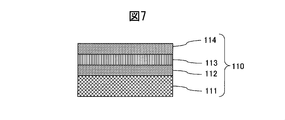
- the cross-sectional schematic diagram of the decoration member 110 of a prior art example is shown.
- the cross-sectional schematic diagram of the hard decoration member of Example 2 is shown.
- a comparison of the scratch resistance of the hard decorative member of Example 2 is shown.
- the cross-sectional schematic diagram of the hard decoration member of Example 3 is shown.
- the comparison of the film hardness of the alloy nitride film produced by changing the amount of nitrogen gas is shown.
- a comparison of brightness of alloy nitride films produced by changing the amount of nitrogen gas is shown.
- a comparison of the saturation of alloy nitride films produced by changing the amount of nitrogen gas is shown.
- the comparison of the flaw resistance of the hard decoration member of Example 3 is shown.
- the cross-sectional schematic diagram of the hard decoration member of Example 4 is shown.
- the comparison of the film hardness of the alloy nitride film produced by changing the amount of nitrogen gas is shown.
- a comparison of brightness of alloy nitride films produced by changing the amount of nitrogen gas is shown.
- a comparison of the saturation of alloy nitride films produced by changing the amount of nitrogen gas is shown.
- the comparison of the flaw resistance of the hard decoration member of Example 4 is shown.
- the cross-sectional schematic diagram of the hard decoration member of Example 5 is shown.
- the comparison of the film hardness of the alloy carbide film produced by changing the amount of methane gas is shown.
- a comparison of brightness of alloy carbide films produced by changing the amount of methane gas is shown.
- a comparison of the saturation of alloy carbide films produced by changing the amount of methane gas is shown.
- a comparison of the scratch resistance of the hard decorative member of Example 5 is shown.
- An abrasion resistant layer 12 made of a carbide of CrMo alloy is formed on the surface of a SUS316L base material 11 as a base material.
- the hard decorative member of the present invention employs an alloy film
- the adhesion performance, film hardness, scratch resistance, wear resistance, color tone, and corrosion resistance can be freely controlled by the ratio of each metal constituting the alloy. It has the feature that it can.
- the hardness, brightness, and saturation of the hard decorative member 10 can be changed according to the required characteristics.
- the carbon content indicates the maximum hardness.
- the hardness is adjusted accordingly. It is possible to adjust the carbon content.
- the hard decorative member of the present invention solves the problems of the prior art.
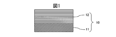
- the hard decorative member 10 of the present invention is formed of a base material 11 and an abrasion resistant layer 12 formed on the surface of the base material 11. ⁇ Base material>
- the base material 11 is preferably a base material formed from metal or ceramics.
- the metal including alloy
- the metal include stainless steel, titanium, titanium alloy, copper, copper alloy, tungsten or hardened stainless steel, titanium, and titanium alloy. These metals can be used alone or in combination of two or more. Further, the shape of the substrate 11 is not limited. ⁇ Abrasion resistant layer>
- the wear resistant layer 12 is made of Cr, an alloy of one or more selected from the group consisting of Mo, W, Nb, Ta, Ti, Hf, Zr and V, and one of nitrogen, carbon and oxygen. It is formed from a reaction compound with a seed or two or more nonmetallic elements. The material to be selected is determined by the desired appearance color and the usage environment of the coating. In addition to the above metals, the alloy may contain metals such as B, Al, Si, Mn, Co, La, Ce, Y, and Sc within a total of 5 Wt% in the ratio of the alloy.
- the content of carbon, nitrogen or mixed elements in the wear resistant layer is 0 to 70 atm%.
- the thickness of the wear-resistant layer is preferably 0.2 to 4 ⁇ m.
- the hardness is desirably HV2000 or higher. Since the scratch resistance performance is approximately dependent on the film thickness and film hardness of the wear resistant layer, the film thickness is preferably 0.2 ⁇ m or more in order to improve the scratch resistance and wear resistance, and the film hardness should be as small as possible. It is desirable to raise it. However, if the film thickness exceeds 4 ⁇ m, there is a high risk of cracking and peeling due to an increase in film stress, which is disadvantageous in terms of cost. Therefore, the film thickness is preferably 4 ⁇ m or less. ⁇ Manufacturing method>
- Each layer constituting the hard decorative member of the present invention can be formed by a sputtering method, an ion plating method, or the like, but is preferably formed by a reactive sputtering method.
- the hard decorative member 10 is manufactured by a reactive sputtering method.
- an inert gas mainly Ar gas
- a DC or AC high voltage is applied between the substrate and the target composed of the constituent atoms of the coating to ionize the substrate.
- Ar is collided with a target to form a repelled target material on a substrate.
- a trace amount of reactive gas together with the inert gas, a compound film of target constituent atoms and reactive gas can be formed on the substrate.
- the decorative member 10 of the embodiment is manufactured by controlling adhesion, film hardness, and color tone by adjusting the selection and amount of target constituent atoms and reactive gases.
- the reactive sputtering method has high controllability of film quality and film thickness and is easy to automate. Further, since the energy of the sputtered atoms is high, it is not necessary to heat the substrate for improving adhesion, and a film can be formed even on a substrate such as a plastic having a low melting point. In addition, since the target material that has been blown off is formed on the substrate, it is possible to form a film even with a high melting point material, and the material can be freely selected. Furthermore, a carbide film, a nitride film, a carbonitride film, an oxynitride film, an oxycarbide film, an oxynitride carbide film, and the like can be easily formed by selecting and mixing reactive gases.
- alloy films alloy carbide films, nitride films, carbonitride films, oxynitride films, oxycarbide films, oxynitride carbide films, etc. Become.
- the timepiece provided by the present invention is characterized by having the above-described hard decorative member in a part of its constituent parts, for example, an exterior part.
- the timepiece may be any of a photovoltaic power generation timepiece, a thermoelectric generation timepiece, a radio wave reception type self-correcting timepiece, a mechanical timepiece, and a general electronic timepiece.
- Such a timepiece is manufactured by a known method using the hard decorative member. Watches are easily scratched by rubbing against a shirt or colliding with a desk or wall.
- the hard decorative member described above can be used for a bezel, a lug, a case, a crown, a push button, a band, and the like of a watch.
- the film hardness was measured using a micro indentation hardness tester (H100 manufactured by FISCHER). A Vickers indenter was used as a measuring element. The Vickers indenter was inserted into the sample with a 5 mN load, held for 10 seconds, then unloaded, and the film hardness was calculated from the depth of the indent formed by the insertion of the Vickers indenter. ⁇ Scratch resistance test method>
- the scratch resistance test is carried out as follows. A decorative film is applied to a SUS316L base material defined in JIS, and a worn paper in which alumina particles are uniformly dispersed is brought into contact with a test sample at a constant load, and scratches are generated by rubbing a predetermined number of times. The surface of the test sample with scratches was scanned in the direction perpendicular to the scratch direction, the surface roughness was measured, and the scratch resistance was evaluated as the mean square roughness. The greater the amount of scratches, the deeper the depth of the scratches, the larger the mean square roughness value. Conversely, the smaller the amount of scratches, the smaller the scratch depth, the smaller the mean square roughness value. Therefore, the scratch resistance can be numerically evaluated by this scratch resistance test. ⁇ Corrosion resistance test method>
- the CASS test is a test in accordance with JIS-H 8502, where the sample is placed in an atmosphere in which cupric chloride is added to an acetic acid-acidic sodium chloride solution for 48 hours to peel off the decorative film. And a test for evaluating the corrosion resistance by observing discoloration.
- the artificial sweat test is a test compliant with ISO12870. A sample is placed in an atmosphere in which sodium chloride and lactic acid are mixed (artificial sweat) for 48 hours at 55 ° C, and the degree of discoloration of the decorative film is observed. This is a test for evaluating the corrosion resistance.
- the sample was immersed in a 5% aqueous sodium hydroxide solution at 30 ° C. for 24 hours, and the corrosion resistance was evaluated by observing peeling and discoloration of the decorative film.
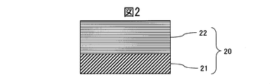
- Example 1 a sintered body of Cr 50 Wt% Mo50 Wt% was used as a sputtering target. As shown in FIG. 2, a CrMo alloy carbide film having a thickness of 1.8 ⁇ m using a SUS316L material defined in JIS as a base material 21 and a sputtering method using an Ar gas with a flow rate of 105 sccm and a flow rate of 30 sccm. was formed on the base material 21, and the hard decorative member 20 was produced.
- FIG. 3 is a diagram comparing the film hardness of a CrMo alloy carbide film produced by changing the amount of methane gas with the film hardness of a Cr carbide film and a Mo carbide film. It can be seen that the CrMo alloy carbide film clearly shows a higher hardness than the Cr carbide film, and also shows a high hardness that is not inferior to that of the Mo carbide film.
- Scratch resistance is roughly determined by the product of the hardness of the abrasion-resistant layer, the thickness of the abrasion-resistant layer, the adhesion to the substrate, and the hardness of the substrate, so the film was formed thick under the highest hardness conditions. Better. Therefore, from the viewpoint of film hardness, the Mo carbide film is superior to the CrMo alloy carbide film. However, as described later, the Mo carbide film cannot maintain the performance as an exterior component because the corrosion resistance is not sufficient. There are drawbacks. In addition, since the film hardness of the Cr carbide film is lower than HV2000, sufficient scratch resistance performance cannot be expected.
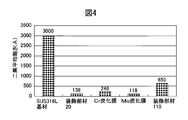
- FIG. 4 shows a SUS316L base material having no Mo carbide film, Cr carbide film, and hard film formed with the same film thickness as the flaw resistance of the decorative member 20 produced in Example 1, and Patent Document 1 shown in FIG. It is the figure compared with the decoration member 110 (the outermost layer is Pt) produced based on this.
- FIG. 4 shows that the Mo carbide film having a high film hardness has the highest scratch resistance and the Cr carbide film has the lowest scratch resistance, which is clearly a result derived from the film hardness. Since the CrMo alloy carbide film has both characteristics of Cr and Mo, it can be seen that the CrMo alloy carbide film clearly shows higher scratch resistance than the Cr carbide film although it does not reach the Mo carbide film.
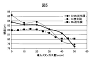
- FIG. 5 is a diagram comparing the brightness of films prepared by changing the amount of methane gas in a CrMo alloy carbide film. It can be seen that the CrMo alloy carbide film clearly shows a high brightness as compared with the Mo carbide film, and also shows a high brightness which is not inferior to that of the Cr carbide film.
- High brightness is required for high-quality decorations. Therefore, from the viewpoint of brightness, the region where the amount of methane gas is small in the Cr carbide film is the most excellent. However, as can be seen from FIG. 3, the hardness of the Cr carbide film in that region is low, and sufficient scratch resistance cannot be obtained. It can be seen that a decorative member having high hardness can be obtained while maintaining high brightness by alloying Cr and Mo.
- FIG. 6 is a diagram comparing the saturation (C *) of films prepared by changing the amount of methane gas in a CrMo alloy carbide film.
- the chroma of the CrMo alloy carbide film showed an almost intermediate value between the Cr carbide film and the Mo carbide film. Since the appearance color of the CrMo hard decorative member 20 is: L *: 82.16, a *: 0.57, b *: 1.69, the appearance color of the SUS316L base material, L *: 85.1, a *: Compared to 0.38, b *: 2.34, it can be seen that the colors are almost the same.
- Table 1 shows the hardness, corrosion resistance, and overall evaluation of the carbide film, nitride film, and carbonitride film with respect to the alloy ratio of Cr and Mo. As seen in Table 1, it can be seen that the maximum hardness and corrosion resistance change according to the alloy ratio, and it is possible to freely adjust them according to the alloy ratio. Increasing the Mo ratio increases the film hardness and is advantageous for scratch resistance. However, if the Mo ratio is 100 wt%, or if the Mo ratio is high, the corrosion resistance in the CAS test is poor and applied as a decorative member. It is not possible. Further, when the Cr ratio is high, the brightness and corrosion resistance are high, but since the film hardness is low, the scratch resistance is deteriorated and cannot be applied as a decorative member.
- the Cr ratio is preferably 20 wt% or more, and more preferably 30 Wt% or more.
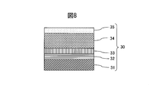
- Example 2 a sintered body of Cr50 Wt% Mo50 Wt% was used as a sputtering target in the same manner as in Example 1.
- a SUS316L material defined in JIS was used as the base material 31, and an adhesion layer 32 made of a lower oxide of CrMo alloy was formed on the base material 31 by sputtering.
- the methane gas was gradually increased while introducing a small amount of oxygen gas, thereby forming the gradient adhesion layer 33 of the CrMo alloy oxycarbide film by 0.2 ⁇ m.
- a thin wear-resistant layer 34 made of a CrMo alloy carbide film was formed to 2.0 ⁇ m.
- the color-decreasing inclined layer 35 of the CrMo alloy carbide film was formed to have a thickness of 0.1 ⁇ m, and the hard decorative member 30 was manufactured.
- the appearance color of the hard decorative member 30 obtained in Example 2 is L *: 83.74, a *: 0.37, b *: 0.51 according to the Lab color space display, and the SUS316L base material 21 Appearance color, L *: 85.1, a *: 0.38, b *: 2.34.
- the inclined adhesion layer 33 was formed by increasing the amount of methane gas introduced in FIG. 3 from 0 sccm to 40 sccm indicating the maximum hardness while introducing oxygen gas at 3 sccm, thereby forming a 0.2 ⁇ m CrMo alloy carbide film.
- a CrMo alloy carbide film having a thickness of 2.0 ⁇ m was formed under the condition that the introduced amount of methane gas showing the maximum hardness was 40 sccm.
- As the color-raising inclined layer 35 a CrMo alloy carbide film in which the methane gas introduction amount showing the maximum hardness in FIG. 3 was gradually decreased from 40 sccm to 0 sccm was formed in a thickness of 0.1 ⁇ m.
- the base material and the adhesion layer can be integrated.
- the inclined adhesion layer ensures sufficient adhesion between the adhesion layer and the wear-resistant layer, and the structure increases the film stress in an inclined manner.
- the scratch resistance and wear resistance are improved, and a thick wear-resistant layer having high film hardness can be formed. Scratch resistance is roughly determined by the product of the hardness of the wear-resistant layer, the film thickness of the wear-resistant layer, and the degree of adhesion to the base material, so the scratch resistance is improved by improving the adhesion to the base material. be able to.
- the color-raising inclined layer 35 in the hard decorative member 30 of Example 2 by increasing the carbon content in an inclined manner, as shown in FIG. 5 and FIG. And the appearance color of the hard decorative member 30 can be brought close to the SUS316L material that is the base material. Further, the color-raising gradient layer 35 has high adhesion with the wear-resistant layer 34. Therefore, the color-raising inclined layer 35 contributes to the effect that scratches are not noticeable, and is difficult to peel off even if scratches are made.
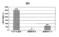
- FIG. 9 is a diagram showing the scratch resistance performance of the hard decorative member 30 of Example 2. Scratch resistance of the decorative member 110 (the outermost layer is Pt) manufactured based on Patent Document 1 shown in FIG. 7, the hard decorative member 30 of Example 2 according to the present invention, and the SUS316L base material on which no hard film is formed ( The results of measuring the root mean square roughness are shown in FIG. 9 for comparison.
- the hard decorative member 30 of Example 2 of the present invention has much better scratch resistance than the SUS316L base material on which the hard film is not formed and the decorative member 110 manufactured based on Patent Document 1.
- the film stress increases or decreases in a gradient manner, so that the effect of suppressing the generation of cracks and peeling due to stress strain can be obtained, and the scratch resistance and wear resistance As a result, the brightness is increased in the Lab color space display in an inclined manner due to the presence of the color-increasing inclined layer, so that it is possible to provide a more luxurious decorative member.
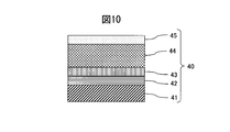
- Example 3 a sintered body of Cr 50 wt% Nb 50 wt% was used as a sputtering target.
- a SUS316L material defined in JIS was used as the base material 41, and an adhesion layer 42 made of a lower oxide of a CrNb alloy was formed on the base material 41 by a sputtering method.
- the nitrogen gas was gradually increased while introducing a small amount of oxygen gas, thereby forming 0.2 ⁇ m of the gradient adhesion layer 43 of the CrNb alloy oxynitride film.
- a thin wear-resistant layer 44 made of a CrNb alloy nitride film was formed to 1.8 ⁇ m.
- the nitrogen gas was decreased in an inclined manner to form a colored gradient layer 45 of a CrNb alloy nitride film having a thickness of 0.1 ⁇ m, and the hard decorative member 40 was manufactured.
- the appearance color by the Lab color space display of the hard decorative member 40 obtained in Example 3 is L *: 83.37, a *: 0.05, b *: 0.61, and the appearance color of the SUS316L base material 41 , L *: 85.1, a *: 0.38, b *: 2.34.
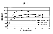
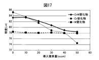
- FIG. 11 shows a comparison between the hardness change of the hard decorative member 40 of Example 3 and the hardness change of the Cr nitride film and the Nb nitride film when the amount of introduced nitrogen gas is changed while the amount of Ar gas is constant at 105 sccm.
- FIG. The hardness change of the hard decorative member 40 had a peak, and the hard decorative member 40 showed the maximum hardness under the condition of a nitrogen gas amount of 30 sccm.
- the CrNb alloy nitride film clearly shows a high hardness compared to the Cr nitride film, and also shows a high hardness that is not inferior to that of the Nb nitride film.
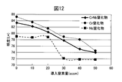
- FIG. 12 is a diagram showing a change in brightness of the CrNb alloy nitride film when the amount of introduced nitrogen gas is changed, compared with that of the Cr nitride film and the Nb nitride film.
- the CrNb alloy nitride film clearly shows a high brightness as compared with the Nb nitride film, and also shows a high brightness that is not inferior to the Cr nitride film.
- High brightness is required for high-quality decorations. Therefore, from the viewpoint of lightness, it can be said that the region with a small amount of nitrogen gas in the Cr nitride film is the most excellent. However, as can be seen from FIG. 11, the hardness of the Cr nitride film in that region is low, and sufficient scratch resistance cannot be obtained. By decorating Cr and Nb, a decorative member having high hardness while maintaining high brightness can be obtained.
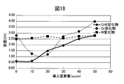
- FIG. 13 is a diagram showing a change in the saturation of the CrNb alloy nitride film when the amount of introduced nitrogen gas is changed in comparison with the change in the saturation of the Cr nitride film and the Nb nitride film.
- the saturation of the CrNb alloy nitride film is lower than that of the Cr nitride film and the Nb nitride film in the low nitrogen gas region and higher than that of the Cr nitride film and the Nb nitride film in the high nitrogen gas region.
- the saturation (C *) is close to 0, it can be seen that the CrNb alloy nitride film shows a color closer to white particularly in the low nitrogen gas region.
- a CrNb lower oxide film was formed by introducing 5 sccm of oxygen gas under the condition of nitrogen gas introduction amount 0 sccm of FIG.
- the adhesion of the adhesion layer 42 to the base material becomes higher than that of the CrNb alloy film, and the scratch resistance of the adhesion layer 42 can be improved.
- a CrNb alloy nitride film having a thickness of 0.2 ⁇ m was formed by increasing the nitrogen gas introduction amount in FIG.
- a CrNb alloy nitride film was formed with a thickness of 1.8 ⁇ m under the condition of a nitrogen gas introduction amount indicating the maximum hardness of 30 sccm.
- a CrNb alloy nitride film was formed to have a thickness of 0.1 ⁇ m by gradually decreasing the nitrogen gas introduction amount from 30 sccm to 0 sccm, which shows the maximum hardness in FIG.
- the inclined adhesion layer 43 in the hard decorative member 40 of Example 3 eliminates a clear interface between the adhesion layer and the wear-resistant layer, the base material and the adhesion layer can be integrated.
- the inclined adhesion layer ensures sufficient adhesion between the adhesion layer and the wear-resistant layer, and the film stress increases in a gradient manner, thus suppressing the occurrence of cracks and delamination due to stress strain. As a result, the scratch resistance and wear resistance are improved, and a thick wear-resistant layer having high film hardness can be formed.
- Scratch resistance is roughly determined by the product of the hardness of the wear-resistant layer, the thickness of the wear-resistant layer, and the degree of adhesion to the base material, so that the scratch resistance is improved by improving the adhesion to the base material. be able to.
- the color-raising gradient layer 45 in the hard decorative member 40 of Example 3 decreases the nitrogen content in an inclined manner, thereby increasing the L * and C * in the Lab color space display as seen in FIGS. And the appearance color of the hard decorative member 40 can be brought close to the SUS316L material that is the base material.
- the color raising gradient layer 45 has high adhesion to the wear resistant layer 44. Therefore, the color-raising inclined layer 45 contributes to the effect that scratches are not conspicuous, and does not easily peel off even if scratches occur.
- FIG. 14 is a diagram showing the results of measuring the scratch resistance performance of the hard decorative member 40 of Example 3.
- the measured results are shown in FIG. 14 for comparison.
- the hard decorative member 40 of Example 3 of the present invention has much better scratch resistance than the SUS316L base material not formed with a hard film and the decorative member 110 manufactured based on Patent Document 1. 14 confirmed.
- Table 2 shows the hardness, corrosion resistance performance, and overall evaluation of the carbide film, nitride film, and carbonitride film with respect to the alloy ratio of Cr and Nb.
- Table 2 shows the hardness, corrosion resistance performance, and overall evaluation of the carbide film, nitride film, and carbonitride film with respect to the alloy ratio of Cr and Nb.
- the maximum hardness and corrosion resistance change according to the alloy ratio, and it is possible to freely adjust these characteristics according to the alloy ratio.
- Increasing the Cr ratio increases the brightness, improves the adhesion to the substrate, and enables the formation of a thick film, which is advantageous for scratch resistance.
- the Cr ratio is 100 wt%, the film hardness Therefore, high scratch resistance cannot be obtained.
- the Nb ratio is high, the film hardness increases, which is advantageous for scratch resistance.
- the Cr ratio is desirably 20 wt% or more, and more desirably 30 wt% or more.
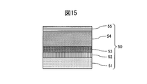
- Example 4 a sintered body of Cr 50 wt% W 50 wt% was used as a sputtering target.
- a JIS type 2 Ti base material was used as the base material 51, and an adhesion layer 52 made of a lower oxide of a CrW alloy was formed on the base material 51 by sputtering.
- the gradient adhesion layer 53 of the CrW alloy oxynitride film was formed to have a thickness of 0.2 ⁇ m by gradually increasing the nitrogen gas while introducing a small amount of oxygen gas.
- a thin wear-resistant layer 54 made of a CrW alloy nitride film was formed to 1.8 ⁇ m.
- the nitrogen gas was decreased in an inclined manner to form a colored gradient layer 55 of CrW alloy nitride film having a thickness of 0.15 ⁇ m, and the hard decorative member 50 was manufactured.
- the appearance color of the hard decorative member 50 obtained in Example 4 is L *: 83.42, a *: 0.1, b *: 0.64 by Lab color space display, and the appearance of the SUS316L base material 41.
- the colors are almost the same as L *: 85.1, a *: 0.38, b *: 2.34.
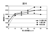
- FIG. 16 shows a comparison of the hardness change of the Cr nitride film and the W nitride film when the amount of introduced nitrogen gas is changed in the hard decorative member 50 of Example 4 when the Ar gas amount is constant at 105 sccm.
- FIG. The film hardness increased according to the amount of nitrogen gas introduced, and the maximum hardness was exhibited under the condition of a nitrogen gas amount of 50 sccm.
- the CrW alloy nitride film clearly shows a higher hardness than the Cr nitride film, and also shows a high hardness that is not inferior to the W nitride film.
- FIG. 17 is a diagram showing a change in brightness when the amount of introduced nitrogen gas is changed in comparison with a change in brightness of the Cr nitride film and the W nitride film.
- the CrW alloy nitride film clearly shows higher brightness than the W nitride film, and shows higher brightness than the Cr nitride film in the high nitrogen gas region.
- High brightness is required for high-quality decorations. Therefore, from the viewpoint of lightness, it can be said that the region where the ratio of Cr is 100 wt% and the amount of nitrogen gas is small is most excellent. However, as can be seen from FIG. 17, the hardness of the Cr nitride film in that region is low, and sufficient scratch resistance cannot be obtained. By alloying Cr and W, a decorative member having high hardness while maintaining high brightness can be obtained.
- FIG. 18 is a diagram showing the change in saturation when the amount of introduced nitrogen gas is changed in comparison with the change in saturation of the Cr nitride film and the W nitride film.
- the saturation of the CrW alloy nitride film was lower than the saturation of the Cr nitride film and the W nitride film.
- the saturation (C *) is close to 0, it can be seen that the CrW alloy nitride film shows a color closer to white particularly in the low nitrogen gas region.
- 0.1 ⁇ m of CrW lower oxide film was formed by introducing 5 sccm of oxygen gas under the condition of nitrogen gas introduction amount 0 sccm of FIG.
- the adhesion of the film to the substrate becomes higher than that of the CrW alloy film, thereby improving the scratch resistance.
- the inclined adhesion layer 53 while introducing 3 sccm of oxygen gas, the amount of nitrogen gas introduced in FIG. 16 was increased from 0 sccm to 50 sccm showing the maximum hardness, thereby forming a CrW alloy nitride film having a thickness of 0.2 ⁇ m.
- a CrW alloy nitride film having a thickness of 1.8 ⁇ m was formed under the condition of a nitrogen gas introduction amount indicating the maximum hardness of 50 sccm.
- a CrW alloy nitride film was formed in an amount of 0.15 ⁇ m by decreasing the nitrogen gas introduction amount 50 sccm showing the maximum hardness in FIG.
- the inclined adhesion layer 53 in the hard decorative member 50 of Example 4 eliminates a clear interface between the adhesion layer and the wear-resistant layer, the base material and the adhesion layer can be integrated.
- the base material and the adhesion layer can be integrated.
- an inclined adhesion layer sufficient adhesion between the adhesion layer and the wear-resistant layer is ensured, and since the film stress increases in a gradient manner, generation of cracks due to stress strain and suppression of delamination are suppressed.
- the scratch resistance and wear resistance are improved, and a wear layer having a high film hardness can be formed thickly. Scratch resistance is roughly determined by the product of the hardness of the wear-resistant layer, the thickness of the wear-resistant layer, and the degree of adhesion to the base material. Therefore, the scratch resistance is improved by improving the adhesion to the base material. Can be made.
- the color-raising gradient layer 55 in the hard decorative member 50 of Example 4 is formed by increasing the L * and C * in the Lab color space display as shown in FIGS. 17 and 18 by decreasing the nitrogen content in an inclined manner. Can be performed in an inclined manner, and the appearance color of the hard decorative member 50 can be brought close to the SUS316L material as the base material.
- the color raising gradient layer 55 has high adhesion to the wear resistant layer 54. Therefore, the color-raising inclined layer 55 contributes to the effect that scratches are not noticeable, and is difficult to peel off even if scratches are made.
- FIG. 19 is a diagram showing the results of measuring the scratch resistance performance of the hard decorative member 50 of Example 4. Scratch resistance of the decorative member 110 (the outermost layer is Pt) manufactured based on Patent Document 1 shown in FIG. 7, the hard decorative member 50 of Example 4 according to the present invention, and the SUS316L base material on which no hard film is formed ( The result of measuring the root mean square roughness is shown as a comparison. From FIG. 19, the hard decorative member 50 of Example 4 of the present invention has much better scratch resistance performance than the SUS316L base material on which the hard film is not formed and the decorative member 110 manufactured based on Patent Document 1. It was confirmed.
- Table 3 shows the hardness, corrosion resistance, and comprehensive evaluation of the carbide film, nitride film, and carbonitride film with respect to the alloy ratio of Cr and W.
- the maximum hardness and corrosion resistance change according to the alloy ratio, and it is possible to freely adjust them according to the alloy ratio.
- Increasing the Cr ratio increases the brightness, improves the adhesion with the base material and enables a thick film, which is advantageous for scratch resistance, but when the Cr ratio is 100 wt%, the film hardness is low, High scratch resistance cannot be obtained.
- the W ratio is high, the film hardness is high and it is advantageous for scratch resistance.
- the lightness is low and the resistance to hypochlorous acid is poor, it cannot be applied to a decorative member.
- the Cr ratio is desirably 20 wt% or more, and more desirably 30 wt% or more.
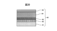
- Example 5 a sintered body of Cr 40 wt% Ti 60 wt% was used as a sputtering target in FIG.
- a JIS type 2 Ti base material was used as the base material 61, and an adhesion layer 62 made of a lower oxide of a CrTi alloy was formed on the base material 61 by a sputtering method.
- methane gas was increased in a gradient while introducing a small amount of oxygen gas, thereby forming 0.2 ⁇ m of the gradient adhesion layer 63 of the CrTi alloy oxycarbide film.
- a 1.7 ⁇ m thin wear-resistant layer 64 made of a CrTi alloy carbide film was formed.
- the methane gas was decreased in an inclined manner to form a colored gradient layer 65 of a CrTi alloy carbide film with a thickness of 0.1 ⁇ m, thereby producing a hard decorative member 60.
- the appearance color by the Lab color space display of the hard decorative member 60 obtained in Example 5 is L *: 82.34, a *: 0.97, b *: 0.77, and the appearance color of the SUS316L base material 41 , L *: 85.1, a *: 0.38, b *: 2.34.
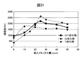
- FIG. 21 is a diagram in which the hardness change when the amount of introduced methane gas is changed and the hardness change of the Cr carbide film and the Ti carbide film are compared with the hardness change of the Cr carbide film and the Ti carbide film in the hard decorative member 60 of Example 5 with a constant Ar gas amount of 105 sccm. Show.
- the hardness change had a hardness peak, and the hardness change of the Ti carbide film showed the maximum hardness under the condition of a methane gas amount of 25 sccm.
- the CrTi alloy carbide film clearly showed a higher hardness in the high methane gas region than the Cr carbide film.
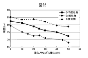
- FIG. 22 is a diagram showing a change in brightness when the amount of introduced methane gas is changed in comparison with a change in brightness of a Cr carbide film and a Ti carbide film.
- the brightness of the CrTi alloy carbide film is approximately intermediate between the brightness of the Cr carbide film and the brightness of the Ti carbide film, and is clearly higher than that of the Ti carbide film.
- High brightness is required for high-quality decorations. Therefore, from the viewpoint of lightness, it can be said that the region where the ratio of Cr is 100 wt% and the amount of methane gas is small is most excellent. However, as can be seen from FIG. 21, the hardness of the Cr carbide film in that region is low, and sufficient scratch resistance cannot be obtained. By alloying Cr and Ti, a decorative member having high hardness while maintaining high brightness can be obtained.
- FIG. 23 is a diagram showing the change in saturation when the amount of introduced methane gas is changed in comparison with the change in saturation of the Cr carbide film and Ti carbide film.
- the saturation of the CrTi alloy carbide film was approximately an intermediate value between the saturation of the Cr carbide film and the saturation of the Ti carbide film, and the lowest value was obtained when the methane gas was 10 sccm. In the case of white, since the saturation (C *) is close to 0, the CrTi alloy carbide film shows a color closer to white particularly in the low methane gas region.
- a CrTi lower oxide film was formed by introducing 5 sccm of oxygen gas under the condition of 0 sccm of methane gas introduced in FIG.
- the adhesion to the substrate can be made higher than that of the CrTi alloy film, and the scratch resistance can be improved.
- the inclined adhesion layer 63 while introducing 3 sccm of oxygen gas, the amount of methane gas introduced in FIG.
- a CrTi alloy carbide film having a thickness of 0.2 ⁇ m As the wear resistant layer 64, a CrTi alloy carbide film having a maximum hardness of 1.7 scm was formed under the condition of a methane gas introduction amount of 25 sccm. As the color-inclined inclined layer 65, a CrTi alloy carbide film was formed to have a thickness of 0.1 ⁇ m by decreasing the methane gas introduction amount 25 sccm showing the maximum hardness of FIG. 21 from 0 sccm to 0 sccm.
- the inclined adhesion layer 63 in the hard decorative member 60 of Example 5 eliminates a clear interface between the adhesion layer and the wear-resistant layer, the base material and the adhesion layer can be integrated.
- the inclined adhesion layer ensures sufficient adhesion between the adhesion layer and the wear-resistant layer, and the film stress increases in a gradient manner, thus suppressing the occurrence of cracks and delamination due to stress strain. As a result, the scratch resistance and wear resistance are improved, and a thick wear-resistant layer having high film hardness can be formed.
- Scratch resistance is roughly determined by the product of the hardness of the wear-resistant layer, the film thickness of the wear-resistant layer, and the degree of adhesion to the base material, and thus improves the scratch resistance by improving the adhesion to the base material. be able to.
- the color raising gradient layer 65 in the hard decorative member 60 of Example 5 decreases the carbon content in an inclined manner, thereby increasing the L * and the C * in the Lab color space display as seen in FIGS. And the appearance color of the hard decorative member 60 can be brought close to the SUS316L material that is the base material.
- the color raising gradient layer 65 has high adhesion to the wear resistant layer 64. Therefore, the color-raising inclined layer 65 contributes to the effect that scratches are not conspicuous, and is difficult to peel off even if scratches occur.
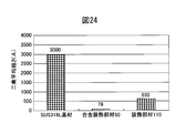
- FIG. 24 is a diagram showing the results of measuring the scratch resistance performance of the hard decorative member 60 of Example 5.
- the decorative member 110 (the outermost layer Pt) produced based on Patent Document 1 shown in FIG. 7, the hard decorative member 60 of Example 5 according to the present invention, and the scratch resistance of the SUS316L base material on which no hard film is formed.
- the result of having measured (root mean square roughness) is shown.
- the hard decorative member 60 of Example 5 of the present invention has far more scratch resistance than the decorative member 110 produced based on the SUS316L base material and Patent Document 1 in which the hard film is not formed. It was confirmed that it was good.
- Table 4 shows the hardness, corrosion resistance, and overall evaluation of the carbide film with respect to the alloy ratio of Cr and Ti. Since the 4A group such as Ti, Hf, and Zr exhibits a gold color when the nitride film is formed, the alloy is limited to the carbide film when the 4A group is alloyed. As can be seen in Table 4, the maximum hardness and corrosion resistance change according to the alloy ratio, and it is possible to freely adjust them according to the alloy ratio. Increasing the Cr ratio increases the brightness. When the Cr ratio is increased, the adhesion to the substrate is improved and the thick film can be formed, which is advantageous for scratch resistance. However, when the Cr ratio is 100 wt%, the film hardness is low and the scratch resistance is high. Cannot be obtained.
- the Cr ratio is desirably 20 wt% or more.
- the present invention it is possible to provide a hard decorative member that suppresses deterioration in appearance quality due to scratches or wear and has a high-grade color tone, and further provides film hardness, scratch resistance performance, abrasion resistance performance, color tone resistance, Since it is possible to provide products that can freely control the corrosion performance, the industrial applicability is high.
- Hard decoration member of embodiment of this invention 11 Base material 12 Wear-resistant layer 110 Decoration member of conventional example (made based on patent document 1) 111 Base material 112 Adhesion layer 113 Wear-resistant layer 114 Pt layer 20 Example 1 Hard decorative member 21 SUS316L base material 22 CrMo alloy wear-resistant layer 30 Hard decorative member of Example 2 31 SUS316L base material 32 CrMo alloy lower oxide film adhesion layer 33 CrMo alloy oxycarbide film gradient adhesion layer 34 CrMo alloy carbide film Wear-resistant layer 35 CrMo alloy carbide film Color-increasing gradient layer 40 Hard decorative member of Example 3 41 SUS316L base material 42 CrNb alloy lower oxide film adhesion layer 43 CrNb alloy oxynitride film gradient adhesion layer 44 CrNb alloy nitride film Abrasion-resistant layer 45 CrNb alloy nitride film Color-raising gradient layer 50 Hard decoration of Example 4 Material 51 Ti base material 52 CrW alloy lower oxide film adhesion layer 53 Cr
Landscapes
- Chemical & Material Sciences (AREA)
- Engineering & Computer Science (AREA)
- Organic Chemistry (AREA)
- Materials Engineering (AREA)
- Mechanical Engineering (AREA)
- Metallurgy (AREA)
- Chemical Kinetics & Catalysis (AREA)
- Inorganic Chemistry (AREA)
- Manufacturing & Machinery (AREA)
- Physics & Mathematics (AREA)
- General Physics & Mathematics (AREA)
- Ceramic Engineering (AREA)
- Physical Vapour Deposition (AREA)
- Adornments (AREA)
Abstract
Provided is a rigid decorative member having high film hardness, excellent scratch resistance properties and abrasion resistance properties, and excellent color tones of brightness and color saturation. This rigid decorative member is characterized by the formation, upon a substrate, of a reaction compound film of: an alloy of Cr and at least one type of metal selected from Mo, W, Nb, Ta, Ti, Hf, Zr, and V; and a non-metal element selected from at least one or type from among nitrogen, carbon, and oxygen. Provided is the rigid decorative member which has dramatically improved scratch resistance and abrasion resistance, has a high-grade color tone, and whereby a product having brightness and color saturation color tones that can be freely controlled is supplied. This rigid decorative member is configured from a reaction compound film of: an alloy of Cr, being a metal having high adhesion to metal and high brightness but having low hardness, and a metal (Mo, W, Nb, Ta, Ti, Hf, Zr, or V) having high film hardness and corrosion resistance, but having low brightness and adhesion; and a non-metal element such as nitrogen, carbon, or oxygen.
Description
本発明は、時計の外装部品、眼鏡やアクセサリーなどの装身具、装飾品などの金属色を有する装飾部材及びスポーツ用品に関するものであり、特に、明度が高く、高級感のある色感と、長期間にわたり耐傷性、耐摩耗性、耐腐蝕性に優れる白色又はステンレス色の硬質装飾部材に関するものである。
The present invention relates to a decorative member having a metallic color, such as an exterior part of a watch, accessories such as glasses and accessories, and a decorative article, and sports equipment, and in particular, has a high brightness and a high-quality color feeling for a long time. The present invention relates to a white or stainless steel hard decorative member having excellent scratch resistance, wear resistance, and corrosion resistance.
従来において、外装部品、眼鏡、アクセサリー、時計などの装身具、装飾品、スポーツ用品などの耐傷性を向上させるための耐磨耗層上には、高級感のある外観とするために最外層に明度の高い白金被膜を形成していた。例えば、特許文献1では、基材上に下地層を形成し、この表面に乾式メッキ法によりTi炭化物膜を形成し、この表面に乾式メッキ法で形成された白金または白金合金からなる装飾被膜を形成している。しかしながら、最外層である白金層は高価なため薄く成膜する必要があり、その薄い白金層が剥離した場合の色変化を抑制するため、Ti炭化物膜を淡い色に作る必要があった。このため、Ti炭化物膜の硬度は本来のTi炭化物膜に比べ硬度が低く(約40%)、十分な耐傷性を得ることができなかった。
Conventionally, on the wear-resistant layer for improving the scratch resistance of exterior parts, eyeglasses, accessories, watches and other accessories, decorations, sports equipment, etc., the outermost layer has a lightness for a high-class appearance. A high platinum film was formed. For example, in Patent Document 1, a base layer is formed on a substrate, a Ti carbide film is formed on this surface by a dry plating method, and a decorative film made of platinum or a platinum alloy formed by a dry plating method is formed on this surface. Forming. However, since the platinum layer as the outermost layer is expensive, it is necessary to form a thin film, and in order to suppress a color change when the thin platinum layer is peeled off, it is necessary to make the Ti carbide film light. For this reason, the hardness of the Ti carbide film is lower than that of the original Ti carbide film (about 40%), and sufficient scratch resistance cannot be obtained.
また、耐傷性を向上させるために、Ti炭化物膜に反応させる炭素量を増やして硬度を増加させると、耐傷性は増加するが色調が暗くなってしまう。また、同様に耐傷性を向上させるために、硬化層であるTi炭化物膜の膜厚を厚くすると、膜応力の増大による膜の剥離や、耐腐食試験において孔食が発生しやすくなるという問題点があり、膜厚を1.0μm以上に成膜することは困難であった。
Also, in order to improve the scratch resistance, if the amount of carbon reacted with the Ti carbide film is increased to increase the hardness, the scratch resistance increases but the color tone becomes dark. Similarly, if the thickness of the Ti carbide film, which is a hardened layer, is increased in order to improve scratch resistance, film peeling due to an increase in film stress and pitting corrosion is likely to occur in the corrosion resistance test. It was difficult to form a film thickness of 1.0 μm or more.
さらに、白金系被膜は人の肌に触れると、アレルギーを引き起こすという問題があった。
Furthermore, there was a problem that platinum-based coatings caused allergies when touched on human skin.
そこで、最外層として、白金系被膜にかえて、明度、色調、低スプラッシュ性が良好で耐傷性を有しかつ高級感を有するMo被膜を使用することが提案されている。しかしながら、Mo被膜は耐食性が低いためそのままでは使用できないという問題があった。また明度、色調、低スプラッシュ性が良好でかつ高級感を有するCr被膜を使用することが提案されているが、Cr被膜は膜硬度が低く十分な耐傷性を得られないこと、また耐食性が非常に高いことから製造工程における剥離が困難であるという問題があった。
Therefore, it has been proposed to use a Mo film having good brightness, color tone, low splash property, scratch resistance, and high-grade feeling instead of the platinum-based film as the outermost layer. However, the Mo film has a problem that it cannot be used as it is because of its low corrosion resistance. In addition, it has been proposed to use a Cr film with good brightness, color tone, low splash, and a high-class feeling, but the Cr film has low film hardness and cannot provide sufficient scratch resistance, and also has very high corrosion resistance. Therefore, there is a problem that peeling in the manufacturing process is difficult.
一方、最外層として、硬度の高く耐食性を有するNb炭化物膜やTa炭化物膜を使用することも提案されているが、基材との密着性が低く膜厚を厚くできないため耐傷性が低く、明度も低いことから、これらの被膜もそのままでは使用できないという問題があった。
On the other hand, it has also been proposed to use an Nb carbide film or a Ta carbide film having high hardness and corrosion resistance as the outermost layer, but since the adhesion with the substrate is low and the film thickness cannot be increased, the scratch resistance is low, and the lightness Therefore, there is a problem that these coatings cannot be used as they are.
本発明の目的は、耐傷性を著しく向上させることにより、傷や磨耗などによる外観品質の低下を抑制し、かつ高級感のある色調を有する硬質装飾部材を提供し、さらに膜硬度、耐傷性能、耐磨耗性能、色調、耐腐食性能を自由にコントロールできる製品を供給することにある。
The object of the present invention is to provide a hard decorative member that suppresses deterioration in appearance quality due to scratches and wear by significantly improving scratch resistance and has a high-grade color tone, and further has film hardness, scratch resistance, The purpose is to supply products that can freely control wear resistance, color, and corrosion resistance.
上記目的を達成するために、本発明の硬質装飾部材は下記に記載の構成を採用する。
In order to achieve the above object, the hard decorative member of the present invention adopts the configuration described below.
(1)基材及び基材上に積層された、Crと、Mo、W、Nb、Ta、Ti、Hf、Zr及びVからなる群から選ばれる1種または2種以上との合金と、窒素、炭素、酸素の1種又は2種以上の非金属元素との反応化合物からなる単層又は複層の硬質装飾皮膜を含む硬質装飾部材。
(2)被膜中の非金属元素は、主として窒素からなる上記(1)に記載の硬質装飾部材。
(3)複層の硬質装飾被膜を含み、複層の硬質装飾被膜が、基板の上に積層された密着層、密着層の上に積層された傾斜密着層、傾斜密着層の上に積層された耐磨耗層、及び耐摩耗層の上に積層された色上げ傾斜層を含み、密着層の非金属元素は低濃度の酸素であり、傾斜密着層、耐磨耗層及び色上げ傾斜層の非金属元素は窒素、炭素、酸素の1種又は2種以上からなり、かつ傾斜密着層を構成する反応化合物における非金属元素の含有量が基板から離れるにつれて厚さ方向に傾斜的に増加し、色上げ傾斜層を構成する反応化合物における非金属元素の含有量が基板から離れるにつれて厚さ方向に傾斜的に増減する上記(1)に記載の硬質装飾部材。
(4)耐磨耗層の厚さは0.5~4μmである上記(3)に記載の硬質装飾部材。
(5)Crの比率が20wt%以上である上記(1)~(4)のいずれかに記載の硬質装飾部材。
(6)硬質装飾部材の外観色が白色またはステンレス色であることを特徴とする上記(1)~(5)のいずれか1項に記載の硬質装飾部材。
(7)少なくとも一部が、(1)~(6)のいずれか1項に記載の硬質装飾部材で構成される外装部品を含む時計。
(8)反応性スパッタリング法により密着層を形成する工程、反応性スパッタリング法により傾斜密着層を形成する工程、反応性スパッタリング法により耐磨耗層を形成する工程、及び反応性スパッタリング法により色上げ傾斜層を形成する工程のうちの少なくとも1つの工程を含む、(1)~(7)のいずれかに記載の硬質装飾部材の製造方法。
(9)傾斜密着層を形成する工程及び色上げ傾斜層を形成する工程の反応性スパッタリング法において使用される非金属元素を含む反応ガスの量が時系列的に増加する上記(8)に記載の硬質装飾部材の製造方法。 (1) A base material and an alloy of Cr and one or more selected from the group consisting of Mo, W, Nb, Ta, Ti, Hf, Zr, and V, and nitrogen laminated on the base material A hard decorative member comprising a single layer or multiple layers of a hard decorative film made of a reactive compound with one or two or more nonmetallic elements of carbon, oxygen.
(2) The hard decorative member according to (1), wherein the nonmetallic element in the coating is mainly composed of nitrogen.
(3) including a multi-layer hard decorative coating, wherein the multi-layer hard decorative coating is laminated on the adhesion layer laminated on the substrate, the gradient adhesion layer laminated on the adhesion layer, and the gradient adhesion layer A wear-resistant layer, and a color-graded gradient layer laminated on the wear-resistant layer, wherein the non-metallic element of the adhesion layer is a low concentration of oxygen, and the gradient adhesion layer, the wear-resistant layer, and the color-gradient gradient layer The non-metallic element is composed of one or more of nitrogen, carbon, and oxygen, and the non-metallic element content in the reaction compound constituting the inclined adhesion layer increases in the thickness direction as the distance from the substrate increases. The hard decorative member according to (1), wherein the content of the nonmetallic element in the reaction compound constituting the color-raising gradient layer increases or decreases in the thickness direction as the distance from the substrate increases.
(4) The hard decorative member according to (3), wherein the wear-resistant layer has a thickness of 0.5 to 4 μm.
(5) The hard decorative member according to any one of (1) to (4), wherein the Cr ratio is 20 wt% or more.
(6) The hard decorative member according to any one of (1) to (5) above, wherein the appearance color of the hard decorative member is white or stainless steel.
(7) A timepiece including an exterior part, at least part of which is composed of the hard decorative member according to any one of (1) to (6).
(8) A step of forming an adhesion layer by a reactive sputtering method, a step of forming an inclined adhesion layer by a reactive sputtering method, a step of forming an abrasion-resistant layer by a reactive sputtering method, and a color increase by a reactive sputtering method The method for manufacturing a hard decorative member according to any one of (1) to (7), including at least one step of forming a gradient layer.
(9) The amount of the reaction gas containing a nonmetallic element used in the reactive sputtering method in the step of forming the gradient adhesion layer and the step of forming the color-gradient gradient layer is increased in time series. Manufacturing method for hard decorative member.
本発明によれば、傷や磨耗などによる外観品質の低下を抑制し、かつ高級感のある色調を有した硬質装飾部材を提供し、さらに膜硬度、耐傷性能、耐磨耗性能、色調、耐腐食性能、エッチング性能を自由にコントロール可能な製品を提供できる。
According to the present invention, it is possible to provide a hard decorative member that suppresses deterioration in appearance quality due to scratches or wear and has a high-grade color tone, and further provides film hardness, scratch resistance performance, abrasion resistance performance, color tone resistance, We can provide products that can freely control corrosion performance and etching performance.
図1を用いて、本発明の硬質装飾部材の構造を説明する。基材としてSUS316L基材11の表面に、CrMo合金の炭化物からなる耐磨耗層12が形成されている。
The structure of the hard decorative member of the present invention will be described with reference to FIG. An abrasion resistant layer 12 made of a carbide of CrMo alloy is formed on the surface of a SUS316L base material 11 as a base material.
本発明の硬質装飾部材では合金膜を採用していることにより、合金を構成するそれぞれの金属の比率により密着性能、膜硬度、耐傷性能、耐磨耗性能、色調、耐腐食性能を自由にコントロールできるという特徴をもつ。
Since the hard decorative member of the present invention employs an alloy film, the adhesion performance, film hardness, scratch resistance, wear resistance, color tone, and corrosion resistance can be freely controlled by the ratio of each metal constituting the alloy. It has the feature that it can.
硬質装飾部材10の硬度、明度、彩度は、求める特性に応じて変化させることが可能であり、耐傷性を求める場合は最大硬度を示す炭素含有量で、高い明度を求める場合にはそれに応じた炭素含有量での調整が可能となる。
The hardness, brightness, and saturation of the hard decorative member 10 can be changed according to the required characteristics. When obtaining scratch resistance, the carbon content indicates the maximum hardness. When obtaining high brightness, the hardness is adjusted accordingly. It is possible to adjust the carbon content.
このようにして、本発明の硬質装飾部材では、従来技術の問題点を解決している。
Thus, the hard decorative member of the present invention solves the problems of the prior art.
本発明の硬質装飾部材10は、基材11と、基材11表面に形成された耐磨耗層12から形成される。
<基材> The harddecorative member 10 of the present invention is formed of a base material 11 and an abrasion resistant layer 12 formed on the surface of the base material 11.
<Base material>
<基材> The hard
<Base material>
上記基材11は、好ましくは金属またはセラミックスから形成される基材である。金属(合金を含む)として、具体的には、ステンレス鋼、チタン、チタン合金、銅、銅合金、タングステンまたは硬質化処理したステンレス鋼、チタン、チタン合金などが挙げられる。これらの金属は、一種単独で、あるいは2種以上組み合わせて用いることができる。また上記基材11の形状については限定されない。
<耐磨耗層> Thebase material 11 is preferably a base material formed from metal or ceramics. Specific examples of the metal (including alloy) include stainless steel, titanium, titanium alloy, copper, copper alloy, tungsten or hardened stainless steel, titanium, and titanium alloy. These metals can be used alone or in combination of two or more. Further, the shape of the substrate 11 is not limited.
<Abrasion resistant layer>
<耐磨耗層> The
<Abrasion resistant layer>
上記耐磨耗層12は、Crと、Mo、W、Nb、Ta、Ti、Hf、Zr及びVからなる群から選ばれる1種または2種以上との合金と、窒素、炭素、酸素の1種又は2種以上の非金属元素との反応化合物から形成される。どのような材料を選択するかは求める外観色及び被膜の使用環境によって決定される。また合金中には、上記金属以外に、B、Al、Si、Mn、Co、La、Ce、Y、Scなどの金属を合金中の割合で合計5Wt%以内含まれていてもよい。
The wear resistant layer 12 is made of Cr, an alloy of one or more selected from the group consisting of Mo, W, Nb, Ta, Ti, Hf, Zr and V, and one of nitrogen, carbon and oxygen. It is formed from a reaction compound with a seed or two or more nonmetallic elements. The material to be selected is determined by the desired appearance color and the usage environment of the coating. In addition to the above metals, the alloy may contain metals such as B, Al, Si, Mn, Co, La, Ce, Y, and Sc within a total of 5 Wt% in the ratio of the alloy.
耐磨耗層の炭素、窒素またはそれら混合元素の含有量が0~70atm%になっていることが望ましい。
It is desirable that the content of carbon, nitrogen or mixed elements in the wear resistant layer is 0 to 70 atm%.
耐磨耗層の厚みは、0.2~4μmが望ましい。また、硬度はHV2000以上が望ましい。耐傷性能はおおよそ耐磨耗層の膜厚、膜硬度に依存することから、耐傷性、耐摩耗性を向上させるためには膜厚は、0.2μm以上とすることが望ましく、膜硬度はできるだけ高くすることが望ましい。ただし、膜厚が4μmを超えると、膜応力の上昇によるクラック発生や剥離の危険性が高くなり、またコストの面からも不利になることから、膜厚は4μm以下とすることが望ましい。
<製造方法> The thickness of the wear-resistant layer is preferably 0.2 to 4 μm. The hardness is desirably HV2000 or higher. Since the scratch resistance performance is approximately dependent on the film thickness and film hardness of the wear resistant layer, the film thickness is preferably 0.2 μm or more in order to improve the scratch resistance and wear resistance, and the film hardness should be as small as possible. It is desirable to raise it. However, if the film thickness exceeds 4 μm, there is a high risk of cracking and peeling due to an increase in film stress, which is disadvantageous in terms of cost. Therefore, the film thickness is preferably 4 μm or less.
<Manufacturing method>
本発明の硬質装飾部材を構成する各積層は、スパッタリング法、イオンプレーティング法などによって形成することができるが、好ましくは、反応性スパッタリング法により形成される。
Each layer constituting the hard decorative member of the present invention can be formed by a sputtering method, an ion plating method, or the like, but is preferably formed by a reactive sputtering method.
本発明の実施形態において、硬質装飾部材10は、反応性スパッタリング法によって製造される。スパッタリング法は、真空に排気されたチャンバー内に不活性ガス(主にArガス)を導入しながら、基材と被膜の構成原子からなるターゲット間に直流または交流の高電圧を印加し、イオン化したArをターゲットに衝突させて、はじき飛ばされたターゲット物質を基材に形成させる方法である。不活性ガスとともに微量の反応性ガスを導入することで、ターゲット構成原子と反応性ガスとの化合物被膜を基材上に形成させることができる。実施形態の装飾部材10は、ターゲット構成原子と反応性ガスの選択及び量を調整することで、密着性、膜硬度、色調をコントロールすることにより製造される。
In the embodiment of the present invention, the hard decorative member 10 is manufactured by a reactive sputtering method. In the sputtering method, an inert gas (mainly Ar gas) is introduced into a vacuum evacuated chamber, and a DC or AC high voltage is applied between the substrate and the target composed of the constituent atoms of the coating to ionize the substrate. This is a method in which Ar is collided with a target to form a repelled target material on a substrate. By introducing a trace amount of reactive gas together with the inert gas, a compound film of target constituent atoms and reactive gas can be formed on the substrate. The decorative member 10 of the embodiment is manufactured by controlling adhesion, film hardness, and color tone by adjusting the selection and amount of target constituent atoms and reactive gases.
反応性スパッタリング法は膜質や膜厚の制御性が高く自動化も容易である。またスパッタリングされた原子のエネルギーが高いことから、密着性を向上させるための基材加熱が必要なく、融点の低いプラスチックのような基材でも被膜形成が可能となる。また、はじき飛ばされたターゲット物質を基材に形成させる方法であることから高融点材料でも成膜が可能であり、材料の選択が自由である。さらに反応性ガスの選択や混合により炭化物膜、窒化物膜、炭窒化物膜、酸窒化物膜、酸炭化物膜、酸窒化炭化物膜等の形成が容易に行える。また、ターゲット構成原子を合金化することにより、合金被膜の形成、合金の炭化物膜、窒化物膜、炭窒化物膜、酸窒化物膜、酸炭化物膜、酸窒化炭化物膜等の形成も可能となる。
The reactive sputtering method has high controllability of film quality and film thickness and is easy to automate. Further, since the energy of the sputtered atoms is high, it is not necessary to heat the substrate for improving adhesion, and a film can be formed even on a substrate such as a plastic having a low melting point. In addition, since the target material that has been blown off is formed on the substrate, it is possible to form a film even with a high melting point material, and the material can be freely selected. Furthermore, a carbide film, a nitride film, a carbonitride film, an oxynitride film, an oxycarbide film, an oxynitride carbide film, and the like can be easily formed by selecting and mixing reactive gases. Also, by alloying the target constituent atoms, it is possible to form alloy films, alloy carbide films, nitride films, carbonitride films, oxynitride films, oxycarbide films, oxynitride carbide films, etc. Become.
以上の製造方法によれば、上述したような特性を有する硬質装飾部材を得ることができる。
<時計> According to the above manufacturing method, a hard decorative member having the above-described characteristics can be obtained.
<Clock>
<時計> According to the above manufacturing method, a hard decorative member having the above-described characteristics can be obtained.
<Clock>
本発明により提供される時計は、その構成部品の一部、例えば、外装部品に上述した硬質装飾部材を有することを特徴とする。時計は、光発電時計、熱発電時計、電波受信型自己修正時計、機械式時計、一般の電子式時計のいずれであってもよい。このような時計は、上記硬質装飾部材を用いて公知の方法により製造される。時計はシャツとの擦れや、机、壁などに衝突することにより傷が入りやすい。本発明の硬質装飾部材を時計に形成することにより、長年にわたり傷が入りにくく、外観が非常にきれいな状態を維持することが可能となる。例えば、時計のベゼル、ラグ、ケース、リューズ、プッシュボタン及びバンドなどに上述した硬質装飾部材を用いることができる。
<膜硬度測定方法> The timepiece provided by the present invention is characterized by having the above-described hard decorative member in a part of its constituent parts, for example, an exterior part. The timepiece may be any of a photovoltaic power generation timepiece, a thermoelectric generation timepiece, a radio wave reception type self-correcting timepiece, a mechanical timepiece, and a general electronic timepiece. Such a timepiece is manufactured by a known method using the hard decorative member. Watches are easily scratched by rubbing against a shirt or colliding with a desk or wall. By forming the hard decorative member of the present invention on a timepiece, it is possible to maintain a state in which the appearance is very beautiful and scratches are difficult to enter for many years. For example, the hard decorative member described above can be used for a bezel, a lug, a case, a crown, a push button, a band, and the like of a watch.
<Method for measuring film hardness>
膜硬度測定は、微小押込み硬さ試験機(FISCHER製H100)を用いて行った。測定子にはビッカース圧子を使用した。ビッカース圧子を試料に5mN荷重で挿入し、10秒間保持した後に除荷を行い、ビッカース圧子の挿入により形成されたくぼみの深さから膜硬度を算出した。
<耐傷性試験方法> The film hardness was measured using a micro indentation hardness tester (H100 manufactured by FISCHER). A Vickers indenter was used as a measuring element. The Vickers indenter was inserted into the sample with a 5 mN load, held for 10 seconds, then unloaded, and the film hardness was calculated from the depth of the indent formed by the insertion of the Vickers indenter.
<Scratch resistance test method>
耐傷性試験は次のように実施する。JISに定めるSUS316L基材に装飾膜を施し、アルミナ粒子が均一に分散した磨耗紙を試験サンプルに一定加重で接触させ、一定回数擦ることで傷を発生させる。傷がついた試験サンプルの表面を、キズの方向と垂直方向にスキャンして表面粗さを測定し、二乗平均荒さとして耐傷性の評価とした。傷の発生量が多いほど、傷の深さが深いほど二乗平均荒さの数値が大きくなり、逆に傷の発生量が少ないほど、傷の深さが浅いほど二乗平均粗さの数値が小さくなることから、この耐傷性試験により耐傷性を数値的に評価することができる。
<耐食性試験方法> The scratch resistance test is carried out as follows. A decorative film is applied to a SUS316L base material defined in JIS, and a worn paper in which alumina particles are uniformly dispersed is brought into contact with a test sample at a constant load, and scratches are generated by rubbing a predetermined number of times. The surface of the test sample with scratches was scanned in the direction perpendicular to the scratch direction, the surface roughness was measured, and the scratch resistance was evaluated as the mean square roughness. The greater the amount of scratches, the deeper the depth of the scratches, the larger the mean square roughness value. Conversely, the smaller the amount of scratches, the smaller the scratch depth, the smaller the mean square roughness value. Therefore, the scratch resistance can be numerically evaluated by this scratch resistance test.
<Corrosion resistance test method>
キャス(CASS)試験は、JIS-H 8502に準拠された試験であり、酢酸酸性の塩化ナトリウム溶液に塩化第二銅を添加した溶液を噴霧した雰囲気に試料を48時間設置し、装飾膜の剥離及び変色を観察して耐食性を評価する試験である。
The CASS test is a test in accordance with JIS-H 8502, where the sample is placed in an atmosphere in which cupric chloride is added to an acetic acid-acidic sodium chloride solution for 48 hours to peel off the decorative film. And a test for evaluating the corrosion resistance by observing discoloration.
人工汗試験は、ISO12870に準拠された試験であり、塩化ナトリウムと乳酸を混ぜた液(人工汗)を55℃で48時間ばっきさせた雰囲気に試料を設置し、装飾膜の変色度合いを観察して耐食性を評価する試験である。
The artificial sweat test is a test compliant with ISO12870. A sample is placed in an atmosphere in which sodium chloride and lactic acid are mixed (artificial sweat) for 48 hours at 55 ° C, and the degree of discoloration of the decorative film is observed. This is a test for evaluating the corrosion resistance.
アルカリ耐性については、30℃の5%水酸化ナトリウム水溶液に試料を24時間浸漬させ、装飾膜の剥離及び変色を観察して耐食性を評価した。
For alkali resistance, the sample was immersed in a 5% aqueous sodium hydroxide solution at 30 ° C. for 24 hours, and the corrosion resistance was evaluated by observing peeling and discoloration of the decorative film.
次亜塩素酸耐性については、30℃の1%、3%及び6%の次亜塩素酸ナトリウム水溶液に試料を3時間浸漬させ、装飾膜の剥離及び変色を観察して耐食性を評価した。
<色調測定方法> With respect to hypochlorous acid resistance, the samples were immersed in 1%, 3% and 6% sodium hypochlorite aqueous solutions at 30 ° C. for 3 hours, and peeling and discoloration of the decorative film were observed to evaluate the corrosion resistance.
<Color tone measurement method>
<色調測定方法> With respect to hypochlorous acid resistance, the samples were immersed in 1%, 3% and 6% sodium hypochlorite aqueous solutions at 30 ° C. for 3 hours, and peeling and discoloration of the decorative film were observed to evaluate the corrosion resistance.
<Color tone measurement method>
装飾部材の色調(明度、彩度) の測定はKONICA MINOLTA製のSpectraMagic NXを用いて行った。光源D65を用いてL*a*b*色度図による各膜のL*a*b*を測定して明度L*、彩度C*=√(a*2+b*2)を測定することによって色調を測定した。
The color tone (brightness and saturation) of the decorative member was measured using SpectraMagic NX manufactured by KONICA MINOLTA. Measure L * a * b * of each film according to L * a * b * chromaticity diagram using light source D65, and measure lightness L * and chroma C * = √ (a * 2 + b * 2 ) Was used to measure the color tone.
次に、本発明の実施例を図面に基づいて、具体的に説明する。
Next, an embodiment of the present invention will be specifically described with reference to the drawings.
[実施例1]
実施例1において、スパッタリングターゲットとして、Cr50Wt%Mo50Wt%の焼結体を使用した。図2に示されるように、基材21としてJISに規定されるSUS316L材を用い、105sccmの流量のArガス及び30sccmの流量の使用したスパッタリング法で1.8umの厚さを有するCrMo合金炭化物膜を基材21上に形成し、硬質装飾部材20を作製した。 [Example 1]
In Example 1, a sintered body ofCr 50 Wt% Mo50 Wt% was used as a sputtering target. As shown in FIG. 2, a CrMo alloy carbide film having a thickness of 1.8 μm using a SUS316L material defined in JIS as a base material 21 and a sputtering method using an Ar gas with a flow rate of 105 sccm and a flow rate of 30 sccm. Was formed on the base material 21, and the hard decorative member 20 was produced.
実施例1において、スパッタリングターゲットとして、Cr50Wt%Mo50Wt%の焼結体を使用した。図2に示されるように、基材21としてJISに規定されるSUS316L材を用い、105sccmの流量のArガス及び30sccmの流量の使用したスパッタリング法で1.8umの厚さを有するCrMo合金炭化物膜を基材21上に形成し、硬質装飾部材20を作製した。 [Example 1]
In Example 1, a sintered body of
図3は、メタンガス量を変化させて作製したCrMo合金炭化物膜の膜硬度をCr炭化物膜とMo炭化物膜との膜硬度と比較した図である。CrMo合金炭化物膜は、Cr炭化物膜と比較し明らかに高い硬度を示し、またMo炭化物膜と比較しても見劣りしない高い硬度を示すことがわかる。
FIG. 3 is a diagram comparing the film hardness of a CrMo alloy carbide film produced by changing the amount of methane gas with the film hardness of a Cr carbide film and a Mo carbide film. It can be seen that the CrMo alloy carbide film clearly shows a higher hardness than the Cr carbide film, and also shows a high hardness that is not inferior to that of the Mo carbide film.
耐傷性能はおおよそ耐磨耗層の硬度、耐磨耗層の膜厚、基材との密着度、基材の硬度の積によって決定されることから、最も高い硬度条件で膜を厚く形成させた方が良い。そのため、膜硬度の観点から言えばMo炭化物膜の方がCrMo合金炭化物膜よりも優れているが、後に述べるように、Mo炭化物膜では耐食性が十分でないことから外装部品としての性能を維持できないという欠点がある。またCr炭化物膜では膜硬度がHV2000を下回っていることから十分な耐傷性能を期待できない。
Scratch resistance is roughly determined by the product of the hardness of the abrasion-resistant layer, the thickness of the abrasion-resistant layer, the adhesion to the substrate, and the hardness of the substrate, so the film was formed thick under the highest hardness conditions. Better. Therefore, from the viewpoint of film hardness, the Mo carbide film is superior to the CrMo alloy carbide film. However, as described later, the Mo carbide film cannot maintain the performance as an exterior component because the corrosion resistance is not sufficient. There are drawbacks. In addition, since the film hardness of the Cr carbide film is lower than HV2000, sufficient scratch resistance performance cannot be expected.
図4は、実施例1で作製した装飾部材20の耐傷性を、同じ膜厚で形成したMo炭化物膜、Cr炭化物膜、及び硬質膜を施さないSUS316L基材、図7に示される特許文献1に基づいて作製した装飾部材110(最表層がPt)と比較した図である。図4より膜硬度の高いMo炭化物膜の耐傷性が最も高く、またCr炭化物膜の耐傷性が最も低いことがわかり、これは明らかに膜硬度に由来する結果である。CrMo合金炭化物膜はCrとMoのそれぞれの特徴を併せ持っていることから、Mo炭化物膜には及ばないもののCr炭化物膜と比較して明らかに高い耐傷性能を示していることがわかる。
FIG. 4 shows a SUS316L base material having no Mo carbide film, Cr carbide film, and hard film formed with the same film thickness as the flaw resistance of the decorative member 20 produced in Example 1, and Patent Document 1 shown in FIG. It is the figure compared with the decoration member 110 (the outermost layer is Pt) produced based on this. FIG. 4 shows that the Mo carbide film having a high film hardness has the highest scratch resistance and the Cr carbide film has the lowest scratch resistance, which is clearly a result derived from the film hardness. Since the CrMo alloy carbide film has both characteristics of Cr and Mo, it can be seen that the CrMo alloy carbide film clearly shows higher scratch resistance than the Cr carbide film although it does not reach the Mo carbide film.
図5はCrMo合金炭化物膜において、メタンガス量を変化させて作製した膜の明度を比較した図である。CrMo合金炭化物膜はMo炭化物膜と比較し明らかに高い明度を示し、またCr炭化物膜と比較しても見劣りしない高い明度を示すことがわかる。
FIG. 5 is a diagram comparing the brightness of films prepared by changing the amount of methane gas in a CrMo alloy carbide film. It can be seen that the CrMo alloy carbide film clearly shows a high brightness as compared with the Mo carbide film, and also shows a high brightness which is not inferior to that of the Cr carbide film.
高級感のある装飾品には高い明度が求められる。その為、明度の観点から言えば、Cr炭化物膜でメタンガス量が少ない領域が最も優れているといえる。しかしながら図3からわかるように、その領域でのCr炭化物膜の硬度は低く、十分な耐傷性を得られない。CrとMoを合金化させることで高い明度を維持しつつ、かつ高い硬度を持った装飾部材が得られることがわかる。
High brightness is required for high-quality decorations. Therefore, from the viewpoint of brightness, the region where the amount of methane gas is small in the Cr carbide film is the most excellent. However, as can be seen from FIG. 3, the hardness of the Cr carbide film in that region is low, and sufficient scratch resistance cannot be obtained. It can be seen that a decorative member having high hardness can be obtained while maintaining high brightness by alloying Cr and Mo.
図6はCrMo合金炭化膜において、メタンガス量を変化させて作製した膜の彩度(C*)を比較した図である。CrMo合金炭化物膜の彩度は、Cr炭化物膜とMo炭化物膜のほぼ中間値を示した。CrMo硬質装飾部材20の外観色が:L*:82.16、a*:0.57、b*:1.69であることから、SUS316L基材の外観色、L*:85.1、a*:0.38、b*:2.34と比較しほぼ同色であることがわかる。
FIG. 6 is a diagram comparing the saturation (C *) of films prepared by changing the amount of methane gas in a CrMo alloy carbide film. The chroma of the CrMo alloy carbide film showed an almost intermediate value between the Cr carbide film and the Mo carbide film. Since the appearance color of the CrMo hard decorative member 20 is: L *: 82.16, a *: 0.57, b *: 1.69, the appearance color of the SUS316L base material, L *: 85.1, a *: Compared to 0.38, b *: 2.34, it can be seen that the colors are almost the same.
表1には、CrとMoの合金比率に対する炭化物膜、窒化物膜、炭窒化物膜の硬度、耐食性及びこれらの総合評価を示した。表1に見られるように、合金比率に応じて最大硬度、耐食性が変化しているのがわかり、合金比率によってそれらを自由に調整することが可能である。Mo比率を高くすると膜硬度が上がり耐傷性に有利であるが、Moの比率が100wt%である、あるいはMo比率が高い場合にはキャス(CASS)試験での耐食性が悪く、装飾部材として適用することはできない。また、Cr比率が高い場合は、明度、耐食性が高いが、膜硬度が低いことから耐傷性が悪くなり、装飾部材として適用することはできない。CrとMoを合金化させることで膜硬度、明度、耐食性、密着性といったそれぞれの欠点を補うことが可能となる。色感、耐傷性、耐食性のバランスに優れる硬質装飾部材を得るには、Cr比率は20wt%以上が望ましく、30Wt%以上がより望ましい。
Table 1 shows the hardness, corrosion resistance, and overall evaluation of the carbide film, nitride film, and carbonitride film with respect to the alloy ratio of Cr and Mo. As seen in Table 1, it can be seen that the maximum hardness and corrosion resistance change according to the alloy ratio, and it is possible to freely adjust them according to the alloy ratio. Increasing the Mo ratio increases the film hardness and is advantageous for scratch resistance. However, if the Mo ratio is 100 wt%, or if the Mo ratio is high, the corrosion resistance in the CAS test is poor and applied as a decorative member. It is not possible. Further, when the Cr ratio is high, the brightness and corrosion resistance are high, but since the film hardness is low, the scratch resistance is deteriorated and cannot be applied as a decorative member. By alloying Cr and Mo, it becomes possible to compensate for respective defects such as film hardness, brightness, corrosion resistance, and adhesion. In order to obtain a hard decorative member having an excellent balance of color feeling, scratch resistance and corrosion resistance, the Cr ratio is preferably 20 wt% or more, and more preferably 30 Wt% or more.

[実施例2]
実施例2において、スパッタリングターゲットとして、実施例1と同様にCr50Wt%Mo50Wt%の焼結体を使用した。図8に示されるように、基材31としてJISに規定されるSUS316L材を用い、基材31上にスパッタリング法でCrMo合金の低級酸化物からなる密着層32を0.1μm形成した。その後、酸素ガスを微量導入しながらメタンガスを傾斜的に増加させることによって、CrMo合金酸炭化物膜の傾斜密着層33を0.2μm形成した。その後CrMo合金炭化物膜からなる薄膜耐磨耗層34を2.0μm形成した。その後メタンガスを傾斜的に減少させることによって、CrMo合金炭化物膜の色上げ傾斜層35を0.1μm形成して硬質装飾部材30を作製した。この実施例2で得られる硬質装飾部材30の外観色は、Lab色空間表示により、L*:83.74、a*:0.37,b*:0.51であり、SUS316L基材21の外観色、L*:85.1、a*:0.38,b*:2.34とほぼ同色であった。 [Example 2]
In Example 2, a sintered body of Cr50 Wt% Mo50 Wt% was used as a sputtering target in the same manner as in Example 1. As shown in FIG. 8, a SUS316L material defined in JIS was used as thebase material 31, and an adhesion layer 32 made of a lower oxide of CrMo alloy was formed on the base material 31 by sputtering. Thereafter, the methane gas was gradually increased while introducing a small amount of oxygen gas, thereby forming the gradient adhesion layer 33 of the CrMo alloy oxycarbide film by 0.2 μm. Thereafter, a thin wear-resistant layer 34 made of a CrMo alloy carbide film was formed to 2.0 μm. Thereafter, by decreasing the methane gas in an inclined manner, the color-decreasing inclined layer 35 of the CrMo alloy carbide film was formed to have a thickness of 0.1 μm, and the hard decorative member 30 was manufactured. The appearance color of the hard decorative member 30 obtained in Example 2 is L *: 83.74, a *: 0.37, b *: 0.51 according to the Lab color space display, and the SUS316L base material 21 Appearance color, L *: 85.1, a *: 0.38, b *: 2.34.
実施例2において、スパッタリングターゲットとして、実施例1と同様にCr50Wt%Mo50Wt%の焼結体を使用した。図8に示されるように、基材31としてJISに規定されるSUS316L材を用い、基材31上にスパッタリング法でCrMo合金の低級酸化物からなる密着層32を0.1μm形成した。その後、酸素ガスを微量導入しながらメタンガスを傾斜的に増加させることによって、CrMo合金酸炭化物膜の傾斜密着層33を0.2μm形成した。その後CrMo合金炭化物膜からなる薄膜耐磨耗層34を2.0μm形成した。その後メタンガスを傾斜的に減少させることによって、CrMo合金炭化物膜の色上げ傾斜層35を0.1μm形成して硬質装飾部材30を作製した。この実施例2で得られる硬質装飾部材30の外観色は、Lab色空間表示により、L*:83.74、a*:0.37,b*:0.51であり、SUS316L基材21の外観色、L*:85.1、a*:0.38,b*:2.34とほぼ同色であった。 [Example 2]
In Example 2, a sintered body of Cr50 Wt% Mo50 Wt% was used as a sputtering target in the same manner as in Example 1. As shown in FIG. 8, a SUS316L material defined in JIS was used as the
硬質装飾部材30のメタンガス導入量に対する硬度、明度、彩度の変化は、実施例1で示した図3、図5、図6と同様である。膜硬度はメタンガス導入量に従いあるピークを持ち、明度はメタンガスの導入量に従い緩やかに低下した。硬質装飾部材30の密着層32として、図3のメタンガス導入量0sccmの条件で、酸素ガスを5sccm導入し、CrMo低級酸化物膜を0.1μm形成した。密着層32としてCrMo低級酸化物を用いることによって、CrMo合金膜よりも基材との密着性が増し耐傷性を向上させることができる。傾斜密着層33は、酸素ガスを3sccm導入しながら、図3のメタンガス導入量を0sccmから最大硬度を示す40sccmまで傾斜的に増加させることによってCrMo合金炭化物膜を0.2μm形成した。耐磨耗層34として、最大硬度を示すメタンガス導入量40sccmの条件でCrMo合金炭化物膜を2.0μm形成した。色上げ傾斜層35として、図3の最大硬度を示すメタンガス導入量40sccmから0sccmまで傾斜的に減少させたCrMo合金炭化物膜を0.1μm形成した。
Changes in hardness, brightness, and saturation of the hard decorative member 30 with respect to the amount of methane gas introduced are the same as those shown in FIGS. The film hardness had a certain peak according to the amount of methane gas introduced, and the brightness gradually decreased according to the amount of methane gas introduced. As the adhesion layer 32 of the hard decorative member 30, 5 sccm of oxygen gas was introduced under the condition of the methane gas introduction amount of 0 sccm in FIG. 3 to form a CrMo lower oxide film having a thickness of 0.1 μm. By using a CrMo lower oxide as the adhesion layer 32, adhesion to the base material can be increased and scratch resistance can be improved as compared with the CrMo alloy film. The inclined adhesion layer 33 was formed by increasing the amount of methane gas introduced in FIG. 3 from 0 sccm to 40 sccm indicating the maximum hardness while introducing oxygen gas at 3 sccm, thereby forming a 0.2 μm CrMo alloy carbide film. As the wear-resistant layer 34, a CrMo alloy carbide film having a thickness of 2.0 μm was formed under the condition that the introduced amount of methane gas showing the maximum hardness was 40 sccm. As the color-raising inclined layer 35, a CrMo alloy carbide film in which the methane gas introduction amount showing the maximum hardness in FIG. 3 was gradually decreased from 40 sccm to 0 sccm was formed in a thickness of 0.1 μm.
実施例2の硬質装飾部材30における傾斜密着層33によって密着層と耐磨耗層間で明確な界面が無くなることから、基材と密着層との一体化が図れる。傾斜密着層があることで密着層と耐磨耗層との密着性が十分に確保され、また膜応力が傾斜的に上昇する構造となることから、応力歪みによるクラックの発生や剥離の抑制効果が得られ、耐傷性、耐摩耗性が向上すると共に、膜硬度の高い耐磨耗層を厚く形成できるようになる。耐傷性はおおよそ耐磨耗層の硬度、耐磨耗層の膜厚、基材との密着度の積によって決定されることから、基材との密着性が向上することにより耐傷性を向上させることができる。
Since there is no clear interface between the adhesion layer and the wear-resistant layer due to the inclined adhesion layer 33 in the hard decorative member 30 of Example 2, the base material and the adhesion layer can be integrated. The inclined adhesion layer ensures sufficient adhesion between the adhesion layer and the wear-resistant layer, and the structure increases the film stress in an inclined manner. As a result, the scratch resistance and wear resistance are improved, and a thick wear-resistant layer having high film hardness can be formed. Scratch resistance is roughly determined by the product of the hardness of the wear-resistant layer, the film thickness of the wear-resistant layer, and the degree of adhesion to the base material, so the scratch resistance is improved by improving the adhesion to the base material. be able to.
実施例2の硬質装飾部材30における色上げ傾斜層35では、炭素含有量を傾斜的に減少させることにより、図5、図6に見られるようにLab色空間表示でL*の上昇とC*の低下とを傾斜的に行うことができ、硬質装飾部材30の外観色を基材であるSUS316L材に近づけることができる。さらに、色上げ傾斜層35は、耐磨耗層34との密着性が高い。したがって、色上げ傾斜層35は、傷が目立ちにくいという効果に寄与し、傷が入っても剥離しにくい。
In the color-raising inclined layer 35 in the hard decorative member 30 of Example 2, by increasing the carbon content in an inclined manner, as shown in FIG. 5 and FIG. And the appearance color of the hard decorative member 30 can be brought close to the SUS316L material that is the base material. Further, the color-raising gradient layer 35 has high adhesion with the wear-resistant layer 34. Therefore, the color-raising inclined layer 35 contributes to the effect that scratches are not noticeable, and is difficult to peel off even if scratches are made.
図9は実施例2の硬質装飾部材30における耐傷性能を測定した図である。図7に示される特許文献1に基づいて作製した装飾部材110(最表層がPt)、本発明に係わる実施例2の硬質装飾部材30、硬質膜を形成していないSUS316L基材の耐傷性(二乗平均粗さ)を測定した結果を比較として図9に示す。本発明の実施例2の硬質装飾部材30は、硬質膜を形成していないSUS316L基材及び特許文献1に基づいて作製した装飾部材110に対して、はるかに良い耐傷性能を有することが図9により確認された。
FIG. 9 is a diagram showing the scratch resistance performance of the hard decorative member 30 of Example 2. Scratch resistance of the decorative member 110 (the outermost layer is Pt) manufactured based on Patent Document 1 shown in FIG. 7, the hard decorative member 30 of Example 2 according to the present invention, and the SUS316L base material on which no hard film is formed ( The results of measuring the root mean square roughness are shown in FIG. 9 for comparison. The hard decorative member 30 of Example 2 of the present invention has much better scratch resistance than the SUS316L base material on which the hard film is not formed and the decorative member 110 manufactured based on Patent Document 1. FIG. Confirmed by
実施例2のような膜構造を用いることで、膜応力が傾斜的に上昇するまたは下降する構造となることから、応力歪みによるクラックの発生や剥離の抑制効果が得られ、耐傷性、耐摩耗性が向上すると共に、色上げ傾斜層の存在によりLab色空間表示で明度の上昇が傾斜的に行われることから、より高級感のある装飾部材を提供できる。
By using a film structure as in Example 2, the film stress increases or decreases in a gradient manner, so that the effect of suppressing the generation of cracks and peeling due to stress strain can be obtained, and the scratch resistance and wear resistance As a result, the brightness is increased in the Lab color space display in an inclined manner due to the presence of the color-increasing inclined layer, so that it is possible to provide a more luxurious decorative member.
[実施例3]
実施例3において、スパッタリングターゲットとして、Cr50wt%Nb50wt%の焼結体を使用した。図10に示されるように、基材41としてJISに規定されるSUS316L材を用い、基材41上にスパッタリング法でCrNb合金の低級酸化物からなる密着層42を0.1μm形成した。その後、酸素ガスを微量導入しながら窒素ガスを傾斜的に増加させることによって、CrNb合金酸窒化物膜の傾斜密着層43を0.2μm形成した。その後CrNb合金窒化物膜からなる薄膜耐磨耗層44を1.8μm形成した。その後窒素ガスを傾斜的に減少させることによって、CrNb合金窒化物膜の色上げ傾斜層45を0.1μm形成して硬質装飾部材40を作製した。 [Example 3]
In Example 3, a sintered body ofCr 50 wt% Nb 50 wt% was used as a sputtering target. As shown in FIG. 10, a SUS316L material defined in JIS was used as the base material 41, and an adhesion layer 42 made of a lower oxide of a CrNb alloy was formed on the base material 41 by a sputtering method. Thereafter, the nitrogen gas was gradually increased while introducing a small amount of oxygen gas, thereby forming 0.2 μm of the gradient adhesion layer 43 of the CrNb alloy oxynitride film. Thereafter, a thin wear-resistant layer 44 made of a CrNb alloy nitride film was formed to 1.8 μm. Thereafter, the nitrogen gas was decreased in an inclined manner to form a colored gradient layer 45 of a CrNb alloy nitride film having a thickness of 0.1 μm, and the hard decorative member 40 was manufactured.
実施例3において、スパッタリングターゲットとして、Cr50wt%Nb50wt%の焼結体を使用した。図10に示されるように、基材41としてJISに規定されるSUS316L材を用い、基材41上にスパッタリング法でCrNb合金の低級酸化物からなる密着層42を0.1μm形成した。その後、酸素ガスを微量導入しながら窒素ガスを傾斜的に増加させることによって、CrNb合金酸窒化物膜の傾斜密着層43を0.2μm形成した。その後CrNb合金窒化物膜からなる薄膜耐磨耗層44を1.8μm形成した。その後窒素ガスを傾斜的に減少させることによって、CrNb合金窒化物膜の色上げ傾斜層45を0.1μm形成して硬質装飾部材40を作製した。 [Example 3]
In Example 3, a sintered body of
実施例3で得られる硬質装飾部材40のLab色空間表示による外観色は、L*:83.37、a*:0.05、b*:0.61であり、SUS316L基材41の外観色、L*:85.1、a*:0.38、b*:2.34とほぼ同色である。
The appearance color by the Lab color space display of the hard decorative member 40 obtained in Example 3 is L *: 83.37, a *: 0.05, b *: 0.61, and the appearance color of the SUS316L base material 41 , L *: 85.1, a *: 0.38, b *: 2.34.
図11は、Arガス量105sccm一定のもと、導入窒素ガス量を変化させた場合の実施例3の硬質装飾部材40の硬度変化を、Cr窒化物膜、Nb窒化物膜の硬度変化と比較して示した図である。硬質装飾部材40の硬度変化はピークを持ち、硬質装飾部材40は、窒素ガス量30sccmの条件で最大硬度を示した。CrNb合金窒化物膜はCr窒化膜と比較し明らかに高い硬度を示し、またNb窒化膜と比較しても見劣りしない高い硬度を示す。
FIG. 11 shows a comparison between the hardness change of the hard decorative member 40 of Example 3 and the hardness change of the Cr nitride film and the Nb nitride film when the amount of introduced nitrogen gas is changed while the amount of Ar gas is constant at 105 sccm. FIG. The hardness change of the hard decorative member 40 had a peak, and the hard decorative member 40 showed the maximum hardness under the condition of a nitrogen gas amount of 30 sccm. The CrNb alloy nitride film clearly shows a high hardness compared to the Cr nitride film, and also shows a high hardness that is not inferior to that of the Nb nitride film.
図12は導入窒素ガス量を変化させた場合のCrNb合金窒化物膜の明度変化をCr窒化物膜、Nb窒化物膜のそれと比較して示した図である。CrNb合金窒化物膜は、Nb窒化物膜と比較し明らかに高い明度を示し、またCr窒化物膜と比較しても見劣りしない高い明度を示す。
FIG. 12 is a diagram showing a change in brightness of the CrNb alloy nitride film when the amount of introduced nitrogen gas is changed, compared with that of the Cr nitride film and the Nb nitride film. The CrNb alloy nitride film clearly shows a high brightness as compared with the Nb nitride film, and also shows a high brightness that is not inferior to the Cr nitride film.
高級感のある装飾品には高い明度が求められる。その為、明度の観点から言えば、Cr窒化物膜で窒素ガス量の少ない領域が最も優れているといえる。しかしながら図11からわかるように、その領域でのCr窒化物膜の硬度は低く、十分な耐傷性を得られない。CrとNbを合金化させることで高い明度を維持しつつ、かつ高い硬度を持った装飾部材が得られる。
High brightness is required for high-quality decorations. Therefore, from the viewpoint of lightness, it can be said that the region with a small amount of nitrogen gas in the Cr nitride film is the most excellent. However, as can be seen from FIG. 11, the hardness of the Cr nitride film in that region is low, and sufficient scratch resistance cannot be obtained. By decorating Cr and Nb, a decorative member having high hardness while maintaining high brightness can be obtained.
図13は導入窒素ガス量を変化させた場合のCrNb合金窒化物膜の彩度変化をCr窒化物膜、Nb窒化物膜の彩度変化と比較して示した図である。CrNb合金窒化物膜の彩度は、低窒素ガス領域でCr窒化物膜とNb窒化物膜よりも低く、高窒素ガス領域でCr窒化物膜とNb窒化物膜よりも高い。白色の場合、彩度(C*)は0に近いことから、CrNb合金窒化物膜は特に低窒素ガス領域でより白色に近い色を示すことが分かる。
FIG. 13 is a diagram showing a change in the saturation of the CrNb alloy nitride film when the amount of introduced nitrogen gas is changed in comparison with the change in the saturation of the Cr nitride film and the Nb nitride film. The saturation of the CrNb alloy nitride film is lower than that of the Cr nitride film and the Nb nitride film in the low nitrogen gas region and higher than that of the Cr nitride film and the Nb nitride film in the high nitrogen gas region. In the case of white, since the saturation (C *) is close to 0, it can be seen that the CrNb alloy nitride film shows a color closer to white particularly in the low nitrogen gas region.
実施例3の硬質装飾部材40の密着層42として、図11の窒素ガス導入量0sccmの条件で、酸素ガスを5sccm導入することによって、CrNb低級酸化物膜を0.1μm形成した。密着層42としてCrNb低級酸化物を用いることによって、密着層42の基材との密着性がCrNb合金膜よりも高くなり、密着層42の耐傷性を向上させることができる。傾斜密着層43として、酸素ガスを3sccm導入しながら、図11の窒素ガス導入量を0sccmから最大硬度を示す30sccmまで傾斜的に増加させることによって、CrNb合金窒化物膜を0.2μm形成した。耐磨耗層44として、最大硬度を示す窒素ガス導入量30sccmの条件でCrNb合金窒化物膜を1.8μm形成した。色上げ傾斜層45として、図11の最大硬度を示す窒素ガス導入量30sccmから0sccmまで窒素ガス導入量を傾斜的に減少させることによってCrNb合金窒化物膜を0.1μm形成した。
As the adhesion layer 42 of the hard decorative member 40 of Example 3, 0.1 μm of a CrNb lower oxide film was formed by introducing 5 sccm of oxygen gas under the condition of nitrogen gas introduction amount 0 sccm of FIG. By using a CrNb lower oxide as the adhesion layer 42, the adhesion of the adhesion layer 42 to the base material becomes higher than that of the CrNb alloy film, and the scratch resistance of the adhesion layer 42 can be improved. As the inclined adhesion layer 43, a CrNb alloy nitride film having a thickness of 0.2 μm was formed by increasing the nitrogen gas introduction amount in FIG. 11 from 0 sccm to 30 sccm indicating the maximum hardness while introducing 3 sccm of oxygen gas. As the wear-resistant layer 44, a CrNb alloy nitride film was formed with a thickness of 1.8 μm under the condition of a nitrogen gas introduction amount indicating the maximum hardness of 30 sccm. As the color-raising inclined layer 45, a CrNb alloy nitride film was formed to have a thickness of 0.1 μm by gradually decreasing the nitrogen gas introduction amount from 30 sccm to 0 sccm, which shows the maximum hardness in FIG.
実施例3の硬質装飾部材40における傾斜密着層43によって、密着層と耐磨耗層間で明確な界面が無くなることから、基材と密着層との一体化が図れる。傾斜密着層があることで密着層と耐磨耗層との密着性が十分に確保され、また膜応力が傾斜的に上昇する構造となることから、応力歪みによるクラックの発生及び剥離の抑制効果が得られ、耐傷性、耐摩耗性が向上すると共に、膜硬度の高い耐磨耗層を厚く形成できるようになる。耐傷性は耐磨耗層の硬度、耐磨耗層の膜厚、基材との密着度の積によっておおよそ決定されることから、基材との密着性が向上することにより耐傷性を向上させることができる。
Since the inclined adhesion layer 43 in the hard decorative member 40 of Example 3 eliminates a clear interface between the adhesion layer and the wear-resistant layer, the base material and the adhesion layer can be integrated. The inclined adhesion layer ensures sufficient adhesion between the adhesion layer and the wear-resistant layer, and the film stress increases in a gradient manner, thus suppressing the occurrence of cracks and delamination due to stress strain. As a result, the scratch resistance and wear resistance are improved, and a thick wear-resistant layer having high film hardness can be formed. Scratch resistance is roughly determined by the product of the hardness of the wear-resistant layer, the thickness of the wear-resistant layer, and the degree of adhesion to the base material, so that the scratch resistance is improved by improving the adhesion to the base material. be able to.
実施例3の硬質装飾部材40における色上げ傾斜層45は、窒素含有量を傾斜的に減少させることにより、図12、図13に見られるようにLab色空間表示でL*の上昇とC*の低下とを傾斜的に行うことができ、硬質装飾部材40の外観色を基材であるSUS316L材に近づけることができる。色上げ傾斜層45は耐磨耗層44との密着性が高い。したがって、色上げ傾斜層45は、傷が目立ちにくいという効果に寄与し、傷が入っても剥離しにい。
The color-raising gradient layer 45 in the hard decorative member 40 of Example 3 decreases the nitrogen content in an inclined manner, thereby increasing the L * and C * in the Lab color space display as seen in FIGS. And the appearance color of the hard decorative member 40 can be brought close to the SUS316L material that is the base material. The color raising gradient layer 45 has high adhesion to the wear resistant layer 44. Therefore, the color-raising inclined layer 45 contributes to the effect that scratches are not conspicuous, and does not easily peel off even if scratches occur.
図14は、実施例3の硬質装飾部材40における耐傷性能を測定した結果を示す図である。図7に示される特許文献1に基づいて作製した装飾部材110、本発明に係わる実施例3の硬質装飾部材40、硬質膜を形成していないSUS316L基材の耐傷性(二乗平均粗さ)を測定した結果を比較として図14に示す。本発明の実施例3の硬質装飾部材40は、硬質膜を形成していないSUS316L基材及び特許文献1に基づいて作製した装飾部材110と比較して、はるかに良い耐傷性能を有することが図14より確認された。
FIG. 14 is a diagram showing the results of measuring the scratch resistance performance of the hard decorative member 40 of Example 3. The flaw resistance (root mean square roughness) of the decorative member 110 produced based on Patent Document 1 shown in FIG. 7, the hard decorative member 40 of Example 3 according to the present invention, and the SUS316L base material on which no hard film is formed. The measured results are shown in FIG. 14 for comparison. The hard decorative member 40 of Example 3 of the present invention has much better scratch resistance than the SUS316L base material not formed with a hard film and the decorative member 110 manufactured based on Patent Document 1. 14 confirmed.
表2には、CrとNbの合金比率に対する炭化物膜、窒化物膜、炭窒化物膜の硬度、耐食性能及びこれらの総合評価を示した。表2に見られるように、合金比率に応じて最大硬度、耐食性能が変化し、合金比率によってそれらの特性を自由に調整することが可能である。Cr比率を高くすると、明度が上がり、基材との密着性も向上し厚膜の形成が可能となることは耐傷性に有利であるが、Crの比率が100wt%である場合には膜硬度が低いことから、高い耐傷性能が得られない。またNb比率が高い場合に膜硬度が高くなることは耐傷性に有利であるが、Nb比率が高い場合は明度が低く、またNbの比率が100wt%である場合は耐アルカリ性、耐次亜塩素酸性が悪いことから、Nb比率が高い膜を装飾部材に適用することはできない。さらにNbの比率が100wt%である場合は、膜の基材との密着性が悪く、厚膜を形成することができない。CrとNbを合金化させることで膜硬度、明度、耐食性、密着性といったそれぞれの欠点を補うことが可能となる。色感、耐傷性、耐腐蝕性のバランスに優れる硬質装飾部材を得るには、Cr比率は20wt%以上が望ましく、30wt%以上がより望ましい。
Table 2 shows the hardness, corrosion resistance performance, and overall evaluation of the carbide film, nitride film, and carbonitride film with respect to the alloy ratio of Cr and Nb. As can be seen in Table 2, the maximum hardness and corrosion resistance change according to the alloy ratio, and it is possible to freely adjust these characteristics according to the alloy ratio. Increasing the Cr ratio increases the brightness, improves the adhesion to the substrate, and enables the formation of a thick film, which is advantageous for scratch resistance. However, if the Cr ratio is 100 wt%, the film hardness Therefore, high scratch resistance cannot be obtained. In addition, when the Nb ratio is high, the film hardness increases, which is advantageous for scratch resistance. However, when the Nb ratio is high, the lightness is low, and when the Nb ratio is 100 wt%, the alkali resistance and hypochlorous acid resistance. Since the acidity is poor, a film having a high Nb ratio cannot be applied to the decorative member. Further, when the Nb ratio is 100 wt%, the adhesion of the film to the substrate is poor and a thick film cannot be formed. By alloying Cr and Nb, it becomes possible to compensate for respective defects such as film hardness, brightness, corrosion resistance, and adhesion. In order to obtain a hard decorative member having an excellent balance of color feeling, scratch resistance and corrosion resistance, the Cr ratio is desirably 20 wt% or more, and more desirably 30 wt% or more.

[実施例4]
実施例4において、スパッタリングターゲットとして、Cr50wt%W50wt%の焼結体を使用した。図15において、基材51としてJIS2種のTi基材を用い、基材51上にスパッタリング法でCrW合金の低級酸化物からなる密着層52を0.1μm形成した。その後、酸素ガスを微量導入しながら窒素ガスを傾斜的に増加させることによってCrW合金酸窒化物膜の傾斜密着層53を0.2μm形成した。その後CrW合金窒化物膜からなる薄膜耐磨耗層54を1.8μm形成した。その後窒素ガスを傾斜的に減少させることによってCrW合金窒化物膜の色上げ傾斜層55を0.15μm形成して硬質装飾部材50を作製した。 [Example 4]
In Example 4, a sintered body ofCr 50 wt% W 50 wt% was used as a sputtering target. In FIG. 15, a JIS type 2 Ti base material was used as the base material 51, and an adhesion layer 52 made of a lower oxide of a CrW alloy was formed on the base material 51 by sputtering. Thereafter, the gradient adhesion layer 53 of the CrW alloy oxynitride film was formed to have a thickness of 0.2 μm by gradually increasing the nitrogen gas while introducing a small amount of oxygen gas. Thereafter, a thin wear-resistant layer 54 made of a CrW alloy nitride film was formed to 1.8 μm. Thereafter, the nitrogen gas was decreased in an inclined manner to form a colored gradient layer 55 of CrW alloy nitride film having a thickness of 0.15 μm, and the hard decorative member 50 was manufactured.
実施例4において、スパッタリングターゲットとして、Cr50wt%W50wt%の焼結体を使用した。図15において、基材51としてJIS2種のTi基材を用い、基材51上にスパッタリング法でCrW合金の低級酸化物からなる密着層52を0.1μm形成した。その後、酸素ガスを微量導入しながら窒素ガスを傾斜的に増加させることによってCrW合金酸窒化物膜の傾斜密着層53を0.2μm形成した。その後CrW合金窒化物膜からなる薄膜耐磨耗層54を1.8μm形成した。その後窒素ガスを傾斜的に減少させることによってCrW合金窒化物膜の色上げ傾斜層55を0.15μm形成して硬質装飾部材50を作製した。 [Example 4]
In Example 4, a sintered body of
実施例4で得られる硬質装飾部材50の外観色は、Lab色空間表示により、L*:83.42、a*:0.1,b*:0.64であり、SUS316L基材41の外観色、L*:85.1、a*:0.38,b*:2.34とほぼ同色である。
The appearance color of the hard decorative member 50 obtained in Example 4 is L *: 83.42, a *: 0.1, b *: 0.64 by Lab color space display, and the appearance of the SUS316L base material 41. The colors are almost the same as L *: 85.1, a *: 0.38, b *: 2.34.
図16は実施例4の硬質装飾部材50において、Arガス量105sccm一定のもと、導入窒素ガス量を変化させた場合の硬度変化をCr窒化物膜、W窒化物膜の硬度変化を比較して示した図である。膜硬度は窒素ガス導入量に従い増加し、窒素ガス量50sccmの条件で最大硬度を示した。CrW合金窒化物膜はCr窒化物膜と比較し明らかに高い硬度を示し、またW窒化物膜と比較しても見劣りしない高い硬度を示す。
FIG. 16 shows a comparison of the hardness change of the Cr nitride film and the W nitride film when the amount of introduced nitrogen gas is changed in the hard decorative member 50 of Example 4 when the Ar gas amount is constant at 105 sccm. FIG. The film hardness increased according to the amount of nitrogen gas introduced, and the maximum hardness was exhibited under the condition of a nitrogen gas amount of 50 sccm. The CrW alloy nitride film clearly shows a higher hardness than the Cr nitride film, and also shows a high hardness that is not inferior to the W nitride film.
図17は導入窒素ガス量を変化させた場合の明度変化をCr窒化物膜、W窒化物膜の明度変化と比較して示した図である。CrW合金窒化物膜は、W窒化物膜と比較し明らかに高い明度を示し、また高窒素ガス領域においてはCr窒化物膜よりも高い明度を示す。
FIG. 17 is a diagram showing a change in brightness when the amount of introduced nitrogen gas is changed in comparison with a change in brightness of the Cr nitride film and the W nitride film. The CrW alloy nitride film clearly shows higher brightness than the W nitride film, and shows higher brightness than the Cr nitride film in the high nitrogen gas region.
高級感のある装飾品には高い明度が求められる。その為、明度の観点から言えば、Crの比率が100wt%であり、窒素ガス量が少ない領域が最も優れているといえる。しかしながら図17からわかるように、その領域でのCr窒化物膜の硬度は低く、十分な耐傷性を得られない。CrとWを合金化させることで高い明度を維持しつつ、かつ高い硬度を持った装飾部材が得られる。
High brightness is required for high-quality decorations. Therefore, from the viewpoint of lightness, it can be said that the region where the ratio of Cr is 100 wt% and the amount of nitrogen gas is small is most excellent. However, as can be seen from FIG. 17, the hardness of the Cr nitride film in that region is low, and sufficient scratch resistance cannot be obtained. By alloying Cr and W, a decorative member having high hardness while maintaining high brightness can be obtained.
図18は導入窒素ガス量を変化させた場合の彩度変化を、Cr窒化物膜、W窒化物膜の彩度変化と比較して示した図である。CrW合金窒化物膜の彩度は、Cr窒化物膜とW窒化物膜の彩度よりも低い値を示した。白色の場合、彩度(C*)は0に近いことから、CrW合金窒化物膜は特に低窒素ガス領域でより白色に近い色を示すことがわかる。
FIG. 18 is a diagram showing the change in saturation when the amount of introduced nitrogen gas is changed in comparison with the change in saturation of the Cr nitride film and the W nitride film. The saturation of the CrW alloy nitride film was lower than the saturation of the Cr nitride film and the W nitride film. In the case of white, since the saturation (C *) is close to 0, it can be seen that the CrW alloy nitride film shows a color closer to white particularly in the low nitrogen gas region.
実施例4の硬質装飾部材50の密着層52として、図16の窒素ガス導入量0sccmの条件で、酸素ガスを5sccm導入することによって、CrW低級酸化物膜を0.1μm形成した。密着層52としてCrW低級酸化物を用いることで、CrW合金膜よりも膜の基材との密着性が高くなり、これにより耐傷性を向上させることができる。傾斜密着層53として、酸素ガスを3sccm導入しながら、図16の窒素ガス導入量を0sccmから最大硬度を示す50sccmまで傾斜的に増加させることによってCrW合金窒化物膜を0.2μm形成した。耐磨耗層54として、最大硬度を示す窒素ガス導入量50sccmの条件でCrW合金窒化物膜を1.8μm形成した。色上げ傾斜層55として、図16の最大硬度を示す窒素ガス導入量50sccmから10sccmまで傾斜的に減少させることによって、CrW合金窒化物膜を0.15μm形成した。
As the adhesion layer 52 of the hard decorative member 50 of Example 4, 0.1 μm of CrW lower oxide film was formed by introducing 5 sccm of oxygen gas under the condition of nitrogen gas introduction amount 0 sccm of FIG. By using a CrW lower oxide as the adhesion layer 52, the adhesion of the film to the substrate becomes higher than that of the CrW alloy film, thereby improving the scratch resistance. As the inclined adhesion layer 53, while introducing 3 sccm of oxygen gas, the amount of nitrogen gas introduced in FIG. 16 was increased from 0 sccm to 50 sccm showing the maximum hardness, thereby forming a CrW alloy nitride film having a thickness of 0.2 μm. As the wear-resistant layer 54, a CrW alloy nitride film having a thickness of 1.8 μm was formed under the condition of a nitrogen gas introduction amount indicating the maximum hardness of 50 sccm. As the color-raising inclined layer 55, a CrW alloy nitride film was formed in an amount of 0.15 μm by decreasing the nitrogen gas introduction amount 50 sccm showing the maximum hardness in FIG.
実施例4の硬質装飾部材50における傾斜密着層53により、密着層と耐磨耗層間で明確な界面が無くなることから、基材と密着層との一体化が図れる。傾斜密着層があることで、密着層と耐磨耗層との密着性が十分に確保され、また膜応力が傾斜的に上昇する構造となることから、応力歪みによるクラックの発生及び剥離の抑制効果が得られ、耐傷性、耐摩耗性が向上すると共に、膜硬度の高い耐磨耗層を厚く形成できるようになる。耐傷性は、耐磨耗層の硬度、耐磨耗層の膜厚、基材との密着度の積によっておおよそ決定されることから、基材との密着性を向上させることにより耐傷性を向上させることができる。
Since the inclined adhesion layer 53 in the hard decorative member 50 of Example 4 eliminates a clear interface between the adhesion layer and the wear-resistant layer, the base material and the adhesion layer can be integrated. By having an inclined adhesion layer, sufficient adhesion between the adhesion layer and the wear-resistant layer is ensured, and since the film stress increases in a gradient manner, generation of cracks due to stress strain and suppression of delamination are suppressed. As a result, the scratch resistance and wear resistance are improved, and a wear layer having a high film hardness can be formed thickly. Scratch resistance is roughly determined by the product of the hardness of the wear-resistant layer, the thickness of the wear-resistant layer, and the degree of adhesion to the base material. Therefore, the scratch resistance is improved by improving the adhesion to the base material. Can be made.
実施例4の硬質装飾部材50における色上げ傾斜層55は、窒素含有量を傾斜的に減少させることにより、図17、図18に見られるようにLab色空間表示でL*の上昇とC*の低下を傾斜的に行うことができ、硬質装飾部材50の外観色を基材であるSUS316L材に近づけることができる。色上げ傾斜層55は耐磨耗層54との密着性が高い。したがって、色上げ傾斜層55は、傷が目立ちにくいという効果に寄与し、傷が入っても剥離しにくい。
The color-raising gradient layer 55 in the hard decorative member 50 of Example 4 is formed by increasing the L * and C * in the Lab color space display as shown in FIGS. 17 and 18 by decreasing the nitrogen content in an inclined manner. Can be performed in an inclined manner, and the appearance color of the hard decorative member 50 can be brought close to the SUS316L material as the base material. The color raising gradient layer 55 has high adhesion to the wear resistant layer 54. Therefore, the color-raising inclined layer 55 contributes to the effect that scratches are not noticeable, and is difficult to peel off even if scratches are made.
図19は実施例4の硬質装飾部材50における耐傷性能を測定した結果を示す図である。図7に示される特許文献1に基づいて作製した装飾部材110(最表層がPt)、本発明に係わる実施例4の硬質装飾部材50、硬質膜を形成していないSUS316L基材の耐傷性(二乗平均粗さ)を測定した結果を比較として示す。図19から、本発明の実施例4の硬質装飾部材50は、硬質膜を形成していないSUS316L基材及び特許文献1に基づいて作製した装飾部材110に対して、はるかに良い耐傷性能を有することが確認された。
FIG. 19 is a diagram showing the results of measuring the scratch resistance performance of the hard decorative member 50 of Example 4. Scratch resistance of the decorative member 110 (the outermost layer is Pt) manufactured based on Patent Document 1 shown in FIG. 7, the hard decorative member 50 of Example 4 according to the present invention, and the SUS316L base material on which no hard film is formed ( The result of measuring the root mean square roughness is shown as a comparison. From FIG. 19, the hard decorative member 50 of Example 4 of the present invention has much better scratch resistance performance than the SUS316L base material on which the hard film is not formed and the decorative member 110 manufactured based on Patent Document 1. It was confirmed.
表3には、CrとWの合金比率に対する炭化物膜、窒化物膜、炭窒化物膜の硬度、耐食性能及び総合評価を示した。表3に見られるように、合金比率に応じて最大硬度、耐食性能が変化し、合金比率によってそれらを自由に調整することが可能である。Cr比率を高くすると明度が上がり、基材との密着性も向上し厚膜が可能となることは耐傷性に有利であるが、Crの比率が100wt%である場合には膜硬度が低く、高い耐傷性能が得られない。またW比率が高い場合は、膜硬度が高くなり耐傷性に有利であるが、明度が低く、また次亜塩素酸耐性が悪いことから装飾部材に適用することはできない。さらにWの比率が100wt%である場合は、膜応力が高いため基材との密着性が悪く厚膜を形成することができない。CrとWを合金化させることで膜硬度、明度、耐食性、密着性といったそれぞれの欠点を補うことが可能となる。色感、耐傷性、耐腐蝕性のバランスに優れる硬質装飾部材を得るには、Cr比率は20wt%以上が望ましく、30wt%以上がより望ましい。
Table 3 shows the hardness, corrosion resistance, and comprehensive evaluation of the carbide film, nitride film, and carbonitride film with respect to the alloy ratio of Cr and W. As seen in Table 3, the maximum hardness and corrosion resistance change according to the alloy ratio, and it is possible to freely adjust them according to the alloy ratio. Increasing the Cr ratio increases the brightness, improves the adhesion with the base material and enables a thick film, which is advantageous for scratch resistance, but when the Cr ratio is 100 wt%, the film hardness is low, High scratch resistance cannot be obtained. On the other hand, when the W ratio is high, the film hardness is high and it is advantageous for scratch resistance. However, since the lightness is low and the resistance to hypochlorous acid is poor, it cannot be applied to a decorative member. Further, when the W ratio is 100 wt%, the film stress is high, so that the adhesion with the substrate is poor and a thick film cannot be formed. By alloying Cr and W, it is possible to compensate for respective defects such as film hardness, brightness, corrosion resistance, and adhesion. In order to obtain a hard decorative member having an excellent balance of color feeling, scratch resistance and corrosion resistance, the Cr ratio is desirably 20 wt% or more, and more desirably 30 wt% or more.

[実施例5]
実施例5において、図20において、スパッタリングターゲットとして、Cr40wt%Ti60wt%の焼結体を使用した。基材61としてJIS2種のTi基材を用い、基材61上にスパッタリング法でCrTi合金の低級酸化物からなる密着層62を0.1μm形成した。その後、酸素ガスを微量導入しながらメタンガスを傾斜的に増加させることによって、CrTi合金酸炭化物膜の傾斜密着層63を0.2μm形成した。その後CrTi合金炭化物膜からなる薄膜耐磨耗層64を1.7μm形成した。その後メタンガスを傾斜的に減少させることによって、CrTi合金炭化物膜の色上げ傾斜層65を0.1μm形成して硬質装飾部材60を作製した。 [Example 5]
In Example 5, a sintered body ofCr 40 wt% Ti 60 wt% was used as a sputtering target in FIG. A JIS type 2 Ti base material was used as the base material 61, and an adhesion layer 62 made of a lower oxide of a CrTi alloy was formed on the base material 61 by a sputtering method. Thereafter, methane gas was increased in a gradient while introducing a small amount of oxygen gas, thereby forming 0.2 μm of the gradient adhesion layer 63 of the CrTi alloy oxycarbide film. Thereafter, a 1.7 μm thin wear-resistant layer 64 made of a CrTi alloy carbide film was formed. Thereafter, the methane gas was decreased in an inclined manner to form a colored gradient layer 65 of a CrTi alloy carbide film with a thickness of 0.1 μm, thereby producing a hard decorative member 60.
実施例5において、図20において、スパッタリングターゲットとして、Cr40wt%Ti60wt%の焼結体を使用した。基材61としてJIS2種のTi基材を用い、基材61上にスパッタリング法でCrTi合金の低級酸化物からなる密着層62を0.1μm形成した。その後、酸素ガスを微量導入しながらメタンガスを傾斜的に増加させることによって、CrTi合金酸炭化物膜の傾斜密着層63を0.2μm形成した。その後CrTi合金炭化物膜からなる薄膜耐磨耗層64を1.7μm形成した。その後メタンガスを傾斜的に減少させることによって、CrTi合金炭化物膜の色上げ傾斜層65を0.1μm形成して硬質装飾部材60を作製した。 [Example 5]
In Example 5, a sintered body of
実施例5で得られる硬質装飾部材60のLab色空間表示による外観色は、L*:82.34、a*:0.97,b*:0.77であり、SUS316L基材41の外観色、L*:85.1、a*:0.38,b*:2.34とほぼ同色である。
The appearance color by the Lab color space display of the hard decorative member 60 obtained in Example 5 is L *: 82.34, a *: 0.97, b *: 0.77, and the appearance color of the SUS316L base material 41 , L *: 85.1, a *: 0.38, b *: 2.34.
図21は実施例5の硬質装飾部材60において、Arガス量105sccm一定のもと、導入メタンガス量を変化させた場合の硬度変化を、Cr炭化物膜、Ti炭化物膜の硬度変化と比較した図を示している。硬度変化は硬度ピークを有し、Ti炭化物膜の硬度変化は、メタンガス量25sccmの条件で最大硬度を示した。CrTi合金炭化物膜は、Cr炭化物膜と比較し高メタンガス領域において明らかに高い硬度を示した。
FIG. 21 is a diagram in which the hardness change when the amount of introduced methane gas is changed and the hardness change of the Cr carbide film and the Ti carbide film are compared with the hardness change of the Cr carbide film and the Ti carbide film in the hard decorative member 60 of Example 5 with a constant Ar gas amount of 105 sccm. Show. The hardness change had a hardness peak, and the hardness change of the Ti carbide film showed the maximum hardness under the condition of a methane gas amount of 25 sccm. The CrTi alloy carbide film clearly showed a higher hardness in the high methane gas region than the Cr carbide film.
図22は導入メタンガス量を変化させた場合の明度変化を、Cr炭化物膜、Ti炭化物膜の明度変化とを比較して示した図である。CrTi合金炭化物膜の明度は、Cr炭化物膜の明度とTi炭化物膜の明度とのおよそ中間値を示し、Ti炭化物膜と比較し明らかに高い。
FIG. 22 is a diagram showing a change in brightness when the amount of introduced methane gas is changed in comparison with a change in brightness of a Cr carbide film and a Ti carbide film. The brightness of the CrTi alloy carbide film is approximately intermediate between the brightness of the Cr carbide film and the brightness of the Ti carbide film, and is clearly higher than that of the Ti carbide film.
高級感のある装飾品には高い明度が求められる。その為明度の観点から言えば、Crの比率が100wt%でメタンガス量が少ない領域が最も優れているといえる。しかしながら図21からわかるように、その領域でのCr炭化物膜の硬度は低く、十分な耐傷性を得られない。CrとTiを合金化させることで、高い明度を維持しつつ、かつ高い硬度を持った装飾部材が得られる。
High brightness is required for high-quality decorations. Therefore, from the viewpoint of lightness, it can be said that the region where the ratio of Cr is 100 wt% and the amount of methane gas is small is most excellent. However, as can be seen from FIG. 21, the hardness of the Cr carbide film in that region is low, and sufficient scratch resistance cannot be obtained. By alloying Cr and Ti, a decorative member having high hardness while maintaining high brightness can be obtained.
図23は導入メタンガス量を変化させた場合の彩度変化を、Cr炭化物膜、Ti炭化物膜の彩度変化と比較して示した図である。CrTi合金炭化物膜の彩度は、Cr炭化物膜の彩度とTi炭化物膜の彩度とのおよそ中間値を示し、メタンガスが10sccmの条件で最も低い値を示した。白色の場合、彩度(C*)は0に近いことから、CrTi合金炭化物膜は特に低メタンガス領域でより白色に近い色を示す。
FIG. 23 is a diagram showing the change in saturation when the amount of introduced methane gas is changed in comparison with the change in saturation of the Cr carbide film and Ti carbide film. The saturation of the CrTi alloy carbide film was approximately an intermediate value between the saturation of the Cr carbide film and the saturation of the Ti carbide film, and the lowest value was obtained when the methane gas was 10 sccm. In the case of white, since the saturation (C *) is close to 0, the CrTi alloy carbide film shows a color closer to white particularly in the low methane gas region.
実施例5の硬質装飾部材60の密着層62として、図21のメタンガス導入量0sccmの条件で、酸素ガスを5sccm導入することによって、CrTi低級酸化物膜を0.1μm形成した。密着層62としてCrTi低級酸化物を用いることによって、CrTi合金膜よりも基材との密着性を高くし、耐傷性を向上させることができる。傾斜密着層63として、酸素ガスを3sccm導入しながら、図21のメタンガス導入量を0sccmから最大硬度を示す25sccmまで傾斜的に増加させることによって、CrTi合金炭化物膜を0.2μm形成した。耐磨耗層64として、最大硬度を示すメタンガス導入量25sccmの条件でCrTi合金炭化物膜を1.7μm形成した。色上げ傾斜層65として、図21の最大硬度を示すメタンガス導入量25sccmから0sccmまで傾斜的に減少させることによってCrTi合金炭化物膜を0.1μm形成した。
As the adhesion layer 62 of the hard decorative member 60 of Example 5, 0.1 μm of a CrTi lower oxide film was formed by introducing 5 sccm of oxygen gas under the condition of 0 sccm of methane gas introduced in FIG. By using a CrTi lower oxide as the adhesion layer 62, the adhesion to the substrate can be made higher than that of the CrTi alloy film, and the scratch resistance can be improved. As the inclined adhesion layer 63, while introducing 3 sccm of oxygen gas, the amount of methane gas introduced in FIG. 21 was increased from 0 sccm to 25 sccm indicating the maximum hardness, thereby forming a CrTi alloy carbide film having a thickness of 0.2 μm. As the wear resistant layer 64, a CrTi alloy carbide film having a maximum hardness of 1.7 scm was formed under the condition of a methane gas introduction amount of 25 sccm. As the color-inclined inclined layer 65, a CrTi alloy carbide film was formed to have a thickness of 0.1 μm by decreasing the methane gas introduction amount 25 sccm showing the maximum hardness of FIG. 21 from 0 sccm to 0 sccm.
実施例5の硬質装飾部材60における傾斜密着層63によって、密着層と耐磨耗層間で明確な界面が無くなることから、基材と密着層との一体化が図れる。傾斜密着層があることで密着層と耐磨耗層との密着性が十分に確保され、また膜応力が傾斜的に上昇する構造となることから、応力歪みによるクラックの発生及び剥離の抑制効果が得られ、耐傷性及び耐摩耗性が向上すると共に、膜硬度の高い耐磨耗層を厚く形成できるようになる。耐傷性は耐磨耗層の硬度、耐磨耗層の膜厚及び基材との密着度の積によっておおよそ決定されることから、基材との密着性が向上することにより耐傷性を向上させることができる。
Since the inclined adhesion layer 63 in the hard decorative member 60 of Example 5 eliminates a clear interface between the adhesion layer and the wear-resistant layer, the base material and the adhesion layer can be integrated. The inclined adhesion layer ensures sufficient adhesion between the adhesion layer and the wear-resistant layer, and the film stress increases in a gradient manner, thus suppressing the occurrence of cracks and delamination due to stress strain. As a result, the scratch resistance and wear resistance are improved, and a thick wear-resistant layer having high film hardness can be formed. Scratch resistance is roughly determined by the product of the hardness of the wear-resistant layer, the film thickness of the wear-resistant layer, and the degree of adhesion to the base material, and thus improves the scratch resistance by improving the adhesion to the base material. be able to.
実施例5の硬質装飾部材60における色上げ傾斜層65は、炭素含有量を傾斜的に減少させることにより、図22、図23に見られるようにLab色空間表示でL*の上昇とC*の低下とを傾斜的に行うことができ、硬質装飾部材60の外観色を基材であるSUS316L材に近づけることができる。色上げ傾斜層65は耐磨耗層64との密着性が高い。したがって、色上げ傾斜層65は、傷が目立ちにくいという効果に寄与し、傷が入っても剥離しにくい。
The color raising gradient layer 65 in the hard decorative member 60 of Example 5 decreases the carbon content in an inclined manner, thereby increasing the L * and the C * in the Lab color space display as seen in FIGS. And the appearance color of the hard decorative member 60 can be brought close to the SUS316L material that is the base material. The color raising gradient layer 65 has high adhesion to the wear resistant layer 64. Therefore, the color-raising inclined layer 65 contributes to the effect that scratches are not conspicuous, and is difficult to peel off even if scratches occur.
図24は、実施例5の硬質装飾部材60における耐傷性能を測定した結果を示す図である。比較として図7に示される特許文献1に基づいて作製した装飾部材110(最表層Pt)、本発明に係わる実施例5の硬質装飾部材60、硬質膜を形成していないSUS316L基材の耐傷性(二乗平均粗さ)を測定した結果を示す。図24から、本発明の実施例5の硬質装飾部材60は、硬質膜を形成していないSUS316L基材及び特許文献1に基づいて作製した装飾部材110と比較しても、はるかに耐傷性能が良いことが確認された。
FIG. 24 is a diagram showing the results of measuring the scratch resistance performance of the hard decorative member 60 of Example 5. For comparison, the decorative member 110 (the outermost layer Pt) produced based on Patent Document 1 shown in FIG. 7, the hard decorative member 60 of Example 5 according to the present invention, and the scratch resistance of the SUS316L base material on which no hard film is formed. The result of having measured (root mean square roughness) is shown. From FIG. 24, the hard decorative member 60 of Example 5 of the present invention has far more scratch resistance than the decorative member 110 produced based on the SUS316L base material and Patent Document 1 in which the hard film is not formed. It was confirmed that it was good.
表4には、CrとTiの合金比率に対する炭化物膜の硬度、耐食性能及び総合評価を示した。TiやHf、Zrといった4A族は、窒化物膜を形成すると金色を呈することから、4A族を合金化させる場合には炭化物膜に限定される。表4に見られるように、合金比率に応じて最大硬度、耐食性能が変化しており、合金比率によってそれらを自由に調整することが可能である。Cr比率を高くすると明度が上がる。Cr比率を高くすると、基材との密着性も向上し厚膜が可能となることは耐傷性に有利であるが、Crの比率が100wt%である場合には膜硬度が低く、高い耐傷性能が得られない。またTi比率が高い場合は、膜硬度が高いことは耐傷性に有利であるが、明度が低く、またTiの比率が100wt%である場合は、膜応力が高いため基材との密着性が悪く厚膜を形成することができない。CrとTiを合金化させることで膜硬度、明度、耐食性、密着性といったそれぞれの欠点を補うことが可能となる。色感、耐傷性、耐腐蝕性のバランスに優れる硬質装飾部材を得るには、Cr比率は20wt%以上が望ましい。
Table 4 shows the hardness, corrosion resistance, and overall evaluation of the carbide film with respect to the alloy ratio of Cr and Ti. Since the 4A group such as Ti, Hf, and Zr exhibits a gold color when the nitride film is formed, the alloy is limited to the carbide film when the 4A group is alloyed. As can be seen in Table 4, the maximum hardness and corrosion resistance change according to the alloy ratio, and it is possible to freely adjust them according to the alloy ratio. Increasing the Cr ratio increases the brightness. When the Cr ratio is increased, the adhesion to the substrate is improved and the thick film can be formed, which is advantageous for scratch resistance. However, when the Cr ratio is 100 wt%, the film hardness is low and the scratch resistance is high. Cannot be obtained. When the Ti ratio is high, a high film hardness is advantageous for scratch resistance, but the brightness is low, and when the Ti ratio is 100 wt%, the film stress is high, and thus the adhesion to the substrate is low. A thick film cannot be formed. By alloying Cr and Ti, it becomes possible to compensate for respective defects such as film hardness, brightness, corrosion resistance, and adhesion. In order to obtain a hard decorative member having an excellent balance of color feeling, scratch resistance, and corrosion resistance, the Cr ratio is desirably 20 wt% or more.

本発明によれば、傷や磨耗などによる外観品質の低下を抑制し、かつ高級感のある色調を有した硬質装飾部材を提供し、さらに膜硬度、耐傷性能、耐磨耗性能、色調、耐腐食性能を自由にコントロール可能な製品を提供できるため、産業上の利用可能性が高い。
According to the present invention, it is possible to provide a hard decorative member that suppresses deterioration in appearance quality due to scratches or wear and has a high-grade color tone, and further provides film hardness, scratch resistance performance, abrasion resistance performance, color tone resistance, Since it is possible to provide products that can freely control the corrosion performance, the industrial applicability is high.
10 本発明の実施態様の硬質装飾部材
11 基材
12 耐磨耗層
110 従来例(特許文献1に基づいて作製)の装飾部材
111 基材
112 密着層
113 耐摩耗層
114 Pt層
20 実施例1の硬質装飾部材
21 SUS316L基材
22 CrMo合金耐磨耗層
30 実施例2の硬質装飾部材
31 SUS316L基材
32 CrMo合金低級酸化物膜密着層
33 CrMo合金酸炭化物膜傾斜密着層
34 CrMo合金炭化物膜耐磨耗層
35 CrMo合金炭化物膜色上げ傾斜層
40 実施例3の硬質装飾部材
41 SUS316L基材
42 CrNb合金低級酸化物膜密着層
43 CrNb合金酸窒化物膜傾斜密着層
44 CrNb合金窒化物膜耐磨耗層
45 CrNb合金窒化物膜色上げ傾斜層
50 実施例4の硬質装飾部材
51 Ti基材
52 CrW合金低級酸化物膜密着層
53 CrW合金酸窒化物膜傾斜密着層
54 CrW合金窒化物膜耐磨耗層
55 CrW合金窒化物膜色上げ傾斜層
60 実施例5の硬質装飾部材
61 Ti基材
62 CrTi合金低級酸化物膜密着層
63 CrTi合金酸炭化物膜傾斜密着層
64 CrTi合金炭化物膜耐磨耗層
65 CrTi合金炭化物膜色上げ傾斜層 DESCRIPTION OFSYMBOLS 10 Hard decoration member of embodiment of this invention 11 Base material 12 Wear-resistant layer 110 Decoration member of conventional example (made based on patent document 1) 111 Base material 112 Adhesion layer 113 Wear-resistant layer 114 Pt layer 20 Example 1 Hard decorative member 21 SUS316L base material 22 CrMo alloy wear-resistant layer 30 Hard decorative member of Example 2 31 SUS316L base material 32 CrMo alloy lower oxide film adhesion layer 33 CrMo alloy oxycarbide film gradient adhesion layer 34 CrMo alloy carbide film Wear-resistant layer 35 CrMo alloy carbide film Color-increasing gradient layer 40 Hard decorative member of Example 3 41 SUS316L base material 42 CrNb alloy lower oxide film adhesion layer 43 CrNb alloy oxynitride film gradient adhesion layer 44 CrNb alloy nitride film Abrasion-resistant layer 45 CrNb alloy nitride film Color-raising gradient layer 50 Hard decoration of Example 4 Material 51 Ti base material 52 CrW alloy lower oxide film adhesion layer 53 CrW alloy oxynitride film gradient adhesion layer 54 CrW alloy nitride film wear resistant layer 55 CrW alloy nitride film color-graded gradient layer 60 Hard of Example 5 Decorative member 61 Ti base material 62 CrTi alloy lower oxide film adhesion layer 63 CrTi alloy oxycarbide film gradient adhesion layer 64 CrTi alloy carbide film wear resistant layer 65 CrTi alloy carbide film color-gradient gradient layer
11 基材
12 耐磨耗層
110 従来例(特許文献1に基づいて作製)の装飾部材
111 基材
112 密着層
113 耐摩耗層
114 Pt層
20 実施例1の硬質装飾部材
21 SUS316L基材
22 CrMo合金耐磨耗層
30 実施例2の硬質装飾部材
31 SUS316L基材
32 CrMo合金低級酸化物膜密着層
33 CrMo合金酸炭化物膜傾斜密着層
34 CrMo合金炭化物膜耐磨耗層
35 CrMo合金炭化物膜色上げ傾斜層
40 実施例3の硬質装飾部材
41 SUS316L基材
42 CrNb合金低級酸化物膜密着層
43 CrNb合金酸窒化物膜傾斜密着層
44 CrNb合金窒化物膜耐磨耗層
45 CrNb合金窒化物膜色上げ傾斜層
50 実施例4の硬質装飾部材
51 Ti基材
52 CrW合金低級酸化物膜密着層
53 CrW合金酸窒化物膜傾斜密着層
54 CrW合金窒化物膜耐磨耗層
55 CrW合金窒化物膜色上げ傾斜層
60 実施例5の硬質装飾部材
61 Ti基材
62 CrTi合金低級酸化物膜密着層
63 CrTi合金酸炭化物膜傾斜密着層
64 CrTi合金炭化物膜耐磨耗層
65 CrTi合金炭化物膜色上げ傾斜層 DESCRIPTION OF
Claims (9)
- 基材、及び
前記基材上に積層された、Crと、Mo、W、Nb、Ta、Ti、Hf、Zr及びVからなる群から選ばれる1種または2種以上との合金と、窒素、炭素、酸素の1種又は2種以上の非金属元素との反応化合物からなる単層又は複層の硬質装飾皮膜を含む硬質装飾部材。 A base material, and an alloy of Cr and one or more selected from the group consisting of Mo, W, Nb, Ta, Ti, Hf, Zr and V, nitrogen, A hard decorative member comprising a single layer or multiple layers of a hard decorative film made of a reaction compound with one or more nonmetallic elements of carbon and oxygen. - 前記被膜中の前記非金属元素は、主として窒素からなることを特徴とする請求項1に記載の硬質装飾部材。 The hard decorative member according to claim 1, wherein the nonmetallic element in the coating is mainly composed of nitrogen.
- 前記複層の前記硬質装飾被膜を含み、
前記複層の前記硬質装飾被膜が、前記基板の上に積層された密着層、前記密着層の上に積層された傾斜密着層、前記傾斜密着層の上に積層された耐磨耗層、及び前記耐摩耗層の上に積層された色上げ傾斜層を含み、
前記密着層の非金属元素は低濃度の酸素であり、
前記傾斜密着層、前記耐磨耗層及び前記色上げ傾斜層の非金属元素は窒素、炭素、酸素の1種又は2種以上からなり、
前記傾斜密着層を構成する反応化合物における非金属元素の含有量が前記基板から離れるにつれて厚さ方向に傾斜的に増加し、
前記色上げ傾斜層を構成する反応化合物における非金属元素の含有量が基板から離れるにつれて厚さ方向に傾斜的に増減する請求項1に記載の硬質装飾部材。 Including the hard decorative coating of the multilayer;
An adhesion layer in which the multilayer hard decorative coating is laminated on the substrate, an inclined adhesion layer laminated on the adhesion layer, an abrasion-resistant layer laminated on the gradient adhesion layer, and A color-graded gradient layer laminated on the wear-resistant layer,
The non-metallic element of the adhesion layer is a low concentration of oxygen;
The gradient adhesion layer, the wear-resistant layer, and the non-metallic element of the color raising gradient layer are composed of one or more of nitrogen, carbon, and oxygen,
The content of the non-metallic element in the reaction compound constituting the inclined adhesion layer increases in the thickness direction as it goes away from the substrate,
The hard decorative member according to claim 1, wherein the content of the nonmetallic element in the reaction compound constituting the color-increasing inclined layer increases or decreases in the thickness direction as the distance from the substrate increases. - 前記耐磨耗層の厚さは0.5~4μmである請求項3に記載の硬質装飾部材。 The hard decorative member according to claim 3, wherein the wear-resistant layer has a thickness of 0.5 to 4 µm.
- 前記Crの比率が20wt%以上である請求項1~4のいずれか1項に記載の硬質装飾部材。 The hard decorative member according to any one of claims 1 to 4, wherein a ratio of the Cr is 20 wt% or more.
- 前記硬質装飾部材の外観色が白色またはステンレス色である請求項1~5のいずれか1項に記載の硬質装飾部材。 The hard decorative member according to any one of claims 1 to 5, wherein an appearance color of the hard decorative member is white or stainless steel.
- 少なくとも一部が、請求項1~6のいずれか1項に記載の硬質装飾部材で構成される外装部品を含む時計。 A timepiece including at least a part including an exterior part made of the hard decorative member according to any one of claims 1 to 6.
- 反応性スパッタリング法により前記密着層を形成する工程、
反応性スパッタリング法により前記傾斜密着層を形成する工程、
反応スパッタリング法により前記耐磨耗層を形成する工程、及び
反応スパッタリング法により前記色上げ傾斜層を形成する工程のうちの少なくとも1つの工程を含む、請求項1~7のいずれか1項に記載の硬質装飾部材の製造方法。 Forming the adhesion layer by reactive sputtering,
Forming the inclined adhesion layer by reactive sputtering,
The method according to any one of claims 1 to 7, comprising at least one of a step of forming the wear-resistant layer by a reactive sputtering method and a step of forming the color-raising gradient layer by a reactive sputtering method. Manufacturing method for hard decorative member. - 前記傾斜密着層を形成する工程及び前記色上げ傾斜層を形成する工程の反応性スパッタリング法において使用される、前記非金属元素を含む反応ガスの量は時系列的に増加又は減少する請求項8に記載の硬質装飾部材の製造方法。 The amount of the reactive gas containing the nonmetallic element used in the reactive sputtering method of the step of forming the inclined adhesion layer and the step of forming the color-gradient gradient layer increases or decreases in time series. The manufacturing method of the hard decoration member as described in any one of.
Priority Applications (3)
| Application Number | Priority Date | Filing Date | Title |
|---|---|---|---|
| US14/385,164 US9471040B2 (en) | 2012-03-19 | 2013-02-28 | Rigid decorative member |
| EP13764481.1A EP2829633B1 (en) | 2012-03-19 | 2013-02-28 | Rigid decorative member |
| CN201380015165.XA CN104204280B (en) | 2012-03-19 | 2013-02-28 | Hard decorative component |
Applications Claiming Priority (2)
| Application Number | Priority Date | Filing Date | Title |
|---|---|---|---|
| JP2012-062812 | 2012-03-19 | ||
| JP2012062812A JP5979928B2 (en) | 2012-03-19 | 2012-03-19 | Hard decorative member |
Publications (1)
| Publication Number | Publication Date |
|---|---|
| WO2013140989A1 true WO2013140989A1 (en) | 2013-09-26 |
Family
ID=49222452
Family Applications (1)
| Application Number | Title | Priority Date | Filing Date |
|---|---|---|---|
| PCT/JP2013/055493 WO2013140989A1 (en) | 2012-03-19 | 2013-02-28 | Rigid decorative member |
Country Status (5)
| Country | Link |
|---|---|
| US (1) | US9471040B2 (en) |
| EP (1) | EP2829633B1 (en) |
| JP (1) | JP5979928B2 (en) |
| CN (1) | CN104204280B (en) |
| WO (1) | WO2013140989A1 (en) |
Cited By (6)
| Publication number | Priority date | Publication date | Assignee | Title |
|---|---|---|---|---|
| WO2015079588A1 (en) * | 2013-11-29 | 2015-06-04 | オーエスジー株式会社 | Hard lubricating coating film and hard lubricating coating film-covered tool |
| WO2015079589A1 (en) * | 2013-11-29 | 2015-06-04 | オーエスジー株式会社 | Hard lubricating coating film and hard lubricating coating film-covered tool |
| WO2015079590A1 (en) * | 2013-11-29 | 2015-06-04 | オーエスジー株式会社 | Hard lubricating coating film and hard lubricating coating film-covered tool |
| WO2015079587A1 (en) * | 2013-11-29 | 2015-06-04 | オーエスジー株式会社 | Hard lubricating coating film and hard lubricating coating film-covered tool |
| US20170037502A1 (en) * | 2013-11-26 | 2017-02-09 | Osg Corporation | Hard lubricating coating film and hard lubricating coating film-covered tool |
| CN113355637A (en) * | 2020-03-06 | 2021-09-07 | 西铁城时计株式会社 | Decorative member, method for manufacturing decorative member, and timepiece including decorative member |
Families Citing this family (8)
| Publication number | Priority date | Publication date | Assignee | Title |
|---|---|---|---|---|
| EP2829630B1 (en) | 2012-03-19 | 2023-09-27 | Citizen Watch Co., Ltd. | Decorative member having white hard film layer, and production method therefor |
| CN105102664B (en) * | 2013-03-29 | 2018-04-20 | 西铁城时计株式会社 | Hard decorative component with tone of gray layer |
| EP3440231A1 (en) * | 2016-04-07 | 2019-02-13 | Oerlikon Surface Solutions AG, Pfäffikon | Wear and/or friction reduction by using molybdenum nitride based coatings |
| CN107254662B (en) * | 2017-06-28 | 2019-07-02 | 维达力实业(深圳)有限公司 | Blue laminated film and preparation method thereof |
| WO2019216331A1 (en) * | 2018-05-09 | 2019-11-14 | 株式会社小糸製作所 | Sputtering device, method for manufacturing multilayered film, film forming device, and method for using film forming device |
| JP7238697B2 (en) * | 2019-08-28 | 2023-03-14 | セイコーエプソン株式会社 | Watch parts and watches |
| CN111996495A (en) * | 2020-08-28 | 2020-11-27 | 昆明理工大学 | Alloy material with multi-component gradient composite coating deposited on surface and preparation method thereof |
| JP2022188877A (en) * | 2021-06-10 | 2022-12-22 | セイコーエプソン株式会社 | Timepiece component and timepiece |
Citations (6)
| Publication number | Priority date | Publication date | Assignee | Title |
|---|---|---|---|---|
| JPS5485214A (en) * | 1977-12-21 | 1979-07-06 | Suwa Seikosha Kk | Armor for personal watch |
| JP2004043959A (en) | 2002-05-23 | 2004-02-12 | Citizen Watch Co Ltd | Ornament with white coating film and its manufacturing method |
| JP2006274444A (en) * | 2005-03-01 | 2006-10-12 | Seiko Epson Corp | Production method of ornament, ornament, and watch |
| JP2007262472A (en) | 2006-03-28 | 2007-10-11 | Citizen Holdings Co Ltd | Golden ornament and process for producing the same |
| WO2010150411A1 (en) * | 2009-06-26 | 2010-12-29 | オーエスジー株式会社 | Hard coating film and tool coated with hard coating film |
| JP2011256424A (en) * | 2010-06-08 | 2011-12-22 | Citizen Holdings Co Ltd | Hard decorative member |
Family Cites Families (11)
| Publication number | Priority date | Publication date | Assignee | Title |
|---|---|---|---|---|
| US4252862A (en) * | 1977-06-10 | 1981-02-24 | Nobuo Nishida | Externally ornamental golden colored part |
| DE10337456A1 (en) * | 2002-12-03 | 2004-06-24 | Hartec Gesellschaft für Hartstoffe und Dünnschichttechnik mbH & Co. KG | Material or component for vehicles, telecommunications, household appliances, bathroom fittings, kitchen fittings, medical appliances, and jewelry has a metal coating applied by direct metallization on the surface |
| JPH0417665A (en) * | 1990-05-10 | 1992-01-22 | Kowa Eng Kk | Silver white ornament |
| DE69419310T2 (en) * | 1993-12-28 | 1999-12-16 | Citizen Watch Co Ltd | WHITE DECORATIVE PART AND METHOD FOR THE PRODUCTION THEREOF |
| US6503373B2 (en) * | 2000-01-13 | 2003-01-07 | Ingersoll-Rand Company | Method of applying a coating by physical vapor deposition |
| GB2358197B (en) * | 2000-01-13 | 2001-12-19 | Hauzer Techno Coating Europ Bv | Method of applying a coating of physical vapour deposition |
| US7081301B2 (en) | 2003-10-14 | 2006-07-25 | Guardian Industries Corp. | Coated article with and oxide of silicon zirconium or zirconium yttrium oxide in overcoat, and/or niobium nitrude in ir reflecting layer |
| US20080014420A1 (en) * | 2006-07-11 | 2008-01-17 | Ion Technology (Hong Kong) Limited | Surface treatment for titanium or titanium-alloys |
| US9949539B2 (en) * | 2010-06-03 | 2018-04-24 | Frederick Goldman, Inc. | Method of making multi-coated metallic article |
| EP2620526B1 (en) * | 2010-09-21 | 2018-05-02 | Citizen Watch Co., Ltd. | White rigid decorative member |
| CN102534532A (en) * | 2012-01-19 | 2012-07-04 | 浙江汇锦梯尔镀层科技有限公司 | Steel part and surface compounding processing method thereof |
-
2012
- 2012-03-19 JP JP2012062812A patent/JP5979928B2/en active Active
-
2013
- 2013-02-28 US US14/385,164 patent/US9471040B2/en active Active
- 2013-02-28 EP EP13764481.1A patent/EP2829633B1/en not_active Not-in-force
- 2013-02-28 CN CN201380015165.XA patent/CN104204280B/en not_active Expired - Fee Related
- 2013-02-28 WO PCT/JP2013/055493 patent/WO2013140989A1/en active Application Filing
Patent Citations (6)
| Publication number | Priority date | Publication date | Assignee | Title |
|---|---|---|---|---|
| JPS5485214A (en) * | 1977-12-21 | 1979-07-06 | Suwa Seikosha Kk | Armor for personal watch |
| JP2004043959A (en) | 2002-05-23 | 2004-02-12 | Citizen Watch Co Ltd | Ornament with white coating film and its manufacturing method |
| JP2006274444A (en) * | 2005-03-01 | 2006-10-12 | Seiko Epson Corp | Production method of ornament, ornament, and watch |
| JP2007262472A (en) | 2006-03-28 | 2007-10-11 | Citizen Holdings Co Ltd | Golden ornament and process for producing the same |
| WO2010150411A1 (en) * | 2009-06-26 | 2010-12-29 | オーエスジー株式会社 | Hard coating film and tool coated with hard coating film |
| JP2011256424A (en) * | 2010-06-08 | 2011-12-22 | Citizen Holdings Co Ltd | Hard decorative member |
Non-Patent Citations (1)
| Title |
|---|
| See also references of EP2829633A4 |
Cited By (11)
| Publication number | Priority date | Publication date | Assignee | Title |
|---|---|---|---|---|
| US20170037502A1 (en) * | 2013-11-26 | 2017-02-09 | Osg Corporation | Hard lubricating coating film and hard lubricating coating film-covered tool |
| US10227687B2 (en) * | 2013-11-26 | 2019-03-12 | Osg Corporation | Hard lubricating coating film and hard lubricating coating film-covered tool |
| WO2015079588A1 (en) * | 2013-11-29 | 2015-06-04 | オーエスジー株式会社 | Hard lubricating coating film and hard lubricating coating film-covered tool |
| WO2015079589A1 (en) * | 2013-11-29 | 2015-06-04 | オーエスジー株式会社 | Hard lubricating coating film and hard lubricating coating film-covered tool |
| WO2015079590A1 (en) * | 2013-11-29 | 2015-06-04 | オーエスジー株式会社 | Hard lubricating coating film and hard lubricating coating film-covered tool |
| WO2015079587A1 (en) * | 2013-11-29 | 2015-06-04 | オーエスジー株式会社 | Hard lubricating coating film and hard lubricating coating film-covered tool |
| JPWO2015079590A1 (en) * | 2013-11-29 | 2017-03-16 | オーエスジー株式会社 | Hard lubricant coating and hard lubricant coating tool |
| JPWO2015079588A1 (en) * | 2013-11-29 | 2017-03-16 | オーエスジー株式会社 | Hard lubricant coating and hard lubricant coating tool |
| JPWO2015079587A1 (en) * | 2013-11-29 | 2017-03-16 | オーエスジー株式会社 | Hard lubricant coating and hard lubricant coating tool |
| JPWO2015079589A1 (en) * | 2013-11-29 | 2017-03-16 | オーエスジー株式会社 | Hard lubricant coating and hard lubricant coating tool |
| CN113355637A (en) * | 2020-03-06 | 2021-09-07 | 西铁城时计株式会社 | Decorative member, method for manufacturing decorative member, and timepiece including decorative member |
Also Published As
| Publication number | Publication date |
|---|---|
| CN104204280A (en) | 2014-12-10 |
| CN104204280B (en) | 2016-07-06 |
| EP2829633A4 (en) | 2015-11-04 |
| JP5979928B2 (en) | 2016-08-31 |
| EP2829633A1 (en) | 2015-01-28 |
| EP2829633B1 (en) | 2018-07-25 |
| US9471040B2 (en) | 2016-10-18 |
| US20150044508A1 (en) | 2015-02-12 |
| JP2013194284A (en) | 2013-09-30 |
Similar Documents
| Publication | Publication Date | Title |
|---|---|---|
| JP5979928B2 (en) | Hard decorative member | |
| JP5822839B2 (en) | White hard decorative member | |
| JP5930783B2 (en) | Colored hard decorative material | |
| JP5979927B2 (en) | Golden hard decorative material | |
| JP6147247B2 (en) | Hard decorative member having white hard coating layer and method for producing the same | |
| JP6084286B2 (en) | Rigid decorative member with gray tone layer | |
| JP6909322B2 (en) | Decorative members and their manufacturing methods | |
| US11015240B2 (en) | Hard decorative member and method for manufacturing the same | |
| JP2007262482A (en) | White ornament and its manufacturing method |
Legal Events
| Date | Code | Title | Description |
|---|---|---|---|
| 121 | Ep: the epo has been informed by wipo that ep was designated in this application |
Ref document number: 13764481 Country of ref document: EP Kind code of ref document: A1 |
|
| WWE | Wipo information: entry into national phase |
Ref document number: 14385164 Country of ref document: US |
|
| WWE | Wipo information: entry into national phase |
Ref document number: 2013764481 Country of ref document: EP |
|
| NENP | Non-entry into the national phase |
Ref country code: DE |