WO2013140845A1 - Heater - Google Patents
Heater Download PDFInfo
- Publication number
- WO2013140845A1 WO2013140845A1 PCT/JP2013/051293 JP2013051293W WO2013140845A1 WO 2013140845 A1 WO2013140845 A1 WO 2013140845A1 JP 2013051293 W JP2013051293 W JP 2013051293W WO 2013140845 A1 WO2013140845 A1 WO 2013140845A1
- Authority
- WO
- WIPO (PCT)
- Prior art keywords
- heater
- housing
- main body
- electrode
- honeycomb structure
- Prior art date
Links
Images


Classifications
-
- F—MECHANICAL ENGINEERING; LIGHTING; HEATING; WEAPONS; BLASTING
- F24—HEATING; RANGES; VENTILATING
- F24H—FLUID HEATERS, e.g. WATER OR AIR HEATERS, HAVING HEAT-GENERATING MEANS, e.g. HEAT PUMPS, IN GENERAL
- F24H9/00—Details
- F24H9/02—Casings; Cover lids; Ornamental panels
-
- F—MECHANICAL ENGINEERING; LIGHTING; HEATING; WEAPONS; BLASTING
- F01—MACHINES OR ENGINES IN GENERAL; ENGINE PLANTS IN GENERAL; STEAM ENGINES
- F01M—LUBRICATING OF MACHINES OR ENGINES IN GENERAL; LUBRICATING INTERNAL COMBUSTION ENGINES; CRANKCASE VENTILATING
- F01M5/00—Heating, cooling, or controlling temperature of lubricant; Lubrication means facilitating engine starting
- F01M5/001—Heating
-
- H—ELECTRICITY
- H05—ELECTRIC TECHNIQUES NOT OTHERWISE PROVIDED FOR
- H05B—ELECTRIC HEATING; ELECTRIC LIGHT SOURCES NOT OTHERWISE PROVIDED FOR; CIRCUIT ARRANGEMENTS FOR ELECTRIC LIGHT SOURCES, IN GENERAL
- H05B3/00—Ohmic-resistance heating
- H05B3/10—Heater elements characterised by the composition or nature of the materials or by the arrangement of the conductor
- H05B3/12—Heater elements characterised by the composition or nature of the materials or by the arrangement of the conductor characterised by the composition or nature of the conductive material
- H05B3/14—Heater elements characterised by the composition or nature of the materials or by the arrangement of the conductor characterised by the composition or nature of the conductive material the material being non-metallic
- H05B3/141—Conductive ceramics, e.g. metal oxides, metal carbides, barium titanate, ferrites, zirconia, vitrous compounds
-
- H—ELECTRICITY
- H05—ELECTRIC TECHNIQUES NOT OTHERWISE PROVIDED FOR
- H05B—ELECTRIC HEATING; ELECTRIC LIGHT SOURCES NOT OTHERWISE PROVIDED FOR; CIRCUIT ARRANGEMENTS FOR ELECTRIC LIGHT SOURCES, IN GENERAL
- H05B3/00—Ohmic-resistance heating
- H05B3/40—Heating elements having the shape of rods or tubes
- H05B3/42—Heating elements having the shape of rods or tubes non-flexible
-
- H—ELECTRICITY
- H05—ELECTRIC TECHNIQUES NOT OTHERWISE PROVIDED FOR
- H05B—ELECTRIC HEATING; ELECTRIC LIGHT SOURCES NOT OTHERWISE PROVIDED FOR; CIRCUIT ARRANGEMENTS FOR ELECTRIC LIGHT SOURCES, IN GENERAL
- H05B2203/00—Aspects relating to Ohmic resistive heating covered by group H05B3/00
- H05B2203/022—Heaters specially adapted for heating gaseous material
- H05B2203/024—Heaters using beehive flow through structures
-
- H—ELECTRICITY
- H05—ELECTRIC TECHNIQUES NOT OTHERWISE PROVIDED FOR
- H05B—ELECTRIC HEATING; ELECTRIC LIGHT SOURCES NOT OTHERWISE PROVIDED FOR; CIRCUIT ARRANGEMENTS FOR ELECTRIC LIGHT SOURCES, IN GENERAL
- H05B2214/00—Aspects relating to resistive heating, induction heating and heating using microwaves, covered by groups H05B3/00, H05B6/00
- H05B2214/03—Heating of hydrocarbons
Definitions
- the present invention relates to a heater. More particularly, it relates to a heater that can be used to heat lubricating fluid such as engine oil and transmission fluid.
- Some machines operate by rubbing parts together. For example, in an internal combustion engine such as an engine, many parts rub against each other as the piston moves up and down in the cylinder. When the parts rub against each other in this manner, the parts may be worn or heated, which may cause a problem in the machine.
- a lubricating system fluid is used.
- engine oil is used as a lubricating system fluid to suppress wear and heat generation of parts in the engine.
- a lubricating fluid is indispensable.
- the viscosity of the lubricating system fluid becomes high.
- the viscosity of the lubricating system fluid becomes high, there also arises a problem that the lubricating system fluid can not be supplied to a target location.
- JP 2003-74789 A Japanese Patent Application Laid-Open No. 63-16114 Japanese Utility Model Publication No. 63-12607
- Patent Document 1 describes a lubricating oil antifreeze structure in which a heater is accommodated in a shell to indirectly heat the lubricating oil.
- a heater is accommodated in a shell to indirectly heat the lubricating oil.
- the antifreeze structure described in Patent Document 1 since the lubricating oil is heated indirectly, deterioration of the lubricating oil can be prevented.
- the antifreeze structure described in Patent Document 1 it is considered that the temperature rise of the lubricating oil is difficult because the heater is accommodated in the shell.
- Patent Document 2 describes a heating device of an engine oil in which a heat radiation fin which does not generate heat by itself is attached to a heater.
- Patent Document 3 describes an oil heater in which a heat dissipation member that does not generate heat by itself is attached to the heater.
- the heat transfer area in other words, the heat exchange area
- the heat transfer area of the heater can be increased by attaching the heat dissipation member or the like to the heater.
- the heat dissipating fins and the heat dissipating member attached to the heater do not generate heat by themselves, it is considered difficult to quickly raise the temperature of the lubricating oil.
- the present invention has been made in view of the above-described problems, and provides a small-sized heater capable of rapidly raising the temperature of a lubricating fluid such as an engine oil and a transmission fluid.
- the present invention provides the following heaters.
- a heater main body a housing for housing the heater main body, and a covering material disposed on at least a part between the heater main body and the housing and covering at least a part of the heater main body, the covering material
- a cylindrical honeycomb is made of a material containing at least one of ceramics and glass
- the heater main body has a partition defining a plurality of cells extending from one end surface to the other end surface to be a flow path of the lubricating system fluid
- a structure portion and a pair of electrode portions disposed on a side surface of the honeycomb structure portion, wherein the housing has passed through the cell into which the lubricating system fluid flows and the cells formed in the heater main body It has an outlet from which a lubricating system fluid flows out, and the heater body is housed so as to cover the side of the heater body, the honeycomb structure part Heater the partition wall is made of a material mainly composed of ceramics, the partition is heated by energization.
- the covering material is between the heater main body and the housing on the one end face side of the heater main body, and between the heater main body and the housing on the other end face side of the heater main body,
- the heater according to [1] which is at least disposed.
- a part of the pair of electrode portions penetrates the housing and extends to the outside of the housing, and the covering material is the pair of electrodes at a portion where the pair of electrode portions penetrates the housing
- the heater according to any one of the above [1] to [4], which is at least disposed between a part and the housing.
- the covering material is disposed between the heater main body and the housing so as to cover at least the entire area of the pair of electrode parts disposed in the heater main body.
- each of the pair of electrode portions comprises an electrode substrate disposed on the side surface of the honeycomb structure portion and a rod-shaped electrode portion disposed to be connected to the electrode substrate.
- the heater according to any one of 6).
- the heater of the present invention comprises the heater body, a housing for housing the heater body, and a covering material covering at least a part of the heater body.
- the coating material is made of a material containing at least one of ceramic and glass.
- the heater main body is disposed on the side surface of the cylindrical honeycomb structure portion having partition walls that form a plurality of cells extending from one end face serving as a flow path of the lubricating system fluid to the other end face; And a pair of the electrode parts.
- the housing has an inlet through which the lubricating system fluid flows and an outlet through which the lubricating system fluid that has passed through the cells formed in the heater body flows out.
- the housing houses the heater main body so as to cover the side surface of the heater main body.
- the partition walls of the honeycomb structure portion are made of a material containing ceramics as a main component, and the partition walls generate heat by energization.
- the temperature of the lubricating system fluid can be rapidly raised without excessively heating the lubricating system fluid. Moreover, even if the size of the heater is small, the temperature of the lubricating system fluid can be raised promptly.
- the covering material is disposed on at least a part between the heater body and the housing so as to cover at least a part of the heater body, electrical insulation between the heater body and the housing can be obtained.
- the covering material also functions as a seal layer between the heater body and the housing. Thereby, the sealability between the heater body and the housing can be improved.
- the covering material also functions as a heat insulation layer of the heater body. Thereby, the heat insulation of a heater can be improved. For example, by disposing the covering material, it is possible to suppress heat radiation to the outside of the housing when the heater main body generates heat.
- FIG. 4 is a cross-sectional view schematically showing a cross section A-A ′ in FIG. 3;
- FIG. 4 is a cross-sectional view schematically showing a B-B ′ cross section in FIG. 3;
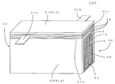
- FIG. 25 is an exploded perspective view schematically showing an expanded state of the heater main body shown in FIG.
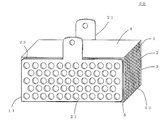
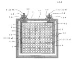
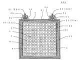
- the heater 100 includes a heater main body 50, a housing 51 for housing the heater main body 50, and a covering material disposed at least a part between the heater main body 50 and the housing 51 and covering at least a part of the heater main body 50. 52, is provided.
- the covering material 52 is made of a material containing at least one of ceramics and glass.
- FIG. 1 is a perspective view schematically showing an embodiment of the heater of the present invention.
- FIG. 2 is a plan view schematically showing one end face of the heater shown in FIG.
- FIG. 3 is a plan view schematically showing the upper surface of the heater shown in FIG.
- FIG. 4 is a cross-sectional view schematically showing a cross section A-A 'in FIG.
- FIG. 5 is a cross-sectional view schematically showing a B-B 'cross section in FIG.
- FIG. 6 is a perspective view schematically showing the heater main body in the heater shown in FIG.
- FIG. 7 is a plan view schematically showing one end face of the heater main body shown in FIG.
- the heater main body 50 has a cylindrical honeycomb structure portion 4 and a pair of electrode portions 21.
- the cylindrical honeycomb structure portion 4 has a partition wall 1 which partitions and forms a plurality of cells 2 extending from one end surface 11 serving as a flow path of the lubricating system fluid to the other end surface 12.
- a pair of electrode portions 21 is disposed on the side surface 5 of the honeycomb structure portion 4.
- the partition walls 1 of the honeycomb structure portion 4 are made of a material containing ceramics as a main component.
- the partition wall 1 generates heat by energization. That is, in the heater 100 of the present embodiment, the partition walls 1 of the honeycomb structure portion 4 serve as a heating element for heating the lubricating system fluid.
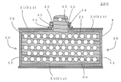
- the housing 51 of the heater 100 of the present embodiment houses the heater main body 50 so as to cover the side surface side of the heater main body 50.
- the housing 51 has an inlet 55 through which the lubricating system fluid flows, and an outlet 56 through which the lubricating system fluid that has passed through the cell 2 formed in the heater body 50 flows out.
- the housing 51 of the heater 100 according to the present embodiment includes a housing main body 51a having an opening on one surface, and a lid 51b for closing the opening of the housing main body 51a.
- the heater main body 50 is disposed inside the housing main body 51a, and then the lid 51b is disposed on the housing main body 51a, whereby the heater main body 50 is accommodated in the housing 51.
- the temperature of the lubricating system fluid can be rapidly raised without excessively heating the lubricating system fluid. Further, even if the size of the heater 100 is small, the temperature of the lubricating system fluid can be raised promptly. That is, as described above, in the heater 100 of the present embodiment, the partition wall 1 itself generates heat due to energization. For this reason, in the process in which the lubricating system fluid circulates in the cell 2, the partition system 1 can continue heating the lubricating system fluid.
- the honeycomb structure part 4 is a honeycomb structure which has the partition 1 which carries out division formation of the some cell 2, a contact area with lubricating system fluid can be enlarged.
- circulates the inside of cell 2 can be heated favorably, and the temperature of a lubricating system fluid can be raised promptly. That is, in the heater 100 of the present embodiment, the lubricating system fluid that has flowed into the heater is subdivided, and the subdivided lubricating system fluid flows in each cell 2.
- the contact area between the lubricating system fluid and the partition wall 1 is increased.
- the amount of heat transfer due to the contact between the partition wall 1 and the lubricating system fluid also increases. Furthermore, when the amount of heat transfer between the partition wall 1 and the lubricating system fluid increases, the amount of heat transfer becomes larger than the amount of heat dissipated by the thermal diffusion in the lubricating system fluid. For this reason, the temperature of the lubricating system fluid tends to rise more quickly.
- the temperature of the lubricating fluid can be reliably increased. This is because the heater 100 of the present embodiment can continue heating the lubricating system fluid in the flow path formed by the cells 2. If the calorific value per unit area of the partition wall 1 is reduced, excessive heating of the lubricating system fluid can be prevented. Therefore, in the heater 100 of the present embodiment, the temperature of the lubricating system fluid can be rapidly raised without excessively heating the lubricating system fluid. Further, since the lubricating system fluid is not excessively heated as described above, the deterioration of the lubricating system fluid can be effectively suppressed.
- the covering material 52 is disposed at least in part between the heater main body 50 and the housing 51.
- the covering material 52 is made of a material containing at least one of ceramics and glass. Therefore, electrical insulation between the heater main body 50 and the housing 51 can be obtained.
- the covering material 52 also functions as a seal layer between the heater main body 50 and the housing 51. Thereby, the sealing performance between the heater main body 50 and the housing 51 can be improved.
- the covering material 52 also functions as a heat insulating layer of the heater main body 50. Thereby, the heat insulation of heater 100 can be improved.
- by disposing the covering material 52 it is possible to suppress heat radiation to the outside of the housing 51 when the heater main body 50 generates heat.
- lubricant system fluid means a generic term for fluids used to lubricate mechanical components.
- examples of the fluid used to lubricate mechanical parts include engine oil, transmission fluid, gear oil, differential oil, brake fluid, power steering fluid and the like.
- the heater of the present embodiment can be used, for example, as a heater for heating a lubricating system fluid such as an engine oil or transmission fluid of an automobile.
- a lubricating system fluid such as an engine oil or transmission fluid of an automobile.
- the above-mentioned lubricating system fluid tends to be low temperature.
- the lubricating system fluid is in a low temperature state, its viscosity becomes high.
- the time to operate while the friction occurring in parts is large increases. Operating the engine or transmission in such a state causes deterioration of fuel efficiency.
- the temperature of engine oil and transmission fluid can be raised promptly. This can reduce the time during which the engine oil and transmission fluid are at a low temperature. As a result, the fuel consumption of the vehicle can be improved.
- transmission fluid contributes more to fuel efficiency deterioration than engine oil.
- large heaters had to be used to fully heat the transmission fluid.
- the transmission fluid can be sufficiently heated. This can further improve the fuel efficiency of the vehicle.
- the heater of this embodiment fully exhibits the effect, when the space for installing a heater like an automobile is limited.
- the heater main body has a cylindrical honeycomb structure portion 4 and a pair of electrode portions 21.
- the cylindrical honeycomb structure part 4 has the partition wall 1 which partitions and forms the some cell 2 extended from one end surface 11 used as the flow path of lubricating system fluid to the other end surface 12.
- the pair of electrode portions 21 is disposed on the side surface 5 of the honeycomb structure portion 4.
- the honeycomb structure portion 4 may further include the outer peripheral wall 3 disposed at the outermost periphery so as to surround the partition wall 1.
- the example in the case where the honeycomb structure part 4 further has the outer peripheral wall 3 is shown.
- a pair of electrode portions 21 is disposed on the side surface 5 of the honeycomb structure portion 4 configured by the outer peripheral wall 3.
- the partition 1 and the outer peripheral wall 3 may be made of the same material or may be made of different materials.
- the partition wall 1 is made of a material containing ceramics as a main component.
- "having ceramic as a main component” means that the ceramic contains 50% by mass or more. That is, a partition made of a material containing ceramics as a main component means a partition containing 50% by mass or more of ceramics.
- Examples of the “ceramics that generate heat by energization” applicable to the honeycomb structure portion of the present embodiment include SiC, metal-impregnated SiC, metal composite SiC, metal composite Si 3 N 4, and the like.
- the specific resistance of the partition wall is preferably 0.01 to 50 ⁇ ⁇ cm. In the heater of this embodiment, the specific resistance of the partition wall is more preferably 0.03 to 10 ⁇ ⁇ cm, and particularly preferably 0.07 to 5 ⁇ ⁇ cm.
- the above-mentioned SiC includes recrystallized SiC and reactive sintered SiC.
- Recrystallized SiC is produced, for example, as follows. First, a raw material containing SiC powder, an organic binder, and "water or organic solvent” is mixed and kneaded to prepare clay. Next, this clay is molded to produce a molded body. Next, the obtained molded product is fired at 1600 to 2300 ° C. in an inert gas atmosphere to obtain a fired product. What is obtained in this manner is "recrystallized SiC". And the obtained sintered body becomes mainly porous. Recrystallized SiC can change the specific resistance by changing the raw material, the particle size, the amount of impurities, and the like. For example, the specific resistance can be changed by solid solution of impurities in SiC. Specifically, by firing in a nitrogen atmosphere, nitrogen can be dissolved in SiC to reduce the specific resistance of recrystallized SiC.
- Reaction-sintered SiC is SiC generated using a reaction between raw materials.
- reaction-sintered SiC porous reaction-sintered SiC and dense reaction-sintered SiC can be mentioned.
- the porous reaction sintered SiC is produced, for example, as follows. First, silicon nitride powder, carbonaceous material, silicon carbide and graphite powder are mixed and kneaded to prepare clay.
- the carbonaceous substance is a substance that reduces silicon nitride. Examples of the carbonaceous substance include solid carbon powder such as carbon black and acetylene black, and resins such as phenol, furan and polyimide. Next, this clay is molded to produce a molded body.
- the above-mentioned compact is subjected to primary firing to obtain a primary fired body.
- the remaining primary graphite is removed by heating and decarburizing the obtained primary fired body in an oxidizing atmosphere.
- the “decarburized primary fired body” is subjected to secondary firing at 1600 to 2500 ° C. to obtain a secondary fired body. What is obtained in this manner is "porous reaction sintered SiC".
- the dense reaction sintered SiC is produced, for example, as follows. First, SiC powder and graphite powder are mixed and kneaded to prepare clay. Next, this clay is molded to produce a molded body. Next, this molded body is impregnated with “molten silicon (Si)”. Thereby, carbon constituting the graphite is reacted with the impregnated silicon to generate SiC. As described above, the pores are easily eliminated by "impregnating" the "molten silicon (Si)" into the molded body. That is, the pores are easily clogged. Therefore, a precise compact can be obtained. What is obtained in this manner is "dense reaction sintered SiC".
- Examples of the “metal-impregnated SiC” described above include Si-impregnated SiC, SiC in which metal Si and other types of metals are impregnated, and the like.
- the partition is made of the above-described material having “metal-impregnated SiC” as a main component, the partition is excellent in heat resistance, thermal shock resistance, oxidation resistance, and corrosion resistance.
- “Corrosion resistance” means the resistance to the corrosion caused by acids and alkalis.
- metal-impregnated SiC for example, one obtained by impregnating a molten metal in a porous body mainly composed of SiC particles can be mentioned. For this reason, metal-impregnated SiC becomes a dense body with relatively few pores.
- Si-impregnated SiC is a concept that collectively refers to a sintered body containing metallic Si and SiC as constituent components.
- Metal Si means metallic silicon.
- Si-impregnated SiC a solid of metallic Si surrounds the surface of the SiC particles.
- the Si-impregnated SiC has a structure in which a plurality of SiC particles are bonded to each other via metal Si.
- SiC impregnated with metal Si and another type of metal is a general term for a sintered body including metal Si, another type of metal and SiC as constituent components.
- SiC impregnated with metal Si and other types of metals the surface of the SiC particles is surrounded by a solid of metallic Si and a solid of other types of metals.
- SiC impregnated with metal Si and another type of metal has a structure in which a plurality of SiC particles are bonded to each other through metal Si or another type of metal.
- the specific resistance of the partition can be adjusted by adjusting the amount of metal to be impregnated.
- the specific resistance of the partition generally decreases as the amount of metal to be impregnated increases.
- metal composite SiC examples include Si composite SiC, SiC obtained by composite sintering of metal Si and other types of metals, and the like.
- other types of metal Al, Ni, Cu, Ag, Be, Mg, Ti etc. can be mentioned, for example.
- metal composite SiC As metal composite SiC, what mixed-sintered SiC particle and metal powder can be mentioned. When mixing and sintering the SiC particles and the metal powder, sintering proceeds at a contact point where the SiC particles and the metal powder are in contact. For this reason, metal composite SiC becomes a porous body in which relatively many pores are formed. In the metal composite SiC, pores of a porous body are formed while taking a structure in which SiC particles are interconnected via a metal phase composed of metal powder. For example, in the case of Si composite SiC, a structure in which SiC particles are bonded to each other via metal Si is taken while forming pores in a form in which a metal Si phase is bonded to the surface of SiC particles. The same structure as that of the above-mentioned metal composite SiC is taken also in SiC in which the metal Si and other types of metals are composite-sintered.
- the specific resistance of the partition can be adjusted by adjusting the amount and component of the metal to be combined.
- the partition is made of a material having metal composite SiC as a main component, generally, as the amount of metal to be combined increases, the specific resistance of the partition decreases.
- the calorific value per unit surface area of the partition depends on the size of the honeycomb structure, the specific resistance of the partition, the thickness of the partition, the cell density and the like.
- the calorific value per unit surface area of the partition can be adjusted by adjusting the thickness of the partition and the cell density. This makes it possible to provide a heater that does not excessively heat the lubricating system fluid.
- the amount of heat generated by the heater can be adjusted by adjusting the size of the honeycomb structure.
- the size of the honeycomb structure portion means the length in the cell extending direction of the honeycomb structure portion and the size of the cross section orthogonal to the cell extending direction of the honeycomb structure portion.
- the length in the cell extending direction of the honeycomb structure portion may be simply referred to as “the length of the honeycomb structure portion”.
- the size of the cross section orthogonal to the extending direction of the cells of the honeycomb structure may be simply referred to as "the size of the cross section of the honeycomb structure”.
- the distance for heating the lubricating system fluid can be increased.
- the lubricating system fluid can be heated satisfactorily.
- the specific resistance of the partition walls may be relatively reduced.
- the resistivity of the partition can be adjusted by adjusting the porosity of the partition.
- the porosity of the partition the lower the specific resistance of the partition.
- the preferable range of the porosity of a partition changes with main components of a partition.
- the porosity of the partition walls is preferably 30 to 90%.
- metal composite SiC is made into the main component, many open pores exist in a partition, and a pore becomes large.
- the partition which has metal complex SiC as a main component many communicating pores which connect between adjacent cells exist. Therefore, the communication pores allow the lubricating system fluid to pass through the inside of the partition wall. Therefore, the contact area between the partition wall and the lubricating system fluid is increased.
- the heating efficiency i.e., heat exchange efficiency
- the heating efficiency can be represented by the "conversion efficiency" described later.
- the porosity of the partition walls is preferably 0 to 10%.
- the pores of the partition become smaller and the number of open pores is reduced. Therefore, it is difficult for the lubricating fluid to intrude into the partition walls containing metal-impregnated SiC as the main component. Therefore, the amount of lubricating system fluid that remains in the pores of the partition wall and stops flowing is reduced.
- the specific resistance of the partition can also be adjusted by the type and purity (amount of impurities) of SiC used as a material of the partition.
- Examples of the type of SiC include ⁇ -SiC and ⁇ -SiC.
- the specific resistance of the partition can also be adjusted.
- the specific resistance of the partition also changes depending on the amount of impurities in the metal contained in the material of the partition.
- an alloy can also be used as a metal contained in the material which is a main component.
- the metal can be alloyed at the time of preparation of the honeycomb structure part. By doing this, the specific resistance of the partition can be changed.
- the thickness of the partition wall is preferably 0.1 to 0.51 mm.
- the cell density of the honeycomb structure part is preferably 15 to 280 cells / cm 2 .
- the thickness of the partition wall is 0.25 to 0.51 mm and the cell density is 15 to 62 cells / cm 2 . It is particularly preferable that the thickness of the partition is 0.30 to 0.38 mm and the cell density is 23 to 54 cells / cm 2 .
- the heater body preferably has an insulating layer with a dielectric breakdown strength of 10 to 1000 V / ⁇ m on the surface of the partition walls of the honeycomb structure part.
- the dielectric breakdown strength of the insulating layer is more preferably 100 to 1000 V / ⁇ m.
- the lubricating system fluid may contain metallic wear powder and moisture generated from parts.
- metallic abrasion powder is mostly removed by an oil filter or the like, but some are not removed and remain in the lubricating system fluid. Therefore, by using the heater for a long time, metal abrasion powder remaining without being removed may adhere to the partition wall or may be accumulated and clogged. In such a case, the heater may be shorted.
- an electrical insulation layer having a dielectric breakdown strength of 10 to 1000 V / ⁇ m (hereinafter, also simply referred to as “insulation”) is provided on the surface of the partition walls of the honeycomb structure, the metallic wear powder contained in the lubricating fluid is a partition wall. It is possible to prevent the short circuit of the heater due to adhesion or deposition on the substrate and clogging.
- the insulating layer examples include an oxide film formed by oxidizing a ceramic component contained in the partition wall. Such an oxide film can be formed by high-temperature treatment in an oxidizing atmosphere.
- the insulating layer may be a ceramic coating layer, a SiO 2 glass coating layer, or a coating layer of a mixture of a ceramic and a “SiO 2 glass”.
- the ceramic coating layer examples include those containing an oxide such as Al 2 O 3 , MgO, ZrO 2 , TiO 2 and CeO 2 as a main component, and those containing a nitride as a main component.
- the oxide-based one and the “nitride-based one” the “oxide-based one” has higher stability in the atmosphere.
- “having nitride as a main component” is more excellent in heat conduction.
- the SiO 2 glass coating layer those containing SiO 2 as a main component can be mentioned.
- a coating layer of a mixture of a ceramic and a SiO 2 -based glass one containing, as a main component, a mixture of SiO 2 and “components such as Al 2 O 3 , MgO, ZrO 2 , TiO 2 , CeO 2 ” is cited. be able to.
- the constituent components of the insulating layer can be appropriately selected according to the required value of the withstand voltage.
- a wet method or a dry method can be employed to form the ceramic coating layer, the SiO 2 glass coating layer, and the coating layer of the mixture of the ceramic and the SiO 2 glass, respectively.
- the slurry for forming the insulating layer and the colloid for forming the insulating layer may be a metal source such as Al, Mg, Si, Zr, Ti, Ce or the like, or An oxide containing the oxide can be used.
- the “insulating layer mainly composed of oxide” is an insulating layer mainly composed of Al 2 O 3 , MgO, SiO 2 , ZrO 2 , TiO 2 , CeO 2 or the like.
- the solution for forming an insulating layer can be used Al (OC 3 H 7) 3 , Si (OC 2 H 5) metal alkoxide solution such as 4.
- the sintering temperature in the wet method can be appropriately determined depending on the main component.
- the sintering temperature in the wet method is preferably, for example, 1100 to 1200 ° C. in the case of the insulating layer containing SiO 2 as a main component. In the case of an insulating layer containing Al 2 O 3 as the main component, the temperature is preferably 1300 to 1400 ° C.
- the honeycomb formed body is immersed in either the slurry for forming the insulating layer, the colloid for forming the insulating layer, or the solution for forming the insulating layer, and then the surplus portion is formed. Remove and dry. Thereafter, it is nitrided in a reducing atmosphere containing nitrogen or ammonia. Thus, an insulating layer containing nitride as a main component can be formed.
- the nitride include AlN, Si 3 N 4, and the like which have insulating properties and high thermal conductivity.
- the dry method may include an electrostatic spray method and the like.
- the formation of the insulating layer by the electrostatic spray method can be performed, for example, as follows. First, a voltage is applied to a powder of insulating material (insulating particles) or a “slurry containing insulating particles” to be negatively (or positively) charged. Thereafter, the charged “insulating particles or a slurry containing insulating particles” is sprayed onto the positively (or negatively) charged honeycomb structure. Thus, the insulating layer is formed.
- the film thickness of the insulating layer can be appropriately set in accordance with the desired withstand voltage.
- the film thickness of the insulating layer is large, although the insulation property is increased, the thermal resistance is increased to heat the lubricating fluid. This is because the heat conductivity of the insulating layer tends to be lower than that of the partition wall. Furthermore, the pressure loss of the heater is increased. Therefore, it is preferable that the thickness of the insulating layer be as thin as possible within the range in which the insulation can be ensured.
- the film thickness of the insulating layer is preferably smaller than the film thickness of the partition wall.
- the thickness of the insulating layer is preferably 10 ⁇ m or less, more preferably 5 ⁇ m or less, and particularly preferably 3 ⁇ m or less. It can prevent that the pressure loss of a honeycomb structure part increases, maintaining heat resistance low as the film thickness of an insulating layer is a value mentioned above.
- the film thickness of the insulating layer means the average film thickness of the insulating layer.
- the film thickness of the insulating layer is a value measured by observation with an optical microscope or an electron microscope using a cross-sectional sample.
- the “cross-sectional sample” is a sample obtained by cutting out a part of the heater main body, and is a sample having a cut surface orthogonal to the wall surface of the partition wall.
- the baking temperature is preferably set to 1200 to 1400 ° C.
- the film thickness of the oxide film can also be adjusted by adjusting the baking time. The longer the firing time, the thicker the oxide film.
- an oxide film is formed on the surface of the partition wall by the oxidation of SiC to generate SiO 2 .
- high temperature processing is performed in oxidizing atmospheres, such as air
- an oxide film is formed on the surface of the partition walls by heat treatment at 1200 ° C. to 1400 ° C. in the air, for example. be able to.
- the shape of the honeycomb structure part is not particularly limited.
- the end face may be a cylindrical (cylindrical) cylindrical shape, the end face may be an oval shaped cylindrical, or the end face may be a polygonal cylindrical end.
- a polygon a quadrangle, a pentagon, a hexagon, a heptagon, an octagon etc. can be mentioned.
- FIGS. 1 to 7 show an example in which the shape of the honeycomb structure portion 4 is a cylinder whose end face is a square.
- the shape of the cell 2 in a cross section orthogonal to the extending direction of the cell 2 is preferably a quadrangle, a hexagon, an octagon, or a combination thereof. Moreover, the shape of the cell 2 in the said cross section may be circular.
- An outer peripheral wall is a wall which comprises the side of a honeycomb structure part.
- the outer peripheral wall may be formed together with the partition walls in the process of manufacturing the honeycomb structure.
- the partition wall and the outer peripheral wall may be extruded at one time.
- the outer peripheral wall can be formed by applying a ceramic material to the outer peripheral portion of the partition wall that partitions and forms the cells.
- the outer peripheral wall 3 is preferably made of a material having ceramics as a main component.
- the outer peripheral wall 3 may be made of the same material as the partition 1 or may be made of a material different from that of the partition 1. Examples of the material of the outer peripheral wall include SiC, metal-impregnated SiC, metal composite SiC, metal composite Si 3 N 4 and the like.
- the outer peripheral wall of the honeycomb structure portion is more preferably thick.
- the thick outer peripheral wall means that the outer peripheral wall is thicker than the partition wall.
- the strength of the outer peripheral wall as a structure increases. Therefore, resistance to thermal stress at the time of joining of the electrode portion can be improved. As a result, it is easy to suppress the formation of cracks and the like on the outer peripheral wall.
- the outer peripheral wall is thick, the heat capacity of the outer peripheral wall is increased. Therefore, the temperature rise of the outer peripheral wall at the time of electricity supply can be reduced.
- the outer peripheral wall is easily overheated because the contact area with the lubricating fluid such as the engine oil is small.
- the resin when used in at least a part of the housing of the heater, the local heating of the heater may deteriorate and damage the resin. Therefore, by thickening the outer peripheral wall of the honeycomb structure portion, it is possible to suppress the damage due to the deterioration of the resin.
- the thickness of the outer peripheral wall depends on the porosity of the outer peripheral wall and the like, but is preferably 0.3 to 5 mm, and more preferably 0.5 to 3 mm.
- the outer peripheral wall of the honeycomb structure part be dense.
- the outer peripheral wall is dense, it is possible to prevent the lubricating system fluid from leaking out of the heater main body through the inside of the outer peripheral wall.
- a sealing material may be disposed on the outer periphery of the heater main body to prevent the leakage of the lubricating system fluid into the housing. Since the lubricating system fluid can be prevented from leaking out of the heater as described above if the outer peripheral wall is made dense, the above sealing material becomes unnecessary.
- the conventional heater is generally configured not to leak lubricating system fluid to the outside of the heater main body.
- the housing and the heater are used.
- a lubricating system fluid may be positively flowed between the main body and the main body. That is, the lubricating system fluid may be positively flowed to the outside of the heater body to heat the lubricating system fluid using the outer surface of the outer peripheral wall of the honeycomb structure.
- the “fine outer peripheral wall” is preferably, for example, one densified by impregnating a metal. Also, the “fine outer peripheral wall” may be formed of the dense “Al 2 O 3 , MgO, SiO 2 , Si 3 N 4 , AlN, or BN”, or a composite thereof.
- the honeycomb structure portion having such a “fine outer peripheral wall” includes, for example, “a material forming the partition wall” and “a material forming the outer peripheral wall” different from the “material forming the partition wall” It can be produced by coextrusion.
- the honeycomb structure portion having “the outer peripheral wall densified by being impregnated with metal” is formed by impregnating the dried honeycomb molded body or the fired honeycomb sintered body with a metal.
- a metal to be impregnated Si is preferable. Then, in order to impregnate the dried honeycomb molded body or the fired honeycomb sintered body with metal, the amount of metal to be impregnated (for example, the amount of impregnated Si) is adjusted so that only the outer peripheral wall is impregnated. There is a method of impregnating metal.
- an impregnation inhibitor is coated on the dried honeycomb molded body or both end surfaces of the fired honeycomb sintered body, or a plate-like jig is placed on the both end surfaces.
- the outer peripheral wall can be preferentially impregnated with metal.
- the impregnation inhibitor for example, oxides, particularly Al 2 O 3 and the like can be mentioned.
- the pair of electrode portions 21 is an electrode for energizing the partition walls 1 of the honeycomb structure portion 4.
- One electrode portion 21 and the other electrode portion 21 in the pair of electrode portions 21 are disposed on the side surface 5 of the honeycomb structure portion 4 so as to sandwich the honeycomb structure portion 4 from the side.
- the partition walls 1 are energized, and the honeycomb structure portion 4 generates heat.
- the material of the pair of electrode parts 21 examples include stainless steel, copper, nickel, aluminum, molybdenum, tungsten, rhodium, cobalt, chromium, niobium, tantalum, gold, silver, platinum, palladium, alloys of these metals, and the like. be able to. Further, the pair of electrode portions 21 is formed using a composite material such as Cu / W composite material, Cu / Mo composite material, Ag / W composite material, SiC / Al composite material, C / Cu composite material, etc. It may be. "Cu / W composite” means copper tungsten composite. "Cu / Mo composite” means copper-molybdenum composite. "Ag / W composite” means silver tungsten composite. "SiC / Al composite” means a composite of SiC and aluminum. “C / Cu composite” means a composite of carbon and copper.
- an electrical resistance is low, a thermal expansion coefficient is low, and the thermal expansion coefficient becomes close to the ceramic of a honeycomb structure part. It is desirable that the electrical resistance is low because if the electrical resistance is high, problems may occur due to the heat generation of the electrode portion itself when energized. Further, the reason why the low thermal expansion coefficient is desirable is as follows. If the thermal expansion coefficient of the electrode material is higher than that of the ceramic, the thermal stress generated at the time of bonding of the electrode portion becomes large, which may cause problems due to interfacial peeling or cracking on the ceramic side.
- the material of the electrode portion can be appropriately selected in consideration of a balance such as generation of a crack in the ceramic due to thermal stress, interfacial peeling of the electrode, heat generation of the electrode portion itself, cost and the like.
- a balance such as generation of a crack in the ceramic due to thermal stress, interfacial peeling of the electrode, heat generation of the electrode portion itself, cost and the like.
- aluminum although the electrical resistance is low, the thermal expansion coefficient is high, so that the electrode portion may be easily peeled off by thermal stress.
- the electrical resistance is relatively high, which may cause a problem in the heat generation of the electrode portion itself.
- noble metal materials such as gold, silver, platinum, palladium, and rhodium may have a problem in material cost although their electrical resistance is particularly low.
- the electrode portion formed using the above-described composite material has a thermal expansion coefficient lower than that of other pure metals such as aluminum, and the thermal expansion coefficient thereof constitutes a honeycomb structure portion. Because they are close to ceramics, the effect of reducing thermal stress during thermal cycling can be expected. The same effect can be obtained with materials having a thermal expansion coefficient lower than that of other metals, such as molybdenum and tungsten.
- each of the pair of electrode portions 21 be formed in a strip shape extending in the direction in which the cells 2 of the honeycomb structure portion 4 extend.
- one electrode portion 21 be disposed on the opposite side of the other electrode portion 21 across the center of the honeycomb structure portion 4.
- FIGS. 1 to 7 show an example in which a pair of electrode portions 21 is disposed on two opposing side surfaces 5 of a honeycomb structure portion 4 whose end surface is formed in a rectangular tube shape.
- the shape of the electrode portion be “a smaller area of the bonding portion of the electrode portion than an area of a shape surrounding the outer periphery of the electrode portion”.
- the shape of the electrode portion may be “a rectangular corner portion formed in a curved shape”. The shape of such an electrode portion is a shape in which thermal stress is reduced. Therefore, “after the electrode part and the honeycomb structure part are joined, generation of a crack in the honeycomb structure part or peeling of the electrode part from the honeycomb structure part” is suppressed. Furthermore, even in the use environment where heating and cooling are repeated, it is possible to prevent peeling of the electrode portion from the honeycomb structure portion and generation of cracks in the honeycomb structure portion.
- the shape of the electrode portion 21 is a rectangular shape in which corner portions are formed in a curved shape. Furthermore, in FIG. 4, the shape of the electrode portion 21 is a plate shape in which a plurality of holes are formed.
- the thermal stress of the electrode portion 21 is reduced by setting the shape of the electrode portion 21 as “a shape in which the corner portion is formed in a curved shape in a rectangular shape” and “a plate shape in which a plurality of holes are formed”.
- the shape of the electrode portion 21 is not limited to the above-described shape. For example, it may be a shape that satisfies only one of “a shape in which corner portions are formed in a curved shape in a rectangle” and “a plate shape in which a plurality of holes are formed”.
- the pair of electrode portions 21 may have terminal portions for securing an electrical connection with a power source or the like.
- the “terminal portion” may be formed on a part of the pair of electrode portions 21.
- an electrode part what has "a main part of an electrode part” and "a projection part extended from a main part of an electrode part” can be mentioned.
- the main body of the electrode portion is a portion actually disposed on the side surface of the honeycomb structure portion.
- a part of the pair of electrode portions 21 may penetrate through the housing 51 and extend to the outside of the housing 51. It is preferable that a part of a pair of electrode part 21 extended to the outer side of the housing 51 is the protrusion part mentioned above. With such a configuration, the partition wall 1 of the heater main body 50 housed in the housing 51 can be easily energized.
- a plate-like or film-like electrode part is manufactured separately from the honeycomb structure part, and the manufactured electrode part is It is preferable to bond to two side surfaces of the honeycomb structure part.
- a conductive bonding material is disposed on the side surface of the honeycomb structure part, and the electrode material and the side surface of the honeycomb structure part The method of joining can be mentioned.
- the above-mentioned conductive bonding material is preferably fired at 60 to 200 ° C. to form a conductive bonding portion.
- the honeycomb structure portion 4 and the pair of electrode portions 21 are interposed via the conductive bonding material (the conductive bonding portion 23 after firing). It means to be joined.
- “to sinter” a material to be fired refers to melting a part of the material to be fired by heating, and combining the components of the material to be fired, It is meant that the product is a fired product (for example, a conductive joint).
- the conductive bonding material is fired and becomes a conductive bonding portion which is a fired product, the honeycomb structure portion and the electrode portion are bonded via the conductive bonding portion.
- a conductive paste containing “polyamide resin, aliphatic amine and silver flake” is referred to as a conductive paste A.
- a conductive paste containing “silver compound, silicate solution and water” is referred to as a conductive paste B.
- a conductive paste containing “nickel powder and silicate solution” is referred to as a conductive paste C.
- the nickel powder is preferably contained in an amount of 30 to 60% by mass with respect to the entire conductive paste C.
- a conductive paste containing “aluminum oxide, graphite and silicate solution” is referred to as a conductive paste D.
- the conductive bonding material is preferably one selected from the group consisting of conductive paste A, conductive paste B, conductive paste C, and conductive paste D. Therefore, it is preferable that the conductive bonding portion 23 be one obtained by firing one selected from the group consisting of the conductive paste A, the conductive paste B, the conductive paste C, and the conductive paste D.
- the heater main body of the heater of this embodiment has a good heat generation performance by energization.
- the heater body of the heater according to the present embodiment has a lower bonding temperature than a general solder bonding or the like. That is, the bonding temperature is 200 ° C. or less.
- the heater main body of the heater of the present embodiment can prevent the electrode portion from peeling from the honeycomb structure portion.
- the conductive joint portion joining the pair of electrode portions and the honeycomb structure portion may contain a metal formed by a thermal spraying method, a cold spray method, or a plating method.
- a conductive joint exhibits a function as an "electrode" together with a pair of electrode parts.
- a conductive joint portion is preferable in that it can be directly formed as a layer having a low electric resistance on the surface of the honeycomb structure portion. Thus, a large current can be supplied to the heater body.
- Examples of the material of the conductive joint include the same materials as the materials of the electrode unit described above. It is desirable that the material of the conductive joint has a low electric resistance and a low thermal expansion coefficient, and the thermal expansion coefficient is close to that of the ceramic of the honeycomb structure, as in the case of the electrode part described above. If the electrical resistance is high, problems may occur due to the heat generation of the conductive junction itself when energized. In addition, when the thermal expansion coefficient is higher than that of the ceramic, the interface between the conductive bonding portion and the honeycomb structure may be separated, or a crack may be generated in the honeycomb structure.
- thermal spraying method a plasma spraying method, a high speed flame spraying method (HVOF method), an arc spraying method, a flame spraying method etc. can be mentioned, for example.
- HVOF method high speed flame spraying method
- arc spraying method a flame spraying method etc.
- the following methods can be mentioned as a method of forming the conductive joint by the thermal spraying method.
- two side surfaces (electrode surface) on which the electrode portions are provided are subjected to sandblasting.
- This sandblasting treatment roughens the surface on which the electrode portion is provided, and removes the oxide film layer from the surface on which the electrode portion is provided.
- a protective cover is disposed on the side surface other than the electrode portion disposition surface so as to cover the side surface.
- the heated and melted powdery raw material is sprayed on the surface on which the electrode portion is provided.
- a coating film to be a conductive bonding portion can be formed on the electrode portion disposition surface.
- a powder raw material pure nickel, a nickel alloy, pure aluminum, an aluminum alloy, pure copper, a copper alloy, pure molybdenum, pure tungsten etc.
- the temperature for heating and melting the powder raw material differs depending on the above-described thermal spraying method, and is preferably set appropriately.
- a thermal spraying method it is difficult to fully densify the conductive joint. That is, according to the thermal spraying method, a conductive joint in which a plurality of pores are formed in the conductive joint can be manufactured. In such a conductive joint, since the Young's modulus is lowered by the formation of the pores, the function of alleviating thermal stress is improved.
- the following method can be mentioned as a method of forming a conductive joint by a cold spray method.
- the electrode portion disposition surface is sandblasted, and a protective cover is disposed on the side surface other than the electrode portion disposition surface so as to cover the side surface.
- a gas such as nitrogen gas, argon gas, air, or the like at about 200 to 600 ° C.
- the powder raw material is collided with the electrode portion disposition surface at an ultra high speed.
- the powder raw material is plastically deformed in the solid state by colliding the powder raw material with the electrode portion disposition surface at an ultra high speed.
- a coating film derived from the powder raw material can be formed on the surface on which the electrode portion is provided.
- the carrier gas is set to a temperature lower than the melting point or softening point of the powder material.
- What can be used as a powder raw material in the cold spray method is mainly a soft metal which is easily plastically deformed as compared with the powder raw material which can be used in the thermal spraying method.
- the melting temperature of the powder raw material is lower than that of the thermal spraying method, the cold spray method is less likely to cause thermal deterioration or oxidation of the powder raw material. Therefore, there is an advantage that it is close to the bulk (solid state) material characteristics.
- pure nickel, pure aluminum, pure copper etc. can be mentioned, for example.
- the following method can be mentioned as a method of forming the conductive joint by the plating method.
- the above-mentioned electrode portion disposition surface is sandblasted, and a protective cover is disposed on the side surface other than the above electrode portion disposition surface so as to cover this side surface.
- a plating process is performed on the surface on which the electrode portion is provided.
- a coating film to be a conductive bonding portion can be formed on the surface on which the electrode portion is provided.
- Examples of the plating method include an electroless plating method, an electrolytic plating method, or a method combining these.
- the electroless plating method it tends to be difficult to form a thick conductive joint. Therefore, after the lower layer (that is, the first layer consisting of the conductive junction) is formed by the electroless plating method, the upper layer (that is, the second layer consisting of the conductive junction part) is formed on the lower layer by the electrolytic plating method can do.
- the electroless plating method and the electrolytic plating method in this manner, a thick conductive joint can be formed.
- pure nickel, pure copper, etc. can be mentioned, for example.
- the conductive joint can be formed by combining methods such as a thermal spraying method, a cold spray method, and a plating method.
- a thermal spraying method for example, after the lower layer is formed by electroless plating, the upper layer can be formed by cold spray on the lower layer.
- the conductive junction can be formed thick.
- the operation of disposing the sand blasting treatment and the protective cover may be adopted as appropriate.
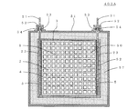
- a heater 300 as shown in FIG. 15 and FIG. 16 can be mentioned.
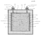
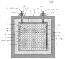
- the configuration of the pair of electrodes 21 of the heater main body 60 is different from the pair of electrode portions described above. That is, as shown in FIG. 17, an electrode substrate 22a disposed on the side of the honeycomb structure 4 and a rod-shaped electrode portion 22b disposed so as to be connected to the electrode substrate 22a, respectively. It consists of The electrode substrate 22a is bonded to the side surface 5 of the honeycomb structure 4 via the conductive bonding portion 23, and a part thereof is along the side surface of the honeycomb structure 4 where the pair of electrode portions 21 is not provided. It is preferable that it is bent. And it is preferable that the bent part of this pair of electrode parts 21 is not in contact with the honeycomb structure part 4.
- the rod-like electrode portion 22b penetrates the housing 51 to form a terminal portion with a power supply or the like. It is preferable to arrange a sealing member such as an O-ring 53 at a portion where the rod-like electrode portion 22 b penetrates the housing 51. With such a configuration, the sealability (pressure resistance) of the portion where the rod-like electrode portion 22 b penetrates the housing 51 can be improved. Further, by providing a rod-like electrode portion having a diameter as shown in FIG. 15 to FIG. 17, there is an effect of suppressing heat generation of the electrode portion itself when a large current flows.
- FIG. 15 is a perspective view schematically showing another embodiment of the heater of the present invention.
- 16 is a cross-sectional view schematically showing a cross section of the heater shown in FIG. 15 which is perpendicular to the flow direction of the lubricating system fluid flowing in the heater main body.
- FIG. 17 is a perspective view schematically showing a heater main body in the heater shown in FIG. In FIG. 15 to FIG. 17, the same reference numerals are assigned to components configured in the same manner as the components shown in FIG. 1 and FIG.
- the housing 51 is a housing that accommodates the heater main body 50 so as to cover the side surface of the heater main body 50.
- the housing 51 has an inlet 55 through which the lubricating system fluid flows, and an outlet 56 through which the lubricating system fluid that has passed through the cell 2 formed in the heater main body 50 flows out.
- the inlet 55 and the outlet 56 are connected to a pipe or the like through which the lubricating fluid flows, so that the lubricating fluid flows into the heater 100.
- the material of the housing is preferably metal or resin.
- the housing can be made excellent in mechanical strength and heat resistance.
- metal materials have the advantage that they can be machined by welding or the like. For this reason, by using a metal material, in general, a housing having excellent reliability when using a heater can be manufactured.
- a resin material which has been commercialized in recent years from the viewpoint of weight reduction of the vehicle, as the housing. By forming the housing from resin, electrical insulation between the heater body and the housing can be obtained.
- a covering material covering at least a part of the heater body is disposed at least at a part between the heater body and the housing. For this reason, electrical insulation between the heater body and the housing is realized by the covering material.
- the covering material As described above, by forming the housing from resin, the insulation between the heater main body and the housing can be made more reliable.
- the resin material generally has a lower thermal conductivity than the metal material, it has a heat insulating effect for confining the heater-heated heat inside the casing.
- the metal forming the housing examples include iron alloys such as stainless steel (SUS), aluminum alloys, magnesium alloys, copper alloys and the like.
- the housing preferably has low heat conduction from the viewpoint of suppressing heat loss when the heater generates heat. Therefore, for example, as a metal forming the housing, stainless steel which is low in thermal conductivity and is a general-purpose material and can be machined can be preferably used. Further, when lightweight is required, an aluminum alloy, a magnesium alloy or the like can be applied.
- a resin which forms a housing it is preferable that it is resin which has heat resistance to such an extent that it does not deform
- EPDM ethylene propylene diene monomer copolymer
- ethylene propylene copolymer polyimide, polyamideimide, silicone, fluoroelastomer, epoxy resin, phenol resin, melamine resin, urea resin, unsaturated polyester resin, alkyd Resin, polyurethane, thermosetting polyimide, polyethylene (PE), polypropylene (PP), polyvinyl chloride (PVC), polyvinylidene chloride, polystyrene (PS), polyvinyl acetate, polytetrafluoroethylene, acrylonitrile butadiene styrene (ABS) Resin, acrylonitrile nitrile (AS) resin, acrylic resin, polyamide, nylon, polyacetal, polycarbonate, modified polyphenylene ether, poly
- EPDM ethylene
- the resin composite material which added glass fiber etc. to each resin mentioned above as resin which forms a housing may be sufficient.
- a resin composite material there is an effect of improving thermal resistance and reducing thermal stress due to low thermal expansion (in other words, improving durability).
- Glass fiber etc. can be used for a reinforced fiber, and when it requires insulation, the fiber which has insulation becomes suitable. From such a thing, when making the output of a heater high, it is preferable to use the resin composite material which raised heat resistance as resin which forms a housing.
- the inlet and the outlet of the housing are the inlet and the outlet of the flow path through which the lubricating system fluid flows in or out.
- the inlet and outlet of the housing may be configured to allow direct connection to the piping through which the lubricating system fluid flows.
- a connection mechanism with the pipe may be further connected to the inlet and the outlet of the housing.
- a pipe joint it is also called a flange joint
- connection mechanism with piping may further include an expanded pipe portion whose diameter gradually increases toward the inflow port, a narrow pipe portion whose diameter gradually decreases from the outflow port, and the like.
- the size of the housing There is no particular limitation on the size of the housing. However, the size needs to be large enough to accommodate the heater body. Further, it is preferable that the size of the housing be such that there is a certain degree of clearance between the housing and the heater body when the heater body is housed.
- the covering material is disposed in the gap.
- a thermal insulator may be further disposed between the housing and the heater body.
- the heat insulating material By arranging the heat insulating material, it is also possible to provide a heat insulating structure in which heat generation of the heater is suppressed from escaping into and from the housing.
- group is suitable also from the heat resistant point at the time of heater heating.
- heat insulating material fiber mats such as ceramic fibers, alumina fibers, silica fibers, glass wool, rock wool and the like, sheets, blankets and the like can be used.
- the “heat insulator” disposed between the housing and the heater main body is, for example, a cotton-like (mat) formed of the above-described fibers and the like so as to leave the internal pores positively in order to make it difficult to conduct heat. Is preferred. Therefore, the thermal conductivity can be greatly reduced as compared with other materials such as metal and resin.
- Such a heat insulating material has almost no sealability to the lubricating system fluid, so it is disposed further outside the covering material covering a part of the heater body.
- the "heat insulating material” used for the heater of this embodiment and the said “coating material” are another component. That is, the “coating material” used for the heater of this embodiment is not contained in the “heat insulating material” here. Furthermore, even if the covering material is not arranged at all the parts of the clearance (that is, when the covering material is arranged only at a part of the clearance), this clearance becomes an air layer and becomes a heat insulation layer of the heater main body. .
- the covering material 52 made of a material containing at least one of ceramic and glass is disposed on the outer peripheral side of the heater main body 50. There may be a gap between it and 51.
- a covering material, a heat insulating material, and a resin material may be arrange
- FIG. 10 is a cross-sectional view schematically showing still another embodiment of the heater of the present invention.
- the cross section shown in FIG. 10 is a cross section perpendicular to the flow direction of the lubricating system fluid flowing in the heater main body.
- elements that are configured the same as the elements shown in FIG. 5 are given the same reference numerals and descriptions thereof will be omitted.
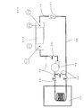
- a covering material made of a material containing at least one of ceramics and glass may be disposed between the heater body and the housing, and a heat insulating material may be disposed outside the material. . That is, as in the heaters 402A and 402B shown in FIGS. 11 and 12, a state in which the covering material 52 and the heat insulating material 57 are laminated between the heater main body 50 (the heater main body 60 in FIG. 12) and the housing 51. It may be arranged at
- the structure and the like inside the housing can be appropriately changed according to the situation and form in which the heater is used.
- a covering material 52 made of a material containing at least one of ceramics and glass needs to be disposed so as to cover a part of the surface of the heater body.
- FIGS. 11 and 12 are cross sectional views schematically showing still another embodiment of the heater of the present invention.
- the cross sections shown in FIGS. 11 and 12 are cross sections perpendicular to the flow direction of the lubricating system fluid flowing in the heater main body.
- FIG. 11 the same reference numerals are given to components configured in the same manner as the components shown in FIG. 5, and the description will be omitted.
- FIG. 12 the same reference numerals are given to components configured in the same manner as the respective components shown in FIG.
- the housing 51 has an electrode extraction portion 54 for extracting the pair of electrode portions 21 of the heater main body 50 housed inside to the outside. ing. Portions on the tip side of the pair of electrode portions 21 from the electrode extraction portion 54 are exposed to the outside, and electrical connection to the pair of electrode portions 21 is enabled.
- an O-ring 53 is disposed at a position where the pair of electrode portions 21 penetrates the housing 51.
- the O-ring 53 secures pressure resistance (sealability) at a portion passing through the housing 51.
- the pressure resistance as used herein means the ability to suppress the leakage of the lubricating fluid to the outside of the housing when the lubricating fluid flows inside the housing. In the heater of this embodiment, the pressure resistance as described above is required so that no problem occurs in the heater operation.
- the lubricating system fluid may be positively flowed to the outside of the heater main body.
- the heater 404 shown in FIG. 13 is a heater configured so that the lubricating system fluid also flows between the heater main body 60 and the housing 51.
- a lubricating system fluid can be heated using the outer surface of the outer peripheral wall 3 of the honeycomb structure part 4.
- FIG. 13 By effectively utilizing the heat generation in the outer peripheral wall 3 in this manner, the heating efficiency of the heater 404 can be improved.
- the lubricating fluid also flows in the cells 2 of the honeycomb structure 4, and the lubricating fluid can be heated also in the cells 2.
- the heater 404 shown in FIG. 13 it is preferable to dispose at least the covering material 52 on the surfaces of the pair of electrode portions 21 of the heater main body 60 to ensure the insulation of the pair of electrode portions 21. That is, the lubricating system fluid may be positively brought into contact with the outer peripheral wall 3 of the honeycomb structure portion 4, but it is preferable that the lubricating system fluid is not in contact with the pair of electrode portions 21.
- the insulation with respect to a pair of electrode parts 21 can be performed by the covering material 52 as mentioned above.
- the housing 51 is made of metal such as SUS, it is preferable to dispose the covering material 52 on the inner surface of the housing 51 to ensure the insulation of the housing 51.
- FIG. 13 is a cross-sectional view schematically showing still another embodiment of the heater of the present invention.
- the cross section shown in FIG. 13 is a cross section perpendicular to the flow direction of the lubricating system fluid flowing in the heater main body.
- the same components as those shown in FIG. 16 are denoted by the same reference numerals and the description thereof will be omitted.
- the housing 73 is made of resin.
- the housing 73 can be formed using an epoxy resin, a fluorine resin, or the like.
- a heat insulating material 57 is filled between the housing 73 and the covering material 52.
- the housing 73 has an electrode extraction portion 74 at a portion where the pair of electrode portions 21 extend from the housing 73.
- an O-ring 53 is disposed at a position where the pair of electrode portions 21 penetrates.
- FIG. 14 is a cross-sectional view schematically showing still another embodiment of the heater of the present invention. The cross section shown in FIG.
- FIG. 14 is a cross section perpendicular to the flow direction of the lubricating system fluid flowing in the heater main body.
- the same components as those shown in FIG. 16 are denoted by the same reference numerals and the description thereof will be omitted.
- the covering is disposed at least in part between the heater body and the housing.
- the covering material used for the heater of this embodiment consists of a material containing at least one of ceramics and glass.
- the covering material is disposed to cover at least a portion of the heater body.
- the covering material functions as an insulating layer, a heat insulating layer, a sealing layer, and the like between the housing and the heater main body in the heater of the present embodiment.
- a coating material is what has electrical insulation.
- the coating material is preferably one that is impermeable to the lubricating system fluid such that the lubricating system fluid does not permeate the coating material.
- the covering material made of a material containing at least one of the ceramic and the glass is made of a dense ceramic or glass which does not allow the lubricating fluid to permeate.
- Ceramics constituting the coating material include SiO 2 , Al 2 O 3 , SiO 2 -Al 2 O 3 , SiO 2 -ZrO 2 , and SiO 2 -Al 2 O 3 -ZrO 2 . Ceramics can be mentioned.
- the glass constituting the coating material e.g., lead-free of B 2 O 3 -Bi 2 O 3 system, B 2 O 3 -ZnO-Bi 2 O 3 system, B 2 O 3 -ZnO system, V 2 O 5 -P 2 O 5 system, SnO-P 2 O 5 system, SnO-ZnO-P 2 O 5 system, SiO 2 -B 2 O 3 -Bi 2 O 3 system, SiO 2 -Bi 2 O 3 -Na 2 O-based glass and the like can be mentioned.
- a covering 52 is preferably disposed between the heater body 50 and the housing 51.
- the covering material 52 is preferably disposed between the heater main body 50 and the housing 51 on the other end face side of the heater main body 50.
- the coating material may be one in which a material containing at least one of ceramics and glass is coated on at least a part of the surface of the heater body.
- the covering material can be formed of a thin film having a thickness of 10 to 500 ⁇ m.
- a gap may be formed between the coating material and the housing.
- a heat insulating material may be further disposed in the gap.
- the gap between the covering material and the housing may be an air layer.
- the lubricating system fluid may flow in the gap between the covering material and the housing.
- the covering material is made of a material containing at least one of ceramic and glass, and therefore, the heat resistance is excellent. Therefore, for example, the heater can be suitably used as a heater having a high output such that the heat generation temperature of the heater body instantaneously becomes 250 ° C. or more, for example, about 300 ° C. to 400 ° C. That is, the heater main body can be used as a heater in a temperature range of normal temperature to about 250 ° C., and can also be used as a heater having a higher heat generation temperature as described above.
- a lubricating system fluid for heating flows inside the heater, and heat is received from the heater body. In other words, the lubricating fluid will draw heat from the heater body.
- the lubricating fluid also acts as a kind of coolant for the heater.
- the heater body generates heat to a high temperature, the actual temperature of the resin material outside the heater body tends to be low. Because of the above, the heater can be used in various applications.
- the covering material 52 is at least disposed between the pair of electrode portions 21 and the housing 51 at a portion where the pair of electrode portions 21 penetrates the housing.
- the O-ring 53 be disposed at a portion passing through the housing 51 from the viewpoint of securing the pressure resistance.
- the covering material is preferably disposed so as to cover at least the entire area of the pair of electrode portions disposed in the heater main body.
- the insulation of the heater main body can be secured.
- the covering material 52 may be disposed between the heater main body 50 and the housing 51 so as to cover the entire side surface side of the heater main body 50.
- FIGS. 8 and 9 are cross-sectional views schematically showing still another embodiment of the heater of the present invention.
- FIG. 8 is a cross section obtained by cutting the heater at the same position as the cross section shown in FIG.
- FIG. 9 is a cross section obtained by cutting the heater at the same position as the cross section shown in FIG.
- the same components as those of the heater shown in FIGS. 1 to 5 are denoted by the same reference numerals and the description thereof will be omitted.
- the covering material 52 As described above, by arranging the covering material 52 so as to cover the entire side surface side of the heater main body 50, the insulation property, the heat insulation property, and the sealing property can be further improved.
- the covering material 52 formed in a predetermined shape is appropriately arranged between the heater main body 50 and the housing 51.
- a material containing at least one of ceramics and glass is a side surface of the heater main body 50. It can be coated and formed.
- a material containing at least one of ceramics and glass is formed by coating a region on the side face of the heater main body where the pair of electrode parts is disposed. be able to.
- a method of forming a covering material by coating the following methods can be mentioned, for example.
- a method for forming a covering material using an inorganic heat resistant adhesive containing ceramics as a main component will be described.
- inorganic heat-resistant adhesives include ceramics such as SiO 2 , Al 2 O 3 , SiO 2 -Al 2 O 3 , SiO 2 -ZrO 2 , and SiO 2 -Al 2 O 3 -ZrO 2.
- the thing which has as a main component can be used.
- Such inorganic heat resistant adhesive is coated on the side of the heater body.
- the coated inorganic heat resistant adhesive is fired at 150 to 300 ° C. in the air.
- a coating material made of ceramics can be formed.
- the covering material may be easily made porous by the above-described firing.
- the coating material treated with the ceramic sealing material is more excellent in sealability.
- the ceramic pore-sealing treatment can be carried out by applying a ceramic pore-sealing material to the surface of a covering material obtained by firing, and then firing at 200 to 350 ° C. in the air.
- the inorganic-type sealing material which has as a main component inorganic materials, such as a silicate system and a silicate sodium system, can be mentioned, for example.
- the method to coat as a covering material can be mentioned as a 2nd covering material preparation method as a covering material. That is, the ceramic sealing material is coated on the side surface of the heater body. Next, the coated ceramic sealing material is fired at 200 to 350 ° C. in the air. In this way, a coating material made of ceramics can be formed. By using the ceramic sealing material, the outer periphery of the heater main body can be coated, and the inside of the pores in the partition of the heater main body near the outer peripheral portion can be sealed.
- the thickness of the covering material obtained by the first and second covering material manufacturing methods described above is, for example, 10 to 500 ⁇ m.
- a method of forming a covering material using low melting point glass will be described. Specifically, a low melting point glass paste is coated on the side of the heater body. As the paste of low melting point glass, those used for bonding and sealing of electronic parts can be used.
- P 2 O 5 system SnO-ZnO-P 2 O 5 system
- SiO 2- B 2 O 3- Bi 2 O 3 system SiO 2- Bi 2 O 3- Na 2 O system, etc.
- the lead-containing system SiO 2 -B 2 O 3 -PbO system and the like can be mentioned, but it is not preferable from the point of containing lead as a component.
- a filler such as eucryptite (Li 2 O-Al 2 O 3 -SiO 2 system) having a lower thermal expansion coefficient is used. It can also be a low melting point glass added. Such low melting point glass paste is coated on the side of the heater body. The coated low melting glass paste is then fired at 400-600 ° C. in air. In this way, a coating material made of low melting glass can be formed.
- a method of forming a covering material using a SiO 2 composite material a method of forming a covering material using a SiO 2 composite material will be described. Specifically, a slurry containing SiO 2 particles is prepared, and a plate-like filler is added to the slurry. As a plate-like filler, mica, glass flakes, talc, kaolin, clay, sericite and the like can be mentioned. The slurry to which the plate-like filler is added is coated on the side of the heater body. The coated slurry is then calcined at 400-600 ° C. in air. In this way, a coating material composed of SiO 2 can be formed.
- a plate-like filler mica, glass flakes, talc, kaolin, clay, sericite and the like can be mentioned.
- the slurry to which the plate-like filler is added is coated on the side of the heater body.
- the coated slurry is then calcined at 400-600 ° C. in
- the thickness of the covering material obtained by the above-mentioned third and fourth covering material manufacturing methods is, for example, 10 to 500 ⁇ m.
- the covering material used for the heater of the present embodiment is made of a material containing at least one of ceramics and glass, and thus is excellent in heat resistance.
- the covering material is preferably usable in a temperature range of 200 ° C. or higher, and more preferably usable in a temperature range of 250 ° C. or higher. It is preferable to select the coating material according to the required heat resistance for each specification of the heater.
- the specific resistance of the covering material is preferably 10 6 ⁇ ⁇ cm or more. Furthermore, the specific resistance of the covering material is preferably 10 8 ⁇ ⁇ cm or more, and particularly preferably 10 10 ⁇ ⁇ cm or more.
- the heater of the present invention provides various vibration absorption structures as follows.
- the heater of the present invention can be mounted around an engine such as a car and used to heat lubricating fluid such as engine oil and transmission fluid. At this time, acceleration is generated by vibration of the engine. For this reason, by setting it as the heater provided with the following vibrational absorption structure, the impact by vibration can be relieved and it can be set as a heater excellent in endurance.
- Examples of the first vibration absorbing structure include a structure in which an electrode portion of the heater main body is provided with an O-ring or packing made of resin, rubber, or the like at a portion penetrating the housing. For example, by making the O-ring 53 shown in FIGS. 4 and 5 into an O-ring 53 made of resin or rubber, a first vibration absorbing structure can be obtained.
- positioned the buffer member to each part of a heater as a 2nd vibrational absorption structure can be mentioned.
- the buffer member include those made of resin and rubber.
- part which the electrode part of a heater main body penetrates a housing, etc. can be mentioned.
- a structure in which a stretchable vibration absorbing portion is provided in a part of the pair of electrode portions of the heater main body can be mentioned.
- a bellows-like part that can be expanded and contracted in a predetermined direction can be mentioned.
- the vibration applied to the heater main body can be favorably absorbed by providing a pair of electrode parts provided with such an expandable and contractible vibration absorbing part.
- FIG. 18 is a cross-sectional view schematically showing still another embodiment of the heater of the present invention.
- the cross section shown in FIG. 18 is a cross section perpendicular to the flow direction of the lubricating system fluid flowing in the heater main body.
- the same components as those shown in FIG. 5 are denoted by the same reference numerals and the description thereof will be omitted.
- a structure employing the following connection method can be mentioned.
- a method of electrical connection to the pair of electrode parts for example, each pair of electrode parts is connected to a cable for electrical connection in the housing, and the cable for electrical connection is drawn to the outside of the housing A method of making an electrical connection can be mentioned.
- a connector insertion port for inserting a connector for electrical connection is formed in a housing that accommodates the heater main body. Then, there is a method of inserting a connector for electrical connection from the connector insertion port of the housing to electrically connect with a pair of electrode portions of the heater main body stored and fixed in the housing.
- the pair of electrode parts is housed in the housing together with the honeycomb structure part. That is, since the pair of electrode portions are not configured to extend through the housing to the outside, vibration applied to the housing is less likely to be transmitted to the heater main body.
- the heater comprised so that a pair of electrode part might extend outside can be mentioned from the inflow side or outflow side of a housing. That is, the heater 100 shown in FIG. 1 is configured such that the pair of electrode portions 21 extend from the side surface of the housing 51 to the outside, but the inlet side or the outlet of the housing of the pair of electrode portions It may be configured to extend outward from the side. As such a heater, for example, a heater 600 shown in FIG. 19 can be mentioned.
- FIG. 19 is a perspective view schematically showing still another embodiment of the heater of the present invention.
- FIG. 20 is a perspective view schematically showing a heater main body in the heater shown in FIG. In FIGS.
- the pair of electrode portions 43 is configured to extend to the outside from the outlet 56 side of the housing 81.
- the lubricating system fluid can be heated to a more uniform temperature.
- the temperature gradient of the lubricating fluid is less likely to occur between the upper and lower portions in the housing, as compared to the configuration in which power is supplied to the pair of electrodes from the upper portion on the side of the housing. It is guessed that.
- each electrode portion 43 of the heater main body 80 extends from the electrode substrate 43a disposed on the side surface 5 of the honeycomb structure 4 to the downstream side in the flow direction of the lubricating fluid from this electrode substrate 43. It has with the electrode terminal part 43b which came out.
- the electrode terminal portion 43b is configured to extend from the outlet 56 (see FIG. 19) side of the housing 81 (see FIG. 19) to the outside.
- FIGS. 21 to 23 a heater 700 as shown in FIGS. 21 to 23 can be mentioned.
- the heater 700 is such that a heater main body 90 as shown in FIGS. 24 and 25 is housed inside a housing 91.
- a covering 52 and a heat insulating material 57 are disposed between the housing 91 and the heater body 90.
- FIG. 21 is a perspective view schematically showing still another embodiment of the heater of the present invention.
- FIG. 22 is a cross-sectional view schematically showing a cross section perpendicular to the flow direction of the lubricating system fluid flowing in the heater main body, of the heater 700 shown in FIG.
- FIG. 23 is a cross-sectional view schematically showing a cross section of the heater 700 shown in FIG.
- FIG. 24 is a perspective view schematically showing a heater main body of the heater 700 shown in FIG.
- FIG. 25 is an exploded perspective view schematically showing an expanded state of the heater main body 90 shown in FIG.
- the housing 91 in the heater 700 includes a housing main body 91a having an opening on one side and a lid 91b for closing the opening of the housing main body 91a. It is constructed. Further, the heater main body 90 has a honeycomb structure portion 4 and a pair of electrode portions 31.
- each electrode portion 31 is configured of an electrode substrate 31a, an electrode terminal portion 31b, and an electrode substrate connecting portion 31c.
- the electrode substrate 31 a is disposed on the side surface 5 of the honeycomb structure unit 4 to apply a voltage to the honeycomb structure unit 4.
- FIGS. 24 and 25 show an example where the electrode substrate 31a is formed in a comb shape.
- the electrode substrate connecting portion 31 c is a portion for connecting the electrode substrate 31 a and the electrode terminal portion 31 b.
- the electrode substrate connecting portions 31c of the pair of electrode portions 31 are sandwiched by the housing main body 91a and the lid portion 91b in a state of being laminated via the electrically insulating sealing material 35. ing.
- the electrode terminal portion 31 b is extended from the electrode substrate connecting portion 31 c sandwiched by the housing main body 91 a and the lid portion 91 b.
- the electrode substrate connecting portion 31c in a stacked state with the sealing material 35 interposed therebetween is held between the housing main body 91a and the lid portion 91b, whereby the electrode portion 31 is taken out of the housing 91.
- the heater 700 of this embodiment is excellent in pressure resistance. That is, with such a configuration, it is possible to effectively prevent the leakage of the lubricating system fluid from the extraction portion of the electrode portion 31 when the lubricating system fluid flows through the inside of the heater 700.
- the heater main body 152 shown in FIG. 27 includes a cylindrical honeycomb structure portion 4 and a pair of electrode portions 24 joined to the side surface 5 of the honeycomb structure portion 4 via the conductive joint portion 23.
- the honeycomb structure portion 4 has a partition wall 1 for partitioning and forming a plurality of cells 2 extending from one end face 11 serving as a flow path of the lubricating system fluid to the other end face 12 and an outer peripheral wall 3 located at the outermost periphery.
- the partition walls 1 are made of a material containing ceramics as a main component, and generate heat when energized.
- the conductive bonding portions 23 are disposed on the two side surfaces 5 of the honeycomb structure portion 4. Through the conductive bonding portion 23, an electrode portion 24 having a corner portion formed in a curved shape is bonded.
- the conductive joint portion 23 preferably includes a metal formed by a thermal spraying method, a cold spray method, or a plating method. Also in such a heater main body 152, as in the heater main body 50 shown in FIG. 6, by being housed in the housing, the heater of the present embodiment can be obtained.
- the heater provided with the heater main body 153 shown in FIG. 28 can be mentioned as other embodiment of the heater of this invention.
- the heater main body 153 shown in FIG. 28 includes a cylindrical honeycomb structure portion 4 and a pair of electrode portions 25 joined to the side surface 5 of the honeycomb structure portion 4 via the conductive joint portion 23.
- the electrode portion 25 includes an electrode substrate 26 a and a rod-like electrode portion 26 b disposed to be connected to the electrode substrate 26 a.
- the heater of the present embodiment can be obtained by being housed in the housing.
- a wire from an external power source or the like is preferably connected to the rod-like electrode portion 26b.
- FIGS. 27 and 28 are perspective views schematically showing a heater main body used in still another embodiment of the heater of the present invention.
- the same reference numerals are assigned to components configured in the same manner as the components shown in FIG. 6 and FIG.
- SiC powder, metal Si powder, water, organic binder and the like are mixed and kneaded to prepare clay. Then, the clay is formed into a honeycomb shape to manufacture a honeycomb formed body. Thereafter, the obtained honeycomb molded body is fired in an inert gas atmosphere to produce a honeycomb structure portion containing Si composite SiC as a main component.
- SiC powder, water, an organic binder or the like may be mixed and kneaded to prepare clay. That is, the raw material of the clay may not contain metal Si powder.
- the material constituting the partition walls and the outer peripheral wall silicon carbide, Fe-16Cr-8Al, SrTiO 3 (perovslite), Fe 2 O 3 (corundum), SnO 3 (rutile), and ZnO (wurzite) etc. It can be mentioned.
- the specific resistance of the partition wall and the outer peripheral wall can be made 0.01 to 50 ⁇ ⁇ cm.
- the specific resistance of silicon carbide is generally wide and 1 to 1000 ⁇ ⁇ cm, and in the case of SiC alone, it is preferable to set it within the aforementioned specific resistance range.
- the value of content of metal Si / (content of Si + content of SiC) is 5 to 50. More preferably, the value of the content of metal Si / (content of Si + content of SiC) is 10 to 40.
- an oxide film may be formed on the surface of the partition wall by high temperature treatment in the atmosphere at 1200 ° C. for 6 hours.
- a pair of electrode parts disposed on the side surface of the honeycomb structure part is formed.
- the material of the electrode portion include stainless steel, copper, nickel, aluminum, molybdenum, tungsten, rhodium, cobalt, chromium, niobium, tantalum, gold, silver, platinum, palladium, alloys of these metals, and the like.
- the material of the electrode portion can be appropriately selected in consideration of a balance such as generation of a crack in the ceramic due to thermal stress, interfacial peeling of the electrode, heat generation of the electrode portion itself, cost and the like.
- the electrode portion has a low thermal expansion coefficient, and the thermal expansion coefficient is close to that of the ceramic of the honeycomb structure portion, which is effective in reducing thermal stress during thermal cycling.
- Molybdenum, tungsten, Cu / W composite You may form using composite materials, such as a material, Cu / Mo composite material, Ag / W composite material, SiC / Al composite material, and C / Cu composite material.
- the formed electrode portion is attached to the side surface of the honeycomb structure portion.
- the heater main body used for the heater of this embodiment is produced.
- a covering material is formed to cover at least a part of the heater body.
- the coating material can be formed according to the above-described first to fourth coating material production methods.
- the housing used for the heater of this embodiment is formed.
- the housing which is a housing having a size capable of housing the heater main body, is manufactured by a conventionally known method.
- methods such as press molding in hot and cold, forging, extrusion, welding, can be mentioned, for example.
- a housing that is a housing having a size capable of housing the heater main body is manufactured.
- Examples of a method of producing a resin-made housing include methods such as resin molding, injection molding, extrusion molding, hollow molding, thermoforming, compression molding and the like.
- a housing can also be produced by shaping
- the covering material it is preferable that the covering material not be in direct contact with the housing.
- a heat insulating material is further disposed on the outside of the covering to cover the heat insulating material
- the housing is made as such.
- the heater main body in which the covering material is formed to cover at least a part of the side is provided in the housing.
- the heater of this embodiment can be manufactured.
- positioning a heat insulating material etc. between a coating material and a housing after accommodating a heater main body in a housing, a heat insulating material etc. are arrange
- a covering material made of a material containing at least one of ceramics and glass may be separately prepared.
- a coating material, a heat insulating material, and the like are appropriately disposed between the heater main body and the housing to manufacture the heater of the present embodiment.
- the honeycomb structure portion 4 is manufactured by the method described above.
- the electrode portion 21 is joined to two of the side surfaces 5 of the honeycomb structure portion 4 arranged in parallel.
- the electrode portion 21 can be formed of Ni, Cu, Mo, W, Cu / W composite material or the like. Thereby, the heater main body 50 in which the pair of electrode parts 21 are formed on the two side surfaces 5 of the honeycomb structure part 4 can be manufactured.
- the covering material 52 is formed on the outer peripheral portion of the obtained heater main body 50 according to the above-described first to fourth covering material manufacturing methods.
- the heat insulating material 57 is further disposed so as to further cover the covering material 52 formed on the side surface 5 of the honeycomb structure portion 4.
- a ceramic fiber sheet Al 2 O 3 -SiO 2 or the like
- a resin sheet may be further disposed so as to further cover the heat insulating material 57.
- a sheet made of silicone resin, fluorine resin or the like can be used as the resin sheet.
- the heater main body 50 in which the covering material 52 is formed in the outer peripheral part and the heat insulating material 57 is further disposed outside thereof is disposed in the housing body made of SUS. Thereafter, a cover made of SUS is disposed on the housing main body such that a part of the pair of electrode parts 21 is exposed.
- the housing main body and the lid are joined, for example, by laser welding or the like, and the heater main body 50 is housed in the housing 51.
- the heater 402A as shown in FIG. 11 can be manufactured.
- the resin housing 73 is formed by a method such as resin molding, injection molding, extrusion molding, hollow molding, thermoforming, compression molding, etc. Make. Then, the heater main body 60, in which the covering material 52 is formed on the outer peripheral portion and the heat insulating material 57 is disposed on the outer side, is disposed in the resin housing 73 to manufacture the heater 405. Even when the resin housing 73 is used, the method of manufacturing the heater main body 60 and the covering material 52 is the same as the manufacturing method described above.
- Example 1 First, a honeycomb structure having Si composite SiC as a main component was produced. Specifically, SiC powder, metal Si powder, water and an organic binder were mixed and kneaded to prepare clay. Next, the clay was formed into a honeycomb shape to prepare a honeycomb formed body. Next, the obtained honeycomb molded body was fired in an inert gas atmosphere to produce a honeycomb structure portion containing Si composite SiC as a main component. The porosity of the obtained Si composite SiC honeycomb was 40%.
- the shape of the honeycomb structure portion was a cylindrical shape having a square end surface.
- the length of each side of the square of the end face was 38 mm.
- the length in the cell extending direction of the honeycomb structure part was 50 mm.
- the thickness of the partition was 0.38 mm.
- the thickness of the outer peripheral wall was 0.38 mm.
- the cell density of the honeycomb structure part was 47 cells / cm 2 .
- the specific resistance of the partition wall and the outer peripheral wall was 30 ⁇ ⁇ cm.
- the honeycomb structure portion was oxidized in the atmosphere to form an insulating oxide film on the surfaces of the partition walls and the outer peripheral wall.
- the surface of each of a pair of opposing surfaces among the four surfaces of the outer peripheral wall of the honeycomb structure portion is subjected to surface processing to remove the oxide film, and then the electrode portion is disposed to manufacture the heater main body.
- the electrode portion is bonded to the outer peripheral wall of the honeycomb structure portion by firing in the air using a conductive paste containing a nickel powder and a silicate solution which is a conductive bonding material. did.
- each electrode part what has a main part of an electrode part actually arranged on the side of a honeycomb structure part, and a projected part which extends from a main part of the electrode part was used.
- the main body of the electrode portion has a surface of the same size as the side surface of the honeycomb structure portion to be disposed.
- the protruding portion of the electrode portion serves as a terminal portion for securing electrical connection with the power supply.
- the material of the electrode portion was pure metallic nickel (Ni).
- the electrode part used what carried out the surface roughening process by sandblasting. As a result, a heater main body in which a pair of electrode portions were disposed on two side surfaces of the honeycomb structure portion was manufactured.
- the outer peripheral portion of the obtained heater main body 50 was coated with an inorganic heat resistant adhesive containing ceramics as a main component.
- the inorganic heat resistant adhesive one having SiO 2 -Al 2 O 3 as a main component was used.
- the method of coating is as follows. First, the inorganic heat resistant adhesive before coating was homogenized by remixing using a ball mill at less than 100 rpm. Then, the inorganic heat resistant adhesive was coated by applying the homogenized heat resistant adhesive by brush coating. The coated inorganic heat resistant adhesive was heated at 80 ° C. in the air as a preheating to suppress the formation of cracks, and then fired at 150 ° C. to prepare a coating material made of a ceramic.
- the obtained coating material was treated with a ceramic pore-sealing material to densify the coating material.
- the thickness of the covering material 52 was 0.4 mm.
- the method of coating the inorganic heat-resistant adhesive in this way to produce a coating material is referred to as “A-type”.
- A-type The method of coating the inorganic heat-resistant adhesive in this way to produce a coating material.
- the housing 51 is constituted by a housing main body 51 a for housing the heater main body 50 and a cover 51 b serving as a cover of the housing main body 51 a.
- the housing 51 is a housing having a size having a gap of about 0.5 to 1 mm between the heater main body 50 coated with the covering material and the housing 51 when the heater main body 50 is housed in the housing 51. .
- the housing 51 is formed with an inlet through which the lubricating system fluid flows, and an outlet through which the lubricating system fluid flows out.
- the material of the housing 51 was stainless steel (SUS304), which is a general-purpose material.
- the thickness of the metal material constituting the housing 51 was 1.5 mm.
- As the lid 51b an electrode lead-out portion 54 is provided at a portion where the pair of electrode portions 21 penetrates, and an O-ring 53 made of fluorine resin is disposed inside the electrode lead-out portion 54.
- the heater main body 50 in which the covering material 52 is disposed at the outer peripheral portion is disposed in the housing main body 51a made of SUS. Thereafter, a cover 51b made of SUS304, which is the same as the housing main body, is disposed on the housing main body 51a so that a part of the pair of electrode parts 21 is exposed.
- the housing body 51 a and the lid portion 51 b were joined by laser welding, and the heater body 50 was housed in the housing 51. Thus, the heater of Example 1 was produced.
- Table 1 shows the material of the electrode portion, the structure of the electrode portion, the structure of the housing, the material of the partition, the porosity (%) of the partition, and the specific resistance ( ⁇ ⁇ cm) of the partition and the outer peripheral wall.
- the "flat plate type" in the column of "Structure of electrode portion” in Table 1 means the electrode portion 21 as shown in FIG. That is, this means that each electrode portion 21 is formed in a single flat plate shape, and a part of the electrode portion 21 disposed on the side surface 5 of the honeycomb structure 4 is drawn out to the outside of the housing 51. Do.
- the “rod type” in the column of “Structure of electrode portion” in Tables 1 to 3 means an electrode in which the electrode portion 21 is disposed on the side surface of the honeycomb structure portion 4 as shown in FIGS. It means a structure comprising a substrate 22a and a rod-like electrode portion 22b arranged to be connected to the electrode substrate 22a.
- “structure of the housing” in Tables 1 to 3 indicates the structure in the housing of the heater of each embodiment, taking the structures shown in FIG. 5, FIG. 11, FIG. 12, FIG. 13 and FIG. It is a thing. That is, when “the structure of the housing” is FIG. 5, the covering material is disposed so as to cover the outer periphery of the heater main body, and the heater main body in the state covered by the covering material has a gap between the covering material and the housing. In the state of providing, it shows that it is a heater of the structure stored in the housing. In the case where the “structure of the housing” is as shown in FIG. 11 and FIG.
- the coating material is disposed so as to cover the heater main body, and further the heat insulator is disposed so as to cover the coating material.
- the structure of an electrode part is a “plate type.”
- the “structure of the electrode portion” is a “bar type”.
- the structure of a housing is FIG. 13, it shows that it is a heater comprised so that a lubricating system fluid may flow also the outer side of the outer peripheral wall of a honeycomb structure part.
- the structure of a housing is FIG. 14, it shows that a housing is formed by the resin material.
- the electric-heating test was done by the following method using the heater of Example 1 obtained.
- the conversion efficiency (%) of Example 1 obtained from the results of the electric heating test is shown in Table 1.
- the heater 800 of each embodiment is installed in a current heating test device 900 as shown in FIG.
- the electric heating test apparatus 900 is provided with a pipe 95 through which a lubricating system fluid circulates.
- a pump 94 is connected to the pipe 95, and the lubricating system fluid is circulated in the pipe 95 by driving the pump 94.
- a valve 98 and a flow meter 99 are installed in the pipe 95.
- thermocouples T1 and T2 and pressure gauges P1 and P2 are disposed on the inlet side and the outlet side of the heater 800.
- FIG. 26 is an explanatory view for explaining a test method of the conduction heating test in the example.
- the heater 800 is installed in the conduction heating test apparatus 900, and the pump 94 is driven to pass the lubricating system fluid into the heater 800.
- An applied voltage (V) as shown in Table 1 is applied to the heater body of the heater 800 which has passed the lubricating system fluid, and the heater 800 heats the lubricating system fluid.
- V applied voltage
- a lubricating system fluid As a lubricating system fluid, a commercially available engine oil (grade: 0 W-30, “Mobil 1 (trade name)” manufactured by ExxonMobil) was used. Table 1 shows the applied voltage (V), the flow rate of the lubricating system fluid to be passed through the heater (L / min), and the initial temperature (° C.) of the lubricating system fluid.
- the initial temperature of the lubricating system fluid is the temperature of the lubricating system fluid before being heated by the heater.
- the conversion efficiency (%) of the heater subjected to the electric conduction heating test was determined based on the following formula (1).
- the conversion efficiency is a time average value at the time of test.
- the “heat transfer amount to the lubricating system fluid” in the following equation (1) is a value calculated by the following equation (2).
- the “input power amount” in the following equation (1) is a value calculated by the following equation (3).
- the “temperature difference of the lubricating system fluid” in the equation (2) means the “temperature difference of the lubricating system fluid flowing out of the outlet of the housing when the temperature of the lubricating system fluid flowing out of the outlet reaches 60 ° C. The value of the difference between the temperature and the temperature of the lubricating system fluid flowing in from the inlet of the housing.
- Conversion efficiency (%) amount of heat transfer to lubricating system fluid / amount of input power (1)
- Heat transfer amount to lubricating system fluid flow rate of lubricating system fluid ⁇ specific heat ⁇ temperature difference of lubricating system fluid (2)
- Input power amount power (W) ⁇ time (seconds) (3)
- the test was performed by adjusting the value of the applied voltage applied to the heater main body. That is, the applied voltage was set in the range of 100 to 400 V, with the heater main body having a relatively large specific resistance value as the “high resistance product”. In addition, the applied voltage was in the range of 10 to 60 V, with the heater main body having a relatively small specific resistance value as the “low resistance product”.
- Example 2 A heater was produced in the same manner as in Example 1 except that the material of the electrode portion, the structure of the electrode portion, and the structure of the housing were changed as shown in Table 1.
- the electric-heating test was done by the method similar to Example 1 using the obtained heater.
- the conversion efficiency (%) determined from the results of the electric heating test is shown in Table 1.
- Table 1 shows the applied voltage (V), the flow rate of the lubricating system fluid to be passed through the heater (L / min), and the initial temperature (° C.) of the lubricating system fluid in the electric heating test.
- Example 3 in which the “structure of the housing” is as shown in FIG. 11, a ceramic fiber sheet (Al 2 O 3 —SiO 2 system) with a thickness of 5 mm was used as the disconnecting material.
- Example 6 pure metal copper (Cu) was used as the material of the electrode portion.
- the thickness 5mm ceramic fiber sheet (Al 2 O 3 -SiO 2 system) was used.
- Example 7 a heater was produced in the same manner as in Example 3 except that the coating material was produced as follows.
- the ceramic sealing material used in Example 1 was applied as a covering material.
- a material system containing tetraethyl orthosilicate (TEOS: Si (OC 2 H 5 ) 4 ), a silane coupling agent, 2-propanol, 1-butanol and water as main components was used.
- TEOS tetraethyl orthosilicate
- 2-propanol 1-butanol
- water water
- Example 8 a heater was produced in the same manner as in Example 3 except that the coating material was produced as follows. First, a paste of low melting glass was homogenized by remixing with a ball mill at less than 100 rpm before use, and then coated on the outer peripheral portion of the heater body by brush coating. A paste of SnO-P 2 O 5 was used as a paste of low melting point glass. The coated low melting glass paste was fired in air at 150 ° C. as preheating for volatilization of the organic solvent and then at 480 ° C. to prepare a coating of low melting glass. The thickness of the coating was about 0.5 mm. The method of coating the paste of low melting glass to make a coating material is referred to as “C-type”. In the column of “Production Method of Coating Material” in Table 1, the production method of the coating material in Example 8 is shown.
- Example 9 a heater was produced in the same manner as in Example 3 except that the coating material was produced as follows. First, a slurry containing SiO 2 particles was prepared, and a plate-like filler was added to the slurry. Mica was used as the plate-like filler. The slurry to which the plate-like filler was added was coated on the outer peripheral portion of the heater body. The coated slurry was fired at 400-600 ° C. in air to make a vitreous coating. The thickness of the covering material was about 0.4 mm. The method of coating a slurry containing SiO 2 particles to produce a coating material is referred to as “D-type”. In the column of “Production Method of Coating Material” in Table 1, the production method of the coating material in Example 9 is shown.
- the electric heating test was conducted in the same manner as in Example 1 using the obtained heaters of Examples 7-9.
- the conversion efficiency (%) determined from the results of the electric heating test is shown in Table 1.
- Table 1 shows the applied voltage (V), the flow rate of the lubricating system fluid to be passed through the heater (L / min), and the initial temperature (° C.) of the lubricating system fluid in the electric heating test.
- Example 10 to 17 A heater was produced in the same manner as in Example 1 except that the material of the electrode portion, the structure of the electrode portion, the structure of the housing, and the method of producing the covering material were changed as shown in Table 1.
- the structure of the electrode portion is “rod-shaped”.
- the rod-shaped electrode portion is a cylindrical one having a diameter of 6 mm at its end face.
- the heater of Examples 10-17 has a “housing structure” of FIG.
- a ceramic fiber sheet (Al 2 O 3 -SiO 2 -based) having a thickness of 5 mm was used as a disconnecting material.
- Example 1 The electric heating test was conducted in the same manner as in Example 1 using the heaters of Examples 10 to 17.
- the conversion efficiency (%) determined from the results of the electric heating test is shown in Table 1.
- Table 1 shows the applied voltage (V), the flow rate of the lubricating system fluid to be passed through the heater (L / min), and the initial temperature (° C.) of the lubricating system fluid in the electric heating test.
- Example 18 to 31 A heater was produced in the same manner as in Example 1 except that the material of the electrode portion, the structure of the electrode portion, the structure of the housing, the method of producing the covering material, and the material of the partition wall were changed as shown in Table 2.
- a ceramic fiber sheet Al 2 O 3 -SiO 2 -based having a thickness of 5 mm was used as the disconnecting material.
- the electric heating test was conducted in the same manner as in Example 1 using the heaters of Examples 18 to 31 thus obtained.
- the conversion efficiency (%) obtained from the results of the electric heating test is shown in Table 2.
- Table 2 shows the applied voltage (V), the flow rate of the lubricating system fluid to be passed through the heater (L / min), and the initial temperature (° C.) of the lubricating system fluid in the electric heating test.
- the material of the partition walls was “recrystallized SiC”.
- the manufacturing method of the honeycomb structure part which has a partition which consists of recrystallized SiC is as follows. First, raw materials containing SiC powder, an organic binder, and "water or organic solvent” were mixed and kneaded to prepare clay. Next, this clay was molded to produce a honeycomb molded body. Next, the obtained molded body was fired at a predetermined temperature (1600 to 2300 ° C.) in a nitrogen gas atmosphere to produce a honeycomb structure part.
- the material of the partition wall was “Si-impregnated SiC”.
- the manufacturing method of the honeycomb structure part which has a partition which consists of Si impregnation SiC is as follows. Specifically, SiC powder, an organic binder, and water were mixed and kneaded to prepare a clay. Next, a molded body was produced so that the clay was formed into a predetermined honeycomb shape shown in Table 2. Next, a mass of metal Si was placed on the obtained formed body, and the formed body was impregnated with Si in a reduced pressure argon (Ar) gas atmosphere. Thus, a honeycomb structure portion containing Si-impregnated SiC as a main component was produced.
- the material of the partition walls was “reactive sintered SiC (porous)”.
- “Reaction-sintered SiC (porous)” refers to porous reaction-sintered SiC.
- the manufacturing method of the honeycomb structure part which has a partition which consists of reaction sintering SiC (porous) is as follows. First, silicon nitride powder, carbonaceous material, silicon carbide and graphite powder are mixed and kneaded to prepare clay. Next, this clay was molded to produce a honeycomb molded body. Next, the above molded body was subjected to primary firing in a non-oxidative atmosphere to obtain a primary fired body.
- the remaining primary graphite was removed by heating and decarburizing the obtained primary fired body in an oxidizing atmosphere.
- the “decarburized primary fired body” was subjected to secondary firing at a predetermined temperature (1600 to 2500 ° C.) in a non-oxidizing atmosphere to obtain a secondary fired body.
- the obtained secondary fired body is a honeycomb structure part.
- the material of the partition walls was “reactive sintered SiC (dense)”.
- “Reaction-sintered SiC (dense)” means dense reaction-sintered SiC.
- the manufacturing method of the honeycomb structure part which has a partition which consists of reaction sintering SiC (dense substance) is as follows. First, SiC powder and graphite powder were mixed and kneaded to prepare clay. Next, this clay is formed to produce a honeycomb formed body. Next, this molded body was impregnated with “molten silicon (Si)”. As a result, carbon constituting the graphite is reacted with the impregnated silicon to form SiC. The structure obtained in this manner is a honeycomb structure part.
- Examples 32 to 45 A heater was manufactured in the same manner as in Example 1 except that the material of the electrode portion, the structure of the electrode portion, the structure of the housing, the method of preparing the covering material, and the material of the partition wall were changed as shown in Table 3.
- ceramic fiber sheets Al 2 O 3 -SiO 2 -based having a thickness of 5 mm were used as the disconnecting material.
- Example 3 The electric heating test was conducted in the same manner as in Example 1 using the heaters of Examples 32 to 45 thus obtained.
- the conversion efficiency (%) obtained from the result of the electric heating test is shown in Table 3.
- Table 3 shows the applied voltage (V), the flow rate of the lubricating system fluid to be passed through the heater (L / min), and the initial temperature (° C.) of the lubricating system fluid in the conduction heating test.
- Examples 40 and 41 pure metal molybdenum was used as the material of the electrode portion. In the column of “Material of power section” in Table 3, molybdenum is described as “Mo”. In Examples 42 and 43, pure metal tungsten was used as the material of the electrode portion. Tungsten is described as “W” in the column of “Material of power portion” in Table 3. In Examples 44 and 45, a copper-tungsten composite material was used as the material of the electrode portion. In addition, this composite material used that whose volume ratio of tungsten (W) is 85%. In the column of “Material of power section” in Table 3, the copper-tungsten composite material is described as “Cu / W”.
- Example 46 The material of the electrode portion, the structure of the electrode portion, the structure of the housing, and the material of the partition wall are changed as shown in Table 3, and the heater is formed of resin (that is, the “housing structure” is the heater of FIG. 14)
- the heater is formed of resin (that is, the “housing structure” is the heater of FIG. 14)
- a heater main body having a honeycomb structure part corresponding to the material of the partition shown in Table 3 was produced.
- a coating material was coated on the outer peripheral portion of the heater body in the same manner as in Example 1 to form a coating material.
- a housing was manufactured using a fluorine-based resin.
- the heater main body in which the covering material was formed was stored in the obtained resin-made housing, and also the heat insulation material of the ceramic fiber sheet was arrange
- the electric-heating test was done by the method similar to Example 1 using the obtained heater.
- the conversion efficiency (%) obtained from the result of the electric heating test is shown in Table 3.
- Table 3 shows the applied voltage (V), the flow rate of the lubricating system fluid to be passed through the heater (L / min), and the initial temperature (° C.) of the lubricating system fluid in the conduction heating test.
- Example 50 The material of the electrode portion, the structure of the electrode portion, the structure of the housing, and the material of the partition wall were changed as shown in Table 3, and a heater having a structure as shown in FIG. 12 was produced.
- the low temperature operation was simulated, and the test was performed in a state where the initial temperature of the lubricating system fluid was lowered to 0 ° C.
- the electric-heating test was done by the method similar to Example 1 using the obtained heater.
- the conversion efficiency (%) obtained from the result of the electric heating test is shown in Table 3.
- Table 3 shows the applied voltage (V), the flow rate of the lubricating system fluid to be passed through the heater (L / min), and the initial temperature (° C.) of the lubricating system fluid in the conduction heating test.
- the heater of Example 1 in which the heat insulating material was not disposed inside the housing had a conversion efficiency of 67%. Although the conversion efficiency was low as compared with the heaters of Examples 2-51, it was found that a sufficient heat insulating effect was exhibited by the coating material made of the ceramic as in Example 1. Moreover, this coating material also had good insulation and sealability. Further, as shown in Tables 1 to 3, the conversion efficiency can be further improved by additionally using a heat insulating material of the ceramic fiber sheet in addition to the covering material or making the housing of resin. Moreover, the weight reduction of a heater was also realizable by making a housing into resin.
- the covering material made of ceramic or glass on the side surface of the heater main body makes it possible to reduce the weight and to easily manufacture the housing structure in a low temperature process.
- the resin material may be thermally damaged due to local heat generation in some cases when the output becomes high, but the covering material made of ceramic or glass as in the present invention When they were formed on the side of the heater body, they did not have these problems, and they functioned well as an insulating layer.
- a heater body having a honeycomb-shaped honeycomb structure portion and a pair of electrode portions disposed on the side surface miniaturization, early heating, and high conversion can be performed as compared with a conventional heater. It turned out that an efficiency is obtained.
- the present invention can be used as a heater that can be used to heat lubricating fluid such as engine oil and transmission fluid.
Abstract
Description
本発明のヒーターの一の実施形態は、図1~図5に示すようなヒーター100である。本実施形態のヒーター100は、ヒーター本体50、ヒーター本体50を収納するハウジング51、及びヒーター本体50とハウジング51との間の少なくとも一部に配置され、ヒーター本体50の少なくとも一部を覆う被覆材52、を備えたものである。本実施形態のヒーター100においては、被覆材52が、セラミックス及びガラスの少なくとも一方を含む材料からなる。 (1) Heater:
One embodiment of the heater of the present invention is a
ヒーター本体は、図6及び図7に示すように、筒状のハニカム構造部4、及び一対の電極部21を有するものである。筒状のハニカム構造部4が、潤滑系流体の流路となる一方の端面11から他方の端面12まで延びる複数のセル2を区画形成する隔壁1を有する。このヒーター本体においては、一対の電極部21が、ハニカム構造部4の側面5に配設されている。 (1-1) Heater body:
As shown in FIGS. 6 and 7, the heater main body has a cylindrical
図1~図5に示すように、ハウジング51は、ヒーター本体50の側面側を覆うようにヒーター本体50を収納する、筐体である。ハウジング51は、潤滑系流体が流入する流入口55と、ヒーター本体50に形成されたセル2を通過した潤滑系流体が流出する流出口56と、を有するものである。流入口55と流出口56とが、潤滑系流体が流れる配管等に接続されて、ヒーター100の内部に潤滑系流体が流入するようになる。 (1-2) Housing:
As shown in FIGS. 1 to 5, the
被覆材は、ヒーター本体とハウジングとの間の少なくとも一部に配置されたものである。本実施形態のヒーターに用いられる被覆材は、セラミックス及びガラスの少なくとも一方を含む材料からなるものである。被覆材は、ヒーター本体の少なくとも一部を覆うように配置されている。この被覆材が、本実施形態のヒーターにおける、ハウジングとヒーター本体との絶縁層、断熱層、シール層等として機能する。このため、被覆材は、電気絶縁性を有するものであることが好ましい。また、被覆材は、潤滑系流体が被覆材を透過しないような潤滑系流体不透過性を有するものであることが好ましい。このため、セラミックス及びガラスの少なくとも一方を含む材料からなる被覆材は、潤滑系流体が透過しないような緻密質なセラミックスやガラスからなるものであることがより好ましい。 (1-3) Coating material:
The covering is disposed at least in part between the heater body and the housing. The covering material used for the heater of this embodiment consists of a material containing at least one of ceramics and glass. The covering material is disposed to cover at least a portion of the heater body. The covering material functions as an insulating layer, a heat insulating layer, a sealing layer, and the like between the housing and the heater main body in the heater of the present embodiment. For this reason, it is preferable that a coating material is what has electrical insulation. The coating material is preferably one that is impermeable to the lubricating system fluid such that the lubricating system fluid does not permeate the coating material. For this reason, it is more preferable that the covering material made of a material containing at least one of the ceramic and the glass is made of a dense ceramic or glass which does not allow the lubricating fluid to permeate.
次に、本発明のヒーターの更に他の実施形態について説明する。本発明のヒーターの更に他の実施形態としては、下記のような、各種の振動吸収構造を備えたヒーターを挙げることができる。本発明のヒーターは、自動車等のエンジンの周辺に搭載されて、エンジンオイルやトランスミッションフルードなどの潤滑系流体を加熱するために用いることができる。この際、エンジンの振動により、加速度が発生する。このため、下記のような振動吸収構造を備えたヒーターとすることで、振動による衝撃を緩和して、耐久性に優れたヒーターとすることができる。 (2) Still another embodiment of the heater:
Next, still another embodiment of the heater of the present invention will be described. As other embodiment of the heater of this invention, the heater provided with various vibration absorption structures as follows can be mentioned. The heater of the present invention can be mounted around an engine such as a car and used to heat lubricating fluid such as engine oil and transmission fluid. At this time, acceleration is generated by vibration of the engine. For this reason, by setting it as the heater provided with the following vibrational absorption structure, the impact by vibration can be relieved and it can be set as a heater excellent in endurance.
次に、本実施形態のヒーターを製造する方法について説明する。なお、本実施形態のヒーターを製造する方法については、以下の製造方法に限定されることはない。 (3) Heater manufacturing method:
Next, a method of manufacturing the heater of the present embodiment will be described. In addition, about the method of manufacturing the heater of this embodiment, it is not limited to the following manufacturing methods.
まず、Si複合SiCを主成分とするハニカム構造部を作製した。具体的には、SiC粉体、金属Si粉体、水、有機バインダーを混ぜ合わせ、混練して坏土を調製した。次に、この坏土をハニカム形状に成形して、ハニカム成形体を作製した。次に、得られたハニカム成形体を、不活性ガス雰囲気中において焼成することにより、Si複合SiCを主成分とするハニカム構造部を作製した。得られたSi複合SiCハニカムの気孔率は40%であった。 Example 1
First, a honeycomb structure having Si composite SiC as a main component was produced. Specifically, SiC powder, metal Si powder, water and an organic binder were mixed and kneaded to prepare clay. Next, the clay was formed into a honeycomb shape to prepare a honeycomb formed body. Next, the obtained honeycomb molded body was fired in an inert gas atmosphere to produce a honeycomb structure portion containing Si composite SiC as a main component. The porosity of the obtained Si composite SiC honeycomb was 40%.
まず、図26に示すような通電加熱試験装置900に、各実施例のヒーター800を設置する。通電加熱試験装置900は、潤滑系流体が循環する配管95を備えたものである。この配管95には、ポンプ94が接続されており、ポンプ94を駆動させることにより、配管95内に潤滑系流体が循環する。また、この配管95には、バルブ98及び流量計99が設置されている。また、ヒーター800の流入口側及び流出口側には、熱電対T1,T2及び圧力計P1,P2が配置されている。これにより、ヒーター800のハウジングの流入口から流入する潤滑系流体の温度と圧力、及びヒーター800のハウジングの流出口から流出する潤滑系流体の温度と圧力を測定することができる。クーラー96は潤滑系流体の初期温度を調整するために使われる。図26は、実施例における通電加熱試験の試験方法を説明するための説明図である。 [Electric heating test]
First, the
潤滑系流体への伝熱量=潤滑系流体の流量×比熱×潤滑系流体の温度差 ・・・(2)
投入電力量=電力(W)×時間(秒) ・・・(3) Conversion efficiency (%) = amount of heat transfer to lubricating system fluid / amount of input power (1)
Heat transfer amount to lubricating system fluid = flow rate of lubricating system fluid × specific heat × temperature difference of lubricating system fluid (2)
Input power amount = power (W) × time (seconds) (3)

電極部の材質、電極部の構造、及びハウジングの構造を表1に示すように変更した以外は、実施例1と同様の方法でヒーターを作製した。得られたヒーターを用いて、実施例1と同様の方法で通電加熱試験を行った。通電加熱試験の結果から求められた変換効率(%)を表1に示す。表1に、通電加熱試験における、印加電圧(V)、ヒーター内を通過させる潤滑系流体の流量(L/min)、及び潤滑系流体の初期温度(℃)を示す。 (Examples 2 to 6)
A heater was produced in the same manner as in Example 1 except that the material of the electrode portion, the structure of the electrode portion, and the structure of the housing were changed as shown in Table 1. The electric-heating test was done by the method similar to Example 1 using the obtained heater. The conversion efficiency (%) determined from the results of the electric heating test is shown in Table 1. Table 1 shows the applied voltage (V), the flow rate of the lubricating system fluid to be passed through the heater (L / min), and the initial temperature (° C.) of the lubricating system fluid in the electric heating test.
実施例7においては、以下のように被覆材を作製した以外は、実施例3と同様の方法でヒーターを作製した。ここでは、実施例1で使用したセラミックス封孔材を被覆材として適用した。セラミックス封孔材としては、オルトケイ酸テトラエチル(TEOS:Si(OC2H5)4)、シランカップリング剤、2プロパノール、1ブタノール、及び水を主成分として含有する材料系を使用した。まず、使用前にボールミルを用いて100rpm未満にて再混合することで均質化した後、刷毛塗りでヒーター本体の外周部分にコーティングした。コーティングしたセラミックス封孔材を、大気中で、クラック生成の抑制のため予備加熱として80℃、その後に150℃、更には本焼成として350℃で焼成して、セラミックスからなる被覆材を作製した。被覆材の厚さは、約0.05mmとした。尚、セラミックス封孔材の場合、ハニカムヒーター部の外周をコーティングすると共に、外周部に近いヒーター隔壁中の気孔内部を目封じするものである。セラミックス封孔材を添加した無機系耐熱接着剤をコーティングして被覆材を作製する方法を、「B型」とする。表1における「被覆材の作製方法」の欄に、実施例7における被覆材の作製方法を示す。 (Example 7)
In Example 7, a heater was produced in the same manner as in Example 3 except that the coating material was produced as follows. Here, the ceramic sealing material used in Example 1 was applied as a covering material. As the ceramic sealing material, a material system containing tetraethyl orthosilicate (TEOS: Si (OC 2 H 5 ) 4 ), a silane coupling agent, 2-propanol, 1-butanol and water as main components was used. First, after homogenization by re-mixing using a ball mill at less than 100 rpm before use, the outer peripheral portion of the heater body was coated with a brush. The coated ceramic sealing material was fired in the air at 80 ° C. as preheating for suppression of crack formation, then at 150 ° C., and further at 350 ° C. as main firing to prepare a covering material made of ceramics. The thickness of the coating was about 0.05 mm. In the case of the ceramic sealing material, the outer periphery of the honeycomb heater portion is coated, and the inside of the pores in the heater partition close to the outer peripheral portion is sealed. Let the method of coating the inorganic type heat-resistant adhesive which added the ceramic sealing material, and producing a coating material be "B type." In the column of “Production Method of Coating Material” in Table 1, the production method of the coating material in Example 7 is shown.
実施例8においては、以下のように被覆材を作製した以外は、実施例3と同様の方法でヒーターを作製した。まず、低融点ガラスのペーストを、使用前にボールミルを用いて100rpm未満にて再混合することで均質化した後、刷毛塗りでヒーター本体の外周部分にコーティングした。低融点ガラスのペーストとしては、SnO-P2O5のペーストを用いた。コーティングした低融点ガラスのペーストを、大気中で、有機溶媒の揮発のため予備加熱として150℃、その後に480℃で焼成して、低融点ガラスからなる被覆材を作製した。被覆材の厚さは、約0.5mmとした。低融点ガラスのペーストをコーティングして被覆材を作製する方法を、「C型」とする。表1における「被覆材の作製方法」の欄に、実施例8における被覆材の作製方法を示す。 (Example 8)
In Example 8, a heater was produced in the same manner as in Example 3 except that the coating material was produced as follows. First, a paste of low melting glass was homogenized by remixing with a ball mill at less than 100 rpm before use, and then coated on the outer peripheral portion of the heater body by brush coating. A paste of SnO-P 2 O 5 was used as a paste of low melting point glass. The coated low melting glass paste was fired in air at 150 ° C. as preheating for volatilization of the organic solvent and then at 480 ° C. to prepare a coating of low melting glass. The thickness of the coating was about 0.5 mm. The method of coating the paste of low melting glass to make a coating material is referred to as “C-type”. In the column of “Production Method of Coating Material” in Table 1, the production method of the coating material in Example 8 is shown.
実施例9においては、以下のように被覆材を作製した以外は、実施例3と同様の方法でヒーターを作製した。まず、SiO2粒子を含有したスラリーを用意し、このスラリーに、板状フィラーを添加した。板状フィラーとしては、マイカを用いた。板状フィラーを添加したスラリーを、ヒーター本体の外周部分にコーティングした。コーティングしたスラリーを、大気中で、400~600℃で焼成して、ガラス質の被覆材を作製した。被覆材の厚さは、約0.4mmとした。SiO2粒子を含有したスラリーをコーティングして被覆材を作製する方法を、「D型」とする。表1における「被覆材の作製方法」の欄に、実施例9における被覆材の作製方法を示す。 (Example 9)
In Example 9, a heater was produced in the same manner as in Example 3 except that the coating material was produced as follows. First, a slurry containing SiO 2 particles was prepared, and a plate-like filler was added to the slurry. Mica was used as the plate-like filler. The slurry to which the plate-like filler was added was coated on the outer peripheral portion of the heater body. The coated slurry was fired at 400-600 ° C. in air to make a vitreous coating. The thickness of the covering material was about 0.4 mm. The method of coating a slurry containing SiO 2 particles to produce a coating material is referred to as “D-type”. In the column of “Production Method of Coating Material” in Table 1, the production method of the coating material in Example 9 is shown.
電極部の材質、電極部の構造、ハウジングの構造、及び被覆材の作製方法を表1に示すように変更した以外は、実施例1と同様の方法でヒーターを作製した。実施例10~17においては、電極部の構造が「棒型」である。この棒型の電極部は、端面の直径が6mmの円柱状のものである。実施例10~17のヒーターは、「ハウジングの構造」が図12である。この実施例10~17のヒーターにおいては、断絶材として、厚み5mmのセラミックスファイバーシート(Al2O3-SiO2系)を用いた。 (Examples 10 to 17)
A heater was produced in the same manner as in Example 1 except that the material of the electrode portion, the structure of the electrode portion, the structure of the housing, and the method of producing the covering material were changed as shown in Table 1. In Examples 10 to 17, the structure of the electrode portion is “rod-shaped”. The rod-shaped electrode portion is a cylindrical one having a diameter of 6 mm at its end face. The heater of Examples 10-17 has a “housing structure” of FIG. In the heaters of Examples 10 to 17, a ceramic fiber sheet (Al 2 O 3 -SiO 2 -based) having a thickness of 5 mm was used as a disconnecting material.
電極部の材質、電極部の構造、ハウジングの構造、被覆材の作製方法、及び隔壁の材料を表2に示すように変更した以外は、実施例1と同様の方法でヒーターを作製した。実施例18~31のヒーターにおいては、断絶材として、厚み5mmのセラミックスファイバーシート(Al2O3-SiO2系)を用いた。 (Examples 18 to 31)
A heater was produced in the same manner as in Example 1 except that the material of the electrode portion, the structure of the electrode portion, the structure of the housing, the method of producing the covering material, and the material of the partition wall were changed as shown in Table 2. In the heaters of Examples 18 to 31, a ceramic fiber sheet (Al 2 O 3 -SiO 2 -based) having a thickness of 5 mm was used as the disconnecting material.
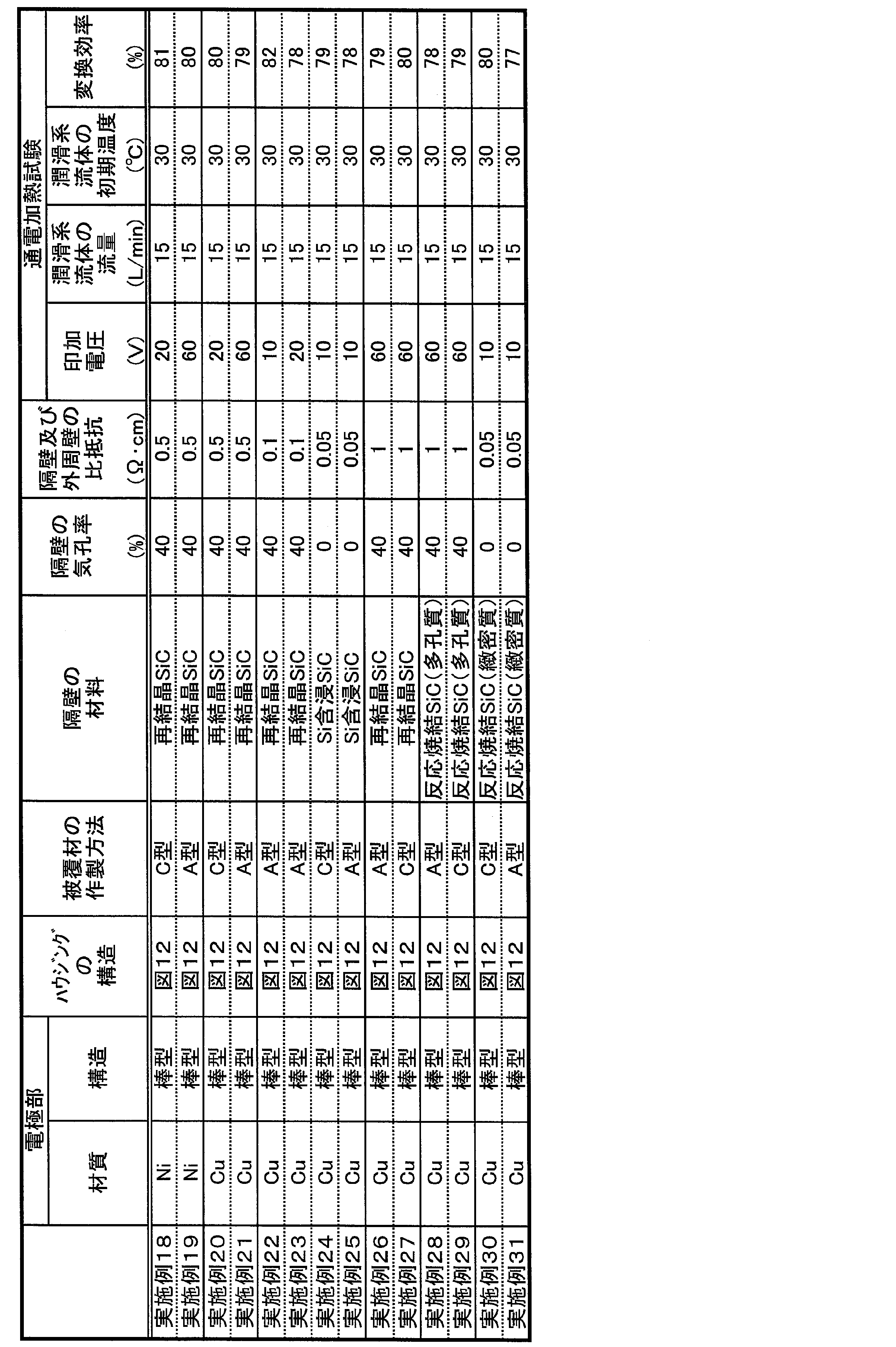
電極部の材質、電極部の構造、ハウジングの構造、被覆材の作製方法、及び隔壁の材料を表3に示すように変更した以外は、実施例1と同様の方法でヒーターを作製した。実施例36~45のヒーターにおいては、断絶材として、厚み5mmのセラミックスファイバーシート(Al2O3-SiO2系)を用いた。 (Examples 32 to 45)
A heater was manufactured in the same manner as in Example 1 except that the material of the electrode portion, the structure of the electrode portion, the structure of the housing, the method of preparing the covering material, and the material of the partition wall were changed as shown in Table 3. In the heaters of Examples 36 to 45, ceramic fiber sheets (Al 2 O 3 -SiO 2 -based) having a thickness of 5 mm were used as the disconnecting material.

電極部の材質、電極部の構造、ハウジングの構造、及び隔壁の材料を表3に示すように変更し、ハウジングが樹脂によって形成されたヒーター(即ち、「ハウジングの構造」が図14のヒーター)を、以下の方法によって作製した。まず、表3に示す隔壁の材料に応じた、ハニカム構造部を有するヒーター本体を作製した。実施例1と同様の方法で、ヒーター本体の外周部分に、被覆材をコーティングして、被覆材を形成した。このヒーター本体とは別に、フッ素系樹脂を用いて、ハウジングを作製した。尚、ハウジングに使用したフッ素系樹脂は、その厚みが5mmのものを用いた。得られた樹脂製のハウジング内に、被覆材を形成したヒーター本体を収納し、更に、ハウジングとヒーター本体との間に、セラミックスファイバーシートの断熱材を配置して、ヒーターを作製した。得られたヒーターを用いて、実施例1と同様の方法で通電加熱試験を行った。通電加熱試験の結果から求められた変換効率(%)を表3に示す。表3に、通電加熱試験における、印加電圧(V)、ヒーター内を通過させる潤滑系流体の流量(L/min)、及び潤滑系流体の初期温度(℃)を示す。 (Examples 46 to 49)
The material of the electrode portion, the structure of the electrode portion, the structure of the housing, and the material of the partition wall are changed as shown in Table 3, and the heater is formed of resin (that is, the “housing structure” is the heater of FIG. 14) Were produced by the following method. First, a heater main body having a honeycomb structure part corresponding to the material of the partition shown in Table 3 was produced. A coating material was coated on the outer peripheral portion of the heater body in the same manner as in Example 1 to form a coating material. Apart from the heater main body, a housing was manufactured using a fluorine-based resin. The fluorine-based resin used for the housing had a thickness of 5 mm. The heater main body in which the covering material was formed was stored in the obtained resin-made housing, and also the heat insulation material of the ceramic fiber sheet was arrange | positioned between a housing and a heater main body, and the heater was produced. The electric-heating test was done by the method similar to Example 1 using the obtained heater. The conversion efficiency (%) obtained from the result of the electric heating test is shown in Table 3. Table 3 shows the applied voltage (V), the flow rate of the lubricating system fluid to be passed through the heater (L / min), and the initial temperature (° C.) of the lubricating system fluid in the conduction heating test.
電極部の材質、電極部の構造、ハウジングの構造、及び隔壁の材料を表3に示すように変更し、図12に示すような構造のヒーターを作製した。本実施例においては、低温動作時を模擬し、潤滑系流体の初期温度を0℃に下げた状態での試験とした。得られたヒーターを用いて、実施例1と同様の方法で通電加熱試験を行った。通電加熱試験の結果から求められた変換効率(%)を表3に示す。表3に、通電加熱試験における、印加電圧(V)、ヒーター内を通過させる潤滑系流体の流量(L/min)、及び潤滑系流体の初期温度(℃)を示す。 (Examples 50 and 51)
The material of the electrode portion, the structure of the electrode portion, the structure of the housing, and the material of the partition wall were changed as shown in Table 3, and a heater having a structure as shown in FIG. 12 was produced. In this example, the low temperature operation was simulated, and the test was performed in a state where the initial temperature of the lubricating system fluid was lowered to 0 ° C. The electric-heating test was done by the method similar to Example 1 using the obtained heater. The conversion efficiency (%) obtained from the result of the electric heating test is shown in Table 3. Table 3 shows the applied voltage (V), the flow rate of the lubricating system fluid to be passed through the heater (L / min), and the initial temperature (° C.) of the lubricating system fluid in the conduction heating test.
表1に示すように、ハウジングの内部に断熱材を配置していない実施例1のヒーターは、67%の変換効率であった。実施例2~51のヒーターと比較して変換効率は低いものの、実施例1のようなセラミックスからなる被覆材によって、十分な断熱効果が発現することが分かった。また、この被覆材は、絶縁性、及びシール性も良好なものであった。また、表1~表3に示すように、更に、被覆材に加えてセラミックスファイバーシートの断熱材を併用したり、ハウジングを樹脂製にすることで、更に変換効率を向上させることができた。また、ハウジングを樹脂製にすることで、ヒーターの軽量化も実現可能であった。実施例50及び51においては、潤滑系流体の初期温度を0℃にまで下げたことから、始動時の粘性が高くなり、初期温度が30℃のものに比較してハニカム通過時の潤滑系流体の圧損は高くなったが、動作上の問題無く、ヒーターとして良好なものであった。 (result)
As shown in Table 1, the heater of Example 1 in which the heat insulating material was not disposed inside the housing had a conversion efficiency of 67%. Although the conversion efficiency was low as compared with the heaters of Examples 2-51, it was found that a sufficient heat insulating effect was exhibited by the coating material made of the ceramic as in Example 1. Moreover, this coating material also had good insulation and sealability. Further, as shown in Tables 1 to 3, the conversion efficiency can be further improved by additionally using a heat insulating material of the ceramic fiber sheet in addition to the covering material or making the housing of resin. Moreover, the weight reduction of a heater was also realizable by making a housing into resin. In Examples 50 and 51, since the initial temperature of the lubricating system fluid was lowered to 0 ° C., the viscosity at the start was higher, and the lubricating system fluid at the time of passing through the honeycomb compared with the one having the initial temperature of 30 ° C. Pressure loss was high, but it was good as a heater without any operational problems.
Claims (10)
- ヒーター本体、前記ヒーター本体を収納するハウジング、及び前記ヒーター本体と前記ハウジングとの間の少なくとも一部に配置され、前記ヒーター本体の少なくとも一部を覆う被覆材、を備え、
前記被覆材が、セラミックス及びガラスの少なくとも一方を含む材料からなり、
前記ヒーター本体が、潤滑系流体の流路となる一方の端面から他方の端面まで延びる複数のセルを区画形成する隔壁を有する筒状のハニカム構造部、及び前記ハニカム構造部の側面に配設された一対の電極部を有し、
前記ハウジングが、前記潤滑系流体が流入する流入口及び前記ヒーター本体に形成された前記セルを通過した前記潤滑系流体が流出する流出口を有し、前記ヒーター本体の側面側を覆うように前記ヒーター本体を収納し、
前記ハニカム構造部の前記隔壁が、セラミックスを主成分とする材料からなり、前記隔壁が通電により発熱するヒーター。 A heater body, a housing for housing the heater body, and a covering material disposed on at least a portion between the heater body and the housing and covering at least a portion of the heater body.
The covering material is made of a material containing at least one of ceramics and glass,
The heater main body is disposed on a side surface of the honeycomb structure portion having a cylindrical shape having a partition that partitions and forms a plurality of cells extending from one end surface to the other end surface to be a flow path of the lubricating system fluid Pair of electrode parts,
The housing has an inlet through which the lubricating system fluid flows, and an outlet through which the lubricating system fluid having passed through the cells formed in the heater body flows out, and the housing covers the side of the heater body. House the heater body,
The heater which the said partition of the said honeycomb structure part becomes from the material which has a ceramic as a main component, and the said partition heat | fever-generates by electricity supply. - 前記被覆材が、前記ヒーター本体の前記一方の端面側における前記ヒーター本体と前記ハウジングとの間、及び前記ヒーター本体の前記他方の端面側における前記ヒーター本体と前記ハウジングとの間に、少なくとも配置されている請求項1に記載のヒーター。 The covering material is disposed at least between the heater main body and the housing on the one end face side of the heater main body and between the heater main body and the housing on the other end face side of the heater main body The heater according to claim 1.
- 前記被覆材が、前記セラミックス及びガラスの少なくとも一方を含む材料を、前記ヒーター本体の表面の少なくとも一部にコーティングしたものである請求項2に記載のヒーター。 The heater according to claim 2, wherein the coating material is a material in which at least one of the ceramic and glass is coated on at least a part of the surface of the heater main body.
- 前記隔壁は、SiC、金属含浸SiC、金属複合SiC、及び金属複合Si3N4からなる群から選ばれる1種を主成分とする請求項1~3のいずれか一項に記載のヒーター。 The heater according to any one of claims 1 to 3, wherein the partition wall is mainly composed of one selected from the group consisting of SiC, metal-impregnated SiC, metal composite SiC, and metal composite Si 3 N 4 .
- 前記一対の電極部の一部が、前記ハウジングを貫通して前記ハウジングの外側まで延設され、
前記被覆材が、前記一対の電極部が前記ハウジングを貫通する部位における前記一対の電極部と前記ハウジングとの間に、少なくとも配置されている請求項1~4のいずれか一項に記載のヒーター。 A part of the pair of electrode parts is extended through the housing to the outside of the housing,
The heater according to any one of claims 1 to 4, wherein the covering material is disposed at least between the pair of electrode portions and the housing at a portion where the pair of electrode portions penetrates the housing. . - 前記被覆材が、少なくとも前記ヒーター本体に配置された前記一対の電極部全域を覆うように、前記ヒーター本体と前記ハウジングとの間に配置されている請求項1~5のいずれか一項に記載のヒーター。 The said covering material is arrange | positioned between the said heater main body and the said housing so that the said whole electrode part area | region arrange | positioned at least to the said heater main body may be covered. Heater.
- 前記一対の電極部のそれぞれが、前記ハニカム構造部の側面に配置された電極基板と、前記電極基板に連結するように配置された棒状の電極部とからなる請求項1~6のいずれか一項に記載のヒーター。 The electrode pair according to any one of claims 1 to 6, wherein each of the pair of electrode parts comprises an electrode substrate arranged on a side surface of the honeycomb structure part and a rod-like electrode part arranged to be connected to the electrode substrate. The heater described in the section.
- 前記ハウジングの材質が、金属、又は樹脂である請求項1~7のいずれか一項に記載のヒーター。 The heater according to any one of claims 1 to 7, wherein a material of the housing is metal or resin.
- 前記ハウジングの内部において、前記ヒーター本体と前記ハウジングとの間に、断熱材が配置されている請求項1~8のいずれか一項に記載のヒーター。 The heater according to any one of claims 1 to 8, wherein a heat insulating material is disposed between the heater main body and the housing inside the housing.
- 前記被覆材の比抵抗が、106Ω・cm以上である請求項1~9のいずれか一項に記載のヒーター。 The heater according to any one of claims 1 to 9, wherein a specific resistance of the coating material is 10 6 Ω · cm or more.
Priority Applications (4)
| Application Number | Priority Date | Filing Date | Title |
|---|---|---|---|
| JP2013529483A JP6060078B2 (en) | 2012-03-22 | 2013-01-23 | heater |
| CN201380000441.5A CN103503557B (en) | 2012-03-22 | 2013-01-23 | Heater |
| EP13731654.3A EP2717649B1 (en) | 2012-03-22 | 2013-01-23 | Heater |
| US13/928,794 US9383119B2 (en) | 2012-03-22 | 2013-06-27 | Heater |
Applications Claiming Priority (2)
| Application Number | Priority Date | Filing Date | Title |
|---|---|---|---|
| JP2012-065656 | 2012-03-22 | ||
| JP2012065656 | 2012-03-22 |
Related Child Applications (1)
| Application Number | Title | Priority Date | Filing Date |
|---|---|---|---|
| US13/928,794 Continuation US9383119B2 (en) | 2012-03-22 | 2013-06-27 | Heater |
Publications (1)
| Publication Number | Publication Date |
|---|---|
| WO2013140845A1 true WO2013140845A1 (en) | 2013-09-26 |
Family
ID=49222313
Family Applications (1)
| Application Number | Title | Priority Date | Filing Date |
|---|---|---|---|
| PCT/JP2013/051293 WO2013140845A1 (en) | 2012-03-22 | 2013-01-23 | Heater |
Country Status (5)
| Country | Link |
|---|---|
| US (1) | US9383119B2 (en) |
| EP (1) | EP2717649B1 (en) |
| JP (1) | JP6060078B2 (en) |
| CN (1) | CN103503557B (en) |
| WO (1) | WO2013140845A1 (en) |
Cited By (3)
| Publication number | Priority date | Publication date | Assignee | Title |
|---|---|---|---|---|
| WO2015083313A1 (en) * | 2013-12-04 | 2015-06-11 | トヨタ自動車株式会社 | Electrically heated catalyst device and method for producing same |
| WO2021171741A1 (en) * | 2020-02-27 | 2021-09-02 | 日本たばこ産業株式会社 | Device |
| RU2796470C1 (en) * | 2020-02-27 | 2023-05-24 | Джапан Тобакко Инк. | Device for heating and spraying smoking substance |
Families Citing this family (25)
| Publication number | Priority date | Publication date | Assignee | Title |
|---|---|---|---|---|
| WO2014170907A2 (en) * | 2013-04-17 | 2014-10-23 | Venkata Sundereswar Rao Vempati | An energy efficient pressure less steam generator |
| CN104502400A (en) * | 2014-11-25 | 2015-04-08 | 航天材料及工艺研究所 | Heat barrier material high temperature heat conductivity plane heat source test system and method |
| JP6131980B2 (en) * | 2015-03-27 | 2017-05-24 | トヨタ自動車株式会社 | Electric heating type catalytic converter |
| KR101967703B1 (en) | 2015-10-05 | 2019-04-10 | 주식회사 엘지화학 | Battery module and battery pack including the same |
| CN108350783B (en) * | 2015-11-16 | 2020-03-24 | 日本碍子株式会社 | Honeycomb type heating device and method of using the same |
| JP7077315B2 (en) * | 2016-10-31 | 2022-05-30 | ワットロー・エレクトリック・マニュファクチャリング・カンパニー | High power density adiabatic exhaust heating system |
| US11535086B2 (en) * | 2016-12-20 | 2022-12-27 | Lg Innotek Co., Ltd. | Heating rod, heating module including same, and heating device including same |
| US20200288541A1 (en) * | 2017-12-28 | 2020-09-10 | International Engineered Environmental Solutions Inc. | Heat-generating device and use thereof |
| US11565335B2 (en) * | 2018-02-02 | 2023-01-31 | Uacj Corporation | Brazing method for brazing material formed of aluminum alloy in inert gas atmosphere without using flux |
| CN108322946B (en) * | 2018-04-18 | 2024-02-13 | 中国工程物理研究院机械制造工艺研究所 | Electric heating type full-closed loop heating device |
| JP7255065B2 (en) * | 2018-10-23 | 2023-04-11 | 日本碍子株式会社 | Heating device, its manufacturing method, and system |
| CN109874185B (en) * | 2019-02-25 | 2022-08-02 | 毕平均 | Heating device and heating equipment |
| US11237031B2 (en) | 2019-08-20 | 2022-02-01 | Rosemount Aerospace Inc. | Additively manufactured heaters for air data probes having a heater layer and a dielectric layer on the air data probe body |
| US11668215B2 (en) * | 2019-10-25 | 2023-06-06 | ECC TEC MSJ Incorporated | Catalytic converter |
| US11237183B2 (en) * | 2019-12-13 | 2022-02-01 | Rosemount Aerospace Inc. | Ceramic probe head for an air data probe with and embedded heater |
| US20230363060A1 (en) | 2020-03-23 | 2023-11-09 | Kanthal Gmbh | Heating element |
| CN111746871B (en) * | 2020-07-10 | 2021-09-17 | 常德仁和盛五金包装制品有限公司 | Sealing device of automatic packaging machine |
| US11565463B2 (en) | 2020-10-20 | 2023-01-31 | Rosemount Aerospace Inc. | Additively manufactured heater |
| US11725835B2 (en) * | 2021-01-02 | 2023-08-15 | Vempati Venkata Sundereswar Rao | Energy efficient and refrigerant-free air cooler |
| US20220212257A1 (en) * | 2021-01-07 | 2022-07-07 | Xerox Corporation | Metal drop ejecting three-dimensional (3d) object printer with a thermally insulated build platform translational mechanism |
| JP2022148668A (en) * | 2021-03-24 | 2022-10-06 | 日本碍子株式会社 | Honeycomb structure, and electric heating support and exhaust gas treatment device each using the honeycomb structure |
| US11731199B2 (en) * | 2021-06-05 | 2023-08-22 | Xerox Corporation | Metal drop ejecting three-dimensional (3D) object printer with double thermal layer insulation for the build platform translational mechanism |
| CA3228841A1 (en) * | 2021-08-13 | 2023-02-16 | Saban Akyildiz | Exhaust system and components thereof |
| US11662235B2 (en) | 2021-10-01 | 2023-05-30 | Rosemount Aerospace Inc. | Air data probe with enhanced conduction integrated heater bore and features |
| US11624637B1 (en) | 2021-10-01 | 2023-04-11 | Rosemount Aerospace Inc | Air data probe with integrated heater bore and features |
Citations (6)
| Publication number | Priority date | Publication date | Assignee | Title |
|---|---|---|---|---|
| JPS6316114A (en) * | 1986-07-08 | 1988-01-23 | Nippon Denso Co Ltd | Heating device for engine oil |
| JPS6331219U (en) * | 1986-08-14 | 1988-02-29 | ||
| JPS6331218U (en) * | 1986-08-14 | 1988-02-29 | ||
| JPH05115796A (en) * | 1991-09-02 | 1993-05-14 | Usui Internatl Ind Co Ltd | Waste gas purifying apparatus |
| JP2000106263A (en) * | 1998-09-30 | 2000-04-11 | Kyocera Corp | Heater and heat roller for fixing |
| JP2011246340A (en) * | 2010-04-28 | 2011-12-08 | Denso Corp | Honeycomb structure and manufacturing method therefor |
Family Cites Families (43)
| Publication number | Priority date | Publication date | Assignee | Title |
|---|---|---|---|---|
| US3265865A (en) * | 1963-10-09 | 1966-08-09 | Armstrong Cork Co | Electrical duct heater |
| JPS5148815B2 (en) * | 1973-03-09 | 1976-12-23 | ||
| US3903341A (en) * | 1973-09-20 | 1975-09-02 | Universal Oil Prod Co | Ceramic honeycomb structure for accommodating compression and tension forces |
| US3982100A (en) * | 1974-10-08 | 1976-09-21 | Universal Oil Products Company | Monolithic honeycomb form electric heating device |
| US3995143A (en) * | 1974-10-08 | 1976-11-30 | Universal Oil Products Company | Monolithic honeycomb form electric heating device |
| US3956614A (en) * | 1975-04-21 | 1976-05-11 | Universal Oil Products Company | Electric current distribution means for a ceramic type of electrical resistance heater element |
| US4177778A (en) * | 1976-07-29 | 1979-12-11 | Nippondenso Co., Ltd. | Carburetors with heating device |
| JPS5827674B2 (en) * | 1978-10-14 | 1983-06-10 | 日本碍子株式会社 | thermoelectric generator |
| US4505107A (en) * | 1981-10-26 | 1985-03-19 | Nippondenso Co., Ltd. | Exhaust gas cleaning apparatus |
| JPH0625613Y2 (en) | 1986-07-11 | 1994-07-06 | トヨタ自動車株式会社 | Oil heater |
| US5232882A (en) * | 1989-05-19 | 1993-08-03 | Sakai Chemical Industry Co., Ltd. | Ozone decomposing reactor regeneration |
| JP2931362B2 (en) * | 1990-04-12 | 1999-08-09 | 日本碍子株式会社 | Resistance control type heater and catalytic converter |
| US5229079A (en) * | 1990-06-29 | 1993-07-20 | Ngk Insulators, Ltd. | Catalytic converter for use in automotive exhaust emission control |
| JP2848970B2 (en) * | 1990-12-21 | 1999-01-20 | 日本碍子株式会社 | Honeycomb heater and catalytic converter |
| KR0140505B1 (en) * | 1991-01-31 | 1998-06-01 | 볼프강 마우스, 지그프리트 나스 | Honeycomb body with non-uniform electric heating |
| DE4129893A1 (en) * | 1991-09-09 | 1993-03-11 | Emitec Emissionstechnologie | ARRANGEMENT FOR MEASURING TEMPERATURE AND / OR HEATING AND USE THEREOF IN A HONEYCOMB BODY, IN PARTICULAR CATALYST CARRIER BODY |
| JP3058995B2 (en) * | 1992-08-18 | 2000-07-04 | 日本碍子株式会社 | Honeycomb heater |
| JP3506747B2 (en) * | 1992-12-15 | 2004-03-15 | 日本碍子株式会社 | Honeycomb heater |
| JPH06254413A (en) * | 1993-03-01 | 1994-09-13 | Ngk Insulators Ltd | Honeycomb with turbulence holes |
| DE4307431C2 (en) * | 1993-03-09 | 1996-06-27 | Emitec Emissionstechnologie | Electrically heatable honeycomb structure divided into sections with additional electrical conductor elements |
| JPH07163888A (en) * | 1993-12-14 | 1995-06-27 | Ngk Insulators Ltd | Honeycomb heater |
| CA2147112A1 (en) * | 1994-05-26 | 1995-11-27 | Kishor Purushottam Gadkaree | Electrically heatable activated carbon bodies for adsorption and desorption applications |
| JP3305505B2 (en) * | 1994-07-29 | 2002-07-22 | 日本碍子株式会社 | Electrode structure |
| JPH1193649A (en) * | 1997-09-18 | 1999-04-06 | Ngk Insulators Ltd | Heater unit |
| JP3901303B2 (en) * | 1997-10-28 | 2007-04-04 | 日本碍子株式会社 | Heater unit |
| JPH11217270A (en) * | 1998-01-30 | 1999-08-10 | Kyocera Corp | Honeycomb structure |
| JP3220119B2 (en) * | 1999-07-26 | 2001-10-22 | 日本ピラー工業株式会社 | Heater support structure |
| DE10051562A1 (en) * | 2000-10-18 | 2002-04-25 | Emitec Emissionstechnologie | Electrically heated honeycomb body used for removing hydrocarbons or nitrogen oxides from I.C. engine exhaust gases comprises two zones with different coatings arranged behind each other in the flow direction |
| JP2002151236A (en) * | 2000-11-07 | 2002-05-24 | Sumitomo Electric Ind Ltd | Fluid heating heater |
| JP2003074789A (en) | 2001-08-30 | 2003-03-12 | Sumitomo Heavy Ind Ltd | Lubricating oil freeze prevention structure of reduction gear |
| US7112306B2 (en) * | 2002-05-06 | 2006-09-26 | Carrier Corporation | Electrodeless ultraviolet discharge fluid remediation |
| EP1533032A4 (en) * | 2002-06-17 | 2007-12-26 | Hitachi Metals Ltd | Ceramic honeycomb structure, process for producing the same and coat material for use in the production |
| US7982166B2 (en) * | 2003-12-24 | 2011-07-19 | Kyocera Corporation | Ceramic heater and method for manufacturing the same |
| US7012226B1 (en) * | 2004-06-02 | 2006-03-14 | Durex International Corporation | Cartridge heater with a release coating |
| US7722828B2 (en) * | 2005-12-30 | 2010-05-25 | Geo2 Technologies, Inc. | Catalytic fibrous exhaust system and method for catalyzing an exhaust gas |
| US7919734B2 (en) * | 2006-07-24 | 2011-04-05 | Ngk Spark Plug Co., Ltd. | Method for manufacturing ceramic heater and ceramic heater |
| US8385041B2 (en) * | 2007-01-25 | 2013-02-26 | Goudy Research, Llc | Honeycomb structure and method of using the structure |
| EP3195929B1 (en) * | 2009-02-27 | 2019-09-25 | Inventys Thermal Technologies Inc. | Parallel passage fluid contactor structure |
| JP2011099405A (en) * | 2009-11-06 | 2011-05-19 | Toyota Motor Corp | Exhaust emission control device |
| US20110206896A1 (en) * | 2010-02-25 | 2011-08-25 | Mark Lee Humphrey | Ceramic Honeycomb Body And Process For Manufacture |
| EP2540382B1 (en) * | 2010-02-26 | 2020-03-25 | NGK Insulators, Ltd. | Honeycomb structure |
| WO2011125228A1 (en) * | 2010-04-09 | 2011-10-13 | イビデン株式会社 | Honeycomb structure |
| JP5691848B2 (en) * | 2010-09-27 | 2015-04-01 | 株式会社デンソー | Honeycomb structure and electrically heated catalyst device |
-
2013
- 2013-01-23 WO PCT/JP2013/051293 patent/WO2013140845A1/en active Application Filing
- 2013-01-23 CN CN201380000441.5A patent/CN103503557B/en not_active Expired - Fee Related
- 2013-01-23 EP EP13731654.3A patent/EP2717649B1/en not_active Not-in-force
- 2013-01-23 JP JP2013529483A patent/JP6060078B2/en not_active Expired - Fee Related
- 2013-06-27 US US13/928,794 patent/US9383119B2/en active Active
Patent Citations (6)
| Publication number | Priority date | Publication date | Assignee | Title |
|---|---|---|---|---|
| JPS6316114A (en) * | 1986-07-08 | 1988-01-23 | Nippon Denso Co Ltd | Heating device for engine oil |
| JPS6331219U (en) * | 1986-08-14 | 1988-02-29 | ||
| JPS6331218U (en) * | 1986-08-14 | 1988-02-29 | ||
| JPH05115796A (en) * | 1991-09-02 | 1993-05-14 | Usui Internatl Ind Co Ltd | Waste gas purifying apparatus |
| JP2000106263A (en) * | 1998-09-30 | 2000-04-11 | Kyocera Corp | Heater and heat roller for fixing |
| JP2011246340A (en) * | 2010-04-28 | 2011-12-08 | Denso Corp | Honeycomb structure and manufacturing method therefor |
Non-Patent Citations (1)
| Title |
|---|
| See also references of EP2717649A4 * |
Cited By (4)
| Publication number | Priority date | Publication date | Assignee | Title |
|---|---|---|---|---|
| WO2015083313A1 (en) * | 2013-12-04 | 2015-06-11 | トヨタ自動車株式会社 | Electrically heated catalyst device and method for producing same |
| WO2021171741A1 (en) * | 2020-02-27 | 2021-09-02 | 日本たばこ産業株式会社 | Device |
| JPWO2021171741A1 (en) * | 2020-02-27 | 2021-09-02 | ||
| RU2796470C1 (en) * | 2020-02-27 | 2023-05-24 | Джапан Тобакко Инк. | Device for heating and spraying smoking substance |
Also Published As
| Publication number | Publication date |
|---|---|
| JPWO2013140845A1 (en) | 2015-08-03 |
| US20130287378A1 (en) | 2013-10-31 |
| EP2717649B1 (en) | 2016-07-27 |
| JP6060078B2 (en) | 2017-01-11 |
| EP2717649A1 (en) | 2014-04-09 |
| CN103503557B (en) | 2016-05-18 |
| CN103503557A (en) | 2014-01-08 |
| US9383119B2 (en) | 2016-07-05 |
| EP2717649A4 (en) | 2015-04-22 |
Similar Documents
| Publication | Publication Date | Title |
|---|---|---|
| WO2013140845A1 (en) | Heater | |
| JP5883299B2 (en) | Heater for heating lubricating fluid | |
| JP2014054934A (en) | Heater | |
| JP5955775B2 (en) | Thermal conduction member | |
| JP5784913B2 (en) | Tube body and exhaust gas system | |
| WO2006016430A1 (en) | Firing kiln and process for producing ceramic member therewith | |
| JPWO2006013652A1 (en) | Continuous firing furnace and method for producing porous ceramic member using the same | |
| JP2010271031A (en) | Ceramics heat exchanger and method of manufacturing the same | |
| CN107701326B (en) | Internal combustion engine and method for coating internal combustion engine components | |
| JP6324150B2 (en) | Heat exchange member and ceramic structure | |
| JP2012037165A (en) | Heat exchange member | |
| JP5852872B2 (en) | Thermal storage structure | |
| CN110307064B (en) | Fluid heating member, fluid heating member complex, and method for manufacturing fluid heating member | |
| JP2013238116A (en) | Fluid heating component | |
| CN104247008A (en) | Flow path member, and heat exchanger and semiconductor device using same | |
| JP6401433B2 (en) | Honeycomb structure | |
| CN106793536A (en) | A kind of flexible electronic preparation method based on microflow control technique | |
| JP6158687B2 (en) | Heat exchange member | |
| JP5894479B2 (en) | heater | |
| JP6093130B2 (en) | heater | |
| JP5883321B2 (en) | heater | |
| JP5869399B2 (en) | Channel member, heat exchanger using the same, and semiconductor device | |
| WO2015053242A1 (en) | Gas circulation member | |
| JP5869374B2 (en) | heater | |
| JP2014070826A (en) | Heat exchange member and heat exchanger |
Legal Events
| Date | Code | Title | Description |
|---|---|---|---|
| ENP | Entry into the national phase |
Ref document number: 2013529483 Country of ref document: JP Kind code of ref document: A |
|
| REEP | Request for entry into the european phase |
Ref document number: 2013731654 Country of ref document: EP |
|
| WWE | Wipo information: entry into national phase |
Ref document number: 2013731654 Country of ref document: EP |
|
| 121 | Ep: the epo has been informed by wipo that ep was designated in this application |
Ref document number: 13731654 Country of ref document: EP Kind code of ref document: A1 |
|
| NENP | Non-entry into the national phase |
Ref country code: DE |