WO2013136943A1 - Blood components separation device, and centrifugal separator - Google Patents
Blood components separation device, and centrifugal separator Download PDFInfo
- Publication number
- WO2013136943A1 WO2013136943A1 PCT/JP2013/054491 JP2013054491W WO2013136943A1 WO 2013136943 A1 WO2013136943 A1 WO 2013136943A1 JP 2013054491 W JP2013054491 W JP 2013054491W WO 2013136943 A1 WO2013136943 A1 WO 2013136943A1
- Authority
- WO
- WIPO (PCT)
- Prior art keywords
- blood
- ring
- centrifuge
- stator
- separation device
- Prior art date
Links
Images


Classifications
-
- A—HUMAN NECESSITIES
- A61—MEDICAL OR VETERINARY SCIENCE; HYGIENE
- A61M—DEVICES FOR INTRODUCING MEDIA INTO, OR ONTO, THE BODY; DEVICES FOR TRANSDUCING BODY MEDIA OR FOR TAKING MEDIA FROM THE BODY; DEVICES FOR PRODUCING OR ENDING SLEEP OR STUPOR
- A61M1/00—Suction or pumping devices for medical purposes; Devices for carrying-off, for treatment of, or for carrying-over, body-liquids; Drainage systems
- A61M1/02—Blood transfusion apparatus
- A61M1/0209—Multiple bag systems for separating or storing blood components
- A61M1/0218—Multiple bag systems for separating or storing blood components with filters
-
- A—HUMAN NECESSITIES
- A61—MEDICAL OR VETERINARY SCIENCE; HYGIENE
- A61M—DEVICES FOR INTRODUCING MEDIA INTO, OR ONTO, THE BODY; DEVICES FOR TRANSDUCING BODY MEDIA OR FOR TAKING MEDIA FROM THE BODY; DEVICES FOR PRODUCING OR ENDING SLEEP OR STUPOR
- A61M1/00—Suction or pumping devices for medical purposes; Devices for carrying-off, for treatment of, or for carrying-over, body-liquids; Drainage systems
- A61M1/02—Blood transfusion apparatus
- A61M1/0209—Multiple bag systems for separating or storing blood components
- A61M1/0231—Multiple bag systems for separating or storing blood components with gas separating means, e.g. air outlet through microporous membrane or gas bag
-
- A—HUMAN NECESSITIES
- A61—MEDICAL OR VETERINARY SCIENCE; HYGIENE
- A61M—DEVICES FOR INTRODUCING MEDIA INTO, OR ONTO, THE BODY; DEVICES FOR TRANSDUCING BODY MEDIA OR FOR TAKING MEDIA FROM THE BODY; DEVICES FOR PRODUCING OR ENDING SLEEP OR STUPOR
- A61M1/00—Suction or pumping devices for medical purposes; Devices for carrying-off, for treatment of, or for carrying-over, body-liquids; Drainage systems
- A61M1/36—Other treatment of blood in a by-pass of the natural circulatory system, e.g. temperature adaptation, irradiation ; Extra-corporeal blood circuits
- A61M1/3693—Other treatment of blood in a by-pass of the natural circulatory system, e.g. temperature adaptation, irradiation ; Extra-corporeal blood circuits using separation based on different densities of components, e.g. centrifuging
- A61M1/3696—Other treatment of blood in a by-pass of the natural circulatory system, e.g. temperature adaptation, irradiation ; Extra-corporeal blood circuits using separation based on different densities of components, e.g. centrifuging with means for adding or withdrawing liquid substances during the centrifugation, e.g. continuous centrifugation
-
- B—PERFORMING OPERATIONS; TRANSPORTING
- B04—CENTRIFUGAL APPARATUS OR MACHINES FOR CARRYING-OUT PHYSICAL OR CHEMICAL PROCESSES
- B04B—CENTRIFUGES
- B04B5/00—Other centrifuges
- B04B5/04—Radial chamber apparatus for separating predominantly liquid mixtures, e.g. butyrometers
- B04B5/0442—Radial chamber apparatus for separating predominantly liquid mixtures, e.g. butyrometers with means for adding or withdrawing liquid substances during the centrifugation, e.g. continuous centrifugation
-
- B—PERFORMING OPERATIONS; TRANSPORTING
- B04—CENTRIFUGAL APPARATUS OR MACHINES FOR CARRYING-OUT PHYSICAL OR CHEMICAL PROCESSES
- B04B—CENTRIFUGES
- B04B7/00—Elements of centrifuges
- B04B7/08—Rotary bowls
-
- F—MECHANICAL ENGINEERING; LIGHTING; HEATING; WEAPONS; BLASTING
- F16—ENGINEERING ELEMENTS AND UNITS; GENERAL MEASURES FOR PRODUCING AND MAINTAINING EFFECTIVE FUNCTIONING OF MACHINES OR INSTALLATIONS; THERMAL INSULATION IN GENERAL
- F16J—PISTONS; CYLINDERS; SEALINGS
- F16J15/00—Sealings
- F16J15/16—Sealings between relatively-moving surfaces
- F16J15/34—Sealings between relatively-moving surfaces with slip-ring pressed against a more or less radial face on one member
- F16J15/3436—Pressing means
- F16J15/344—Pressing means the pressing force being applied by means of an elastic ring supporting the slip-ring
-
- F—MECHANICAL ENGINEERING; LIGHTING; HEATING; WEAPONS; BLASTING
- F16—ENGINEERING ELEMENTS AND UNITS; GENERAL MEASURES FOR PRODUCING AND MAINTAINING EFFECTIVE FUNCTIONING OF MACHINES OR INSTALLATIONS; THERMAL INSULATION IN GENERAL
- F16J—PISTONS; CYLINDERS; SEALINGS
- F16J15/00—Sealings
- F16J15/16—Sealings between relatively-moving surfaces
- F16J15/34—Sealings between relatively-moving surfaces with slip-ring pressed against a more or less radial face on one member
- F16J15/3464—Mounting of the seal
- F16J15/3476—Means for minimising vibrations of the slip-ring
-
- F—MECHANICAL ENGINEERING; LIGHTING; HEATING; WEAPONS; BLASTING
- F16—ENGINEERING ELEMENTS AND UNITS; GENERAL MEASURES FOR PRODUCING AND MAINTAINING EFFECTIVE FUNCTIONING OF MACHINES OR INSTALLATIONS; THERMAL INSULATION IN GENERAL
- F16J—PISTONS; CYLINDERS; SEALINGS
- F16J15/00—Sealings
- F16J15/16—Sealings between relatively-moving surfaces
- F16J15/34—Sealings between relatively-moving surfaces with slip-ring pressed against a more or less radial face on one member
- F16J15/36—Sealings between relatively-moving surfaces with slip-ring pressed against a more or less radial face on one member connected by a diaphragm or bellow to the other member
-
- A—HUMAN NECESSITIES
- A61—MEDICAL OR VETERINARY SCIENCE; HYGIENE
- A61M—DEVICES FOR INTRODUCING MEDIA INTO, OR ONTO, THE BODY; DEVICES FOR TRANSDUCING BODY MEDIA OR FOR TAKING MEDIA FROM THE BODY; DEVICES FOR PRODUCING OR ENDING SLEEP OR STUPOR
- A61M2202/00—Special media to be introduced, removed or treated
- A61M2202/04—Liquids
- A61M2202/0413—Blood
- A61M2202/0427—Platelets; Thrombocytes
-
- A—HUMAN NECESSITIES
- A61—MEDICAL OR VETERINARY SCIENCE; HYGIENE
- A61M—DEVICES FOR INTRODUCING MEDIA INTO, OR ONTO, THE BODY; DEVICES FOR TRANSDUCING BODY MEDIA OR FOR TAKING MEDIA FROM THE BODY; DEVICES FOR PRODUCING OR ENDING SLEEP OR STUPOR
- A61M2205/00—General characteristics of the apparatus
- A61M2205/33—Controlling, regulating or measuring
- A61M2205/3306—Optical measuring means
- A61M2205/331—Optical measuring means used as turbidity change detectors, e.g. for priming-blood or plasma-hemoglubine-interface detection
-
- A—HUMAN NECESSITIES
- A61—MEDICAL OR VETERINARY SCIENCE; HYGIENE
- A61M—DEVICES FOR INTRODUCING MEDIA INTO, OR ONTO, THE BODY; DEVICES FOR TRANSDUCING BODY MEDIA OR FOR TAKING MEDIA FROM THE BODY; DEVICES FOR PRODUCING OR ENDING SLEEP OR STUPOR
- A61M2205/00—General characteristics of the apparatus
- A61M2205/42—Reducing noise
-
- B—PERFORMING OPERATIONS; TRANSPORTING
- B04—CENTRIFUGAL APPARATUS OR MACHINES FOR CARRYING-OUT PHYSICAL OR CHEMICAL PROCESSES
- B04B—CENTRIFUGES
- B04B5/00—Other centrifuges
- B04B5/04—Radial chamber apparatus for separating predominantly liquid mixtures, e.g. butyrometers
- B04B5/0442—Radial chamber apparatus for separating predominantly liquid mixtures, e.g. butyrometers with means for adding or withdrawing liquid substances during the centrifugation, e.g. continuous centrifugation
- B04B2005/0464—Radial chamber apparatus for separating predominantly liquid mixtures, e.g. butyrometers with means for adding or withdrawing liquid substances during the centrifugation, e.g. continuous centrifugation with hollow or massive core in centrifuge bowl
Definitions
- the present invention is used in a blood component separation device having a stator having a blood inlet or a blood component inlet and outlet, and a centrifuge having a rotor rotatably provided to the stator, and the device.
- the present invention relates to a centrifuge.
- blood has been collected by two blood collection methods: whole blood collection and component blood collection.
- the component blood collection is divided into plasma blood collection and platelet blood collection.
- platelets when platelets are required for treatment, it is preferable to collect only the platelets and return the other components to the blood donor.
- a blood component separation device equipped with a centrifuge is used.
- the centrifuge shown in Patent Document 1 includes a stator having an inflow port and an outflow port for blood or blood components, and a rotor provided to be rotatable with respect to the stator.
- the centrifuge rotor is rotated relative to the stator in the blood separator. At that time, the rotor side ring and the stator side ring slide, and abnormal noise is generated.
- the technique of Patent Document 1 discloses that the generation of abnormal noise can be prevented by providing a damping member on the outer periphery of the stator and providing an elastic body at the attachment portion of the rotor side ring.
- the present invention has been made in view of the above circumstances, and an object of the present invention is to provide a blood separation device that does not generate a high sound even if a centrifuge is rotated before blood enters.
- a blood component separation device has the following configuration.
- a blood component separation apparatus having a centrifuge including a stator having an inlet and an outlet for blood or a blood component and a rotor rotatably provided with respect to the stator, the stator and the rotor It is characterized in that the rotary sliding part is sealed by pressing with a predetermined pressing force, and the predetermined pressing force is 500 grams or less.
- the rotor has an annular fixing ring, the stator holds a resin ring that contacts and slides on the fixing ring, and the resin ring.
- a ring cap; the ring cap provides the predetermined pressing force to the resin ring when the centrifuge is set in the blood component separation device; and the rubber hardness of the ring cap Is preferably 60 or more and 66 or less.
- a centrifugal separator has the following configuration.
- a centrifuge having a stator having an inlet and an outlet for blood or blood components, and a rotor provided rotatably with respect to the stator, and being set in a blood component separator
- the rotor has an annular fixing ring
- the stator has a resin ring that contacts and slides with the fixing ring, and a ring cap that holds the resin ring.
- the ring cap is a blood component separation device.
- the predetermined pressure is applied to the resin ring, and the rubber hardness of the ring cap is 60 or more and 66 or less, so that the predetermined pressing force is 500 grams or less. It is characterized by that.
- the blood component separation device of the present invention has the following configuration and effects as follows.
- the present inventor tried various measures for preventing the generation of high noise by changing the roughness of the rotational sliding portion of the stator and the rotor, but it was not possible to reduce the generation of high noise to zero. Finally, it was discovered that the generation of treble is suppressed by setting the rubber hardness of the ring gap to 60 or more and 66 or less. The reason will be described below.
- the rotary sliding part has been pressed with a strong pressing force in order to improve the sealing performance. For this reason, the present inventor has discovered that a stick slip occurs and a high tone is generated when the slip occurs. Therefore, it was considered that if the stick-slip phenomenon could be suppressed, the generation of high sounds could be suppressed, and this was confirmed by experiments.
- the present inventor confirmed that if the rubber hardness is 66 or less with the configuration described in (2) above, the pressing force at the rotational sliding portion of the stator and the rotor can be 500 grams or less.
- the rotor and the stator of the centrifuge are pressed by a predetermined distance.
- the rubber hardness of the ring cap is 66 or more, the elastic deformation amount of the ring cap is small, so that the predetermined pressing force is 500 grams or more, and stick slip occurs.
- the sealing property is lowered, so the rubber hardness is 60 or more.
- the configuration described in (3) above can suppress the generation of treble.
- centrifuge of the present invention has the following configuration and effects as follows.
- the fixing ring when the rotor is rotated without blood flowing into the centrifuge, the fixing ring can suppress stick-slip with respect to the resin ring. Can be suppressed.
- FIG. 10 is an enlarged view of the seal mechanism portion of FIG. 9 in the present embodiment. It is an enlarged view of the seal mechanism part of FIG. 10 of this embodiment. It is a half longitudinal cross-sectional view which shows the state by which the whole blood is supplied in the centrifuge bowl of this embodiment, and the blood component is isolate
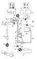
- FIG. 1 shows a system configuration of the blood component separation device 100 of the present embodiment.
- FIG. 16 shows the configuration of the blood component separation device.
- the blood component separation device 100 of this embodiment has a blood component separation circuit 1 as shown in FIG. 16, and the blood component separation circuit 1 has a collection needle 11 and an initial blood collection bag 82 for collecting initial blood.
- An initial blood collection circuit 80 comprising a sampling port 85 and an initial blood collection line 88, a rotor having a blood storage space inside the collection, a centrifugal bowl driving device 15 for rotationally driving the rotor, an inlet 19a and an outlet 19b
- a centrifugal bowl 19 that separates blood into a plurality of blood components by rotation of the rotor, and a first container (plasma bag) 25 and a second container (airbag) that store the blood components separated by the centrifugal bowl 19 ) 28, a third container (platelet intermediate bag) 29, and a first line (the donor tube 12, the first blood pump 13, the tube 44, the first on-off valve 16) connecting the collection needle 11 and the centrifuge bowl 19, Tube 60 and tube 46), the second line (tube 47, tube 48, second on-off valve 24, and tube 58) connecting the centrifuge bowl 19 and the first container 25, the first container 25 and the first container 25.
- a third line (tube 59, second blood pump 18, and tube 45) connecting the lines, and a fourth line (tube 47) connecting the centrifuge bowl 19 and the airbag 28.
- a collection needle 11 for collecting whole blood from a blood donor is connected to one end of a donor tube 12.
- the other end of the donor tube 12 is connected to the first port 13 a of the first blood pump 13.
- the primary blood collection bag 82 is connected to a blood collection needle through a primary blood collection line 88 from a branch portion provided on the donor tube 12.
- the initial blood collection bag 82 further includes a sampling port 85 for transferring the collected initial blood to a test container (not shown).
- the sampling port 85 includes a needle portion 83, a main body portion 86, and a cover portion that covers the needle portion. 84. Further, a clamp 90 for opening and closing the first blood collection line 88 is provided.
- the tube 44 connected to the second port 13 b of the first blood pump 13 is connected to the first port 16 a of the first on-off valve 16.
- a pressure sensor 14 is connected to the donor tube 12.
- the tube 60 connected to the second port 16b of the first on-off valve 16 is branched in two directions.
- One tube 45 is connected to the output port 18b of the second blood pump 18, and the other tube 46 is connected to the inlet 19a of the centrifuge bowl 19 which is a centrifuge. That is, the collection needle 11 and the inlet 19a of the centrifuge bowl 19 are connected by a first line (donor tube 12, first blood pump 13, tube 44, first on-off valve 16, tube 60, and tube 46). .
- the tube 47 connected to the outlet 19b of the centrifuge bowl 19 is branched in two directions, one tube 48 is connected to the input port 24a of the second on-off valve 24, and the other tube 49 is further branched as will be described later.
- the A turbidity sensor 21 and a pressure sensor 22 are attached to the tube 47 connected to the outlet 19b of the centrifuge bowl 19 in the middle thereof.
- an interface sensor 38 for detecting the interface position of the buffy coat layer formed in the centrifugal bowl 19 is attached to the peripheral portion where the centrifugal bowl 19 is attached.
- the output port 24 b of the second on-off valve 24 is connected to the input port 25 a of the plasma bag 25 by a tube 58. That is, the outlet 19b of the centrifuge bowl 19 and the input port 25a of the plasma bag 25 are connected by a second line (tube 47, tube 48, second on-off valve 24, and tube 58).
- the output port 25 b of the plasma bag 25 is connected to the input port 18 a of the second blood pump 18 by a tube 59.
- the output port 18 b of the second blood pump 18 is connected to the tube 45. That is, the output port 25b of the plasma bag 25 and the first line are connected by the third line (the tube 59, the second blood pump 18, and the tube 45).
- the plasma bag 25 is connected so as to communicate with the inlet 19 a and the outlet 19 b of the centrifuge bowl 19, and is communicated or blocked by the functions of the second blood pump 18 and the second opening / closing valve 24.
- the tube 49 branched from the tube 47 is branched into two as described above, one tube 51 is connected to the airbag 28 via the third opening / closing valve 26, and the other tube 52 is the fourth opening / closing. It is connected to the platelet intermediate bag 29 via the valve 27. That is, the outlet 19b of the centrifuge bowl 19 and the airbag 28 are connected by a fourth line (tube 47, tube 49, tube 51, and third on-off valve 26), and the outlet 19b of the centrifuge bowl 19 and platelets.
- the intermediate bag 29 is connected by a fifth line (tube 47, tube 49, tube 52, and fourth on-off valve 27).
- the platelet intermediate bag 29 is connected so as to selectively communicate with the outlet 19b of the centrifuge bowl 19, and is communicated or blocked by the functions of the second on-off valve 24, the third on-off valve 26, and the fourth on-off valve 27. Will be.
- the tube 55 exiting from the platelet intermediate bag 29 is branched in two directions, one tube 56 is connected to the input port 30a of the fifth on-off valve 30, and the other tube 57 is the output port of the third blood pump 34. 34b.
- the input port 34a of the third blood pump 34 is connected to a platelet storage liquid bottle (not shown) through a second sterilizing filter 40 by a platelet bottle needle 35.
- the output port 30 b of the fifth on-off valve 30 is connected to the platelet bag 32 via the leukocyte removal filter 31.
- an airbag 33 is connected to the platelet bag 32.
- an output port 36b of the ACD pump 36 is connected in the middle of the donor tube 12.
- An input port 36 a of the ACD pump 36 is connected to an output port 37 b of the first sterilization filter 37.
- the input port 37 a of the first sterilization filter 37 is connected to the ACD storage bottle by the ACD bottle needle 39.
- Control means include a first blood pump 13, a second blood pump 18, a third blood pump 34, a centrifugal bowl driving device 15, an ACD pump 36, a turbidity sensor 21, an interface sensor 38, a pressure sensor 22, and a first opening / closing.
- the valve 16, the second on-off valve 24, the third on-off valve 26, the fourth on-off valve 27, and the fifth on-off valve 30 are electrically connected.
- the centrifuge bowl 19 is disposed on the centrifuge bowl drive device 15 which is a rotation drive means, and is driven to rotate.
- constituent material of the tube examples include various thermoplastic elastomers such as polyvinyl chloride, polyethylene, polypropylene, polyester such as PET and PBT, ethylene-vinyl acetate copolymer (EVA), polyurethane, and polyester elastomer.
- polyvinyl chloride is particularly preferred.
- Polyvinyl chloride provides sufficient flexibility and flexibility, is easy to handle, and is suitable for clogging with a clamp or the like.
- a polymer obtained by polymerizing or copolymerizing olefin or diolefin such as soft polyvinyl chloride, polyolefin, ethylene, propylene, butadiene, and isoprene in which DEHP is used as a plasticizer
- olefin or diolefin such as soft polyvinyl chloride, polyolefin, ethylene, propylene, butadiene, and isoprene in which DEHP is used as a plasticizer
- EVA ethylene-vinyl acetate copolymer
- PET, PBT, PCGT, etc. can be used.
- polyvinyl chloride is particularly suitable, but a container for storing platelets preferably has excellent gas permeability in order to improve the storage stability of platelets, and polyolefin, DnDP plasticized polyvinyl chloride, etc. are used. It is preferable to use a sheet having a reduced thickness.
- FIG. 8 shows a semi-longitudinal sectional view of the centrifugal bowl 19 of the present embodiment.
- the centrifugal bowl 19 includes a stator 70 and a rotor 75 that can rotate with respect to the stator 70.
- the stator 70 is made of polycarbonate and includes a cylindrical bowl head 74 and a bowl-shaped cover 61 formed to be connected to one end of the bowl head 74.
- the bowl head 74 is provided with an inlet 19a and an outlet 19b.
- An inflow pipe 62 extending to the rotor 75 side is connected to the bowl head 74.
- the inflow pipe 62 is connected to the inflow port 19a to form an in-pipe flow path 621.
- a ring cap 121 made of silicone rubber is provided on the outside of the inflow pipe 62 and on the inside of the cover 61.
- the ring cap 121 is desirably made of a material having an appropriate elasticity and having corrosion resistance.
- the ring cap 121 is formed in a cap shape, and has a structure in which the small diameter side 121 a is fixed to the bowl head 74, and the large diameter side 121 b is fixed to the outer diameter of the resin ring 122 and pressed by the rib 742.
- the ribs 742 are intermittently provided on the inner surface of the cover 61 in the inner circumferential direction.
- a shoulder portion 743 connected to a portion where the cover 61 and the neck portion 741 are connected is formed in a shape that draws a gentle R.
- the resin ring 122 is a ring formed of a hard resin such as a phenol resin, and has a substantially annular shape.
- the resin ring 122 is disposed so as to abut on a fixing ring 125 described later, and is held on the stator 70 side.
- the rotor 75 includes a side wall 73 having a bell shape made of polycarbonate, a shoulder 76 formed by reducing the diameter at one end of the fixing ring 125, and a bottom plate 71 fitted to close the other end of the fixing ring 125. Yes.
- an outer shell 78 and an inner shell 79 are provided inside the fixing ring 125.
- the outer shell 78 has a bell shape and is provided with a support portion 731 intermittently at the end. The support portion 731 is in contact with the inner peripheral side of the shoulder portion 76.
- the side wall 73 has a funnel shape and is fitted to the outer shell 78 at both ends.
- a fixing ring 125 made of ceramic having high sliding resistance such as alumina is fitted into the end portion of the shoulder portion 76, and has a structure in contact with the resin ring 122 described above.
- a substantially disc-shaped bottom channel 130 is formed between the lower surface of the inner shell 79 and the upper surface of the bottom plate 71.
- the bottom plate 71 is a substantially disk-shaped member, and a concave portion for receiving blood flowing down from the in-tube flow path 621 is formed at the center thereof. Further, a bottom channel 130 that extends in a disc shape is formed between the lower surface of the inner shell 79 and the upper surface of the bottom plate 71. The bottom flow path 130 formed between the inner shell 79 and the bottom plate 71 and the in-pipe flow path 621 of the inflow pipe 62 communicate with each other. The bottom channel 130 communicates with a blood storage space 77 formed by the outer periphery of the outer shell 78 and the inner periphery of the side wall 73. The blood reservoir space 77 has a tapered shape such that its inner diameter gradually decreases as it approaches the outlet 19b side. The volume of the blood storage space 77 is preferably about 50 to 1000 ml, and more preferably about 100 to 300 ml.
- FIG. 9 is a side view showing a state before the centrifuge bowl 19 is placed in the blood component separation device 100 and before setting.
- FIG. 10 is a side view showing a state after the centrifugal bowl 19 is placed in the blood component separation device 100 and set.
- FIG. 11 shows an enlarged view of the seal mechanism portion 120.
- FIG. 11 is an enlarged view of FIG.
- FIG. 12 shows an enlarged view of the seal mechanism portion 120.
- FIG. 12 is an enlarged view of FIG.
- the centrifuge bowl 19 is disposed inside the centrifuge tank 110 provided in the blood component separator 100.
- the centrifuge tank 110 is provided with a lid portion 112 and a centrifuge bowl driving device 15, and both the centrifuge tank 110 and the lid portion 112 are formed of a transparent member.
- the lid part 112 is configured to be opened and closed as shown in FIGS.
- the centrifuge bowl driving device 15 is a portion with which the bottom plate 71 of the centrifuge bowl 19 abuts when the centrifuge bowl 19 is inserted into the centrifuge tank 110.
- the seal mechanism portion 120 has a function of sealing against the stator 70 and the rotor 75.
- a ring cap 121 and a resin ring 122 are provided on the stator 70 side, and a fixing ring 125 is provided on the rotor 75 side.
- the resin ring 122 and the fixing ring 125 are brought into contact with each other, thereby exhibiting a sealing function.
- the centrifuge bowl 19 disposed in the centrifuge tank 110 is pressed against the centrifuge bowl drive device 15 side by the shape of the shoulder portion 743 that abuts on the lid 112 when the lid 112 is closed.
- the bottom plate 71 is adsorbed by the centrifugal bowl driving device 15. Since the centrifuge bowl driving device 15 is connected to the rotation driving device, the rotor 75 in contact with the centrifuge bowl driving device 15 can be rotated.
- centrifuge bowl 19 and blood component separation device 100 it is possible to centrifuge whole blood obtained from a donor and collect platelet PLT. Strictly speaking, it is possible to collect a high-concentration platelet PLT solution in which plasma PPP difficult to separate in addition to platelet PLT is mixed. Next, the flow of blood in the centrifuge bowl 19 will be briefly described.
- FIG. 13 shows a half-longitudinal sectional view of the state in which whole blood is supplied into the centrifuge bowl 19 and blood components are separated by centrifugal force.
- the cross section of the centrifuge bowl 19 is shown on the right side of the center line, and the appearance of the centrifuge bowl 19 is shown on the left side of the center line by a broken line.
- the liquid flowing into the centrifuge bowl 19 is carried into the centrifuge bowl 19 from a tube connected to the inlet 19a.
- the in-pipe channel 621 provided in the inlet 19 a and the inflow pipe 62 is connected, and the liquid flowing in from the in-pipe channel 621 is carried to the bottom channel 130.
- the red blood cell RBC layer When blood flows in from the inflow port 19a, in the blood storage space 77 formed by the outer shell 78 and the side wall 73 by the rotation of the rotor 75, the red blood cell RBC layer, the white blood cell, in descending order of specific gravity by centrifugal force.
- a WBC layer, a buffy coat BC layer, a platelet PLT layer, and a plasma PPP layer are formed.
- leukocytes WBC and platelet PLT are close in specific gravity, and are difficult to separate. For this reason, a buffy coat BC layer including leukocytes WBC and platelets PLT is formed.
- the breakdown of whole blood is about 55% for plasma PPP, about 43.2% for red blood cell RBC, about 1.35% for white blood cell WBC, and about 0.45% for platelet PLT.
- the outflow passage 63 formed slightly above the midpoint of the inflow pipe 62 is formed in the inner peripheral portion. Therefore, in the blood storage space 77, the outflow port 19 b from the plasma PPP formed in the inner periphery. And flows out of the centrifuge bowl 19.
- FIG. 2 shows the second step.
- FIG. 3 shows a third step (critical flow step).
- FIG. 4 shows a fourth step (circulation flow step).
- FIG. 5 shows a step of collecting a low-concentration platelet PLT solution in the fifth step (acceleration step).
- FIG. 6 shows a step of storing a high-concentration platelet PLT solution in the fifth step (acceleration step).
- FIG. 7 shows a step of collecting a low-concentration platelet PLT solution in the fifth step (acceleration step).
- the blood component separation device 100 is intended to collect a high-concentration platelet PLT solution.
- the pumps (second blood pump 18, third blood pump 34, and ACD pump 36) shown in FIG. 1 to FIG. 7 are operating in a white display and stopped in a black display. Indicates the state.
- the valves (the first on-off valve 16, the second on-off valve 24, the third on-off valve 26, the fourth on-off valve 27, and the fifth on-off valve 30) are also shown in white, indicating black. It shows a closed state with a fill display.
- the ACD pump 36 and the first blood pump 13 are driven, and an ACD solution for preventing blood coagulation is supplied to the centrifuge bowl 19 through the opened first on-off valve 16, and the centrifuge bowl 19 19 priming steps (first step) are performed.
- the priming is a process in which an ACD solution is attached to the donor tube 12, the first pump, and the portion in contact with the blood in the centrifuge bowl 19 in advance so that the blood does not coagulate when flowing.
- the ACD liquid is supplied from an ACD storage bottle (not shown) to which the ACD bottle needle 39 is connected. From the priming step, the centrifugal bowl 19 is rotated at a predetermined rotational speed.
- the blood collection needle 11 is punctured into the blood donor, and the collection of whole blood is started.
- the ACD pump 36 is driven, and the ACD solution is supplied to the donor tube 12 and mixed with the whole blood.
- Whole blood is supplied to the centrifuge bowl 19.
- the ACD solution is supplied so as to be about 20% of the mixture of whole blood and ACD solution.
- the third on-off valve 26 is closed and the second on-off valve 24 is closed as shown in FIG.
- the plasma PPP overflowing from the centrifuge bowl 19 is stored in the plasma bag 25. This is the second step. Only the plasma PPP comes out from the centrifuge bowl 19 at the beginning.
- a circulation flow step (fourth step) is performed in which the plasma PPP in the plasma bag 25 passes through the second blood pump 18, the centrifugal bowl 19, and the second on-off valve 24 and returns to the plasma bag 25 again.
- plasma PPP is circulated through the centrifuge bowl 19 for about 30 to 40 seconds at a rate of about 100 ml / min.
- the particulate matter concentration in the buffy coat BC is reduced, and the white blood cells WBC having a higher specific gravity than the platelet PLT are deposited outside the buffy coat BC. That is, platelet PLT and leukocyte WBC can be more clearly separated.
- the process enters the acceleration process (fifth process) shown in FIG.
- the acceleration process by controlling the rotation speed of the second blood pump 18, the rotation speed is gradually increased and the flow rate of the plasma PPP is sequentially increased.
- the flow rate is increased by 10 ml / min every few seconds, and the plasma PPP flow rate is accelerated to 200 ml / min in 20-30 seconds. Due to this acceleration, the platelet PLT gains a force in the upward direction and is released from the outflow passage 63 to the outside of the centrifuge bowl 19.
- leukocytes WBC and red blood cells RBC having large specific gravity do not go out of the outflow passage 63 because the centrifugal force is stronger.
- the changes in the concentration of platelet PLT, leukocyte WBC, and red blood cell RBC that flow out first have platelet PLT outflow, and the amount of platelet PLT outflow tends to gradually increase and then gradually decrease beyond the maximum flow rate. Similarly, the leukocyte WBC gradually increases and the flow rate gradually decreases when the maximum flow rate is exceeded.
- the turbidity sensor 21 detects the platelet PLT solution, the second on-off valve 24 is closed and the fourth on-off valve 27 is opened as shown in FIG. Thereby, the platelet PLT solution can be stored in the platelet intermediate bag 29.
- the procedure returns to the blood return step shown in FIG.
- the rotation of the centrifuge bowl 19 is stopped, the first on-off valve 16 is opened, the first blood pump 13 is rotated in the reverse direction, and blood returning to the donor is started to return the blood remaining in the centrifuge bowl 19.
- the reverse speed of the first blood pump 13 is driven at twice the normal speed to shorten the blood return time.
- the second blood pump 18 is driven to return the plasma PPP that has been excessively collected and stored in the plasma bag 25.
- the rotation of the centrifuge bowl 19 is started, the first blood pump 13 is rotated forward again, and blood collection is resumed. Then, the cycle shown in FIGS. 1 to 6 is repeated. This cycle is usually performed for 3 or 4 cycles until a predetermined amount of platelet PLT is secured. In the case of completing in three cycles, when blood return in the third cycle is completed, the collection needle 11 is removed from the blood donor, and blood collection is completed.
- the rotation speed of the centrifuge bowl 19 to be used the centrifuge bowl 19 is rotated at, for example, 500 rpm during the priming operation, and the centrifuge bowl 19 is rotated at, for example, 4000 to 6000 rpm when separating a predetermined blood component. Yes.
- the fifth on-off valve 30 is opened, and the platelet PLT solution stored in the platelet intermediate bag 29 is injected into the platelet bag 32 via the leukocyte removal filter 31. At this time, the air present in the platelet bag 32 moves to the airbag 33. After confirming that all the platelet PLT liquid stored in the platelet intermediate bag 29 has been discharged, the third blood pump 34 is driven, and the platelet bottle needle 35 connected to the platelet storage liquid bottle 2 Platelet preservation solution is injected into the platelet bag 32 through the sterilization filter 40. Thereafter, the two tubes of the platelet bag are sealed. Thereby, the platelet bag 32 in which the high-concentration platelet PLT solution is stored is completed.
- centrifuge bowl 19 of the present embodiment has the above-described configuration, the following operations and effects are achieved.
- the centrifugal bowl 19 of the present embodiment can be placed in the priming process to suppress the generation of high-frequency abnormal noise.
- the centrifugal bowl 19 of the present embodiment has a blood component having a centrifugal bowl 19 including a stator 70 having an inlet 19a and an outlet 19b for blood or blood components, and a rotor 75 rotatably provided to the stator 70.
- the rotational sliding portions of the stator 70 and the rotor 75 are sealed by pressing with a predetermined pressing force, and the predetermined pressing force is 500 grams or less.
- the structure of the seal mechanism portion 120 includes a rotor 75 having an annular fixing ring 125, a resin ring 122 that is a resin ring in which the stator 70 contacts and slides on the fixing ring 125, and a resin ring.
- the rubber hardness is 60 or more and 66 or less.
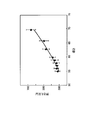
- FIG. 14 is a graph showing the correlation between pressing pressure and vibration acceleration.
- the holding pressure indicates a force for pressing the centrifuge bowl 19 against the centrifuge bowl driving device 15, and its unit is g.
- the vibration acceleration indicates vibration detected by a vibration detector (not shown) attached to the centrifuge tank 110, and its unit is m / s 2 .
- the first group g1 to the sixth group g6 are the results of changing the hardness of the ring cap 121, respectively.
- the first group g1 showing data of vibration acceleration generated between the fixing ring 125 and the resin ring 122 is experimental data when the hardness of the ring cap 121 is set to about 55 to 59.
- the hardness of the ring cap 121 is 60
- the third group g3 is 63
- the fourth group g4 is 66
- the fifth group g5 is 68
- the sixth group g6 is The hardness is set to 70.
- the numerical value shown here as the rubber hardness of the ring cap 121 shows the standard hardness measured by the test method prescribed
- the rubber hardness of the first group g1 to the sixth group g6 is adjusted at the raw material stage, and the rubber hardness of the ring cap 121 is uniform.
- the vibration of the centrifuge tank 110 was detected by changing the rubber hardness of the ring cap 121 and the force pressing the centrifuge bowl 19.
- FIG. 15 is a graph showing the correlation between the hardness of the ring cap 121 and the pressing pressure. From FIG. 15, it can be seen that the pressure of the centrifuge bowl 19 increases linearly by increasing the hardness of the ring cap 121. Therefore, by selecting the hardness of the ring cap 121, it is possible to adjust the pressing pressure against the centrifuge bowl 19. From the results of FIG. 14, the ring cap 121 obtained from the data of the first group g1 to the fourth group g4, that is, the ring cap 121 having a rubber hardness set between 55 and 66 is attached to the centrifuge bowl 19. It can be seen that a pressing pressure of 500 g or less can be realized by using.
- the correlation between the rubber hardness of the ring cap 121 and the pressing pressure of the centrifuge bowl 19 is influenced by how the centrifuge bowl 19 is held with respect to the blood component separator 100. It is considered a thing. That is, when the centrifuge bowl 19 is installed in the blood component separation device 100, the centrifuge bowl 19 is adsorbed and fixed at a predetermined position of the centrifuge bowl driving device 15 disposed in the centrifuge tank 110, and the lid 112 is closed. As described above, the relationship between the centrifuge bowl 19 and the lid portion 112 is set to have a dimensional relationship that interferes with the shoulder portion 743 of the centrifuge bowl 19 when the centrifuge bowl 19 is disposed in the centrifuge bowl driving device 15.
- the centrifugal bowl 19 is pushed down about several millimeters in the direction of the centrifugal bowl driving device 15 along the taper of the shoulder portion 743.
- This pushed-down distance is absorbed by the seal mechanism portion 120, that is, absorbed by deformation of the ring cap 121 as shown in FIGS. Since the deformation of the ring cap 121 depends on the rubber hardness of the ring cap 121, the relationship between the pressing pressure and the rubber hardness as shown in FIG. 15 is shown. That is, the reason why the pressing pressure changes depending on the rubber hardness of the ring cap 121 is due to such a background.
- the pressing pressure of the ring cap 121 can be changed by adjusting the rubber hardness of the ring cap 121, and by making the rubber hardness about 66 or less, the occurrence of abnormal noise due to the stick-slip phenomenon described above can be prevented.
- the fixing ring 125 rotates and moves with respect to the resin ring 122 due to the stick-slip phenomenon, it is considered that the resin ring 122 repeats movement and fixation with respect to the fixing ring 125, and this includes a centrifugal bowl drive device. It is considered that high-frequency abnormal noise was generated due to the relationship with the rotational speed of 15.
- the rubber hardness of the ring cap 121 is preferably 60 or more.
- the hardness of the ring cap 121 is suitably about 60 to 66.
- the holding pressure of the centrifuge bowl 19 is 500 g or less, and abnormal noise generated from the centrifuge bowl 19 is obtained. Can be suppressed.
- the abnormal noise in the high frequency range generated from the centrifuge bowl 19 is confused with the mechanical sound, and may cause anxiety to the blood donor sleeping on the immediate side of the blood component separating apparatus 100 or the worker who collects blood. However, such anxiety can be eliminated by using the centrifuge bowl 19 of the present embodiment.
- the change of the structure of the centrifuge bowl 19 is not hindered. Further, the configuration of the blood component separation device 100 is not prevented from being changed. Moreover, although the material of the centrifuge bowl 19 is also illustrated, it is not prevented from changing this without departing from the spirit of the invention.
Abstract
Description
62 流入管
63 流出通路
70 ステータ
71 底板
72 肩部流路
73 側壁
74 ボウルヘッド
75 ロータ
76 肩部
77 貯血空間
78 外殻
79 内殻
100 血液成分分離装置
110 遠心槽
112 蓋部
120 シール機構部分
121 リングキャップ
122 樹脂リング
125 固定リング
130 底部流路
621 管内流路
731 支持部
741 首部
742 リブ
743 肩部分
BC バフィーコート
PLT 血小板
PPP 血漿
RBC 赤血球
WBC 白血球
61
Claims (4)
- 血液または血液成分の流入口及び流出口を備えるステータと、前記ステータに対して回転可能に設けられたロータとを備える遠心分離器を有する血液成分分離装置において、
前記ステータと前記ロータの回転摺動部位を、所定の押圧力で押圧することによりシールすること、
前記所定の押圧力が、500グラム以下であること、
を特徴とする血液成分分離装置。 In a blood component separation apparatus having a centrifuge comprising a stator having an inlet and an outlet for blood or blood components, and a rotor provided rotatably with respect to the stator,
Sealing the rotating sliding part of the stator and the rotor by pressing with a predetermined pressing force;
The predetermined pressing force is 500 grams or less;
A blood component separation device characterized by the above. - 請求項1に記載する血液成分分離装置において、
前記ロータが、環状の固定リングを有すること、
前記ステータが、前記固定リングと接触し摺動する樹脂リングと、前記樹脂リングを保持するリングキャップを有すること、
前記リングキャップは、前記遠心分離器が前記血液成分分離装置にセットされたときに、前記樹脂リングに対して前記所定の押圧力を与えること、
前記リングキャップのゴム硬さが、60以上、かつ66以下であること、
を特徴とする血液成分分離装置。 In the blood component separation device according to claim 1,
The rotor has an annular fixing ring;
The stator has a resin ring that contacts and slides on the fixing ring, and a ring cap that holds the resin ring;
The ring cap applies the predetermined pressing force to the resin ring when the centrifuge is set in the blood component separation device;
The rubber hardness of the ring cap is 60 or more and 66 or less,
A blood component separation device characterized by the above. - 請求項2に記載する血液成分分離装置において、
前記遠心分離器に血液を流入させない状態で前記ロータを回転させたときに、前記固定リングが前記樹脂リングに対して、スティックスリップを抑制すること、
を特徴とする血液成分分離装置。 The blood component separation device according to claim 2,
When the rotor is rotated in a state where blood does not flow into the centrifuge, the fixing ring suppresses stick-slip with respect to the resin ring,
A blood component separation device characterized by the above. - 血液または血液成分の流入口及び流出口を備えるステータと、前記ステータに対して回転可能に設けられたロータと、を有し、血液成分分離装置にセットされて使用される遠心分離器において、
前記ロータが、環状の固定リングを有すること、
前記ステータが、前記固定リングと接触し摺動する樹脂リングと、前記樹脂リングを保持するリングキャップを有すること、
前記リングキャップは、前記遠心分離器が前記血液成分分離装置にセットされたときに、前記樹脂リングに対して所定の押圧力を与えること、
前記リングキャップのゴム硬さが、60以上、かつ66以下であることにより、前記所定の押圧力が、500グラム以下とされること、
を特徴とする遠心分離器。 In a centrifuge having a stator having an inlet and an outlet for blood or blood components, and a rotor rotatably provided with respect to the stator, and being set and used in a blood component separator,
The rotor has an annular fixing ring;
The stator has a resin ring that contacts and slides on the fixing ring, and a ring cap that holds the resin ring;
The ring cap applies a predetermined pressing force to the resin ring when the centrifuge is set in the blood component separation device;
When the rubber hardness of the ring cap is 60 or more and 66 or less, the predetermined pressing force is 500 grams or less,
A centrifuge characterized by.
Priority Applications (4)
| Application Number | Priority Date | Filing Date | Title |
|---|---|---|---|
| JP2014504755A JP6034366B2 (en) | 2012-03-13 | 2013-02-22 | Blood component separation device and centrifuge |
| CN201380013864.0A CN104168930B (en) | 2012-03-13 | 2013-02-22 | Blood component separation device and whizzer |
| EP13761915.1A EP2826503B1 (en) | 2012-03-13 | 2013-02-22 | Blood components separation device, and centrifugal separator |
| US14/481,603 US20140378292A1 (en) | 2012-03-12 | 2014-09-09 | Blood Components Separation Device, and Centrifugal Separator |
Applications Claiming Priority (2)
| Application Number | Priority Date | Filing Date | Title |
|---|---|---|---|
| JP2012-055878 | 2012-03-13 | ||
| JP2012055878 | 2012-03-13 |
Related Child Applications (1)
| Application Number | Title | Priority Date | Filing Date |
|---|---|---|---|
| US14/481,603 Continuation US20140378292A1 (en) | 2012-03-12 | 2014-09-09 | Blood Components Separation Device, and Centrifugal Separator |
Publications (1)
| Publication Number | Publication Date |
|---|---|
| WO2013136943A1 true WO2013136943A1 (en) | 2013-09-19 |
Family
ID=49160861
Family Applications (1)
| Application Number | Title | Priority Date | Filing Date |
|---|---|---|---|
| PCT/JP2013/054491 WO2013136943A1 (en) | 2012-03-12 | 2013-02-22 | Blood components separation device, and centrifugal separator |
Country Status (5)
| Country | Link |
|---|---|
| US (1) | US20140378292A1 (en) |
| EP (1) | EP2826503B1 (en) |
| JP (1) | JP6034366B2 (en) |
| CN (1) | CN104168930B (en) |
| WO (1) | WO2013136943A1 (en) |
Families Citing this family (6)
| Publication number | Priority date | Publication date | Assignee | Title |
|---|---|---|---|---|
| CA2985151C (en) * | 2015-05-07 | 2023-06-13 | Aenitis Technologies | Multiple blood bag system |
| EP3512577A1 (en) | 2016-09-16 | 2019-07-24 | Fenwal, Inc. | Blood separation systems and methods employing centrifugal and spinning membrane separation techniques |
| EP3705146A3 (en) | 2019-03-05 | 2020-11-25 | Fenwal, Inc. | Collection of mononuclear cells and peripheral blood stem cells |
| EP4238596A3 (en) | 2019-05-23 | 2023-12-13 | Fenwal, Inc. | Centrifugal separation and collection of red blood cells or both red blood cells and plasma |
| EP4238595A3 (en) | 2019-05-23 | 2023-11-29 | Fenwal, Inc. | Adjustment of target interface location between separated fluid components in a centrifuge |
| US11957828B2 (en) | 2019-09-16 | 2024-04-16 | Fenwal, Inc. | Dynamic adjustment of algorithms for separation and collection of blood components |
Citations (6)
| Publication number | Priority date | Publication date | Assignee | Title |
|---|---|---|---|---|
| JPH0545187B2 (en) * | 1985-04-26 | 1993-07-08 | Baxter Int | |
| JPH0714496B2 (en) * | 1988-10-21 | 1995-02-22 | フィルターミスト インターナショナル ピーエルシー | Separator and its operating method |
| JP2001079452A (en) * | 1999-07-15 | 2001-03-27 | Hitachi Koki Co Ltd | Centrifugal machine |
| JP2006247217A (en) | 2005-03-11 | 2006-09-21 | Terumo Corp | Centrifugal separator |
| JP2010119913A (en) * | 2008-11-17 | 2010-06-03 | Hitachi Koki Co Ltd | Centrifugal separator |
| JP4808219B2 (en) * | 2005-08-26 | 2011-11-02 | 巴工業株式会社 | Decanter centrifuge |
Family Cites Families (4)
| Publication number | Priority date | Publication date | Assignee | Title |
|---|---|---|---|---|
| US3565330A (en) * | 1968-07-11 | 1971-02-23 | Cryogenic Technology Inc | Rotary seal and centrifuge incorporating same |
| DE69837541T2 (en) * | 1997-05-20 | 2007-12-13 | Zymequest, Inc., Beverly | Rotary seal for cell treatment systems |
| DE69919029T2 (en) * | 1998-12-24 | 2005-09-08 | Biosafe S.A. | DEVICE FOR BLOOD SEPARATION, ESPECIALLY FOR CONCENTRATING HEMATOPOIETIC STEM CELLS |
| WO2003091126A1 (en) * | 2002-04-26 | 2003-11-06 | Amato Pharmaceutical Products, Ltd. | Packaging container |
-
2013
- 2013-02-22 WO PCT/JP2013/054491 patent/WO2013136943A1/en active Application Filing
- 2013-02-22 EP EP13761915.1A patent/EP2826503B1/en active Active
- 2013-02-22 JP JP2014504755A patent/JP6034366B2/en active Active
- 2013-02-22 CN CN201380013864.0A patent/CN104168930B/en active Active
-
2014
- 2014-09-09 US US14/481,603 patent/US20140378292A1/en not_active Abandoned
Patent Citations (6)
| Publication number | Priority date | Publication date | Assignee | Title |
|---|---|---|---|---|
| JPH0545187B2 (en) * | 1985-04-26 | 1993-07-08 | Baxter Int | |
| JPH0714496B2 (en) * | 1988-10-21 | 1995-02-22 | フィルターミスト インターナショナル ピーエルシー | Separator and its operating method |
| JP2001079452A (en) * | 1999-07-15 | 2001-03-27 | Hitachi Koki Co Ltd | Centrifugal machine |
| JP2006247217A (en) | 2005-03-11 | 2006-09-21 | Terumo Corp | Centrifugal separator |
| JP4808219B2 (en) * | 2005-08-26 | 2011-11-02 | 巴工業株式会社 | Decanter centrifuge |
| JP2010119913A (en) * | 2008-11-17 | 2010-06-03 | Hitachi Koki Co Ltd | Centrifugal separator |
Also Published As
| Publication number | Publication date |
|---|---|
| JP6034366B2 (en) | 2016-11-30 |
| EP2826503B1 (en) | 2017-05-03 |
| US20140378292A1 (en) | 2014-12-25 |
| EP2826503A4 (en) | 2015-11-18 |
| JPWO2013136943A1 (en) | 2015-08-03 |
| CN104168930A (en) | 2014-11-26 |
| CN104168930B (en) | 2016-10-12 |
| EP2826503A1 (en) | 2015-01-21 |
Similar Documents
| Publication | Publication Date | Title |
|---|---|---|
| JP6034366B2 (en) | Blood component separation device and centrifuge | |
| US10426886B2 (en) | Set of containers for use on a blood component centrifugal separator | |
| EP2091593B1 (en) | Apparatus and method for separating a composite liquid into at least two components | |
| US20200078501A1 (en) | Blood Component Separation Device | |
| AU2007292504A1 (en) | Apparatus and method for separating a composite liquid into at least two components | |
| JP6157451B2 (en) | Blood component separator | |
| KR20170034936A (en) | Apheresis bowl with improved vibration characteristics | |
| EP3184131B1 (en) | Centrifugation system with red blood cell barrier | |
| JP2005296675A (en) | Blood component separating apparatus | |
| JP6097758B2 (en) | Blood component separator | |
| JP2006247217A (en) | Centrifugal separator | |
| US10112003B2 (en) | Blood component separation device | |
| JP2006020756A (en) | Centrifugal separator and blood component sampling circuit | |
| JP6087344B2 (en) | Blood component separator | |
| JP6173861B2 (en) | Blood component separator | |
| JP2017070794A (en) | Blood component separation apparatus and blood component separation method |
Legal Events
| Date | Code | Title | Description |
|---|---|---|---|
| 121 | Ep: the epo has been informed by wipo that ep was designated in this application |
Ref document number: 13761915 Country of ref document: EP Kind code of ref document: A1 |
|
| ENP | Entry into the national phase |
Ref document number: 2014504755 Country of ref document: JP Kind code of ref document: A |
|
| NENP | Non-entry into the national phase |
Ref country code: DE |
|
| REEP | Request for entry into the european phase |
Ref document number: 2013761915 Country of ref document: EP |
|
| WWE | Wipo information: entry into national phase |
Ref document number: 2013761915 Country of ref document: EP |