JP6034366B2 - Blood component separation device and centrifuge - Google Patents
Blood component separation device and centrifuge Download PDFInfo
- Publication number
- JP6034366B2 JP6034366B2 JP2014504755A JP2014504755A JP6034366B2 JP 6034366 B2 JP6034366 B2 JP 6034366B2 JP 2014504755 A JP2014504755 A JP 2014504755A JP 2014504755 A JP2014504755 A JP 2014504755A JP 6034366 B2 JP6034366 B2 JP 6034366B2
- Authority
- JP
- Japan
- Prior art keywords
- blood
- centrifuge
- ring
- stator
- bowl
- Prior art date
- Legal status (The legal status is an assumption and is not a legal conclusion. Google has not performed a legal analysis and makes no representation as to the accuracy of the status listed.)
- Active
Links
Images


Classifications
-
- A—HUMAN NECESSITIES
- A61—MEDICAL OR VETERINARY SCIENCE; HYGIENE
- A61M—DEVICES FOR INTRODUCING MEDIA INTO, OR ONTO, THE BODY; DEVICES FOR TRANSDUCING BODY MEDIA OR FOR TAKING MEDIA FROM THE BODY; DEVICES FOR PRODUCING OR ENDING SLEEP OR STUPOR
- A61M1/00—Suction or pumping devices for medical purposes; Devices for carrying-off, for treatment of, or for carrying-over, body-liquids; Drainage systems
- A61M1/02—Blood transfusion apparatus
- A61M1/0209—Multiple bag systems for separating or storing blood components
- A61M1/0218—Multiple bag systems for separating or storing blood components with filters
-
- A—HUMAN NECESSITIES
- A61—MEDICAL OR VETERINARY SCIENCE; HYGIENE
- A61M—DEVICES FOR INTRODUCING MEDIA INTO, OR ONTO, THE BODY; DEVICES FOR TRANSDUCING BODY MEDIA OR FOR TAKING MEDIA FROM THE BODY; DEVICES FOR PRODUCING OR ENDING SLEEP OR STUPOR
- A61M1/00—Suction or pumping devices for medical purposes; Devices for carrying-off, for treatment of, or for carrying-over, body-liquids; Drainage systems
- A61M1/02—Blood transfusion apparatus
- A61M1/0209—Multiple bag systems for separating or storing blood components
- A61M1/0231—Multiple bag systems for separating or storing blood components with gas separating means, e.g. air outlet through microporous membrane or gas bag
-
- A—HUMAN NECESSITIES
- A61—MEDICAL OR VETERINARY SCIENCE; HYGIENE
- A61M—DEVICES FOR INTRODUCING MEDIA INTO, OR ONTO, THE BODY; DEVICES FOR TRANSDUCING BODY MEDIA OR FOR TAKING MEDIA FROM THE BODY; DEVICES FOR PRODUCING OR ENDING SLEEP OR STUPOR
- A61M1/00—Suction or pumping devices for medical purposes; Devices for carrying-off, for treatment of, or for carrying-over, body-liquids; Drainage systems
- A61M1/36—Other treatment of blood in a by-pass of the natural circulatory system, e.g. temperature adaptation, irradiation ; Extra-corporeal blood circuits
- A61M1/3693—Other treatment of blood in a by-pass of the natural circulatory system, e.g. temperature adaptation, irradiation ; Extra-corporeal blood circuits using separation based on different densities of components, e.g. centrifuging
- A61M1/3696—Other treatment of blood in a by-pass of the natural circulatory system, e.g. temperature adaptation, irradiation ; Extra-corporeal blood circuits using separation based on different densities of components, e.g. centrifuging with means for adding or withdrawing liquid substances during the centrifugation, e.g. continuous centrifugation
-
- B—PERFORMING OPERATIONS; TRANSPORTING
- B04—CENTRIFUGAL APPARATUS OR MACHINES FOR CARRYING-OUT PHYSICAL OR CHEMICAL PROCESSES
- B04B—CENTRIFUGES
- B04B5/00—Other centrifuges
- B04B5/04—Radial chamber apparatus for separating predominantly liquid mixtures, e.g. butyrometers
- B04B5/0442—Radial chamber apparatus for separating predominantly liquid mixtures, e.g. butyrometers with means for adding or withdrawing liquid substances during the centrifugation, e.g. continuous centrifugation
-
- B—PERFORMING OPERATIONS; TRANSPORTING
- B04—CENTRIFUGAL APPARATUS OR MACHINES FOR CARRYING-OUT PHYSICAL OR CHEMICAL PROCESSES
- B04B—CENTRIFUGES
- B04B7/00—Elements of centrifuges
- B04B7/08—Rotary bowls
-
- F—MECHANICAL ENGINEERING; LIGHTING; HEATING; WEAPONS; BLASTING
- F16—ENGINEERING ELEMENTS AND UNITS; GENERAL MEASURES FOR PRODUCING AND MAINTAINING EFFECTIVE FUNCTIONING OF MACHINES OR INSTALLATIONS; THERMAL INSULATION IN GENERAL
- F16J—PISTONS; CYLINDERS; SEALINGS
- F16J15/00—Sealings
- F16J15/16—Sealings between relatively-moving surfaces
- F16J15/34—Sealings between relatively-moving surfaces with slip-ring pressed against a more or less radial face on one member
- F16J15/3436—Pressing means
- F16J15/344—Pressing means the pressing force being applied by means of an elastic ring supporting the slip-ring
-
- F—MECHANICAL ENGINEERING; LIGHTING; HEATING; WEAPONS; BLASTING
- F16—ENGINEERING ELEMENTS AND UNITS; GENERAL MEASURES FOR PRODUCING AND MAINTAINING EFFECTIVE FUNCTIONING OF MACHINES OR INSTALLATIONS; THERMAL INSULATION IN GENERAL
- F16J—PISTONS; CYLINDERS; SEALINGS
- F16J15/00—Sealings
- F16J15/16—Sealings between relatively-moving surfaces
- F16J15/34—Sealings between relatively-moving surfaces with slip-ring pressed against a more or less radial face on one member
- F16J15/3464—Mounting of the seal
- F16J15/3476—Means for minimising vibrations of the slip-ring
-
- F—MECHANICAL ENGINEERING; LIGHTING; HEATING; WEAPONS; BLASTING
- F16—ENGINEERING ELEMENTS AND UNITS; GENERAL MEASURES FOR PRODUCING AND MAINTAINING EFFECTIVE FUNCTIONING OF MACHINES OR INSTALLATIONS; THERMAL INSULATION IN GENERAL
- F16J—PISTONS; CYLINDERS; SEALINGS
- F16J15/00—Sealings
- F16J15/16—Sealings between relatively-moving surfaces
- F16J15/34—Sealings between relatively-moving surfaces with slip-ring pressed against a more or less radial face on one member
- F16J15/36—Sealings between relatively-moving surfaces with slip-ring pressed against a more or less radial face on one member connected by a diaphragm or bellow to the other member
-
- A—HUMAN NECESSITIES
- A61—MEDICAL OR VETERINARY SCIENCE; HYGIENE
- A61M—DEVICES FOR INTRODUCING MEDIA INTO, OR ONTO, THE BODY; DEVICES FOR TRANSDUCING BODY MEDIA OR FOR TAKING MEDIA FROM THE BODY; DEVICES FOR PRODUCING OR ENDING SLEEP OR STUPOR
- A61M2202/00—Special media to be introduced, removed or treated
- A61M2202/04—Liquids
- A61M2202/0413—Blood
- A61M2202/0427—Platelets; Thrombocytes
-
- A—HUMAN NECESSITIES
- A61—MEDICAL OR VETERINARY SCIENCE; HYGIENE
- A61M—DEVICES FOR INTRODUCING MEDIA INTO, OR ONTO, THE BODY; DEVICES FOR TRANSDUCING BODY MEDIA OR FOR TAKING MEDIA FROM THE BODY; DEVICES FOR PRODUCING OR ENDING SLEEP OR STUPOR
- A61M2205/00—General characteristics of the apparatus
- A61M2205/33—Controlling, regulating or measuring
- A61M2205/3306—Optical measuring means
- A61M2205/331—Optical measuring means used as turbidity change detectors, e.g. for priming-blood or plasma-hemoglubine-interface detection
-
- A—HUMAN NECESSITIES
- A61—MEDICAL OR VETERINARY SCIENCE; HYGIENE
- A61M—DEVICES FOR INTRODUCING MEDIA INTO, OR ONTO, THE BODY; DEVICES FOR TRANSDUCING BODY MEDIA OR FOR TAKING MEDIA FROM THE BODY; DEVICES FOR PRODUCING OR ENDING SLEEP OR STUPOR
- A61M2205/00—General characteristics of the apparatus
- A61M2205/42—Reducing noise
-
- B—PERFORMING OPERATIONS; TRANSPORTING
- B04—CENTRIFUGAL APPARATUS OR MACHINES FOR CARRYING-OUT PHYSICAL OR CHEMICAL PROCESSES
- B04B—CENTRIFUGES
- B04B5/00—Other centrifuges
- B04B5/04—Radial chamber apparatus for separating predominantly liquid mixtures, e.g. butyrometers
- B04B5/0442—Radial chamber apparatus for separating predominantly liquid mixtures, e.g. butyrometers with means for adding or withdrawing liquid substances during the centrifugation, e.g. continuous centrifugation
- B04B2005/0464—Radial chamber apparatus for separating predominantly liquid mixtures, e.g. butyrometers with means for adding or withdrawing liquid substances during the centrifugation, e.g. continuous centrifugation with hollow or massive core in centrifuge bowl
Description
この発明は、血液または血液成分の流入口及び流出口を備えるステータと、前記ステータに対して回転可能に設けられたロータとを備える遠心分離器を有する血液成分分離装置、及びその装置で使用される遠心分離器に関するものである。 The present invention is used in a blood component separation device having a stator having a blood inlet or a blood component inlet and outlet, and a centrifuge having a rotor rotatably provided to the stator, and the device. The present invention relates to a centrifuge.
従来から、採血方法としては全血採血と成分採血という2つの採血方法によって採血されている。成分採血においては血漿採血と血小板採血とに別れるが、血小板を治療に必要とする場合には、血小板のみを採取し、その他の成分は供血者に返還するという手法が好ましい。血液から血小板を取り出すには、遠心分離器を備える血液成分分離装置が使用されている。 Conventionally, blood has been collected by two blood collection methods: whole blood collection and component blood collection. The component blood collection is divided into plasma blood collection and platelet blood collection. However, when platelets are required for treatment, it is preferable to collect only the platelets and return the other components to the blood donor. In order to take out platelets from blood, a blood component separation device equipped with a centrifuge is used.
特許文献1に示す遠心分離器は、血液または血液成分の流入口及び流出口を備えるステータと、前記ステータに対して回転可能に設けられたロータとを備えている。遠心分離器のロータは、血液分離装置内で、ステータに対して回転される。そのとき、ロータ側リングとステータ側リングとが摺動し、異音が発生する。特許文献1の技術は、ステータの外周に制振部材を設け、また、ロータ側リングの取り付け部に弾性体を設けることにより、異音の発生を防止できることが開示されている。
The centrifuge shown in
しかしながら、特許文献1の技術を用いた遠心分離器においても、以下の問題がある。
However, the centrifuge using the technique of
遠心分離器で血液を遠心分離するためには、まず、血液が入る前に血液の通るチューブや遠心分離器の内面に抗凝固剤をプライミングする必要がある。その後、遠心分離器に血液を入れて遠心分離を行う。特許文献1の技術において、血液が遠心分離器の中に存在するときの異音は低減できたものの、抗凝固剤のプライミング過程で遠心分離器を回転させたときに、高周波数帯付近の音(高音)が発生する問題があった。この高音は、全ての遠心分離器で発生するわけではなく、その発生率は低い。しかしながら、機械音と紛らわしく、作業者及び供血者に不安感を与える問題があった。
In order to centrifuge blood with a centrifuge, it is necessary to prime an anticoagulant on the tube through which blood passes and the inner surface of the centrifuge before blood enters. Thereafter, blood is put into a centrifuge and centrifuged. In the technique of
この発明は、上記事情に鑑みてなされたものであって、その目的は、血液が入る前に遠心分離器を回転させても高音が発生することのない血液分離装置を提供することにある。 The present invention has been made in view of the above circumstances, and an object of the present invention is to provide a blood separation device in which high sound is not generated even if a centrifuge is rotated before blood enters.
上記目的を達成するために、本発明の一態様である血液成分分離装置は、次の構成を有する。 In order to achieve the above object, a blood component separation device according to one embodiment of the present invention has the following configuration.
(1)血液または血液成分の流入口及び流出口を備えるステータと、前記ステータに対して回転可能に設けられたロータとを備える遠心分離器を有する血液成分分離装置において、前記ステータと前記ロータの回転摺動部位を、所定の押圧力で押圧することによりシールすること、前記所定の押圧力が、500グラム以下であること、を特徴とする。 (1) In a blood component separation apparatus having a centrifuge including a stator having an inlet and an outlet for blood or a blood component and a rotor rotatably provided with respect to the stator, the stator and the rotor It is characterized in that the rotary sliding part is sealed by pressing with a predetermined pressing force, and the predetermined pressing force is 500 grams or less.
(2)(1)に記載する血液成分分離装置において、前記ロータが、環状の固定リングを有すること、前記ステータが、前記固定リングと接触し摺動する樹脂リングと、前記樹脂リングを保持するリングキャップを有すること、前記リングキャップは、前記遠心分離器が前記血液成分分離装置にセットされたときに、前記樹脂リングに対して前記所定の押圧力を与えること、前記リングキャップのゴム硬さが、60以上、かつ66以下であること、が好ましい。 (2) In the blood component separation device described in (1), the rotor has an annular fixing ring, the stator holds a resin ring that contacts and slides on the fixing ring, and the resin ring. A ring cap; the ring cap provides the predetermined pressing force to the resin ring when the centrifuge is set in the blood component separation device; and the rubber hardness of the ring cap Is preferably 60 or more and 66 or less.
(3)(2)に記載する血液成分分離装置において、前記遠心分離器に血液を流入させない状態で前記ロータを回転させたときに、前記固定リングが前記樹脂リングに対して、スティックスリップを抑制すること、が好ましい。 (3) In the blood component separation device described in (2), when the rotor is rotated without blood flowing into the centrifuge, the fixing ring suppresses stick slip with respect to the resin ring. It is preferable to do.
また、上記目的を達成するために、本発明の別の態様である遠心分離器は、次の構成を有する。 Moreover, in order to achieve the said objective, the centrifuge which is another aspect of this invention has the following structure.
(4)血液または血液成分の流入口及び流出口を備えるステータと、ステータに対して回転可能に設けられたロータと、を有し、血液成分分離装置にセットされて使用される遠心分離器において、ロータが、環状の固定リングを有すること、ステータが、固定リングと接触し摺動する樹脂リングと、樹脂リングを保持するリングキャップを有すること、リングキャップは、遠心分離器が血液成分分離装置にセットされたときに、樹脂リングに対して所定の押圧力を与えること、リングキャップのゴム硬さが、60以上、かつ66以下であることにより、前記所定の押圧力が、500グラム以下とされること、を特徴とする。 (4) In a centrifuge having a stator having an inlet and an outlet for blood or blood components, and a rotor provided rotatably with respect to the stator, and being set in a blood component separator The rotor has an annular fixing ring, the stator has a resin ring that contacts and slides with the fixing ring, and a ring cap that holds the resin ring. The ring cap is a blood component separation device. The predetermined pressure is applied to the resin ring, and the rubber hardness of the ring cap is 60 or more and 66 or less, so that the predetermined pressing force is 500 grams or less. It is characterized by that.
本発明の血液成分分離装置は、上記構成を有することにより、次のような作用、効果を奏する。 The blood component separation device of the present invention has the following configuration and effects as follows.
本発明者は、ステータとロータの回転摺動部位の粗さを変化させたりして、色々な高音発生防止対策を試みたが、高音発生をゼロとすることはできなかった。最後に、リングギャップのゴム硬さを60以上、かつ66以下とすることにより、高音発生が抑制されることを発見した。以下、その理由を説明する。 The present inventor tried various measures for preventing the generation of high noise by changing the roughness of the rotational sliding portion of the stator and the rotor, but the generation of high noise could not be made zero. Finally, it was discovered that the generation of treble is suppressed by setting the rubber hardness of the ring gap to 60 or more and 66 or less. The reason will be described below.
上記(1)に記載の構成により、摺動面において、ロータがステータに対して、スティックスリップ現象の発生を抑制することができるため、高音の発生を抑えることができる。 With the configuration described in (1) above, since the rotor can suppress the occurrence of the stick-slip phenomenon with respect to the stator on the sliding surface, the generation of high sounds can be suppressed.
従来、回転摺動部位は、シール性を高めるため、強い押圧力で押圧されていた。そのため、スティックスリップが発生し、スリップするときに高音が発生することを、本発明者は発見した。それ故、スティックスリップ現象を抑制できれば、高音の発生を抑制できると考え、それを実験により確認した。 Conventionally, the rotary sliding portion has been pressed with a strong pressing force in order to improve the sealing performance. For this reason, the present inventor has discovered that a stick slip occurs and a high tone is generated when the slip occurs. Therefore, it was considered that if the stick-slip phenomenon could be suppressed, the generation of high sounds could be suppressed, and this was confirmed by experiments.
また、上記(2)に記載の構成により、ゴム硬さを66以下とすれば、ステータとロータの回転摺動部位における押圧力を500グラム以下とできることを、本発明者は確認した。 In addition, the present inventor has confirmed that if the rubber hardness is 66 or less by the configuration described in (2) above, the pressing force at the rotational sliding portion of the stator and the rotor can be 500 g or less.
すなわち、従来の血液成分分離装置では、遠心分離器を装着したときに、遠心分離器のロータとステータが所定の距離押圧されていた。このため、リングキャップのゴム硬さが66以上あると、リングキャップの弾性変形量が少ないため、所定の押圧力が500グラム以上となり、スティックスリップが発生していたのである。また、60以下では、シール性が低下するため、ゴム硬さを60以上としている。 That is, in the conventional blood component separation device, when the centrifuge is mounted, the rotor and the stator of the centrifuge are pressed by a predetermined distance. For this reason, when the rubber hardness of the ring cap is 66 or more, the elastic deformation amount of the ring cap is small, so that the predetermined pressing force is 500 grams or more, and stick slip occurs. On the other hand, if it is 60 or less, the sealing property is lowered, so the rubber hardness is 60 or more.
また、上記(3)に記載の構成により、高音の発生を抑えることができる。 Further, the configuration described in (3) above can suppress the generation of high sounds.
また、本発明の遠心分離器は、上記構成を有することにより、次のような作用、効果を奏する。 In addition, the centrifuge of the present invention has the following configuration and effects as follows.
上記(4)に記載の構成により、遠心分離器に血液を流入させない状態でロータを回転させたときに、固定リングが樹脂リングに対して、スティックスリップを抑制することができるため、高音の発生を抑えることができる。 With the configuration described in (4) above, when the rotor is rotated without blood flowing into the centrifuge, the fixing ring can suppress stick-slip with respect to the resin ring. Can be suppressed.
まず、本発明の実施形態について、図面を用いて説明する。 First, an embodiment of the present invention will be described with reference to the drawings.
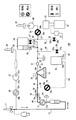
図1に、本実施形態の血液成分分離装置100のシステム構成を示す。図16に、血液成分分離装置の構成を示す。本実施形態の血液成分分離装置100は、図16に示すように血液成分分離回路1を有し、血液成分分離回路1は、採取針11と、初流血を採取するための初流血採取バッグ82、サンプリングポート85、初流血採取ライン88とからなる初流血採取回路80と、採取内部に貯血空間を有するロータと、ロータを回転駆動する遠心ボウル駆動装置15と、流入口19aと流出口19bとを有する。そして、ロータの回転により複数の血液成分に血液を分離する遠心ボウル19と、遠心ボウル19により分離された血液成分を貯留する、第1の容器(血漿バッグ)25、第2の容器(エアバッグ)28、第3の容器(血小板中間バッグ)29、と、採取針11と遠心ボウル19とを接続する第1ライン(ドナーチューブ12、第1血液ポンプ13、チューブ44、第1開閉弁16、チューブ60、及びチューブ46)、遠心ボウル19と第1の容器25とを接続する第2ライン(チューブ47、チューブ48、第2開閉弁24、及びチューブ58)、第1の容器25と第1ラインとを接続する第3ライン(チューブ59、第2血液ポンプ18、及びチューブ45)、遠心ボウル19とエアバッグ28とを接続する第4ライン(チューブ47、チューブ49、チューブ51、及び第3開閉弁26)、遠心ボウル19と第3の容器29とを接続する第5ライン(チューブ47、チューブ49、チューブ52、及び第4開閉弁27)とからなる。
In FIG. 1, the system configuration | structure of the blood
供血者から全血を採取するための採取針11は、ドナーチューブ12の一端に接続している。ドナーチューブ12の他端は、第1血液ポンプ13の第1ポート13aに接続している。初流血採取バッグ82は、ドナーチューブ12上に設けられた分岐部から初流血採取ライン88により採血針と接続される。初流血採取バッグ82はさらに、採取した初流血を図示しない検査容器に移送するためのサンプリングポート85を備え、サンプリングポート85は、針部83と、本体部86と、針部をカバーするカバー部84からなる。また、初流血採取ライン88上にはラインを開閉するためのクレンメ90が設けられている。第1血液ポンプ13の第2ポート13bに接続するチューブ44は、第1開閉弁16の第1ポート16aに接続している。ドナーチューブ12には、圧力センサ14が接続している。第1開閉弁16の第2ポート16bに接続するチューブ60は、2方に分岐される。一方のチューブ45は、第2血液ポンプ18の出力ポート18bに接続し、他方のチューブ46は、遠心分離器である遠心ボウル19の流入口19aに接続している。すなわち、採取針11と遠心ボウル19の流入口19aとは第1ライン(ドナーチューブ12、第1血液ポンプ13、チューブ44、第1開閉弁16、チューブ60、及びチューブ46)によって接続されている。
A
遠心ボウル19の流出口19bに接続するチューブ47は2方に分岐され、一方のチューブ48は第2開閉弁24の入力ポート24aに接続し、他方のチューブ49は、後述するように更に分岐される。遠心ボウル19の流出口19bと接続するチューブ47には、その途中に濁度センサ21、及び圧力センサ22が取り付けられている。また、遠心ボウル19が取り付けられている周辺部には、遠心ボウル19内に形成されるバフィーコート層の界面位置を検出するための界面センサ38が取り付けられている。第2開閉弁24の出力ポート24bはチューブ58により、血漿バッグ25の入力ポート25aに接続している。すなわち、遠心ボウル19の流出口19bと血漿バッグ25の入力ポート25aとは第2ライン(チューブ47、チューブ48、第2開閉弁24、及びチューブ58)によって接続されている。
The
血漿バッグ25の出力ポート25bは、チューブ59により、第2血液ポンプ18の入力ポート18aに接続している。そして、第2血液ポンプ18の出力ポート18bは、チューブ45に接続している。すなわち、血漿バッグ25の出力ポート25bと第1ラインとは第3ライン(チューブ59、第2血液ポンプ18、及びチューブ45)によって接続されている。これにより、血漿バッグ25は遠心ボウル19の流入口19a及び流出口19bと連通するように接続され、第2血液ポンプ18及び第2開閉弁24の働きによって連通もしくは遮断されることになる。
The
チューブ47から分岐された、チューブ49は前述したように2つに分岐され、一方のチューブ51は、第3開閉弁26を介してエアバッグ28に接続し、他方のチューブ52は、第4開閉弁27を介して血小板中間バッグ29に接続している。すなわち、遠心ボウル19の流出口19bとエアバッグ28とは第4ライン(チューブ47、チューブ49、チューブ51、及び第3開閉弁26)によって接続されており、遠心ボウル19の流出口19bと血小板中間バッグ29とは第5ライン(チューブ47、チューブ49、チューブ52、及び第4開閉弁27)によって接続されている。これにより、血小板中間バッグ29は遠心ボウル19の流出口19bと選択的に連通するように接続され、第2開閉弁24、第3開閉弁26、第4開閉弁27の働きによって連通もしくは遮断されることになる。
The
血小板中間バッグ29から出たチューブ55は、2方に分岐され、一方のチューブ56は、第5開閉弁30の入力ポート30aに接続し、他方のチューブ57は、第3血液ポンプ34の出力ポート34bに接続している。第3血液ポンプ34の入力ポート34aは、第2除菌フィルタ40を介して、血小板用瓶針35により図示しない血小板保存液瓶に接続している。第5開閉弁30の出力ポート30bは、白血球除去フィルタ31を介して、血小板バッグ32に接続している。また、血小板バッグ32には、エアバッグ33が接続している。
The
一方、ドナーチューブ12の途中には、ACDポンプ36の出力ポート36bが接続されている。ACDポンプ36の入力ポート36aは、第1除菌フィルタ37の出力ポート37bに接続されている。第1除菌フィルタ37の入力ポート37aはACD用瓶針39によりACD貯蔵瓶に接続している。
On the other hand, in the middle of the
図示しない制御手段に、第1血液ポンプ13、第2血液ポンプ18、第3血液ポンプ34、遠心ボウル駆動装置15、ACDポンプ36、濁度センサ21、界面センサ38、圧力センサ22、第1開閉弁16、第2開閉弁24、第3開閉弁26、第4開閉弁27、及び第5開閉弁30が電気的に接続されている。遠心ボウル19は、回転駆動手段である遠心ボウル駆動装置15上に配置され、回転駆動される。
Control means (not shown) include a
チューブの構成材料としては、たとえば、ポリ塩化ビニル、ポリエチレン、ポリプロピレン、PETやPBTなどのポリエステル、エチレン-酢酸ビニル共重合体(EVA)、ポリウレタン、ポリエステルエラストマー、などの各種熱可塑性エラストマーが挙げられるが、その中でも特にポリ塩化ビニルが好ましい。ポリ塩化ビニルであれば、十分な可撓性、柔軟性が得られるうえ、取り扱いが容易であり、クレンメ等による閉塞にも適している。 Examples of the constituent material of the tube include various thermoplastic elastomers such as polyvinyl chloride, polyethylene, polypropylene, polyester such as PET and PBT, ethylene-vinyl acetate copolymer (EVA), polyurethane, and polyester elastomer. Of these, polyvinyl chloride is particularly preferred. Polyvinyl chloride provides sufficient flexibility and flexibility, is easy to handle, and is suitable for clogging with a clamp or the like.
バッグを構成する材料としては、可塑剤としてDEHPが用いられている軟質のポリ塩化ビニル、ポリオレフィン、エチレン、プロピレン、ブタジエン、イソプレンなどのオレフィンあるいはジオレフィンを重合、共重合した重合体を使用でき、エチレン-酢酸ビニル共重合体(EVA)、EVAと各種熱可塑性エラストマーとのポリマーブレンドなど、これらを各種任意に組み合わせたものが挙げられる。さらに、PET,PBT,PCGTなども用いることが可能である。これらの中でも特にポリ塩化ビニルが好適であるが、血小板を保存する容器には血小板の保存性を向上させるため、ガス透過性に優れたものが好ましく、ポリオレフィンやDnDP可塑化ポリ塩化ビニルなどを用いたり、シートの厚さを薄くしたものを用いたりすることが好ましい。 As a material constituting the bag, a polymer obtained by polymerizing or copolymerizing olefin or diolefin such as soft polyvinyl chloride, polyolefin, ethylene, propylene, butadiene, and isoprene in which DEHP is used as a plasticizer can be used. Examples thereof include ethylene-vinyl acetate copolymer (EVA), polymer blends of EVA and various thermoplastic elastomers, and any combination thereof. Furthermore, PET, PBT, PCGT, etc. can be used. Among these, polyvinyl chloride is particularly suitable, but a container for storing platelets preferably has excellent gas permeability in order to improve the storage stability of platelets, and polyolefin, DnDP plasticized polyvinyl chloride, etc. are used. It is preferable to use a sheet having a reduced thickness.
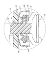
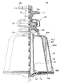
図8に、本実施形態の遠心ボウル19の半縦断面図を示す。説明のため、中心線より右側に遠心ボウル19の断面を、中心線より左側に遠心ボウル19の外観を示している。遠心ボウル19は、ステータ70と、ステータ70に対して回転可能なロータ75とで構成されている。ステータ70は、ポリカーボネート製で、筒状のボウルヘッド74とボウルヘッド74の一端に接続して形成されるお椀形状のカバー61とを備えている。ボウルヘッド74には流入口19aと流出口19bとが設けられている。また、ボウルヘッド74にはロータ75側に延設した流入管62が連結されている。流入管62は流入口19aと接続して管内流路621を形成している。
FIG. 8 shows a semi-longitudinal sectional view of the
流入管62の外側であってカバー61の内側にあたる部分には、シリコーンゴム製のリングキャップ121が備えられている。リングキャップ121は適度の弾力を有し、耐食性を有した素材が用いられることが望ましい。また、リングキャップ121はキャップ状に形成され、小径側121aがボウルヘッド74に固定され、大径側121bが樹脂リング122の外径に固着され、リブ742とで押さえられる構造となっている。リブ742はカバー61の内面に、内周方向に向かって間欠的に備えられている。カバー61と首部741とが接続する部分に接続する肩部分743は、なだらかなRを描く形状に形成されている。樹脂リング122は、フェノール樹脂等の硬質樹脂で形成されたリングであり、略環状に形成されている。樹脂リング122は後述する固定リング125と当接するよう配置されており、ステータ70側に保持されている。
A
ロータ75は、ポリカーボネート製の釣り鐘状をなす側壁73と、固定リング125の一端に縮径して形成された肩部76と、固定リング125の他端を塞ぐように嵌め込まれる底板71を備えている。また、固定リング125の内部には外殻78と内殻79とを備えている。外殻78は釣り鐘形状で、端部に間欠的に支持部731を備えている。この支持部731で肩部76の内周側と当接する構造となっている。また、側壁73はロート状で、両端で外殻78と嵌め合う構造となっている。肩部76の端部にはアルミナ等の耐摺動性の高いセラミックスを用いた固定リング125が嵌め込まれており、前述する樹脂リング122と当接する構造となっている。内殻79の下面と底板71の上面との間には、ほぼ円盤状の底部流路130が形成されている。
The
底板71は、略円盤状の部材であり、その中心部には管内流路621より流下した血液を受ける凹部が形成されている。また、内殻79の下面と底板71の上面との間には、ほぼ円盤状に広がる底部流路130が形成されている。内殻79と底板71の間に形成される底部流路130と、流入管62の管内流路621とは連通している。また、底部流路130は、外殻78の外周と側壁73の内周とで形成される貯血空間77と連通している。貯血空間77は流出口19b側に近づくにつれて、その内径が漸減するようなテーパ形状を成している。貯血空間77の容積は50〜1000ml程度とするのが好ましく、100〜300ml程度とするのがより好ましい。
The
図9に、遠心ボウル19を血液成分分離装置100に配置し、セット前の状況を示した側面図である。図10に、遠心ボウル19を血液成分分離装置100に配置し、セット後の状況を示した側面図である。図11に、シール機構部分120の拡大図を示す。図11は図9の拡大図にあたる。図12に、シール機構部分120の拡大図を示す。図12は図10の拡大図にあたる。血液成分分離装置100に備えられた遠心槽110の内部に、遠心ボウル19は配置される。遠心槽110には蓋部112と遠心ボウル駆動装置15が備えられ、遠心槽110と蓋部112は共に透明の部材で形成されている。蓋部112は図9及び図10に示される様に開閉可能な構成となっている。蓋部112を閉めると遠心ボウル19の肩部分743に当接し、遠心ボウル19を押し下げながら蓋部112と首部741が当接する。遠心ボウル駆動装置15は、遠心ボウル19が遠心槽110に挿入された際に、遠心ボウル19の有する底板71が当接する部分である。
FIG. 9 is a side view showing a state before setting the
シール機構部分120は、ステータ70とロータ75と当接してシールする機能を有する。ステータ70側にはリングキャップ121と樹脂リング122とが備えられ、ロータ75側には固定リング125が備えられている。そして、樹脂リング122と固定リング125とが当接することで、シール機能を発揮する。遠心槽110内に配置された遠心ボウル19は、蓋部112が閉まることで、蓋部112に当接する肩部分743の形状によって遠心ボウル19が遠心ボウル駆動装置15側に押し付けられる。この結果、底板71は、遠心ボウル駆動装置15に吸着等される。遠心ボウル駆動装置15は回転駆動装置と連結されているので、遠心ボウル駆動装置15に当接するロータ75を回転させることが出来る。
The
このような構成の遠心ボウル19及び血液成分分離装置100によって、供血者から得た全血を遠心分離し、血小板PLTを採取することが可能となる。厳密には血小板PLTに加えて分離の難しい血漿PPPが混入した高濃度の血小板PLT液を採取することが可能である。次に、遠心ボウル19内の血液の流れについて簡単に説明する。
By using the
図13には、遠心ボウル19内に全血が供給され、遠心力により血液成分が分離されている状態の半縦断面図を示している。説明のため、中心線より右側に遠心ボウル19の断面を、中心線より左側に遠心ボウル19の外観を破線で示している。遠心ボウル19に流入する液体は、流入口19aに接続されるチューブより遠心ボウル19の内部に運ばれる。流入口19aと流入管62に備えられる管内流路621は接続されており、管内流路621より流入する液体は底部流路130に運ばれる。底部流路130では回転するロータ75の影響によってロータ75の外周方向に血液が運ばれ、貯血空間77に液体が移動する。遠心分離された液体は、貯血空間77から肩部流路72を通過し、流出通路63を通過して、遠心ボウル駆動装置15による遠心力の影響を受けて肩部76の内壁を沿って移動し、流出口19bまで運ばれる。
FIG. 13 shows a semi-longitudinal sectional view of a state where whole blood is supplied into the
流入口19aから血液が流入した場合には、ロータ75の回転によって、外殻78と側壁73とで形成される貯血空間77では、遠心力により、外側から比重の大きい順に、赤血球RBC層、白血球WBC層、バフィーコートBC層、血小板PLT層、血漿PPP層が形成される。ここで、白血球WBCと血小板PLTとは比重が近いため、分離しにくい。このため、白血球WBCと血小板PLTとを含むバフィーコートBC層が形成される。一般的に、全血の内訳は、血漿PPPが約55%、赤血球RBCが約43.2%、白血球WBCが約1.35%、血小板PLTが約0.45%である。遠心ボウル19では、流入管62の中間点より少し上側に形成された流出通路63が内周部に形成されているため、貯血空間77において、内周に形成されている血漿PPPから流出口19bを通過して、遠心ボウル19の外へ流出する。
When blood flows in from the
次に、上記構成を有する血液成分分離装置の作用について、図1乃至図7を用いて説明する。図2には、第2工程を示している。図3には、第3工程(クリティカルフロー工程)を示している。図4には、第4工程(循環フロー工程)を示している。図5には、第5工程(加速工程)のうち、低濃度の血小板PLT液の回収する工程を示している。図6には、第5工程(加速工程)のうち、高濃度の血小板PLT液の貯蔵する工程を示している。図7には、第5工程(加速工程)のうち、低濃度の血小板PLT液の回収する工程を示している。血液成分分離装置100では、高濃度の血小板PLT液を採取することを目的としている。なお、図1乃至図7に示すポンプ(第2血液ポンプ18、第3血液ポンプ34、及びACDポンプ36)は、白抜き表示で稼働していることを示し、黒塗り表示で停止している状態を示している。同様に、バルブ(第1開閉弁16、第2開閉弁24、第3開閉弁26、第4開閉弁27、及び第5開閉弁30)についても白抜き表示で開いていることを示し、黒塗り表示で閉じている状態を示している。
Next, the operation of the blood component separation apparatus having the above configuration will be described with reference to FIGS. FIG. 2 shows the second step. FIG. 3 shows a third step (critical flow step). FIG. 4 shows a fourth step (circulation flow step). FIG. 5 shows a step of collecting a low-concentration platelet PLT solution in the fifth step (acceleration step). FIG. 6 shows a step of storing a high-concentration platelet PLT solution in the fifth step (acceleration step). FIG. 7 shows a step of collecting a low-concentration platelet PLT solution in the fifth step (acceleration step). The blood
始めに、ACDポンプ36及び第1血液ポンプ13が駆動され、血液の凝固を防止するためのACD液が、開かれている第1開閉弁16を介して、遠心ボウル19に供給され、遠心ボウル19のプライミング工程(第1工程)が行われる。プライミングとは、血液を流したときに凝固しないように、予め、ドナーチューブ12、第1ポンプ、及び遠心ボウル19内の血液に接触する部分にACD液を付着させる工程である。ACD液はACD用瓶針39が接続される図示しないACD貯蔵瓶から供給される。プライミング工程から遠心ボウル19は所定の回転速度で回転されている。プライミング工程が終わると、図1に示すように、採取針11を供血者に穿刺し、全血の採取を開始する。このときも、ACDポンプ36が駆動され、ACD液がドナーチューブ12に供給され、全血に混ぜられる。遠心ボウル19に全血が供給される。ここで、ACD液は、全血とACD液の混合液のうち、20%程度となるように、供給される。
First, the
回転している遠心ボウル19に全血が供給されると、図1に示すように、遠心ボウル19の内周部に位置する流出部より、血漿PPPに押されて、遠心ボウル19内の空気(点線で示す。)が流れ出る。流れ出た空気は、開かれている第3開閉弁26を介して、エアバッグ28に貯えられる。遠心ボウル19では、供給された全血に遠心ボウル19内で遠心力を付与されることにより、全血が各成分に分離される。
When the whole blood is supplied to the
次に、濁度センサ21が、チューブ47内を流れる流体が、空気から血漿PPPに変化したことを検出すると、図2に示すように、第3開閉弁26を閉じて、第2開閉弁24を開いて、遠心ボウル19からあふれ出た血漿PPPを血漿バッグ25に貯える。これが第2工程である。遠心ボウル19から始めのうち出てくるのは、血漿PPPのみである。
Next, when the
次に、血漿バッグ25にある程度の血漿PPP(本実施形態では30ml)が貯えられたら、図3に示すように、第2血液ポンプ18を駆動して、供血者から全血を採取すると共に、血漿バッグ25に貯えられている血漿PPPを全血に混ぜて、遠心ボウル19に供給する。これが第3工程(クリティカルフロー工程)である。
Next, when a certain amount of plasma PPP (30 ml in this embodiment) is stored in the
次に、バフィーコートBCと血小板PLTとの界面が所定の位置に来たことを、界面センサ38が検出すると、図4に示すように、第1開閉弁16を閉じて、第2血液ポンプ18を駆動したままで、血漿バッグ25内の血漿PPPを第2血液ポンプ18、遠心ボウル19、第2開閉弁24を通って、再び血漿バッグ25に戻す循環フロー工程(第4工程)を行う。本実施形態の循環フロー工程では、血漿PPPを100ml/分程度の速度で30〜40秒程度、遠心ボウル19内通過して循環させる。これにより、バフィーコートBCにおける粒状物濃度の低減が起き、血小板PLTと比較して、より比重の大きい白血球WBCがバフィーコートBCの外側に沈積することになる。すなわち、血小板PLTと白血球WBCとをより明確に分離できるのである。
Next, when the
次に、循環フロー工程を一定時間行った後、図5に示す加速工程(第5工程)に入る。加速工程では、第2血液ポンプ18の回転数を制御することにより、徐々に回転数を高めて血漿PPPの流量を、順次増分する。本実施形態では、100ml/分から始めて、数秒毎に10ml/分ずつ流量を増加させ、20〜30秒で200ml/分となるまで血漿PPPの流量を加速する。この加速により、血小板PLTは、上昇する方向に力を得て、流出通路63から遠心ボウル19の外部へと放出される。この加速によっては、比重の大きい白血球WBCや赤血球RBCは、遠心力のほうが強いため、流出通路63から出ていくことはない。
Next, after the circulation flow process is performed for a predetermined time, the process enters the acceleration process (fifth process) shown in FIG. In the acceleration process, by controlling the rotation speed of the
血小板PLT、白血球WBC、及び赤血球RBCの流出する濃度変化は、始めに血小板PLTの流出があり、血小板PLTの流出量は徐々に増加し、最大流量を過ぎると徐々に減少するという傾向にある。白血球WBCも同様に、流出量は徐々に増加し、最大流量を過ぎると徐々に減少する。そして、濁度センサ21が、血小板PLT液を検出すると、図5に示すように、第2開閉弁24を閉じて、第4開閉弁27を開く。これにより、血小板PLT液を血小板中間バッグ29に貯えることができる。
The change in the concentration of platelet PLT, leukocyte WBC, and red blood cell RBC that flows out tends to cause the outflow of platelet PLT first, and the outflow amount of platelet PLT gradually increases and then gradually decreases after the maximum flow rate is exceeded. Similarly, the leukocyte WBC gradually increases and the flow rate gradually decreases when the maximum flow rate is exceeded. When the
次に、濁度センサ21が検出する血小板PLTの濃度が所定値を下回ると、図6に示す返血工程に移行する。遠心ボウル19の回転を停止し、第1開閉弁16を開いて、第1血液ポンプ13を逆回転させて、遠心ボウル19内に残されている血液を供血者に返す返血を開始する。ここで、第1血液ポンプ13の逆転スピードは、正転スピードの倍速で駆動させ、返血時間を短縮している。また、必要に応じて、第2血液ポンプ18を駆動して、採りすぎて血漿バッグ25に貯えられている血漿PPPを返血する。
Next, when the concentration of platelet PLT detected by the
返血が終了したら、遠心ボウル19の回転を開始し、第1血液ポンプ13を再び正転回転させて、採血を再開する。そして、図1乃至図6のサイクルを繰り返す。このサイクルは、所定量の血小板PLTが確保されるまで、通常3サイクルか4サイクル行われる。3サイクルで終了する場合には、第3サイクルの返血が終了すれば、供血者から採取針11を外して、採血は終了する。なお、使用する遠心ボウル19の回転数について、プライミング動作時は、例えば500rpmで遠心ボウル19を回転させ、所定の血液成分を分離する際には、例えば4000〜6000rpmで遠心ボウル19を回転させている。
When blood return is completed, the rotation of the
次に、第5開閉弁30を開いて、血小板中間バッグ29内に貯蔵されている血小板PLT液を、白血球除去フィルタ31を介して、血小板バッグ32に注入する。このとき、血小板バッグ32内に存在した空気は、エアバッグ33に移動する。血小板中間バッグ29内に貯蔵されていた血小板PLT液が全て出たことを確認した後、第3血液ポンプ34を駆動して、血小板保存液瓶に接続している血小板用瓶針35により、第2除菌フィルタ40を介して、血小板保存液を血小板バッグ32に注入する。そのあと、血小板バッグの2本のチューブを密閉する。これにより、高濃度の血小板PLT液が貯えられた血小板バッグ32が完成する。
Next, the fifth on-off
本実施形態の遠心ボウル19は上記構成であるため、以下に説明するような作用、及び効果を奏する。
Since the
まず、本実施形態の遠心ボウル19はプライミング工程に置いて高音の異音の発生を抑えることが可能となる。本実施形態の遠心ボウル19は、血液または血液成分の流入口19a及び流出口19bを備えるステータ70と、ステータ70に対して回転可能に設けられたロータ75とを備える遠心ボウル19を有する血液成分分離装置100において、ステータ70とロータ75の回転摺動部位を、所定の押圧力で押圧することによりシールすること、所定の押圧力が、500グラム以下である。
First, the
具体的には、シール機構部分120の構成が、ロータ75が、環状の固定リング125を有すること、ステータ70が、固定リング125と接触し摺動する樹脂リングである樹脂リング122と、樹脂リング122を保持するリングキャップ121を有すること、リングキャップ121は、遠心ボウル19が血液成分分離装置100にセットされたときに、樹脂リング122に対して所定の押圧力を与えること、リングキャップ121のゴム硬さが、60以上、かつ66以下であること、を特徴としている。
Specifically, the structure of the
課題にも示したが、前述の第1工程で行われるACD液を塗布するプライミングの際に、異音が発生する問題がある。出願人はこの異音の原因を特定すべく、遠心槽110の構造やシール機構部分120の摩擦、或いは、遠心ボウル19の押さえ圧や振動吸収性など様々な観点から調査を行った。この結果、出願人はシール機構部分120においてスティックスリップ現象が起きることで、異音が発生していることを確認した。これは、樹脂リング122と固定リング125との当接部分で発生している事が確認されている。スティックスリップ現象は、固定リング125と樹脂リング122が相対的に移動する過程で、ビビリが発生しこれが振動や異音となって現れると考えられている。すなわち、樹脂リング122に対して固定リング125が移動する際に、固着と移動を繰り返すスティックスリップ現象がとある条件下で発生し、これが原因で異音が発生していた事が分かった。
As shown in the problem, there is a problem that abnormal noise is generated during priming in which the ACD liquid is applied in the first step. In order to identify the cause of this abnormal noise, the applicant conducted an investigation from various viewpoints such as the structure of the
スティックスリップ現象は、固定リング125と樹脂リング122との間に発生する摩擦の影響を受けるものと考えられる。そこで、樹脂リング122を支えるリングキャップ121の硬さを変えて実験を行った。図14に、押さえ圧と振動加速度の相関関係をグラフにして示す。押さえ圧は遠心ボウル19を遠心ボウル駆動装置15に押さえつける力を示し、単位はgである。振動加速度は、遠心槽110に取り付けられた図示しない振動検出器で検出された振動を示し、単位はm/s2である。第1グループg1乃至第6グループg6はそれぞれリングキャップ121の硬さを変更した結果である。The stick-slip phenomenon is considered to be affected by the friction generated between the fixing
固定リング125と樹脂リング122の間で発生する振動加速度のデータを示す第1グループg1は、リングキャップ121の硬さが55から59程度に設定した際の実験データである。第2グループg2は、リングキャップ121の硬さが60、第3グループg3は硬さが63、第4グループg4は硬さが66、第5グループg5は硬さが68、第6グループg6は硬さが70に設定されている。ここでいうリングキャップ121のゴム硬さとして示される数値は、JISのK6253に規定される試験方法によって測定される標準硬さを示すものであり、デュロメータによって試験を行った結果である。第1グループg1乃至第6グループg6のゴム硬さの調整は原料の段階で行っており、リングキャップ121のゴム硬さは均一である。このようにリングキャップ121のゴム硬さと遠心ボウル19を押さえつける力を変化させて遠心槽110の振動を検出した。
The first group g1 showing data of vibration acceleration generated between the fixing
実験の結果、図14に示される様に押さえ圧が500g以下の条件で、異音の原因となる振動の検出を確認できなかった。また、同条件で可聴域での異音の発生は確認できなかった。また、リングキャップ121の硬さが66以下の条件で、同様に振動及び異音の発生を確認できなかった。この他、固定リング125及び樹脂リング122の表面粗度を変更してみたり、固定リング125の材質の配合を変更してみたりして、固定リング125と樹脂リング122との間に生じる摩擦係数の変化に関しても調査を行った。しかしながら、多少の改善は見られたものの顕著な効果は得られなかった。これは、遠心ボウル19に用いられる固定リング125及び樹脂リング122の表面はもともと平滑であり、摩擦係数も小さい状態であるため、調整する幅が狭かったからだと考えられる。
As a result of the experiment, as shown in FIG. 14, it was not possible to confirm the detection of vibration causing abnormal noise under the condition that the pressing pressure was 500 g or less. In addition, no abnormal noise was observed in the audible range under the same conditions. Similarly, generation of vibration and abnormal noise could not be confirmed under the condition that the hardness of the
図15に、リングキャップ121の硬さと押さえ圧の相関関係をグラフにして示す。図15により、リングキャップ121の硬さを高めることで遠心ボウル19の押さえ圧が線形的に増加していく様子が分かる。したがって、リングキャップ121の硬さを選択することで遠心ボウル19に対する押さえ圧を調整することが可能となる。なお、図14の結果から、第1グループg1乃至第4グループg4のデータを得たリングキャップ121、即ち、ゴム硬さが55から66までの間に設定されたリングキャップ121を遠心ボウル19に用いることで、押さえ圧500g以下が実現できることが分かる。
FIG. 15 is a graph showing the correlation between the hardness of the
このようにリングキャップ121のゴム硬さと遠心ボウル19の押さえ圧に相関関係が発生するのには、血液成分分離装置100に対して遠心ボウル19をどのように保持しているかに影響されているものと考えられる。即ち、遠心ボウル19を血液成分分離装置100に設置する際に、遠心槽110の中に配置される遠心ボウル駆動装置15の所定の位置に遠心ボウル19を吸着固定させ、蓋部112を閉める。遠心ボウル19と蓋部112の関係は前述したように、遠心ボウル19を遠心ボウル駆動装置15に配置した状態では、遠心ボウル19の肩部分743と干渉するような寸法関係に設定されている。したがって蓋部112が閉まることで、肩部分743のテーパに沿って遠心ボウル19が遠心ボウル駆動装置15の方向に数mm程度押し下げられる結果となる。この押し下げられる距離はシール機構部分120によって吸収される事となり、つまり、図11及び図12に示される様にリングキャップ121の変形によって吸収される。リングキャップ121の変形は、リングキャップ121のゴム硬さによって左右されるので、図15のような押さえ圧とゴム硬さと関係が示されるのである。すなわち、リングキャップ121のゴム硬さによって押さえ圧が変化する理由はこのような背景によるものである。
The correlation between the rubber hardness of the
このようにリングキャップ121の押さえ圧をリングキャップ121のゴム硬さを調整することで変更でき、ゴム硬さを66以下程度とすることで、上述したスティックスリップ現象による異音の発生を防ぐことが出来た。スティックスリップ現象により、固定リング125が樹脂リング122に対して回転して移動する際に、樹脂リング122が固定リング125に対して移動と固着を繰り返していると考えられ、これに遠心ボウル駆動装置15の回転速度との関係によって高音の異音が発生していたものと考えられる。したがって、リングキャップ121のゴム硬さを変更することで、樹脂リング122と固定リング125との間に発生する摩擦力を変え、異音の発生を防ぐことを可能とした。ただし、シール機構部分120におけるシール性の問題から、リングキャップ121のゴム硬さをあまり下げてしまうと、適切なシール性が得られない虞がある。遠心ボウル19に疑似血液と界面活性剤を入れて回転させる試験で水漏れについて調べたが、第1グループg1乃至第6グループg6の何れでも水漏れは確認されなかった。ただし、安全率を見越して考えれば、リングキャップ121のゴム硬さは60以上であることが好ましいと考えられる。
In this way, the pressing pressure of the
このようなことからリングキャップ121の硬さは60以上66以下程度が適切であり、このような構成とすることで、遠心ボウル19の押さえ圧を500g以下とし、遠心ボウル19から発生する異音を抑えることが可能である。遠心ボウル19から発生する高音域の異音は、機械音と紛らわしく、血液成分分離装置100のすぐ側に寝ている供血者や、採血を行う作業者に不安感を与える虞がある。しかし、本実施形態の遠心ボウル19を用いれば、こうした不安感をも解消可能である。
For this reason, the hardness of the
以上、本発明の具体的な実施形態について詳細に説明したが、本発明は上記実施形態に限定されることなく、色々な応用が可能である。 Although specific embodiments of the present invention have been described in detail above, the present invention is not limited to the above-described embodiments, and various applications are possible.
例えば、シール機構部分120の基本的な構造が同じであれば、遠心ボウル19の構造の変更を妨げない。また、血液成分分離装置100の構成についても、変更することを妨げない。また、遠心ボウル19の材質についても例示しているが、発明の趣旨を逸脱しない範囲でこれを変更することを妨げない。
For example, if the basic structure of the
61 カバー
62 流入管
63 流出通路
70 ステータ
71 底板
72 肩部流路
73 側壁
74 ボウルヘッド
75 ロータ
76 肩部
77 貯血空間
78 外殻
79 内殻
100 血液成分分離装置
110 遠心槽
112 蓋部
120 シール機構部分
121 リングキャップ
122 樹脂リング
125 固定リング
130 底部流路
621 管内流路
731 支持部
741 首部
742 リブ
743 肩部分
BC バフィーコート
PLT 血小板
PPP 血漿
RBC 赤血球
WBC 白血球
61
Claims (3)
前記ステータと前記ロータの回転摺動部位を、所定の押圧力で押圧することによりシールすること、
前記所定の押圧力が、500グラム以下であること、
前記ロータが、環状の固定リングを有すること、
前記ステータが、前記固定リングと接触し摺動する樹脂リングと、前記樹脂リングを保持するリングキャップを有すること、
前記リングキャップは、前記遠心分離器が前記血液成分分離装置にセットされたときに、前記樹脂リングに対して前記所定の押圧力を与えること、
前記リングキャップのゴム硬さが、60以上、かつ66以下であること、
を特徴とする血液成分分離装置。 In a blood component separation apparatus having a centrifuge comprising a stator having an inlet and an outlet for blood or blood components, and a rotor rotatably provided with respect to the stator,
Sealing the rotating sliding part of the stator and the rotor by pressing with a predetermined pressing force;
The predetermined pressing force is 500 grams or less,
The rotor has an annular fixing ring;
The stator has a resin ring that contacts and slides on the fixing ring, and a ring cap that holds the resin ring;
The ring cap applies the predetermined pressing force to the resin ring when the centrifuge is set in the blood component separation device;
The rubber hardness of the ring cap is 60 or more and 66 or less,
A blood component separation device characterized by the above.
前記遠心分離器に血液を流入させない状態で前記ロータを回転させたときに、前記固定リングが前記樹脂リングに対して、スティックスリップを抑制すること、
を特徴とする血液成分分離装置。 In the blood component separation device according to claim 1 ,
When the rotor is rotated in a state where blood does not flow into the centrifuge, the fixing ring suppresses stick-slip with respect to the resin ring,
A blood component separation device characterized by the above.
前記ロータが、環状の固定リングを有すること、
前記ステータが、前記固定リングと接触し摺動する樹脂リングと、前記樹脂リングを保持するリングキャップを有すること、
前記リングキャップは、前記遠心分離器が前記血液成分分離装置にセットされたときに、前記樹脂リングに対して所定の押圧力を与えること、
前記リングキャップのゴム硬さが、60以上、かつ66以下であることにより、前記所定の押圧力が、500グラム以下とされること、
を特徴とする遠心分離器。 In a centrifuge having a stator having an inlet and an outlet for blood or blood components, and a rotor provided rotatably with respect to the stator, and set and used in a blood component separator,
The rotor has an annular fixing ring;
The stator has a resin ring that contacts and slides on the fixing ring, and a ring cap that holds the resin ring;
The ring cap applies a predetermined pressing force to the resin ring when the centrifuge is set in the blood component separation device;
When the rubber hardness of the ring cap is 60 or more and 66 or less, the predetermined pressing force is 500 grams or less,
A centrifuge characterized by.
Applications Claiming Priority (3)
| Application Number | Priority Date | Filing Date | Title |
|---|---|---|---|
| JP2012055878 | 2012-03-13 | ||
| JP2012055878 | 2012-03-13 | ||
| PCT/JP2013/054491 WO2013136943A1 (en) | 2012-03-13 | 2013-02-22 | Blood components separation device, and centrifugal separator |
Publications (2)
| Publication Number | Publication Date |
|---|---|
| JPWO2013136943A1 JPWO2013136943A1 (en) | 2015-08-03 |
| JP6034366B2 true JP6034366B2 (en) | 2016-11-30 |
Family
ID=49160861
Family Applications (1)
| Application Number | Title | Priority Date | Filing Date |
|---|---|---|---|
| JP2014504755A Active JP6034366B2 (en) | 2012-03-13 | 2013-02-22 | Blood component separation device and centrifuge |
Country Status (5)
| Country | Link |
|---|---|
| US (1) | US20140378292A1 (en) |
| EP (1) | EP2826503B1 (en) |
| JP (1) | JP6034366B2 (en) |
| CN (1) | CN104168930B (en) |
| WO (1) | WO2013136943A1 (en) |
Families Citing this family (5)
| Publication number | Priority date | Publication date | Assignee | Title |
|---|---|---|---|---|
| CA2985151C (en) * | 2015-05-07 | 2023-06-13 | Aenitis Technologies | Multiple blood bag system |
| US11465160B2 (en) | 2016-09-16 | 2022-10-11 | Fenwal, Inc. | Blood separation systems and methods employing centrifugal and spinning membrane separation techniques |
| US11311823B2 (en) | 2019-03-05 | 2022-04-26 | Fenwal, Inc. | Collection of mononuclear cells and peripheral blood stem cells |
| US11484891B2 (en) | 2019-05-23 | 2022-11-01 | Fenwal, Inc. | Adjustment of target interface location between separated fluid components in a centrifuge |
| US11890399B2 (en) | 2019-05-23 | 2024-02-06 | Fenwal, Inc. | Centrifugal separation and collection of red blood cells, plasma, or both red blood cells and plasma |
Family Cites Families (10)
| Publication number | Priority date | Publication date | Assignee | Title |
|---|---|---|---|---|
| US3565330A (en) * | 1968-07-11 | 1971-02-23 | Cryogenic Technology Inc | Rotary seal and centrifuge incorporating same |
| US4753729A (en) * | 1985-04-26 | 1988-06-28 | Baxter Travenol Laboratories, Inc. | Rotor drive for medical disposables |
| GB2226382B (en) * | 1988-10-21 | 1992-04-15 | Filtermist International Limit | Separator and method of operating same |
| DE69841409D1 (en) * | 1997-05-20 | 2010-02-04 | Zymequest Inc | Apparatus for selectively expressing one or more liquid materials from a container |
| ATE271890T1 (en) * | 1998-12-24 | 2004-08-15 | Biosafe Sa | DEVICE FOR SEPARATING BLOOD, IN PARTICULAR FOR CONCENTRATING HEMATOPOIETIC STEM CELLS |
| JP3968960B2 (en) * | 1999-07-15 | 2007-08-29 | 日立工機株式会社 | Centrifuge |
| US20050181151A1 (en) * | 2002-04-26 | 2005-08-18 | Hisayoshi Shimizu | Packaging container |
| JP2006247217A (en) * | 2005-03-11 | 2006-09-21 | Terumo Corp | Centrifugal separator |
| US7670276B2 (en) * | 2005-08-26 | 2010-03-02 | Tomoe Engineering Co., Ltd. | Decanter type centrifugal separator with torque transmission mechanism |
| JP2010119913A (en) * | 2008-11-17 | 2010-06-03 | Hitachi Koki Co Ltd | Centrifugal separator |
-
2013
- 2013-02-22 CN CN201380013864.0A patent/CN104168930B/en active Active
- 2013-02-22 EP EP13761915.1A patent/EP2826503B1/en active Active
- 2013-02-22 JP JP2014504755A patent/JP6034366B2/en active Active
- 2013-02-22 WO PCT/JP2013/054491 patent/WO2013136943A1/en active Application Filing
-
2014
- 2014-09-09 US US14/481,603 patent/US20140378292A1/en not_active Abandoned
Also Published As
| Publication number | Publication date |
|---|---|
| EP2826503B1 (en) | 2017-05-03 |
| CN104168930A (en) | 2014-11-26 |
| CN104168930B (en) | 2016-10-12 |
| JPWO2013136943A1 (en) | 2015-08-03 |
| WO2013136943A1 (en) | 2013-09-19 |
| US20140378292A1 (en) | 2014-12-25 |
| EP2826503A1 (en) | 2015-01-21 |
| EP2826503A4 (en) | 2015-11-18 |
Similar Documents
| Publication | Publication Date | Title |
|---|---|---|
| JP6034366B2 (en) | Blood component separation device and centrifuge | |
| US10426886B2 (en) | Set of containers for use on a blood component centrifugal separator | |
| JP5793567B2 (en) | Method for optimizing rotation time in a centrifuge for biological fluids | |
| EP2091593B1 (en) | Apparatus and method for separating a composite liquid into at least two components | |
| US8236184B2 (en) | Method for separating a composite liquid into at least two components | |
| AU2007292504A1 (en) | Apparatus and method for separating a composite liquid into at least two components | |
| US20200078501A1 (en) | Blood Component Separation Device | |
| JP6157451B2 (en) | Blood component separator | |
| KR20170034936A (en) | Apheresis bowl with improved vibration characteristics | |
| EP3184131B1 (en) | Centrifugation system with red blood cell barrier | |
| JP2005296675A (en) | Blood component separating apparatus | |
| US10112003B2 (en) | Blood component separation device | |
| JP6097758B2 (en) | Blood component separator | |
| JP2006020756A (en) | Centrifugal separator and blood component sampling circuit | |
| JP6087344B2 (en) | Blood component separator | |
| JP6173861B2 (en) | Blood component separator |
Legal Events
| Date | Code | Title | Description |
|---|---|---|---|
| A621 | Written request for application examination |
Free format text: JAPANESE INTERMEDIATE CODE: A621 Effective date: 20160106 |
|
| A131 | Notification of reasons for refusal |
Free format text: JAPANESE INTERMEDIATE CODE: A131 Effective date: 20160809 |
|
| A521 | Request for written amendment filed |
Free format text: JAPANESE INTERMEDIATE CODE: A523 Effective date: 20160914 |
|
| TRDD | Decision of grant or rejection written | ||
| A01 | Written decision to grant a patent or to grant a registration (utility model) |
Free format text: JAPANESE INTERMEDIATE CODE: A01 Effective date: 20161011 |
|
| A61 | First payment of annual fees (during grant procedure) |
Free format text: JAPANESE INTERMEDIATE CODE: A61 Effective date: 20161027 |
|
| R150 | Certificate of patent or registration of utility model |
Ref document number: 6034366 Country of ref document: JP Free format text: JAPANESE INTERMEDIATE CODE: R150 |
|
| R250 | Receipt of annual fees |
Free format text: JAPANESE INTERMEDIATE CODE: R250 |
|
| R250 | Receipt of annual fees |
Free format text: JAPANESE INTERMEDIATE CODE: R250 |
|
| R250 | Receipt of annual fees |
Free format text: JAPANESE INTERMEDIATE CODE: R250 |
|
| R250 | Receipt of annual fees |
Free format text: JAPANESE INTERMEDIATE CODE: R250 |
|
| R250 | Receipt of annual fees |
Free format text: JAPANESE INTERMEDIATE CODE: R250 |