JP2005296675A - Blood component separating apparatus - Google Patents
Blood component separating apparatus Download PDFInfo
- Publication number
- JP2005296675A JP2005296675A JP2005182624A JP2005182624A JP2005296675A JP 2005296675 A JP2005296675 A JP 2005296675A JP 2005182624 A JP2005182624 A JP 2005182624A JP 2005182624 A JP2005182624 A JP 2005182624A JP 2005296675 A JP2005296675 A JP 2005296675A
- Authority
- JP
- Japan
- Prior art keywords
- blood
- line
- buffy coat
- bag
- tube
- Prior art date
- Legal status (The legal status is an assumption and is not a legal conclusion. Google has not performed a legal analysis and makes no representation as to the accuracy of the status listed.)
- Granted
Links
- 239000012503 blood component Substances 0.000 title claims abstract description 86
- 210000004369 blood Anatomy 0.000 claims abstract description 182
- 239000008280 blood Substances 0.000 claims abstract description 182
- 238000000926 separation method Methods 0.000 claims description 67
- 238000003860 storage Methods 0.000 claims description 60
- 238000005406 washing Methods 0.000 claims description 25
- 238000004140 cleaning Methods 0.000 claims description 24
- 239000007788 liquid Substances 0.000 claims description 22
- 238000005119 centrifugation Methods 0.000 claims description 13
- 239000000306 component Substances 0.000 claims description 7
- 210000001772 blood platelet Anatomy 0.000 abstract description 105
- 210000002381 plasma Anatomy 0.000 abstract description 76
- 210000000265 leukocyte Anatomy 0.000 abstract description 20
- 230000003287 optical effect Effects 0.000 abstract description 18
- 239000010836 blood and blood product Substances 0.000 abstract description 2
- 229940125691 blood product Drugs 0.000 abstract description 2
- 238000000605 extraction Methods 0.000 abstract 1
- 238000000034 method Methods 0.000 description 28
- 210000003743 erythrocyte Anatomy 0.000 description 15
- 238000002360 preparation method Methods 0.000 description 12
- 238000001514 detection method Methods 0.000 description 11
- 239000000463 material Substances 0.000 description 11
- 230000008569 process Effects 0.000 description 10
- -1 ethylene, propylene, butadiene Chemical class 0.000 description 7
- 238000011084 recovery Methods 0.000 description 7
- 229920000915 polyvinyl chloride Polymers 0.000 description 6
- 239000004800 polyvinyl chloride Substances 0.000 description 6
- 239000000470 constituent Substances 0.000 description 5
- 230000004927 fusion Effects 0.000 description 5
- 239000000243 solution Substances 0.000 description 5
- 239000005038 ethylene vinyl acetate Substances 0.000 description 4
- 208000030507 AIDS Diseases 0.000 description 3
- 230000000052 comparative effect Effects 0.000 description 3
- 230000000694 effects Effects 0.000 description 3
- 208000024908 graft versus host disease Diseases 0.000 description 3
- 208000006454 hepatitis Diseases 0.000 description 3
- 231100000283 hepatitis Toxicity 0.000 description 3
- 208000015181 infectious disease Diseases 0.000 description 3
- 230000002093 peripheral effect Effects 0.000 description 3
- 229920001200 poly(ethylene-vinyl acetate) Polymers 0.000 description 3
- 229920001707 polybutylene terephthalate Polymers 0.000 description 3
- 229920000728 polyester Polymers 0.000 description 3
- 229920000139 polyethylene terephthalate Polymers 0.000 description 3
- 239000005020 polyethylene terephthalate Substances 0.000 description 3
- RRHGJUQNOFWUDK-UHFFFAOYSA-N Isoprene Chemical compound CC(=C)C=C RRHGJUQNOFWUDK-UHFFFAOYSA-N 0.000 description 2
- 239000004698 Polyethylene Substances 0.000 description 2
- 230000008901 benefit Effects 0.000 description 2
- BJQHLKABXJIVAM-UHFFFAOYSA-N bis(2-ethylhexyl) phthalate Chemical compound CCCCC(CC)COC(=O)C1=CC=CC=C1C(=O)OCC(CC)CCCC BJQHLKABXJIVAM-UHFFFAOYSA-N 0.000 description 2
- 238000004820 blood count Methods 0.000 description 2
- 230000036770 blood supply Effects 0.000 description 2
- 230000008859 change Effects 0.000 description 2
- 230000007423 decrease Effects 0.000 description 2
- 238000010586 diagram Methods 0.000 description 2
- 239000004615 ingredient Substances 0.000 description 2
- 239000002504 physiological saline solution Substances 0.000 description 2
- 239000004014 plasticizer Substances 0.000 description 2
- 229920000573 polyethylene Polymers 0.000 description 2
- 229920000098 polyolefin Polymers 0.000 description 2
- 238000007789 sealing Methods 0.000 description 2
- 125000006850 spacer group Chemical group 0.000 description 2
- 229920002725 thermoplastic elastomer Polymers 0.000 description 2
- PGIBJVOPLXHHGS-UHFFFAOYSA-N Di-n-decyl phthalate Chemical compound CCCCCCCCCCOC(=O)C1=CC=CC=C1C(=O)OCCCCCCCCCC PGIBJVOPLXHHGS-UHFFFAOYSA-N 0.000 description 1
- 229920012485 Plasticized Polyvinyl chloride Polymers 0.000 description 1
- 239000004743 Polypropylene Substances 0.000 description 1
- 229920001328 Polyvinylidene chloride Polymers 0.000 description 1
- 150000001336 alkenes Chemical class 0.000 description 1
- 239000003146 anticoagulant agent Substances 0.000 description 1
- 229940127219 anticoagulant drug Drugs 0.000 description 1
- 210000000601 blood cell Anatomy 0.000 description 1
- 210000004204 blood vessel Anatomy 0.000 description 1
- DQXBYHZEEUGOBF-UHFFFAOYSA-N but-3-enoic acid;ethene Chemical compound C=C.OC(=O)CC=C DQXBYHZEEUGOBF-UHFFFAOYSA-N 0.000 description 1
- FACXGONDLDSNOE-UHFFFAOYSA-N buta-1,3-diene;styrene Chemical compound C=CC=C.C=CC1=CC=CC=C1.C=CC1=CC=CC=C1 FACXGONDLDSNOE-UHFFFAOYSA-N 0.000 description 1
- 238000006243 chemical reaction Methods 0.000 description 1
- 239000012141 concentrate Substances 0.000 description 1
- 229920001577 copolymer Polymers 0.000 description 1
- 150000001993 dienes Chemical class 0.000 description 1
- 238000007599 discharging Methods 0.000 description 1
- 229920001971 elastomer Polymers 0.000 description 1
- 239000000806 elastomer Substances 0.000 description 1
- 238000011156 evaluation Methods 0.000 description 1
- 230000005484 gravity Effects 0.000 description 1
- 229920000669 heparin Polymers 0.000 description 1
- ZFGMDIBRIDKWMY-PASTXAENSA-N heparin Chemical compound CC(O)=N[C@@H]1[C@@H](O)[C@H](O)[C@@H](COS(O)(=O)=O)O[C@@H]1O[C@@H]1[C@@H](C(O)=O)O[C@@H](O[C@H]2[C@@H]([C@@H](OS(O)(=O)=O)[C@@H](O[C@@H]3[C@@H](OC(O)[C@H](OS(O)(=O)=O)[C@H]3O)C(O)=O)O[C@@H]2O)CS(O)(=O)=O)[C@H](O)[C@H]1O ZFGMDIBRIDKWMY-PASTXAENSA-N 0.000 description 1
- 229960001008 heparin sodium Drugs 0.000 description 1
- 210000004698 lymphocyte Anatomy 0.000 description 1
- 238000004519 manufacturing process Methods 0.000 description 1
- 239000000203 mixture Substances 0.000 description 1
- 230000035699 permeability Effects 0.000 description 1
- 229920000642 polymer Polymers 0.000 description 1
- 229920002959 polymer blend Polymers 0.000 description 1
- 230000000379 polymerizing effect Effects 0.000 description 1
- 229920001155 polypropylene Polymers 0.000 description 1
- 229920002635 polyurethane Polymers 0.000 description 1
- 239000004814 polyurethane Substances 0.000 description 1
- 239000005033 polyvinylidene chloride Substances 0.000 description 1
- 239000003761 preservation solution Substances 0.000 description 1
- 230000009467 reduction Effects 0.000 description 1
- 229920000468 styrene butadiene styrene block copolymer Polymers 0.000 description 1
- KKEYFWRCBNTPAC-UHFFFAOYSA-L terephthalate(2-) Chemical compound [O-]C(=O)C1=CC=C(C([O-])=O)C=C1 KKEYFWRCBNTPAC-UHFFFAOYSA-L 0.000 description 1
- 238000002834 transmittance Methods 0.000 description 1
Images

Landscapes
- External Artificial Organs (AREA)
- Medicines Containing Material From Animals Or Micro-Organisms (AREA)
Abstract
Description
本発明は、血液中から所定の血液成分を分離する血液成分分離装置に関する。 The present invention relates to a blood component separation device for separating a predetermined blood component from blood.
採血を行う場合、現在では、血液の有効利用および供血者の負担軽減などの理由から、採血血液を遠心分離などにより各血液成分に分離し、輸血者に必要な成分だけを採取し、その他の成分は供血者に返還する成分採血が行われている。 At the time of blood collection, for the purpose of effective use of blood and reduction of burden on blood donors, the blood sample is separated into each blood component by centrifugation, etc., and only the components necessary for the transfuser are collected. Ingredients are collected to return the ingredients to the blood donor.
このような成分採血において、血小板製剤を得る場合、供血者から採血した血液を血液成分分離回路に導入し、該血液成分分離回路に設置された遠心ボウルと呼ばれる遠心分離器により、血漿、白血球、血小板および赤血球の4成分に分離し、その内の血小板を容器に回収して血小板製剤とし、残りの血漿、白血球および赤血球は、供血者に返血することが行われる。そして、目標とする血小板数を確保するために、上記採血、採血血液の遠心分離、血小板の回収および返血よりなる一連の血液処理工程が複数回行われる。 In such a component blood collection, when obtaining a platelet preparation, blood collected from a blood donor is introduced into a blood component separation circuit, and a centrifuge called a centrifuge bowl installed in the blood component separation circuit is used for plasma, white blood cells, The platelets and red blood cells are separated into four components, and the platelets are collected in a container to obtain a platelet preparation, and the remaining plasma, white blood cells and red blood cells are returned to the blood donor. In order to secure the target platelet count, a series of blood processing steps including the blood collection, the centrifugation of the collected blood, the collection of platelets, and the return of blood are performed a plurality of times.
しかしながら、この方法では、白血球と血小板との比重がわずかな差であることから、これらの界面が明確ではなく、白血球と血小板とを含む一体のバフィーコート層として認識されるため、回収された血小板中の白血球(特にリンパ球)の除去率が低くなり、その結果、その血小板製剤を使用した場合に、肝炎、エイズ、GVHD等の感染の確率が高くなるという問題がある。 However, in this method, since the specific gravity of white blood cells and platelets is a slight difference, these interfaces are not clear and are recognized as an integral buffy coat layer containing white blood cells and platelets. As a result, there is a problem that the probability of infection such as hepatitis, AIDS, and GVHD increases when the platelet preparation is used.
そこで、遠心ボウルの下方より先に得られた血漿を供給して血小板を浮上させ、該血小板を回収する方法(サージ法)が提案されているが、1回の遠心分離で得られるバフィーコートの量が少なく、遠心ボウル内でのバフィーコート層の厚さが薄くなり、しかも、血漿の供給速度が比較的高速(200ml/min以上)であるため、やはり血小板中の白血球除去率が低く、上記問題が解決されていない。 Therefore, a method (surge method) has been proposed in which the plasma obtained before the bottom of the centrifuge bowl is supplied to float the platelets and the platelets are collected (surge method). Since the amount of buffy coat layer in the centrifuge bowl is small and the plasma supply rate is relatively high (200 ml / min or more), the leukocyte removal rate in platelets is also low. The problem is not solved.
本発明の目的は、遠心分離により得られた血小板の収率または該血小板中の白血球の除去率が高い血液成分分離装置を提供することにある。 An object of the present invention is to provide a blood component separation device having a high yield of platelets obtained by centrifugation or a high removal rate of leukocytes in the platelets.
このような目的は、下記(1)〜(11)の本発明により達成される。
(1) 血液を複数の血液成分に分離するとともに分離された血液成分を移送する血液成分分離装置であって、
内部に貯血空間を有する回転可能なローターと、前記貯血空間に連通する流入口および流出口とを有し、前記ローターの回転により前記流入口より導入された血液を前記貯血空間内で複数の血液成分に遠心分離する遠心分離器と、
前記流入口に接続された第1のラインと、
前記流出口に接続された第2のラインと、
バフィーコートを貯留するバフィーコートバッグと、
一端が前記バフィーコートバッグと接続され、他端が前記第1のラインおよび/または前記第2のラインに接続された第3のラインと
前記第1のラインおよび前記第2のラインに接続され、血液を供給する第4のラインと、
前記第2のラインに設置または接続され、血小板を貯留する血小板バッグとを有し、
前記第4のラインおよび前記第1のラインを介して前記貯血空間に血液を導入するとともに前記ローターを回転し、前記血液を遠心分離して複数の血液成分に分離し、次いで、これにより得られたバフィーコートを前記第3のラインを介して前記バフィーコートバッグへ移送するバフィーコート採取操作を少なくとも1回行った後に、
前記バフィーコートバッグ内のバフィーコートを前記第3のラインを介して前記第1のラインまたは前記第2のラインに供給し、前記第4のラインから送液された血液とともに前記貯血空間に導入するバフィーコート流入操作を行い、
その後、遠心分離を施して得られた血小板を前記第2のラインを介して前記血小板バッグに回収する血小板採取操作を行うよう作動することを特徴とする血液成分分離装置。
Such an object is achieved by the present inventions (1) to (11) below.
(1) A blood component separation apparatus for separating blood into a plurality of blood components and transferring the separated blood components,
A rotatable rotor having a blood storage space therein, and an inlet and an outlet communicating with the blood storage space, and blood introduced from the inlet by rotation of the rotor is a plurality of blood in the blood storage space A centrifuge to centrifuge the components;
A first line connected to the inlet;
A second line connected to the outlet;
A buffy coat bag for storing the buffy coat;
One end is connected to the buffy coat bag, the other end is connected to the first line and / or the second line, and the third line and the first line and the second line, A fourth line for supplying blood;
A platelet bag installed or connected to the second line and storing platelets;
The blood is introduced into the blood storage space through the fourth line and the first line and the rotor is rotated, and the blood is centrifuged to separate into a plurality of blood components, and then obtained. After performing at least one buffy coat collecting operation for transferring the buffy coat to the buffy coat bag through the third line,
The buffy coat in the buffy coat bag is supplied to the first line or the second line via the third line, and introduced into the blood storage space together with the blood fed from the fourth line. Perform buffy coat inflow operation,
Thereafter, the blood component separation device is operated so as to perform a platelet collecting operation for collecting the platelets obtained by centrifugation through the second line into the platelet bag.
(2) 前記第3のラインは、一端が前記バフィーコートバッグと接続され、他端が前記第1のラインに接続された第1チューブと、一端が前記バフィーコートバッグと接続され、他端が第2のラインに接続された第2チューブとを備える上記(1)に記載の血液成分分離装置。 (2) The third line has one end connected to the buffy coat bag, the other end connected to the first line, one end connected to the buffy coat bag, and the other end The blood component separation device according to (1), further comprising a second tube connected to the second line.
(3) 前記第1のラインにおける前記第4のラインとの接続部と前記第3のラインの前記第1チューブとの接続部との間に設置されたポンプを有し、
前記バフィーコートバッグは、前記第3のラインの前記第2チューブとの接続部が下方へ向うように設けられている上記(2)に記載の血液成分分離装置。
(3) having a pump installed between a connection portion of the first line with the fourth line and a connection portion of the third line with the first tube;
The blood component separation device according to (2), wherein the buffy coat bag is provided so that a connection portion with the second tube of the third line faces downward.
(4) 前記第1のラインにおける前記第3のラインの前記第1チューブとの接続部と前記流入口との間に設置されたポンプを有する上記(2)に記載の血液成分分離装置。 (4) The blood component separation device according to (2), further including a pump installed between the connection portion of the third line with the first tube in the first line and the inlet.
(5) 前記第1のラインにおける前記第4のラインとの接続部と前記第3のラインの前記第1チューブとの接続部との間および前記第3のラインの前記第1チューブの途中にそれぞれ設置されたポンプを有する上記(2)に記載の血液成分分離装置。 (5) Between the connection portion of the first line with the fourth line and the connection portion of the third line with the first tube and in the middle of the first tube of the third line. The blood component separation device according to the above (2), which has a pump installed therein.
(6) 前記第2のラインに設置または接続され、血漿を貯留する血漿バッグを有する上記(1)ないし(5)のいずれかに記載の血液成分分離装置。 (6) The blood component separation device according to any one of (1) to (5), further comprising a plasma bag that is installed or connected to the second line and stores plasma.
(7) 前記バフィーコート流入操作の後に、洗浄液を前記バフィーコートバッグに導入して、前記バフィーコートバッグを洗浄し、次いで、前記洗浄に供された洗浄液を前記貯血空間に戻す洗浄操作を行うよう作動する上記(1)ないし(6)のいずれかに記載の血液成分分離装置。 (7) After the buffy coat inflow operation, the cleaning liquid is introduced into the buffy coat bag, the buffy coat bag is cleaned, and then the cleaning liquid used for the cleaning is returned to the blood storage space. The blood component separation device according to any one of (1) to (6), which operates.
(8) 前記バフィーコート流入操作の後に、遠心分離を施して得られた血漿を前記バフィーコートバッグに導入して、前記バフィーコートバッグを洗浄し、次いで、前記洗浄に供された血漿を前記貯血空間に戻す洗浄操作を行うよう作動する上記(1)ないし(6)のいずれかに記載の血液成分分離装置。 (8) After the buffy coat inflow operation, plasma obtained by centrifugation is introduced into the buffy coat bag, the buffy coat bag is washed, and then the plasma subjected to the washing is stored in the blood reservoir The blood component separation device according to any one of (1) to (6), wherein the blood component operation is performed so as to perform a washing operation for returning the space.
(9) 前記バフィーコート流入操作の後に、遠心分離を施して得られた血漿を前記バフィーコートバッグに導入して、前記バフィーコートバッグを洗浄し、次いで、前記洗浄に供された血漿を前記貯血空間に戻す洗浄操作を行う血液成分分離装置であって、
前記洗浄操作は、遠心分離を施して得られた血漿を前記第2のラインおよび前記第3のラインの前記第2チューブを介して前記バフィーコートバッグに導入して前記バフィーコートバッグを洗浄し、次いで、前記洗浄に供された血漿を前記第3のラインの前記第1チューブおよび前記第1のラインを介して前記貯血空間に戻すことにより行われる上記(2)ないし(6)のいずれかに記載の血液成分分離装置。
(9) After the buffy coat inflow operation, plasma obtained by centrifugation is introduced into the buffy coat bag, the buffy coat bag is washed, and then the plasma subjected to the washing is stored in the blood reservoir A blood component separation device that performs a washing operation to return to space,
The washing operation introduces plasma obtained by centrifugation to the buffy coat bag through the second tube of the second line and the third line to wash the buffy coat bag, Then, the plasma subjected to the washing is returned to the blood storage space via the first tube and the first line of the third line, and the plasma is subjected to any one of the above (2) to (6) The blood component separation device described.
(10) 前記血小板採取操作は、前記ローターの回転下で前記貯血空間の下方より血漿供給速度10〜90ml/minで血漿を供給して血小板を浮上させ、前記流出口より流出した血小板を回収することにより行う上記(1)ないし(9)のいずれかに記載の血液成分分離装置。 (10) In the platelet collecting operation, plasma is supplied at a plasma supply rate of 10 to 90 ml / min from below the blood storage space under the rotation of the rotor to float the platelets, and the platelets flowing out from the outlet are collected. The blood component separation device according to any one of the above (1) to (9).
(11) 前記第4のラインは、血液貯留部または穿刺針を有する上記(1)ないし(10)のいずれかに記載の血液成分分離装置。 (11) The blood component separation device according to any one of (1) to (10), wherein the fourth line includes a blood reservoir or a puncture needle.
本発明の血液成分分離装置によれば、複数の血液成分への分離および血液成分の移送を行うに際し、より高精度の分離、移送が可能となり、特に、成分採血に適用した場合、血小板の回収率が高く、回収された血小板中の白血球(特にリンパ球)の除去率が極めて高い高品質の血液製剤が得られる。その結果、肝炎、エイズ、GVHD等の感染をより高い確率で防止することができ、安全性が高い。 According to the blood component separation device of the present invention, when separating into a plurality of blood components and transferring the blood components, it becomes possible to perform separation and transfer with higher accuracy. In particular, when applied to component blood collection, recovery of platelets A high-quality blood product having a high rate and a very high removal rate of leukocytes (particularly lymphocytes) in the collected platelets can be obtained. As a result, infection such as hepatitis, AIDS, and GVHD can be prevented with higher probability, and safety is high.
また、本発明では、血小板の回収を一度で行うため、全体の処理時間を短縮することができる。特に、第3のラインが第1チューブおよび第2チューブを備える場合には、全体の処理時間をより短縮することができる。 In the present invention, since the platelets are collected at a time, the entire processing time can be shortened. In particular, when the third line includes the first tube and the second tube, the entire processing time can be further shortened.
また、血小板採取操作において、貯血空間の下方より血漿を供給して血小板を浮上させて回収する方法を採用した場合、特に血漿供給速度を10〜90ml/minとした場合には、血小板の回収率および白血球の除去率がさらに向上する。 Further, in the platelet collection operation, when a method of supplying plasma from below the blood storage space to float and collect the platelets is employed, particularly when the plasma supply rate is 10 to 90 ml / min, the platelet recovery rate Moreover, the leukocyte removal rate is further improved.
また、バフィーコートを貯留するバフィーコートバッグを洗浄し、その洗浄に供された液を貯血空間に戻す場合には、血小板が残存せず、血小板の回収率がさらに向上する。 Further, when the buffy coat bag for storing the buffy coat is washed and the liquid used for the washing is returned to the blood storage space, platelets do not remain and the platelet collection rate is further improved.
以下、本発明の血液成分分離装置を添付図面に示す好適実施例に基づいて詳細に説明する。 Hereinafter, the blood component separation device of the present invention will be described in detail based on preferred embodiments shown in the accompanying drawings.
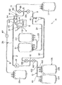
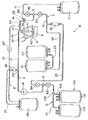
図1は、本発明の血液成分分離装置の第1実施例を示す平面図、図2は、図1に示す血液成分分離装置の制御系を示すブロック図である。これらの図に示すように、血液成分分離装置1Aは、遠心ボウル(遠心分離器)4と、その回転駆動装置5と、遠心ボウル4に血液および血漿を選択的に導入する第1のライン2(血液または血漿導入ライン)と、遠心ボウル4にて分離された血液成分を回収する第2のライン3(血液成分回収ライン)と、バフィーコートを貯留する容器であるバフィーコートバッグ25と、該バフィーコートバッグ25内のバフィーコートを遠心ボウル4へ導入する第3のライン8と、光学センサー61、62と、制御手段7と、血液貯留部106を有する第4のライン(供血者を想定した脱・返血ライン)10と、第1のライン2に設置されたポンプ91とを有する。
FIG. 1 is a plan view showing a first embodiment of the blood component separation apparatus of the present invention, and FIG. 2 is a block diagram showing a control system of the blood component separation apparatus shown in FIG. As shown in these drawings, the blood component separation device 1A includes a centrifugal bowl (centrifugal separator) 4, a
図1に示すように、第4のライン10は、主に、チューブ101と、チューブ101の途中にト字状の分岐コネクタ102を介して接続されたチューブ103と、チューブ101、103の先端にそれぞれ接続された血液バッグ104、105とで構成されている。両血液バッグ104、105により、血液貯留部106が構成されている。
As shown in FIG. 1, the
チューブ101の基端は、T字状の分岐コネクタ12を介してチューブ13および20の一端と接続されている。チューブ101の途中には、チューブ101の内部流路を遮断・解放し得る流路開閉手段であるバルブ83が設置されている。
The base end of the
第1のライン2は、チューブ13およびその一端に接続された分岐コネクタ12により構成されている。チューブ13の他端は、遠心ボウル4の流入口43に接続され、チューブ13の途中には、例えばローラポンプよりなる送液用のポンプ91が設置されている。
The
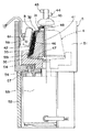
図3に示すように、遠心ボウル4は、上端に流入口43が形成された鉛直方向に伸びる管体41と、該管体41の回りで回転し、上部45に対し液密にシールされたローター42とで構成されている。ローター42の内部には、ローター周壁内面に沿って環状の貯血空間46が形成されている。この貯血空間46は、図3中下部から上部に向けてその内外径が漸減するような形状(テーパ状)をなしている。貯血空間46の下部は、ローター42の底部に沿って形成されたほぼ円盤状の流路47を介して管体41の下端開口と連通し、貯血空間46の上部は、流路48を介して流出口44に連通している。また、このローター42において、貯血空間46の容積は、例えば、100〜350ml程度とされる。
As shown in FIG. 3, the
このようなローター42は、回転駆動装置5により予め設定された所定の遠心条件(回転速度および回転時間)で回転される。この遠心条件により、ローター42内の血液の分離パターン(例えば、分離する血液成分数)を設定することができる。本実施例では、図3に示すように、血液が貯血空間46内で内層より血漿層31、バフィーコート層32および赤血球層33に分離されるように遠心条件が設定される。
Such a
回転駆動装置5は、図3に示すように、遠心ボウル4を収納するハウジング51と、脚部52と、駆動源であるモータ53と、遠心ボウル4を保持する円盤状の固定台55とで構成されている。
As shown in FIG. 3, the
ハウジング51は、脚部52の上部に載置、固定されている。また、ハウジング51の下面には、ボルト56によりスペーサー57を介してモータ53が固定されている。モータ53の回転軸54の先端部には、固定台55が回転軸54と同軸でかつ一体的に回転するように嵌入されており、固定台55の上部には、ローター42の底部が嵌合する凹部551が形成されている。また、遠心ボウル4の上部45は、図示しない固定部材によりハウジング51に固定されている。
The
このような回転駆動装置5では、モータ53を駆動すると、固定台55およびそれに固定されたローター42が、例えば、回転数3000〜6000rpm で回転する。
In such a
ハウジング51の内壁には、ローター42内の分離された血液成分の界面、すなわち、バフィーコート層32と赤血球(濃厚赤血球)層33との界面Bの位置を光学的に検出する光学センサー61が、取付部材58により設置、固定されている。この光学センサー61としては、ローター42の外周面に沿って上下方向に走査し得るラインセンサーが用いられる。すなわち、LEDのような発光素子とフォトダイオードのような受光素子とが列状に配置され、発光素子から発っせられた光の血液成分での反射光を受光素子により受光し、その受光光量を光電変換するように構成されている。分離されたバフィーコート層32と赤血球層33とで反射光の強度が異なるため、受光光量すなわち出力電圧が変化した受光素子に対応する位置が、界面Bの位置として検出される。
On the inner wall of the
図1に示すように、遠心ボウル4の流出口44には、チューブ14の一端が接続され、チューブ14の他端は、T字状の分岐コネクタ15を介してチューブ16および18の一端と接続されている。
As shown in FIG. 1, one end of the
チューブ16の他端は、血小板バッグ17に接続され、チューブ16の途中には、チューブ16内の流路を開閉するバルブ85が設置されている。
また、チューブ18の他端は、気泡除去用のチャンバー19に接続され、チューブ18の途中には、チューブ18内の流路を開閉するバルブ86が設置されている。
The other end of the
The other end of the
一端が分岐コネクタ12に接続されているチューブ20の他端は、気泡除去用のチャンバー19に接続され、チューブ20の途中には、チューブ20内の流路を開閉するバルブ84が設置されている。
The other end of the
空気貯留バッグ22は、一連の処理後に血漿バッグ21内からエアーを排出し、これを貯留するためのバッグであり、そのため、血漿バッグ21および空気貯留バッグ22は、チューブ23により接続されてその内部同士が連通している。また、血漿バッグ21には、チューブ24の一端が接続され、チューブ24の他端は、気泡除去用のチャンバー19に接続されている。
The
このような構成において、チューブ14、16、18、20、23、24、分岐コネクタ15、チャンバー19およびバッグ17、21、22により、第2のライン3が構成されている。このうち、チューブ18、チャンバー19、チューブ23、24およびバッグ21、22は、血漿を回収するための血漿回収用分岐ラインを構成し、チューブ14、16および血小板バッグ17は、血小板を回収するための血小板回収用分岐ラインを構成する。
In such a configuration, the
なお、図示されていないが、血漿バッグ21は、チューブ24の接続側端部を上方または下方へ選択的に向けることができる装置(バッグ揺動装置)にセットされていてもよい。
Although not shown, the
チューブ14の流出口44の近傍には、分岐コネクタ28が設置され、この分岐コネクタ28には、チューブ26の一端が接続されている。また、チューブ26の他端は、バフィーコートバッグ25に接続され、チューブ26の途中には、チューブ26内の流路を開閉するバルブ87が設置されている。このチューブ26および分岐コネクタ28により第3のライン8が構成されている。
A
このようなバフィーコートバッグ25は、複数個設置されていてもよく、その接続パターンも特に限定されない。また、バフィーコートバッグ25の容量は、特に限定されないが、通常、合計容量が100〜800ml程度が好ましく、400〜500ml程度がより好ましい。
なお、図示されていないが、バフィーコートバッグ25は、前記と同様のバッグ揺動装置にセットされていてもよい。
A plurality of such
Although not shown, the
また、チューブ14の途中には、チューブ14内を流れる血液成分中の血小板の濃度を検出し得る光学センサー62が設置されている。この光学センサー62は、チューブ14を介して対向配置された投光部(光源)63および受光部(フォトダイオード)64で構成されている。投光部63から発せられた光(例えばレーザー光)は、チューブ14を透過して受光部64で受光され、その受光光量に応じた電気信号に変換されるが、チューブ14内を流れる血液成分中の血小板濃度に応じて透過率が変化し、受光部64での受光光量が変動するため、この変動を受光部64からの出力電圧の変化として検出することができる。
Further, an
前記各バルブ83〜87は、例えば、ソレノイド、電動モーター、またはシリンダ(油圧または空気圧)等の駆動源で作動し、該駆動源は、後述する制御手段7からの信号に基づいて作動する。なお、本発明において、流路開閉手段は、前記バルブ(コック)に限らず、例えば可撓性チューブを挟持してその内腔を閉塞し得るクレンメであってもよい。
Each of the
前記各バッグ17、21、22、25、104、105は、それぞれ、樹脂製の可撓性を有するシート材を重ね、その周縁部を融着(熱融着、高周波融着等)または接着して袋状にしたものである。
Each of the
各バッグ17、21、22、25、104、105を構成するシート材の構成材料としては、例えば、軟質ポリ塩化ビニルが好適に使用される。この軟質ポリ塩化ビニルにおける可塑剤としては、例えば、ジ(エチルヘキシル)フタレート(DEHP)、ジ−(n−デシル)フタレート(DnDP)等が使用される。なお、このような可塑剤の含有量は、ポリ塩化ビニル100重量部に対し、30〜70重量部程度とするのが好ましい。
For example, soft polyvinyl chloride is preferably used as a constituent material of the sheet material constituting each of the
また、各バッグ17、21、22、25、104、105のシート材の他の構成材料としては、ポリオレフィン、すなわちエチレン、プロピレン、ブタジエン、イソプレン等のオレフィンあるいはジオレフィンを重合または共重合した重合体を用いることができ、例えば、ポリエチレン、ポリプロピレン、エチレン−酢酸ビニル共重合体(EVA)、EVAと各種熱可塑性エラストマーとのポリマーブレンド等、あるいは、これらを任意に組み合せたものが挙げられる。さらには、ポリエチレンテレフタレート(PET)、ポリブチレンテレフタレート(PBT)、ポリ−1,4−シクロヘキサンジメチルテレフタレート(PCHT)のようなポリエステルや、ポリ塩化ビニリデンを用いることもできる。
Further, as another constituent material of the sheet material of each
なお、血小板バッグ17を構成するシート材は、血小板保存性を向上するために、ガス透過性に優れるものが好ましく、そのために、例えば、シート材として、前記ポリオレフィンやDnDP可塑化ポリ塩化ビニル等を用いたり、また、シート材の厚さを比較的薄く(例えば、0.1〜0.5mm程度、特に、0.1〜0.3mm程度)するのが好ましい。
In addition, the sheet material constituting the
血液バッグ104、105の少なくとも一方の内部には、予め血液が貯留されている。この血液中には、例えば、ACD−A液、CPD液、CPD−A1液、ヘパリンナトリウム液等の抗凝固剤が添加されているのが好ましい。なお、血液貯留部106に設置される血液バッグの数は、1または3以上であってもよく、その接続方法、接続パターンも任意可能である。例えば、実開平6−26877号公報等に記載されているチューブ接続装置により、1または2以上の血液バッグを無菌的に接続、交換して使用することもできる。
また、血小板バッグ17は、空の状態でもよいが、例えば、生理食塩水、GAC、PAS、PSM−1のような血小板保存液が予め入れられていてもよい。
Blood is stored in advance in at least one of the
Moreover, although the
チューブ101、103、13、14、16、18、20、23、24、26、27の構成材料としては、例えば、ポリ塩化ビニル、ポリエチレン、ポリプロピレン、PETやPBTのようなポリエステル、エチレン−酢酸ビニル共重合体、ポリウレタン、ポリエステルエラストマー、スチレン−ブタジエン−スチレン共重合体等の熱可塑性エラストマー等が挙げられるが、その中でも特に、ポリ塩化ビニルが好ましい。各チューブがポリ塩化ビニル製であれば、十分な可撓性、柔軟性が得られるので取り扱いがし易く、また、クレンメ等による閉塞にも適するからである。
また、分岐コネクタ102、12、15、28、29の構成材料についても、前記チューブの構成材料と同様のものを用いることができる。
The constituent materials of the
Further, the constituent materials of the
図2に示すように、血液成分分離装置1Aは、例えばマイクロコンピュータで構成される制御手段7を有し、該制御手段7には、前記ポンプ91、バルブ83〜87、光学センサー61、62および回転駆動装置5がそれぞれ電気的に接続されている。
As shown in FIG. 2, the blood component separation apparatus 1A has a control means 7 composed of, for example, a microcomputer. The control means 7 includes the
光学センサー61からの検出信号(界面位置検出情報)および光学センサー62からの検出信号(血小板濃度情報)は、それぞれ、制御手段7へ随時入力される。制御手段7は、光学センサー61、62からの各検出信号に基づき、ポンプ91の回転/停止、回転方向(正転/逆転)および回転数を制御するとともに、必要に応じ、各バルブ83〜87の開閉および回転駆動装置5の作動を制御する。
A detection signal (interface position detection information) from the
以上のような遠心ボウル4を用いた血液成分分離装置1Aでは、バッグ内で血液を遠心分離する方法に比べ、回収された血小板のペレット化(塊状となること)が極めて少ないという利点がある。
The blood component separation apparatus 1A using the
次に、図1に示す血液成分分離装置1Aを用いた血小板採取方法の好適な実施例について説明する。以下の各工程におけるバルブ83〜87、ローター42およびポンプ91の作動状態を、下記表1に示し、該表1を参照しつつ説明する。
Next, a preferred embodiment of a platelet collection method using the blood component separation device 1A shown in FIG. 1 will be described. The operating states of the

[1a] 血液バッグ104、105内には、それぞれ、例えば400mlの採血血液が充填されており、チューブ103をクレンメで閉塞し、バルブ開閉パターンを表1中の(1)として、ポンプ91を作動(正転)する。これにより、血液バッグ104内の血液は、チューブ101および13を介して移送され、遠心ボウル4の流入口43より管体41を経てローター42内に導入される。なお、ポンプ91の回転速度は、血液吐出量(血液供給速度)が例えば30〜80ml/min 程度となるように設定される。
[1a] Each of the
[2a] また、前記工程[1a]の血液移送と同時に、回転駆動装置5を作動して、ローター42を好ましくは3000〜6000rpm (例えば、4800rpm )で回転する。管体41の下端開口より流出した血液は、ローター42の回転による遠心力により、流路47を外周方向へ向けて放射状に流れ、貯血空間46に集められ、該貯血空間46において内層より血漿層31、バフィーコート層32および赤血球層33に分離される。
[2a] Further, simultaneously with the blood transfer in the step [1a], the
[3a] 前記工程[1a]、[2a]を継続しつつ、血漿層31が貯血空間46の上部に到達したら、バルブ開閉パターンを(2)とする。これにより、ローター42内の血漿が流出口44よりオーバーフローし、チューブ14、18、チャンバー19、チューブ24を介して血漿バッグ21内に回収される。
[3a] When the
[4a] ローター42内からの血漿の排出に伴い、バフィーコート層32と赤血球層33との界面Bも徐々に上昇する。この界面Bは、光学センサー61により随時検出されており、界面Bが所定レベル、すなわち流出口44からバフィーコートが流出し始める程度のレベルに到達したことが検出されると、制御手段7は、その検出信号(界面位置検出情報)に基づき、バルブ開閉パターンを(3)とするよう制御する。これにより、以後、流出口44から流出したバフィーコートは、チューブ14、26を介してバフィーコートバッグ25へ移送、回収される。
[4a] As the plasma is discharged from the
[5a] 光学センサー61により、界面Bが所定レベル、すなわち貯血空間46からほぼ全てのバフィーコートが排出される程度のレベルに到達したことが検出されると、制御手段7は、その検出信号(界面位置検出情報)に基づき、回転駆動装置5を停止し、バルブ開閉パターンを(4)とし、ポンプ91を逆回転するよう制御する。これにより、遠心ボウル4内に残った赤血球が、管体41、チューブ13、101を介して、血液バッグ104内に返血される。
[5a] When the
[6a] バルブ開閉パターンを(5)とし、ポンプ91を作動(正転)して、血漿バッグ21内の血漿の全部または一部をチューブ24、チャンバー19、チューブ20、13を介してローター42内に入れる。
[6a] The valve opening / closing pattern is set to (5), the
[7a] 続いて、バルブ開閉パターンを(6)とし、ポンプ91を逆回転して、血漿バッグ21から移送した遠心ボウル4内の血漿を、管体41、チューブ13、101を介して、血液バッグ104内に返血する。
[7a] Subsequently, the valve opening / closing pattern is set to (6), the
[8a] 分岐コネクタ102と血液バッグ104との間のチューブ101の途中を例えば融着により封止し、さらにこの封止部を切断、分離する。これにより、返血用乏血小板血液入りの血液バッグ104が得られる。血液バッグ104内の乏血小板血液は、必要に応じ、供血者に返血される。
[8a] The middle of the
なお、処理する血液バッグ数がn個(n=3以上の整数)である場合、n−1個までの血液バッグに対し、前記工程[1a]〜[8a]を繰り返し行い、n個目の血液バッグに対し、以下の工程を行う。 When the number of blood bags to be processed is n (n = an integer greater than or equal to 3), the above steps [1a] to [8a] are repeated for up to n−1 blood bags, The following steps are performed on the blood bag.
[9a] 回転駆動装置5を作動してローター42を例えば3000〜6000rpmで回転するとともに、バフィーコートバッグ25のチューブ26の接続側端部を下方へ向けた状態で、バルブ開閉パターンを(7)とし、ポンプ91を逆回転する。これにより、バフィーコートバッグ25内に貯留されているバフィーコートは、チューブ26、14、流出口44、流路48を介して貯血空間46内に戻される。
[9a] The
[10a] クレンメによるチューブ103の閉塞を解除し、バルブ開閉パターンを(8)とし、ポンプ91を前記工程[1a]と同条件で作動(正転)する。これにより、血液バッグ105内の血液は、チューブ103、101および13を介して移送され、遠心ボウル4の流入口43より管体41を経てローター42内に導入され、貯血空間46において血液が内層より血漿層31、バフィーコート層32および赤血球層33に分離される。
[10a] The blockage of the
この場合、バフィーコート層32は、複数回の採血に相当する複数の血液バッグ(図示の構成では血液バッグ104、105)内の合計の血液より得られる量のバフィーコートで構成されるため、その層厚が厚くなり、後述するサージ工程において、血小板の浮上、濃縮がより明確に行われ、血小板の収率および回収された血小板中の白血球の除去率が向上する。
In this case, the buffy coat layer 32 is composed of a buffy coat in an amount obtained from the total blood in a plurality of blood bags (
[11a] 流出口44より血漿が流出したら、まず、バルブ開閉パターンを(9)とする。これにより、流出口44より流出した血漿が、チューブ14、26を介してバフィーコートバッグ25内に導入され、チューブ14、26の流路およびバフィーコートバッグ25の内部が洗浄される。このとき、バフィーコートバッグ25を揺動させると、その内部の洗浄効果が高まり、好ましい。
[11a] When plasma flows out from the
[12a] バフィーコートバッグ25のチューブ26の接続側端部を下方へ向けた状態で、バルブ開閉パターンを(10)とし、ポンプ91を逆回転する。これにより、バフィーコートバッグ25内等の洗浄に供された血漿(洗浄液)が、チューブ26、14、流出口44、流路48を介して貯血空間46内に戻される。なお、バフィーコートバッグ25を高所へ置き、必要に応じ所定のエアー抜きを設け、落差によりバフィーコートバッグ25内の洗浄液を貯血空間46へ移送してもよく、あるいは、バフィーコートバッグ25を例えば一対の加圧板等により挟持、圧迫して洗浄液を排出、移送してもよい。
[12a] With the connection side end of the
このような、バフィーコートバッグ25内等の洗浄およびその洗浄液の貯血空間46への回収を行うことにより、血小板をバフィーコートバッグ25内等に残存せず、血小板の収率が向上する。
By washing the inside of the
[13a] バルブ開閉パターンを(11)とし、ポンプ91を作動(正転)する。これにより、血漿バッグ21内の血漿が、チューブ24、チャンバー19、チューブ20、13および管体41を介してローター42内に供給され、さらにチューブ14、16を流れ、サージ回路が血漿でプライミングされる。
[13a] The valve opening / closing pattern is (11), and the
[14a] 次いで、バルブ開閉パターンを(12)とする。これにより、ローター42内の血漿が流出口44より流出し、チューブ14、18、チャンバー19、チューブ24を介して血漿バッグ21内に回収される。
[14a] Next, the valve opening / closing pattern is (12). As a result, the plasma in the
[15a] 光学センサー61により、界面Bが所定のサージ開始レベル、すなわち貯血空間46の容積に対する貯血空間46内に存在する赤血球層33の体積の比率が好ましくは70〜96%、より好ましくは85〜94%に達したときのレベルに到達したことが検出されると、制御手段7は、その検出信号(界面位置検出情報)に基づき、バルブ開閉パターンを(13)とするよう制御する。これにより、血漿バッグ21内の血漿が、チューブ24、チャンバー19、チューブ20、13および管体41を介してローター42内に供給される。管体41の下端開口より流出した血漿は、ローター42の回転による遠心力により、流路47を外周方向へ向けて放射状に流れ、貯血空間46の下部を経て貯血空間46内を上昇する。これにより、バフィーコート層32中の血小板が遠心力に抗して浮上し(舞い上がり)、流路48を経て流出口44より流出し、チューブ14および16を介して血小板バッグ17内に回収される(サージ工程)。なお、血小板の流出は、光学センサー62による血小板濃度の上昇により検知される。
[15a] By the
このサージ工程において、制御手段7は、ポンプ91の回転速度(血漿吐出量)を制御することにより、ローター42内への血漿の供給速度を好ましくは10〜90ml/min、より好ましくは10〜70ml/minに設定する。血漿供給速度が10ml/min未満では、血小板の回収に長時間を要し、90ml/minを超えると、血小板とともに白血球の浮上量が増え、回収された血小板中の白血球の除去率が低下するからである。
In this surge process, the control means 7 controls the rotational speed (plasma discharge amount) of the
また、血小板の回収中において、血漿の供給速度は、10〜90ml/minの範囲内で適宜変更してもよい。例えば、最初に血漿を所定速度で供給し、次いでそれより低速で供給するサイクルを少なくとも1回行うような方法が挙げられる。このような場合、血漿の最大供給速度は、25〜90ml/min、特に30〜70ml/minとするのが好ましい。このような血漿供給速度の変更は、例えば、制御手段7に内蔵されるタイマーに基づいて、あるいは光学センサー62により検出される血小板濃度情報に応じて行うことができる。
Further, during the collection of platelets, the plasma supply rate may be appropriately changed within the range of 10 to 90 ml / min. For example, there is a method in which plasma is first supplied at a predetermined rate and then supplied at a lower rate at least once. In such a case, the maximum plasma supply rate is preferably 25 to 90 ml / min, particularly 30 to 70 ml / min. Such a change in the plasma supply rate can be performed based on, for example, a timer built in the
[16a] 光学センサー62により検出される血小板濃度が予め設定された基準値以下となったら、血小板バッグ17への血小板の回収が終了したものとみなし、制御手段7は、その検出信号(血小板濃度情報)に基づき、回転駆動装置5を停止し、バルブ開閉パターンを(14)とし、ポンプ91を逆回転するよう制御する。これにより、遠心ボウル4内に残った赤血球、白血球および血漿が、管体41、チューブ13、101を介して、血液バッグ105内に返血される。
[16a] When the platelet concentration detected by the
[17a] バルブ開閉パターンを(15)とし、ポンプ91を作動(正転)して、血漿バッグ21内に残った血漿をチューブ24、チャンバー19、チューブ20、13を介してローター42内に入れる。
[17a] The valve opening / closing pattern is set to (15), the
[18a] 続いて、バルブ開閉パターンを(16)とし、ポンプ91を逆回転して、血漿バッグ21から移送した遠心ボウル4内の血漿を、管体41、チューブ13、101を介して、血液バッグ105内に返血する。
[18a] Subsequently, the valve opening / closing pattern is set to (16), the
[19a] チューブ103の途中を例えば融着により封止し、さらにこの封止部を切断、分離する。これにより、返血用乏血小板血液入りの血液バッグ105が得られる。血液バッグ105内の乏血小板血液は、必要に応じ、供血者に返血される。
[19a] The middle of the
[20a] 血小板バッグ17付近のチューブ16を例えば融着により封止し、さらにこの封止部を切断、分離することにより、血小板製剤入りの血小板バッグ17が得られる。
[20a] The
以上のように、本発明では、複数の血液バッグ(図示の構成では血液バッグ104、105)内の合計の血液より得られる量のバフィーコートを集め、これに対し一度にサージ工程を行うため、サージの際の貯血空間46内におけるバフィーコート層32の層厚が厚くなり、よって、バフィーコート層32中からの血小板の浮上、濃縮がより明確に行われ、血小板の収率および回収された血小板中の白血球の除去率が向上する。
As described above, in the present invention, a buffy coat of an amount obtained from the total blood in a plurality of blood bags (
特に、サージ工程において、血漿の供給速度を10〜90ml/minとすることにより、血小板の浮上を最適に調整し、よって、白血球の除去率が極めて高い高品質の血小板製剤が得られる。しかも、光学センサー61により、分離された血液成分の界面を検出し、それに基づいて血漿供給の開始(血液供給の終了)のタイミングを制御するため、自動化とともにより高精度の制御が可能となり、血小板の回収率および回収された血小板中の白血球の除去率がさらに向上する。このようなことから、該血小板製剤を用いた場合、肝炎、エイズ、GVHD等の感染をより高い確率で防止することができ、安全性が高い。
また、サージ工程が1回でよいため、全体の処理時間を短縮することができる。
In particular, in the surge process, by setting the plasma supply rate to 10 to 90 ml / min, the floating of platelets is optimally adjusted, and thus a high-quality platelet preparation with an extremely high leukocyte removal rate can be obtained. In addition, since the interface of the separated blood component is detected by the
Further, since only one surge process is required, the entire processing time can be shortened.
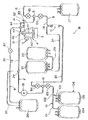
図4は、本発明の血液成分分離装置の第2実施例の構成を模式的に示す平面図である。同図に示す血液成分分離装置1Bは、第3のライン8の構成が異なる以外は、前記血液成分分離装置1Aと同様である。
FIG. 4 is a plan view schematically showing the configuration of the second embodiment of the blood component separation device of the present invention. The blood component separation device 1B shown in the figure is the same as the blood component separation device 1A except that the configuration of the
血液成分分離装置1Bにおいて、バフィーコートバッグ25には、2本のチューブ(第2チューブ)26およびチューブ(第1チューブ)27の一端がそれぞれ接続されている。チューブ26の他端は、前記と同様、分岐コネクタ28を介してチューブ14の途中に接続されており、チューブ27の他端は、分岐コネクタ29を介してチューブ13のポンプ91と流入口43との間に接続されている。また、チューブ26の途中には、チューブ26内の流路を開閉するバルブ87が設置されている。これらのチューブ26、27および分岐コネクタ28、29により第3のラインが構成されている。
In the blood component separation device 1B, the
このような血液成分分離装置1Bを用いた血小板採取方法は、次の通りであり、工程[12a]以外は、基本的に前記血液成分分離装置1Aによる血小板採取方法と同様である。 The platelet collection method using such a blood component separation apparatus 1B is as follows, and is basically the same as the platelet collection method by the blood component separation apparatus 1A except for the step [12a].
[1b]〜[11b] チューブ27をクレンメで閉塞した状態で、前記[1a]〜[11a]と同様の工程を行う。
[1b] to [11b] The same steps as [1a] to [11a] are performed in a state where the
[12b] ポンプ91の作動(正転)下で、バルブ83および86を開放、その他のバルブを閉鎖した状態とする。さらに、チューブ27のクレンメによる閉塞を解除し、バフィーコートバッグ25を高所へ置き、かつそのチューブ26の接続側端部を下方へ向け、落差によりバフィーコートバッグ25内の洗浄液(血漿)をチューブ27を介して第1のライン2へ供給する。これにより、洗浄液は、分岐コネクタ29内において、ポンプ91より送液されて来る血液と混合され、チューブ13、流入口43および管体41を介して貯血空間46へ移送される。
[12b] Under the operation (forward rotation) of the
[13b]〜[20b] チューブ27をクレンメで再び閉塞した状態で、前記[13a]〜[20a]と同様の工程を行う。
[13b] to [20b] Steps similar to [13a] to [20a] are performed in a state where the
このような血小板採取方法では、工程[12b]における洗浄液(血小板を含む)の返送を、血液貯留部106からローター42内への血液の移送を停止することなく行うことができるので、全体の処理時間を短縮することができるという利点がある。
In such a platelet collection method, the cleaning liquid (including platelets) in step [12b] can be returned without stopping the transfer of blood from the
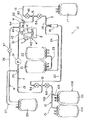
図5は、本発明の血液成分分離装置の第3実施例の構成を模式的に示す平面図である。同図に示す血液成分分離装置1Cは、ポンプ91の位置が異なる以外は、前記血液成分分離装置1Bと同様である。
FIG. 5 is a plan view schematically showing the configuration of the third embodiment of the blood component separation device of the present invention. The blood
すなわち、血液成分分離装置1Cにおいて、ポンプ91は、チューブ13の分岐コネクタ29と流入口43との間に設置されている。
このような血液成分分離装置1Cを用いた血小板採取方法は、次の通りである。各工程におけるバルブ83〜87、ローター42およびポンプ91の作動状態を、下記表2に示し、該表2を参照しつつ説明する。
That is, in the blood
A platelet collection method using such a blood
[1c]〜[8c] チューブ27をクレンメで閉塞した状態で、前記[1a]〜[8a]と同様の工程を行う。
[1c] to [8c] The same steps as [1a] to [8a] are performed with the
[9c] 回転駆動装置5を作動してローター42を所定の回転数で回転するとともに、クレンメによるチューブ103の閉塞を解除し、バルブ開閉パターンを表2中の(8)とし、ポンプ91を前記工程[1a]と同条件で作動(正転)する。これにより、血液バッグ105内の血液は、チューブ103、101および13を介して移送され、遠心ボウル4の流入口43より管体41を経てローター42内に導入され、貯血空間46において血液が内層より血漿層31、バフィーコート層32および赤血球層33に分離される。
[9c] The
[10c] 前記工程[9c]と同時に、バフィーコートバッグ25のチューブ26の接続側端部を下方へ向けた状態で、チューブ27のクレンメによる閉塞を解除する。これにより、バフィーコートバッグ25内に貯留されているバフィーコートは、ポンプ91の作動によりチューブ27を介して第1のライン2へ供給され、分岐コネクタ29内において、血液貯留部106側から送液されて来る血液と混合され、チューブ13、流入口43および管体41を介して貯血空間46へ移送され、遠心分離に供される。バフィーコートバッグ25からバフィーコートのほぼ全量が排出されたら、再びチューブ27をクレンメで閉塞する。
[10c] Simultaneously with the step [9c], the clogging of the
貯血空間46においては、血液バッグ105からの血液とバフィーコートバッグ25からのバフィーコートとが混合され、遠心分離が施されるが、分離されたバフィーコート層32は、複数回の採血に相当する複数の血液バッグ(図示の構成では血液バッグ104、105)内の合計の血液より得られる量のバフィーコートで構成されるため、その層厚が厚くなり、サージ工程において、血小板の浮上、濃縮がより明確に行われ、血小板の収率および回収された血小板中の白血球の除去率が向上する。
In the
[11c] 流出口44より血漿が流出したら、バルブ開閉パターンを(9)とする。これにより、流出口44より流出した血漿が、チューブ14、26を介してバフィーコートバッグ25内に導入され、チューブ14、26の流路およびバフィーコートバッグ25の内部が洗浄される。このとき、バフィーコートバッグ25を揺動させると、その内部の洗浄効果が高まり、好ましい。
[11c] When plasma flows out from the
[12c] バフィーコートバッグ25のチューブ26の接続側端部を下方へ向けた状態で、バルブ開閉パターンを(10)とし、再びクレンメによるチューブ27の閉塞を解除する。これにより、バフィーコートバッグ25内等の洗浄に供された血漿(洗浄液)が、前記工程[10c]と同様の経路で貯血空間46内に戻される。
[12c] With the connection side end of the
このような、バフィーコートバッグ25内等の洗浄およびその洗浄液の貯血空間46への回収を行うことにより、血小板をバフィーコートバッグ25内等に残存せず、血小板の収率が向上する。
By washing the inside of the
[13c]〜[20c] チューブ27をクレンメで再び閉塞した状態で、前記[13a]〜[20a]と同様の工程を行う。
[13c] to [20c] The same steps as [13a] to [20a] are performed in a state where the
このような血小板採取方法では、工程[10c]におけるバフィーコートの返送および工程[12c]における洗浄液(血小板を含む)の返送を、血液貯留部106からローター42内への血液の移送中に行うことができ、特に、バフィーコートおよび洗浄液の返送をポンプ91の駆動により確実かつ迅速に行うことができるので、全体の処理時間をさらに短縮することができる。
In such a platelet collection method, the buffy coat is returned in step [10c] and the cleaning liquid (including platelets) is returned in step [12c] during the transfer of blood from
図6は、本発明の血液成分分離装置の第4実施例の構成を模式的に示す平面図である。同図に示す血液成分分離装置1Dは、チューブ27の途中にポンプ92を設置した以外は、前記血液成分分離装置1Bと同様である。ポンプ92としては、例えばローラポンプが用いられ、図2中の制御手段7によりその駆動が制御される。このポンプ92は、一方向のみ回転可能なものであればよい。この構成では、ポンプ92が停止しているときには、チューブ27の流路は、閉塞されているが、チューブ27の途中に別途前記と同様のバルブ(図示せず)を設けてもよい。
FIG. 6 is a plan view schematically showing the configuration of the fourth embodiment of the blood component separation device of the present invention. The blood component separation apparatus 1D shown in the figure is the same as the blood component separation apparatus 1B except that a
このような血液成分分離装置1Dを用いた血小板採取方法は、次の通りである。各工程におけるバルブ83〜87、ローター42およびポンプ91、92の作動状態を、下記表3に示し、該表3を参照しつつ説明する。
The platelet collection method using such a blood component separation device 1D is as follows. The operating states of the
[1d]〜[8d] ポンプ92を停止した状態で、前記[1a]〜[8a]と同様の工程を行う。
[1d] to [8d] The same steps as [1a] to [8a] are performed with the
[9d] 回転駆動装置5を作動してローター42を所定の回転数で回転するとともに、クレンメによるチューブ103の閉塞を解除し、バルブ開閉パターンを表3中の(8)とし、ポンプ91を前記工程[1a]と同条件で作動(正転)する。これにより、血液バッグ105内の血液は、チューブ103、101および13を介して移送され、遠心ボウル4の流入口43より管体41を経てローター42内に導入され、貯血空間46において血液が内層より血漿層31、バフィーコート層32および赤血球層33に分離される。
[9d] The
[10d] 前記工程[9d]と同時に、バフィーコートバッグ25のチューブ26の接続側端部を下方へ向けた状態で、ポンプ92を作動(正転)する。これにより、バフィーコートバッグ25内に貯留されているバフィーコートは、チューブ27を介して第1のライン2へ供給され、分岐コネクタ29内において、血液貯留部106側から送液されて来る血液と混合され、チューブ13、流入口43および管体41を介して貯血空間46へ移送され、遠心分離に供される。バフィーコートバッグ25からバフィーコートのほぼ全量が排出されたら、ポンプ92を停止する。
[10d] Simultaneously with the step [9d], the
[11d] 流出口44より血漿が流出したら、まず、バルブ開閉パターンを(9)とする。これにより、流出口44より流出した血漿が、チューブ14、26を介してバフィーコートバッグ25内に導入され、チューブ14、26の流路およびバフィーコートバッグ25の内部が洗浄される。このとき、バフィーコートバッグ25を揺動させると、その内部の洗浄効果が高まり、好ましい。
[11d] When plasma flows out from the
[12d] バフィーコートバッグ25のチューブ26の接続側端部を下方へ向けた状態で、バルブ開閉パターンを(10)とし、ポンプ92を作動(正転)する。これにより、バフィーコートバッグ25内等の洗浄に供された血漿(洗浄液)が、前記工程[10d]と同様の経路で貯血空間46内に戻される。このような操作により、前記と同様、血小板が回路に残存せず、その収率が向上する。
[12d] With the connection side end of the
[13d]〜[20d] ポンプ92を停止した状態で、前記[13a]〜[20a]と同様の工程を行う。
[13d] to [20d] Steps similar to [13a] to [20a] are performed with the
このような血小板採取方法では、工程[10d]におけるバフィーコートの返送および工程[12d]における洗浄液(血小板を含む)の返送を、血液貯留部106からローター42内への血液の移送中に行うことができ、特に、バフィーコートおよび洗浄液の返送をポンプ92の駆動により確実かつ迅速に行うことができるので、全体の処理時間をさらに短縮することができる。
In such a platelet collecting method, the buffy coat is returned in step [10d] and the cleaning liquid (including platelets) is returned in step [12d] during the transfer of blood from
なお、血液成分分離装置1Dにおいて、チューブ20の一端を分岐コネクタ12と接続せず、図示しない分岐コネクタを用いてチューブ27の途中に接続した構成としてもよい。
In blood component separation device 1D, one end of
次に、本発明を具体的実施例に基づいてさらに詳細に説明する。
(実施例1)
図1および図2に示す構成の血液成分分離装置1Aを用い、前述した工程[1a]〜[20a]により、貯血量400mlの血液バッグ5個に対し血液処理を行い、血小板製剤の作製を行った。各工程での条件を下記表4に示す。
Next, the present invention will be described in more detail based on specific examples.
(Example 1)
Using the blood component separation apparatus 1A having the configuration shown in FIGS. 1 and 2, blood processing is performed on five blood bags with a blood storage volume of 400 ml by the steps [1a] to [20a] described above to produce a platelet preparation. It was. The conditions in each step are shown in Table 4 below.
(実施例2)
図5および図2に示す構成の血液成分分離装置1Cを用い、前述した工程[1c]〜[20c]により、貯血量400mlの血液バッグ5個に対し血液処理を行い、血小板製剤の作製を行った。対応する各工程での条件は、上記表4に示す条件と同様とした。
(Example 2)
Using the blood
(実施例3)
図6および図2に示す構成(ただし、ポンプ92は制御手段7に接続)の血液成分分離装置1Dを用い、前述した工程[1d]〜[20d]により、貯血量400mlの血液バッグ5個に対し血液処理を行い、血小板製剤の作製を行った。対応する各工程での条件を上記表5に示す条件と同様とした。
(Example 3)
Using the blood component separation device 1D having the configuration shown in FIGS. 6 and 2 (however, the
(比較例)
図1に示す装置において、バフィーコートバッグ25および第3のライン8を有さない構成の回路を用い、貯血量400mlの血液バッグ5個のそれぞれを処理する毎に、サージ工程を行い、サージ5回分の血小板を集め血小板製剤とした。
なお、各サージ工程における血漿供給は、ポンプ吐出量(血漿供給速度)220ml/minで40秒とした。
(Comparative example)
In the apparatus shown in FIG. 1, a surge process is performed each time five blood bags each having a blood storage volume of 400 ml are processed using a circuit having no
The plasma supply in each surge process was 40 seconds at a pump discharge rate (plasma supply speed) of 220 ml / min.
[評価]
実施例1〜3および比較例で得られた血小板製剤について、回収量、血小板数、白血球数、血小板回収率および処理時間を求めた。その結果を下記表6に示す。なお、血小板数は、血球計数装置(東亜電子社製、Sysmex K-2000型)を用いてカウントし、白血球数は、Negeotteチャンバー法により測定した。
[Evaluation]
With respect to the platelet preparations obtained in Examples 1 to 3 and the comparative example, the recovery amount, the platelet count, the white blood cell count, the platelet recovery rate and the treatment time were determined. The results are shown in Table 6 below. The platelet count was counted using a blood cell counter (manufactured by Toa Electronics Co., Ltd., Sysmex K-2000 type), and the white blood cell count was measured by the Negeotte chamber method.
上記表6に示すように、実施例1〜3は、比較例に比べ、いずれも、血小板の回収率および回収された血小板中の白血球の除去率が高く、しかも、合計処理時間も短い。 As shown in Table 6 above, each of Examples 1 to 3 has a higher recovery rate of platelets and a removal rate of leukocytes in the recovered platelets, and a shorter total processing time than Comparative Examples.
以上、本発明を各実施例に基づいて説明したが、本発明の血液成分分離装置に用いられる回路構成等は、図示のものに限定されず、例えば、前記第4のライン10は、供血者の血管に穿刺する穿刺針を有する脱・返血ラインであってもよい。また、前記血漿回収用分岐ラインおよび前記血小板回収用分岐ラインのいずれか一方がない構成であってもよい。また、バルブのような流路開閉手段が、チューブ13または24の途中に設けられていてもよい。また、第2のライン3または第4のライン10にポンプが設けられていてもよい。
As mentioned above, although this invention was demonstrated based on each Example, the circuit structure etc. which are used for the blood component separation apparatus of this invention are not limited to the thing of illustration, For example, the said
なお、バフィーコートを一旦貯留する容器は、図示のごときバッグに限らず、例えばボトルのような硬質の容器であってもよい。
また、本発明の装置を用いた血小板採取方法において、上記各工程のうちの所定の工程の順序が異なっていてもよく、任意の工程が追加されてもよく、また所定の工程(例えば、バフィーコートバッグの洗浄および洗浄液の返送工程)が省略されていてもよい。
The container for temporarily storing the buffy coat is not limited to the bag as illustrated, but may be a hard container such as a bottle.
In the platelet collection method using the apparatus of the present invention, the order of the predetermined steps among the above steps may be different, an arbitrary step may be added, and a predetermined step (for example, buffy The steps of washing the coat bag and returning the washing solution may be omitted.
バフィーコートバッグ等の洗浄は、別途容易された例えば生理食塩水等の洗浄液により行ってもよい。この場合、予め洗浄液が貯留された容器がバフィーコートバッグに連通するよう例えば第3のラインの途中に接続されていてもよい。
なお、本発明の血液成分分離装置は、前述した血小板製剤の製造に使用される場合に限らないことは、言うまでもない。
You may perform washing | cleaning of a buffy coat bag etc. with washing | cleaning liquids, such as physiological saline separately facilitated. In this case, the container in which the cleaning liquid is stored in advance may be connected, for example, in the middle of the third line so as to communicate with the buffy coat bag.
In addition, it cannot be overemphasized that the blood component separation apparatus of this invention is not restricted to the case where it is used for manufacture of the platelet preparation mentioned above.
1A〜1D 血液成分分離装置
2 第1のライン
3 第2のライン
4 遠心ボウル
41 管体
42 ローター
43 流入口
44 流出口
45 上部
46 貯血空間
47、48 流路
5 回転駆動装置
51 ハウジング
52 脚部
53 モータ
54 回転軸
55 固定台
551 凹部
56 ボルト
57 スペーサー
58 取付部材
61、62 光学センサー
63 投光部
64 受光部
7 制御手段
8 第3のライン
83〜87 バルブ
91、92 ポンプ
10 第4のライン
101 チューブ
102 分岐コネクタ
103 チューブ
104、105 血液バッグ
106 血液貯留部
12 分岐コネクタ
13、14 チューブ
15 分岐コネクタ
16 チューブ
17 血小板バッグ
18 チューブ
19 チャンバー
20 チューブ
21 血漿バッグ
22 空気貯留バッグ
23、24 チューブ
25 バフィーコートバッグ
26 チューブ(第2チューブ)
27 チューブ(第1チューブ)
28、29 分岐コネクタ
31 血漿層
32 バフィーコート層
33 赤血球層
B 界面
DESCRIPTION OF SYMBOLS 1A-1D Blood
27 Tube (first tube)
28, 29
Claims (11)
内部に貯血空間を有する回転可能なローターと、前記貯血空間に連通する流入口および流出口とを有し、前記ローターの回転により前記流入口より導入された血液を前記貯血空間内で複数の血液成分に遠心分離する遠心分離器と、
前記流入口に接続された第1のラインと、
前記流出口に接続された第2のラインと、
バフィーコートを貯留するバフィーコートバッグと、
一端が前記バフィーコートバッグと接続され、他端が前記第1のラインおよび/または前記第2のラインに接続された第3のラインと
前記第1のラインおよび前記第2のラインに接続され、血液を供給する第4のラインと、
前記第2のラインに設置または接続され、血小板を貯留する血小板バッグとを有し、
前記第4のラインおよび前記第1のラインを介して前記貯血空間に血液を導入するとともに前記ローターを回転し、前記血液を遠心分離して複数の血液成分に分離し、次いで、これにより得られたバフィーコートを前記第3のラインを介して前記バフィーコートバッグへ移送するバフィーコート採取操作を少なくとも1回行った後に、
前記バフィーコートバッグ内のバフィーコートを前記第3のラインを介して前記第1のラインまたは前記第2のラインに供給し、前記第4のラインから送液された血液とともに前記貯血空間に導入するバフィーコート流入操作を行い、
その後、遠心分離を施して得られた血小板を前記第2のラインを介して前記血小板バッグに回収する血小板採取操作を行うよう作動することを特徴とする血液成分分離装置。 A blood component separation device for separating blood into a plurality of blood components and transferring the separated blood components,
A rotatable rotor having a blood storage space therein, and an inlet and an outlet communicating with the blood storage space, and blood introduced from the inlet by rotation of the rotor is a plurality of blood in the blood storage space A centrifuge to centrifuge the components;
A first line connected to the inlet;
A second line connected to the outlet;
A buffy coat bag for storing the buffy coat;
One end is connected to the buffy coat bag, the other end is connected to the first line and / or the second line, and the third line and the first line and the second line, A fourth line for supplying blood;
A platelet bag installed or connected to the second line and storing platelets;
The blood is introduced into the blood storage space through the fourth line and the first line, and the rotor is rotated, and the blood is centrifuged to separate into a plurality of blood components. After performing at least one buffy coat collecting operation for transferring the buffy coat to the buffy coat bag through the third line,
The buffy coat in the buffy coat bag is supplied to the first line or the second line via the third line, and introduced into the blood storage space together with the blood fed from the fourth line. Perform buffy coat inflow operation,
Thereafter, the blood component separation device operates to perform a platelet collection operation for collecting platelets obtained by centrifugation through the second line into the platelet bag.
前記バフィーコートバッグは、前記第3のラインの前記第2チューブとの接続部が下方へ向うように設けられている請求項2に記載の血液成分分離装置。 A pump installed between a connection portion of the first line with the fourth line and a connection portion of the third line with the first tube;
The blood component separation device according to claim 2, wherein the buffy coat bag is provided such that a connection portion with the second tube of the third line faces downward.
前記洗浄操作は、遠心分離を施して得られた血漿を前記第2のラインおよび前記第3のラインの前記第2チューブを介して前記バフィーコートバッグに導入して前記バフィーコートバッグを洗浄し、次いで、前記洗浄に供された血漿を前記第3のラインの前記第1チューブおよび前記第1のラインを介して前記貯血空間に戻すことにより行われる請求項2ないし6のいずれかに記載の血液成分分離装置。 After the buffy coat inflow operation, plasma obtained by centrifugation is introduced into the buffy coat bag, the buffy coat bag is washed, and then the plasma subjected to the washing is returned to the blood storage space. A blood component separation device for performing a washing operation,
The washing operation introduces plasma obtained by centrifugation to the buffy coat bag through the second tube of the second line and the third line to wash the buffy coat bag, The blood according to any one of claims 2 to 6, wherein the blood subjected to the washing is returned to the blood storage space through the first tube and the first line of the third line. Component separation device.
The blood component separation device according to any one of claims 1 to 10, wherein the fourth line includes a blood reservoir or a puncture needle.
Priority Applications (1)
| Application Number | Priority Date | Filing Date | Title |
|---|---|---|---|
| JP2005182624A JP3850429B2 (en) | 2005-06-22 | 2005-06-22 | Blood component separator |
Applications Claiming Priority (1)
| Application Number | Priority Date | Filing Date | Title |
|---|---|---|---|
| JP2005182624A JP3850429B2 (en) | 2005-06-22 | 2005-06-22 | Blood component separator |
Related Parent Applications (1)
| Application Number | Title | Priority Date | Filing Date |
|---|---|---|---|
| JP30304394A Division JP3715338B2 (en) | 1994-11-11 | 1994-11-11 | Blood component separator |
Publications (2)
| Publication Number | Publication Date |
|---|---|
| JP2005296675A true JP2005296675A (en) | 2005-10-27 |
| JP3850429B2 JP3850429B2 (en) | 2006-11-29 |
Family
ID=35328877
Family Applications (1)
| Application Number | Title | Priority Date | Filing Date |
|---|---|---|---|
| JP2005182624A Expired - Fee Related JP3850429B2 (en) | 2005-06-22 | 2005-06-22 | Blood component separator |
Country Status (1)
| Country | Link |
|---|---|
| JP (1) | JP3850429B2 (en) |
Cited By (5)
| Publication number | Priority date | Publication date | Assignee | Title |
|---|---|---|---|---|
| US20150011371A1 (en) * | 2012-03-27 | 2015-01-08 | Terumo Kabushiki Kaisha | Blood Component Separation Device |
| US20150231315A1 (en) * | 2012-09-11 | 2015-08-20 | Terumo Kabushiki Kaisha | Blood Component Separation Device |
| US20180282697A1 (en) * | 2015-10-14 | 2018-10-04 | Megakaryon Corporation | Method for Producing Purified Platelets |
| US10112003B2 (en) | 2012-03-27 | 2018-10-30 | Terumo Kabushiki Kaisha | Blood component separation device |
| WO2019059235A1 (en) | 2017-09-19 | 2019-03-28 | 株式会社メガカリオン | Method for manufacturing purified blood platelets, method for manufacturing blood platelet preparation, method for manufacturing blood preparation, blood platelet preservation fluid, blood platelet preservation agent, and method for preserving blood platelets |
Families Citing this family (2)
| Publication number | Priority date | Publication date | Assignee | Title |
|---|---|---|---|---|
| JP2010253152A (en) * | 2009-04-28 | 2010-11-11 | Asahi Kasei Kuraray Medical Co Ltd | Apheresis donation apparatus, and method for operating the same |
| CN104602720B (en) | 2012-09-11 | 2016-10-12 | 泰尔茂株式会社 | Blood component separation device |
-
2005
- 2005-06-22 JP JP2005182624A patent/JP3850429B2/en not_active Expired - Fee Related
Cited By (9)
| Publication number | Priority date | Publication date | Assignee | Title |
|---|---|---|---|---|
| US20150011371A1 (en) * | 2012-03-27 | 2015-01-08 | Terumo Kabushiki Kaisha | Blood Component Separation Device |
| US9669152B2 (en) * | 2012-03-27 | 2017-06-06 | Terumo Kabushiki Kaisha | Method and apparatus for separating blood components including re-processing a low-concentration blood component |
| US10112003B2 (en) | 2012-03-27 | 2018-10-30 | Terumo Kabushiki Kaisha | Blood component separation device |
| US20150231315A1 (en) * | 2012-09-11 | 2015-08-20 | Terumo Kabushiki Kaisha | Blood Component Separation Device |
| US10195319B2 (en) * | 2012-09-11 | 2019-02-05 | Terumo Kabushiki Kaisha | Blood component separation device |
| US20180282697A1 (en) * | 2015-10-14 | 2018-10-04 | Megakaryon Corporation | Method for Producing Purified Platelets |
| US10851343B2 (en) * | 2015-10-14 | 2020-12-01 | Megakaryon Corporation | Method for producing purified platelets |
| WO2019059235A1 (en) | 2017-09-19 | 2019-03-28 | 株式会社メガカリオン | Method for manufacturing purified blood platelets, method for manufacturing blood platelet preparation, method for manufacturing blood preparation, blood platelet preservation fluid, blood platelet preservation agent, and method for preserving blood platelets |
| US11773374B2 (en) | 2017-09-19 | 2023-10-03 | Megakaryon Corporation | Method for producing purified platelets, method for producing platelet product, method for producing blood product, platelet preserving solution, platelet preserving agent, and method for preserving platelets |
Also Published As
| Publication number | Publication date |
|---|---|
| JP3850429B2 (en) | 2006-11-29 |
Similar Documents
| Publication | Publication Date | Title |
|---|---|---|
| JP3715338B2 (en) | Blood component separator | |
| US10426886B2 (en) | Set of containers for use on a blood component centrifugal separator | |
| US9669152B2 (en) | Method and apparatus for separating blood components including re-processing a low-concentration blood component | |
| WO2002078769A1 (en) | Blood component collectig device | |
| JP3944279B2 (en) | Blood component collection device | |
| WO2007007596A1 (en) | Circuit for collecting blood component and apparatus for collecting blood component | |
| JP2000107279A (en) | Blood component collecting device | |
| US10195319B2 (en) | Blood component separation device | |
| JP3850429B2 (en) | Blood component separator | |
| US10112003B2 (en) | Blood component separation device | |
| JPH07313588A (en) | Blood component separating device and blood component separating method | |
| JP2001009023A (en) | Blood component collection device | |
| JP4255166B2 (en) | Blood component collection device | |
| JPH0947505A (en) | Blood component separator and method of extracting blood platelets | |
| JP4956528B2 (en) | Blood component collection device | |
| JP4558401B2 (en) | Blood component collection device | |
| JP4181801B2 (en) | Centrifuge | |
| JPH08117331A (en) | Device for separating blood components and method for separating and transporting blood components | |
| JPH07308375A (en) | Blood component separator | |
| JP3798925B2 (en) | Blood component collection device | |
| JP4060504B2 (en) | Blood component collection device | |
| JPH07265407A (en) | Cell separating appliance and cell separation | |
| JP2001000538A (en) | Blood component collecting circuit | |
| JPH08117330A (en) | Device for separating blood components and method for separating and transporting blood components | |
| JP2000325468A (en) | Blood component sampling apparatus |
Legal Events
| Date | Code | Title | Description |
|---|---|---|---|
| A131 | Notification of reasons for refusal |
Free format text: JAPANESE INTERMEDIATE CODE: A131 Effective date: 20060508 |
|
| A521 | Request for written amendment filed |
Free format text: JAPANESE INTERMEDIATE CODE: A523 Effective date: 20060620 |
|
| TRDD | Decision of grant or rejection written | ||
| A01 | Written decision to grant a patent or to grant a registration (utility model) |
Free format text: JAPANESE INTERMEDIATE CODE: A01 Effective date: 20060817 |
|
| A61 | First payment of annual fees (during grant procedure) |
Free format text: JAPANESE INTERMEDIATE CODE: A61 Effective date: 20060829 |
|
| R150 | Certificate of patent or registration of utility model |
Free format text: JAPANESE INTERMEDIATE CODE: R150 |
|
| FPAY | Renewal fee payment (event date is renewal date of database) |
Free format text: PAYMENT UNTIL: 20090908 Year of fee payment: 3 |
|
| FPAY | Renewal fee payment (event date is renewal date of database) |
Free format text: PAYMENT UNTIL: 20100908 Year of fee payment: 4 |
|
| FPAY | Renewal fee payment (event date is renewal date of database) |
Free format text: PAYMENT UNTIL: 20110908 Year of fee payment: 5 |
|
| FPAY | Renewal fee payment (event date is renewal date of database) |
Free format text: PAYMENT UNTIL: 20110908 Year of fee payment: 5 |
|
| FPAY | Renewal fee payment (event date is renewal date of database) |
Free format text: PAYMENT UNTIL: 20120908 Year of fee payment: 6 |
|
| FPAY | Renewal fee payment (event date is renewal date of database) |
Free format text: PAYMENT UNTIL: 20130908 Year of fee payment: 7 |
|
| LAPS | Cancellation because of no payment of annual fees |