WO2013136783A1 - 画像生成装置、方法及びプログラム - Google Patents
画像生成装置、方法及びプログラム Download PDFInfo
- Publication number
- WO2013136783A1 WO2013136783A1 PCT/JP2013/001634 JP2013001634W WO2013136783A1 WO 2013136783 A1 WO2013136783 A1 WO 2013136783A1 JP 2013001634 W JP2013001634 W JP 2013001634W WO 2013136783 A1 WO2013136783 A1 WO 2013136783A1
- Authority
- WO
- WIPO (PCT)
- Prior art keywords
- pixel
- value
- opacity curve
- color map
- image generation
- Prior art date
- Legal status (The legal status is an assumption and is not a legal conclusion. Google has not performed a legal analysis and makes no representation as to the accuracy of the status listed.)
- Ceased
Links
Images


Classifications
-
- G—PHYSICS
- G06—COMPUTING OR CALCULATING; COUNTING
- G06T—IMAGE DATA PROCESSING OR GENERATION, IN GENERAL
- G06T15/00—Three-dimensional [3D] image rendering
- G06T15/08—Volume rendering
-
- A—HUMAN NECESSITIES
- A61—MEDICAL OR VETERINARY SCIENCE; HYGIENE
- A61B—DIAGNOSIS; SURGERY; IDENTIFICATION
- A61B6/00—Apparatus or devices for radiation diagnosis; Apparatus or devices for radiation diagnosis combined with radiation therapy equipment
- A61B6/46—Arrangements for interfacing with the operator or the patient
- A61B6/461—Displaying means of special interest
- A61B6/466—Displaying means of special interest adapted to display 3D data
-
- A—HUMAN NECESSITIES
- A61—MEDICAL OR VETERINARY SCIENCE; HYGIENE
- A61B—DIAGNOSIS; SURGERY; IDENTIFICATION
- A61B6/00—Apparatus or devices for radiation diagnosis; Apparatus or devices for radiation diagnosis combined with radiation therapy equipment
- A61B6/50—Apparatus or devices for radiation diagnosis; Apparatus or devices for radiation diagnosis combined with radiation therapy equipment specially adapted for specific body parts; specially adapted for specific clinical applications
- A61B6/504—Apparatus or devices for radiation diagnosis; Apparatus or devices for radiation diagnosis combined with radiation therapy equipment specially adapted for specific body parts; specially adapted for specific clinical applications for diagnosis of blood vessels, e.g. by angiography
-
- A—HUMAN NECESSITIES
- A61—MEDICAL OR VETERINARY SCIENCE; HYGIENE
- A61B—DIAGNOSIS; SURGERY; IDENTIFICATION
- A61B8/00—Diagnosis using ultrasonic, sonic or infrasonic waves
- A61B8/08—Clinical applications
- A61B8/0891—Clinical applications for diagnosis of blood vessels
-
- A—HUMAN NECESSITIES
- A61—MEDICAL OR VETERINARY SCIENCE; HYGIENE
- A61B—DIAGNOSIS; SURGERY; IDENTIFICATION
- A61B8/00—Diagnosis using ultrasonic, sonic or infrasonic waves
- A61B8/46—Ultrasonic, sonic or infrasonic diagnostic devices with special arrangements for interfacing with the operator or the patient
- A61B8/461—Displaying means of special interest
- A61B8/466—Displaying means of special interest adapted to display 3D data
-
- A—HUMAN NECESSITIES
- A61—MEDICAL OR VETERINARY SCIENCE; HYGIENE
- A61B—DIAGNOSIS; SURGERY; IDENTIFICATION
- A61B2576/00—Medical imaging apparatus involving image processing or analysis
-
- A—HUMAN NECESSITIES
- A61—MEDICAL OR VETERINARY SCIENCE; HYGIENE
- A61B—DIAGNOSIS; SURGERY; IDENTIFICATION
- A61B5/00—Measuring for diagnostic purposes; Identification of persons
- A61B5/48—Other medical applications
- A61B5/4887—Locating particular structures in or on the body
- A61B5/489—Blood vessels
-
- A—HUMAN NECESSITIES
- A61—MEDICAL OR VETERINARY SCIENCE; HYGIENE
- A61B—DIAGNOSIS; SURGERY; IDENTIFICATION
- A61B8/00—Diagnosis using ultrasonic, sonic or infrasonic waves
- A61B8/48—Diagnostic techniques
- A61B8/483—Diagnostic techniques involving the acquisition of a 3D volume of data
-
- G—PHYSICS
- G06—COMPUTING OR CALCULATING; COUNTING
- G06T—IMAGE DATA PROCESSING OR GENERATION, IN GENERAL
- G06T2200/00—Indexing scheme for image data processing or generation, in general
- G06T2200/04—Indexing scheme for image data processing or generation, in general involving 3D image data
-
- G—PHYSICS
- G06—COMPUTING OR CALCULATING; COUNTING
- G06T—IMAGE DATA PROCESSING OR GENERATION, IN GENERAL
- G06T2210/00—Indexing scheme for image generation or computer graphics
- G06T2210/41—Medical
-
- G—PHYSICS
- G16—INFORMATION AND COMMUNICATION TECHNOLOGY [ICT] SPECIALLY ADAPTED FOR SPECIFIC APPLICATION FIELDS
- G16H—HEALTHCARE INFORMATICS, i.e. INFORMATION AND COMMUNICATION TECHNOLOGY [ICT] SPECIALLY ADAPTED FOR THE HANDLING OR PROCESSING OF MEDICAL OR HEALTHCARE DATA
- G16H30/00—ICT specially adapted for the handling or processing of medical images
- G16H30/40—ICT specially adapted for the handling or processing of medical images for processing medical images, e.g. editing
Definitions
- the present invention relates to an image generation apparatus, method, and program for generating a pseudo 3D image by performing volume rendering in a 3D image.
- the three-dimensional image data of the subject acquired by a CT apparatus, an MRI apparatus, an ultrasonic diagnostic apparatus, or the like is used using a computer graphics technique or the like.
- Processing for generating and displaying a pseudo three-dimensional image visualized stereoscopically on a two-dimensional plane is performed.
- opacity and color information of R, G, and B are set for each pixel value (voxel value) constituting the three-dimensional image, and projected from the observation side.
- a volume rendering method for visualizing by performing ray casting on each pixel of a surface There is known.
- the set of opacity and color information (referred to as an opacity curve and a color map, respectively) set for each pixel value generally gives one combination for one three-dimensional image.
- an opacity curve and a color map, respectively) set for each pixel value generally gives one combination for one three-dimensional image.
- Non-Patent Document 1 when generating an image that displays a plurality of objects (for example, bone, blood vessel, heart, liver, etc.) with one image by volume rendering, each object range differs. It has been proposed to express different tissues having the same signal value with different colors and opacity by applying a color map and / or an opacity curve.
- a special liquid called a contrast medium is injected into a blood vessel so that the pixel value of the blood vessel becomes a pixel value different from that of other organs in the three-dimensional image.
- a method of making the region more visible and facilitating extraction of the region may be used.
- the pixel value varies depending on the location even in the same blood vessel region due to the imaging timing, the amount of contrast medium, and the like. Therefore, when generating an image displaying a wide range of blood vessel regions with one image.
- there is a problem that even if one object tissue called a blood vessel is applied to only one color map and / or opacity curve, the three-dimensional form of the whole blood vessel cannot be accurately displayed.
- the problem due to the fluctuation of the pixel value may be caused by the partial volume effect.
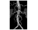
- a thin blood vessel represented by a diameter of several pixels what should actually have a high pixel value is imaged as a lower value than the actual value due to the influence of surrounding pixel values when imaging.
- the thick blood vessel portion looks fine, but is thin.
- the blood vessel portion does not appear to disappear, and as shown in FIG. 7, the color map and the opacity curve are respectively moved in equilibrium with the pixel value distribution of the thin blood vessels to apply one color map and the opacity curve.
- a thin blood vessel portion can be seen (see an area surrounded by a white line), but a thick blood vessel portion appears to be excessively expanded.
- Patent Document 1 proposes a method of dynamically correcting a color map and / or opacity curve for each image, but this method has a description range of individual images within the range. This is related to how to determine one opacity curve used to generate a single image on the assumption that fluctuations in pixel values in the image are so small that they can be ignored. However, this does not solve the above problem in the case of generating an image.
- the present invention provides an image generation apparatus and method capable of generating an image that more accurately describes a three-dimensional form of a predetermined object when generating a pseudo three-dimensional image by performing volume rendering. And to provide a program.
- An image generation apparatus includes an image generation unit that generates a pseudo three-dimensional image by performing volume rendering using an opacity curve that defines a relationship between a pixel value and opacity in a three-dimensional image;
- An area specifying unit that specifies an entire area representing a predetermined object from an image, and a base opacity curve for the specified entire area are set, and each of at least some pixels in the specified entire area is set.
- a representative value of a pixel value in the vicinity region of the pixel is acquired, and an opacity curve obtained by modifying the base opacity curve using the acquired representative value is applied to the pixel in volume rendering.
- an opacity curve setting unit set as an opacity curve to be set (first image generation apparatus).
- the opacity curve setting unit for each of at least some of the pixels, based on a subtraction value obtained by subtracting the representative value of the pixel values in the entire area from the representative value of the pixel values in the vicinity area of the pixel. And an opacity curve obtained by shifting the base opacity curve in the pixel value direction by the determined shift amount may be set as an opacity curve to be applied to the pixel in volume rendering. .
- the “pixel value direction” means that the opacity curve is set in a coordinate system in which the pixel value is on one axis (eg, the horizontal axis) and the opacity is on the other axis (eg, the vertical axis). If it is, it means the axial direction representing the pixel value.
- shift by the shift amount means that the shift is in the plus direction of the axis representing the pixel value when the shift amount is plus, and the minus direction of the axis representing the pixel value when the shift amount is minus. Means that.
- the opacity curve setting unit may represent a representative value of the pixel values in the neighboring area of each of the partial pixels obtained by sampling the pixels in the entire area at a predetermined interval.
- the opacity curve shift amount is obtained based on the difference between the obtained representative value and the representative value of the pixel values of the entire region, and the base opacity curve is moved in the pixel value direction by the obtained shift amount.
- the shifted opacity curve is set as an opacity curve to be applied to the pixel in volume rendering, and the shift amount in the pixel is estimated for each of the pixels other than a part of the sampled pixels in the entire region.
- a value is obtained by interpolation using a shift amount in each of two or more sampled pixels located in the vicinity of the pixel.
- the opacity curve only estimate the base opacity curve made by shifting the pixel value direction has been, or may be set as the opacity curve to be applied to the pixels in the volume rendering.
- the representative value of the pixel values in the neighborhood area may be a mode value, a median value, or an average value of the pixel values in the neighborhood area.
- the average value of the pixel values existing within a predetermined pixel value width range from the mode value or median value of the pixel values of the pixel values, or the pixel values in the neighboring region out of the whole pixel values in the neighboring region.
- the representative values of the pixel values in the entire region may be the same type of values as the representative values of the pixel values in the neighboring region, or may be different types of values.
- the representative value of the pixel values in the neighboring area is the average value of the pixel values in the neighboring area
- the representative value of the pixel values in the whole area may be the average value of the pixel values in the whole area.
- the mode value of the pixel values in the entire area may be used.
- the image generation unit generates a pseudo three-dimensional image by performing volume rendering using a color map that defines a relationship between a pixel value and a display color in the three-dimensional image.
- a base color map is set for the specified whole area, and for each of at least some of the pixels in the specified whole area, a representative value of the pixel values in the neighboring area of the pixel
- a color map setting unit for setting a color map to be applied to the pixel in volume rendering using a calculated representative value and a change to the base color map. Also good.
- An image generation apparatus includes an image generation unit that generates a pseudo three-dimensional image by performing volume rendering using a color map that defines a relationship between a pixel value and a display color in a three-dimensional image, and a three-dimensional image And an area specifying unit for specifying the entire area representing the predetermined object, and setting a base color map for the specified entire area, and for each of at least some pixels in the specified entire area As a color map for calculating a representative value of pixel values in the vicinity region of the pixel and applying a change to the base color map using the calculated representative value to the pixel in volume rendering And a color map setting unit for setting. (Second image generation device).
- the predetermined object may be a blood vessel.
- the first and second image processing methods of the present invention are methods in which processes performed by the respective units of the first and second image generation apparatuses are executed by at least one computer.
- the first and second image processing programs of the present invention are programs that cause at least one computer to execute the processes performed by the respective units of the first and second image display devices.
- This program is recorded on a recording medium such as a CD-ROM or DVD, or recorded in a downloadable state in a storage attached to a server computer or a network storage, and provided to the user.
- a pseudo three-dimensional image is obtained by performing volume rendering using an opacity curve that defines the relationship between pixel values and opacity in a three-dimensional image.
- a base opacity curve is set for the identified entire area, and at least some pixels in the identified entire area
- the representative value of the pixel value in the vicinity region of the pixel is obtained, and the opacity curve obtained by changing the base opacity curve using the obtained representative value is applied to the volume rendering.
- the drawing is performed for each of all the pixels in the area representing the predetermined object. It is possible to apply the opacity curve which is suitable for, can produce a more accurate representation images of three-dimensional forms of a given object. This effect is particularly noticeable when the predetermined object is a blood vessel and when the three-dimensional image is an image taken by injecting a contrast medium into the blood vessel.
- a representative value of the pixel values in the neighborhood region of the pixel is acquired.
- the amount of shift of the opacity curve is obtained based on the difference between the acquired representative value and the representative value of the pixel value of the entire area, and the base opacity curve is shifted in the pixel value direction by the obtained shift amount.
- An opacity curve is set as an opacity curve to be applied to the pixel in volume rendering, and for each pixel other than a part of the sampled pixels in the entire area, an estimated value of the shift amount in the pixel is set to the pixel.
- the computation processing can be speeded up. .
- the representative value of the pixel value in the neighboring area is the mode value or median value of the pixel value in the neighboring area, even if an extreme value due to noise exists in the pixel value in the neighboring area The value can be made difficult to be reflected in the representative value.
- the representative value of the pixel value in the neighborhood area is a pixel value that is within the predetermined pixel value width from the mode value or median value of the pixel values in the neighborhood area out of all the pixel values in the neighborhood area.
- the average value, mode value, or median value extreme values existing on the maximum side or the minimum side among the pixel values in the neighboring region can be made difficult to be reflected in the representative value.
- a base color map is set for the specified entire area, and for each of at least some pixels in the specified entire area, the base color map is set.
- a representative value of a pixel value in the vicinity region of the pixel is calculated, and a color map obtained by changing the base color map using the calculated representative value is set to a color map to be applied to the pixel in volume rendering.
- a color map suitable for the depiction can be applied to each of all the pixels in the area representing the predetermined object, and the three-dimensional form of the predetermined object can be more accurately represented. Can be generated.
- a pseudo three-dimensional image is generated by performing volume rendering using a color map that defines the relationship between pixel values and opacity in a three-dimensional image.
- a color map that defines the relationship between pixel values and opacity in a three-dimensional image.
- a representative value of the pixel value in the vicinity region of the pixel is acquired, and a color map obtained by modifying the base color map using the acquired representative value is applied to the pixel in volume rendering Since this is set as a color map to be used, a color map suitable for the depiction is applied to each of all the pixels in the area representing the predetermined object. It is to be able to be generated more accurately depict images of three-dimensional forms of a given object.
- FIG. 1 is a schematic block diagram of an image generation apparatus according to a first embodiment.
- Schematic block diagram of an image generation apparatus according to the second embodiment The flowchart which shows operation
- FIG. 1 is a block diagram illustrating a schematic configuration of the image generation apparatus 1.
- the configuration of the image generation device 1 as shown in FIG. 1 is realized by executing an image generation program read into the auxiliary storage device on a computer.
- the image generation program is stored in a storage medium such as a CD-ROM or distributed via a network such as the Internet and installed in a computer.
- the image processing program defines image acquisition processing, image generation processing, region identification processing, opacity curve setting processing, and display control processing as processing to be executed by the CPU of the computer.
- the CPU executes each of the above processes, the computer functions as an image acquisition unit 11, an image generation unit 12, a region specifying unit 13, an opacity curve setting unit 14, and a display control unit 16 which will be described later. .
- a storage device 2 such as a hard disk drive and a display device 3 such as a display are connected to the image generation device 1.
- the storage device 2 stores three-dimensional image data (three-dimensional image) obtained by photographing a predetermined object with an imaging device such as CT, MRI, PET, SPECT, and ultrasonic image.
- a three-dimensional image is a collection of pixel data in a three-dimensional space, and can be configured by laminating a plurality of tomographic images obtained by an imaging apparatus.
- the image acquisition unit 11 acquires the three-dimensional image stored in the storage device 2 and stores it in a storage device such as a hard disk drive built in the image generation device 1 or connected to the image generation device 1.
- the area specifying unit 13 specifies an entire area representing a predetermined object from the three-dimensional image acquired by the image acquiring unit 11.
- the whole area representing the predetermined object refers to an area including all the areas representing the predetermined object and not including other areas.
- the predetermined object is a blood vessel.
- the region specifying unit 13 extracts a region representing a blood vessel (hereinafter also referred to as a blood vessel region) from the three-dimensional image, and specifies the extracted region as an entire region.
- the extraction of the blood vessel region can be performed using a threshold method, a Region Growing method, a Level Set method, and other various image processing.
- the region specifying unit 13 searches for a linear structure by calculating eigenvalues of a 3 ⁇ 3 Hessian matrix for each local region in a three-dimensional image, for example.
- one of the three eigenvalues of the Hessian matrix is a value close to 0, and the other two are relatively large values.
- the eigenvector corresponding to the eigenvalue whose value is close to 0 indicates the principal axis direction of the linear structure.
- the region specifying unit 13 determines the likelihood of a linear structure based on the eigenvalues of the Hessian matrix for each local region, and for the local region where the linear structure is identified, the center point is a candidate. Detect as a point.
- the candidate point detected by the search is connected based on a predetermined algorithm.
- a tree structure composed of candidate points and blood vessel branches (edges) connecting the candidate points is constructed.
- the coordinate information of the detected candidate points and vector information indicating the direction of the blood vessel branch are stored in the memory together with the candidate point and the identifier of the blood vessel branch.
- the outline of the blood vessel is identified in a cross section perpendicular to the blood vessel path based on the surrounding pixel values.
- the shape is identified using a known segmentation technique represented by Graph-Cuts.
- the opacity curve setting unit 14 sets an opacity curve to be applied to each pixel in the blood vessel region specified by the region specifying unit 13 in volume rendering.
- the opacity curve defines the relationship between the pixel value and the opacity, and can be expressed as a function having the pixel value as a variable.
- a base opacity curve is set for a blood vessel region. For example, referring to the three-dimensional image, the distribution of the pixel values of the blood vessel region and the distribution of the surrounding pixel values are determined, and based on the distribution, a pixel value serving as a boundary separating the blood vessel region and the other region is obtained.
- an opacity curve is set in which the opacity changes from “0” to a value other than “0” or from “1” to a value other than “1”.
- the opacity curve may be one in which the opacity changes stepwise from “0” to “1”, or the opacity changes with a predetermined slope with respect to an increase or decrease in pixel value. May be.
- the opacity curve setting unit 14 applies, for each of some pixels obtained by sampling the pixels in the blood vessel region at predetermined intervals three-dimensionally (for example, a 1 cm range in the vertical and horizontal directions).
- the subtracted value obtained by subtracting the average value of the pixel values in the blood region from the average value of the pixel values in the (region)) is obtained as the shift amount of the opacity curve, and the base opacity curve in the pixel value direction by the determined shift amount
- the shifted opacity curve is set as the opacity curve to be applied to the pixel.
- the opacity curve setting unit 14 sets the pixel value as the variable v, the base opacity curve as OD (v), and the determined movement amount as m, for each of the sampled pixels.
- An opacity curve represented by O (v) OD (vm) is set.
- the opacity curve setting unit 14 sets two or more estimated values of shift amounts of pixels in the vicinity of the pixels other than the sampled partial pixels in the blood vessel region.
- the image generation unit 12 generates a pseudo 3D image by performing volume rendering on the 3D image using the opacity curve set by the opacity curve setting unit 14.
- the display control unit 16 causes the display device 3 to display the pseudo 3D image generated by the image generation unit 12.
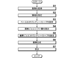
- FIG. 2 is a flowchart showing the operation of the image generation apparatus 1.
- the image acquisition unit 11 acquires a three-dimensional image stored in the storage device 2 (S1).
- the region specifying unit 13 extracts an entire region representing a blood vessel from the three-dimensional image acquired by the image acquiring unit 11, and specifies the extracted region as the entire region (S2).
- the opacity curve setting unit 14 sets a base opacity curve for the blood vessel region (S3).
- the opacity curve setting unit 14 determines, for each of a part of pixels obtained by sampling the pixels in the blood vessel region at a predetermined interval three-dimensionally, from the average value of the pixel values in the neighboring region of the pixel.
- the subtracted value obtained by subtracting the average value of the pixel values is obtained as the shift amount of the opacity curve, and for each of the pixels other than some of the sampled pixels, an estimated value of the shift amount in the pixel is located in the vicinity of the pixel.
- the amount of shift in each of the two or more sampled pixels is obtained by interpolation (S4).
- the opacity curve setting unit 14 shifts the base opacity curve in the pixel value direction by the shift amount determined in step S3 for each of the pixels other than the sampled partial pixels. Is set as an opacity curve to be applied to the pixel, and the base opacity curve is shifted in the pixel value direction by the estimated value determined in step S3 for each of the non-sampled pixels. The opacity curve is set as an opacity curve to be applied to the pixel (S5).
- the image generation unit 12 generates a pseudo 3D image by performing volume rendering on the 3D image using the opacity curve set by the opacity curve setting unit 14 (S6). Then, the display control unit 16 displays the generated pseudo three-dimensional image on the display device 3 (S7), and ends the process.
- the region specifying unit 13 specifies an entire region representing a blood vessel from the three-dimensional image
- the opacity curve setting unit 14 sets a base opacity curve for the specified entire region, and the entire region
- the curve is set as an opacity curve to be applied to the pixel in volume rendering, and the image generation unit 12 generates a pseudo three-dimensional image by performing volume rendering using the set opacity curve.
- an opacity curve suitable for the depiction can be applied to each of all the pixels in the region representing the blood vessel, and an image that more accurately depicts the three-dimensional shape of the blood vessel. Can be generated.
- FIG. 3 shows an image generation apparatus according to the second embodiment of the present invention.
- the image generation apparatus 100 of the present embodiment includes a color map setting unit 15 in addition to the configuration of the projection image generation apparatus 10 of the first embodiment shown in FIG. Other points are the same as in the first embodiment.
- the color map setting unit 15 sets a color map to be applied to each pixel in the blood vessel region specified by the region specifying unit 13 in volume rendering.
- the color map defines the relationship between the pixel value and the display color, and can be expressed as a function having the pixel value as a variable. Specifically, first, a base color map is set for the blood vessel region. Subsequently, the color map setting unit 15 applies, for each of some pixels obtained by sampling the pixels in the blood vessel region at a predetermined interval three-dimensionally (for example, in the 1 cm range in the vertical and horizontal directions).
- the subtraction value obtained by subtracting the average value of the pixel values of the blood region from the average value of the pixel values in (region) is obtained as the shift amount of the color map, and the base color map is shifted in the pixel value direction by the determined shift amount. Is set as a color map to be applied to the pixel.
- the color map setting unit 15 sets, for each of the pixels other than the sampled partial pixels in the blood vessel region, two or more estimated values of shift amounts in the pixels located in the vicinity of the pixels.
- a color map obtained by performing interpolation using the shift amount in each of the sampled pixels and shifting the base color map in the pixel value direction by the determined estimated value is set as a color map to be applied to the pixel.
- the color map setting unit 15 does not perform the process of calculating those values, and the opacity curve setting unit 15 14 can be used to set a color map to be applied to each pixel in the blood vessel region.
- the opacity curve setting unit 14 may set an opacity curve to be applied to each pixel in the blood vessel region using the shift amount and the estimated value obtained by the color map setting unit 15.
- the image generation unit 12 generates a pseudo three-dimensional image by performing volume rendering on the three-dimensional image using the opacity curve set by the opacity curve setting unit 14 and the color map set by the color map setting unit 15. .
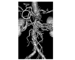
- FIG. 5 shows an example of a pseudo three-dimensional image generated by the image generation apparatus 100 of the present embodiment.
- the three-dimensional shape of the entire blood vessel is more accurately depicted as compared to the images of FIGS. 6 and 7 generated by performing volume rendering on the same three-dimensional image according to the conventional technique. Yes.
- FIG. 4 is a flowchart showing the operation of the image generation apparatus 100.
- the image acquisition unit 11 acquires a three-dimensional image stored in the storage device 2 (S11).
- the region specifying unit 13 extracts an entire region representing a blood vessel from the three-dimensional image acquired by the image acquiring unit 11, and specifies the extracted region as the entire region (S12).
- the opacity curve setting unit 14 sets a base opacity curve for the blood vessel region
- the color map setting unit 15 sets a base color map for the blood vessel region (S13).
- the opacity curve setting unit 14 or the color map setting unit 15 sets the pixel value in the vicinity region of each of the partial pixels obtained by sampling the pixels in the blood vessel region at predetermined intervals three-dimensionally.
- the subtraction value obtained by subtracting the average value of the blood region pixel values from the average value is obtained as a shift amount, and for each of the pixels other than some of the sampled pixels, an estimated value of the shift amount in the pixel is set in the vicinity of the pixel.
- a shift amount in each of the two or more sampled pixels located is obtained by interpolation (S14).
- the opacity curve setting unit 14 converts an opacity curve obtained by shifting the base opacity curve in the pixel value direction by the shift amount determined in step S14 for each of the sampled partial pixels.
- the opacity curve obtained by shifting the base opacity curve in the pixel value direction by the estimated value determined in step S14 for each of the pixels other than a part of the sampled pixels. Is set as an opacity curve to be applied to the pixel.
- the color map setting unit 15 applies, to each pixel, a color map obtained by shifting the base color map in the pixel value direction by the shift amount determined in step S14 for each of the sampled pixels.
- a color map is set as a color map, and a color map obtained by shifting the base color map in the pixel value direction by the estimated value determined in step S14 is applied to each pixel other than some of the sampled pixels.
- a color map is set (S15).
- the image generation unit 12 performs volume rendering on the three-dimensional image using the opacity curve set by the opacity curve setting unit 14 and the color map set by the color map setting unit 15, thereby performing a pseudo three-dimensional image. Is generated (S16). Then, the display control unit 16 displays the generated pseudo three-dimensional image on the display device 3 (S17), and ends the process.
- the region specifying unit 13 specifies an entire region representing a blood vessel from the three-dimensional image
- the opacity curve setting unit 14 sets a base opacity curve for the specified entire region, and the entire region
- an opacity is obtained by obtaining a representative value of the pixel value in the vicinity region of the pixel and changing the base opacity curve using the obtained representative value.
- the curve is set as an opacity curve to be applied to the pixel in volume rendering, and the color map setting unit 15 sets a base color map for the specified entire area, and sets at least some of the pixels in the entire area.
- both the opacity curve and the color map applied to each pixel in the blood vessel region are obtained by transforming the base opacity curve or the base color map, respectively.
- the base opacity curve may be used as it is, and only the color map obtained by modifying the base color map may be used.
- the shift amount is calculated only for a part of pixels obtained by sampling the pixels in the blood vessel region three-dimensionally at a predetermined interval, and the estimated value of the shift amount is calculated for each of the other pixels. Described by substituting the representative value of the blood region pixel value from the representative value of the pixel value in the neighboring region of each pixel for each of the pixels in the blood vessel region. A shift amount may be obtained based on the value, and an opacity curve and / or a color map applied to the pixel may be set using the determined shift amount.
- the shift amount or the estimated value is obtained for each pixel.
- the shift amount or the estimated value is obtained for each small region including two or more pixels, and the obtained shift is obtained.
- the opacity curve and / or color map obtained based on the quantity or the estimated value may be applied to all the pixels in the small area.
- the opacity curve setting unit 14 acquires a representative value of the pixel values in the partial area for each of the partial areas having a predetermined size constituting the entire area specified by the area specifying unit 13, An opacity curve obtained by changing the base opacity curve using the acquired representative value may be set as an opacity curve to be applied to the partial region in volume rendering, or the region specifying unit 13 For each of the partial areas of a predetermined size constituting the entire area specified by the above, a representative value of a pixel value in a neighboring area including the partial area is acquired, and the setting is performed using the acquired representative value.
- the color map setting unit 15 acquires a representative value of the pixel value in the partial area for each of the partial areas having a predetermined size constituting the entire area specified by the area specifying unit 13, A color map obtained by changing the base color map using the acquired representative value may be set as a color map to be applied to the partial area in volume rendering, or may be specified by the area specifying unit 13. For each partial area of a predetermined size constituting the entire area, a representative value of pixel values in a neighboring area including the partial area is acquired, and the set base is obtained using the acquired representative value. A color map obtained by changing the color map may be set as a color map to be applied to the partial area in the volume rendering.
- the predetermined object is a blood vessel
- the predetermined object may be a structure having a tubular structure such as an intestine or a bronchus, It may be various organs such as the liver.
- the representative value of the pixel value may be the mode value or the median value of the pixel values in the area, or the mode value of the pixel values in the area out of all the pixel values in the area or
- the average value of the pixel values existing within the range of the predetermined pixel value width from the median value may be used, or the mode value or median value of the pixel values in the region out of all the pixel values in the region. It may be a mode value or a median value of pixel values existing within a predetermined pixel value width.
- the representative values of the pixel values in the entire region may be the same type of values as the representative values of the pixel values in the neighboring region, or may be different types of values.
- the surface of a predetermined object can also be drawn by the volume rendering.
Landscapes
- Health & Medical Sciences (AREA)
- Life Sciences & Earth Sciences (AREA)
- Engineering & Computer Science (AREA)
- Medical Informatics (AREA)
- Physics & Mathematics (AREA)
- Animal Behavior & Ethology (AREA)
- Veterinary Medicine (AREA)
- Radiology & Medical Imaging (AREA)
- Nuclear Medicine, Radiotherapy & Molecular Imaging (AREA)
- Biomedical Technology (AREA)
- Heart & Thoracic Surgery (AREA)
- Biophysics (AREA)
- Molecular Biology (AREA)
- Surgery (AREA)
- Pathology (AREA)
- General Health & Medical Sciences (AREA)
- Public Health (AREA)
- Computer Graphics (AREA)
- Vascular Medicine (AREA)
- High Energy & Nuclear Physics (AREA)
- Optics & Photonics (AREA)
- General Physics & Mathematics (AREA)
- Theoretical Computer Science (AREA)
- General Engineering & Computer Science (AREA)
- Human Computer Interaction (AREA)
- Dentistry (AREA)
- Oral & Maxillofacial Surgery (AREA)
- Apparatus For Radiation Diagnosis (AREA)
- Image Generation (AREA)
- Measuring And Recording Apparatus For Diagnosis (AREA)
Priority Applications (4)
| Application Number | Priority Date | Filing Date | Title |
|---|---|---|---|
| CN201380014286.2A CN104205172A (zh) | 2012-03-14 | 2013-03-13 | 图像生成装置、方法以及程序 |
| EP13762032.4A EP2827301B1 (en) | 2012-03-14 | 2013-03-13 | Image generation device, method, and program |
| US14/483,376 US9563978B2 (en) | 2012-03-14 | 2014-09-11 | Image generation apparatus, method, and medium with image generation program recorded thereon |
| IN7725DEN2014 IN2014DN07725A (https=) | 2012-03-14 | 2014-09-16 |
Applications Claiming Priority (2)
| Application Number | Priority Date | Filing Date | Title |
|---|---|---|---|
| JP2012-056977 | 2012-03-14 | ||
| JP2012056977A JP5814838B2 (ja) | 2012-03-14 | 2012-03-14 | 画像生成装置、方法及びプログラム |
Related Child Applications (1)
| Application Number | Title | Priority Date | Filing Date |
|---|---|---|---|
| US14/483,376 Continuation US9563978B2 (en) | 2012-03-14 | 2014-09-11 | Image generation apparatus, method, and medium with image generation program recorded thereon |
Publications (1)
| Publication Number | Publication Date |
|---|---|
| WO2013136783A1 true WO2013136783A1 (ja) | 2013-09-19 |
Family
ID=49160711
Family Applications (1)
| Application Number | Title | Priority Date | Filing Date |
|---|---|---|---|
| PCT/JP2013/001634 Ceased WO2013136783A1 (ja) | 2012-03-14 | 2013-03-13 | 画像生成装置、方法及びプログラム |
Country Status (6)
| Country | Link |
|---|---|
| US (1) | US9563978B2 (https=) |
| EP (1) | EP2827301B1 (https=) |
| JP (1) | JP5814838B2 (https=) |
| CN (1) | CN104205172A (https=) |
| IN (1) | IN2014DN07725A (https=) |
| WO (1) | WO2013136783A1 (https=) |
Families Citing this family (13)
| Publication number | Priority date | Publication date | Assignee | Title |
|---|---|---|---|---|
| JP6543099B2 (ja) * | 2015-06-01 | 2019-07-10 | シーフォーシー・メディカル・ソフトウェア,インコーポレーテッド | 情報処理装置、情報処理方法、およびプログラム |
| JP6521250B2 (ja) * | 2015-09-25 | 2019-05-29 | 京セラドキュメントソリューションズ株式会社 | 画像形成装置、色変換プログラムおよび色変換方法 |
| JP6671946B2 (ja) * | 2015-12-11 | 2020-03-25 | キヤノン株式会社 | 情報取得装置、撮像装置及び情報取得方法 |
| US10467798B2 (en) * | 2016-12-19 | 2019-11-05 | Canon Medical Systems Corporation | Rendering a global illumination image from a volumetric medical imaging data set |
| JP7013849B2 (ja) * | 2017-12-22 | 2022-02-01 | 大日本印刷株式会社 | コンピュータプログラム、画像処理装置及び画像処理方法 |
| JP2019114034A (ja) * | 2017-12-22 | 2019-07-11 | 大日本印刷株式会社 | コンピュータプログラム、画像処理装置、画像処理方法及びボクセルデータ |
| JP7003635B2 (ja) * | 2017-12-22 | 2022-01-20 | 大日本印刷株式会社 | コンピュータプログラム、画像処理装置及び画像処理方法 |
| JP6436258B1 (ja) * | 2018-03-27 | 2018-12-12 | 大日本印刷株式会社 | コンピュータプログラム、画像処理装置及び画像処理方法 |
| JP7206617B2 (ja) * | 2018-04-12 | 2023-01-18 | 大日本印刷株式会社 | 断層画像表示用カラーマップの最適化装置およびボリュームレンダリング装置 |
| CN110069310B (zh) * | 2019-04-23 | 2022-04-22 | 北京小米移动软件有限公司 | 切换桌面壁纸的方法、装置及存储介质 |
| CN110211216B (zh) * | 2019-06-14 | 2020-11-03 | 北京理工大学 | 一种基于体绘制不透明度加权的三维图像空域融合方法 |
| US11443476B2 (en) * | 2020-05-27 | 2022-09-13 | Canon Medical Systems Corporation | Image data processing method and apparatus |
| JP7653247B2 (ja) * | 2020-12-07 | 2025-03-28 | 富士フイルム株式会社 | 磁気共鳴イメージング装置、画像処理装置および画像処理方法 |
Citations (3)
| Publication number | Priority date | Publication date | Assignee | Title |
|---|---|---|---|---|
| JP2004283373A (ja) * | 2003-03-20 | 2004-10-14 | Toshiba Corp | 管腔状構造体の解析処理装置 |
| JP2008086658A (ja) * | 2006-10-04 | 2008-04-17 | Fujifilm Corp | 画像表示装置および画像表示プログラム |
| JP2011212219A (ja) * | 2010-03-31 | 2011-10-27 | Fujifilm Corp | 投影画像生成装置、方法、及びプログラム |
Family Cites Families (2)
| Publication number | Priority date | Publication date | Assignee | Title |
|---|---|---|---|---|
| JP5576117B2 (ja) * | 2006-07-31 | 2014-08-20 | コーニンクレッカ フィリップス エヌ ヴェ | 画像データセットの視覚化のためのプリセットマップを生成する方法、装置及びコンピュータ可読媒体 |
| US7990378B2 (en) * | 2007-05-07 | 2011-08-02 | General Electric Company | Methods and apparatus for volume rendering |
-
2012
- 2012-03-14 JP JP2012056977A patent/JP5814838B2/ja active Active
-
2013
- 2013-03-13 WO PCT/JP2013/001634 patent/WO2013136783A1/ja not_active Ceased
- 2013-03-13 EP EP13762032.4A patent/EP2827301B1/en active Active
- 2013-03-13 CN CN201380014286.2A patent/CN104205172A/zh active Pending
-
2014
- 2014-09-11 US US14/483,376 patent/US9563978B2/en active Active
- 2014-09-16 IN IN7725DEN2014 patent/IN2014DN07725A/en unknown
Patent Citations (3)
| Publication number | Priority date | Publication date | Assignee | Title |
|---|---|---|---|---|
| JP2004283373A (ja) * | 2003-03-20 | 2004-10-14 | Toshiba Corp | 管腔状構造体の解析処理装置 |
| JP2008086658A (ja) * | 2006-10-04 | 2008-04-17 | Fujifilm Corp | 画像表示装置および画像表示プログラム |
| JP2011212219A (ja) * | 2010-03-31 | 2011-10-27 | Fujifilm Corp | 投影画像生成装置、方法、及びプログラム |
Non-Patent Citations (1)
| Title |
|---|
| H. IMAI: "I see!! The Bible of the Way of Thinking and Processing - Three-Dimensional Medical Image", SHUJUNSHA, 2003, pages 105 |
Also Published As
| Publication number | Publication date |
|---|---|
| EP2827301B1 (en) | 2019-08-21 |
| EP2827301A1 (en) | 2015-01-21 |
| JP2013191030A (ja) | 2013-09-26 |
| US20140375631A1 (en) | 2014-12-25 |
| EP2827301A4 (en) | 2015-11-25 |
| IN2014DN07725A (https=) | 2015-06-26 |
| CN104205172A (zh) | 2014-12-10 |
| US9563978B2 (en) | 2017-02-07 |
| JP5814838B2 (ja) | 2015-11-17 |
Similar Documents
| Publication | Publication Date | Title |
|---|---|---|
| JP5814838B2 (ja) | 画像生成装置、方法及びプログラム | |
| CN102208118B (zh) | 投影图像生成方法和设备 | |
| US7990379B2 (en) | System and method for coronary segmentation and visualization | |
| KR101805619B1 (ko) | 3차원 의료 영상으로부터 최적의 2차원 의료 영상을 자동으로 생성하는 방법 및 장치 | |
| EP2856428B1 (en) | Segmentation highlighter | |
| US9472017B2 (en) | Fast rendering of curved reformation of a 3D tubular structure | |
| JP6133026B2 (ja) | 三次元画像をナビゲートし、セグメント化し、抽出するための方法及びシステム | |
| EP1846896B1 (en) | A method, a system and a computer program for integration of medical diagnostic information and a geometric model of a movable body | |
| JP6093347B2 (ja) | 医療画像処理システム及び方法 | |
| JP2006167287A (ja) | 血管狭窄率解析システム | |
| JP6820805B2 (ja) | 画像位置合わせ装置、その作動方法およびプログラム | |
| JP4212564B2 (ja) | 画像処理方法および画像処理プログラム | |
| WO2010098444A1 (ja) | 医用画像処理装置及び方法 | |
| JP4885042B2 (ja) | 画像処理方法および装置ならびにプログラム | |
| JP2010000306A (ja) | 医用画像診断装置、画像処理装置、及びプログラム | |
| KR20150110143A (ko) | 볼륨 렌더링 장치 및 그 동작방법 | |
| EP3828836B1 (en) | Method and data processing system for providing a two-dimensional unfolded image of at least one tubular structure | |
| JP2006326312A (ja) | 多分岐された血管および該血管の周囲環境を単一のイメージに同時に投影する方法 | |
| EP3607527B1 (en) | Quantitative evaluation of time-varying data | |
| JP4896470B2 (ja) | 画像処理装置、医用画像診断装置及び画像処理方法 | |
| JP2008200524A (ja) | 画像処理方法 | |
| JP2008246215A (ja) | 画像処理方法 | |
| KR20120110811A (ko) | 가상 엔도스코프를 이용한 뇌수술 항법의 정확도 향상 방법 | |
| Cash et al. | Centroid-based Maximum intensity projections |
Legal Events
| Date | Code | Title | Description |
|---|---|---|---|
| 121 | Ep: the epo has been informed by wipo that ep was designated in this application |
Ref document number: 13762032 Country of ref document: EP Kind code of ref document: A1 |
|
| NENP | Non-entry into the national phase |
Ref country code: DE |
|
| WWE | Wipo information: entry into national phase |
Ref document number: 2013762032 Country of ref document: EP |