WO2013136773A1 - Steam generator and heating cooker comprising steam generator - Google Patents
Steam generator and heating cooker comprising steam generator Download PDFInfo
- Publication number
- WO2013136773A1 WO2013136773A1 PCT/JP2013/001608 JP2013001608W WO2013136773A1 WO 2013136773 A1 WO2013136773 A1 WO 2013136773A1 JP 2013001608 W JP2013001608 W JP 2013001608W WO 2013136773 A1 WO2013136773 A1 WO 2013136773A1
- Authority
- WO
- WIPO (PCT)
- Prior art keywords
- water
- drainage channel
- drainage
- steam generator
- storage chamber
- Prior art date
Links
Images


Classifications
-
- F—MECHANICAL ENGINEERING; LIGHTING; HEATING; WEAPONS; BLASTING
- F22—STEAM GENERATION
- F22B—METHODS OF STEAM GENERATION; STEAM BOILERS
- F22B1/00—Methods of steam generation characterised by form of heating method
- F22B1/28—Methods of steam generation characterised by form of heating method in boilers heated electrically
- F22B1/284—Methods of steam generation characterised by form of heating method in boilers heated electrically with water in reservoirs
-
- A—HUMAN NECESSITIES
- A47—FURNITURE; DOMESTIC ARTICLES OR APPLIANCES; COFFEE MILLS; SPICE MILLS; SUCTION CLEANERS IN GENERAL
- A47J—KITCHEN EQUIPMENT; COFFEE MILLS; SPICE MILLS; APPARATUS FOR MAKING BEVERAGES
- A47J27/00—Cooking-vessels
- A47J27/04—Cooking-vessels for cooking food in steam; Devices for extracting fruit juice by means of steam ; Vacuum cooking vessels
-
- F—MECHANICAL ENGINEERING; LIGHTING; HEATING; WEAPONS; BLASTING
- F22—STEAM GENERATION
- F22B—METHODS OF STEAM GENERATION; STEAM BOILERS
- F22B1/00—Methods of steam generation characterised by form of heating method
- F22B1/28—Methods of steam generation characterised by form of heating method in boilers heated electrically
- F22B1/284—Methods of steam generation characterised by form of heating method in boilers heated electrically with water in reservoirs
- F22B1/285—Methods of steam generation characterised by form of heating method in boilers heated electrically with water in reservoirs the water being fed by a pump to the reservoirs
-
- F—MECHANICAL ENGINEERING; LIGHTING; HEATING; WEAPONS; BLASTING
- F22—STEAM GENERATION
- F22B—METHODS OF STEAM GENERATION; STEAM BOILERS
- F22B37/00—Component parts or details of steam boilers
- F22B37/02—Component parts or details of steam boilers applicable to more than one kind or type of steam boiler
- F22B37/48—Devices for removing water, salt, or sludge from boilers; Arrangements of cleaning apparatus in boilers; Combinations thereof with boilers
- F22B37/50—Devices for removing water, salt, or sludge from boilers; Arrangements of cleaning apparatus in boilers; Combinations thereof with boilers for draining or expelling water
-
- F—MECHANICAL ENGINEERING; LIGHTING; HEATING; WEAPONS; BLASTING
- F22—STEAM GENERATION
- F22B—METHODS OF STEAM GENERATION; STEAM BOILERS
- F22B37/00—Component parts or details of steam boilers
- F22B37/02—Component parts or details of steam boilers applicable to more than one kind or type of steam boiler
- F22B37/48—Devices for removing water, salt, or sludge from boilers; Arrangements of cleaning apparatus in boilers; Combinations thereof with boilers
- F22B37/54—De-sludging or blow-down devices
-
- F—MECHANICAL ENGINEERING; LIGHTING; HEATING; WEAPONS; BLASTING
- F24—HEATING; RANGES; VENTILATING
- F24C—DOMESTIC STOVES OR RANGES ; DETAILS OF DOMESTIC STOVES OR RANGES, OF GENERAL APPLICATION
- F24C15/00—Details
- F24C15/003—Details moisturising of air
-
- F—MECHANICAL ENGINEERING; LIGHTING; HEATING; WEAPONS; BLASTING
- F24—HEATING; RANGES; VENTILATING
- F24C—DOMESTIC STOVES OR RANGES ; DETAILS OF DOMESTIC STOVES OR RANGES, OF GENERAL APPLICATION
- F24C15/00—Details
- F24C15/32—Arrangements of ducts for hot gases, e.g. in or around baking ovens
- F24C15/322—Arrangements of ducts for hot gases, e.g. in or around baking ovens with forced circulation
- F24C15/327—Arrangements of ducts for hot gases, e.g. in or around baking ovens with forced circulation with air moisturising
-
- A—HUMAN NECESSITIES
- A47—FURNITURE; DOMESTIC ARTICLES OR APPLIANCES; COFFEE MILLS; SPICE MILLS; SUCTION CLEANERS IN GENERAL
- A47J—KITCHEN EQUIPMENT; COFFEE MILLS; SPICE MILLS; APPARATUS FOR MAKING BEVERAGES
- A47J27/00—Cooking-vessels
- A47J27/04—Cooking-vessels for cooking food in steam; Devices for extracting fruit juice by means of steam ; Vacuum cooking vessels
- A47J2027/043—Cooking-vessels for cooking food in steam; Devices for extracting fruit juice by means of steam ; Vacuum cooking vessels for cooking food in steam
Definitions
- the present invention relates to a steam generator and a cooking device equipped with the steam generator.
- a steam generator includes a first tank used as a liquid supply source, a second tank as an evaporation chamber, a liquid supply pipe for supplying liquid from the first tank to the second tank, and a first tank from the second tank. And a drain pipe for draining into the tank.
- a cleaning operation is performed in order to remove the scale attached to the second tank.
- liquid is supplied until the liquid level in the second tank reaches a level exceeding the apex of the bent drainage pipe, and the liquid in the second tank is drained into the first tank according to the siphon principle.
- the scale in 2 tanks was discharged.
- Patent Document 1 although it does not specify about the material of a drainage pipe, generally a metal pipe is bent and used as such a liquid distribution pipe.
- the scale component adhering in the second tank is composed of an inorganic substance such as calcium carbonate or magnesium carbonate, and therefore has a strong bond with metal and is composed of metal. It also adheres to the drain.
- the U-shaped part that protrudes downward is structurally provided below the second tank, so that steam is generated in the second tank.
- the deposited scale has a structure that is likely to settle and accumulate. For this reason, the scale gradually adheres to the inside of the drainage pipe due to long-term use, and eventually drainage becomes impossible. As a result, the scale accumulates in the second tank and steam generation becomes impossible. It had the problem of end.
- the present invention solves the problems in the conventional steam generator, and it is difficult for the scale to be firmly fixed in the drainage pipe, and the steam generator can maintain the steam generation performance even if it is used for a long period of time. And it aims at providing the heating cooker provided with the steam generator.
- the steam generator of the present invention includes a water storage chamber for storing water, a heating unit for heating the water in the water storage chamber, a water supply device for sending water from a water supply tank through a water supply port and a water supply path provided in the water storage chamber, A drainage channel for draining the water in the reservoir,
- the drainage channel is provided with a U-shaped first drainage channel that protrudes downward through a drainage port provided in the water storage chamber, and is provided continuously with the first drainage channel and protrudes upward.
- An inverted U-shaped second drainage channel, and a position above the position of the water surface stored during normal heating in the reservoir is defined as a drainage channel apex, and the water supply device is operated to operate the drainage channel apex
- the water supply device is operated to operate the drainage channel apex
- at least the inner surface of the first drainage channel is made of a non-metal. It is configured.
- the bond with the scale is weakly fixed. Therefore, it is easy to discharge the scale when drained according to the siphon principle, and it is possible to provide a steam generator that does not deteriorate the steam generation performance even if it is used for a long period of time.
- the scale is difficult to adhere to the drainage channel, and the steam generation performance can be maintained without changing even if the scale is used for a long time.
- FIG. 1 Front sectional drawing of the cooking-by-heating machine provided with the steam generator of Embodiment 1 which concerns on this invention.
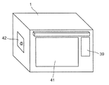
- the perspective view which shows the external appearance of the heating cooker provided with the steam generator of Embodiment 1 which concerns on this invention.
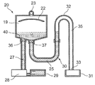
- Sectional drawing which shows typically the structure of the steam generator of Embodiment 1 which concerns on this invention.
- Sectional drawing which shows the 1st operation
- Sectional drawing which shows the 3rd operation
- Sectional drawing which shows the 4th operation
- the steam generator comprises: A water reservoir for storing water, A heating unit for heating water in the water storage chamber; A water supply device that sends water from a water supply tank through a water supply port and a water supply channel provided in the water storage chamber, and a drainage channel that drains water from the water storage chamber,
- the drainage channel is provided with a U-shaped first drainage channel that protrudes downward through a drainage port provided in the water storage chamber, and is provided continuously with the first drainage channel and protrudes upward.
- an inverted U-shaped second drainage channel is located above the position of the water surface stored during normal heating in the water storage chamber, and the water supply device is operated. By pushing up the water level to the top of the drainage channel, the water stored in the water storage chamber is drained through the drainage port and the drainage channel according to the principle of siphon, and at least of the first drainage channel.
- the inner surface is made of non-metal.
- At least the inner surface of the first drainage channel that is structurally prone to sedimentation and accumulation is composed of a non-metal, Steam generator that prevents the first drainage channel from being fixed due to weak coupling with the scale, the scale is reliably discharged when drained according to the siphon principle, and the steam generation performance does not deteriorate even if it is used for a long time Can be provided.
- the first drainage path in the drainage path is made of a non-metal.
- the first drainage channel which is structurally easy to settle and accumulate, is made of non-metal, so the principle of siphon It is possible to provide a steam generating apparatus in which the scale is reliably discharged when drained and the steam generating performance does not deteriorate even if the scale is continuously used for a long time.
- the first drainage channel in the drainage channel is made of a nonmetal
- the first The non-metal portion of the first drainage channel is made of a transparent member so that the internal state of the drainage channel can be visually confirmed.
- the user can visually check the scale accumulation in the first drainage channel and drain the water. There is no need to waste water when it is not collected, and when drainage is needed, the scale can be discharged reliably when drained according to the siphon principle at an appropriate timing, and steam is generated even if it is used for a long time. It is possible to provide a steam generator that does not deteriorate in performance.
- the second drainage channel is made of metal.
- the second drainage channel by configuring the second drainage channel with metal, a structure that can be easily fixed to the apparatus main body can be obtained, and an inexpensive configuration is provided. It can be.
- the steam generator according to the fifth aspect of the present invention is the steam generator according to any one of the first to fourth aspects, particularly, wherein at least the first drainage channel in the drainage channel is made of a non-metal.
- the non-metal part of the first drainage channel is made of an elastic body.
- a drain port portion that is a connection portion between the water storage chamber and the first drainage channel, and the water storage chamber and the second drainage channel.
- the connecting portion can be configured without using a separate part such as a tube. For this reason, it becomes the structure which can prevent the water leak etc. by the number of parts increasing, and it can be set as a reliable and cheap structure.
- a non-metallic coating layer is formed on the inner surface of the first drainage channel.
- the heating cooker according to the seventh aspect of the present invention includes the steam generator according to any one of the first to sixth aspects.
- the heating cooker according to the seventh aspect of the present invention configured as described above since the first drainage channel that tends to settle and accumulate is non-metallic, the coupling with the scale becomes weak, and the scale is Heat cooking with a steam generator that prevents sticking to the first drainage channel and can discharge the scale at the same time when draining according to the siphon principle, and does not deteriorate the steam generation performance even if it is used for a long time. Can be provided.
- FIG. 1 shows a front cross-sectional view of a cooking device provided with the steam generator according to Embodiment 1 of the present invention.
- the heating cooker according to the first embodiment has a heating chamber 1 configured by fluorine-coating the surface of an aluminized steel sheet and storing a food 5 that is a heated object.
- a mounting table 3 made of a vitrified glass and three heating chamber heaters 2 provided in parallel near the top surface of the heating chamber 1 are provided. Of the three heating chamber heaters 2, the wavelength peak value of the heating chamber heater 2 disposed at the center is set shorter than the wavelength peak values of the other two heating chamber heaters 2.
- the wall surface constituting the heating chamber 1 is connected to a ground wire (not shown) and grounded, and the rail 12 integrally molded with the heating chamber 1 is also in a grounded state.
- the wall surface constituting the heating chamber 1 in the first embodiment will be described with an example in which fluorine coating is applied to easily remove dirt, enamel coating or other heat-resistant coating may be performed.
- the example which used the aluminum plating steel plate is demonstrated as a material of the heating chamber 1, another metal may be used, for example, stainless steel can also be used.
- the mounting plate 4 is formed of an aluminum-plated steel plate, and is unevenly processed with a press so that the oil and fat from the food 5 can easily flow out when the food 5 on the mounting plate 4 is heated.
- the surface of the mounting tray 4 is coated with fluorine, and the back surface is provided with a heating element that absorbs microwaves and generates heat.
- a heating element on the back surface of the mounting dish 4
- the both sides of the food 5 are obtained by combining the heating chamber heater 2 provided above the food 5 and the heating element on the back surface of the mounting dish 4. Can be heated.
- the molded product of PPS resin is provided in order to insulate from the heating chamber 1 in the contact part of the mounting tray 4 and the rail 12.
- the surface of the mounting plate 4 will be described with an example in which fluorine coating is applied to easily remove dirt, but enamel coating or other heat-resistant coating may be performed.
- the example of aluminum was demonstrated as a material of the mounting tray 4, another metal, for example, stainless steel, can also be used.
- a circulation fan 7 that stirs and circulates the air in the heating chamber 1 and a convection heater 8 that is an indoor heater that heats the air that circulates in the heating chamber 1 are provided on the back side, which is the back of the heating chamber 1. Is provided so as to surround. Near the center of the back surface of the heating chamber 1, a plurality of intake vent holes 16 are formed for intake from the heating chamber 1 side to the circulation fan 7 side. Conversely, a plurality of ventilation holes 17 for blowing air from the circulation fan 7 side to the heating chamber 1 side are formed in a specific area in the outer peripheral region of the convection heater 8 on the back surface of the heating chamber 1. . Each ventilation hole 16 and 17 is formed with many punching holes.
- the heating cooker according to the first embodiment has a detection hole 38 formed on the right wall surface (right wall surface) constituting the heating chamber 1, and the heating chamber passes through the detection hole 38.
- the temperature of the food 5 in 1 is detected by the infrared sensor 15, and the internal temperature of the heating chamber 1 is detected by an internal thermistor 9 provided in the upper part of the heating chamber 1.
- a magnetron 6 as a microwave generating means is provided below the left wall surface below the heating chamber 1 so that the output end is led out in the horizontal direction.
- the magnetron 6 used in the first embodiment is about 80 mm ⁇ 80 mm square when viewed from the left in FIG.
- the magnetron 6 is connected to a waveguide 14 having a substantially L-shaped internal passage by bending an aluminized steel plate just below the bottom surface of the heating chamber 1.
- the output end of the magnetron 6 led out in the horizontal direction is led out into the waveguide 14, and the microwave from the magnetron 6 is configured to transmit the internal passage of the waveguide 14.
- a rotating antenna 11 made of aluminum is provided in the vicinity of the center of the bottom surface of the heating chamber 1, and the rotating antenna 11 passes through an opening from the inside of the waveguide 14 immediately below the bottom surface of the heating chamber 1 and passes through the opening in the heating chamber 1.
- Projected to The rotating antenna 11 is configured to be rotated by a motor 18 and has a function as a radio wave agitating means for agitating the microwave radiated from the waveguide 14 into the heating chamber 1.
- the magnetron 6, the rotating antenna 11, the motor 18, and the waveguide 14 are provided on the lower side of the heating chamber 1, but the present invention is limited to this configuration. However, these elements can be provided on the upper side or the side of the heating chamber 1, and the installation direction of each element can be set in any direction corresponding to each element. .
- a steam generator 20 is provided in the heating cooker according to Embodiment 1 configured as described above. As shown in FIG. 1, when the cooking device is viewed from the front, on the left side of the heating chamber 1, a water storage chamber 19 for storing water for generating steam in the steam generator 20 and the water storage chamber 19 are heated. In addition, a steam generation heater 40 which is a heating unit that generates steam in the water storage chamber 19 is provided. Further, a water storage chamber thermistor 34 for measuring the temperature in the water storage chamber 19 is provided in the vicinity of the upper side of the steam generating heater 40.
- a steam introduction path 23 is joined to the top surface of the water storage chamber 19 so as to lead out upward.
- the steam introduction path 23 is led upward from the water storage chamber 19, and then bent into an L shape so as to follow the outer surface of the heating chamber 1, so that the steam outlet 21 is formed at a substantially central portion of the top surface of the heating chamber 1.
- the steam introduction path 23 has a pipe shape with an inner diameter of ⁇ 10 mm, and is configured to blow steam generated in the water storage chamber 19 into the heating chamber 1 through a steam outlet 21 provided at a substantially central portion of the top surface of the heating chamber 1. ing.
- a dome shape having a raised central portion may be used, and by providing the steam introduction path 23 in the central portion, The generated steam can be delivered with high efficiency.
- the water storage chamber 19 is formed by combining two aluminum die-cast parts, and is configured to be fixed so that water and steam do not leak through a packing (not shown).
- the steam generating heater 40 is provided by being cast in an aluminum die cast of the water storage chamber 19. Packing (not shown) is sandwiched between the heating chamber 1 and the steam outlet 21 so that water and steam do not leak from between the heating chamber 1 and the steam outlet 21.
- upper surface of the water storage chamber 19 in the heating cooker of Embodiment 1 demonstrates in the example formed in the pipe shape whose cross section is circular
- the steam introduction path 23 is demonstrated.
- the cross section may be oval or rectangular.
- an example in which only one steam jet 21 is provided at the substantially central portion of the top surface of the heating chamber 1 will be described. What is necessary is just to provide not only one but two or more.
- the longest inner dimension of the hole of the steam outlet 21 is preferably 1/2 or less of the wavelength of the microwave so that the microwave in the heating chamber 1 does not leak. In the configuration of the first embodiment, the microwave Since the wavelength is about 120 mm, 60 mm or less is desirable.
- control unit 10 is provided below the waveguide 14, and the control unit 10 selects the magnetron 6, the motor 18, each heater, and the like according to the user's selection of the cooking menu. Is controlling.
- FIG. 2 is a perspective view showing an appearance of the heating cooker according to the first embodiment of the present invention.
- a door 41 is provided on the front surface of the heating cooker according to the first embodiment.
- the door 14 is configured to open to the near side with the bottom surface side as a fulcrum, and is configured to allow the food 5 as a heated object to be taken in and out of the heating chamber 1.
- the operation display part 39 for a user to set a cooking menu and cooking time is provided in the front surface of the cooking-by-heating machine.
- an openable / closable door 42 is provided on the left side surface of the cooking device. By opening this door 42, the user can visually observe the steam generator 20 provided inside the cooking device.
- the cooking device of the first embodiment is provided with a safety switch (not shown) that can stop the operation of the steam generating heater 40 when the door 42 is opened.
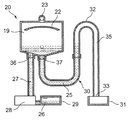
- FIG. 3 is a cross-sectional view schematically showing the configuration of the steam generator in the heating cooker according to the first embodiment of the present invention.
- FIG. 3 is intended only to show the connection relationship of the main elements in the steam generator in Embodiment 1, and the shape and size (capacity) of each element corresponds to the actual one. It is not a thing.
- a partition plate 22 having a substantially arc shape with a vertical cross-sectional shape projecting upward is provided, and the center of the concave surface on the lower surface side of the partition plate 22 is the center of the water storage chamber 19. It is arranged immediately below the center of the upper surface on the inner surface. Further, one steam generating heater 40 which is a linear sheathed heater having an output of 1000 W is provided below the partition plate 22 and below the water storage chamber 19.
- Embodiment 1 although it demonstrates by the example comprised using the linear heater of output 1000W as the steam generation heater 40 which is a heating part, as a steam generation heater, the shape of the water storage chamber 19, Depending on the required amount of steam in the specifications of the cooking device, the heater is provided with a desired output, and a plurality of heaters having the same output or different outputs may be provided. Good. Further, as the shape of the steam generating heater 40, various shapes of heaters other than the linear heater can be used in accordance with the shape of the water storage chamber 19, and for example, a U-shaped heater can be used. it can.
- the bottom surface of the inner surface of the water storage chamber 19 is composed of an inclined surface 24 having an inclination of about 20 ° with respect to a horizontal plane so that the central portion is the lowest end. That is, the bottom surface of the water storage chamber 19 is formed in a so-called funnel shape, and a drain port 37 is provided at the lowest point that is the central portion.
- a water supply port 36 for supplying water to the water storage chamber 19 is formed on the inclined surface 24 of the water storage chamber 19.
- the water supply port 36 is provided on the left side of the drainage port 37 in FIG. 3, and the water supply port 36 and the drainage port 37 are provided at different positions on the bottom surface of the water storage chamber 19.
- the inclination angle of the inclined surface 24 in the first embodiment is about 20 ° with respect to the horizontal plane, the flow of water varies depending on the shape of the water storage chamber 19, the amount of water during drainage, and the like. It is determined as appropriate according to the required water flow.
- one end of a water supply path 27 having an inner diameter ⁇ 6 made of semitransparent and elastic silicone is connected to the upstream side below the water supply port 36.
- the other end of the water supply passage 27 is connected to a water supply tank 29 via a water supply pump 28 which is a water supply device.
- a water supply pump 28 is used as a water supply device.
- an electric or manual valve is provided in a water supply channel using gravity and the valve is opened.
- a water supply means such as supplying water may be used as long as it can supply water into the water storage chamber 19.
- a drainage channel 30 in which the first drainage channel 25 and the second drainage channel 35 are continuous is provided on the downstream side below the drainage port 37.
- the first drainage channel 25 is translucent and formed of elastic silicone, and has a tubular shape with an inner diameter of ⁇ 6.
- the first drainage channel 25 is connected to the drainage port 37 without using a separate part such as a tube.
- the first drainage channel 25 extends downward (substantially in the vertical direction) from the drainage port 37, bends in a substantially horizontal direction at a predetermined length from the drainage port 37, and further And bent upward (substantially in the vertical direction). That is, the first drainage channel 25 has a so-called U-shape that protrudes downward.
- the 1st drainage channel 25 in Embodiment 1 although demonstrated in the example using silicone, fluorine, a polypropylene, polyethylene, etc. can also be used.
- a second drainage channel 35 formed by bending a copper pipe having an inner diameter ⁇ 6 is connected to the downstream side of the first drainage channel 25 without using a separate part such as a tube.
- the second drainage channel 35 extends upward from the joint portion with the first drainage channel 25 beyond the horizontal position of the steam generating heater 40.
- the second drainage channel 35 is bent 180 ° with the drainage channel apex 32 having the same height as the apex of the top surface on the inner surface of the water storage chamber 19 as the apex, and the downstream side of the drainage channel apex 32 is in the vertical direction. It extends downward. That is, the second drainage channel 35 has a so-called inverted U-shape that is convex upward.
- the second drainage channel 35 formed in this way is configured to flow the water flowing from the first drainage channel 25 to the drainage tank 31 through the drainage channel outlet 33.
- the drainage channel outlet 33 of the second drainage channel 35 is provided at a position below the bottom surface of the water storage chamber 19.
- the second drainage channel 35 has been described with a configuration using a copper pipe, but a pipe made of a material such as aluminum or iron can also be used.
- the water supply tank 29 is composed of two parts, a container part and a lid part, each of which is made of AS resin, which is a transparent amorphous plastic.
- the container portion and the lid portion of the water supply tank 29 are sealed so that water does not leak through a packing (not shown).
- a drain line 26 and a full water line 38 are displayed by silk printing.
- the water storage chamber 19, the water supply tank 29, and the drainage tank 31 shown in FIG. 3 do not show actual relative capacities, and the water storage chamber 19 has an exaggerated capacity compared to the water supply tank 29 and the drainage tank 31. It shows.
- the drainage line 26 and the full water line 38 have been described using silk printing.
- the present invention is not limited to such silk printing, and the water supply tank 29 is engraved or the water supply tank 29 is marked. An uneven portion may be provided and displayed.
- the microwave heating mode when the microwave heating mode is selected by the user and the start switch is turned on, the microwave is emitted from the magnetron 6.
- the microwave emitted from the magnetron 6 propagates in the waveguide 14 and irradiates the rotating antenna 11.
- the microwave is supplied into the heating chamber 1 while being stirred by the rotating antenna 11 rotated by the motor 18.
- the microwave supplied into the heating chamber 1 may be directly absorbed by the food 5 that is the object to be heated, while the microwave is absorbed by the food 5 while reflecting the wall surface of the heating chamber 1, and the food 5 is heated.
- the placing plate 4 is removed from the inside of the heating chamber 1, and the food 5 is placed on the placing table 3 and heated.
- the heating chamber heater 2 or the convection heater 8 is energized to generate heat, and the circulation fan 7 allows the inside of the heating chamber 1 to be heated. Hot air circulates and the food 5 is heated.
- the microwave is supplied into the heating chamber 1 as in the microwave heating mode.
- the heating element on the back surface of the mounting tray 4 generates heat.
- the heat of the heat generating element that has generated heat causes the entire mounting tray 4 to become a high temperature due to heat conduction, and the food 5 is heated from below.
- the microwaves wrap around the gap between the mounting plate 4 and the wall surface of the heating chamber 1 to heat the food 5.
- the heating chamber heater 2 is energized to generate heat, and the food 5 is heated from above by its radiant heat.
- the heating by the heating chamber heater 2 and the radiant heating by the heating chamber heater 2 are performed simultaneously with the heating by the microwave and the heating by the microwave or the radiant heating by the heating chamber heater 2 according to the setting contents by the user.
- the case of performing in is automatically selected.
- the steam heating mode is selected and the start switch is turned on
- the steam generating heater 40 in the water storage chamber 19 is energized to generate heat.
- the water storage chamber thermistor 34 provided in the water storage chamber 19 detects the temperature of the water storage chamber 19.
- the water in the water supply tank 29 is supplied to the water storage chamber 19 by the water supply pump 28 through the water supply path 27 and the water supply port 36.
- the water supply operation of the water supply pump 28 is stopped, and the supplied water is heated by the steam generating heater 40 and evaporated.
- the steam generated in the water storage chamber 19 (evaporation chamber) is discharged into the heating chamber 1 from the steam outlet 21 through the steam introduction path 23 and heats the food 5 that is the object to be heated.
- the vertical cross-sectional shape of the partition plate 22 is an arc shape with a convex upward, so that water droplets adhering to the lower surface of the partition plate 22 follow the arc surface. It is easy to fall down.
- water is replenished to the full water line 38 of the water supply tank 29, but steam heating is possible without replenishing water to the full water line 38.
- the control unit 10 outputs a water supply command to the water supply pump 28, Supply water automatically.
- the temperature of the water storage chamber thermistor 34 will fall.
- the evaporation in the water storage chamber 19 is continued, and the next water supply is not performed until the water level in the water storage chamber 19 falls and the temperature rises.
- the water level in the water storage chamber 19 can be kept within a predetermined range, and the water level can be easily detected and water can be automatically supplied without a water level sensor. If the temperature of the water storage chamber 19 does not stop even after the water supply command is output to the water supply pump 28, the control unit determines that the water in the water supply tank 29 has run out, ends the steam heating, A sound (warning sound) is emitted and displayed on the operation display unit 39 so as to inject water into the water supply tank 29 to notify the user.
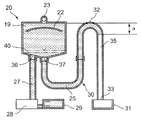
- FIG. 4A, FIG. 4B, FIG. 4C and FIG. 4D are cross-sectional views illustrating a drainage process based on the principle of siphon in the steam generator 20 of Embodiment 1 according to the present invention.
- FIG. 4A is a cross-sectional view showing a first operation (steam heating operation) in the steam generator of Embodiment 1.
- FIG. 4A during normal heating, water is stored by the water supply from the water supply pump 28 up to the water level above the steam generating heater 40 in the water storage chamber 19, and at the same time, the water level in the drainage channel 30 also rises.
- the water level in the water storage chamber 19 and the water level in the drainage channel 30 are the same.
- steam when steam is generated in the water storage chamber 19, the water level in the water storage chamber 19 and the water level in the drainage channel 30 are not the same because the pressure in the water storage chamber 19 increases and the water level in the drainage channel 30 increases.
- FIG. 4B shows a second operation in the steam generator during the drainage process according to the siphon principle in the first embodiment.
- the water supply pump 28 is automatically operated to supply water until the water level in the water storage chamber 19 reaches the drainage channel apex 32 above the water level during normal heating. Do.
- the water level rises to the drainage channel apex 32 there is a height difference a between the water level in the water storage chamber 19 and the water level in the drainage channel 30.
- FIG. 4B when there is a height difference a between the water level in the water storage chamber 19 and the water level in the drainage channel 30, as shown in FIG. 4C, the inside of the water storage chamber 19 and the first drainage channel 25 by the siphon principle.
- the inner scale condensed water and the deposited scale flow toward the drainage tank 31 through the drainage port 37, the drainage channel 30, and the drainage channel outlet 33.
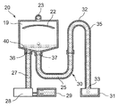
- FIG. 4C shows a third operation in the steam generator during the drainage process according to the siphon principle in the first embodiment.
- a difference in height a occurs between the water level in the water storage chamber 19 and the water level in the drainage channel 30, drainage begins.
- the driving time is set so that the water supply amount is slightly larger than the water supply amount necessary for drainage in consideration of the operation variation of the water supply pump 28.
- the detection means which detects the water level in the water storage chamber 19 at the time of drainage can be abbreviate
- FIG. 4D shows a fourth operation which is the final drainage operation in the steam generation apparatus during the drainage process according to the siphon principle in the first embodiment.
- the water in the water storage chamber 19 and the drainage channel 30 is emptied, and the drained water is stored in the drainage tank 31.
- the drainage tank 31 is taken out of the heating cooker by the user, and the water stored in the drainage tank 31 is discarded.
- the water in the water supply path 27 before and after the water supply pump 28 on the upstream side and the downstream side connected to the water supply pump 28 is not drained.
- the scale condensate and the deposited scale in the water storage chamber 19 and the first drainage channel 25 are discharged to the drainage tank 31.
- the scale deposited in the water storage chamber 19 during the generation of steam is guided below the water storage chamber 19 by the taper of the inclined surface 24 of the water storage chamber 19, and tends to settle and accumulate in the first drainage channel 25.
- the drainage channel is made of metal
- the scale is made of an inorganic substance such as calcium carbonate or magnesium carbonate, so it has a strong bond with the metal and can be used for a long time even when draining.
- the scale gradually adheres to the inside of the drainage channel and eventually drainage becomes impossible. As a result, there is a problem that the scale accumulates even in the water storage chamber and steam generation becomes impossible.
- the 1st drainage channel 25 of the drainage channel 30 is comprised with the silicone, the coupling
- the scale can be easily and reliably discharged from the first drainage channel 25 when drained according to the siphon principle.
- the microwave heating mode, the oven heating mode, the grill heating mode, and the steam heating mode can be operated independently, but each heating method is different. In combination, heating can be performed manually or automatically.
- FIG. 5A, FIG. 5B, FIG. 5C, and FIG. 5D are cross-sectional views illustrating the water drainage process of the water supply channel 27 in the steam generator according to Embodiment 1 of the present invention.
- FIG. 5A shows a first operation in the steam generator during the water drainage process of the water supply channel 27.
- FIG. 5B shows a second operation in the steam generator during the water drainage process of the water supply channel 27.
- FIG. 5C shows a third operation in the steam generator during the water drainage process of the water supply channel 27.
- FIG. 5D shows a fourth operation in the steam generator during the water drainage process of the water supply channel 27.
- the water in the water tank 29 is supplied to the water supply pump as shown in FIG. 5A. Water is supplied to the water storage chamber 19 by the water supply passage 27 and the water supply port 36. When the water supply is further continued, the water levels of the water storage chamber 19 and the drainage channel 30 reach the drainage channel apex 32 as shown in FIG. 5B. Since the water supply tank 29 stores only a capacity about 10 ml larger than the internal volume in the water storage chamber 19, the water in the water supply tank 29 almost disappears.
- the water supply pump 28 continues to operate even while the drainage tank 31 is drained.
- the water in the water supply tank 29 becomes empty, and the water supply pump 28 feeds air, not water, into the water supply path 27.
- the water supply pump 28 pushes the water in the water supply channel 27 into the water storage chamber 19 with air and drains it from the drainage channel 30.
- the feed pump 28 stops operating after a predetermined time has elapsed.
- the water pushed into the water storage chamber 19 joins the drainage by the siphon principle, and is drained toward the drainage tank 31 at the same time, and the water supply tank 29, the water supply channel 27, The water in the water storage chamber 19 and the drainage channel 30 is completely emptied.
- the drainage line 26 was provided in the water supply tank 29, 100 ml which is a required amount for drainage is displayed on the operation display part 39, and water is replenished to the user. You may get it.
- a cleaning agent such as citric acid is used instead of water, dirt such as scale and scale in the water storage chamber 19 can be easily removed, and a cleaner steam generator can be provided.
- the water storage chamber 19 that stores water
- the steam generation heater 40 that heats the water in the water storage chamber 19
- the water supply port 36 and the water supply channel 27 provided in the water storage chamber 19.
- a water supply pump 28 that feeds water from the water supply tank 29 and a drain outlet 37 provided in the water storage chamber 19, and a U-shaped first drainage channel 25 that protrudes downward, and an inverted U-shape that protrudes upward
- the second drainage channel 35 and a drainage channel 30 for draining are provided.
- the drainage channel 30 is disposed in the water storage chamber 19 via a position (drainage channel apex 32) above the water surface stored during normal heating.
- the water supply pump 28 is operated to push up the water level to the drainage channel apex 32 in the drainage channel 30, so that the water stored in the water storage chamber 19 by the siphon principle is drained from the drainage port 37, the drainage channel 30 and the drainage.
- the drainage tank 31 can be drained through the road outlet 33.
- at least the first drainage channel 25 in the drainage channel 30 is made of silicone.
- the first drainage channel 25 which is structurally easy to deposit and accumulate, is silicone, the first drainage channel 25 and the scale are weakly coupled, The scale does not adhere to the first drainage channel 25, and the scale can be reliably discharged when drained according to the siphon principle.
- the configuration of the first embodiment of the present invention it is possible to provide a steam generating device in which the steam generating performance is not deteriorated even if it is used for a long time.
- the non-metal part of at least the 1st drainage channel 25 in the drainage channel 30 is configured to be visible with a transparent member, and the user can easily determine the drainage state. By doing this, the user can open the door 42 in the heating cooker and visually check the scale of the first drainage channel 25 to drain the water. For this reason, when the steam generator 20 in Embodiment 1 uses water with low hardness etc., even if the scale does not accumulate in the drainage channel 30, waste such as performing the drainage operation is performed. When the drainage operation is necessary, drainage can be performed at an appropriate timing by the principle of siphon, and when the drainage operation is performed, the scale can be surely discharged. As a result, the steam generator 20 according to Embodiment 1 can provide a highly reliable steam generator in which the steam generation performance does not deteriorate even if the steam generator 20 is used for a long period of time.
- the first drainage channel 25 in the drainage channel 30 is made of a non-metal
- the second drainage channel 35 is made of a metal, so that scales are particularly easily accumulated.
- the scale does not stick to the first drainage channel 25, and the second drainage channel 35 can be easily fixed and inexpensively constructed by bending a metal pipe.
- the non-metal part of the 1st drainage channel 25 is comprised with an elastic body, the drain outlet 37 which connects the 1st drainage channel 25 and the water storage chamber 19, and the 1st drainage channel 25 and the 2nd
- the connecting portion with the drainage channel 35 can be configured without using a separate part such as a tube.
- the steam generator 20 in Embodiment 1 can prevent water leakage due to an increase in the number of parts, and can be configured with high reliability and low cost.
- the first drainage channel 25 made of metal for reasons of heat resistance, for example. Even when it is necessary to use the scale, it is possible to prevent the scale from adhering to the first drainage channel 25 with a simple configuration.
- the coating layer as described above on the inner surface of the non-metallic first drainage channel 25, the heat resistance and reliability can be further increased.
- one water storage chamber thermistor 34 is provided in the water storage chamber 19 and the water level of the water storage chamber 19 is simply estimated.
- a plurality of water storage chamber thermistors 34 are provided in the water storage chamber. Or by measuring the water level of the water storage chamber 19 or the drainage channel 30 using a water level sensor, the amount of water supply can be adjusted more accurately.
- a drainage tank detection device that detects whether or not the drainage tank 31 is mounted at a predetermined position, it is possible to configure so that at least the drainage process cannot be performed when the drainage tank 31 is forgotten to be attached. Thus, it is possible to prevent the water stored in the drainage channel 30 from flowing and spilling on the floor surface.
- the temperature of the water in the water storage chamber 19 can be lowered at the same time when water is supplied to perform drainage according to the siphon principle. Even if it moves to a drainage process, you may comprise so that it may discharge
- the temperature of the discharged water is preferably low, but the natural cooling time becomes longer as the drainage temperature is lowered. Therefore, the drainage temperature is appropriately set in consideration of the balance with the cooling time.
- the steam generator according to the present invention is a highly useful device that can be applied to various uses such as a microwave oven, an oven microwave oven, an electric oven, a rice cooker, and a commercial thawing device as a cooking utensil using steam. .
Abstract
Description
前記排水路は、前記貯水室に設けられた排水口に通じて下方に凸となるU字状の第1の排水路と、前記第1の排水路に連続して設けられ上方に凸となる逆U字状の第2の排水路とを有し、前記貯水室内で通常加熱時に貯められている水面の位置より上方の位置を排水路頂点とし、前記給水装置を動作させて前記排水路頂点まで水位を押し上げることによって、サイフォンの原理により前記貯水室に貯まっていた水を前記排水口と前記排水路とを通じて排水するよう構成されており、前記第1の排水路の少なくとも内面が非金属で構成されている。 The steam generator of the present invention includes a water storage chamber for storing water, a heating unit for heating the water in the water storage chamber, a water supply device for sending water from a water supply tank through a water supply port and a water supply path provided in the water storage chamber, A drainage channel for draining the water in the reservoir,
The drainage channel is provided with a U-shaped first drainage channel that protrudes downward through a drainage port provided in the water storage chamber, and is provided continuously with the first drainage channel and protrudes upward. An inverted U-shaped second drainage channel, and a position above the position of the water surface stored during normal heating in the reservoir is defined as a drainage channel apex, and the water supply device is operated to operate the drainage channel apex By pushing up the water level to the extent that the water stored in the water storage chamber is drained through the drain outlet and the drainage channel according to the principle of siphon, at least the inner surface of the first drainage channel is made of a non-metal. It is configured.
水を貯める貯水室、
前記貯水室内の水を加熱する加熱部、
前記貯水室に設けられた給水口および給水路を通じて給水タンクの水を送る給水装置、および
前記貯水室の水を排水する排水路、を備えており、
前記排水路は、前記貯水室に設けられた排水口に通じて下方に凸となるU字状の第1の排水路と、前記第1の排水路に連続して設けられ上方に凸となる逆U字状の第2の排水路とを有して構成されており、前記貯水室内で通常加熱時に貯められている水面の位置より上方の位置を排水路頂点とし、前記給水装置を動作させて前記排水路頂点まで水位を押し上げることによって、サイフォンの原理により前記貯水室に貯まっていた水を前記排水口と前記排水路とを通じて排水するよう構成されており、前記第1の排水路の少なくとも内面が非金属で構成されている。 The steam generator according to the first aspect of the present invention comprises:
A water reservoir for storing water,
A heating unit for heating water in the water storage chamber;
A water supply device that sends water from a water supply tank through a water supply port and a water supply channel provided in the water storage chamber, and a drainage channel that drains water from the water storage chamber,
The drainage channel is provided with a U-shaped first drainage channel that protrudes downward through a drainage port provided in the water storage chamber, and is provided continuously with the first drainage channel and protrudes upward. And an inverted U-shaped second drainage channel. The drainage channel apex is located above the position of the water surface stored during normal heating in the water storage chamber, and the water supply device is operated. By pushing up the water level to the top of the drainage channel, the water stored in the water storage chamber is drained through the drainage port and the drainage channel according to the principle of siphon, and at least of the first drainage channel. The inner surface is made of non-metal.
図1は、本発明に係る実施の形態1の蒸気発生装置を備えた加熱調理器の正面断面図を示す。 (Embodiment 1)
FIG. 1 shows a front cross-sectional view of a cooking device provided with the steam generator according to Embodiment 1 of the present invention.
また、載置皿4の表面はフッ素塗装され、裏面にはマイクロ波を吸収して発熱する発熱体が備えられている。このように、載置皿4の裏面に発熱体を備えることにより、食品5の上方に設けられた加熱室ヒータ2と、載置皿4の裏面の発熱体との組み合わせにより、食品5の両面を加熱することができる。なお、載置皿4とレール12との接触部分には加熱室1と絶縁するためにPPS樹脂の成型品が備えられている。 The mounting plate 4 is formed of an aluminum-plated steel plate, and is unevenly processed with a press so that the oil and fat from the
Moreover, the surface of the mounting tray 4 is coated with fluorine, and the back surface is provided with a heating element that absorbs microwaves and generates heat. Thus, by providing a heating element on the back surface of the mounting dish 4, the both sides of the
20 蒸気発生装置
25 第1の排水路
27 給水路
28 給水ポンプ
29 給水タンク
30 排水路
32 排水路頂点
35 第2の排水路
36 給水口
37 排水口
40 蒸気発生ヒータ DESCRIPTION OF
Claims (7)
- 水を貯める貯水室と、
前記貯水室内の水を加熱する加熱部と、
前記貯水室に設けられた給水口および給水路を通じて給水タンクの水を送る給水装置と、
前記貯水室の水を排水する排水路と、を備えており、
前記排水路は、前記貯水室に設けられた排水口に通じて下方に凸となるU字状の第1の排水路と、前記第1の排水路に連続して設けられ上方に凸となる逆U字状の第2の排水路とを有して、前記貯水室内で通常加熱時に貯められている水面の位置より上方の位置を排水路頂点とし、前記給水装置を動作させて前記排水路頂点まで水位を押し上げることによって、サイフォンの原理により前記貯水室に貯まっていた水を前記排水口と前記排水路とを通じて排水するよう構成されており、前記第1の排水路の少なくとも内面が非金属で構成された蒸気発生装置。 A reservoir for storing water,
A heating unit for heating water in the water storage chamber;
A water supply device for supplying water from a water supply tank through a water supply port and a water supply passage provided in the water storage chamber;
A drainage channel for draining the water in the reservoir,
The drainage channel is provided with a U-shaped first drainage channel that protrudes downward through a drainage port provided in the water storage chamber, and is provided continuously with the first drainage channel and protrudes upward. An inverted U-shaped second drainage channel, and the drainage channel apex is a position above the position of the water surface stored during normal heating in the reservoir, and the water supply device is operated to operate the drainage channel. By pushing up the water level to the top, the water stored in the water storage chamber is drained through the drainage port and the drainage channel according to the principle of siphon, and at least the inner surface of the first drainage channel is non-metallic. A steam generator composed of - 前記排水路における少なくとも前記第1の排水路が非金属で構成された請求項1に記載の蒸気発生装置。 The steam generator according to claim 1, wherein at least the first drainage channel in the drainage channel is made of a non-metal.
- 前記排水路における少なくとも前記第1の排水路が非金属で構成され、前記第1の排水路の内部状態が目視可能となるように、前記第1の排水路が透明部材により構成された請求項2に記載の蒸気発生装置。 The at least 1st drainage channel in the said drainage channel is comprised with the nonmetal, The said 1st drainage channel was comprised with the transparent member so that the internal state of the said 1st drainage channel became visible. 2. The steam generator according to 2.
- 前記第2の排水路が金属で構成された請求項1から3のいずれか1項に記載の蒸気発生装置。 The steam generator according to any one of claims 1 to 3, wherein the second drainage channel is made of metal.
- 前記排水路における少なくとも前記第1の排水路が非金属で構成され、前記第1の排水路が弾性体により構成された請求項1から4のいずれか1項に記載の蒸気発生装置。 The steam generator according to any one of claims 1 to 4, wherein at least the first drainage channel in the drainage channel is made of a non-metal, and the first drainage channel is made of an elastic body.
- 前記第1の排水路の内面に非金属のコーティング層が形成された請求項1から5のいずれか1項に記載の蒸気発生装置。 The steam generator according to any one of claims 1 to 5, wherein a non-metallic coating layer is formed on an inner surface of the first drainage channel.
- 請求項1から6のいずれか1項に記載の蒸気発生装置を備えた加熱調理器。 A heating cooker provided with the steam generator according to any one of claims 1 to 6.
Priority Applications (4)
| Application Number | Priority Date | Filing Date | Title |
|---|---|---|---|
| US14/384,623 US9841182B2 (en) | 2012-03-15 | 2013-03-12 | Steam generator and heating cooker comprising steam generator |
| CN201380025305.1A CN104285098A (en) | 2012-03-15 | 2013-03-12 | Steam generator and heating cooker comprising steam generator |
| JP2014504698A JP6074724B2 (en) | 2012-03-15 | 2013-03-12 | Steam generator and cooking device provided with steam generator |
| EP13760497.1A EP2827057B1 (en) | 2012-03-15 | 2013-03-12 | Steam generator and heating cooker comprising steam generator |
Applications Claiming Priority (2)
| Application Number | Priority Date | Filing Date | Title |
|---|---|---|---|
| JP2012058282 | 2012-03-15 | ||
| JP2012-058282 | 2012-03-15 |
Publications (1)
| Publication Number | Publication Date |
|---|---|
| WO2013136773A1 true WO2013136773A1 (en) | 2013-09-19 |
Family
ID=49160702
Family Applications (1)
| Application Number | Title | Priority Date | Filing Date |
|---|---|---|---|
| PCT/JP2013/001608 WO2013136773A1 (en) | 2012-03-15 | 2013-03-12 | Steam generator and heating cooker comprising steam generator |
Country Status (5)
| Country | Link |
|---|---|
| US (1) | US9841182B2 (en) |
| EP (1) | EP2827057B1 (en) |
| JP (1) | JP6074724B2 (en) |
| CN (1) | CN104285098A (en) |
| WO (1) | WO2013136773A1 (en) |
Cited By (1)
| Publication number | Priority date | Publication date | Assignee | Title |
|---|---|---|---|---|
| WO2015198855A1 (en) * | 2014-06-27 | 2015-12-30 | シャープ株式会社 | Steam generating device and thermal cooking apparatus |
Families Citing this family (14)
| Publication number | Priority date | Publication date | Assignee | Title |
|---|---|---|---|---|
| KR102252918B1 (en) * | 2014-11-27 | 2021-05-18 | 엘지전자 주식회사 | Steam generator and Cooker including the same |
| US10357126B2 (en) * | 2015-03-25 | 2019-07-23 | Illinois Tool Works Inc. | Steam generator |
| US10973360B2 (en) | 2015-03-25 | 2021-04-13 | Illinois Tool Works Inc. | Steam generator |
| CN105864738A (en) * | 2016-05-06 | 2016-08-17 | 广东长盈电器有限公司 | Limescale-free vapor generator |
| CN105747885B (en) * | 2016-05-19 | 2018-05-29 | 广东恒基卓越电器科技有限公司 | Automatic water-supply formula water tank |
| MY188110A (en) * | 2016-08-17 | 2021-11-20 | Yasar M B Al Atheri | Multi-purpose self-sustained heat generating revolving evaporator apparatus (msre) |
| DE102016215650A1 (en) * | 2016-08-19 | 2018-02-22 | BSH Hausgeräte GmbH | Haushaltsgargerät |
| CN106580111B (en) * | 2016-12-29 | 2023-09-15 | 宁波方太厨具有限公司 | Water tank and steaming cooking equipment using same |
| KR101975196B1 (en) * | 2017-05-17 | 2019-05-07 | 엘지전자 주식회사 | Cooking apparatus |
| CN107007133B (en) * | 2017-06-01 | 2022-07-22 | 杭州向田科技有限公司 | Cooking method of wooden barrel rice cooker |
| DE102019203637A1 (en) * | 2019-03-18 | 2020-09-24 | BSH Hausgeräte GmbH | Cooking device with a water line of a steam generating device formed with non-stick material and / or a polishing surface |
| US20200323245A1 (en) * | 2019-04-15 | 2020-10-15 | Fishsix Rc The Melt | Controlling temperature and humidity in a food transportation system |
| KR20210073939A (en) * | 2019-12-11 | 2021-06-21 | 삼성전자주식회사 | Clothes Care Device and Control Method thereof |
| CN111297210A (en) * | 2020-02-24 | 2020-06-19 | 九阳股份有限公司 | Scale cleaning method for steam heating type cooking utensil |
Citations (4)
| Publication number | Priority date | Publication date | Assignee | Title |
|---|---|---|---|---|
| JPH01169204A (en) * | 1987-12-25 | 1989-07-04 | Matsushita Electric Ind Co Ltd | Steam generator |
| JPH10267210A (en) * | 1997-03-27 | 1998-10-09 | Matsushita Electric Ind Co Ltd | Steam generator |
| JP2005083708A (en) * | 2003-09-10 | 2005-03-31 | Sharp Corp | Steam generator and heating cooker with steam generator |
| JP2010054096A (en) | 2008-08-27 | 2010-03-11 | Sharp Corp | Liquid supply/discharge device, steam generator using the same, cleaning method of liquid supply/discharge device, and cleaning method of steam generator |
Family Cites Families (11)
| Publication number | Priority date | Publication date | Assignee | Title |
|---|---|---|---|---|
| DE8901904U1 (en) * | 1989-02-17 | 1989-07-20 | Lechmetall Landsberg Gmbh, 8910 Landsberg, De | |
| CN2355254Y (en) | 1998-05-26 | 1999-12-22 | 王家君 | Anti-scaling electric water heater |
| JP2002130990A (en) | 2000-10-26 | 2002-05-09 | Toto Ltd | Scale formation preventing component coming in contact with water in boiler and manufacturing method thereof |
| US7326893B2 (en) | 2003-05-20 | 2008-02-05 | Matsushita Electric Industrial Co., Ltd. | High frequency heating apparatus having steam generating function |
| JP3835804B2 (en) * | 2004-02-10 | 2006-10-18 | 松下電器産業株式会社 | Cooking device and cooking method |
| JP3795050B2 (en) * | 2004-03-22 | 2006-07-12 | シャープ株式会社 | Steam cooker |
| CN100520213C (en) | 2006-04-25 | 2009-07-29 | 黄樟焱 | Energy-saving instantaneously-heated type electric heater unit |
| GB0722934D0 (en) * | 2007-05-16 | 2008-01-02 | Otter Controls Ltd | Electrical appliances |
| CN201137919Y (en) | 2007-08-08 | 2008-10-22 | 徐建刚 | Descaling water heater |
| JP4586111B1 (en) * | 2009-04-16 | 2010-11-24 | シャープ株式会社 | Cooker |
| WO2012140003A1 (en) * | 2011-04-15 | 2012-10-18 | BSH Bosch und Siemens Hausgeräte GmbH | Steam cooking appliance, in particular a steam oven |
-
2013
- 2013-03-12 JP JP2014504698A patent/JP6074724B2/en active Active
- 2013-03-12 WO PCT/JP2013/001608 patent/WO2013136773A1/en active Application Filing
- 2013-03-12 EP EP13760497.1A patent/EP2827057B1/en active Active
- 2013-03-12 US US14/384,623 patent/US9841182B2/en active Active
- 2013-03-12 CN CN201380025305.1A patent/CN104285098A/en active Pending
Patent Citations (4)
| Publication number | Priority date | Publication date | Assignee | Title |
|---|---|---|---|---|
| JPH01169204A (en) * | 1987-12-25 | 1989-07-04 | Matsushita Electric Ind Co Ltd | Steam generator |
| JPH10267210A (en) * | 1997-03-27 | 1998-10-09 | Matsushita Electric Ind Co Ltd | Steam generator |
| JP2005083708A (en) * | 2003-09-10 | 2005-03-31 | Sharp Corp | Steam generator and heating cooker with steam generator |
| JP2010054096A (en) | 2008-08-27 | 2010-03-11 | Sharp Corp | Liquid supply/discharge device, steam generator using the same, cleaning method of liquid supply/discharge device, and cleaning method of steam generator |
Cited By (2)
| Publication number | Priority date | Publication date | Assignee | Title |
|---|---|---|---|---|
| WO2015198855A1 (en) * | 2014-06-27 | 2015-12-30 | シャープ株式会社 | Steam generating device and thermal cooking apparatus |
| JP2016011776A (en) * | 2014-06-27 | 2016-01-21 | シャープ株式会社 | Steam generating device and thermal cooking apparatus |
Also Published As
| Publication number | Publication date |
|---|---|
| EP2827057A1 (en) | 2015-01-21 |
| EP2827057B1 (en) | 2019-05-08 |
| CN104285098A (en) | 2015-01-14 |
| US20150083110A1 (en) | 2015-03-26 |
| JPWO2013136773A1 (en) | 2015-08-03 |
| EP2827057A4 (en) | 2015-08-12 |
| US9841182B2 (en) | 2017-12-12 |
| JP6074724B2 (en) | 2017-02-08 |
Similar Documents
| Publication | Publication Date | Title |
|---|---|---|
| JP6074724B2 (en) | Steam generator and cooking device provided with steam generator | |
| JP6029032B2 (en) | Steam generator and cooking device provided with steam generator | |
| WO2014181502A1 (en) | Steam-generating device | |
| WO2014141712A1 (en) | Vapor generation device | |
| WO2014141714A1 (en) | Vapor generation device | |
| WO2014141713A1 (en) | Vapor generation device | |
| JP5919490B2 (en) | Steam generator and cooking device equipped with the same | |
| JP2014020705A (en) | Steam generator | |
| JP2013119951A (en) | Heating cooker |
Legal Events
| Date | Code | Title | Description |
|---|---|---|---|
| 121 | Ep: the epo has been informed by wipo that ep was designated in this application |
Ref document number: 13760497 Country of ref document: EP Kind code of ref document: A1 |
|
| DPE2 | Request for preliminary examination filed before expiration of 19th month from priority date (pct application filed from 20040101) | ||
| ENP | Entry into the national phase |
Ref document number: 2014504698 Country of ref document: JP Kind code of ref document: A |
|
| WWE | Wipo information: entry into national phase |
Ref document number: 14384623 Country of ref document: US Ref document number: 2013760497 Country of ref document: EP |
|
| NENP | Non-entry into the national phase |
Ref country code: DE |