JP6029032B2 - Steam generator and cooking device provided with steam generator - Google Patents

Steam generator and cooking device provided with steam generator Download PDF

Info

Publication number
JP6029032B2
JP6029032B2 JP2014525709A JP2014525709A JP6029032B2 JP 6029032 B2 JP6029032 B2 JP 6029032B2 JP 2014525709 A JP2014525709 A JP 2014525709A JP 2014525709 A JP2014525709 A JP 2014525709A JP 6029032 B2 JP6029032 B2 JP 6029032B2
Authority
JP
Japan
Prior art keywords
water
storage chamber
steam
water storage
heating
Prior art date
Legal status (The legal status is an assumption and is not a legal conclusion. Google has not performed a legal analysis and makes no representation as to the accuracy of the status listed.)
Active
Application number
JP2014525709A
Other languages
Japanese (ja)
Other versions
JPWO2014013700A1 (en
Inventor
澁谷 昌樹
昌樹 澁谷
河合 祐
祐 河合
早川 雄二
雄二 早川
邦昭 阿部
邦昭 阿部
Current Assignee (The listed assignees may be inaccurate. Google has not performed a legal analysis and makes no representation or warranty as to the accuracy of the list.)
Panasonic Intellectual Property Management Co Ltd
Original Assignee
Panasonic Intellectual Property Management Co Ltd
Priority date (The priority date is an assumption and is not a legal conclusion. Google has not performed a legal analysis and makes no representation as to the accuracy of the date listed.)
Filing date
Publication date
Application filed by Panasonic Intellectual Property Management Co Ltd filed Critical Panasonic Intellectual Property Management Co Ltd
Publication of JPWO2014013700A1 publication Critical patent/JPWO2014013700A1/en
Application granted granted Critical
Publication of JP6029032B2 publication Critical patent/JP6029032B2/en
Active legal-status Critical Current
Anticipated expiration legal-status Critical

Links

Images

Classifications

    • AHUMAN NECESSITIES
    • A47FURNITURE; DOMESTIC ARTICLES OR APPLIANCES; COFFEE MILLS; SPICE MILLS; SUCTION CLEANERS IN GENERAL
    • A47JKITCHEN EQUIPMENT; COFFEE MILLS; SPICE MILLS; APPARATUS FOR MAKING BEVERAGES
    • A47J27/00Cooking-vessels
    • A47J27/04Cooking-vessels for cooking food in steam; Devices for extracting fruit juice by means of steam ; Vacuum cooking vessels
    • AHUMAN NECESSITIES
    • A47FURNITURE; DOMESTIC ARTICLES OR APPLIANCES; COFFEE MILLS; SPICE MILLS; SUCTION CLEANERS IN GENERAL
    • A47JKITCHEN EQUIPMENT; COFFEE MILLS; SPICE MILLS; APPARATUS FOR MAKING BEVERAGES
    • A47J36/00Parts, details or accessories of cooking-vessels
    • A47J36/02Selection of specific materials, e.g. heavy bottoms with copper inlay or with insulating inlay
    • A47J36/027Cooking- or baking-vessels specially adapted for use in microwave ovens; Accessories therefor
    • FMECHANICAL ENGINEERING; LIGHTING; HEATING; WEAPONS; BLASTING
    • F22STEAM GENERATION
    • F22BMETHODS OF STEAM GENERATION; STEAM BOILERS
    • F22B1/00Methods of steam generation characterised by form of heating method
    • F22B1/28Methods of steam generation characterised by form of heating method in boilers heated electrically
    • F22B1/281Methods of steam generation characterised by form of heating method in boilers heated electrically other than by electrical resistances or electrodes
    • FMECHANICAL ENGINEERING; LIGHTING; HEATING; WEAPONS; BLASTING
    • F22STEAM GENERATION
    • F22BMETHODS OF STEAM GENERATION; STEAM BOILERS
    • F22B1/00Methods of steam generation characterised by form of heating method
    • F22B1/28Methods of steam generation characterised by form of heating method in boilers heated electrically
    • F22B1/284Methods of steam generation characterised by form of heating method in boilers heated electrically with water in reservoirs
    • F22B1/285Methods of steam generation characterised by form of heating method in boilers heated electrically with water in reservoirs the water being fed by a pump to the reservoirs
    • FMECHANICAL ENGINEERING; LIGHTING; HEATING; WEAPONS; BLASTING
    • F24HEATING; RANGES; VENTILATING
    • F24CDOMESTIC STOVES OR RANGES ; DETAILS OF DOMESTIC STOVES OR RANGES, OF GENERAL APPLICATION
    • F24C15/00Details
    • F24C15/32Arrangements of ducts for hot gases, e.g. in or around baking ovens
    • F24C15/322Arrangements of ducts for hot gases, e.g. in or around baking ovens with forced circulation
    • F24C15/327Arrangements of ducts for hot gases, e.g. in or around baking ovens with forced circulation with air moisturising
    • HELECTRICITY
    • H05ELECTRIC TECHNIQUES NOT OTHERWISE PROVIDED FOR
    • H05BELECTRIC HEATING; ELECTRIC LIGHT SOURCES NOT OTHERWISE PROVIDED FOR; CIRCUIT ARRANGEMENTS FOR ELECTRIC LIGHT SOURCES, IN GENERAL
    • H05B6/00Heating by electric, magnetic or electromagnetic fields
    • H05B6/64Heating using microwaves
    • H05B6/80Apparatus for specific applications
    • H05B6/802Apparatus for specific applications for heating fluids
    • H05B6/804Water heaters, water boilers
    • AHUMAN NECESSITIES
    • A47FURNITURE; DOMESTIC ARTICLES OR APPLIANCES; COFFEE MILLS; SPICE MILLS; SUCTION CLEANERS IN GENERAL
    • A47JKITCHEN EQUIPMENT; COFFEE MILLS; SPICE MILLS; APPARATUS FOR MAKING BEVERAGES
    • A47J27/00Cooking-vessels
    • A47J27/04Cooking-vessels for cooking food in steam; Devices for extracting fruit juice by means of steam ; Vacuum cooking vessels
    • A47J2027/043Cooking-vessels for cooking food in steam; Devices for extracting fruit juice by means of steam ; Vacuum cooking vessels for cooking food in steam

Description

本発明は、水を加熱して蒸気を発生させる蒸気発生装置及びその蒸気発生装置を備えた加熱調理器に関するものである。   The present invention relates to a steam generator that heats water to generate steam and a heating cooker including the steam generator.

従来、蒸気発生装置として、蒸気発生室の内部に迷路状の通路が形成されるように、放熱フィンを配置したものがある(例えば、特許文献1参照)。このように放熱フィンを配置することにより、蒸気発生室の底部から沸騰水が駆け上がり、蒸気吹出口に至ることを防止しようとしている。特許文献1の蒸気発生装置では、特に、沸騰水の駆け上がりの防止を目的として、放熱フィンに水平方向に延びる平状板部分を設けている。   Conventionally, as a steam generator, there is one in which heat radiation fins are arranged so that a labyrinth-shaped passage is formed inside a steam generation chamber (for example, see Patent Document 1). By arranging the heat dissipating fins in this way, it is intended to prevent boiling water from running from the bottom of the steam generation chamber and reaching the steam outlet. In the steam generator of patent document 1, the flat plate part extended in a horizontal direction is provided in the radiation fin especially in order to prevent the run-up of boiling water.

特開2008−164284号公報JP 2008-164284 A

しかしながら、前記の従来の構成では、沸騰水の駆け上がりを完全には防ぐことができない。昨今では、沸騰水の駆け上がりをより確実に防止することが望まれている。   However, the conventional configuration cannot completely prevent boiling water from running up. Nowadays, it is desired to more reliably prevent boiling water from running up.

本発明は、前記従来の課題を解決するもので、蒸気発生室内の沸騰水の駆け上がりを少なくすることにより、沸騰水が蒸気噴出口から噴出することを防ぐことができる蒸気発生装置を提供することを目的とする。   This invention solves the said conventional subject, and provides the steam generator which can prevent that boiling water spouts from a steam outlet by reducing the run-up of the boiling water in a steam generation chamber. For the purpose.

蒸気発生装置は、水を貯める貯水室と、前記貯水室内の水を加熱して蒸気を発生させる少なくとも1つの加熱部と、前記貯水室内に水を給水する給水装置と、前記貯水室内に設けられた複数のフィンとを備え、前記貯水室には、前記加熱部によって発生された蒸気を噴出する蒸気噴出口が設けられており、前記蒸気噴出口の下方において、前記複数のフィンは、蒸気発生方向に沿って形成されるとともに、前記加熱部を横切るように互いに離間して配置される。   The steam generator is provided in a water storage chamber for storing water, at least one heating unit for heating the water in the water storage chamber to generate steam, a water supply device for supplying water to the water storage chamber, and the water storage chamber. A plurality of fins, and the water storage chamber is provided with a steam outlet for ejecting the steam generated by the heating unit, and the plurality of fins generate steam under the steam outlet. While being formed along the direction, they are spaced apart from each other so as to cross the heating section.

このような蒸気発生装置によれば、特に、蒸気噴出口の下方において、蒸気発生方向に沿って形成されるとともに、加熱部を横切るように互いに離間して配置された複数のフィンが設けられている。よって、特に温度の高い加熱部付近の熱が、熱の伝わりにくい貯水室内の水の内部にまでフィンによって伝わり、また、フィンにより貯水室と水との接触面積が増えるため、加熱部からの熱を効率的に水に伝えることができる。これにより、貯水室と水とが接触する部分の温度が下がり、温度の高い部分で発生しうる大きな気泡が少なくなる。よって、大きな気泡が水面に上昇して破裂することによる沸騰水の駆け上がりを少なくし、沸騰水が蒸気噴出口から噴出することを防ぐことができる。また、大きな気泡の発生を少なくすることで、気泡の破裂音を抑えることができる。   According to such a steam generator, a plurality of fins that are formed along the steam generation direction and spaced apart from each other so as to cross the heating portion are provided, particularly under the steam outlet. Yes. Therefore, the heat in the vicinity of the heating section, which has a particularly high temperature, is transmitted to the inside of the water in the water storage room where heat is difficult to transfer, and the contact area between the water storage room and the water is increased by the fin. Can be efficiently transmitted to water. As a result, the temperature of the portion where the water storage chamber and water are in contact with each other is lowered, and large bubbles that can be generated in the high temperature portion are reduced. Therefore, the run-up of the boiling water due to the large bubbles rising to the water surface and bursting can be reduced, and the boiling water can be prevented from being ejected from the steam outlet. Further, by reducing the generation of large bubbles, it is possible to suppress the burst sound of the bubbles.

また、蒸気発生装置は、水を貯める貯水室と、前記貯水室内の水を加熱して蒸気を発生させる加熱部と、前記貯水室内に水を給水する給水装置とを備え、前記貯水室には、前記加熱部によって発生された蒸気を噴出する蒸気噴出口が設けられており、前記加熱部は、加熱時における貯水室内の水面の上側と下側に少なくとも1つずつ設けられても良い。   The steam generator includes a water storage chamber for storing water, a heating unit for heating the water in the water storage chamber to generate steam, and a water supply device for supplying water to the water storage chamber, In addition, steam outlets for ejecting steam generated by the heating unit may be provided, and at least one heating unit may be provided on the upper and lower sides of the water surface in the water storage chamber during heating.

このような蒸気発生装置によれば、沸騰時に発生する気泡が水面で破裂して駆け上がろうとしても、水面の上側にある加熱部によって加熱されて蒸気になるため、沸騰水が蒸気噴出口から噴出することを防ぐことができる。   According to such a steam generator, even if bubbles generated at the time of boiling burst on the water surface and try to run up, the water is heated by the heating unit above the water surface to become steam. Can be prevented from being ejected from.

本発明の蒸気発生装置は、蒸気発生室内の沸騰水の駆け上がりを少なくすることにより、沸騰水が蒸気噴出口から噴出することを防ぐことができる。   The steam generator of the present invention can prevent boiling water from being ejected from the steam outlet by reducing the running up of boiling water in the steam generating chamber.

本発明に係る実施の形態1の蒸気発生装置を備えた加熱調理器の正面断面図Front sectional drawing of the cooking-by-heating machine provided with the steam generator of Embodiment 1 which concerns on this invention. 本発明に係る実施の形態1の蒸気発生装置を備えた加熱調理器の外観を示す斜視図The perspective view which shows the external appearance of the heating cooker provided with the steam generator of Embodiment 1 which concerns on this invention. 本発明に係る実施の形態1の蒸気発生装置を模式的に示す縦断面図1 is a longitudinal sectional view schematically showing a steam generator according to Embodiment 1 of the present invention. 本発明に係る実施の形態1の蒸気発生装置を模式的に示す横断面図1 is a cross-sectional view schematically showing a steam generator according to Embodiment 1 of the present invention. 本発明に係る実施の形態1の蒸気発生装置におけるスチーム加熱モードのフローチャートFlowchart of the steam heating mode in the steam generator according to Embodiment 1 of the present invention 本発明に係る実施の形態1の蒸気発生装置が備える貯水室サーミスタの温度と時間の関係を示すグラフThe graph which shows the relationship between the temperature of the water storage chamber thermistor with which the steam generator of Embodiment 1 which concerns on this invention is equipped, and time 本発明に係る実施の形態1におけるサイフォンの原理による排水工程時の蒸気発生装置における第1の動作を示す断面図Sectional drawing which shows the 1st operation | movement in the steam generator at the time of the drainage process by the principle of the siphon in Embodiment 1 which concerns on this invention. 本発明に係る実施の形態1におけるサイフォンの原理による排水工程時の蒸気発生装置における第2の動作を示す断面図Sectional drawing which shows the 2nd operation | movement in the steam generator at the time of the drainage process by the principle of the siphon in Embodiment 1 which concerns on this invention. 本発明に係る実施の形態1におけるサイフォンの原理による排水工程時の蒸気発生装置における第3の動作を示す断面図Sectional drawing which shows the 3rd operation | movement in the steam generator at the time of the drainage process by the principle of the siphon in Embodiment 1 which concerns on this invention. 本発明に係る実施の形態1におけるサイフォンの原理による排水工程時の蒸気発生装置における第4の動作を示す断面図Sectional drawing which shows the 4th operation | movement in the steam generator at the time of the drainage process by the principle of the siphon in Embodiment 1 which concerns on this invention. 本発明に係る実施の形態1における給水路の水の排水工程時の蒸気発生装置における第1の動作を示す断面図Sectional drawing which shows the 1st operation | movement in the steam generator at the time of the water drainage process of the water supply channel in Embodiment 1 which concerns on this invention. 本発明に係る実施の形態1における給水路の水の排水工程時の蒸気発生装置における第2の動作を示す断面図Sectional drawing which shows the 2nd operation | movement in the steam generator at the time of the water drainage process of the water supply channel in Embodiment 1 which concerns on this invention. 本発明に係る実施の形態1における給水路の水の排水工程時の蒸気発生装置における第3の動作を示す断面図Sectional drawing which shows the 3rd operation | movement in the steam generator at the time of the water drainage process of the water supply channel in Embodiment 1 which concerns on this invention. 本発明に係る実施の形態1における給水路の水の排水工程時の蒸気発生装置における第4の動作を示す断面図Sectional drawing which shows the 4th operation | movement in the steam generator at the time of the water drainage process of the water supply channel in Embodiment 1 which concerns on this invention.

第1の発明は、水を貯める貯水室と、前記貯水室内の水を加熱して蒸気を発生させる少なくとも1つの加熱部と、前記貯水室内に水を給水する給水装置と、前記貯水室内に設けられた複数のフィンとを備え、前記貯水室には、前記加熱部によって発生された蒸気を噴出する蒸気噴出口が設けられており、前記蒸気噴出口の下方において、前記複数のフィンは、蒸気発生方向に沿って形成されるとともに、前記加熱部を横切るように互いに離間して配置される、蒸気発生装置である。これにより、特に温度の高い加熱部付近の熱が、熱の伝わりにくい貯水室内の水の内部にまでフィンによって伝わり、また、フィンにより貯水室と水との接触面積が増えるため、加熱部からの熱を効率的に水に伝えることができる。これにより、貯水室と水とが接触する部分の温度が下がり、温度の高い部分で発生しうる大きな気泡が少なくなる。よって、大きな気泡が水面に上昇して破裂することによる沸騰水の駆け上がりを少なくし、沸騰水が蒸気噴出口から噴出することを防ぐことができる。また、大きな気泡の発生を少なくすることで、気泡の破裂音を抑えることができる。また、貯水室と水との接触部分の温度が下がるため、高温になるほど付着しやすいスケールの付着を抑制することができる。また、フィンによって貯水室を細かく区切ることにより、沸騰時の気泡を物理的に小さくすることができ、大きな気泡の発生をさらに少なくすることができる。また、フィンを蒸気発生方向に沿って設けることにより、蒸気の流れを妨げることがないため、蒸気量及び蒸気流速を向上させることができる。   According to a first aspect of the present invention, there is provided a water storage chamber for storing water, at least one heating unit for heating the water in the water storage chamber to generate steam, a water supply device for supplying water to the water storage chamber, and the water storage chamber A plurality of fins, and the water storage chamber is provided with a steam outlet for ejecting the steam generated by the heating unit, and the plurality of fins are disposed below the steam outlet. It is a steam generator formed along the generation direction and spaced apart from each other across the heating unit. As a result, the heat in the vicinity of the heating section, which has a particularly high temperature, is transmitted by the fins to the inside of the water in the water storage room where heat is difficult to transfer, and the contact area between the water storage room and the water is increased by the fins. Heat can be efficiently transferred to water. As a result, the temperature of the portion where the water storage chamber and water are in contact with each other is lowered, and large bubbles that can be generated in the high temperature portion are reduced. Therefore, the run-up of the boiling water due to the large bubbles rising to the water surface and bursting can be reduced, and the boiling water can be prevented from being ejected from the steam outlet. Further, by reducing the generation of large bubbles, it is possible to suppress the burst sound of the bubbles. Moreover, since the temperature of the contact part of a water storage chamber and water falls, adhesion of the scale which tends to adhere can be suppressed, so that it becomes high temperature. Further, by finely dividing the water storage chamber with fins, bubbles at the time of boiling can be physically reduced, and the generation of large bubbles can be further reduced. Further, by providing fins along the steam generation direction, the steam flow is not hindered, so that the steam amount and the steam flow rate can be improved.

第2の発明は、特に、第1の発明において、蒸気発生方向に垂直な断面における前記貯水室と前記フィンで形成される空間の断面積は、前記蒸気噴出口の断面積以上である。これにより、蒸気の流路において断面積が減少することとなるため、断面積が増加する場合よりも、蒸気に生じる流路圧損を低減することができ、蒸気量の低下を抑制することができる。すなわち、蒸気量の低下を抑制しながら、沸騰水の駆け上がりを少なくし、沸騰水が蒸気噴出口から噴出することを防ぎ、さらに気泡の破裂音を抑えることができる。   In a second aspect of the invention, in particular, in the first aspect of the invention, the cross-sectional area of the space formed by the water storage chamber and the fin in the cross section perpendicular to the steam generation direction is greater than or equal to the cross-sectional area of the steam outlet. Thereby, since the cross-sectional area decreases in the flow path of the steam, the flow path pressure loss generated in the steam can be reduced and the decrease in the steam amount can be suppressed as compared with the case where the cross-sectional area increases. . That is, while suppressing a decrease in the amount of steam, the running up of boiling water can be reduced, the boiling water can be prevented from being ejected from the steam outlet, and the burst sound of bubbles can be further suppressed.

第3の発明は、特に、第1または第2の発明において、前記フィンは前記貯水室の第1の側面から延出されるとともに、第1の側面と対向する第2の側面に対して前記フィンの先端が離間している。これにより、フィンと第2の側面の間にも水が回り込むため、貯水室と水との接触面積が増大する。よって、水の対流が促進されることで、貯水室内における水の温度分布がより均一となる。これにより、大きな気泡の発生を少なくすることで、沸騰水の駆け上がりを少なくし、沸騰水が蒸気噴出口から噴出することを防ぎ、さらに気泡の破裂音を抑えることができる。   In a third aspect of the present invention, in particular, in the first or second aspect, the fin extends from the first side surface of the water storage chamber, and the fin is opposed to the second side surface facing the first side surface. The tip of is separated. Thereby, since water flows also between a fin and the 2nd side, the contact area of a water storage chamber and water increases. Therefore, the water temperature distribution in the water storage chamber becomes more uniform by promoting the convection of water. Thereby, generation | occurrence | production of a big bubble can be decreased, run-up of boiling water can be decreased, boiling water can be prevented from ejecting from a steam outlet, and the burst sound of a bubble can be suppressed further.

第4の発明は、特に、第1から第3のいずれか1つの発明において、前記加熱部は、加熱時における貯水室内の水面の上側と下側に少なくとも1つずつ設けられる。これにより、沸騰時に発生する気泡が水面で破裂して駆け上がろうとしても、水面の上側にある加熱部によって加熱されて蒸気になるため、沸騰水が蒸気噴出口から噴出することを防ぐことができる。   In particular, according to a fourth aspect of the present invention, in any one of the first to third aspects, at least one heating unit is provided on each of an upper side and a lower side of the water surface in the water storage chamber during heating. As a result, even if bubbles generated at the time of boiling burst and run up, they are heated by the heating unit on the upper surface of the water and become steam, thus preventing boiling water from being ejected from the steam outlet. Can do.

第5の発明は、水を貯める貯水室と、前記貯水室内の水を加熱して蒸気を発生させる加熱部と、前記貯水室内に水を給水する給水装置とを備え、前記貯水室には、前記加熱部によって発生された蒸気を噴出する蒸気噴出口が設けられており、前記加熱部は、加熱時における貯水室内の水面の上側と下側に少なくとも1つずつ設けられる、蒸気発生装置である。これにより、沸騰時に発生する気泡が水面で破裂して駆け上がろうとしても、水面の上側にある加熱部によって加熱されて蒸気になるため、沸騰水が蒸気噴出口から噴出することを防ぐことができる。   5th invention is equipped with the water storage chamber which stores water, the heating part which heats the water in the said water storage chamber, and generates a steam, and the water supply apparatus which supplies water to the said water storage chamber, The steam generating device is provided with a steam outlet for ejecting steam generated by the heating unit, and the heating unit is provided at least one above and below the water surface in the water storage chamber during heating. . As a result, even if bubbles generated at the time of boiling burst and run up, they are heated by the heating unit on the upper surface of the water and become steam, thus preventing boiling water from being ejected from the steam outlet. Can do.

第6の発明は、第1から第5のいずれか1つの発明の蒸気発生装置を備える加熱調理器である。   6th invention is a heating cooker provided with the steam generator of any one of 1st to 5th invention.

以下、本発明の実施の形態1について図面を参照しながら説明する。なお、この実施の形態1によって本発明が限定されるものではない。   Embodiment 1 of the present invention will be described below with reference to the drawings. The present invention is not limited to the first embodiment.

(実施の形態1)
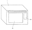
図1は、本発明に係る実施の形態1の蒸気発生装置を備えた加熱調理器の正面断面図を示す。
(Embodiment 1)
FIG. 1 shows a front cross-sectional view of a cooking device provided with the steam generator according to Embodiment 1 of the present invention.

図1において、実施の形態1の加熱調理器は、アルミメッキ鋼板の表面をフッ素塗装して構成され、被加熱物である食品5を収納する加熱室1を有している。加熱室1内には、食品5を載置し加熱室1に出し入れ可能な載置皿4と、載置皿4を保持するレール12と、加熱室1に固定され食品5を載置する結晶化ガラスで形成された載置台3と、加熱室1の天面付近に3本平行に設けられた加熱室ヒータ2とを備えている。加熱室ヒータ2の3本のうち中央部に配置された加熱室ヒータ2の波長のピーク値は他の2本の加熱室ヒータ2の波長のピーク値よりも短く設定されている。   In FIG. 1, the heating cooker of Embodiment 1 has a heating chamber 1 that is configured by coating the surface of an aluminum-plated steel sheet with fluorine and that stores a food 5 that is a heated object. In the heating chamber 1, a food tray 5 on which food 5 can be placed and taken in and out of the heating chamber 1, a rail 12 that holds the food tray 4, and a crystal that is fixed in the heating chamber 1 and on which food 5 is placed. A mounting table 3 made of a vitrified glass and three heating chamber heaters 2 provided in parallel near the top surface of the heating chamber 1 are provided. Of the three heating chamber heaters 2, the wavelength peak value of the heating chamber heater 2 disposed at the center is set shorter than the wavelength peak values of the other two heating chamber heaters 2.

加熱室1を構成する壁面は、アース線(図示せず)に接続されて接地されており、加熱室1と一体成型されたレール12も接地状態である。   The wall surface constituting the heating chamber 1 is connected to a ground wire (not shown) and grounded, and the rail 12 formed integrally with the heating chamber 1 is also in a grounded state.

実施の形態1における加熱室1を構成する壁面は、汚れを拭き取りやすいフッ素塗装を行った例で説明するが、ホーロー塗装や他の耐熱性のある塗装を行ってもよい。また、加熱室1の材質としてはアルミメッキ鋼鈑を用いた例で説明するが、他の金属を用いてもよく、例えばステンレスを用いることもできる。   Although the wall surface which comprises the heating chamber 1 in Embodiment 1 demonstrates in the example which performed the fluorine coating which is easy to wipe off dirt, you may perform enamel coating and other heat resistant coating. Moreover, although the example which used the aluminum plating steel plate is demonstrated as a material of the heating chamber 1, another metal may be used, for example, stainless steel can also be used.

載置皿4は、アルミメッキ鋼鈑で形成されており、載置皿4上の食品5を加熱した時に食品5からの油脂分が流れ出やすいようにプレスで凹凸加工されている。
また、載置皿4の表面はフッ素塗装され、裏面にはマイクロ波を吸収して発熱する発熱体が備えられている。このように、載置皿4の裏面に発熱体を備えることにより、食品5の上方に設けられた加熱室ヒータ2と、載置皿4の裏面の発熱体との組み合わせにより、食品5の両面を加熱することができる。なお、載置皿4とレール12との接触部分には加熱室1と絶縁するためにPPS樹脂の成型品が備えられている。
The mounting plate 4 is formed of an aluminum-plated steel plate, and is unevenly processed with a press so that the oil and fat from the food 5 can easily flow out when the food 5 on the mounting plate 4 is heated.
In addition, the surface of the mounting plate 4 is coated with fluorine, and a heating element that absorbs microwaves and generates heat is provided on the back surface. Thus, by providing a heating element on the back surface of the mounting tray 4, both sides of the food 5 are combined by combining the heating chamber heater 2 provided above the food 5 and the heating body on the back surface of the mounting tray 4. Can be heated. In addition, in order to insulate from the heating chamber 1 in the contact part of the mounting tray 4 and the rail 12, the molded product of PPS resin is provided.

実施の形態1において、載置皿4の表面は汚れを拭き取りやすいフッ素塗装を行った例で説明するが、ホーロー塗装や他の耐熱性のある塗装を行ってもよい。また、載置皿4の材質としてはアルミニウムの例で説明したが、他の金属、例えばステンレスを用いることもできる。   In the first embodiment, the surface of the mounting plate 4 will be described with an example in which fluorine coating is applied to easily remove dirt, but enamel coating or other heat-resistant coating may be performed. Moreover, although the example of aluminum was demonstrated as a material of the mounting tray 4, another metal, for example, stainless steel, can also be used.

加熱室1の奥である背面側には加熱室1内の空気を撹拌、循環させる循環ファン7と、加熱室1内を循環する空気を加熱する室内加熱ヒータであるコンベクションヒータ8が循環ファン7を取り囲むように設けられている。   A circulation fan 7 that stirs and circulates the air in the heating chamber 1 and a convection heater 8 that is an indoor heater that heats the air that circulates in the heating chamber 1 are provided on the back side, which is the back of the heating chamber 1. Is provided so as to surround.

加熱室1の背面中央付近には加熱室1側から循環ファン7側に吸気を行う複数の吸気用通風孔16が形成されている。逆に、循環ファン7側から加熱室1側に送風を行う複数の送風用通風孔17が、加熱室1の背面におけるコンベクションヒータ8の外周領域の特定区域に形成エリアを区別して形成されている。吸気用通風孔16及び送風用通風孔17は多数のパンチング孔で形成されている。   Near the center of the back surface of the heating chamber 1, a plurality of intake vent holes 16 are formed for intake from the heating chamber 1 side to the circulation fan 7 side. Conversely, a plurality of ventilation holes 17 for blowing air from the circulation fan 7 side to the heating chamber 1 side are formed in a specific area in the outer peripheral region of the convection heater 8 on the back surface of the heating chamber 1. . The intake ventilation holes 16 and the ventilation ventilation holes 17 are formed by a number of punching holes.

実施の形態1の加熱調理器には、図1に示すように、加熱室1を構成する右方の壁面(右壁面)に検出用孔46が形成されており、この検出用孔46を通じて加熱室1内の食品5の温度が赤外線センサ15により検出される。また、加熱室1の庫内温度は、加熱室1の上部に設けられた庫内サーミスタ9により検出される。   In the heating cooker according to the first embodiment, as shown in FIG. 1, a detection hole 46 is formed on the right wall surface (right wall surface) constituting the heating chamber 1, and heating is performed through the detection hole 46. The temperature of the food 5 in the chamber 1 is detected by the infrared sensor 15. Further, the internal temperature of the heating chamber 1 is detected by an internal thermistor 9 provided in the upper part of the heating chamber 1.

図1に示す実施の形態1の加熱調理器において、加熱室1の下方における左壁面の下にはマイクロ波発生手段であるマグネトロン6が水平方向に出力端が導出するよう設けられている。実施の形態1において用いられているマグネトロン6は、図1における左方から見て約80mm×80mm角である。マグネトロン6は、加熱室1の底面直下において、アルミメッキ鋼鈑を曲げて略L字状の内部通路を有する導波管14に接続されている。水平方向に導出するマグネトロン6の出力端は、導波管14の内部に導出されており、マグネトロン6からのマイクロ波が導波管14の内部通路を伝送する。   In the heating cooker according to the first embodiment shown in FIG. 1, a magnetron 6 as a microwave generating means is provided below the left wall surface below the heating chamber 1 so that the output end is led out in the horizontal direction. The magnetron 6 used in the first embodiment is about 80 mm × 80 mm square when viewed from the left in FIG. The magnetron 6 is connected to a waveguide 14 having a substantially L-shaped internal passage by bending an aluminized steel plate just below the bottom surface of the heating chamber 1. The output end of the magnetron 6 led out in the horizontal direction is led out into the waveguide 14, and the microwave from the magnetron 6 transmits the internal passage of the waveguide 14.

加熱室1の底面における中央付近にはアルミニウムで構成された回転アンテナ11が設けられており、回転アンテナ11は加熱室1の底面直下の導波管14の内部から開口を通って加熱室1内に突設されている。回転アンテナ11は、モータ18により回動されて、導波管14から加熱室1内に放射されるマイクロ波を攪拌する電波撹拌手段としての機能を有する。   A rotating antenna 11 made of aluminum is provided in the vicinity of the center of the bottom surface of the heating chamber 1, and the rotating antenna 11 passes through an opening from the inside of the waveguide 14 immediately below the bottom surface of the heating chamber 1 and passes through the opening in the heating chamber 1. Projected to The rotating antenna 11 is rotated by a motor 18 and has a function as a radio wave agitating unit that agitates microwaves radiated from the waveguide 14 into the heating chamber 1.

なお、実施の形態1の構成においては、マグネトロン6、回転アンテナ11、モータ18、および導波管14を、加熱室1の下部側に設けているが、本発明はこの構成に限定されない。これらの要素を加熱室1の上部側、または側面側に設けることも可能であり、それぞれの要素の設置方向も各要素に対応してあらゆる方向に設定することが可能である。   In the configuration of the first embodiment, the magnetron 6, the rotating antenna 11, the motor 18, and the waveguide 14 are provided on the lower side of the heating chamber 1, but the present invention is not limited to this configuration. These elements can also be provided on the upper side or the side of the heating chamber 1, and the installation direction of each element can be set in any direction corresponding to each element.

上記のように構成された実施の形態1の加熱調理器は、蒸気発生装置20を備える。図1に示すように、加熱調理器を正面から見たとき、加熱室1の左側には、蒸気を発生させるための水を貯める貯水室19と、貯水室19の開口にパッキン(図示せず)を挟んで対向して設けられた貯水室カバー34とが設けられている。貯水室19と貯水室カバー34はともにアルミダイキャストで形成されている。   The heating cooker according to Embodiment 1 configured as described above includes a steam generator 20. As shown in FIG. 1, when the cooking device is viewed from the front, on the left side of the heating chamber 1, there is a water storage chamber 19 for storing water for generating steam, and a packing (not shown) in the opening of the water storage chamber 19. ) And a water storage chamber cover 34 provided opposite to each other. Both the water storage chamber 19 and the water storage chamber cover 34 are formed by aluminum die casting.

また、実施の形態1における蒸気発生装置20は、貯水室19の高さ方向に対して中央付近に略水平方向に設けられた第1の蒸気発生ヒータ40と、第1の蒸気発生ヒータ40の上方に略水平方向に設けられた第2の蒸気発生ヒータ41とを備える。第1の蒸気発生ヒータ40及び第2の蒸気発生ヒータ41はともに、貯水室19内の水を加熱して蒸気を発生させるものであり、貯水室19のアルミダイキャストに鋳込まれている。第1の蒸気発生ヒータ40は出力650Wの直線状のシーズヒータであり、第2の蒸気発生ヒータ41は出力350Wの直線状のシーズヒータである。   Further, the steam generator 20 according to the first embodiment includes a first steam generating heater 40 provided in a substantially horizontal direction near the center with respect to the height direction of the water storage chamber 19, and the first steam generating heater 40. And a second steam generating heater 41 provided in a substantially horizontal direction above. Both the first steam generation heater 40 and the second steam generation heater 41 heat the water in the water storage chamber 19 to generate steam, and are cast into an aluminum die cast of the water storage chamber 19. The first steam generating heater 40 is a linear sheathed heater with an output of 650 W, and the second steam generating heater 41 is a linear sheathed heater with an output of 350 W.

実施の形態1においては、貯水室19内の水を加熱して蒸気を発生させる加熱部である第1の蒸気発生ヒータ40及び第2の蒸気発生ヒータ41として、出力が異なる直線状のシーズヒータを2本用いて、合計の出力を1000Wとしている(下方が650W、上方が350W)。このような場合に限らず、必要な蒸気量等に応じて、所望の出力を有するヒータを設けるようにしても良い。例えば、出力合計1000W以外となるヒータや、出力が同じ複数本のヒータや、3本以上や1本だけのヒータを用いても良い。また、ヒータの形状としては、直線状のヒータ以外の各種形状のヒータを用いることが可能であり、例えばU字形状やL字形状のヒータ等を用いることができる。また、上方に位置するヒータの出力を、下方に位置するヒータの出力よりも大きくしても良い。   In the first embodiment, linear sheathed heaters having different outputs are used as the first steam generating heater 40 and the second steam generating heater 41 which are heating units that heat the water in the water storage chamber 19 to generate steam. Are used, and the total output is 1000 W (lower is 650 W, upper is 350 W). In addition to such a case, a heater having a desired output may be provided according to the required amount of steam or the like. For example, a heater with a total output other than 1000 W, a plurality of heaters having the same output, or three or more heaters or only one heater may be used. Moreover, as a shape of a heater, it is possible to use heaters of various shapes other than a linear heater, for example, a U-shaped or L-shaped heater can be used. Further, the output of the heater located above may be larger than the output of the heater located below.

また、貯水室19の天面には、上方向に導出するように蒸気導入路23が接合されている。蒸気導入路23は、貯水室19から上方向に導出した後、加熱室1の外面を沿うようにL字形状に曲げられて、加熱室1の側面の上方部分に蒸気噴出口21を介して接続されている。蒸気導入路23は、内径φ10mmのシリコーンチューブで形成されている。蒸気導入路23と接続された蒸気噴出口21から、加熱室1内に蒸気が吹出される。   Further, a steam introduction path 23 is joined to the top surface of the water storage chamber 19 so as to lead out upward. The steam introduction path 23 is led upward from the water storage chamber 19, and then bent into an L shape along the outer surface of the heating chamber 1. It is connected. The steam introduction path 23 is formed of a silicone tube having an inner diameter of φ10 mm. Steam is blown into the heating chamber 1 from the steam outlet 21 connected to the steam introduction path 23.

また、第2の蒸気発生ヒータ41の上方には、貯水室19内の温度を検知する貯水室サーミスタ42が設けられる。   Further, a water storage chamber thermistor 42 that detects the temperature in the water storage chamber 19 is provided above the second steam generating heater 41.

また、実施の形態1の蒸気発生装置20において、貯水室19の天面から上方向に導出する蒸気導入路23及び蒸気噴出口21の断面が円形状である例で説明するが、楕円形状や矩形状でもよい。また、蒸気噴出口21は加熱室1の側面の上方に1つだけ設けた例で説明するが、加熱室1の天面や底面等の加熱室1内に蒸気を供給できればよく、1つだけでなく複数個備えてもよい。   Further, in the steam generator 20 of the first embodiment, an example in which the cross section of the steam introduction path 23 and the steam outlet 21 leading upward from the top surface of the water storage chamber 19 is circular will be described. It may be rectangular. Although only one steam outlet 21 is provided above the side surface of the heating chamber 1, it is only necessary to supply steam into the heating chamber 1 such as the top or bottom of the heating chamber 1. You may provide two or more.

なお、蒸気噴出口21の孔の最長内寸は、加熱室1内のマイクロ波が漏れないように、マイクロ波の波長の1/2以下が好ましい。実施の形態1においては、マイクロ波の波長が約120mmであるため、蒸気噴出口21の孔の最長内寸は60mm以下が望ましい。   In addition, the longest inner dimension of the hole of the steam ejection port 21 is preferably ½ or less of the wavelength of the microwave so that the microwave in the heating chamber 1 does not leak. In the first embodiment, since the wavelength of the microwave is about 120 mm, the longest inner dimension of the hole of the steam outlet 21 is desirably 60 mm or less.

また、スケール付着を減らすために、貯水室19の内面または貯水室カバー34の内面をフッ素やシリコーン等でコーティングしてもよい。   In order to reduce scale adhesion, the inner surface of the water storage chamber 19 or the inner surface of the water storage chamber cover 34 may be coated with fluorine, silicone, or the like.

また、貯水室サーミスタ42のような温度検知手段を用いることにより、水位を検知する水位検知手段を用いる場合と異なり、検知部にスケールが付着してもより長く継続的に検知を行うことができる。これにより、スケールに対する信頼性を高くすることができる。   Further, by using a temperature detecting means such as the water storage chamber thermistor 42, unlike the case of using a water level detecting means for detecting the water level, even if a scale adheres to the detecting portion, it can be continuously detected for a longer time. . Thereby, the reliability with respect to a scale can be made high.

実施の形態1の加熱調理器においては、導波管14の下方に制御手段10が設けられている。制御部10は、ユーザの調理メニューの選択に応じて、マグネトロン6、モータ18、循環ファン7、加熱室ヒータ2、第1の蒸気発生ヒータ40、第2の蒸気発生ヒータ41、コンベクションヒータ8、庫内サーミスタ9、貯水室サーミスタ42、赤外線センサ15、給水ポンプ28、操作表示部39等を制御している。   In the heating cooker according to the first embodiment, the control means 10 is provided below the waveguide 14. The control unit 10 selects the magnetron 6, the motor 18, the circulation fan 7, the heating chamber heater 2, the first steam generating heater 40, the second steam generating heater 41, the convection heater 8, The inside thermistor 9, the water storage thermistor 42, the infrared sensor 15, the water supply pump 28, the operation display unit 39, and the like are controlled.

図2は、本発明に係る実施の形態1の蒸気発生装置20を備えた加熱調理器の外観を示す斜視図である。   FIG. 2 is a perspective view showing the external appearance of the cooking device provided with the steam generator 20 according to Embodiment 1 of the present invention.

実施の形態1の加熱調理器の前面には、扉45が設けられている。扉45は、底面側を支点として手前側に開くことができ、これにより、加熱室1内に対して被加熱物である食品5を出し入れすることができる。また、加熱調理器の前面には、ユーザが調理メニューや調理時間を設定するための操作表示部39が備えられている。また、実施の形態1の加熱調理器には、扉45を開いた時にマグネトロン6や各ヒータの動作を停止することができる安全スイッチ(図示せず)が備えられている。   A door 45 is provided on the front surface of the heating cooker according to the first embodiment. The door 45 can be opened to the near side with the bottom surface side as a fulcrum, whereby the food 5 that is the object to be heated can be taken in and out of the heating chamber 1. Moreover, the operation display part 39 for a user to set a cooking menu and cooking time is provided in the front surface of the heating cooker. Further, the cooking device of the first embodiment is provided with a safety switch (not shown) that can stop the operation of the magnetron 6 and each heater when the door 45 is opened.

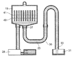
図3は、本発明に係る実施の形態1の加熱調理器における蒸気発生装置20を模式的に示す縦断面図である。   FIG. 3 is a longitudinal sectional view schematically showing the steam generator 20 in the cooking device of the first embodiment according to the present invention.

貯水室19の内壁の中央付近には、複数のフィン22が設けられている。フィン22は、第1の蒸気発生ヒータ40と第2の蒸気発生ヒータ41を略垂直に横切るように、水平方向に約5mm間隔で並べられている。フィン22は貯水室19と一体的であり、実施の形態1ではそれぞれの厚みが約2mmである。また、フィン22の長手方向は、蒸気発生方向と略同一方向に設定されている。すなわち、フィン22は、蒸気発生方向に沿って形成されている。なお、蒸気発生方向とは、水中で発生した蒸気が水面に向かう方向、又は水面から出た蒸気が向かう方向のことであり、本実施の形態1では、貯水室19内の水面に垂直な方向、又は貯水室19内での上下方向のことである。   A plurality of fins 22 are provided near the center of the inner wall of the water storage chamber 19. The fins 22 are arranged at intervals of about 5 mm in the horizontal direction so as to cross the first steam generating heater 40 and the second steam generating heater 41 substantially vertically. The fins 22 are integrated with the water storage chamber 19, and in the first embodiment, each thickness is about 2 mm. Further, the longitudinal direction of the fin 22 is set in substantially the same direction as the steam generation direction. That is, the fin 22 is formed along the steam generation direction. Note that the steam generation direction is a direction in which steam generated in water is directed toward the water surface, or a direction in which steam emitted from the water surface is directed, and in the first embodiment, a direction perpendicular to the water surface in the water storage chamber 19. Or the vertical direction within the water storage chamber 19.

なお、フィン22の厚み、長さ及び間隔は、貯水室19の形状や、第1の蒸気発生ヒータ40と第2の蒸気発生ヒータ41の出力及び形状等に応じて、適宜決定してもよい。   Note that the thickness, length, and interval of the fins 22 may be appropriately determined according to the shape of the water storage chamber 19, the outputs and shapes of the first steam generation heater 40 and the second steam generation heater 41, and the like. .

貯水室19の内面における底面は、その中央部が最下端となるように水平面に対して角度約5°の傾斜を有する傾斜面24である。すなわち、貯水室19の底面は、いわゆる漏斗状に形成されており、その中央部である最下点に排水口37が設けられている。また、貯水室19へ水を給水するための給水口36は、貯水室19の傾斜面24に形成されている。給水口36は排水口37の図3における左方側に設けられており、給水口36と排水口37は貯水室19の底面における別々の位置に設けられている。   The bottom surface of the inner surface of the water storage chamber 19 is an inclined surface 24 having an inclination of an angle of about 5 ° with respect to the horizontal plane so that the central portion thereof is the lowest end. That is, the bottom surface of the water storage chamber 19 is formed in a so-called funnel shape, and a drain port 37 is provided at the lowest point that is the central portion. A water supply port 36 for supplying water to the water storage chamber 19 is formed in the inclined surface 24 of the water storage chamber 19. The water supply port 36 is provided on the left side of the drainage port 37 in FIG. 3, and the water supply port 36 and the drainage port 37 are provided at different positions on the bottom surface of the water storage chamber 19.

実施の形態1における傾斜面24の傾斜角度は、水平面に対して約5°としたが、排水路30の形状や排水時の給水量等により水の流れが異なるため、当該加熱調理器の仕様において必要とする水流等に応じて適宜決定される。   Although the inclination angle of the inclined surface 24 in the first embodiment is about 5 ° with respect to the horizontal plane, the flow of water varies depending on the shape of the drainage channel 30 and the amount of water supplied during drainage. Is appropriately determined according to the water flow and the like required.

図3において、給水口36の下方となる上流側には半透明で弾性体のシリコーンで形成された内径φ6の給水路27の一端が接続されている。この給水路27の他端は、給水装置である給水ポンプ28を介して給水タンク29に接続されている。このように、貯水室19に設けられた給水口36及び給水路27を通じて、貯水室内に水を給水する給水装置として給水ポンプ28が設けられている。   In FIG. 3, one end of a water supply passage 27 having an inner diameter φ6 made of semitransparent and elastic silicone is connected to the upstream side below the water supply port 36. The other end of the water supply passage 27 is connected to a water supply tank 29 via a water supply pump 28 which is a water supply device. As described above, the water supply pump 28 is provided as a water supply device for supplying water into the water storage chamber through the water supply port 36 and the water supply passage 27 provided in the water storage chamber 19.

一方、排水口37の下方となる下流側には第1の排水路25と第2の排水路35が連続する排水路30が備えられている。第1の排水路25は半透明で弾性体のシリコーンで形成され、内径がφ6の管状である。第1の排水路25はチューブ等の別部品を用いることなく排水口37に接続されている。図3に示すように、第1の排水路25は、排水口37から下方(略鉛直方向)に延設されており、排水口37から所定の長さで略水平方向に屈曲し、さらに所定の長さで上方(略垂直方向)に屈曲している。即ち、第1の排水路25は、所謂、下方に凸となるU字状の形状を有している。   On the other hand, a drainage channel 30 in which the first drainage channel 25 and the second drainage channel 35 are continuous is provided on the downstream side below the drainage port 37. The first drainage channel 25 is translucent and formed of elastic silicone, and has a tubular shape with an inner diameter of φ6. The first drainage channel 25 is connected to the drainage port 37 without using a separate part such as a tube. As shown in FIG. 3, the first drainage channel 25 extends downward (substantially in the vertical direction) from the drainage port 37, bends in a substantially horizontal direction at a predetermined length from the drainage port 37, and further And bent upward (substantially in the vertical direction). That is, the first drainage channel 25 has a so-called U-shape that protrudes downward.

なお、実施の形態1における第1の排水路25としては、シリコーンを用いた例で説明したが、フッ素、ポリプロピレン、ポリエチレン等を用いることもできる。また、第1の排水路25として金属パイプを用いるとともに、少なくともその内面をフッ素、シリコーン等でコーティングしてもよい。   In addition, although the example which used silicone was demonstrated as the 1st drainage channel 25 in Embodiment 1, fluorine, a polypropylene, polyethylene, etc. can also be used. Further, a metal pipe may be used as the first drainage channel 25 and at least the inner surface thereof may be coated with fluorine, silicone, or the like.

第1の排水路25の下流側には、内径φ6の銅パイプを曲げて形成された第2の排水路35がチューブ等の別部品を用いることなく接続されている。第2の排水路35は、第1の排水路25との接合部分から第1の蒸気発生ヒータ40及び第2の蒸気発生ヒータ41の水平位置を超えて上方に延設されている。第2の排水路35は、貯水室19の内面における天面の頂点と略同一高さである排水路頂点32を頂点として180°屈曲しており、排水路頂点32より下流側は鉛直方向の下方に延設されている。即ち、第2の排水路35は、所謂、上方に凸となる逆U字状の形状を有している。このように形成された第2の排水路35は、第1の排水路25から流れてきた水を、排水路出口33を通して排水タンク31に流す。第2の排水路35の排水路出口33は、貯水室19の底面より下方の位置に設けられている。   A second drainage channel 35 formed by bending a copper pipe having an inner diameter φ6 is connected to the downstream side of the first drainage channel 25 without using another part such as a tube. The second drainage channel 35 extends upward beyond the horizontal position of the first steam generation heater 40 and the second steam generation heater 41 from the joint portion with the first drainage channel 25. The second drainage channel 35 is bent 180 ° with the drainage channel apex 32 having the same height as the apex of the top surface on the inner surface of the water storage chamber 19 as the apex, and the downstream side of the drainage channel apex 32 is in the vertical direction. It extends downward. That is, the second drainage channel 35 has a so-called inverted U-shape that is convex upward. The second drainage channel 35 thus formed allows the water flowing from the first drainage channel 25 to flow to the drainage tank 31 through the drainage channel outlet 33. The drainage channel outlet 33 of the second drainage channel 35 is provided at a position below the bottom surface of the water storage chamber 19.

実施の形態1においては、第2の排水路35を銅パイプを用いた例で説明したが、アルミ、鉄等の材質のパイプを用いることもできる。   In Embodiment 1, although the example which used the copper pipe for the 2nd drainage channel 35 was demonstrated, the pipe of materials, such as aluminum and iron, can also be used.

給水タンク29は、容器部と蓋部の2つの部品で構成されており、それぞれが透明な非晶性のプラスチックであるAS樹脂で形成されている。給水タンク29の容器部と蓋部は、パッキン(図示せず)を挟んで水が漏れないように密閉されている。給水タンク29の側面には排水ライン26と満水ライン38がシルク印刷により表示されている。給水タンク29の排水ライン26まで注水すると約100mlとなり、貯水室19内の内容積より10ml程多い容量となる。給水タンク29の満水ライン38まで注水すると約400mlとなる。なお、図3に示す貯水室19、給水タンク29および排水タンク31は、実際の相対的な容量を示しておらず、貯水室19は、給水タンク29および排水タンク31に比べて容量を誇張して示している。   The water supply tank 29 is composed of two parts, a container part and a lid part, each made of AS resin, which is a transparent amorphous plastic. The container portion and the lid portion of the water supply tank 29 are sealed so that water does not leak through a packing (not shown). On the side surface of the water supply tank 29, a drain line 26 and a full water line 38 are displayed by silk printing. When the water is poured into the drainage line 26 of the water supply tank 29, the volume becomes about 100 ml, which is about 10 ml larger than the internal volume in the water storage chamber 19. When the water is filled up to the full water line 38 of the water supply tank 29, it becomes about 400 ml. Note that the water storage chamber 19, the water supply tank 29, and the drainage tank 31 shown in FIG. 3 do not show actual relative capacities, and the water storage chamber 19 has an exaggerated capacity compared to the water supply tank 29 and the drainage tank 31. It shows.

実施の形態1においては、排水ライン26と満水ライン38をシルク印刷により表示した例で説明したが、このようなシルク印刷に限るものではなく、給水タンク29に刻印を付けたり、給水タンク29に凹凸部を設けて表示してもよい。   In the first embodiment, the drainage line 26 and the full water line 38 have been described using silk printing. However, the present invention is not limited to such silk printing, and the water supply tank 29 is engraved or the water supply tank 29 is marked. An uneven portion may be provided and displayed.

図4は、本発明に係る実施の形態1の蒸気発生装置20を模式的に示す横断面図である。   FIG. 4 is a cross-sectional view schematically showing the steam generator 20 according to Embodiment 1 of the present invention.

フィン22は、貯水室19の第1の側面19Aから延出されるとともに、第1の側面19Aと対向する貯水室カバー34で形成された第2の側面19Bに対してフィン22の先端が離間している。本実施の形態1では、貯水室19から延出されたフィン22の先端と貯水室カバー34との間隔は約2mmである。また、蒸気発生方向に垂直な断面における貯水室19、フィン22及び貯水室カバー34で形成される空間の断面積(図4で貯水室19、フィン22及び貯水室カバー34で囲まれた白抜き部分の全体)は、蒸気噴出口21の断面積以上に設定されている。   The fin 22 extends from the first side surface 19A of the water storage chamber 19, and the tip of the fin 22 is separated from the second side surface 19B formed by the water storage chamber cover 34 facing the first side surface 19A. ing. In the first embodiment, the distance between the tip of the fin 22 extending from the water storage chamber 19 and the water storage chamber cover 34 is about 2 mm. Further, the sectional area of the space formed by the water storage chamber 19, the fins 22 and the water storage chamber cover 34 in the cross section perpendicular to the steam generation direction (the white space surrounded by the water storage chamber 19, the fins 22 and the water storage chamber cover 34 in FIG. 4). The whole part) is set to be equal to or larger than the cross-sectional area of the steam outlet 21.

なお、本実施の形態1では、貯水室19から延出されたフィン22の先端と貯水室カバー34との間隔は約2mmであるが、フィン22と貯水室カバー34との間に隙間が存在して水が侵入できるのであれば、この間隔を大きく又は小さくしても良い。   In the first embodiment, the distance between the tip of the fin 22 extended from the water storage chamber 19 and the water storage chamber cover 34 is about 2 mm, but there is a gap between the fin 22 and the water storage chamber cover 34. If water can enter, this interval may be increased or decreased.

次に、上記のように構成された実施の形態1の蒸気発生装置20を備えた加熱調理器について、その動作および作用について説明する。   Next, the operation and action of the cooking device provided with the steam generator 20 of the first embodiment configured as described above will be described.

まず、使用者により、マイクロ波加熱モードが選択されて、起動スイッチがON状態にされた場合には、マグネトロン6からマイクロ波が放出される。マグネトロン6から放出されたマイクロ波は、導波管14内を伝搬し、回転アンテナ11を照射する。モータ18によって回転する回転アンテナ11により、マイクロ波が加熱室1内に撹拌されながら供給される。加熱室1内に供給されたマイクロ波は、被加熱物である食品5に直接吸収されるものもあれば、加熱室1の壁面を反射しながら食品5に吸収されて、食品5を加熱するものもある。また、自動加熱時においては、主に赤外線センサ15や庫内サーミスタ9を用いて食品や庫内の状態を検知し、検知された状態に応じて、出力やマイクロ波の放出方向を制御する。なお、このマイクロ波加熱モードの動作時においては、加熱室1の内部から載置皿4が取り外されており、載置台3の上に食品5が載置されて加熱される。   First, when the microwave heating mode is selected by the user and the start switch is turned on, the microwave is emitted from the magnetron 6. The microwave emitted from the magnetron 6 propagates in the waveguide 14 and irradiates the rotating antenna 11. The microwave is supplied into the heating chamber 1 while being stirred by the rotating antenna 11 rotated by the motor 18. The microwave supplied into the heating chamber 1 is directly absorbed by the food 5 that is the object to be heated, and is absorbed by the food 5 while reflecting the wall surface of the heating chamber 1 to heat the food 5. There are also things. Moreover, at the time of automatic heating, the food or the state in the warehouse is mainly detected using the infrared sensor 15 and the thermistor 9 in the warehouse, and the output and the microwave emission direction are controlled according to the detected state. During the operation in the microwave heating mode, the placing plate 4 is removed from the inside of the heating chamber 1, and the food 5 is placed on the placing table 3 and heated.

一方、使用者により、オーブン加熱モードが選択されて、起動スイッチがON状態にされた場合には、加熱室ヒータ2またはコンベクションヒータ8が通電されて発熱し、循環ファン7によって加熱室1内を熱風が循環して、食品5が加熱される。また、自動加熱時においては、主に赤外線センサ15や庫内サーミスタ9を用いて食品や庫内の状態を検知し、検知された状態に応じて、加熱室ヒータ2とコンベクションヒータ8の切り替えや、出力の制御を行う。   On the other hand, when the oven heating mode is selected by the user and the start switch is turned on, the heating chamber heater 2 or the convection heater 8 is energized to generate heat, and the circulation fan 7 allows the inside of the heating chamber 1 to be heated. Hot air circulates and the food 5 is heated. Further, during automatic heating, the state of food or the inside of the cabinet is detected mainly using the infrared sensor 15 or the thermistor 9 in the cabinet, and the heating chamber heater 2 and the convection heater 8 are switched according to the detected status. Control the output.

使用者が加熱室1内に載置皿4をセットし、グリル加熱モードを選択して、起動スイッチをON状態とすると、マイクロ波加熱モードと同様にマイクロ波が加熱室1内に供給され、載置皿4の裏面の発熱体が発熱する。発熱した発熱体の熱が熱伝導により載置皿4の全体が高温度となり、食品5を下方から加熱する。   When the user sets the mounting plate 4 in the heating chamber 1, selects the grill heating mode, and turns on the start switch, the microwave is supplied into the heating chamber 1 as in the microwave heating mode. The heating element on the back surface of the mounting tray 4 generates heat. The heat of the heat generating element that has generated heat causes the entire mounting tray 4 to become a high temperature due to heat conduction, and the food 5 is heated from below.

このとき同時に、マイクロ波が載置皿4と加熱室1の壁面との隙間から回り込み、食品5が加熱させられる。また、グリル加熱モードにおいては、加熱室ヒータ2に通電されて発熱し、その輻射熱により食品5を上方から加熱する。このグリル加熱モードにおいては、使用者による設定内容に応じて、マイクロ波による加熱とともに加熱室ヒータ2による輻射加熱を同時に行う場合と、マイクロ波による加熱または加熱室ヒータ2による輻射加熱のそれぞれを単独で行う場合が自動的に選択される。   At the same time, the microwaves wrap around the gap between the mounting plate 4 and the wall surface of the heating chamber 1 to heat the food 5. In the grill heating mode, the heating chamber heater 2 is energized to generate heat, and the food 5 is heated from above by its radiant heat. In this grill heating mode, the heating by the heating chamber heater 2 and the radiant heating by the heating chamber heater 2 are performed simultaneously with the heating by the microwave and the heating by the microwave or the radiant heating by the heating chamber heater 2 according to the setting contents by the user. The case of performing in is automatically selected.

また、自動加熱時においては、主に赤外線センサ15や庫内サーミスタ9を用いて食品や庫内の状態を検知し、検知した状態に応じて、マイクロ波と加熱室ヒータ2との切り替えや、出力の制御を行う。   Moreover, at the time of automatic heating, mainly the infrared sensor 15 or the internal thermistor 9 is used to detect the state of the food or the internal storage, and according to the detected state, switching between the microwave and the heating chamber heater 2, Control the output.

図5は、本発明に係る実施の形態1の蒸気発生装置20におけるスチーム加熱モードのフローチャートを示す。図6は、本発明に係る実施の形態1の蒸気発生装置20が備える貯水室サーミスタの温度と時間の関係を示すグラフである。   FIG. 5 shows a flowchart of the steam heating mode in the steam generator 20 according to Embodiment 1 of the present invention. FIG. 6 is a graph showing the relationship between the temperature of the water storage chamber thermistor provided in the steam generator 20 of Embodiment 1 according to the present invention and time.

まず、ユーザによって、給水タンク29の満水ライン38まで水が補充された後、スチーム加熱モードが選択・決定される(ステップS10)。そうすると、制御手段10は、第1の蒸気発生ヒータ40と第2の蒸気発生ヒータ41を起動(ON)して発熱させる(ステップS11)。   First, the water is replenished to the full water line 38 of the water supply tank 29 by the user, and then the steam heating mode is selected and determined (step S10). Then, the control means 10 starts (ON) the first steam generating heater 40 and the second steam generating heater 41 to generate heat (step S11).

次に、図6のA1に示すように、貯水室サーミスタ42が検知する貯水室19の温度が、通電開始から30秒間で60℃以上上昇した場合(ステップS12)、制御手段10は、給水ポンプ28に給水命令を出し、約40mlの給水を行う(ステップS13)。給水ポンプ28による給水により、給水タンク29の水が、給水ポンプ28から給水路27及び給水口36を通じて貯水室19に給水される。所定量の給水が完了すると、給水ポンプ28の動作が停止される。一方で、図6のA2に示すように、貯水室19の温度上昇値が30秒間で60℃以下かつ50℃を超える場合(ステップS14)、制御手段10は、給水ポンプ28に給水命令を出し、約20mlの給水を行う(ステップS15)。   Next, as shown in A1 of FIG. 6, when the temperature of the water storage chamber 19 detected by the water storage chamber thermistor 42 rises by 60 ° C. or more in 30 seconds from the start of energization (step S12), the control means 10 A water supply command is issued to 28, and about 40 ml of water is supplied (step S13). With the water supply by the water supply pump 28, the water in the water supply tank 29 is supplied from the water supply pump 28 to the water storage chamber 19 through the water supply channel 27 and the water supply port 36. When the predetermined amount of water supply is completed, the operation of the water supply pump 28 is stopped. On the other hand, as shown in A2 of FIG. 6, when the temperature rise value of the water storage chamber 19 is 60 ° C. or less and exceeds 50 ° C. in 30 seconds (step S14), the control means 10 issues a water supply command to the water supply pump 28. About 20 ml of water is supplied (step S15).

図6のA3に示すように、貯水室19の温度上昇値が50℃以下の場合には、貯水室19に十分な水が溜まっていると判断され、給水を行わない(ステップS16)。   As shown in A3 of FIG. 6, when the temperature increase value of the water storage chamber 19 is 50 ° C. or less, it is determined that sufficient water has accumulated in the water storage chamber 19, and water supply is not performed (step S16).

S13やS15において給水ポンプ28による給水が行われたときに、給水後の5秒間で貯水室19の温度上昇値が7℃を超えることがある(ステップS17)。この場合には、制御手段10は、給水ポンプ28に給水命令を出し、約10mlの給水を行う(ステップS18)。前述した5秒間での貯水室19の温度上昇値が7℃を下回るまで、S18による給水が繰り返される。   When water is supplied by the water supply pump 28 in S13 or S15, the temperature rise value of the water storage chamber 19 may exceed 7 ° C. in 5 seconds after the water supply (step S17). In this case, the control means 10 issues a water supply command to the water supply pump 28 and supplies about 10 ml of water (step S18). Water supply by S18 is repeated until the temperature rise value of the water storage chamber 19 in 5 seconds mentioned above falls below 7 degreeC.

こうして貯水室19に給水されると、第2の蒸気発生ヒータ41の下方まで水位が上昇するとともに、水がフィン22に接触するように満たされる。この状態で第1の蒸気発生ヒータ40と第2の蒸気発生ヒータ41による加熱を行うことで、直接的に又はフィン22を介して貯水室19内の水が加熱され、加熱された水が蒸発することで蒸気が発生する。貯水室19で発生した蒸気は、蒸気導入路23を通って蒸気噴出口21から加熱室1内に放出される。加熱室1内に放出された蒸気によって食品5が加熱される。   When water is supplied to the water storage chamber 19 in this manner, the water level rises to the lower side of the second steam generating heater 41 and the water is filled so as to contact the fins 22. In this state, by heating with the first steam generation heater 40 and the second steam generation heater 41, the water in the water storage chamber 19 is heated directly or via the fins 22, and the heated water evaporates. This generates steam. The steam generated in the water storage chamber 19 is discharged into the heating chamber 1 from the steam outlet 21 through the steam introduction path 23. The food 5 is heated by the steam released into the heating chamber 1.

なお、貯水室19と排水路30は連通しているため、貯水室19内の水位が上昇すると、排水路30の水位も同時に上昇する。なお、給水ポンプ28による給水量は、貯水室19内の水位が第2の蒸気発生ヒータ41を超えないように調整されている。   In addition, since the water storage chamber 19 and the drainage channel 30 are connected, if the water level in the water storage chamber 19 rises, the water level of the drainage channel 30 will also rise simultaneously. The amount of water supplied by the water supply pump 28 is adjusted so that the water level in the water storage chamber 19 does not exceed the second steam generation heater 41.

また、自動加熱時においては、主に赤外線センサ15や庫内サーミスタ9を用いて食品や庫内の状態を検知し、検知した状態に応じて、第1の蒸気発生ヒータ40と第2の蒸気発生ヒータ41との切り替えや、出力の制御、及び給水ポンプ28の制御を行う。   Moreover, at the time of automatic heating, mainly the infrared sensor 15 and the internal thermistor 9 are used to detect the state of the food and the internal storage, and the first steam generating heater 40 and the second steam are detected according to the detected state. Switching to the generating heater 41, control of the output, and control of the water supply pump 28 are performed.

上述した制御によれば、貯水室19に少量の水を供給して瞬時に蒸発させるのではなく、貯水室19に水を貯えた状態で蒸発させている。これにより、蒸発が進んでも貯水室19内の水が残りやすくなるため、スケールの析出を抑えることができる。すなわち、信頼性が高い蒸気発生装置20を提供することができる。   According to the control described above, a small amount of water is not supplied to the water storage chamber 19 and instantly evaporated, but is evaporated while water is stored in the water storage chamber 19. Thereby, even if evaporation progresses, water in the water storage chamber 19 is likely to remain, so that scale deposition can be suppressed. That is, the steam generator 20 with high reliability can be provided.

さらに本実施の形態1では、水面(通常水位)の近傍に第1の蒸気発生ヒータ40と第2の蒸気発生ヒータ41を配置している。これにより、貯水室19内における下方の水を温める前に水面付近の水だけを蒸発させることができ、速く蒸気を発生させることができる。すなわち、初期段階における蒸気発生が速い蒸気発生装置20を提供することができる。また、第1の蒸気発生ヒータ40と第2の蒸気発生ヒータ41を複数のフィン22を横切るように配置することで、フィン22を介して水を加熱することができ、均一な加熱を行うことができる。   Further, in the first embodiment, the first steam generating heater 40 and the second steam generating heater 41 are arranged in the vicinity of the water surface (normal water level). Thereby, before warming the water below in the water storage chamber 19, only the water near the water surface can be evaporated, and steam can be generated quickly. That is, it is possible to provide the steam generator 20 that generates steam at an early stage. Further, by arranging the first steam generating heater 40 and the second steam generating heater 41 so as to cross the plurality of fins 22, water can be heated through the fins 22, and uniform heating is performed. Can do.

また本実施の形態1では、水面の下方に第1の蒸気発生ヒータ40を配置するとともに、水面の上方に第2の蒸気発生ヒータ41を配置している。このような配置によれば、下側にある第1の蒸気発生ヒータ40で主に水を加熱して蒸気を発生させつつ、上側にある第2の蒸気発生ヒータ41で主に蒸気や沸騰水を加熱する。第2の蒸気発生ヒータ41により沸騰水を加熱することで沸騰水を蒸気に変えることができるため、沸騰水の駆け上がりを防止することができる。また本実施の形態1では、主に水を加熱する第1の蒸気発生ヒータ40の出力を、主に蒸気や沸騰水を加熱する第2の蒸気発生ヒータ41の出力よりも大きく設定している。このように、求められる加熱量に応じてヒータの出力を設定することで、効率的に蒸気を発生させることができる。   In the first embodiment, the first steam generating heater 40 is disposed below the water surface, and the second steam generating heater 41 is disposed above the water surface. According to such an arrangement, the first steam generation heater 40 on the lower side mainly heats water to generate steam, while the second steam generation heater 41 on the upper side mainly generates steam and boiling water. Heat. Since boiling water can be changed into steam by heating the boiling water by the second steam generating heater 41, the running-up of boiling water can be prevented. Moreover, in this Embodiment 1, the output of the 1st steam generation heater 40 which mainly heats water is set larger than the output of the 2nd steam generation heater 41 which mainly heats steam and boiling water. . Thus, steam can be efficiently generated by setting the output of the heater according to the required heating amount.

なお、本実施の形態1では、満水ライン38まで水を補充した例で説明したが、満水ライン38まで水を補充しなくても、スチーム加熱を行うことができる。   In the first embodiment, an example in which water is replenished up to the full water line 38 has been described.

また、本実施の形態1では、第1の蒸気発生ヒータ40と第2の蒸気発生ヒータ41を同時に通電した例で説明したが、選択された調理メニューや出力によっては、どちらか一方のヒータを単独で通電する場合もある。   In the first embodiment, the first steam generating heater 40 and the second steam generating heater 41 are energized at the same time. However, depending on the selected cooking menu and output, either heater is used. There is also a case where electricity is supplied alone.

第1の蒸気発生ヒータ40と第2の蒸気発生ヒータ41の加熱による蒸発を続けると、貯水室19及び排水路30での水位が下がるとともに、貯水室19の温度が上昇する。   If the evaporation by heating of the first steam generation heater 40 and the second steam generation heater 41 is continued, the water level in the water storage chamber 19 and the drainage channel 30 is lowered and the temperature of the water storage chamber 19 is increased.

その後、予め設定されたスチーム加熱時間が終了したこと、又はスチーム加熱が取り消されたことが判定される(S19)。その判定結果がいずれもNOである場合に、貯水室サーミスタ42が検知する温度が110℃以上になると(S20)、制御手段10は給水ポンプ28に給水命令を出し、約20mlの給水を自動で行う(S21)。   Thereafter, it is determined that the preset steam heating time has ended or that the steam heating has been canceled (S19). If the determination result is NO and the temperature detected by the reservoir thermistor 42 is 110 ° C. or higher (S20), the control means 10 issues a water supply command to the water supply pump 28 and automatically supplies about 20 ml of water. Perform (S21).

S21で給水ポンプ28による給水を行うと、貯水室19の温度が下がる。一度給水を行った後も水の蒸発を続けるが、水位が下がり温度が上昇するまで次の給水は行わない。このような制御により、貯水室19内の水位を一定の水位以上に維持することができる。すなわち、水位センサを用いなくとも、簡易的に水位を検出して給水を行うことができる。   When water is supplied by the water supply pump 28 in S21, the temperature of the water storage chamber 19 is lowered. Even after water is supplied once, water continues to evaporate, but the next water supply is not performed until the water level drops and the temperature rises. By such control, the water level in the water storage chamber 19 can be maintained above a certain level. That is, it is possible to supply water by simply detecting the water level without using a water level sensor.

一方で、給水ポンプ28に給水命令を出しても、貯水室19の温度上昇が止まらない場合には、給水タンク29内の水がなくなった、又は給水ポンプ28等が故障したと判定する。そのように判定された場合には、スチーム加熱を終了するとともに、ブザー音を鳴らし、給水タンク29への注水を促す内容を操作表示部39に表示して、ユーザに報知する。   On the other hand, if the temperature rise of the water storage chamber 19 does not stop even if a water supply command is issued to the water supply pump 28, it is determined that the water in the water supply tank 29 has run out or the water supply pump 28 has failed. When it is determined as such, the steam heating is finished and a buzzer is sounded, and a content for prompting water injection into the water supply tank 29 is displayed on the operation display unit 39 to notify the user.

最終的に、S19において、スチーム加熱時間が終了したこと、又はスチーム加熱が取り消されたことの判定結果がYESである場合には、第1の蒸気発生ヒータ40と第2の蒸気発生ヒータ41への通電を停止して(S22)、調理を終了する(S23)。   Finally, in S19, when the determination result that the steam heating time has ended or the steam heating has been canceled is YES, the process proceeds to the first steam generating heater 40 and the second steam generating heater 41. Is stopped (S22) and cooking is terminated (S23).

なお、図5に示すフローで使用される貯水室19の温度上昇の閾値や、給水を行うタイミングは、第1の蒸気発生ヒータ40と第2の蒸気発生ヒータ41の出力や、貯水室19の形状によって大きく異なるため、給水量も考慮して適宜決定しても良い。   In addition, the threshold value of the temperature rise of the water storage chamber 19 used in the flow shown in FIG. 5 and the timing of water supply are the outputs of the first steam generation heater 40 and the second steam generation heater 41, the water storage chamber 19 Since it varies greatly depending on the shape, it may be appropriately determined in consideration of the amount of water supply.

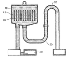
図7Aは、本発明に係る実施の形態1におけるサイフォンの原理による排水工程時の蒸気発生装置20における第1の動作を示す断面図である。図7Bは、本発明に係る実施の形態1におけるサイフォンの原理による排水工程時の蒸気発生装置20における第2の動作を示す断面図である。図7Cは、本発明に係る実施の形態1におけるサイフォンの原理による排水工程時の蒸気発生装置20における第3の動作を示す断面図である。図7Dは、本発明に係る実施の形態1におけるサイフォンの原理による排水工程時の蒸気発生装置20における第4の動作を示す断面図である。   FIG. 7A is a cross-sectional view showing a first operation in steam generating apparatus 20 during the drainage process based on the principle of siphon according to Embodiment 1 of the present invention. FIG. 7B is a cross-sectional view showing a second operation in steam generating apparatus 20 during the drainage process according to the siphon principle according to Embodiment 1 of the present invention. FIG. 7C is a cross-sectional view showing a third operation in steam generating apparatus 20 during the drainage process based on the siphon principle according to Embodiment 1 of the present invention. FIG. 7D is a cross-sectional view showing a fourth operation in steam generating apparatus 20 during the drainage process according to the siphon principle according to Embodiment 1 of the present invention.

図7Aに示すように、通常加熱時は貯水室19内の第2の蒸気発生ヒータ41の上方となる水位まで給水ポンプ28からの給水によって水が貯められ、同時に排水路30内の水位も上昇する。貯水室19内において蒸気が発生していないとき、貯水室19内の水位と排水路30の水位は同じである。一方、貯水室19内において蒸気が発生しているとき、貯水室19内部の圧力が高まり排水路30の水位が上昇するため、貯水室19内の水位と排水路30の水位は必ずしも同一ではない。   As shown in FIG. 7A, during normal heating, water is stored by the water supply from the water supply pump 28 up to the water level above the second steam generating heater 41 in the water storage chamber 19, and at the same time the water level in the drainage channel 30 also rises. To do. When no steam is generated in the water storage chamber 19, the water level in the water storage chamber 19 and the water level in the drainage channel 30 are the same. On the other hand, when steam is generated in the water storage chamber 19, the pressure in the water storage chamber 19 increases and the water level in the drainage channel 30 rises, so the water level in the water storage chamber 19 and the water level in the drainage channel 30 are not necessarily the same. .

図7Bに示すように、スチーム加熱が終了すると、貯水室19内の水位が通常加熱時の水位よりも上方である排水路頂点32に達するまで、自動的に給水ポンプ28を動作させて給水を行う。排水路頂点32まで水位が上昇すると、貯水室19内での水位と排水路30内との水位に高低差aができる。図7Bに示すように、貯水室19内の水位と排水路30内の水位に高低差aができると、図7Cに示すように、サイフォンの原理により貯水室19内および第1の排水路25内のスケール凝縮水および析出したスケールが、排水口37、排水路30、および排水路出口33を通って排水タンク31に向かって流れる。   As shown in FIG. 7B, when the steam heating is completed, the water supply pump 28 is automatically operated to supply water until the water level in the water storage chamber 19 reaches the drainage channel apex 32 that is above the water level during normal heating. Do. When the water level rises to the drainage channel apex 32, there is a height difference a between the water level in the water storage chamber 19 and the water level in the drainage channel 30. As shown in FIG. 7B, when there is a height difference a between the water level in the water storage chamber 19 and the water level in the drainage channel 30, as shown in FIG. 7C, the inside of the water storage chamber 19 and the first drainage channel 25 by the siphon principle. The inner scale condensed water and the deposited scale flow toward the drainage tank 31 through the drainage port 37, the drainage channel 30, and the drainage channel outlet 33.

なお、貯水室19内の水位と排水路30内の水位に高低差aが発生すると排水が始まり、排水流量より給水流量が少ない場合には、給水しても貯水室19内の水位は上昇せず、給水ポンプ28によって排水に必要な給水量より若干多く給水しても、貯水室19を溢れたりすることはない。このため、実施の形態1の蒸気発生装置20においては、給水ポンプ28の動作バラツキを考慮して、排水に必要な給水量より少し多めの給水量となるように駆動時間を設定している。このため、実施の形態1の蒸気発生装置20の構成においては、排水時の貯水室19内の水位を検知する検知手段は省略することができる。   In addition, when a difference in height a occurs between the water level in the water storage chamber 19 and the water level in the drainage channel 30, drainage begins. If the feed water flow rate is lower than the drainage flow rate, the water level in the water storage chamber 19 rises even if water is supplied. However, even if the water supply pump 28 supplies water slightly more than the amount of water required for drainage, the water storage chamber 19 will not overflow. For this reason, in the steam generator 20 of Embodiment 1, the driving time is set so that the water supply amount is slightly larger than the water supply amount necessary for drainage in consideration of the operation variation of the water supply pump 28. For this reason, in the structure of the steam generator 20 of Embodiment 1, the detection means which detects the water level in the water storage chamber 19 at the time of drainage can be abbreviate | omitted.

最終的に、図7Dに示すように貯水室19内および排水路30の水は空になり、排水タンク31に排水された水が蓄えられる。排水タンク31はユーザによって当該加熱調理器から取り出され、排水タンク31に蓄えられた水が捨てられる。なお、この排水工程では、給水ポンプ28に接続された上流側および下流側である給水ポンプ28の前後の給水路27の水は排水されない。   Finally, as shown in FIG. 7D, the water in the water storage chamber 19 and the drainage channel 30 becomes empty, and the drained water is stored in the drainage tank 31. The drainage tank 31 is taken out from the heating cooker by the user, and the water stored in the drainage tank 31 is discarded. In this drainage process, water in the water supply path 27 before and after the water supply pump 28 on the upstream side and the downstream side connected to the water supply pump 28 is not drained.

このような排水路30の構成を採用するとともに、排水路頂点32まで給水することにより、貯水室19内に析出するスケールをクリーニングしている。これにより、給水を行うだけで、サイフォンの原理による排水を行うことができる。よって、単純な構成を用いながら、スケールおよびスケール凝縮水の排出を行うことができる。すなわち、信頼性が高く、安価で、かつユーザの負担を軽減した蒸気発生装置20を提供することができる。   While adopting such a configuration of the drainage channel 30 and supplying water to the drainage channel apex 32, the scale deposited in the water storage chamber 19 is cleaned. Thereby, drainage by the principle of siphon can be performed only by supplying water. Thus, the scale and the scale condensed water can be discharged while using a simple configuration. That is, it is possible to provide the steam generator 20 that is highly reliable, inexpensive, and reduces the burden on the user.

なお、実施の形態1における蒸気発生装置20においては、スチーム加熱の都度自動排水を行う例で説明したが、使用者が当該蒸気発生装置20を洗浄したいと考えたとき、サイフォンの原理により排水できる手動排水モードを設けてもよい。   In addition, in the steam generator 20 in Embodiment 1, although demonstrated in the example which performs automatic drainage at every steam heating, when a user wants to wash | clean the said steam generator 20, it can drain according to the principle of siphon. A manual drainage mode may be provided.

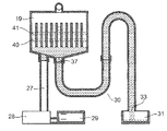
図8Aは、本発明に係る実施の形態1における給水路の水の排水工程時の蒸気発生装置20における第1の動作を示す断面図である。図8Bは、本発明に係る実施の形態1における給水路の水の排水工程時の蒸気発生装置20における第2の動作を示す断面図である。図8Cは、本発明に係る実施の形態1における給水路の水の排水工程時の蒸気発生装置20における第3の動作を示す断面図である。図8Dは、本発明に係る実施の形態1における給水路の水の排水工程時の蒸気発生装置20における第4の動作を示す断面図である。   FIG. 8A is a cross-sectional view showing a first operation in steam generator 20 during the water drainage process of the water supply channel in the first embodiment according to the present invention. FIG. 8B is a cross-sectional view showing a second operation in steam generating apparatus 20 during the water drainage process of the water supply channel in the first embodiment according to the present invention. FIG. 8C is a cross-sectional view showing a third operation in steam generating apparatus 20 during the water drainage process of the water supply channel in the first embodiment according to the present invention. FIG. 8D is a cross-sectional view showing a fourth operation in steam generating apparatus 20 during the water drainage process of the water supply channel in the first embodiment according to the present invention.

使用者により給水タンク29の排水ライン26まで水が補充された後、排水モードが選択されて、起動スイッチがON状態とされると、図8Aに示すように、給水タンク29の水が給水ポンプ28により給水路27および給水口36を通じて貯水室19に給水される。   After the user replenishes water to the drain line 26 of the water supply tank 29, when the drainage mode is selected and the start switch is turned on, the water in the water supply tank 29 is supplied to the water supply pump as shown in FIG. 8A. Water is supplied to the water storage chamber 19 by the water supply passage 27 and the water supply port 36.

さらに給水を続けると、図8Bに示すように、貯水室19および排水路30の水位は、排水路頂点32に達する。給水タンク29には貯水室19内の内容積より10ml程多い容量しか蓄えられていないため、給水タンク29内の水はほとんどなくなる。   When the water supply is further continued, the water levels of the water storage chamber 19 and the drainage channel 30 reach the drainage channel apex 32 as shown in FIG. 8B. Since the water supply tank 29 stores only a capacity about 10 ml larger than the internal volume in the water storage chamber 19, the water in the water supply tank 29 almost disappears.

そして、図8Cに示すように、排水口37、排水路30、および排水路出口33を通って排水タンク31に対してサイフォンの原理による排水が行われる。このように排水タンク31に対して排水が行われている間においてもさらに給水ポンプ28は動作を続ける。給水ポンプ28が動作を続けることにより、給水タンク29内の水は空になり、給水ポンプ28が水ではなく空気を給水路27に送り込むようになる。この結果、給水ポンプ28は給水路27内の水を貯水室19内に空気で押し出して、排水路30から排水する。給水ポンプ28は所定時間経過後に動作を停止する。   Then, as shown in FIG. 8C, drainage by the siphon principle is performed on the drainage tank 31 through the drainage port 37, the drainage channel 30, and the drainage channel outlet 33. Thus, the water supply pump 28 continues to operate even while the drainage tank 31 is drained. As the water supply pump 28 continues to operate, the water in the water supply tank 29 becomes empty, and the water supply pump 28 feeds air, not water, into the water supply path 27. As a result, the water supply pump 28 pushes the water in the water supply channel 27 into the water storage chamber 19 with air and drains it from the drainage channel 30. The feed pump 28 stops operating after a predetermined time has elapsed.

最終的には、図8Dに示すように、貯水室19内に押し出された水がサイフォンの原理による排水と合流して、同時に排水タンク31に向かって排水される。これにより、給水タンク29、給水路27、貯水室19、および排水路30の水は完全に空になる。   Finally, as shown in FIG. 8D, the water pushed into the water storage chamber 19 merges with the drainage by the siphon principle, and is drained toward the drainage tank 31 at the same time. Thereby, the water of the water supply tank 29, the water supply channel 27, the water storage chamber 19, and the drainage channel 30 is completely emptied.

なお、実施の形態1における蒸気発生装置20においては、給水タンク29に排水ライン26を設けたが、操作表示部39に排水に必要量である100mlを表示し、使用者に水を補充してもらってもよい。また、水の代わりにクエン酸等の洗浄剤を用いると、貯水室19内のスケール、水垢等の汚れも落としやすくなり、より清潔な蒸気発生装置20を提供することができる。   In addition, in the steam generator 20 in Embodiment 1, although the drainage line 26 was provided in the water supply tank 29, 100 ml which is a required amount for drainage is displayed on the operation display part 39, and water is replenished to the user. You may get it. In addition, when a cleaning agent such as citric acid is used instead of water, dirt such as scale and scale in the water storage chamber 19 can be easily removed, and a cleaner steam generator 20 can be provided.

このように、給水タンク29に所定量の水を入れた状態にて、給水ポンプ28を動作させて排水路頂点32まで水位を押し上げることで、サイフォンの原理による排水を行う。さらにサイフォンの原理による排水を行っている間にも、給水ポンプ28を動作させ、給水を継続している。このような制御によれば、給水タンク29の水が空になった場合にも、給水ポンプ28が水ではなく空気を給水路27に送り込むため、給水路27内に残った水を空気で押し出して排水することができる。このように排水された水は、サイフォンの原理による排水に合流して同時に排水される。よって、サイフォンの原理では排水できない、給水ポンプ28の上流及び下流に位置する給水路27及び給水ポンプ28内の水を排水することができる。すなわち、安価に排水を行う蒸気発生装置20を提供することができる。   In this way, in a state where a predetermined amount of water is put in the water supply tank 29, the water supply pump 28 is operated to push up the water level to the drainage channel apex 32, thereby performing drainage according to the siphon principle. Further, the water supply pump 28 is operated to continue the water supply while draining according to the siphon principle. According to such control, even when the water in the water supply tank 29 becomes empty, the water supply pump 28 sends air, not water, to the water supply path 27, so that the water remaining in the water supply path 27 is pushed out with air. Can be drained. The water drained in this way joins the drainage by the siphon principle and drains at the same time. Therefore, the water in the water supply path 27 and the water supply pump 28 located upstream and downstream of the water supply pump 28, which cannot be discharged by the siphon principle, can be discharged. That is, the steam generator 20 that drains water at a low cost can be provided.

上記のように、実施の形態1における蒸気発生装置20では、水を貯める貯水室19と、貯水室19内の水を加熱して蒸気を発生させる少なくとも1つの加熱部(例えば、第1の蒸気発生ヒータ40又は第2の蒸気発生ヒータ41)と、貯水室19内に水を給水する給水装置(例えば、給水ポンプ28)と、貯水室19内に設けられた複数のフィン22とを備え、貯水室19には、加熱部によって発生された蒸気を噴出する蒸気噴出口21が設けられており、蒸気噴出口21の下方において、複数のフィン22は、蒸気発生方向に沿って形成されるとともに、加熱部を横切るように互いに離間して配置される。これにより、特に温度の高い加熱部付近の熱が、熱の伝わりにくい貯水室19内の水の内部にまでフィン22によって伝わり、また、フィン22により貯水室19と水との接触面積が増えるため、加熱部からの熱を効率的に水に伝えることができる。これにより、貯水室19と水とが接触する部分の温度が下がり、温度の高い部分で発生しうる大きな気泡が少なくなる。よって、大きな気泡が水面に上昇して破裂することによる沸騰水の駆け上がりを少なくし、沸騰水が蒸気噴出口21から噴出することを防ぐことができる。また、大きな気泡の発生を少なくすることで、気泡の破裂音を抑えることができる。また、貯水室19と水との接触部分の温度が下がるため、高温になるほど付着しやすいスケールの付着を抑制することができる。   As described above, in the steam generator 20 according to the first embodiment, the water storage chamber 19 that stores water and at least one heating unit that generates water by heating the water in the water storage chamber 19 (for example, the first steam) Generating heater 40 or second steam generating heater 41), a water supply device (for example, water supply pump 28) for supplying water into the water storage chamber 19, and a plurality of fins 22 provided in the water storage chamber 19, The water storage chamber 19 is provided with a steam outlet 21 for ejecting steam generated by the heating unit, and a plurality of fins 22 are formed along the steam generation direction below the steam outlet 21. , And spaced apart from each other so as to cross the heating section. As a result, the heat in the vicinity of the heating portion having a particularly high temperature is transmitted by the fins 22 to the inside of the water in the water storage chamber 19 where heat is not easily transmitted, and the contact area between the water storage chamber 19 and the water is increased by the fins 22. The heat from the heating unit can be efficiently transferred to the water. As a result, the temperature of the portion where the water storage chamber 19 and the water come into contact with each other decreases, and the number of large bubbles that can be generated at the high temperature portion decreases. Therefore, the run-up of the boiling water due to the large bubbles rising to the water surface and bursting can be reduced, and the boiling water can be prevented from being ejected from the steam outlet 21. Further, by reducing the generation of large bubbles, it is possible to suppress the burst sound of the bubbles. Moreover, since the temperature of the contact part of the water storage chamber 19 and water falls, the adhesion | attachment of the scale which tends to adhere can be suppressed, so that it becomes high temperature.

また、実施の形態1における蒸気発生装置20においては、フィン22によって貯水室19を細かく区切っている。これにより、沸騰時の気泡を物理的に小さくすることができ、大きな気泡の発生をさらに少なくすることができる。また、実施の形態1における蒸気発生装置20においては、フィン22が蒸気発生方向に沿って設けている。これにより、蒸気の流れを妨げることがないため、蒸気量及び蒸気流速を向上させることができる。   Moreover, in the steam generator 20 in Embodiment 1, the water storage chamber 19 is divided finely by the fins 22. Thereby, the bubble at the time of boiling can be made physically small, and generation | occurrence | production of a big bubble can further be reduced. Moreover, in the steam generator 20 in Embodiment 1, the fin 22 is provided along the steam generation direction. Thereby, since it does not interfere with the flow of steam, the amount of steam and the steam flow rate can be improved.

また、実施の形態1における蒸気発生装置20においては、蒸気発生方向に垂直な断面における貯水室19とフィン22で形成される空間の断面積は、蒸気噴出口21の断面積以上である。これにより、蒸気の流路において断面積が減少することとなるため、断面積が増加する場合よりも、蒸気に生じる流路圧損を低減することができ、蒸気量の低下を抑制することができる。すなわち、蒸気量の低下を抑制しながら、沸騰水の駆け上がりを少なくし、沸騰水が蒸気噴出口21から噴出することを防ぎ、さらに気泡の破裂音を抑えることができる。   Moreover, in the steam generator 20 in Embodiment 1, the cross-sectional area of the space formed by the water storage chamber 19 and the fins 22 in the cross section perpendicular to the steam generation direction is equal to or larger than the cross-sectional area of the steam jet port 21. Thereby, since the cross-sectional area decreases in the flow path of the steam, the flow path pressure loss generated in the steam can be reduced and the decrease in the steam amount can be suppressed as compared with the case where the cross-sectional area increases. . That is, while suppressing a decrease in the amount of steam, the running up of the boiling water can be reduced, the boiling water can be prevented from being ejected from the steam ejection port 21, and the burst sound of bubbles can be further suppressed.

さらに、実施の形態1における蒸気発生装置20では、フィン22は貯水室19の第1の側面19Aから延出されるとともに、第1の側面19Aと対向する第2の側面19Bに対してフィン22の先端が離間している。これにより、フィン22と第2の側面19Bの間にも水が回り込むため、貯水室19と水との接触面積が増大する。よって、水の対流が促進されることで、貯水室19内における水の温度分布がより均一となる。これにより、大きな気泡の発生を少なくすることで、沸騰水の駆け上がりを少なくし、沸騰水が蒸気噴出口21から噴出することを防ぎ、さらに気泡の破裂音を抑えることができる。   Furthermore, in the steam generator 20 according to the first embodiment, the fins 22 extend from the first side surface 19A of the water storage chamber 19 and the fins 22 of the second side surface 19B facing the first side surface 19A. The tip is separated. Thereby, since water also flows between the fins 22 and the second side surface 19B, the contact area between the water storage chamber 19 and water increases. Therefore, the water temperature distribution in the water storage chamber 19 becomes more uniform by promoting the convection of water. Thereby, generation | occurrence | production of a big bubble can be decreased, run-up of boiling water can be decreased, boiling water can be prevented from ejecting from the steam outlet 21, and the burst sound of a bubble can be suppressed.

また、実施の形態1における蒸気発生装置20では、加熱部は、加熱時における貯水室内の水面の上側と下側に少なくとも1つずつ設けられる。これにより、沸騰時に発生する気泡が水面で破裂して駆け上がろうとしても、水面の上側にある加熱部によって加熱されて蒸気になるため、沸騰水が蒸気噴出口21から噴出することを防ぐことができる。   Moreover, in the steam generator 20 in Embodiment 1, at least one heating unit is provided on each of the upper side and the lower side of the water surface in the water storage chamber during heating. Thereby, even if the bubbles generated at the time of boiling burst and run up, they are heated by the heating unit on the upper surface of the water and become steam, thus preventing the boiling water from being ejected from the steam outlet 21. be able to.

また、実施の形態1における蒸気発生装置20では、水を貯める貯水室19と、貯水室19内の水を加熱して蒸気を発生させる加熱部(例えば、第1の蒸気発生ヒータ40又は第2の蒸気発生ヒータ41)と、貯水室19内に水を給水する給水装置とを備え、貯水室19の内壁には、加熱部によって発生された蒸気を噴出する蒸気噴出口21が設けられており、加熱部は、加熱時における貯水室19内の水面の上側と下側に少なくとも1つずつ設けられる。これにより、沸騰時に発生する気泡が水面で破裂して駆け上がろうとしても、水面の上側にある加熱部によって加熱されて蒸気になるため、沸騰水が蒸気噴出口21から噴出することを防ぐことができる。   Moreover, in the steam generator 20 in Embodiment 1, the water storage chamber 19 which stores water, and the heating part (for example, the 1st steam generation heater 40 or 2nd) which heats the water in the water storage chamber 19 and generates steam. Steam generating heater 41) and a water supply device for supplying water into the water storage chamber 19, and an inner wall of the water storage chamber 19 is provided with a steam outlet 21 for ejecting the steam generated by the heating unit. The heating unit is provided at least one each on the upper side and the lower side of the water surface in the water storage chamber 19 during heating. Thereby, even if the bubbles generated at the time of boiling burst and run up, they are heated by the heating unit on the upper surface of the water and become steam, thus preventing the boiling water from being ejected from the steam outlet 21. be able to.

また、実施の形態1における蒸気発生装置20では、水を貯める貯水室19と、貯水室19内の水を加熱して蒸気を発生させる第1の蒸気発生ヒータ40及び第2の蒸気発生ヒータ41と、貯水室19に設けられた給水口36および給水路27を通じて水を送る給水ポンプ28と、貯水室19内で発生した蒸気を噴出する蒸気噴出口21と、貯水室19の温度を検知する貯水室サーミスタ42とが設けられている。さらに、運転開始後、制御手段10は第1の蒸気発生ヒータ40と第2の蒸気発生ヒータ41による貯水室19の加熱を開始するとともに、貯水室サーミスタ42で検知した貯水室19の所定時間における温度上昇率に応じて、初期給水量を決定する。このような初期給水量の決定により、貯水室19内に水を貯えて蒸気を発生させることで、スケールに対して信頼性の低い水位検知手段を用いることなく、貯水室19から水があふれることを防ぐとともに、貯水室19が空焚きになることを防ぐことができる。したがって、第1の蒸気発生ヒータ40と第2の蒸気発生ヒータ41における過加熱による故障や、蒸気発生効率の低下を防ぐことができる。すなわち、信頼性及び安全性の高い蒸気発生装置20を提供することができる。   Moreover, in the steam generator 20 in Embodiment 1, the water storage chamber 19 which stores water, the 1st steam generation heater 40 and the 2nd steam generation heater 41 which heat the water in the water storage chamber 19, and generate | occur | produce a steam. And a water supply pump 28 for sending water through a water supply port 36 and a water supply passage 27 provided in the water storage chamber 19, a steam outlet 21 for ejecting steam generated in the water storage chamber 19, and the temperature of the water storage chamber 19. A water storage chamber thermistor 42 is provided. Further, after the operation is started, the control means 10 starts heating the water storage chamber 19 by the first steam generation heater 40 and the second steam generation heater 41 and at a predetermined time of the water storage chamber 19 detected by the water storage chamber thermistor 42. The initial water supply amount is determined according to the temperature increase rate. By determining the initial water supply amount, water is stored in the water storage chamber 19 and steam is generated, so that the water overflows from the water storage chamber 19 without using water level detection means with low reliability for the scale. It is possible to prevent the water storage chamber 19 from becoming empty. Therefore, failure due to overheating in the first steam generation heater 40 and the second steam generation heater 41 and a decrease in steam generation efficiency can be prevented. That is, the steam generator 20 with high reliability and safety can be provided.

また、実施の形態1における蒸気発生装置20では、貯水室サーミスタ42で検知した貯水室19の温度上昇が30秒間で50℃以下である場合(図6のA3)には、給水ポンプ28による給水は行わない。一方で、貯水室19の温度上昇が30秒間で50℃を超える場合(図6のA2)には、給水ポンプ28を用いて貯水室19に約20mlの水を給水する。すなわち、貯水室19の温度上昇が30秒間で50℃以下である場合には、貯水室19内の水位が高いと推定して、給水を行わないようにしている。これにより、貯水室19から水があふれることを防ぐことができる。また、貯水室19の温度上昇が30秒間で50℃を超える場合には、貯水室19内の水位が低いと推定して、所定量の給水を行うようにしている。これにより、貯水室19の温度を下げることで、貯水室19が空焚きになることを防止することができる。よって、第1の蒸気発生ヒータ40と第2の蒸気発生ヒータ41における過加熱による故障や、蒸気発生効率の低下を防ぐことができる。すなわち、信頼性及び安全性の高い蒸気発生装置20を提供することができる。   Moreover, in the steam generator 20 in Embodiment 1, when the temperature rise of the water storage chamber 19 detected by the water storage chamber thermistor 42 is 50 ° C. or less for 30 seconds (A3 in FIG. 6), the water supply by the water supply pump 28 is performed. Do not do. On the other hand, when the temperature rise of the water storage chamber 19 exceeds 50 ° C. in 30 seconds (A2 in FIG. 6), about 20 ml of water is supplied to the water storage chamber 19 using the water supply pump. That is, when the temperature rise of the water storage chamber 19 is 50 ° C. or less in 30 seconds, the water level in the water storage chamber 19 is estimated to be high and water supply is not performed. Thereby, it is possible to prevent water from overflowing from the water storage chamber 19. When the temperature rise in the water storage chamber 19 exceeds 50 ° C. in 30 seconds, the water level in the water storage chamber 19 is estimated to be low, and a predetermined amount of water is supplied. Thereby, it is possible to prevent the water storage chamber 19 from becoming empty by lowering the temperature of the water storage chamber 19. Therefore, failure due to overheating in the first steam generation heater 40 and the second steam generation heater 41 and a decrease in steam generation efficiency can be prevented. That is, the steam generator 20 with high reliability and safety can be provided.

さらに、実施の形態1における蒸気発生装置20では、貯水室19の温度上昇が30秒間で60℃を超える場合(図6のA1)の給水量を、貯水室19の温度上昇が30秒間で60℃以下でかつ50℃を超える場合(図6のA2)の給水量よりも多くしている。すなわち、貯水室19の温度上昇率がより高い場合には、貯水室19での水位がより低いと推定し、温度上昇率が低い場合よりも、多量の水を給水している。これにより、貯水室19の温度を下げ、貯水室19から水があふれることを防ぐことができる。さらに、所定量の給水を行うことで、貯水室19が空焚きになることを防止することができるため、第1の蒸気発生ヒータ40と第2の蒸気発生ヒータ41における過加熱による故障や、蒸気発生効率の低下を防ぐことができる。すなわち、信頼性及び安全性の高い蒸気発生装置20を提供することができる。   Furthermore, in the steam generator 20 in Embodiment 1, when the temperature rise of the water storage chamber 19 exceeds 60 ° C. in 30 seconds (A1 in FIG. 6), the water supply amount is 60 in 30 seconds. It is more than the amount of water supply when it is below ℃ and exceeds 50 ℃ (A2 in Fig. 6). That is, when the temperature increase rate of the water storage chamber 19 is higher, it is estimated that the water level in the water storage chamber 19 is lower, and more water is supplied than when the temperature increase rate is low. Thereby, the temperature of the water storage chamber 19 can be lowered and water can be prevented from overflowing from the water storage chamber 19. Furthermore, since it is possible to prevent the water storage chamber 19 from becoming empty by performing a predetermined amount of water supply, failure due to overheating in the first steam generation heater 40 and the second steam generation heater 41, A decrease in steam generation efficiency can be prevented. That is, the steam generator 20 with high reliability and safety can be provided.

また、実施の形態1における蒸気発生装置20では、貯水室19に設けられた排水口37から、貯水室19内で通常加熱時に貯められている水面(図3や図7Aに示す通常水位H)より上方を経由して延びる排水路30が設けられている。この排水路30における水位を、給水ポンプ28による給水により排水路頂点32を超えるように押し上げることによって、サイフォンの原理により、貯水室19に貯まっていた水を排水口37及び排水路30を通じて排水することができる。これにより、貯水室19の水位が高いにもかかわらず多量の水が給水された場合であっても、排水路30での水位が排水路頂点32に到達するまで排水は行われない。したがって、排水の誤動作を防ぐことができる。   Moreover, in the steam generator 20 in Embodiment 1, the water surface (normal water level H shown to FIG. 3 and FIG. 7A) stored at the time of normal heating in the water storage chamber 19 from the drain outlet 37 provided in the water storage chamber 19 is provided. A drainage channel 30 extending through the upper side is provided. By pushing up the water level in the drainage channel 30 so as to exceed the drainage channel apex 32 by water supply by the water supply pump 28, the water stored in the water storage chamber 19 is drained through the drainage port 37 and the drainage channel 30 according to the principle of siphon. be able to. Thereby, even if a large amount of water is supplied even though the water level in the water storage chamber 19 is high, the water is not drained until the water level in the drainage channel 30 reaches the drainage channel apex 32. Therefore, malfunction of drainage can be prevented.

また、本実施の形態1における蒸気発生装置20においては、排水路30の第1の排水路25がシリコーンで構成しているため、スケールとの結合が弱く、スケールと第1の排水路25との間で固着することがなくなり、サイフォンの原理により排水した時に第1の排水路25から容易に、且つ確実にスケールを排出することができる。この結果、実施の形態1における蒸気発生装置20においては、長期間使用し続けても蒸気発生性能が低下しない、信頼性の高い蒸気発生装置20を提供することができる。   Moreover, in the steam generator 20 in this Embodiment 1, since the 1st drainage channel 25 of the drainage channel 30 is comprised with the silicone, the coupling | bonding with a scale is weak, a scale, the 1st drainage channel 25, The scale can be easily and reliably discharged from the first drainage channel 25 when draining according to the siphon principle. As a result, the steam generator 20 according to Embodiment 1 can provide a highly reliable steam generator 20 in which the steam generation performance does not deteriorate even if the steam generator 20 is used for a long period of time.

さらに、実施の形態1における蒸気発生装置20においては、排水路30における第1の排水路25を非金属で構成し、第2の排水路35を金属で構成することにより、特にスケールの溜まりやすい第1の排水路25にスケールが固着することがなくなり、また第2の排水路35は金属製のパイプを曲げて構成することにより固定しやすく安価に構成することができる。   Furthermore, in the steam generator 20 according to the first embodiment, the first drainage channel 25 in the drainage channel 30 is made of a non-metal, and the second drainage channel 35 is made of a metal, so that scales are particularly easily accumulated. The scale does not stick to the first drainage channel 25, and the second drainage channel 35 can be easily fixed and inexpensively constructed by bending a metal pipe.

また、第1の排水路25の非金属部分を弾性体によって構成することより、第1の排水路25と貯水室19とを接続する排水口37、および第1の排水路25と第2の排水路35との接続部分をチューブ等の別部品を用いることなく構成することができる。このため、実施の形態1における蒸気発生装置20は、部品数が増えることによる水漏れ等を防止することができ、信頼性が高く安価に構成することができる。   Moreover, the non-metal part of the 1st drainage channel 25 is comprised with an elastic body, the drain outlet 37 which connects the 1st drainage channel 25 and the water storage chamber 19, and the 1st drainage channel 25 and the 2nd The connecting portion with the drainage channel 35 can be configured without using a separate part such as a tube. For this reason, the steam generator 20 in Embodiment 1 can prevent water leakage due to an increase in the number of components, and can be configured with high reliability and low cost.

さらに、排水路30における少なくとも第1の排水路25の内面を非金属のコーティングを施して非金属のコーティング層を形成することにより、例えば耐熱性等の理由により金属製の第1の排水路25を用いる必要がある場合であっても、第1の排水路25におけるスケールの固着を簡単な構成で防止することができる。勿論、非金属の第1の排水路25の内面に上記のようなコーティング層が形成することにより、耐熱性や信頼性をより高めることが可能な構成とすることもできる。   Further, by forming a nonmetallic coating layer on the inner surface of at least the first drainage channel 25 in the drainage channel 30 to form a nonmetallic coating layer, the first drainage channel 25 made of metal for reasons of heat resistance, for example. Even when it is necessary to use the scale, it is possible to prevent the scale from adhering to the first drainage channel 25 with a simple configuration. Of course, by forming the coating layer as described above on the inner surface of the non-metallic first drainage channel 25, the heat resistance and reliability can be further increased.

なお、実施の形態1における蒸気発生装置20においては、1つの貯水室サーミスタ42を貯水室19に設けて簡易的に貯水室19の水位を推定したが、貯水室サーミスタ42を貯水室に複数設けたり、水位センサを用いて貯水室19または排水路30の水位を測定したりすることにより、より正確に給水量を調整することができる。   In the steam generator 20 according to the first embodiment, one water storage chamber thermistor 42 is provided in the water storage chamber 19 to simply estimate the water level of the water storage chamber 19, but a plurality of water storage chamber thermistors 42 are provided in the water storage chamber. Or by measuring the water level of the water storage chamber 19 or the drainage channel 30 using a water level sensor, the amount of water supply can be adjusted more accurately.

さらに、実施の形態1における蒸気発生装置20においては、給水タンク29と排水タンク31を別々に形成した例で説明したが、一体に形成することにより、排水タンク31の付け忘れを防止し、排水が床面にこぼれることを防ぐことができる。また、このように給水タンク29と排水タンク31を一体に形成することにより、給水タンク29への注水時に排水タンク31を取り出すことになるため、排水タンク31の取り出し忘れによる水の捨て忘れを防止することができるとともに、排水タンク31が満水になり溢れることを防止することができる。   Furthermore, in the steam generator 20 in Embodiment 1, although demonstrated in the example which formed the water supply tank 29 and the waste_water | drain tank 31 separately, forgetting to attach the waste water tank 31 is prevented by forming integrally, drainage | drain Can be prevented from spilling on the floor. Further, by integrally forming the water supply tank 29 and the drainage tank 31 in this way, the drainage tank 31 is taken out when water is poured into the water supply tank 29, so that forgetting to discard the water due to forgetting to take out the drainage tank 31 is prevented. In addition, it is possible to prevent the drain tank 31 from becoming full and overflowing.

なお、排水タンク31が所定の位置に装着されているか否かを検知する排水タンク検知装置を設けることにより、排水タンク31が付け忘れているときには少なくとも排水工程を実行できないように構成することが可能であり、排水路30に蓄えられた水が流れて、床面にこぼれることを防止することができる。   In addition, by providing a drainage tank detection device that detects whether or not the drainage tank 31 is mounted at a predetermined position, it is possible to configure so that at least the drainage process cannot be performed when the drainage tank 31 is forgotten to be attached. Thus, it is possible to prevent the water stored in the drainage channel 30 from flowing and spilling on the floor surface.

また、実施の形態1の構成においては、スチーム加熱が終了後、サイフォンの原理による排水を行うために給水を行った際に同時に貯水室19内の水の温度を下げることができるため、すぐに排水工程に移ったとしても、貯水室19内の水の温度が所定温度以下となるまでしばらく自然冷却を行った後に排出を行うように構成してもよい。これはスケールの一種である炭酸カルシウムは温度が低いほど溶解度が大きく、また排水された直後の水にユーザが触れたとしても火傷を起こさないためである。なお、排出される水の温度としては低いほうが好ましいが、排水温度を低くするほど自然冷却の時間が長くなるため、排水温度は冷却時間とのバランスを考慮して適宜設定される。   Further, in the configuration of the first embodiment, after the steam heating is completed, the temperature of the water in the water storage chamber 19 can be lowered at the same time when water is supplied to perform drainage according to the siphon principle. Even if it moves to a drainage process, you may comprise so that it may discharge | emit after performing natural cooling for a while until the temperature of the water in the water storage chamber 19 becomes below predetermined temperature. This is because calcium carbonate, which is a kind of scale, has a higher solubility as the temperature is lower, and does not cause burns even if the user touches the water immediately after being drained. The temperature of the discharged water is preferably low, but the natural cooling time becomes longer as the drainage temperature is lowered. Therefore, the drainage temperature is appropriately set in consideration of the balance with the cooling time.

なお、本発明に係る実施の形態1の加熱調理器においては、マイクロ波加熱モード、オーブン加熱モード、グリル加熱モード、スチーム加熱モードは、それぞれ単独で動作させることもできるが、それぞれの加熱方式を組み合わせて手動もしくは自動で加熱を行うこともできる。   In the heating cooker according to the first embodiment of the present invention, the microwave heating mode, the oven heating mode, the grill heating mode, and the steam heating mode can be operated independently, but each heating method is different. In combination, heating can be performed manually or automatically.

本発明に係る蒸気発生装置は、蒸気を使用する調理器具としての電子レンジ、オーブン電子レンジ、電気オーブン、炊飯器、業務用の解凍装置等の各種用途に適用でき、有用性の高い装置である。   The steam generator according to the present invention is a highly useful device that can be applied to various uses such as a microwave oven, an oven microwave oven, an electric oven, a rice cooker, and a commercial thawing device as a cooking utensil using steam. .

Claims (4)

水を貯める貯水室と、
前記貯水室内の水を加熱して蒸気を発生させる少なくとも1つの加熱部と、
前記貯水室内に水を給水する給水装置と、
前記貯水室内に設けられた複数のフィンとを備え、
前記貯水室は、開口を有しアルミダイキャストで形成された前記貯水室の本体部と、前記開口に対向して設けられた貯水室カバーとを備え、
前記貯水室には、前記加熱部によって発生された蒸気を噴出する蒸気噴出口が設けられており、
前記複数のフィンは、前記貯水室の本体部の一部である第1の側面から延出され、前記蒸気噴出口の下方において、蒸気発生方向に沿って形成されるとともに、前記加熱部を横切るように互いに離間して配置され、
前記複数のフィンの先端は、前記貯水室の第1の側面と対向する前記貯水室カバーの一部である第2の側面に対して離間し、
前記加熱部は、前記貯水室の本体部に鋳込まれている、蒸気発生装置。
A reservoir for storing water,
At least one heating unit for generating steam by heating water in the water storage chamber;
A water supply device for supplying water into the water storage chamber;
A plurality of fins provided in the water storage chamber,
The water storage chamber includes a main body portion of the water storage chamber having an opening and formed by aluminum die casting, and a water storage chamber cover provided to face the opening,
The water storage chamber is provided with a steam outlet for ejecting the steam generated by the heating unit,
The plurality of fins extend from a first side surface that is a part of the main body of the water storage chamber, and are formed along the steam generation direction below the steam outlet and cross the heating unit. Are spaced apart from each other,
The tips of the plurality of fins are separated from a second side surface that is a part of the water storage chamber cover facing the first side surface of the water storage chamber,
The said heating part is a steam generator casted in the main-body part of the said water storage chamber.
蒸気発生方向に垂直な断面における前記貯水室と前記フィンで形成される空間の断面積は、前記蒸気噴出口の断面積以上である、
請求項1に記載の蒸気発生装置。
The cross-sectional area of the space formed by the water storage chamber and the fin in a cross section perpendicular to the steam generation direction is equal to or larger than the cross-sectional area of the steam outlet.
The steam generator according to claim 1.
前記加熱部は、加熱時における貯水室内の水面の上側と下側に少なくとも1つずつ設けられる、
請求項1又は2に記載の蒸気発生装置。
The heating unit is provided at least one each above and below the water surface in the water storage chamber during heating,
The steam generator according to claim 1 or 2.
請求項1、2、4のいずれか1つに記載の蒸気発生装置を備える加熱調理器。A cooking device comprising the steam generator according to claim 1.
JP2014525709A 2012-07-20 2013-07-10 Steam generator and cooking device provided with steam generator Active JP6029032B2 (en)

Applications Claiming Priority (3)

Application Number Priority Date Filing Date Title
JP2012161172 2012-07-20
PCT/JP2013/004270 WO2014013700A1 (en) 2012-07-20 2013-07-10 Vapor generation device and cooking device with vapor generation device

Publications (2)

Publication Number Publication Date
JPWO2014013700A1 JPWO2014013700A1 (en) 2016-06-30
JP6029032B2 true JP6029032B2 (en) 2016-11-24

Family

ID=49948543

Family Applications (1)

Application Number Title Priority Date Filing Date
JP2014525709A Active JP6029032B2 (en) 2012-07-20 2013-07-10 Steam generator and cooking device provided with steam generator

Country Status (5)

Country Link
US (1) US9615688B2 (en)
EP (1) EP2876367B1 (en)
JP (1) JP6029032B2 (en)
CN (1) CN104471315B (en)
WO (1) WO2014013700A1 (en)

Families Citing this family (12)

* Cited by examiner, † Cited by third party
Publication number Priority date Publication date Assignee Title
CN103892697B (en) * 2014-03-28 2016-08-17 广东美的厨房电器制造有限公司 Control method, control device and steam cooking vessel
CN104367181B (en) * 2014-11-13 2016-08-17 绵阳市树人机电制造有限责任公司 A kind of energy-saving steam formula gruel device
US20160341444A1 (en) * 2015-05-21 2016-11-24 Darcy McMenamin Grill grate heat exchanger
JP7253527B2 (en) * 2017-07-12 2023-04-06 ホーム テック イノベーション,インコーポレイテッド Food cartridge and carrier for use in cooking device
CA3065727C (en) 2017-08-09 2021-03-02 Sharkninja Operating Llc Cooking device and components thereof
JP2020534498A (en) 2017-09-15 2020-11-26 ホーム テック イノベーション,インコーポレイテッド Equipment and methods for at least semi-autonomous dietary storage and cooking
CN108131654B (en) * 2017-12-25 2019-07-30 安徽工业大学 A kind of vapor method for generation of coke reactivity measurement device
WO2020010513A1 (en) * 2018-07-10 2020-01-16 Jung Gmbh Apparatebau Apparatus for baking bakery products including steam generator
CN212788226U (en) 2019-02-25 2021-03-26 沙克忍者运营有限责任公司 Cooking system
US11051654B2 (en) 2019-02-25 2021-07-06 Sharkninja Operating Llc Cooking device and components thereof
CN110236376A (en) * 2019-07-05 2019-09-17 华帝股份有限公司 Steam generating device and steam cooking equipment using same
US20210121012A1 (en) 2020-03-30 2021-04-29 Sharkninja Operating Llc Cooking device and components thereof

Family Cites Families (15)

* Cited by examiner, † Cited by third party
Publication number Priority date Publication date Assignee Title
JPS5561201U (en) * 1978-10-20 1980-04-25
JPS56130505A (en) * 1980-03-14 1981-10-13 Motoyasu Nakanishi Boiler device
JP3607927B2 (en) * 2000-03-15 2005-01-05 三洋電機株式会社 Steam generator
ITUD20030130A1 (en) * 2003-06-12 2004-12-13 De Longhi Spa EQUIPMENT TO GENERATE STEAM USABLE IN A HOUSEHOLD APPLIANCE.
JP2006038315A (en) * 2004-07-26 2006-02-09 Toshiba Corp Heating cooker
JP2006284131A (en) * 2005-04-04 2006-10-19 Matsushita Electric Ind Co Ltd Heating cooker
FR2884688B1 (en) * 2005-04-22 2007-06-29 Premark Feg Llc OVEN PROFESSIONAL LARGE KITCHEN WITH HYPERFREQUENCY ENERGY CONFINED IN COOKING CAVITY
JP2008032304A (en) * 2006-07-28 2008-02-14 Sanyo Electric Co Ltd Heating cooker and steam generating device for heating cooker
MY152537A (en) 2007-08-08 2014-10-15 Sharp Kk Steam cooker
JP5052988B2 (en) * 2007-08-08 2012-10-17 シャープ株式会社 Steam cooker
JP4267679B2 (en) 2008-03-26 2009-05-27 株式会社東芝 Cooker
JP4435246B2 (en) 2008-06-26 2010-03-17 シャープ株式会社 Steam generator and cooking device
JP2010054176A (en) 2008-08-29 2010-03-11 Sharp Corp Cooker
CN102834671B (en) 2010-04-28 2015-05-20 夏普株式会社 Cooking device
GB201017461D0 (en) * 2010-10-15 2010-12-01 Strix Ltd Electric steam generation

Also Published As

Publication number Publication date
EP2876367B1 (en) 2017-08-30
CN104471315A (en) 2015-03-25
JPWO2014013700A1 (en) 2016-06-30
EP2876367A4 (en) 2015-08-19
WO2014013700A1 (en) 2014-01-23
US9615688B2 (en) 2017-04-11
CN104471315B (en) 2016-10-05
US20150173552A1 (en) 2015-06-25
EP2876367A1 (en) 2015-05-27

Similar Documents

Publication Publication Date Title
JP6029032B2 (en) Steam generator and cooking device provided with steam generator
JP6074724B2 (en) Steam generator and cooking device provided with steam generator
JP6167333B2 (en) Steam generator and cooking device
JP6082988B2 (en) Steam generator and heating cooker equipped with steam generator
JP6010764B2 (en) Steam generator
JP6010765B2 (en) Steam generator
US7730830B2 (en) Steam cooking apparatus
JP2014020705A (en) Steam generator
JP5919490B2 (en) Steam generator and cooking device equipped with the same
JP2013119951A (en) Heating cooker

Legal Events

Date Code Title Description
A529 Written submission of copy of amendment under section 34 (pct)

Free format text: JAPANESE INTERMEDIATE CODE: A5211

Effective date: 20141029

A621 Written request for application examination

Free format text: JAPANESE INTERMEDIATE CODE: A621

Effective date: 20160602

TRDD Decision of grant or rejection written
A01 Written decision to grant a patent or to grant a registration (utility model)

Free format text: JAPANESE INTERMEDIATE CODE: A01

Effective date: 20160927

A61 First payment of annual fees (during grant procedure)

Free format text: JAPANESE INTERMEDIATE CODE: A61

Effective date: 20161006

R151 Written notification of patent or utility model registration

Ref document number: 6029032

Country of ref document: JP

Free format text: JAPANESE INTERMEDIATE CODE: R151