WO2013136379A1 - 転がり軸受及びフィルム搬送装置 - Google Patents
転がり軸受及びフィルム搬送装置 Download PDFInfo
- Publication number
- WO2013136379A1 WO2013136379A1 PCT/JP2012/005226 JP2012005226W WO2013136379A1 WO 2013136379 A1 WO2013136379 A1 WO 2013136379A1 JP 2012005226 W JP2012005226 W JP 2012005226W WO 2013136379 A1 WO2013136379 A1 WO 2013136379A1
- Authority
- WO
- WIPO (PCT)
- Prior art keywords
- bearing
- rolling
- cage
- rolling bearing
- dynamic friction
- Prior art date
- Legal status (The legal status is an assumption and is not a legal conclusion. Google has not performed a legal analysis and makes no representation as to the accuracy of the status listed.)
- Ceased
Links
Images




Classifications
-
- F—MECHANICAL ENGINEERING; LIGHTING; HEATING; WEAPONS; BLASTING
- F16—ENGINEERING ELEMENTS AND UNITS; GENERAL MEASURES FOR PRODUCING AND MAINTAINING EFFECTIVE FUNCTIONING OF MACHINES OR INSTALLATIONS; THERMAL INSULATION IN GENERAL
- F16C—SHAFTS; FLEXIBLE SHAFTS; ELEMENTS OR CRANKSHAFT MECHANISMS; ROTARY BODIES OTHER THAN GEARING ELEMENTS; BEARINGS
- F16C33/00—Parts of bearings; Special methods for making bearings or parts thereof
- F16C33/30—Parts of ball or roller bearings
- F16C33/66—Special parts or details in view of lubrication
- F16C33/6603—Special parts or details in view of lubrication with grease as lubricant
-
- F—MECHANICAL ENGINEERING; LIGHTING; HEATING; WEAPONS; BLASTING
- F16—ENGINEERING ELEMENTS AND UNITS; GENERAL MEASURES FOR PRODUCING AND MAINTAINING EFFECTIVE FUNCTIONING OF MACHINES OR INSTALLATIONS; THERMAL INSULATION IN GENERAL
- F16C—SHAFTS; FLEXIBLE SHAFTS; ELEMENTS OR CRANKSHAFT MECHANISMS; ROTARY BODIES OTHER THAN GEARING ELEMENTS; BEARINGS
- F16C33/00—Parts of bearings; Special methods for making bearings or parts thereof
- F16C33/30—Parts of ball or roller bearings
- F16C33/38—Ball cages
- F16C33/44—Selection of substances
-
- F—MECHANICAL ENGINEERING; LIGHTING; HEATING; WEAPONS; BLASTING
- F16—ENGINEERING ELEMENTS AND UNITS; GENERAL MEASURES FOR PRODUCING AND MAINTAINING EFFECTIVE FUNCTIONING OF MACHINES OR INSTALLATIONS; THERMAL INSULATION IN GENERAL
- F16C—SHAFTS; FLEXIBLE SHAFTS; ELEMENTS OR CRANKSHAFT MECHANISMS; ROTARY BODIES OTHER THAN GEARING ELEMENTS; BEARINGS
- F16C13/00—Rolls, drums, discs, or the like; Bearings or mountings therefor
- F16C13/02—Bearings
-
- F—MECHANICAL ENGINEERING; LIGHTING; HEATING; WEAPONS; BLASTING
- F16—ENGINEERING ELEMENTS AND UNITS; GENERAL MEASURES FOR PRODUCING AND MAINTAINING EFFECTIVE FUNCTIONING OF MACHINES OR INSTALLATIONS; THERMAL INSULATION IN GENERAL
- F16C—SHAFTS; FLEXIBLE SHAFTS; ELEMENTS OR CRANKSHAFT MECHANISMS; ROTARY BODIES OTHER THAN GEARING ELEMENTS; BEARINGS
- F16C19/00—Bearings with rolling contact, for exclusively rotary movement
- F16C19/02—Bearings with rolling contact, for exclusively rotary movement with bearing balls essentially of the same size in one or more circular rows
- F16C19/04—Bearings with rolling contact, for exclusively rotary movement with bearing balls essentially of the same size in one or more circular rows for radial load mainly
- F16C19/06—Bearings with rolling contact, for exclusively rotary movement with bearing balls essentially of the same size in one or more circular rows for radial load mainly with a single row or balls
-
- F—MECHANICAL ENGINEERING; LIGHTING; HEATING; WEAPONS; BLASTING
- F16—ENGINEERING ELEMENTS AND UNITS; GENERAL MEASURES FOR PRODUCING AND MAINTAINING EFFECTIVE FUNCTIONING OF MACHINES OR INSTALLATIONS; THERMAL INSULATION IN GENERAL
- F16C—SHAFTS; FLEXIBLE SHAFTS; ELEMENTS OR CRANKSHAFT MECHANISMS; ROTARY BODIES OTHER THAN GEARING ELEMENTS; BEARINGS
- F16C2208/00—Plastics; Synthetic resins, e.g. rubbers
- F16C2208/20—Thermoplastic resins
- F16C2208/76—Polyolefins, e.g. polyproylene [PP]
-
- F—MECHANICAL ENGINEERING; LIGHTING; HEATING; WEAPONS; BLASTING
- F16—ENGINEERING ELEMENTS AND UNITS; GENERAL MEASURES FOR PRODUCING AND MAINTAINING EFFECTIVE FUNCTIONING OF MACHINES OR INSTALLATIONS; THERMAL INSULATION IN GENERAL
- F16C—SHAFTS; FLEXIBLE SHAFTS; ELEMENTS OR CRANKSHAFT MECHANISMS; ROTARY BODIES OTHER THAN GEARING ELEMENTS; BEARINGS
- F16C2326/00—Articles relating to transporting
Definitions
- the present invention relates to a rolling bearing having an inner ring, an outer ring, a plurality of rolling elements, and a cage, and in particular, a rolling bearing suitable for use in supporting a rotating shaft of a driven roller that rotates by a frictional force with a film in a film conveying device.
- a rolling bearing suitable for use in supporting a rotating shaft of a driven roller that rotates by a frictional force with a film in a film conveying device.
- the film conveying apparatus provided with the rolling bearing.
- the film is used as a material for FPD (flat panel display) and solar cells.
- FPD flat panel display
- solar cells In these applications, it is possible to exert functions of light emission and power generation by laminating films made of different materials. Therefore, the development of a thin film has been carried out, and a film having a thickness of several tens of ⁇ m actually exists. If the thickness or length of the film is uneven, problems occur during lamination, causing defective products.
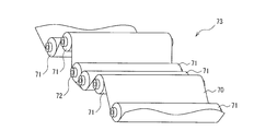
- FIG. 11 is a perspective view showing a part of the film transport device 73.
- the film 70 is supported and transported by a large number of transport rollers 71 arranged in parallel to each other. These transport rollers 71 rotate around a rotation shaft, and a rolling bearing 72 is attached to each rotation shaft.
- the conveyance roller 71 includes a driving roller that applies a driving force to the film 70 and a driven roller that rotates by a frictional force generated between the moving film 70. There are more follower rollers than drive rollers.
- the driven roller is arranged to smoothly convey the film 70 by changing the relative position of the front and rear rollers to change the angle in the vertical direction of the film surface.
- the driven roller is rotated only by the frictional force with the film 70 and the peripheral speed of the roller surface is the same as the traveling speed of the film 70. Therefore, the driven roller needs to start rotating with an extremely small force applied from the film 70 in the tangential direction of the driven roller, and needs to continue to rotate stably. Therefore, the rolling bearing 72 that supports the rotating shaft of the driven roller is required to have low dynamic friction torque and high durability. Deep groove ball bearings equipped with corrugated cages are widely used as rolling bearings, but because of their high dynamic friction torque, they are not suitable as rolling bearings 72 for this application.
- Patent Document 1 describes a bearing ring guide type cage that is made of synthetic resin, is formed in an annular shape, and includes a plurality of pocket portions that hold a plurality of rolling elements one by one in the circumferential direction.
- the cage material is a synthetic resin containing a solid lubricant with a bending elastic modulus and a dynamic friction coefficient within the specified ranges, which suppresses the torque increase of the rolling bearing and improves the durability performance. It is described to do.
- the flexural modulus of the material is in the range of 600 to 2000 MPa, and the dynamic friction coefficient is 0.2 or less.
- the annular shape of the cage is maintained, and the cage is prevented from being easily deformed during the rotation of the bearing to prevent the rotational performance from being deteriorated.
- the dynamic friction coefficient is reduced to suppress an increase in the dynamic friction torque of the bearing.
- the cage of the rolling bearing is made of synthetic resin
- the thickness (diameter in the radial direction of the ring) is thin
- the guide system is rolling element guide
- the roundness of the cage is received by the force from the rolling element. May deteriorate the rotational performance.
- Patent Document 2 straight pockets (pockets whose diameter does not change in the thickness direction) and ball guide pockets (different diameter pockets whose diameter changes in the thickness direction) are alternately arranged in the cage of the ball bearing. Further, it is described that the force from the ball is relaxed to reduce the deformation of the cage and suppress the torque increase. However, the technique described in Patent Document 2 can obtain the effect of suppressing an increase in the torque of the bearing only when the cage is a thin-walled bearing that is easily deformed or when the radial load applied to the bearing is large.
- An object of the present invention is to provide a rolling bearing having a dynamic friction torque reduced as compared with a conventional rolling bearing.
- a rolling bearing according to an aspect of the present invention is a rolling bearing having an inner ring, an outer ring, a plurality of rolling elements, and an annular cage, and the cage is PP or PP. It is formed by compressing and then machining a resin composition containing a copolymer (polypropylene or a copolymer of propylene and another olefin) as a main component and containing PTFE (polytetrafluoroethylene).
- a copolymer polypropylene or a copolymer of propylene and another olefin
- PTFE polytetrafluoroethylene
- the guide type of the cage is a bearing ring guide (inner ring guide or outer ring guide), and 1.0 g or more per 1 m 2 of the total surface area on the raceway surfaces of the inner and outer rings and the rolling surface of the rolling element.
- the lubricant is applied in an amount of 10 g or less (preferably 4.0 g or less).
- the amount of lubrication is 1.0 g or more and 10 g or less (preferably 4.0 g or less) per 1 m 2 of the total surface area on the raceway surfaces of the inner and outer rings and the rolling surfaces of the rolling elements. Since the agent is applied (trace lubrication is applied), the torque can be kept low.
- the cage is made of a resin composition containing PP or PP copolymer as a main component and containing PTFE, a small amount of lubrication is required as compared with a resin composition containing polyamide as a main component. The dynamic friction torque of the rolling bearing below can be reduced.
- Polyamide has been conventionally used as a material for cages made of synthetic resin.
- PTFE is excellent in water repellency
- the lubricant that adheres to the rolling elements in the pocket in a small amount of lubrication does not transfer to the pocket.
- the state where the lubricant adheres to the rolling elements is maintained.
- the state where the rolling element and the pocket surface are close to non-contact is maintained, and the frictional resistance between the rolling element and the cage under a small amount of lubrication is reduced.
- the cage is a resin composition containing PP or a PP copolymer as a main component and containing PTFE, which is formed by mechanical processing after compression molding, the same resin composition can be used only for compression molding. Compared with the formed cage, the dynamic friction torque of the rolling bearing can be reduced.
- the resin composition present in the vicinity of the mold surface at the time of molding becomes a skin layer (surface layer) of the molded product.
- the PTFE in the resin composition is usually aggregated in the skin layer of the molded product to form huge particles. It exists uniformly.
- the cage constituting the rolling bearing of this aspect is formed into a final cage shape by machining a molded product formed into, for example, a cylinder or a cylinder by compression molding. Therefore, the skin layer generated by compression molding is removed by machining, and a portion closer to the core than the skin layer appears as a pocket surface.
- PTFE which is a solid lubricant
- PTFE is present in an island shape with substantially the same particle size, so the water repellency of this part is uniform. It has become. And since the part immediately under this skin layer becomes a pocket surface, the water repellency of the pocket surface becomes uniform.
- the pocket surface Since the distance between the PTFEs present in the form of islands on the pocket surface is several tens to several hundreds of ⁇ m, the pocket surface has a large number of water repellent portions (positions where PTFE is present). The wet lubricant is repelled by the water-repellent part on the pocket surface and becomes particulate. Therefore, a large amount of the lubricant applied to the inside of the rolling bearing of this aspect is present as lubricant particles on the pocket surface. Since each of the lubricant particles has a static pressure, the pocket surface and the rolling element are less likely to contact each other. Therefore, in the rolling bearing of this aspect, the frictional resistance associated with the sliding between the cage pocket and the rolling element is reduced.
- the skin layer becomes the pocket surface, so PTFE aggregates on the pocket surface to form huge particles, which are unevenly present. That is, there may be a case where water repellent portions (positions where PTFE is present) are unevenly present on the pocket surface, or a pocket where there is no water repellent portion on the surface.
- the lubricant since it is unlikely that the lubricant is present on the pocket surface as the above-described lubricant particles, the rolling element and the pocket surface are likely to come into contact with each other, and friction caused by sliding between the cage pocket and the rolling element. Resistance increases.
- the rolling bearing of this aspect is such that the cage and the bearing ring (inner ring or outer ring) slide because the guide type of the cage is a bearing ring guide.
- the dynamic friction torque can be kept small. If the rolling bearing of this aspect has a number of rolling elements corresponding to 70% or more and 90% or less of the maximum number, the dynamic friction torque can be further reduced as compared with rolling bearings having other numbers of rolling elements. it can.
- the maximum number of rolling elements that a rolling bearing can have is determined by the dimensions of the inner and outer rings to be combined. Moreover, the number of rolling elements which a normal rolling bearing has is the maximum number. The reason is that the larger the number of rolling elements, the more easily the load applied to the rolling bearing is dispersed, which is advantageous in improving the life of the bearing due to metal fatigue.
- the smaller the number of rolling elements the smaller the number of elastic deformations of the inner and outer rings due to the passage of the rolling elements, so the dynamic friction torque of the rolling bearing decreases.
- the number of rolling elements is too small and the rolling element row becomes a polygon that cannot be approximated to a circle, the rotational performance of the rolling bearing is affected.
- the number of rolling elements is a number corresponding to 70% or more and 90% or less of the maximum number, the rotational performance of the rolling bearing can be satisfactorily maintained while reducing the dynamic friction torque.
- This thin bearing has a smaller outer diameter when the inner diameter is the same as that of the rolling bearing that does not satisfy the formula (1). Therefore, the bearing box can be made small. Further, in a film transport apparatus having a large number of driven rollers, adjacent driven rollers can be arranged closer to each other. Therefore, the installation area of the entire film transport apparatus can be reduced by using a thin bearing that satisfies the above equation (1) as the rolling bearing that supports the rotating shaft of the driven roller of the film transport apparatus.
- this thin-walled bearing has a narrow inner space in the radial direction compared to a rolling bearing that does not satisfy the formula (1), so that the diameter of the rolling elements to be arranged is small and the maximum number of rolling elements is large. Therefore, even if the reduction number from the maximum number of rolling elements is increased, the rotational performance of the rolling bearing is hardly affected. Therefore, when the rolling bearing of this aspect has the number of rolling elements corresponding to 70% or more and 90% or less of the maximum number, the deterioration of the rotational performance of the rolling bearing can be suppressed by satisfying the expression (1). .
- the rolling bearing of this aspect is suitable for an application for supporting the rotating shaft of a driven roller that rotates by a frictional force with a film in a film conveying device.
- the film transport apparatus include those having the following configurations (a) and (b).
- the conveying roller includes a driving roller that applies a driving force to the film, and a driven roller that rotates by a frictional force generated between the moving film.
- the rolling bearing of this aspect as a rolling bearing for supporting the driven roller of the film transport apparatus having the configurations (a) and (b), because of the advantages as described above.
- a rolling bearing having a kinetic friction torque reduced as compared with a conventional rolling bearing is provided.
- FIG. 1 It is sectional drawing which shows the rolling bearing of embodiment. It is a front view which shows the holder
- Drawing 1 is a sectional view showing the rolling bearing of an embodiment.
- the rolling bearing of this embodiment includes an inner ring 1, an outer ring 2, 15 balls (rolling elements) 3, a crown-shaped cage 4, and a shield plate 5.
- the maximum number of balls 3 in this rolling bearing is 21.
- An inner ring raceway groove (inner ring raceway surface) 12 is formed in the axially central portion of the outer peripheral surface 11 of the inner ring 1. Both end portions 13 in the axial direction of the outer peripheral surface 11 of the inner ring 1 are formed in small diameter portions having dimensions corresponding to the center holes 51 of the shield plate 5.
- An outer ring raceway groove (outer ring raceway surface) 22 is formed in the axially central portion of the inner peripheral surface 21 of the outer ring 2.
- Mounting grooves 23 for the shield plate 5 are formed at both axial ends of the inner peripheral surface 21 of the outer ring 2.
- the inner ring 1, the outer ring 2 and the ball 3 are made by a normal method using a material made of SUJ2 or SUS440C.
- the inner ring raceway groove 12, the outer ring raceway groove 22 and the surface (rolling surface) of the ball 3 are coated with an amount of lubricant of 1.0 g or more and 10 g or less per 1 m 2 of the total surface area (S).
- S total surface area
- a small amount of lubricant can be applied by dipping the inner ring raceway groove 12, the outer ring raceway groove 22 and the ball 3 in the lubricant and pulling them up, or by lubricating the inner ring raceway groove 12, the outer ring raceway groove 22 and the surface of the ball 3.
- This can be done by spraying the agent.
- the actual application amount can be calculated by dividing the mass difference between the rolling bearings before and after applying the lubricant by the total surface area S.
- the cage 4 is formed by using a resin composition containing PP or a PP copolymer as a main component and containing PTFE, and performing machining after compression molding.
- the cage 4 is an annular body including 15 pocket portions 41 at equal intervals in the circumferential direction.
- Each pocket portion 41 is open at one end in the axial direction of the torus.
- the opening dimension B of the opening 42 is smaller than the diameter of the ball 3 (see FIG. 1).
- the ball 3 is inserted into the pocket 41 by elastically deforming the opening 42. Thereby, the ball 3 is held without dropping from the pocket portion 41.
- Each pocket portion 41 of the cage 4 is composed of only the rolling element holding surface 41 a having a circular arc surface concentric with the ball 3.
- the guide type of the cage 4 is a bearing ring (inner ring in FIG. 1) guide, and the inner circumferential surface of the cage 4 and the outer circumferential surface 11 of the inner ring 1 slide.
- the shield plate 5 (see FIG. 1) is obtained by pressing a steel plate made of SPCC or SUS304.
- the rolling bearing of this embodiment is formed by subjecting a cage 4 to a micro lubrication, and machining the resin composition containing PTFE containing PP or a PP copolymer as a main component after compression molding. Therefore, although the guide type of the cage is a rolling bearing with a bearing ring guide, the rotational performance can be satisfactorily maintained while reducing the dynamic friction torque. Further, the dynamic friction torque can be further reduced by setting the number of balls 3 to 15 (71%) which is less than the maximum number of 21. In this embodiment, the ball bearing in which the rolling element is a ball has been described.
- the present invention is not limited to the ball bearing, and is applicable to a roller bearing in which the rolling element is a cylindrical or conical roller. it can.
- the rolling surface of the roller is a peripheral surface, the roller end surface is not included in the surface area of the rolling element included in the total surface area.
- Example 1 In Example 1, the difference in the dynamic friction torque of the rolling bearing and the number of particles generated due to the difference in the material of the cage and the amount of lubricant was examined.
- the inner ring 1 and the outer ring 2 are made of SUJ2 and manufactured by a normal method.
- the ball 3 is made of SUJ2 and produced by a normal method.
- the number of balls 3 is eight as usual (maximum number).
- the shield plate 5 is obtained by press forming a steel plate made of SPCC.
- a thing (cage B) was prepared.
- PP copolymer an ethylene / propylene copolymer "Sun Allomer PB222A” manufactured by Sun Allomer Co., Ltd.
- PTFE “7A” manufactured by Mitsui DuPont Fluorochemical, average particle size of 34 ⁇ m
- Nylon 66 “UBE nylon 66” manufactured by Ube Industries
- Carbon fiber “Kureka chop M-102S” manufactured by Kureha Chemical Industry Co., Ltd., an average fiber diameter of 14.5 ⁇ m, and a length of 0.2 mm
- a lithium grease for clean room (“LG2” manufactured by NSK Ltd.) was prepared.
- an amount of grease corresponding to 30% by volume of the bearing space was filled, and four bearings using the cages A and B were assembled.
- the test apparatus shown in FIG. 3 was tested by attaching two rolling bearings each having the same cage as the test bearing 61. Two bearings with four cages A were attached and the first test was conducted, and the remaining two were attached and the second test was conducted. Similarly, two of the bearings to which four cages B were attached were attached to perform the first test, and the remaining two were attached to perform the second test.
- the test apparatus shown in FIG. 3 is attached to a rotary drive device (not shown), and has a rotary shaft 60 disposed horizontally, a bearing holder 62 disposed between two test bearings 61, a preload spring 63, and one end. It has the thread
- the inner rings of the two test bearings 61 are attached to the rotary shaft 60, and the bearing holder 62 is fitted on the outer ring.
- a preload load (axial load) is applied to the inner ring by a preload spring 63.
- the thread 64 extends in a tangential direction from an intermediate point between the outer rings of the two test bearings 61.
- the outer ring of the test bearing 61 When the inner ring of the test bearing 61 is rotated by the rotation of the rotating shaft 60, the outer ring is rotated by friction. This accompanying tangential force (tangential load) is measured by a force gauge 65. Since the measured value is the value of the two test bearings 61, one value is calculated by dividing by two. Then, the dynamic friction torque value is calculated by multiplying the measured value of the tangential force by the radius of the bearing holder 62.
- the normal value of the dynamic friction torque value (converted value from the tangential force) at the time when the rotating shaft 60 is rotated in one direction at room temperature, normal pressure, and a rotational speed of 150 min ⁇ 1 and 15 minutes have elapsed, and The amount of deflection (b in FIG. 4) was examined, and the result is shown in the graph of FIG.
- the load conditions are a preload load (axial load) of 88.2 N (9 kgf) by the preload spring 63 and a load (radial load) by the weight of the housing.
- the cage A is used to apply grease in an amount of 1.0 g, 10.0 g, and 11.0 g per 1 m 2 of the total surface area of the inner ring raceway groove 12, outer ring raceway groove 22, and ball 3. Then, two bearings were assembled. Further, using the cage B, grease of an amount of 1.0 g and 10.0 g per 1 m 2 of the total surface area is applied to the surfaces of the inner ring raceway groove 12, the outer ring raceway groove 22 and the ball 3. Individual bearings were assembled.
- the coating amount of the lubricant in comparison to the case of 10.0 g / m 2 and 11.0 g / m 2, the difference in coating amount of 1.0 g / m 2 Despite the quantity, the difference in the nominal value of the dynamic friction torque is large.
- the bearing with a coating amount of 11.0 g / m 2 is about 30 N ⁇ mm, which is significantly larger than the bearing with a coating amount of 10.0 g / m 2 less than 20 N ⁇ mm.
- a cylindrical protrusion 821 of the rotating body 82 is fitted on an annular portion 831 formed at one end of the rotating shaft 83.
- the other end side of the rotating shaft 83 is connected to a motor 83b through a coupling 83a.
- the rotating shaft 83 is horizontally disposed and is rotatably attached to the housing 88 by support bearings 87 disposed at two positions in the longitudinal direction.
- the test bearing 81 is present in the sealed space 9 formed by the cylinder 91 made of acrylic, the front plate 92, and the partition plate 93.
- a clean air introduction port 94 and a discharge port 95 are formed in the front plate 92 of the sealed space 9.
- a magnetic seal 89 is disposed between the annular portion 831 of the rotary shaft 83 and the annular body 881 fixed to the housing 88 of the support bearing 87. That is, the magnetic seal 89 seals between the housing 84 of the test bearing 81 and the housing 88 of the support bearing 87. As a result, particles from the support bearing 87 generated as the rotating shaft 83 rotates and particles in the atmosphere passing through the inside of the support bearing 87 and the fitting portion do not enter the sealed space 9. ing.
- the rotary shaft 83 is connected with a pipe for introducing clean air (standard air containing no particles) connected to the inlet 94 and a pipe directed to the air inlet of the particle counter connected to the outlet 95. Rotate. At that time, the gas in the sealed space 9 is discharged from the outlet 95 toward the particle counter, and clean air having the same volume as the discharged gas is introduced from the inlet 94.
- clean air standard air containing no particles
- the rotating shaft 83 is rotated in one direction under the conditions of normal temperature, normal pressure, an axial load of 29.4 N (3.0 kgf), and a rotation speed of 1700 min ⁇ 1 , and 1 CF in the sealed space 9 is provided every predetermined number of rotations.
- the number of particles per (cubic foot) (thickness of 0.1 ⁇ m or less) was continuously measured 5 times. The value with the smallest number among the five measurement results was plotted in the graph of FIG.
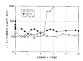
- the number of particles generated from the bearings with the lubricant application amounts of 1.0 g / m 2 and 10.0 g / m 2 is from 1 ⁇ 10 7 times to 10 ⁇ 10 7 There was no significant change up to 7 times, and it was 300 pieces / CF or less. If the number of particles of 0.1 ⁇ m or less is 350 / CF or less, it corresponds to class 10 in the standard of FED-STD-209. Therefore, it can be seen that the bearings with the lubricant application amounts of 1.0 g / m 2 and 10.0 g / m 2 have high cleanliness.
- Example 2 the difference in the dynamic friction torque of the rolling bearing and the number of particles generated due to the difference in the number of rolling elements was examined.
- the inner ring 1 and the outer ring 2 are made of SUJ2 and manufactured by a normal method.
- the ball 3 is made of SUJ2 and produced by a normal method.
- the number of balls 3 is 21 (maximum number), 20 (95.2% of the maximum number), 19 (90.5% of the maximum number), 18 (85.7% of the maximum number), 17 (81.0% of maximum number), 16 (76.2% of maximum number), 15 (71.4% of maximum number), 14 (66.7% of maximum number), 13 12 types (61.9% of maximum number), 12 (57.1% of maximum number), 11 (52.3% of maximum number), 10 (47.6% of maximum number) .
- the shield plate 5 is obtained by press forming a steel plate made of SPCC.
- the number of pocket portions 41 of the cage 4 is Z, and in a sample in which the number of balls 3 is smaller than Z, the balls 3 are not put in a part of the pocket portions 41 of the cage 4. At that time, the plurality of balls 3 were arranged evenly in the circumferential direction of the cage 4 as much as possible.
- these bearings were tested on the test apparatus shown in FIG. 3 by attaching two rolling bearings having the same cage as the test bearing 61 and examining the dynamic friction torque of the test bearing 61. .
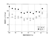
- the nominal value (a in FIG. 4) of the dynamic friction torque value (converted value from the tangential force) at the time when the rotating shaft 60 is rotated in one direction at room temperature, normal pressure, and rotational speed 70 min ⁇ 1 and 15 minutes have passed.
- the results are shown in the graph of FIG.
- the load conditions are a preload (axial load) of 88.2 N (16 kgf) by the preload spring 63 and a load (radial load) of 4.9 N (500 gf) by the weight of the housing.
- the rolling element loading ratio (ratio when Z is set to 100) decreases, the dynamic friction torque value decreases to about 60%. Yes.
- the reason for starting to rise is presumed to be that the rotational performance of the rolling bearing decreases with the polygonalization of the rolling element rows.
- the result is that the lubricant application amount is 1 It can be said that setting the rolling element loading rate in the range of 0.0 to 10.0 g / m 2 to 70% or more and 90% or less is effective in reducing the dynamic friction torque value.
- the inner ring 1, the outer ring 2, the ball 3, the cage 4, and the shield plate 5 were the same as those used for the dynamic friction torque test.
- the number of balls 3 is 21 (maximum number), 19 (90.5% of the maximum number), 17 (81.0% of the maximum number), 15 (71.4% of the maximum number), There were 6 types of 13 pieces (61.9% of the maximum number) and 11 pieces (52.3% of the maximum number).
- test bearing 81 of the particle measuring apparatus shown in FIG. 7, and the number of particles generated by the rotation of the test bearing 81 was measured by the same method as in Example 1.
- the test conditions were normal temperature, normal pressure, rotational speeds 70 min ⁇ 1 and 300 min ⁇ 1 , a preload load (axial load) of 88.2 N (16 kgf) by the preload spring 63 and a load of 4.9 N (500 gf) by the weight of the housing. (Radial load).
- the number of particles per 1 CF (cubic foot) in the sealed space 9 was continuously measured five times.
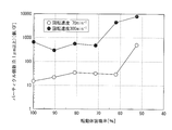
- the value of the smallest number among the five measurement results was plotted in the graph of FIG. 10 for each rotation speed.
- the number of particles rapidly increases when the rolling element loading rate becomes smaller than 70%. This is presumed to be due to a decrease in the rotational performance of the rolling bearing accompanying the polygonalization of the rolling element rows. From this result, it can be said that when the application amount of the lubricant is 1.0 g / m 2 , a rolling element loading rate of 70% or more is preferable.
Landscapes
- Engineering & Computer Science (AREA)
- General Engineering & Computer Science (AREA)
- Mechanical Engineering (AREA)
- Rolling Contact Bearings (AREA)
- Rolls And Other Rotary Bodies (AREA)
Description
搬送ローラ71には、フィルム70に駆動力を与える駆動ローラと、移動するフィルム70との間に生じる摩擦力で回転する従動ローラがある。駆動ローラよりも従動ローラの数の方が多い。従動ローラは、前後のローラとの相対位置を変えてフィルム面の上下方向での角度を変えたりすることで、フィルム70を円滑に搬送するために配置されている。
波形保持器を備えた深溝玉軸受は転がり軸受として広く使用されているが、動摩擦トルクが高いため、この用途の転がり軸受72としては不向きである。
一方、転がり軸受の保持器が、合成樹脂製で、厚さ(円環の径方向寸法)が薄く、案内方式が転動体案内であると、転動体からの力を受けて保持器の真円性が悪くなり、回転性能に悪影響を及ぼすことがある。
しかしながら、特許文献2に記載された技術で軸受のトルク上昇を抑える効果が得られるのは、保持器が変形し易い薄肉軸受の場合か、軸受にかかるラジアル荷重が大きい場合などに限られる。
また、保持器は、PPまたはPP共重合体を主成分とし、PTFEを含有する樹脂組成物からなるものであるため、ポリアミドを主成分とする樹脂組成物からなるものと比較して、微量潤滑下での転がり軸受の動摩擦トルクを低減できる。ポリアミドは合成樹脂製保持器の材料として従来より使用されている。
圧縮成形の場合、成型時に金型表面近傍に存在していた樹脂組成物が、成形品のスキン層(表面層)となる。PPまたはPP共重合体を主成分としPTFEを含有する樹脂組成物を圧縮成形した場合、通常、成形品のスキン層には、樹脂組成物中のPTFEが凝集し、巨大な粒となって不均一に存在する。
この態様の転がり軸受が、最大個数の70%以上90%以下に相当する数の転動体を有すると、これ以外の数の転動体を有する転がり軸受と比較して動摩擦トルクをさらに小さくすることができる。
((D-d)/2)/t≦1.07‥‥(1)
(a)互いに平行に配置され、フィルムを支持しながら搬送する複数の搬送ローラと、前記搬送ローラの回転軸を支持する転がり軸受と、を有する。
(b)前記搬送ローラは、フィルムに駆動力を与える駆動ローラと、移動するフィルムとの間に生じる摩擦力で回転する従動ローラと、からなる。
図1は、実施形態の転がり軸受を示す断面図である。
この実施形態の転がり軸受は、内輪1、外輪2、15個のボール(転動体)3、冠形の保持器4、およびシールド板5とで構成されている。この転がり軸受におけるボール3の最大個数は21個である。
内輪軌道溝12と外輪軌道溝22とボール3の表面(転動面)に、これらの合計表面積(S)1m2当たり1.0g以上10g以下となる量の潤滑剤が塗布されている。このように微量な潤滑剤の塗布は、内輪軌道溝12と外輪軌道溝22とボール3を潤滑剤に浸漬して引き上げる方法や、内輪軌道溝12と外輪軌道溝22とボール3の表面に潤滑剤を噴霧する方法で行うことができる。また、実際の塗布量は、潤滑剤塗布前後の転がり軸受の質量差を合計表面積Sで除算することで算出できる。
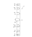
保持器4は、図2に示すように、円周方向に等間隔で15個のポケット部41を備えた円環体である。各ポケット部41は、円環体の軸方向一端が開口している。この開口部42の開口寸法Bはボール3(図1参照)の直径より小さく形成されている。ボール3は、開口部42を弾性変形させてポケット部41に挿入される。これにより、ボール3はポケット部41から脱落せずに保持される。保持器4の各ポケット部41は、ボール3と同心の円弧面状の転動体保持面41aのみからなる。
保持器4の案内形式は軌道輪(図1では内輪)案内であり、保持器4の内周面と内輪1の外周面11とは摺動する。
この実施形態の転がり軸受は、微量潤滑を施し、保持器4を、PPまたはPP共重合体を主成分としてPTFEを含有する樹脂組成物を圧縮成形後に機械加工することで形成している。そのため、保持器の案内形式が軌道輪案内の転がり軸受ではあるが、動摩擦トルクを低減しながら、回転性能を良好に保持することができる。また、ボール3の個数を最大個数である21個より少ない15個(71%)とすることにより、更に動摩擦トルクを低減することができる。 なお、この実施形態では、転動体がボールである玉軸受について説明したが、この発明は玉軸受に限定されず、転動体が円柱状や円錐状のころ(ローラ)であるころ軸受にも適用できる。ころ軸受の場合、ころの転動面は周面であるため、合計表面積に算入する転動体の表面積にころの端面は含まない。
実施例1では、保持器の材質及び潤滑剤量の違いによる、転がり軸受の動摩擦トルク及びパーティクル発生個数の違いを調べた。
<動摩擦トルク試験>
図1の転がり軸受として呼び番号6200の深溝玉軸受を用い、下記の方法で動摩擦トルクを調べる試験を行った。各寸法は、図1に示す軸受内径d=10mm、軸受外径D=32mm、軸受幅t=9mmである。
保持器4としては、図2と同様の形状であるが、ポケット数は8個であり、PP共重合体とPTFEからなる樹脂組成物(質量比でPP共重合体:PTFE=90:10)を圧縮成形後、機械加工により得られたもの(保持器A)と、ナイロン66とカーボン繊維からなる樹脂組成物(質量比でナイロン66:カーボン繊維=85:15)の射出成形により得られたもの(保持器B)を用意した。
PTFE:三井デュポンフロロケミカル製「7A」、平均粒径34μm
ナイロン66:宇部興産製「UBEナイロン66」
カーボン繊維:呉羽化学工業製「クレカチョップM-102S」、平均繊維径14.5μm、長さ0.2mm グリースとしては、クリーンルーム対応リチウム系グリース(日本精工製「LG2」)を用意した。
図3に示す試験装置に、試験軸受61として、保持器が同じ転がり軸受を2個ずつ取り付けて試験を行った。4個ある保持器Aが取り付けられた軸受の2個を取り付けて1回目の試験を行い、残りの2個を取り付けて2回目の試験を行った。同様に、4個ある保持器Bが取り付けられた軸受の2個を取り付けて1回目の試験を行い、残りの2個を取り付けて2回目の試験を行った。
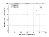
図6のグラフに示すように、潤滑剤の塗布量が同じ場合、保持器A(PP保持器:主材料がPP共重合体でPTFEを含有)を備えた軸受のプロットは、保持器B(PA保持器:主材料がナイロン66でカーボン繊維を含有)を備えた軸受のプロットより、左下隅に近い位置にある。すなわち、保持器をPTFE含有PP共重合体製とすることで、カーボン繊維含有ナイロン66製とした場合よりも、微量潤滑下での動摩擦トルク値を小さくできることが分かる。
保持器Aを用い、内輪軌道溝12と外輪軌道溝22とボール3の表面に、これらの合計表面積1m2当たり0.75g、1.0g、10.0gとなる量のグリース(日本精工製「LG2」)を塗布して、各1個の軸受を組み立てた。
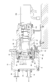
これらの軸受を図7に示すパーティクル測定装置の試験軸受81として取り付けて、試験軸受81の回転により生じるパーティクル数を測定した。
図7の測定装置は、試験軸受81の内輪に内嵌される回転体82と、一端が回転体82にボルトで固定された回転軸83と、試験軸受81のハウジング84と、試験軸受81の外輪にアキシャル荷重を加えるための環状体85およびバネ86を有する。
試験軸受81は、アクリル製の筒体91、前面板92、および仕切り板93で形成された密閉空間9内に存在する。密閉空間9の前面板92に、クリーンエアの導入口94と導出口95が形成されている。
この結果から、潤滑剤塗布量として、内輪軌道溝12と外輪軌道溝22とボール3の合計表面積1m2当たり1.0gが、微量潤滑下での動摩擦トルク値を小さくしながら6×10⁷回転の軸受寿命が得られるための下限値と言うことができる。
実施例2では、転動体の数の違いによる、転がり軸受の動摩擦トルクおよびパーティクル発生個数の違いを調べた。
<動摩擦トルク試験>
図1の転がり軸受として呼び番号6812の深溝玉軸受を用い、下記の方法で動摩擦トルクを調べる試験を行った。各寸法は、軸受内径d=60mm、軸受外径D=78mm、軸受幅t=10mmであり、A=((D-d)/2)=9mm、A/t=0.9である。すなわち、この転がり軸受は上記(1) 式を満たす。
ボール3の個数が異なる12種類の転がり軸受について、内輪軌道溝12と外輪軌道溝22とボール3の表面に、これらの合計表面積1m2当たり1.0g、10.0gとなる量の潤滑剤(実施例1と同じクリーンルーム対応リチウム系グリース)を塗布して、同じ構成の転がり軸受(24種類)を2個ずつ組み立てた。保持器4のポケット部41の数はZ個であり、ボール3の個数がZより少ないサンプルでは、保持器4のポケット部41の一部にボール3を入れない。その際に、複数個のボール3が極力、保持器4の円周方向に均等に配置されるようにした。
常温、常圧、回転速度70min-1で、回転軸60を一方向に回転し、15分経過した時点での動摩擦トルク値(接線力からの換算値)のノミナル値(図4のa)を調べて、その結果を図9のグラフに示した。荷重条件は、予圧バネ63による88.2N(16kgf)の予圧荷重(アキシアル荷重)と、ハウジング自重による4.9N(500gf)の荷重(ラジアル荷重)である。
そして、潤滑剤の塗布量が1.0g/m2の場合と10.0g/m2の場合で上昇に転じる転動体装填率に差はあるが、この結果から、潤滑剤の塗布量が1.0~10.0g/m2の範囲で転動体装填率を70%以上90%以下とすることが、動摩擦トルク値の低下に有効であると言うことができる。
内輪1、外輪2、ボール3、保持器4、およびシールド板5は、動摩擦トルク試験用と同じものを使用した。
ボール3の数は、それぞれ21個(最大個数)、19個(最大個数の90.5%)、17個(最大個数の81.0%)、15個(最大個数の71.4%)、13個(最大個数の61.9%)、11個(最大個数の52.3%)の6種類とした。
ボール3の個数が異なる6種類の転がり軸受について、内輪軌道溝12と外輪軌道溝22とボール3の表面に、これらの合計表面積1m2当たり1.0gとなる量の潤滑剤(実施例1と同じクリーンルーム対応リチウム系グリース)を塗布して、同じ構成の転がり軸受(6種類)を2個ずつ組み立てた。
図10のグラフに示すように、回転速度が70min-1および300min-1のいずれの場合も、転動体装填率が70%よりも小さくなるとパーティクル個数が急増している。これは、転動体列の多角形化に伴い転がり軸受の回転性能が低下したことに起因すると推測される。この結果から、潤滑剤の塗布量が1.0g/m2の場合は、転動体装填率70%以上が好ましいと言うことができる。
11 内輪の外周面
12 内輪軌道溝
2 外輪
21 外輪の内周面
22 外輪軌道溝
23 シールド板の取り付け溝
3 ボール(転動体)
4 保持器
41 ポケット部
41a 転動体保持面
42 開口部
5 シールド板
60 回転軸
61 試験軸受
62 軸受ホルダー
63 予圧バネ
64 糸
65 フォースゲージ
70 フィルム
71 搬送ローラ
72 転がり軸受
73 フィルム搬送装置
81 試験軸受
82 回転体
821 回転体の円柱状突起
83 回転軸
831 回転軸の環状部
83a カップリング
83b モータ
84 ハウジング
85 環状体
86 バネ
87 サポート軸受
88 ハウジング
881 環状体
89 磁気シール
9 密閉空間
91 筒体
92 前面板
93 仕切り板
94 導入口
95 導出口
Claims (5)
- 内輪、外輪、複数の転動体、および円環状の保持器を有し、
前記保持器は、PPまたはPP共重合体(ポリプロピレンまたはプロピレンと他のオレフィンとの共重合体)を主成分とし、PTFE(ポリテトラフルオロエチレン)を含有する樹脂組成物を圧縮成形後、機械加工することで形成されたものであり、
前記保持器の案内形式は軌道輪案内であり、 前記内輪および外輪の軌道面と前記転動体の転動面に、これらの合計表面積1m2当たり1.0g以上10g以下となる量の潤滑剤が塗布されていることを特徴とする転がり軸受。 - 前記転動体の数が、最大個数の70%以上90%以下に相当する数である請求項1記載の転がり軸受。
- 軸受内径をd、軸受外径をD、軸受幅をtとした時、下記の(1)式を満たす請求項1または2記載の転がり軸受。
((D-d)/2)/t≦1.07‥‥(1) - フィルム搬送装置でフィルムとの摩擦力で回転する従動ローラの回転軸を支持する用途で使用される請求項1~3のいずれか1項に記載の転がり軸受。
- 請求項1~3のいずれか1項に記載された転がり軸受を備えているフィルム搬送装置。
Priority Applications (1)
| Application Number | Priority Date | Filing Date | Title |
|---|---|---|---|
| DE212012000269.3U DE212012000269U1 (de) | 2012-03-16 | 2012-08-21 | Wälzlager und Folientransportvorrichtung |
Applications Claiming Priority (2)
| Application Number | Priority Date | Filing Date | Title |
|---|---|---|---|
| JP2012060042 | 2012-03-16 | ||
| JP2012-060042 | 2012-03-16 |
Publications (1)
| Publication Number | Publication Date |
|---|---|
| WO2013136379A1 true WO2013136379A1 (ja) | 2013-09-19 |
Family
ID=49160354
Family Applications (1)
| Application Number | Title | Priority Date | Filing Date |
|---|---|---|---|
| PCT/JP2012/005226 Ceased WO2013136379A1 (ja) | 2012-03-16 | 2012-08-21 | 転がり軸受及びフィルム搬送装置 |
Country Status (3)
| Country | Link |
|---|---|
| JP (1) | JPWO2013136379A1 (ja) |
| DE (1) | DE212012000269U1 (ja) |
| WO (1) | WO2013136379A1 (ja) |
Families Citing this family (1)
| Publication number | Priority date | Publication date | Assignee | Title |
|---|---|---|---|---|
| DE102018126579A1 (de) * | 2018-10-25 | 2019-04-25 | Schaeffler Technologies AG & Co. KG | Axialwälzlager |
Citations (5)
| Publication number | Priority date | Publication date | Assignee | Title |
|---|---|---|---|---|
| JP2007298054A (ja) * | 2006-04-27 | 2007-11-15 | Nsk Ltd | 高温環境用転がり軸受 |
| JP2011047500A (ja) * | 2009-08-28 | 2011-03-10 | Nsk Ltd | 転がり軸受 |
| JP2011226623A (ja) * | 2010-04-23 | 2011-11-10 | Nsk Ltd | 搬送ローラ用転がり軸受 |
| JP2012021610A (ja) * | 2010-07-15 | 2012-02-02 | Nsk Ltd | 搬送ローラ用転がり軸受 |
| JP2012067912A (ja) * | 2010-08-23 | 2012-04-05 | Nsk Ltd | 転がり軸受 |
-
2012
- 2012-08-21 DE DE212012000269.3U patent/DE212012000269U1/de not_active Expired - Lifetime
- 2012-08-21 WO PCT/JP2012/005226 patent/WO2013136379A1/ja not_active Ceased
- 2012-08-21 JP JP2013509344A patent/JPWO2013136379A1/ja active Pending
Patent Citations (5)
| Publication number | Priority date | Publication date | Assignee | Title |
|---|---|---|---|---|
| JP2007298054A (ja) * | 2006-04-27 | 2007-11-15 | Nsk Ltd | 高温環境用転がり軸受 |
| JP2011047500A (ja) * | 2009-08-28 | 2011-03-10 | Nsk Ltd | 転がり軸受 |
| JP2011226623A (ja) * | 2010-04-23 | 2011-11-10 | Nsk Ltd | 搬送ローラ用転がり軸受 |
| JP2012021610A (ja) * | 2010-07-15 | 2012-02-02 | Nsk Ltd | 搬送ローラ用転がり軸受 |
| JP2012067912A (ja) * | 2010-08-23 | 2012-04-05 | Nsk Ltd | 転がり軸受 |
Also Published As
| Publication number | Publication date |
|---|---|
| DE212012000269U1 (de) | 2014-11-20 |
| JPWO2013136379A1 (ja) | 2015-07-30 |
Similar Documents
| Publication | Publication Date | Title |
|---|---|---|
| EP1847727B1 (en) | Thin-wall bearing | |
| JP5935370B2 (ja) | ころ軸受 | |
| EP2458237A1 (en) | Roller bearing and process for producing same | |
| CN103429916A (zh) | 滚子轴承 | |
| JP2014095469A (ja) | 転がり軸受 | |
| KR100281621B1 (ko) | 무리테이너형 구름 베어링 | |
| EP2088342A1 (en) | Rolling bearing and total rolling element bearing | |
| CN112739922B (zh) | 滚动轴承以及风力发电用主轴支承装置 | |
| JP5838647B2 (ja) | 転がり軸受 | |
| JPWO2013118202A1 (ja) | 転がり軸受およびフィルム搬送装置 | |
| WO2013136379A1 (ja) | 転がり軸受及びフィルム搬送装置 | |
| JP5310391B2 (ja) | 転がり軸受、搬送ロボット及びフィルム搬送装置 | |
| US20130170780A1 (en) | Roller Bearing and Method for Manufacturing the Same | |
| CN105952794B (zh) | 直线运动轴承 | |
| CN100529448C (zh) | 薄壁轴承 | |
| JP5594386B2 (ja) | 転がり軸受、搬送ロボット及びフィルム搬送装置 | |
| Kröner et al. | Greenbearings–friction behaviour of DLC-coated dry running deep groove ball bearings | |
| JP2013076469A (ja) | 転がり摺動部材及び転がり軸受並びに転がり摺動部材の製造方法 | |
| JP2010190390A (ja) | 転がり摺動部材及び転がり軸受並びに転がり摺動部材の製造方法 | |
| JP2011226623A (ja) | 搬送ローラ用転がり軸受 | |
| JP6855974B2 (ja) | 転がり軸受及びその製造方法 | |
| US20240125351A1 (en) | Thrust needle roller bearing | |
| JP2008019965A (ja) | 遊星歯車装置及び転がり軸受 | |
| JP2005023965A (ja) | 真空装置用搬送ローラー | |
| JP2006266405A (ja) | 転がり軸受及びその製造方法 |
Legal Events
| Date | Code | Title | Description |
|---|---|---|---|
| ENP | Entry into the national phase |
Ref document number: 2013509344 Country of ref document: JP Kind code of ref document: A |
|
| 121 | Ep: the epo has been informed by wipo that ep was designated in this application |
Ref document number: 12870939 Country of ref document: EP Kind code of ref document: A1 |
|
| WWE | Wipo information: entry into national phase |
Ref document number: 2120120002693 Country of ref document: DE Ref document number: 212012000269 Country of ref document: DE |
|
| 122 | Ep: pct application non-entry in european phase |
Ref document number: 12870939 Country of ref document: EP Kind code of ref document: A1 |