WO2013133238A1 - Electrolyte film - electrode assembly - Google Patents
Electrolyte film - electrode assembly Download PDFInfo
- Publication number
- WO2013133238A1 WO2013133238A1 PCT/JP2013/055902 JP2013055902W WO2013133238A1 WO 2013133238 A1 WO2013133238 A1 WO 2013133238A1 JP 2013055902 W JP2013055902 W JP 2013055902W WO 2013133238 A1 WO2013133238 A1 WO 2013133238A1
- Authority
- WO
- WIPO (PCT)
- Prior art keywords
- layer
- anode
- gas diffusion
- cathode
- catalyst
- Prior art date
Links
Images


Classifications
-
- H—ELECTRICITY
- H01—ELECTRIC ELEMENTS
- H01M—PROCESSES OR MEANS, e.g. BATTERIES, FOR THE DIRECT CONVERSION OF CHEMICAL ENERGY INTO ELECTRICAL ENERGY
- H01M8/00—Fuel cells; Manufacture thereof
- H01M8/10—Fuel cells with solid electrolytes
- H01M8/1004—Fuel cells with solid electrolytes characterised by membrane-electrode assemblies [MEA]
-
- H—ELECTRICITY
- H01—ELECTRIC ELEMENTS
- H01M—PROCESSES OR MEANS, e.g. BATTERIES, FOR THE DIRECT CONVERSION OF CHEMICAL ENERGY INTO ELECTRICAL ENERGY
- H01M8/00—Fuel cells; Manufacture thereof
- H01M8/02—Details
- H01M8/0202—Collectors; Separators, e.g. bipolar separators; Interconnectors
- H01M8/023—Porous and characterised by the material
- H01M8/0234—Carbonaceous material
-
- H—ELECTRICITY
- H01—ELECTRIC ELEMENTS
- H01M—PROCESSES OR MEANS, e.g. BATTERIES, FOR THE DIRECT CONVERSION OF CHEMICAL ENERGY INTO ELECTRICAL ENERGY
- H01M8/00—Fuel cells; Manufacture thereof
- H01M8/02—Details
- H01M8/0202—Collectors; Separators, e.g. bipolar separators; Interconnectors
- H01M8/023—Porous and characterised by the material
- H01M8/0241—Composites
- H01M8/0243—Composites in the form of mixtures
-
- H—ELECTRICITY
- H01—ELECTRIC ELEMENTS
- H01M—PROCESSES OR MEANS, e.g. BATTERIES, FOR THE DIRECT CONVERSION OF CHEMICAL ENERGY INTO ELECTRICAL ENERGY
- H01M8/00—Fuel cells; Manufacture thereof
- H01M8/02—Details
- H01M8/0202—Collectors; Separators, e.g. bipolar separators; Interconnectors
- H01M8/023—Porous and characterised by the material
- H01M8/0241—Composites
- H01M8/0245—Composites in the form of layered or coated products
-
- H—ELECTRICITY
- H01—ELECTRIC ELEMENTS
- H01M—PROCESSES OR MEANS, e.g. BATTERIES, FOR THE DIRECT CONVERSION OF CHEMICAL ENERGY INTO ELECTRICAL ENERGY
- H01M8/00—Fuel cells; Manufacture thereof
- H01M8/04—Auxiliary arrangements, e.g. for control of pressure or for circulation of fluids
- H01M8/04082—Arrangements for control of reactant parameters, e.g. pressure or concentration
- H01M8/04089—Arrangements for control of reactant parameters, e.g. pressure or concentration of gaseous reactants
- H01M8/04119—Arrangements for control of reactant parameters, e.g. pressure or concentration of gaseous reactants with simultaneous supply or evacuation of electrolyte; Humidifying or dehumidifying
-
- H—ELECTRICITY
- H01—ELECTRIC ELEMENTS
- H01M—PROCESSES OR MEANS, e.g. BATTERIES, FOR THE DIRECT CONVERSION OF CHEMICAL ENERGY INTO ELECTRICAL ENERGY
- H01M8/00—Fuel cells; Manufacture thereof
- H01M8/10—Fuel cells with solid electrolytes
- H01M2008/1095—Fuel cells with polymeric electrolytes
-
- H—ELECTRICITY
- H01—ELECTRIC ELEMENTS
- H01M—PROCESSES OR MEANS, e.g. BATTERIES, FOR THE DIRECT CONVERSION OF CHEMICAL ENERGY INTO ELECTRICAL ENERGY
- H01M2300/00—Electrolytes
- H01M2300/0017—Non-aqueous electrolytes
- H01M2300/0065—Solid electrolytes
- H01M2300/0082—Organic polymers
-
- Y—GENERAL TAGGING OF NEW TECHNOLOGICAL DEVELOPMENTS; GENERAL TAGGING OF CROSS-SECTIONAL TECHNOLOGIES SPANNING OVER SEVERAL SECTIONS OF THE IPC; TECHNICAL SUBJECTS COVERED BY FORMER USPC CROSS-REFERENCE ART COLLECTIONS [XRACs] AND DIGESTS
- Y02—TECHNOLOGIES OR APPLICATIONS FOR MITIGATION OR ADAPTATION AGAINST CLIMATE CHANGE
- Y02E—REDUCTION OF GREENHOUSE GAS [GHG] EMISSIONS, RELATED TO ENERGY GENERATION, TRANSMISSION OR DISTRIBUTION
- Y02E60/00—Enabling technologies; Technologies with a potential or indirect contribution to GHG emissions mitigation
- Y02E60/30—Hydrogen technology
- Y02E60/50—Fuel cells
Definitions
- the present invention relates to an electrolyte membrane-electrode assembly.
- the present invention relates to an electrolyte membrane-electrode assembly used in a polymer electrolyte fuel cell (PEFC).
- PEFC polymer electrolyte fuel cell
- Fuel cells have attracted attention as vehicle drive sources and stationary power sources in response to social demands and trends in the background of energy and environmental problems.
- Fuel cells are classified into various types according to the type of electrolyte, the type of electrode, etc., representative of which are alkaline type, phosphoric acid type, molten carbonate type, solid electrolyte type and solid polymer type.
- a polymer electrolyte fuel cell (PEFC) capable of operating at low temperature (usually 100 ° C. or less) attracts attention, and in recent years, development and commercialization as a low pollution power source for automobiles are progressing.
- PEFC polymer electrolyte fuel cell
- the PEFC generally has a structure in which a membrane-electrode assembly (MEA) is sandwiched by separators.
- MEA membrane-electrode assembly
- An MEA generally has a structure in which a cathode gas diffusion layer (GDL), a cathode catalyst layer, a solid polymer electrolyte membrane, an anode catalyst layer, and an anode gas diffusion layer are stacked.
- the following electrochemical reactions proceed.
- hydrogen contained in the fuel gas supplied to the anode (fuel electrode) side is oxidized by the catalyst to become protons and electrons.
- the generated protons pass through the polymer electrolyte contained in the anode side catalyst layer and the solid polymer electrolyte membrane in contact with the anode side catalyst layer to reach the cathode (air electrode) side catalyst layer.
- electrons generated in the anode side catalyst layer are a conductive carrier constituting the anode side catalyst layer, a gas diffusion layer in contact with the side different from the solid polymer electrolyte membrane of the anode side catalyst layer, and a gas separator And reach the cathode side catalyst layer through an external circuit.
- Patent Document 1 a water retention layer that enhances the retention of water is provided between the electrode catalyst layer and the gas diffusion layer.
- the present invention has been made in view of the above-mentioned circumstances, and an object thereof is to provide an electrolyte membrane-electrode assembly capable of achieving both dryout resistance and flooding resistance.
- the present invention by providing the anode fine porous layer having a small relative gas diffusion coefficient on the anode side, water retention between the catalyst layer on the anode side and the GDL is ensured, and dryout under dry conditions is achieved. It can be suppressed.
- the anode fine porous layer having a large relative gas diffusion coefficient at the cathode the dischargeability of generated water at the cathode can be secured, and cathode flooding can be suppressed under wet conditions.
- the electrolyte membrane-electrode assembly of the present invention can achieve both of the dryout resistance and the flooding resistance.
- FIG. 1 is a schematic view showing a basic configuration of a polymer electrolyte fuel cell (PEFC) according to a first embodiment of the present invention. It is the schematic which shows the basic composition of the polymer electrolyte fuel cell (PEFC) which concerns on 2nd embodiment of this invention. It is a schematic sectional drawing which shows the basic composition of the anode fine porous layer which concerns on preferable embodiment of this invention. It is a side view (FIG. 4A) and a top view (FIG. 4B) for demonstrating the shape of the flat-shaped electroconductive material (flaky graphite) which comprises the anode fine porous layer in the anode gas diffusion layer of this invention.
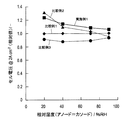
- FIG. 6 is a graph showing power generation performance evaluations at respective relative humidity of MEAs of Example 1 and Comparative Examples 1 to 3.
- FIG. FIG. 7 is a graph showing power generation performance evaluation at each relative humidity of MEAs of Examples 2 to 4 and Comparative Example 1.
- One embodiment of the present invention is a cathode gas diffusion layer comprising a polymer electrolyte membrane, and a cathode catalyst layer and a cathode fine porous layer and a cathode gas diffusion layer substrate sequentially disposed on one side of the polymer electrolyte membrane. And an anode gas diffusion layer having an anode catalyst layer, an anode fine porous layer, and an anode gas diffusion layer substrate sequentially disposed on the other side of the polymer electrolyte membrane.
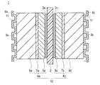
- FIG. 1 is a schematic view showing a basic configuration of a polymer electrolyte fuel cell (PEFC) 1 according to a first embodiment of the present invention.
- the PEFC 1 has a solid polymer electrolyte membrane 2 and a pair of catalyst layers (anode catalyst layer 3 a and cathode catalyst layer 3 c) sandwiching the solid polymer electrolyte membrane 2.
- the laminate of the solid polymer electrolyte membrane 2 and the catalyst layers (3a, 3c) is further sandwiched by a pair of gas diffusion layers (GDL) (anode gas diffusion layer 4a and cathode gas diffusion layer 4c).
- GDL gas diffusion layers
- the solid polymer electrolyte membrane 2, the pair of catalyst layers (3a, 3c), and the pair of gas diffusion layers (4a, 4c) constitute a membrane electrode assembly (MEA) 10 in a stacked state.
- MEA membrane electrode assembly
- the anode gas diffusion layer 4a has an anode fine porous layer 5a and an anode gas diffusion layer base 6a.
- the anode fine porous layer 5a is disposed in contact with the anode catalyst layer 3a.
- the cathode microporous layer 5c has the cathode microporous layer 5c and the cathode gas diffusion layer substrate 6c.
- the cathode microporous layer 5c is disposed in contact with the cathode catalyst layer 3c.
- the MEA 10 is further sandwiched by a pair of separators (anode separator 8a and cathode separator 8c).
- separators (8a, 8c) are illustrated as being located at both ends of the illustrated MEA 10.
- the separator is generally used also as a separator for an adjacent PEFC (not shown).
- MEAs constitute a stack by being sequentially stacked via the separators.
- a gas seal portion is disposed between the separators (8a, 8c) and the solid polymer electrolyte membrane 2 or between the PEFC 1 and another PEFC adjacent thereto.
- the separators (8a, 8c) can be obtained, for example, by pressing a thin plate having a thickness of 0.5 mm or less to form a concavo-convex shape as shown in FIG.
- the protrusions viewed from the MEA side of the separators (8a, 8c) are in contact with the MEA 10. Thereby, the electrical connection with MEA 10 is secured.
- the recesses (spaces between the separator and the MEA generated due to the uneven shape of the separator) as viewed from the MEA side of the separator (8a, 8c) are gases for circulating gas during operation of the PEFC 1 It functions as a flow path.
- a fuel gas for example, hydrogen or the like
- an oxidant gas for example, air or the like
- the recess seen from the side opposite to the MEA side of the separators (8a, 8c) is taken as the refrigerant flow path 11 for circulating the refrigerant (for example, water) for cooling the PEFC during operation of the PEFC 1.
- the separator is usually provided with a manifold (not shown). The manifold functions as a connecting means for connecting the cells when configuring the stack. With such a configuration, mechanical strength of the fuel cell stack can be secured.
- the separators (8a, 8c) are formed in a concavo-convex shape.
- the separator is not limited to only such a concavo-convex form, and may be any form such as a flat or a concavo-convex form as long as the functions of the gas flow path and the refrigerant flow path can be exhibited. It is also good.
- the anode gas diffusion layer 4a of the present invention may further include an anode intermediate layer (MPL) 7a between the anode fine porous layer 5a and the anode gas diffusion layer substrate 6a.
- MPL anode intermediate layer
- the cathode microporous layer 5c further includes a cathode intermediate layer (MPL) 7c between the cathode microporous layer 5c and the cathode gas diffusion layer substrate 6c.
- MPL cathode intermediate layer
- FIG. 2 is a schematic view showing a basic constitution intermediate layer (MPL) of a polymer electrolyte fuel cell (PEFC) 1 according to a second embodiment of the present invention.
- the anode gas diffusion layer 4a and the cathode gas diffusion layer 4c according to the present embodiment have the anode intermediate layer (MPL) 7a and the cathode intermediate layer (MPL) 7c, respectively, except for the anode gas diffusion layer 4a of the first embodiment. And the cathode gas diffusion layer 4c, respectively.
- an intermediate layer (MPL) 7a is not disposed and an embodiment in which the cathode intermediate layer (MPL) 7c is not disposed are also included in the present invention.
- anode and the cathode when the same member can be applied to the anode and the cathode, they are collectively described without the designation of the anode and the cathode.
- the anode catalyst layer and the cathode catalyst layer are collectively described as a "catalyst layer".
- the anode and the cathode do not have to be the same member but may be different.
- the anode gas diffusion layer 4a has the anode fine porous layer 5a and the anode gas diffusion layer base 6a, and if necessary, the anode fine porous layer 5a and the anode gas diffusion layer base 6a Further includes an anode intermediate layer (MPL) 7a.
- MPL anode intermediate layer
- the relative gas diffusion coefficient of the anode fine porous layer 5a is smaller than the relative gas diffusion coefficient of the cathode fine porous layer 5c by 0.05 [ ⁇ ] or more.
- the upper limit of the difference is not particularly limited.
- the method of controlling the difference between the relative gas diffusion coefficients of the fine porous layers on the anode and cathode sides as described above is not particularly limited. Preferably, this can be achieved by using a flat conductive material for the cathode microporous layer 5c and a particulate conductive material for the cathode microporous layer 5c, respectively, as described in detail below.
- the “relative gas diffusion coefficient of the microporous layer” on the anode and cathode sides is measured by the following method.
- the “relative gas diffusion coefficient” is a value obtained by dividing the gas diffusion coefficient D eff in the fine porous layer by the gas diffusion coefficient D bulk in the atmosphere, as shown in the following equation 1.
- D re is a relative gas diffusion coefficient [ ⁇ ]
- D eff is an effective gas diffusion coefficient [m 2 / s]
- D bulk is a gas diffusion coefficient in bulk [m 2 / s]
- ⁇ is the porosity [ ⁇ ]
- ⁇ is the degree of tortuosity [ ⁇ ].
- the relative gas diffusion coefficient of the anode fine porous layer 5a is not particularly limited as long as it is smaller than the relative gas diffusion coefficient of the cathode fine porous layer 5c by 0.05 [-] or more as described above.
- the relative gas diffusion coefficient of the anode microporous layer 5a is preferably 0.05 to 0.2 [-], 0.1 to 0.2 It is more preferable that it is-]. Within such a range, water / steam can be more effectively suppressed / prevented from permeating the anode fine porous layer on the anode side.
- the amount of water sufficient to suppress and prevent the water from being discharged through the GDL and separator is sufficient to maintain proton conductivity. And can be secured in the catalyst layer. Therefore, it is possible to suppress or prevent the deterioration of the power generation performance by suppressing the dryout which is a problem in the dry condition.
- the generated water is sufficiently discharged through the GDL and the separator. Therefore, even under wet conditions, water from the inside of the MEA can be discharged (without deteriorating cathode flooding) to improve flooding resistance. Therefore, the MEA of the present invention is more compatible with both dryout resistance and flooding resistance.
- the method of controlling the relative gas diffusion coefficient of the anode fine porous layer 5a as described above is not particularly limited. Preferably, this can be achieved by using a flat conductive material for the anode microporous layer 5a, as described in detail below.
- the thickness of the anode fine porous layer 5a is not limited as long as the dry out resistance (water vapor diffusion resistance) can be exhibited.
- the thickness of the anode microporous layer 5a is 10 to 100 ⁇ m, more preferably 20 to 90 ⁇ m, and still more preferably 20 to 80 ⁇ m. With such a thickness, the anode microporous layer 5a can exhibit sufficient dry-out resistance (water vapor diffusion resistance).
- the bending degree of the anode fine porous layer 5a is not limited as long as it can suppress and prevent plastic deformation.
- the bending degree of the anode microporous layer 5a is 2.5 to 10, and more preferably 3 to 6. With such a degree of curvature, the transport resistance of water vapor in the anode fine porous layer can be effectively improved. Therefore, under dry conditions, dryout of the polymer electrolyte membrane and the anode catalyst layer can be effectively suppressed / prevented.
- the degree of curvature ( ⁇ ) of the fine porous layer can be determined by porosity ( ⁇ ) / relative gas diffusion coefficient (D re ) as shown in the above-mentioned formula 1. Also, “porosity ( ⁇ )” can be measured by mercury porosimetry.
- the porosity of the anode fine porous layer 5a is not limited as long as the dry out resistance (water vapor diffusion resistance) can be exhibited.
- the porosity of the anode microporous layer 5a is 40 to 80%, and more preferably 50 to 75%. With such a porosity, the anode microporous layer 5a can exhibit sufficient dry-out resistance (water vapor diffusion resistance).
- the "porosity of the microporous layer" can be measured by mercury porosimetry.
- the water vapor effective diffusion coefficient (300 K) of the anode fine porous layer 5a is not limited as long as the dry out resistance (water vapor diffusion resistance) can be exhibited.
- the water vapor effective diffusion coefficient (300 K) of the anode microporous layer 5a is 1.5 ⁇ 10 -6 to 6.0 ⁇ 10 -6 [m 2 / s], and 3.0 ⁇ 10 -6 It is more preferable that the ratio is about 5.0 ⁇ 10 ⁇ 6 [m 2 / s]. With such a water vapor effective diffusion coefficient (300 K), the anode fine porous layer 5a can effectively improve the transport resistance of water vapor in the anode fine porous layer.
- the water vapor effective diffusion coefficient (300 K) of the microporous layer is measured by the following method.
- the gas diffusion coefficient is measured as follows using the oxygen diffusion coefficient measurement device described in JP-A-2007-278826 (particularly, paragraphs “0027” to “0031”). That is, after the anode gas diffusion layer (porous body P) is impregnated with a sufficient amount of water, it is held in the porous body holder of the oxygen sensor. Next, the oxygen sensor holding the anode gas diffusion layer is placed on an electronic balance and weighed. And the oxygen sensor of the state mounted in this electronic balance is accommodated in the airtight container which can adjust internal temperature and humidity. In addition, an arithmetic unit for calculating the oxygen diffusion coefficient of the anode gas diffusion layer is installed outside the sealed container, and the result measured by the electronic balance is output to the arithmetic unit. There is.
- the change over time of the weight of water contained in the anode gas diffusion layer held by the porous body holder is measured by an electronic balance, and the measurement result is output to the arithmetic device.
- a receiver is connected to this arithmetic device.
- the signal transmitted from the transmitter connected to the oxygen sensor is received by the receiver and input to the computing device.
- the oxygen sensor outputs a current proportional to the amount of oxygen transmitted through the anode gas diffusion layer.
- the output from the oxygen sensor is transmitted and received by the transmitter and the receiver and output to the computing device. Then, in the arithmetic unit, the amount of oxygen transmitted through the anode gas diffusion layer can be obtained based on the output from the oxygen sensor, and the oxygen diffusion coefficient of the anode gas diffusion layer can be calculated from the amount of oxygen.
- the relative gas diffusion coefficient (D re ) is calculated using the oxygen diffusion coefficient obtained here. Also, the value obtained by multiplying the relative gas diffusion coefficient (D re ) obtained here by the water vapor diffusion coefficient (D bulk ) 2.57 ⁇ 10 ⁇ 5 [m 2 / s] (@ 300 K) in bulk is It becomes the water vapor effective diffusion coefficient (300 K).
- the anode fine porous layer 5a may be formed of any material as long as it can exhibit dryout resistance (water vapor diffusion resistance), but preferably contains a flat conductive material. Thereby, the flexibility of the anode microporous layer and the water vapor transport resistance can be improved.
- the form in the case where the anode microporous layer 5a contains a flat conductive material is not particularly limited, and for example, the form shown in FIG. 3 can be mentioned.
- FIG. 3 is a schematic cross-sectional view showing a basic configuration of an anode microporous layer according to a preferred embodiment of the present invention.
- the anode microporous layer 5a is comprised of a flat conductive material 21 and, if necessary, a binder (not shown).
- the flat conductive material 21 is oriented substantially in parallel along the surface direction of the anode fine porous layer 5a, and the diffusion of water vapor in the thickness / surface direction of the anode fine porous layer 5a Control and prevent discharge, and ensure surface conductivity.
- the water vapor can be suppressed or prevented from being discharged from the anode side, and the water retention of the solid polymer electrolyte membrane and the catalyst layer sufficient to maintain the proton conductivity can be maintained. Therefore, it is possible to suppress or prevent the deterioration of the power generation performance by suppressing the dryout which is a problem in the dry condition.
- the anode microporous layer 5a is comprised of a flat conductive material 21, a particulate conductive material 22 and, if necessary, a binder (not shown).
- the flat conductive material 21 is oriented substantially in parallel along the surface direction of the anode fine porous layer 5a, and the diffusion of water vapor in the thickness / surface direction of the anode fine porous layer 5a Control and prevent discharge, and ensure surface conductivity. This suppresses or prevents water vapor from being discharged from the anode side, and can maintain the water retentivity of the solid polymer electrolyte membrane and the catalyst layer sufficient to maintain the proton conductivity.
- the granular conductive material 22 intervenes between the flat conductive materials 21 as a conductive pass material.
- the resistance in the thickness direction of the anode fine porous layer 5a can be reduced to improve the conductivity.
- the particulate conductive material 22 can also function as a spacer material to improve gas permeability in the thickness and in the surface direction. Therefore, the gas (fuel gas) can be favorably transmitted from the separator side. Therefore, while suppressing the dryout which becomes a problem in dry conditions, while suppressing and preventing the fall of electric power generation performance, electroconductivity can be improved.
- the anode microporous layer 5a is composed of flat conductive materials 21, 21 'of different sizes and, if necessary, a binder (not shown).
- the flat conductive material 21 and 21 ' are oriented substantially in parallel along the surface direction of the anode fine porous layer 5a, and the water vapor in the thickness / plane direction of the anode fine porous layer 5a Control and prevent the diffusion and discharge of water, and ensure the conductivity in the surface direction. This suppresses or prevents water vapor from being discharged from the anode side, and can maintain the water retentivity of the solid polymer electrolyte membrane and the catalyst layer sufficient to maintain the proton conductivity.
- a flat conductive material 21 ′ having a small size is interposed between the flat conductive materials 21 as a conductive pass material.
- the resistance in the thickness direction of the anode fine porous layer 5a can be reduced to improve the conductivity.
- the flat conductive material 21 'having a small size can also function as a spacer material to improve the gas permeability in the thickness direction and the surface direction. Therefore, gas (fuel gas and oxidant gas) can be favorably permeated from the separator side. Therefore, while suppressing the dryout which becomes a problem in dry conditions, while suppressing and preventing the fall of electric power generation performance, electroconductivity can be improved.
- the anode microporous layer 5a is comprised of a flat conductive material 21, granular conductive materials 22, 22 'of different sizes, and, if necessary, a binder (not shown) Ru.
- the flat conductive material 21 is oriented substantially in parallel along the surface direction of the anode fine porous layer 5a, and the diffusion of water vapor in the thickness / surface direction of the anode fine porous layer 5a Control and prevent discharge, and ensure surface conductivity. This suppresses or prevents water vapor from being discharged from the anode side, and can maintain the water retentivity of the solid polymer electrolyte membrane and the catalyst layer sufficient to maintain the proton conductivity.
- granular conductive materials 22 and 22 ' are interposed between the flat conductive materials 21 as conductive pass materials. Thereby, the resistance in the thickness direction of the anode fine porous layer 5a can be reduced to improve the conductivity.
- the large-sized granular conductive material 22 ' can also function as a spacer material to improve the gas permeability in the thickness direction and the surface direction. Therefore, the gas (fuel gas) can be favorably transmitted from the separator side. Thereby, even under low humidity conditions, the solid polymer electrolyte membrane and the catalyst layer can secure a sufficient amount of water. Therefore, while suppressing the dryout which becomes a problem in dry conditions, while suppressing and preventing the fall of electric power generation performance, electroconductivity can be improved.
- the anode microporous layer 5a is formed of flat conductive materials 21 and 21 'having different sizes, granular conductive materials 22' having a large size, and a binder (not shown). It consists of.
- the flat conductive material 21 and 21 ' are oriented substantially in parallel along the surface direction of the anode fine porous layer 5a, and the water vapor in the thickness / plane direction of the anode fine porous layer 5a Control and prevent the diffusion and discharge of water, and ensure the conductivity in the surface direction.
- the small-sized flat conductive material 21 'and the small-sized granular conductive material 22 can also function as a spacer material for improving the gas permeability in the thickness and the surface direction.
- the gas (fuel gas) can be favorably transmitted from the separator side.
- the solid polymer electrolyte membrane and the catalyst layer can secure a sufficient amount of water. Therefore, while suppressing the dryout which becomes a problem in dry conditions, while suppressing and preventing the fall of electric power generation performance, electroconductivity can be improved.
- the structure of the anode fine porous layer (a combination example of the flat conductive material and the granular conductive material) shown in FIG. 3 is only a representative example, and is not limited thereto.
- the anode microporous layer shown in FIG. 3B may be combined with a flat conductive material 21 'having a smaller size, or may be added with a granular conductive material 22' having a larger size.
- FIGS. 3B to 3E are preferable in consideration of dryout resistance (water vapor diffusion resistance), conductivity and the like.
- the flat conductive material contributes to the improvement of the dryout resistance (water vapor diffusion resistance) in the thickness direction and the surface direction of the anode fine porous layer and the reduction of the resistance in the surface direction (conductivity improvement).
- the size of the flat conductive material is not particularly limited as long as the diffusion / discharge of water vapor in the thickness / surface direction of the anode fine porous layer 5 a can be suppressed / prevented.
- the thickness of the flat conductive material is preferably 0.05 to 1 ⁇ m, and more preferably 0.05 to 0.3 ⁇ m.
- the aspect ratio of the flat conductive material is preferably more than 3, more preferably 10 to 1000, and particularly preferably 10 to 1000.
- the anode fine porous layer preferably contains a flat conductive material having a thickness of 0.05 to 1 ⁇ m and an aspect ratio of 10 to 1000. If it is a flat conductive material having such a shape, the flat conductive material is oriented and arranged along the surface direction of the anode fine porous layer to diffuse / discharge water vapor in the thickness / surface direction. It can be suppressed / prevented and transport resistance can be improved. Therefore, under dry conditions, dryout of the polymer electrolyte membrane and the anode catalyst layer can be effectively suppressed / prevented. At the same time, the conductivity in the surface direction of the anode microporous layer can be secured, and the flexibility of the anode microporous layer can be improved.
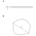
- the thickness of the flat conductive material is the thickness when the flat conductive material is viewed from the side, as shown in FIG. 4A. (“H ( ⁇ m)” in the figure). In the case where the thickness of the flat conductive material is not constant, the maximum thickness is intended.
- the flat diameter of the flat conductive material is, as shown in FIG. 4B, the flat diameter (“D ( ⁇ m in the figure) when the flat conductive material (scale-like graphite) is viewed from directly above “)), And where the flat diameter of the flat conductive material (flaky graphite) is not constant, the maximum flat diameter is intended.
- the flat diameter of the flat conductive material can be measured by a known method, but in the present specification, it means a value measured by a laser diffraction / scattering method.
- the flat diameter of the flat conductive material is not particularly limited, but is preferably 5 to 50 ⁇ m. With such a size, the dryout resistance (water vapor diffusion resistance) in the thickness direction and in the surface direction of the anode microporous layer can be improved without affecting the thickness of the anode microporous layer. In addition, the resistance in the surface direction can be reduced (the conductivity can be improved).
- the aspect ratio of the flat conductive material is the flat diameter (D) of the flat conductive material determined above with respect to the thickness (H) of the flat conductive material determined above. Is defined as the ratio (D / H) of
- a flat conductive material 21 having a large size and a flat having a small size are used.
- the size of the conductive material 21 ' is not particularly limited, and preferably has the thickness and aspect ratio as described above. According to a preferred embodiment, the thickness and aspect ratio of the large sized flat conductive material 21 are the same as described for the flat conductive material above.
- the thickness of the small-sized flat conductive material 21 ' is preferably 0.05 to 1 ⁇ m, and more preferably 0.05 to 0.5 ⁇ m.
- the aspect ratio of the small-sized flat conductive material 21 ′ is preferably 1 to 100, and more preferably 1 to 20.
- the flat diameter of the small-sized flat conductive material 21 ' is not particularly limited, but is preferably 0.01 to 30 ⁇ m. With such a shape, the effects described in FIGS. 3C and 3E can be more effectively exhibited.
- the flat conductive material is not particularly limited as long as the diffusion / discharge of water vapor in the thickness / surface direction of the anode fine porous layer 5a can be suppressed / prevented.
- scale-like graphite is preferable. Flaky graphite has high crystallinity and has a large scale-like shape with an aspect ratio (planar diameter D / thickness H). With such scaly graphite, the flat conductive material can be oriented and disposed along the surface direction of the anode fine porous layer to suppress / prevent the diffusion / discharge of water vapor in the thickness / surface direction. .
- the conductivity in the surface direction of the anode microporous layer can be secured, and the flexibility of the anode microporous layer can be improved.
- scale-like graphite is inexpensive, has high conductivity, and can effectively improve power generation performance. That is, the flat conductive material is particularly preferably scale-like graphite having a thickness of 0.05 to 1 ⁇ m and an aspect ratio of 10 to 1000.
- the specific surface area (BET specific surface area) of scale-like graphite when the flat conductive material is scale-like graphite is not particularly limited, but is preferably 2000 m 2 / g or less, more preferably 15 to 1000 m 2 / g It is.
- the dryout resistance (water vapor diffusion resistance) of thickness / plane direction of the anode fine porous layer 5a can be further improved. .
- the blending amount of the flat conductive material is not particularly limited as long as it can achieve appropriate dry-out resistance (water vapor diffusion resistance) and conductivity.
- the blending amount (solid content) of the flat conductive material is preferably 10 to 95% by weight, and 15 to 85% by weight with respect to all the components constituting the anode fine porous layer. Some are more preferable, and 40 to 70% by weight is even more preferable.
- the compounding quantity of the said flat-shaped electroconductive material is the total compounding quantity of these flat-shaped electroconductive materials, when using flat-shaped electroconductive materials 21 and 21 'of which sizes differ as a flat-shaped electroconductive material I assume.
- a sufficient amount of the flat conductive material can be disposed along the surface direction of the anode fine porous layer to suppress / prevent the diffusion / discharge of water vapor in the thickness / surface direction.
- the conductivity in the surface direction of the anode fine porous layer can be secured, and the flexibility of the anode fine porous layer can be improved.
- the anode microporous layer 5a may include a particulate conductive material in addition to the flat conductive material.
- the particulate conductive material is not particularly limited, but, for example, carbon black such as oil furnace black, acetylene black, ketjen black, thermal black, channel black, lamp black, small scale flake graphite, carbon fiber, etc. Can be mentioned.
- the particulate conductive material may be prepared by itself or a commercially available conductive material (carbon material) may be used. Commercially available conductive materials (carbon materials) include Vulcan (registered trademark), ketjen black (registered trademark), black pearl (registered trademark) and the like.
- carbon black may be subjected to graphitization treatment.
- the particulate conductive material may be used alone or in the form of a mixture of two or more.
- carbon black is preferable for the large-size granular conductive material 22 in the case of using granular conductive materials 22 and 22 'having different sizes, and acetylene black and ketjen are preferable. Black is more preferred.
- the size of the particulate conductive material is also not particularly limited.
- large-size granular conductive materials 22 have an average particle size (average primary particle size, diameter). Is preferably 10 nm or more and less than 5 ⁇ m, and more preferably 0.05 to 20 ⁇ m.
- the size of the small-sized granular conductive material 22 ' is preferably 1 to 10 nm, more preferably 0.05 to 5 nm, as the average particle diameter.
- the size of the particulate conductive material can be measured by a known method, but in the present specification, unless otherwise specified, an observation means such as a scanning electron microscope (SEM) or a transmission electron microscope (TEM) A value calculated as an average value of particle diameters of particles observed in several to several tens of visual fields is used. Also, “particle size” means the largest distance among the distance between any two points on the contour line of the particle. In the present specification, the “particulate conductive material” refers to one having an aspect ratio (planar diameter D / thickness H) of about 1 to 3.
- the specific surface area (BET specific surface area) of carbon black when the particulate conductive material is carbon black is not particularly limited, but is preferably 2000 m 2 / g or more, and more preferably 15 to 1000 m 2 / g.
- the resistance in the thickness direction of the anode fine porous layer 5a can be reduced to further improve the conductivity.
- the compounding amount of the particulate conductive material is not particularly limited as long as it can achieve appropriate gas permeability improvement and conductivity improvement.
- the blending amount (solid content) of the small-sized granular conductive material is preferably 1 to 35% by weight with respect to all the components constituting the anode microporous layer.
- the compounding quantity of the said granular conductive material is made into the total compounding quantity of these granular conductive materials, when flat-shaped conductive material 22 and 22 'from which a magnitude
- the particulate conductive material blended in such an amount is interposed between the flat conductive materials as a conductive pass material to reduce the resistance in the thickness direction of the anode fine porous layer to improve the conductivity.
- Can. Moreover, it functions as a spacer material that improves the gas permeability in the thickness and plane direction, and can achieve good gas permeability.
- the blending amount of acetylene black is more preferably 5 to 40% by weight with respect to all components constituting the anode fine porous layer. With such an amount, sufficient contact points and contact area can be obtained to improve conductivity.
- the blending amount of ketjen black is preferably 1 to 20% by weight with respect to all the components constituting the anode fine porous layer, and 3 It is more preferably ⁇ 15 wt% and even more preferably 3-5 wt%. With such an amount, sufficient contact points and contact area can be obtained to improve conductivity. Moreover, it functions also as a spacer material which improves the gas permeability of thickness and a surface direction, and can achieve favorable gas permeability.
- the binder that can be used if necessary is not particularly limited, and a known binder can be used.
- it has a function of securing the strength of the anode microporous layer by bonding conductive materials such as flat conductive material and granular conductive material to each other, and also has a function as a water repellent.
- a binder PTFE (polytetrafluoroethylene), tetrafluoroethylene-hexafluoropropylene copolymer (FEP), tetrafluoroethylene-perfluoroalkyl vinyl ether copolymer (PFA) and the like can be mentioned.
- the amount of binder is not particularly limited as long as it exerts the above-mentioned effects, but it is 5 to 40% by weight with respect to all the components constituting the anode fine porous layer. Is preferred. With such an amount, the conductive materials can be bound to each other to ensure sufficient strength of the anode fine porous layer and to exhibit appropriate water repellency.
- the anode fine porous layer 5a is disposed on the anode gas diffusion layer substrate 6a (or the anode intermediate layer (MPL) 7a disposed on the anode gas diffusion layer substrate 6a).
- the MEA of the present invention can achieve both dryout resistance and flooding resistance, and can effectively exhibit dryout resistance (water vapor diffusion resistance) on the anode side.
- the dry out resistance (water vapor diffusion resistance) of the anode gas diffusion layer is not particularly limited as long as the dry out resistance can be sufficiently exhibited, but the water vapor effective diffusion coefficient (300 K) is 2 ⁇ 10 ⁇ 6 to is preferably 6.0 ⁇ 10 -6 [m 2 / s], and more preferably 3.0 ⁇ 10 -6 ⁇ 6.0 ⁇ 10 -6 [m 2 / s].
- the anode gas diffusion layer having the gas diffusion coefficient as described above is excellent in dryout resistance (water vapor diffusion resistance) on the anode side.
- the method of forming the anode microporous layer is not particularly limited.
- a preferred embodiment of the method for forming an anode microporous layer according to the present invention will be described, but the present invention is not limited to the following embodiment.
- an ink containing a flat conductive material, and optionally, a granular conductive material, a binder, a surfactant, and a thickener is prepared.
- the ink is stirred and defoamed, then applied on a heat resistant holding sheet, dried and fired to form an anode fine porous layer on the heat resistant holding sheet.
- a heat resistant holding sheet a polyester sheet such as a PTFE (polytetrafluoroethylene) sheet or a PET (polyethylene terephthalate) sheet, a polyimide sheet, a polypropylene sheet, a polyethylene sheet, a polysulfone sheet, a polytetrafluoroethylene sheet, etc.
- a polyester sheet such as a PTFE (polytetrafluoroethylene) sheet or a PET (polyethylene terephthalate) sheet, a polyimide sheet, a polypropylene sheet, a polyethylene sheet, a polysulfone sheet, a
- a polyimide sheet can be used suitably.
- the thickness of the heat resistant holding sheet is not particularly limited, but is preferably about 10 to 100 ⁇ m.
- a gas diffusion layer substrate or a gas diffusion layer substrate (GDL with MPL) in which an intermediate layer is previously formed may be used.
- the drying conditions are not particularly limited, but for example, conditions of 80 to 120 ° C. for 1 to 60 minutes are preferable.
- the firing conditions are also not particularly limited, but for example, the conditions of 120 to 350 ° C. for 5 to 60 minutes are preferable.
- the anode fine porous layer is peeled off from the heat resistant holding sheet, and the anode gas is laminated on the gas diffusion layer base on which the gas diffusion layer base or the intermediate layer is previously formed by, for example, hot pressing.
- a diffusion layer can be obtained.
- the ink is directly coated with the gas diffusion layer base material or intermediate layer It may be applied to the middle layer side of the formed gas diffusion layer substrate, dried and fired to form an anode fine porous layer on the heat resistant holding sheet to obtain an anode gas diffusion layer.
- the drying and firing conditions are not particularly limited, but the same conditions as described above are preferably applied.
- the cathode microporous layer 5c has the cathode microporous layer 5c and the cathode gas diffusion layer base 6c, and if necessary, the cathode microporous layer 5c and the cathode gas diffusion layer base 6c. And a cathode intermediate layer (MPL) 7c.
- the relative gas diffusion coefficient of the cathode fine porous layer 5c is not particularly limited as long as it is larger than the relative gas diffusion coefficient of the anode fine porous layer 5a by 0.05 [-] or more as described above.
- the relative gas diffusion coefficient of the cathode microporous layer 5c is preferably 0.1 to 0.8 [-], more preferably 0.2 to 0.5 [-]. preferable.
- the water generated at the cathode passes through the cathode fine porous layer 5 c well and is discharged through the GDL and the separator. Therefore, even under wet conditions, water from within the MEA can be discharged (without deteriorating cathode flooding) to improve flooding resistance.
- the anode fine porous layer 5a more effectively suppresses and prevents water / steam from permeating the anode fine porous layer. For this reason, even under dry (low humidity) conditions, the amount of water sufficient to suppress and prevent the water from being discharged through the GDL and separator is sufficient to maintain proton conductivity. And can be secured in the catalyst layer. Therefore, it is possible to suppress or prevent the deterioration of the power generation performance by suppressing the dryout which is a problem in the dry condition. Therefore, the MEA of the present invention is more compatible with both dryout resistance and flooding resistance.
- the method of controlling the relative gas diffusion coefficient of the cathode fine porous layer 5c as described above is not particularly limited. Preferably, this can be achieved by using a particulate conductive material for the cathode microporous layer 5c, as described in detail below.
- the thickness of the cathode fine porous layer 5c is not limited as long as the water generated at the cathode can be efficiently discharged and flooding resistance can be exhibited.
- the thickness of the cathode microporous layer 5c is 10 to 100 ⁇ m, and more preferably 20 to 80 ⁇ m. With such a thickness, water generated at the cathode is discharged through the GDL on the cathode side and the separator. Therefore, even under wet conditions, water from within the MEA can be discharged (without deteriorating cathode flooding) to improve flooding resistance.
- the bending degree of the cathode fine porous layer 5c is not limited as long as it can suppress and prevent plastic deformation.
- the tonicity of the cathode microporous layer 5c is 1 to 15, more preferably 1.5 to 10, still more preferably 1.8 to 8, and 3 to 6. Is even more preferred. With such a degree of inflection, it is possible to relieve the bending stress to the compressive force in the surface direction at the time of stack assembly, and to suppress or prevent the plastic deformation of the cathode fine porous layer.
- the porosity of the cathode fine porous layer 5c is not limited as long as it can exhibit flooding resistance.
- the porosity of the cathode microporous layer 5c is 40 to 80%, more preferably 50 to 75%. With such a porosity, water generated at the cathode is efficiently discharged through the GDL on the cathode side and the separator. Therefore, even under wet conditions, water from the inside of the MEA can be discharged (without deteriorating cathode flooding) to further improve the flooding resistance.
- the water vapor effective diffusion coefficient (300 K) of the cathode fine porous layer 5c is not limited as long as it can exhibit flooding resistance.
- the water vapor effective diffusion coefficient (300 K) of the cathode microporous layer 5 c is 1.5 ⁇ 10 ⁇ 6 to 6.0 ⁇ 10 ⁇ 5 [m 2 / s], and is 5.0 ⁇ 10 ⁇ 6. It is more preferably about 5.0 ⁇ 10 ⁇ 5 [m 2 / s], and still more preferably 1.0 ⁇ 10 ⁇ 5 to 3.0 ⁇ 10 ⁇ 5 [m 2 / s].
- the cathode fine porous layer 5c may be formed of any material as long as it can exhibit flooding resistance, but preferably contains a particulate conductive material, more preferably carbon particles.
- a particulate conductive material more preferably carbon particles.
- the water generated at the cathode can pass through the gaps between the particles and be discharged out of the system.
- the carbon particles are not particularly limited, and conventionally known materials such as carbon black, graphite (including granular graphite), expanded graphite and the like may be appropriately adopted.
- carbon black such as oil furnace black, channel black, lamp black, thermal black and acetylene black can be preferably used because of excellent electron conductivity and large specific surface area.
- Such carbon particles may be commercially available products, and may be Cabot Vulcan XC-72, Vulcan P, Black Pearls 880, Black Pearls 1100, Black Pearls 1300, Black Pearls 2000, Regal 400, Lion Ketjen Black EC, oil furnace black such as Mitsubishi Chemical's # 3150, # 3250; acetylene black such as Denka Black manufactured by Denki Kagaku Kogyo Co., Ltd.
- artificial graphite or carbon obtained from organic compounds such as natural graphite, pitch, coke, polyacrylonitrile, phenol resin, furan resin, etc.
- processing such as graphitization may be performed on the carbon particles.
- the above materials may be used alone or in the form of a mixture of two or more.
- the particle diameter of the carbon particles is not limited as long as it can exhibit the flooding resistance.
- the average particle size (average primary particle size, diameter) of the carbon particles is 10 nm or more and less than 5 ⁇ m, and more preferably 10 to 500 nm.
- the size of the carbon particles can be measured by a known method, but in the present specification, unless otherwise stated, the definition is the same as the average particle size of the above-mentioned particulate conductive material.
- the specific surface area (BET specific surface area) of the carbon particles is not particularly limited, but is preferably 10 to 2000 m 2 / g or more, and more preferably 20 to 1000 m 2 / g.
- the compounding amount of the carbon particles is not particularly limited as long as appropriate gas permeability improvement and conductivity improvement can be achieved.
- the content of carbon particles (solid content) is preferably 40 to 90% by weight, and more preferably 50 to 85% by weight, with respect to all the components constituting the cathode fine porous layer. More preferable.
- the carbon particles compounded in such an amount impart conductivity to the cathode fine porous layer sufficient as a conductive path material, reduce the resistance in the thickness direction of the cathode fine porous layer, and improve the conductivity. be able to.
- water / steam and oxidant gas pass well between the carbon particles to improve the gas permeability in the thickness and plane direction and achieve good gas permeability.
- the blending amount of acetylene black is more preferably 50 to 85% by weight with respect to all the components constituting the cathode fine porous layer. With such an amount, sufficient contact points and contact area can be obtained to improve conductivity.
- the water / steam and the oxidant gas can be favorably passed between the carbon particles to improve the gas permeability in the thickness direction and the surface direction, thereby achieving the good gas permeability.
- the blending amount of ketjen black is more preferably 50 to 85% by weight with respect to all the components constituting the cathode fine porous layer.
- the water / steam and the oxidant gas can be favorably passed between the carbon particles to improve the gas permeability in the thickness direction and the surface direction, thereby achieving the good gas permeability.
- the binder that can be used if necessary is not particularly limited, and a known binder can be used.
- a known binder can be used.
- the same ones as exemplified in the above-mentioned cathode microporous layer can be used.
- the amount of binder (solid content) is not particularly limited as long as it exerts the above-mentioned effects, but it is 10 to 60% by weight based on all components constituting the cathode fine porous layer. Is preferred. With such an amount, the conductive materials can be bound to each other to ensure sufficient strength of the cathode fine porous layer and to exhibit appropriate water repellency.
- the cathode microporous layer 5c is disposed on the cathode gas diffusion layer substrate 6c (or the cathode intermediate layer (MPL) 7c disposed on the cathode gas diffusion layer substrate 6c).
- the MEA of the present invention can achieve both the dryout resistance and the flooding resistance, and can effectively exhibit the flooding resistance on the cathode side.
- the flooding resistance of the cathode gas diffusion layer is not particularly limited as long as water generated at the cathode can be sufficiently discharged, but the water vapor effective diffusion coefficient (300 K) is 1.5 ⁇ 10 ⁇ 6 to 6.0.
- the cathode gas diffusion layer having the gas diffusion coefficient as described above is excellent in the flooding resistance at the cathode.
- the method of forming the cathode microporous layer is not particularly limited.
- a preferred embodiment of the method for forming a cathode microporous layer according to the present invention will be described, but the present invention is not limited to the following embodiment.
- an ink containing carbon particles, a binder, a surfactant, and a thickener is prepared.
- the ink is stirred and defoamed, then applied on a heat resistant holding sheet, dried and fired to form a cathode fine porous layer on the heat resistant holding sheet.
- the heat resistant holding sheet is not particularly limited, and is the same as the example of the method of forming the anode fine porous layer.
- the thickness of the heat resistant holding sheet is not particularly limited, but is preferably about 10 to 100 ⁇ m.
- a gas diffusion layer substrate or a gas diffusion layer substrate (GDL with MPL) in which an intermediate layer is previously formed may be used.
- the drying conditions are not particularly limited, but for example, the conditions of 60 to 150 ° C. for 1 to 60 minutes are preferable.
- the firing conditions are also not particularly limited, but for example, the conditions of 120 to 350 ° C. for 5 to 60 minutes are preferable.
- the cathode microporous layer is peeled off from the heat resistant holding sheet, and the cathode gas is laminated, for example, on a gas diffusion layer substrate on which a gas diffusion layer substrate or an intermediate layer is previously formed by hot pressing or the like.
- a diffusion layer can be obtained.
- the ink is directly coated with the gas diffusion layer base material or intermediate layer It may be applied to the intermediate layer side of the formed gas diffusion layer substrate, dried and fired to form a cathode fine porous layer on the heat resistant holding sheet to obtain a cathode gas diffusion layer.
- the drying and firing conditions are not particularly limited, but the same conditions as described above are preferably applied.
- the gas diffusion layer substrate that can be used for the anode and cathode gas diffusion layers is not particularly limited and known ones can be similarly used.
- carbon paper, carbon cloth formed of carbon fiber such as carbon cloth, paper-like paper body, felt, non-woven sheet-like material having conductivity and porosity; metal mesh, expanded metal, etching What makes a plate a base material etc.
- the thickness of the substrate is not particularly limited and may be appropriately determined in consideration of desired characteristics, but may be about 30 to 500 ⁇ m. With such a thickness, sufficient mechanical strength and permeability to gas, water and the like can be ensured.
- the gas diffusion layer base material may contain a water repellent for the purpose of enhancing the water repellency and preventing the flooding phenomenon and the like.
- the water repellent agent is not particularly limited, but fluorine-based materials such as polytetrafluoroethylene (PTFE), polyvinylidene fluoride (PVdF), polyhexafluoropropylene, tetrafluoroethylene-hexafluoropropylene copolymer (FEP), etc. Polymer materials, polypropylene, polyethylene and the like can be mentioned.
- the water repelling method is not particularly limited, and a general water repelling method may be used.
- a method of heating and drying in an oven or the like may be mentioned.
- a porous sheet of polytetrafluoroethylene (PTFE) impregnated with carbon particles may be used.
- PTFE polytetrafluoroethylene
- the manufacturing process is simplified, and handling and assembly when laminating the members of the fuel cell are facilitated.
- the water repellent treatment of the gas diffusion layer base material may not be performed, or the hydrophilic treatment may be performed.
- a combination of a gas diffusion layer substrate and a fine porous layer may be used.
- the method for forming the microporous layer on the gas diffusion layer substrate is not particularly limited.
- a slurry is prepared by dispersing carbon particles, a water repellent and the like in a solvent such as water, perfluorobenzene, dichloropentafluoropropane, alcohol solvents such as methanol, ethanol and the like.
- this slurry may be coated on a gas diffusion layer substrate and dried, or the slurry may be dried and pulverized once to form a powder, and this may be coated on the gas diffusion layer, or the like.
- heat treatment is preferably performed at about 250 to 400 ° C. using a muffle furnace or a baking furnace.
- a commercially available product in which a microporous layer is previously formed on a gas diffusion layer substrate may be used.
- the anode and / or cathode gas diffusion layer may have an intermediate layer (MPL), if necessary.
- the intermediate layer (MPL) is not particularly limited, but preferably has a large intermediate layer (MPL) gas diffusion coefficient.
- MPL intermediate layer
- gas permeability can be further improved, and power generation performance under dry conditions and wet conditions can be more effectively compatible.
- Such an intermediate layer (MPL) is not particularly limited, but may be an aggregate of carbon particles containing a water repellent if necessary.
- the carbon particles are not particularly limited, and conventionally known materials such as carbon black, graphite (including granular graphite), expanded graphite and the like may be appropriately adopted.
- carbon black such as oil furnace black, channel black, lamp black, thermal black and acetylene black can be preferably used because of excellent electron conductivity and large specific surface area.
- Such carbon particles may be commercially available products, and may be Cabot Vulcan XC-72, Vulcan P, Black Pearls 880, Black Pearls 1100, Black Pearls 1300, Black Pearls 2000, Regal 400, Lion Ketjen Black EC, oil furnace black such as Mitsubishi Chemical's # 3150, # 3250; acetylene black such as Denka Black manufactured by Denki Kagaku Kogyo Co., Ltd.
- artificial graphite or carbon obtained from organic compounds such as natural graphite, pitch, coke, polyacrylonitrile, phenol resin, furan resin, etc. may be used.
- processing such as graphitization may be performed on the carbon particles.
- the above materials may be used alone or in the form of a mixture of two or more.
- the particle size of the carbon particles is preferably about 10 to 100 nm.
- the shape of the particles of the conductive carrier is not particularly limited, and any structure such as spherical, rod-like, needle-like, plate-like, columnar, indeterminate, scaly and spindle-like can be employed.
- the particle size of the conductive carrier particles is the average secondary particle size of the conductive carrier particles.
- the measurement of the average secondary particle diameter of the conductive carrier particles can be carried out by using observation means such as a scanning electron microscope (SEM) or a transmission electron microscope (TEM) to observe particles observed in several to several tens of visual fields.
- SEM scanning electron microscope
- TEM transmission electron microscope
- the intermediate layer (MPL) preferably contains a water repellent for the purpose of further enhancing the water repellency to prevent the flooding phenomenon and the like.
- the water repellent agent is not particularly limited, but may be a fluorine-based polymer such as polytetrafluoroethylene (PTFE), polyvinylidene fluoride (PVdF), polyhexafluoropropylene, tetrafluoroethylene-hexafluoropropylene copolymer (FEP), etc.
- PTFE polytetrafluoroethylene
- PVdF polyvinylidene fluoride
- FEP tetrafluoroethylene-hexafluoropropylene copolymer
- Molecular materials, thermoplastic resins such as polyethylene and polypropylene, and the like can be mentioned.
- fluorine-based polymer materials are preferably used because they are excellent in water repellency, corrosion resistance at the time of electrode reaction, and the like.
- the mixing ratio of carbon particles to the water repellent in the intermediate layer (MPL) is preferably about 90:10 to 40:60 in weight ratio.
- the thickness of the intermediate layer (MPL) may be appropriately determined in consideration of the anode gas diffusion layer to be obtained.
- carbon particles may be bound by a binder.
- a binder that can be used here, fluorine-based polymer materials such as polytetrafluoroethylene (PTFE), polyvinylidene fluoride (PVDF), polyhexafluoropropylene, tetrafluoroethylene-hexafluoropropylene copolymer (FEP), etc.
- thermosetting resins such as phenol resin, melamine resin, and polyamide resin
- thermoplastic resins such as polypropylene and polyethylene.
- a fluorine-based polymer material is preferably used because it is excellent in water repellency, corrosion resistance at the time of electrode reaction and the like, and polytetrafluoroethylene (PTFE) is particularly preferable.
- PTFE polytetrafluoroethylene
- a binder having water repellency water repellency can be imparted to the pores (between carbon particles) in the intermediate layer (MPL), and water drainage can be improved.
- binders may be used alone or in combination of two or more.
- polymers other than these may be used.
- the content of the binder in the intermediate layer (MPL) may be appropriately adjusted so that the void structure in the intermediate layer (MPL) has desired characteristics.
- the content of the binder is preferably in the range of 5 to 60% by weight, more preferably 10 to 50% by weight, still more preferably 12 to 40% by weight based on the total weight of the intermediate layer (MPL). Preferably there. If the blend ratio of the binder is 5% by weight or more, the particles can be bonded well, and if it is 60% by weight or less, an increase in the electrical resistance of the intermediate layer (MPL) can be prevented.
- the thickness of the intermediate layer (MPL) is not particularly limited, and may be appropriately determined in consideration of the characteristics of the anode gas diffusion layer.
- the thickness of the intermediate layer (MPL) is preferably 3 to 500 ⁇ m, more preferably 5 to 300 ⁇ m, still more preferably 10 to 150 ⁇ m, and particularly preferably 20 to 100 ⁇ m. Within such a range, the balance between mechanical strength and permeability such as gas and water can be properly controlled.
- the solid polymer electrolyte membrane 2 has a function of selectively permeating protons generated in the anode catalyst layer 3a during operation of the PEFC 1 to the cathode catalyst layer 3c in the film thickness direction.
- the solid polymer electrolyte membrane 2 also has a function as a partition wall for preventing the fuel gas supplied to the anode side from being mixed with the oxidant gas supplied to the cathode side.
- the solid polymer electrolyte membrane 2 is roughly classified into a fluorine-based polymer electrolyte membrane and a hydrocarbon-based polymer electrolyte membrane depending on the type of ion exchange resin which is a constituent material.
- ion exchange resin constituting the fluorine-based polymer electrolyte membrane include Nafion (registered trademark, manufactured by DuPont), Aciplex (registered trademark, manufactured by Asahi Kasei Corporation), Flemion (registered trademark, manufactured by Asahi Glass Co., Ltd.), etc.
- Perfluorocarbon sulfonic acid based polymers perfluorocarbon phosphonic acid based polymers, trifluorostyrene sulfonic acid based polymers, ethylene tetrafluoroethylene-g-styrene sulfonic acid based polymers, ethylene-tetrafluoroethylene copolymer, polyvinylidene fluoride- Perfluorocarbon sulfonic acid polymers and the like can be mentioned.
- these fluorine-based polymer electrolyte membranes are preferably used, and particularly preferably a fluorine-based polymer electrolyte composed of a perfluorocarbon sulfonic acid-based polymer A membrane is used.
- hydrocarbon-based electrolytes include sulfonated polyethersulfone (S-PES), sulfonated polyaryletherketone, sulfonated polybenzimidazole alkyl, phosphonated polybenzimidazole alkyl, sulfonated polystyrene, sulfonated poly Etheretherketone (S-PEEK), sulfonated polyphenylene (S-PPP) and the like can be mentioned.
- S-PES sulfonated polyethersulfone
- S-PEEK sulfonated poly Etheretherketone
- S-PPP sulfonated polyphenylene
- the thickness of the solid polymer electrolyte membrane may be appropriately determined in consideration of the characteristics of the obtained fuel cell, and is not particularly limited.
- the thickness of the electrolyte layer is usually about 5 to 300 ⁇ m. When the thickness of the electrolyte layer is in such a range, the balance between the strength at the time of film formation, the durability at the time of use, and the output characteristics at the time of use can be appropriately controlled.
- the catalyst layer (anode catalyst layer 3a, cathode catalyst layer 3c) is a layer in which the cell reaction actually proceeds. Specifically, the oxidation reaction of hydrogen proceeds in the anode catalyst layer 3a, and the reduction reaction of oxygen proceeds in the cathode catalyst layer 3c.
- the catalyst layer contains a catalyst component, a conductive catalyst support (conductive support) supporting the catalyst component, and an electrolyte.
- a complex in which a catalyst component is supported on a catalyst carrier is also referred to as "electrode catalyst”.
- the catalyst component used in the anode catalyst layer is not particularly limited as long as it has a catalytic effect on the oxidation reaction of hydrogen, and known catalysts can be used in the same manner.
- the catalyst component used in the cathode catalyst layer is also not particularly limited as long as it has a catalytic effect on the reduction reaction of oxygen, and known catalysts can be used in the same manner.
- it can be selected from metals such as platinum, ruthenium, iridium, rhodium, palladium, osmium, tungsten, lead, iron, chromium, cobalt, nickel, manganese, vanadium, molybdenum, gallium, aluminum and alloys thereof .
- those containing at least platinum are preferably used in order to improve catalytic activity, poisoning resistance to carbon monoxide and the like, heat resistance and the like.
- the composition of the alloy depends on the type of metal to be alloyed, the content of platinum is preferably 30 to 90 atomic%, and the content of metal to be alloyed with platinum is preferably 10 to 70 atomic%.
- an alloy is generally a metal element to which one or more metal elements or nonmetal elements are added, and is a generic term for alloys having metallic properties.
- the structure of the alloy includes a eutectic alloy which is a so-called mixture in which component elements become separate crystals, one in which component elements completely dissolve and a solid solution, and a component element is an intermetallic compound or a compound of metal and nonmetal.
- a component element is an intermetallic compound or a compound of metal and nonmetal.
- the catalyst component used for the anode catalyst layer and the catalyst component used for the cathode catalyst layer can be appropriately selected from the above.
- the descriptions of the catalyst components for the anode catalyst layer and the cathode catalyst layer have the same definitions for both. Therefore, it collectively calls it a "catalyst component.”
- the catalyst components of the anode catalyst layer and the cathode catalyst layer do not have to be the same, and can be appropriately selected so as to exhibit the desired action as described above.
- the shape and size of the catalyst component are not particularly limited, and the same shape and size as those of known catalyst components may be employed.
- the shape of the catalyst component may be granular, scaly, layered or the like, it is preferably granular.
- the average particle size of the catalyst particles is preferably 1 to 30 nm, more preferably 1 to 10 nm, still more preferably 1 to 5 nm, and particularly preferably 2 to 4 nm. If the average particle size of the catalyst particles is a value within such a range, the balance between the catalyst utilization rate and the ease of support related to the effective electrode area in which the electrochemical reaction proceeds can be appropriately controlled.
- the “average particle size of catalyst particles” in the present invention is the crystallite size determined from the half width of the diffraction peak of the catalyst component in X-ray diffraction, or the particle size of the catalyst component determined from transmission electron microscope It can be measured as the average value of
- the catalyst component described above is included in the catalyst ink as an electrode catalyst supported on a conductive carrier.
- the conductive support functions as a support for supporting the above-described catalyst component, and an electron conduction path involved in the exchange of electrons between the catalyst component and another member.
- the conductive support may have any specific surface area for supporting the catalyst particles in a desired dispersed state and has sufficient electron conductivity as a current collector, and the main component is carbon.
- the main component is carbon.
- carbon particles made of carbon black, activated carbon, coke, natural graphite, artificial graphite and the like can be mentioned.
- the main component is carbon is a concept including both a carbon atom as the main component and consisting only of carbon atoms and substantially consisting of carbon atoms. In some cases, elements other than carbon atoms may be contained to improve the characteristics of the fuel cell.
- the term “consisting essentially of carbon atoms” means that mixing of impurities of about 2 to 3% by weight or less is permitted.
- the BET specific surface area of the conductive support may be a specific surface area sufficient for supporting the catalyst component in a highly dispersed manner, preferably 20 to 1600 m 2 / g, more preferably 80 to 1200 m 2 / g Is good.
- the specific surface area is in the range as described above, the catalyst component and the polymer electrolyte in the conductive support are sufficiently dispersed to obtain sufficient power generation performance, and the catalyst component and the polymer electrolyte can be sufficiently utilized. .
- the size of the conductive support is not particularly limited, but from the viewpoints of ease of support, catalyst utilization, and control of the thickness of the electrode catalyst layer in an appropriate range, the average particle diameter is 5 to 200 nm. Preferably, the thickness is about 10 to 100 nm.
- the loading amount of the catalyst component is preferably 10 to 80% by weight, more preferably 30 to 70% by weight based on the total amount of the electrode catalyst. Good. If the loading amount of the catalyst component is a value within such a range, the balance between the degree of dispersion of the catalyst component on the catalyst carrier and the catalyst performance can be appropriately controlled.
- the supported amount of the catalyst component can be determined by inductively coupled plasma emission spectroscopy (ICP).
- the catalyst layer contains an ion conductive polymer electrolyte in addition to the electrode catalyst.
- the said polymer electrolyte is not specifically limited, Conventionally well-known knowledge may be referred suitably.
- the ion exchange resin which comprises the electrolyte layer mentioned above can be added to a catalyst layer as a polymer electrolyte.
- the said polymer electrolyte is not specifically limited, Conventionally well-known knowledge may be referred suitably.
- Polymer electrolytes are roughly classified into fluorine-based polymer electrolytes and hydrocarbon-based polymer electrolytes, depending on the type of ion exchange resin that is the constituent material.
- the specific description of the fluorine-based polymer electrolyte and the hydrocarbon-based polymer electrolyte is the same as the description of the solid polymer electrolyte membrane, and thus the description thereof is omitted here.
- the polymer electrolyte preferably contains a fluorine atom because it is excellent in heat resistance, chemical stability and the like.
- fluorine-based electrolytes such as Nafion (registered trademark, manufactured by DuPont), Aciplex (registered trademark, manufactured by Asahi Kasei Corporation), Flemion (registered trademark, manufactured by Asahi Glass Co., Ltd.) and the like are preferable.
- the support of the catalyst component on the conductive support can be carried out by a known method.
- known methods such as impregnation method, liquid phase reduction support method, evaporation to dryness, colloid adsorption method, spray pyrolysis method, reverse micelle (microemulsion method) and the like can be used.
- a commercially available product may be used as the electrode catalyst.
- the catalyst layer is formed by applying a catalyst ink comprising the above-described electrode catalyst, polymer electrolyte and solvent onto the surface of the polymer electrolyte membrane.
- the solvent is not particularly limited, and conventional solvents used to form a catalyst layer can be used in the same manner. Specifically, water, lower alcohols such as cyclohexanol, ethanol and 2-propanol can be used. Further, the amount of the solvent used is also not particularly limited, and the same amount as known can be used.
- the electrode catalyst is used in any amount that can sufficiently exert the desired action, that is, the action of catalyzing the oxidation reaction of hydrogen (anode side) and the reduction reaction of oxygen (cathode side). May be It is preferred that the electrocatalyst be present in the catalyst ink in an amount of 5 to 30% by weight, more preferably 9 to 20% by weight.
- the catalyst ink of the present invention may contain a thickener.
- a thickener which can be used at this time is not particularly limited, and known thickeners can be used, and examples thereof include glycerin, ethylene glycol (EG), polyvinyl alcohol (PVA), propylene glycol (PG) and the like.
- EG ethylene glycol
- PVA polyvinyl alcohol
- PG propylene glycol
- PG propylene glycol
- PG propylene glycol
- the solvent evaporation rate in the coated catalyst ink is suppressed by adding PG to the catalyst ink, and the catalyst after the drying process It is possible to suppress or prevent the formation of cracks in the layer.
- the addition amount of the thickener when using the thickener is not particularly limited as long as it does not impair the above-mentioned effects of the present invention, but preferably 5 to 20 with respect to the total weight of the catalyst ink. It is weight%.
- the preparation method of the catalyst ink of the present invention is not particularly limited as long as the electrode catalyst, the electrolyte and the solvent, and if necessary, the water repellent polymer and / or the thickener are appropriately mixed.
- a catalyst ink can be prepared by adding an electrolyte to a polar solvent, heating and stirring this mixed solution to dissolve the electrolyte in a polar solvent, and then adding an electrode catalyst thereto.
- the above dispersion / suspension may be mixed with an electrode catalyst to prepare a catalyst ink.
- electrolyte solution for example, Nafion solution manufactured by DuPont: dispersion / suspension of Nafion at a concentration of 5% by weight in 1-propanol
- electrolyte is directly used as described above. It may be used in the method.
- Each catalyst layer is formed by applying the catalyst ink as described above on the polymer electrolyte membrane or on the gas diffusion layer.
- the conditions for forming the cathode / anode catalyst layer on the polymer electrolyte membrane are not particularly limited, and known methods can be used in the same manner or with appropriate modifications.
- the catalyst ink is coated on a polymer electrolyte membrane so that the thickness after drying becomes a desired thickness, and is 25 to 150 ° C., more preferably 60 to 120 ° C. in a vacuum dryer or under reduced pressure. Dry for 5 to 30 minutes, more preferably 10 to 20 minutes. In the above process, when the thickness of the catalyst layer is not sufficient, the coating and drying process is repeated until the desired thickness is obtained.
- the catalyst content (mg / cm 2 ) per unit catalyst coated area is not particularly limited, but in consideration of sufficient dispersion of the catalyst on the carrier, power generation performance, etc., 0.01 to 1.0 mg / mg. It is cm 2 .
- the platinum content per unit catalyst coated area is preferably 0.2 mg / cm 2 or less.
- the use of expensive precious metal catalysts represented by platinum (Pt) and platinum alloys is a high price factor of fuel cells. Therefore, it is preferable to reduce the amount of expensive platinum used (platinum content) to the above range and reduce the cost.
- the lower limit is not particularly limited as long as the power generation performance can be obtained, and is, for example, 0.01 mg / cm 2 or more.
- the platinum content is 0.05 to 0.20 mg / cm 2 .
- inductively coupled plasma emission spectroscopy is used for measurement (confirmation) of "the content of catalyst (platinum) per unit catalyst coated area (mg / cm 2 )".
- a method for achieving a desired “catalyst (platinum) content per unit catalyst application area (mg / cm 2 )” can also be easily performed by those skilled in the art, and controls the composition (catalyst concentration) and coating amount of the ink The amount can be adjusted by doing.
- the thickness of the catalyst layer is preferably 0.5 to 30 ⁇ m, more preferably 1 to 20 ⁇ m, and still more preferably 1 to 5 ⁇ m.
- the above thickness is applied to both the cathode catalyst layer and the anode catalyst layer.
- the thicknesses of the cathode catalyst layer and the anode catalyst layer may be the same or different.
- the method for producing the membrane electrode assembly is not particularly limited, and a conventionally known method can be used.
- a method may be used in which a catalyst layer is transferred or applied to an electrolyte membrane by hot pressing, and the dried product is bonded to a gas diffusion layer.
- an anode catalyst layer and a cathode catalyst layer are coated in advance on the anode fine porous layer side of the anode gas diffusion layer and on the cathode gas diffusion layer (the cathode fine porous layer in the case of having the cathode fine porous layer).
- Two gas diffusion electrodes can be produced by drying, and the method of joining this gas diffusion electrode to both surfaces of an electrolyte membrane by a hot press etc. can also be used. Coating conditions such as hot pressing and bonding conditions may be appropriately adjusted depending on the type of electrolyte (perfluorosulfonic acid type or hydrocarbon type) in the electrolyte membrane or the catalyst layer.
- the separator has a function of electrically connecting each cell in series when connecting a plurality of single cells of a fuel cell such as a polymer electrolyte fuel cell in series to constitute a fuel cell stack.
- the separator also has a function as a partition that separates the fuel gas, the oxidant gas, and the coolant from one another.
- a gas flow path and a cooling flow path be provided in each of the separators.
- a material which comprises a separator conventionally well-known materials, such as carbons, such as a compact carbon graphite and a carbon board, and metals, such as stainless steel, can be suitably adopted without restriction.
- the thickness and size of the separator, and the shape and size of each flow path to be provided are not particularly limited, and can be appropriately determined in consideration of the desired output characteristics and the like of the obtained fuel cell.
- the type of the fuel cell is not particularly limited, and in the above description, the polymer electrolyte fuel cell (PEFC) has been described as an example, but in addition to this, an alkaline fuel cell, a direct methanol fuel, etc. Examples include batteries and micro fuel cells. Among them, polymer electrolyte fuel cells are preferred because they can be compact and have high density and high output. Further, the fuel cell is useful as a stationary power source as well as a mobile power source such as a vehicle having a limited installation space, but it is particularly used in an automotive application where system start / stop and output fluctuation frequently occur. It can be particularly preferably used.
- PEFC polymer electrolyte fuel cell
- the method for producing a fuel cell is not particularly limited, and conventionally known findings in the field of fuel cells can be appropriately referred to.
- the fuel used in operating the fuel cell is not particularly limited.
- hydrogen, methanol, ethanol, 1-propanol, 2-propanol, 1-butanol, secondary butanol, tertiary butanol, dimethyl ether, diethyl ether, ethylene glycol, diethylene glycol and the like can be used.
- hydrogen and methanol are preferably used in that high output can be achieved.
- a fuel cell stack having a structure in which a plurality of membrane electrode assemblies are stacked and connected in series via a separator may be formed so that the fuel cell can exhibit a desired voltage.
- the shape or the like of the fuel cell is not particularly limited, and may be appropriately determined so as to obtain cell characteristics such as a desired voltage.
- the above-described PEFC and membrane electrode assembly use a gas diffusion layer that can achieve both dry-out resistance and flooding resistance. Therefore, the said PEFC and membrane electrode assembly exhibit the outstanding electric power generation performance which is not easily received by the fluctuation
- Example 1 Flaky graphite (planar diameter (D): 15 ⁇ m, thickness (H): 0.1 ⁇ m, aspect ratio (D / H): 150, specific surface area: 6 m 2 / g), ketjen black EC 600 JD (manufactured by Lion Corporation) Primary particle size: 34 nm, specific surface area: 1270 m 2 / g), prepared an ink (including surfactant and thickener) containing 66.5 wt%, 3.5 wt% and 30 wt% of PTFE, respectively .
- ink including surfactant and thickener
- a fine porous layer (thickness: 45 ⁇ m) was formed in advance, and this ink was applied onto carbon paper (manufactured by Mitsubishi Rayon Co., Ltd., thickness: 160 ⁇ m) subjected to a water repellent treatment with 10 wt% PTFE. After the application, drying was performed at 80 ° C. for 30 minutes, and firing was further performed at 330 ° C. for 30 minutes to obtain an anode gas diffusion layer 1 (specification A) having a 60 ⁇ m thick scaly graphite layer (anode fine porous layer) . At this time, the relative gas diffusion coefficient of the anode microporous layer was 0.15 [-]. In addition, the curvature of the anode microporous layer and the water vapor effective diffusion coefficient (300 K) were 4.55 and 3.8 ⁇ 10 ⁇ 6 [m 2 / s], respectively.
- an ink containing an acetylene black (manufactured by Denki Kagaku Kogyo Co., Ltd., primary particle size: 40 nm, specific surface area 37 m 2 / g) and PTFE in a ratio of 70.0 wt% and 30.0 wt%, respectively Were prepared.
- a fine porous layer (thickness: 45 ⁇ m) was formed in advance, and this ink was applied onto carbon paper (manufactured by Mitsubishi Rayon Co., Ltd., thickness: 160 ⁇ m) subjected to a water repellent treatment with 10 wt% PTFE. After the coating, drying was performed at 80 ° C. for 30 minutes, and baking was further performed at 330 ° C.
- a cathode gas diffusion layer 1 (specification B) having a cathode microporous layer with a thickness of 60 ⁇ m.
- the relative gas diffusion coefficient of the cathode microporous layer was 0.40 [-].
- the curvature of the cathode microporous layer and the water vapor effective diffusion coefficient (300 K) were 1.8 and 1.0 ⁇ 10 ⁇ 5 [m 2 / s], respectively.
- Perfluorocarbon sulfonic acid polymer-based electrolyte membrane (thickness: 15 [mu] m) on the platinum-supported carbon (supported amount: anode 0.05 mg / cm 2, the cathode 0.35 mg / cm 2), Pa - fluorosulfonic acid-based electrolyte solution
- This membrane electrode assembly was sandwiched between the anode gas diffusion layer 1 and the cathode gas diffusion layer 1 to obtain MEA 1 (combination of specification A and specification B).
- Example 2 Flaky graphite (planar diameter (D): 15 ⁇ m, thickness (H): 0.1 ⁇ m, aspect ratio (D / H): 150, specific surface area: 6 m 2 / g), acetylene black (manufactured by Denki Kagaku Kogyo Co., Ltd.
- This ink was applied onto carbon paper (Mitsubishi Rayon Co., Ltd., thickness: 160 ⁇ m) water-repellent treated with 10 wt% PTFE. After coating, it was dried at 80 ° C. for 30 minutes, and further baked at 330 ° C. for 30 minutes to obtain anode gas diffusion layer 2 (specification C) having a 60 ⁇ m thick scaly graphite layer (anode fine porous layer) . At this time, the relative gas diffusion coefficient of the anode fine porous layer was 0.16 [-]. In addition, the curvature of the anode microporous layer and the water vapor effective diffusion coefficient (300 K) were 4.1 and 4.0 ⁇ 10 ⁇ 6 [m 2 / s], respectively.
- Example 1 The same operation as in Example 1 is carried out except that the anode gas diffusion layer 2 and the cathode gas diffusion layer 1 obtained above are used instead in Example 1 above, and MEA 2 (combination of specification C and specification B) Got).
- Flaky graphite (planar diameter (D): 15 ⁇ m, thickness (H): 0.1 ⁇ m, aspect ratio (D / H): 150, specific surface area: 6 m 2 / g), ketjen black EC 600 JD (manufactured by Lion Corporation)
- An ink (including a surfactant and a thickener) containing 40 wt%, 30 wt%, and 30 wt% of primary particle size: 34 nm, specific surface area: 1270 m 2 / g, and PTFE, respectively, was prepared.
- a fine porous layer (thickness: 45 ⁇ m) was formed in advance, and this ink was applied onto carbon paper (manufactured by Mitsubishi Rayon Co., Ltd., thickness: 160 ⁇ m) subjected to a water repellent treatment with 10 wt% PTFE. After coating, it was dried at 80 ° C. for 30 minutes, and further baked at 330 ° C. for 30 minutes to obtain an anode gas diffusion layer 3 (specification D) having a scale-like graphite layer (anode fine porous layer) of 90 ⁇ m thickness . At this time, the relative gas diffusion coefficient of the anode fine porous layer was 0.13 [-]. In addition, the curvature of the anode microporous layer and the water vapor effective diffusion coefficient (300 K) were 5.20 and 3.4 ⁇ 10 ⁇ 6 [m 2 / s], respectively.
- Example 1 The same operation as in Example 1 is carried out except that the anode gas diffusion layer 3 and the cathode gas diffusion layer 1 obtained above are used instead in Example 1 above, and MEA 3 (combination of specification D and specification B) Got).
- Example 4 An anode gas diffusion layer 1 (specification A) was obtained in the same manner as in Example 1.
- an ink containing an acetylene black manufactured by Denki Kagaku Kogyo Co., Ltd., primary particle size: 40 nm, specific surface area 37 m 2 / g
- PTFE in a ratio of 50.0 wt% and 50.0 wt%, respectively
- surfactant increase Were prepared.
- a fine porous layer was formed in advance, and this ink was applied onto carbon paper (manufactured by Mitsubishi Rayon Co., Ltd., thickness: 160 ⁇ m) subjected to a water repellent treatment with 10 wt% PTFE. After the coating, drying was performed at 80 ° C.
- the relative gas diffusion coefficient of the cathode microporous layer was 0.25 [-].
- the curvature of the cathode microporous layer and the water vapor effective diffusion coefficient (300 K) were 2.16 and 6.4 ⁇ 10 -6 [m 2 / s], respectively.
- Example 1 The same operation as in Example 1 is carried out except that the anode gas diffusion layer 1 and the cathode gas diffusion layer 2 obtained above are used instead in Example 1 above, and MEA 4 (combination of specification A and specification E) is performed. Got).
- Example 1 The same operation as in Example 1 is carried out except that anode gas diffusion layer 1 (specification A) is used in place of cathode gas diffusion layer 1 (specification B) in Example 1 above, and MEA 5 (specification A and A combination of specifications A) got.
- Example 2 The same operation as in Example 2 is carried out except that anode gas diffusion layer 2 (specification C) is used instead of cathode gas diffusion layer 1 (specification B) in Example 2 above, and MEA 6 (specification C and Obtained a combination of specifications C).
- Example 3 In Example 1 above, the cathode gas diffusion layer 1 (specification B) is used instead of the anode gas diffusion layer 1 (specification A), and the anode gas diffusion layer is used instead of the cathode gas diffusion layer 1 (specification B)
- An MEA 7 was obtained in the same manner as in Example 1 except that 1 (specification A) was used.
- the power generation evaluation results show that the relative humidity is current density 2A at 20% RH, 40% RH (drying condition), 70% RH, 90% RH (wetting condition), respectively. It is represented as a relative value of the cell voltage in the case of / cm 2 (when each value of Example 1 is 1.0).
- the cell voltage indicating the power generation performance was higher than the MEAs 5 to 7 of Comparative Examples 1 to 3 under the conditions other than 20% RH. Further, as shown in FIG. 6, in each of the MEAs 2 to 4 of Examples 2 to 4, the cell voltage indicating the power generation performance was higher than that of the MEA 5 of Comparative Example 1 under any of the conditions.
Abstract
This electrolyte film - electrode assembly is provided with: a polymer electrolyte membrane; a cathode gas diffusion layer having a cathode catalyst layer, a cathode microporous layer, and cathode diffusion layer base material disposed in that order on one side of the polymer electrolyte membrane; and an anode gas diffusion layer having an anode catalyst layer, an anode microporous layer, and anode gas diffusion layer base material disposed in that order on the other side of the polymer electrolyte membrane. In the electrolyte film - electrode assembly, the relative gas diffusion coefficient for the anode microporous layer is 0.05 [-] or greater smaller than the relative gas diffusion coefficient for the cathode microporous layer.
Description
本発明は、電解質膜-電極接合体に関する。特に、本発明は、固体高分子形燃料電池(PEFC)に用いられる電解質膜-電極接合体に関する。
The present invention relates to an electrolyte membrane-electrode assembly. In particular, the present invention relates to an electrolyte membrane-electrode assembly used in a polymer electrolyte fuel cell (PEFC).
近年、エネルギー・環境問題を背景とした社会的要求や動向と呼応して、燃料電池が車両用駆動源および定置型電源として注目されている。燃料電池は、電解質の種類や電極の種類等により種々のタイプに分類され、代表的なものとしてはアルカリ型、リン酸型、溶融炭酸塩型、固体電解質型、固体高分子型がある。この中でも低温(通常100℃以下)で作動可能な固体高分子型燃料電池(PEFC)が注目を集め、近年自動車用低公害動力源としての開発・実用化が進んでいる。
In recent years, fuel cells have attracted attention as vehicle drive sources and stationary power sources in response to social demands and trends in the background of energy and environmental problems. Fuel cells are classified into various types according to the type of electrolyte, the type of electrode, etc., representative of which are alkaline type, phosphoric acid type, molten carbonate type, solid electrolyte type and solid polymer type. Among them, a polymer electrolyte fuel cell (PEFC) capable of operating at low temperature (usually 100 ° C. or less) attracts attention, and in recent years, development and commercialization as a low pollution power source for automobiles are progressing.
PEFCの構成は、一般的には、膜-電極接合体(MEA)をセパレータで挟持した構造となっている。MEAは、一般的には、カソードガス拡散層(GDL)、カソード触媒層、固体高分子電解質膜、アノード触媒層、およびアノードガス拡散層が積層した構造を有する。
The PEFC generally has a structure in which a membrane-electrode assembly (MEA) is sandwiched by separators. An MEA generally has a structure in which a cathode gas diffusion layer (GDL), a cathode catalyst layer, a solid polymer electrolyte membrane, an anode catalyst layer, and an anode gas diffusion layer are stacked.
MEAでは、以下のような電気化学的反応が進行する。まず、アノード(燃料極)側に供給された燃料ガスに含まれる水素が、触媒により酸化され、プロトンおよび電子となる。次に、生成したプロトンは、アノード側触媒層に含まれる高分子電解質、さらにアノード側触媒層と接触している固体高分子電解質膜を通り、カソード(空気極)側触媒層に達する。また、アノード側触媒層で生成した電子は、アノード側触媒層を構成している導電性担体、さらにアノード側触媒層の固体高分子電解質膜と異なる側に接触しているガス拡散層、ガスセパレータおよび外部回路を通してカソード側触媒層に達する。そして、カソード側触媒層に達したプロトンおよび電子はカソード側触媒層に供給されている酸化剤ガスに含まれる酸素と反応し水を生成する。燃料電池では、上述した電気化学的反応を通して、電気を外部に取り出すことが可能となる。
In MEA, the following electrochemical reactions proceed. First, hydrogen contained in the fuel gas supplied to the anode (fuel electrode) side is oxidized by the catalyst to become protons and electrons. Next, the generated protons pass through the polymer electrolyte contained in the anode side catalyst layer and the solid polymer electrolyte membrane in contact with the anode side catalyst layer to reach the cathode (air electrode) side catalyst layer. In addition, electrons generated in the anode side catalyst layer are a conductive carrier constituting the anode side catalyst layer, a gas diffusion layer in contact with the side different from the solid polymer electrolyte membrane of the anode side catalyst layer, and a gas separator And reach the cathode side catalyst layer through an external circuit. Then, the protons and electrons reaching the cathode side catalyst layer react with oxygen contained in the oxidant gas supplied to the cathode side catalyst layer to generate water. In the fuel cell, electricity can be extracted to the outside through the above-described electrochemical reaction.
また、PEFCでは、固体高分子電解質膜のプロトン伝導性の維持には水が必要であるが、この水の不足により発電が継続できなくなることをドライアウトと呼ぶ。一方、上述のとおり、カソードでは生成水ができるが、この水が触媒層、GDL、セパレータ等に滞留することにより、カソード触媒層に酸素が拡散し難くなり、発電を継続できなくなることをフラッディングと呼ぶ。ドライアウト耐性を上げる方策としては、カソードでの生成水をすばやくアノードに戻すことができる電解質膜を使用する、およびMEA内からの水の排出を低減させたりすることが考えられる。また、フラッディング耐性を上げる方策としては、カソードでできた生成水をすばやくアノードに戻すことができる電解質膜を使用する、およびMEA内からの水の排出を増加させたりすることが考えられる。しかし、ドライアウト耐性およびフラッディング耐性を上げる方策として記載した後者の方策(水の排出の制御)では、両者がトレードオフの関係となり、これらの両立が困難である。
Moreover, in PEFC, water is required to maintain the proton conductivity of the solid polymer electrolyte membrane, but it is called dry-out that power generation can not be continued due to the shortage of water. On the other hand, as described above, although generated water can be produced at the cathode, the retention of this water in the catalyst layer, GDL, separator, etc. makes it difficult for oxygen to diffuse in the cathode catalyst layer, making it impossible to continue power generation. Call. As a measure to improve the dryout resistance, it is considered to use an electrolyte membrane which can quickly return the produced water at the cathode to the anode, and to reduce the discharge of water from within the MEA. Further, as a measure for enhancing the flooding resistance, it is conceivable to use an electrolyte membrane which can quickly return the produced water produced at the cathode to the anode, and to increase the discharge of water from the inside of the MEA. However, in the latter measure (control of water discharge) described as a measure to increase the dryout resistance and the flooding resistance, both are in a trade-off relationship, and it is difficult to achieve both of them.
この課題に対して、電極触媒層とガス拡散層との間に、水の保持性を高める保水層を設けることが報告されている(特許文献1)。
With respect to this problem, it has been reported that a water retention layer that enhances the retention of water is provided between the electrode catalyst layer and the gas diffusion layer (Patent Document 1).
しかしながら、特許文献1に記載のMEAでは、保水層の設置により、ドライアウト耐性は向上するものの、湿潤条件下でのフラッディング耐性が劣る。このため、特許文献1に記載のMEAを用いてなる燃料電池は発電性能が十分ではない。
However, in the MEA described in Patent Document 1, although the dryout resistance is improved by the provision of the water retentive layer, the flooding resistance under wet conditions is inferior. For this reason, the fuel cell using the MEA described in Patent Document 1 does not have sufficient power generation performance.
したがって、本発明は、上記事情を鑑みてなされたものであり、ドライアウト耐性とフラッディング耐性とを両立できる電解質膜-電極接合体を提供することを目的とする。
Accordingly, the present invention has been made in view of the above-mentioned circumstances, and an object thereof is to provide an electrolyte membrane-electrode assembly capable of achieving both dryout resistance and flooding resistance.
本発明者らは、上記の問題を解決すべく、鋭意研究を行った。その結果、アノード及びカソードガス拡散層にアノード及びカソード微細多孔質層を、それぞれ設け、かつアノード側の微細多孔質層の相対ガス拡散係数を小さくすることによって、上記課題を解決できることを見出し、本発明を完成するに至った。
The present inventors diligently studied to solve the above problems. As a result, it has been found that the above problems can be solved by providing the anode and cathode fine porous layers on the anode and cathode gas diffusion layers, respectively, and reducing the relative gas diffusion coefficient of the fine porous layer on the anode side. We came to complete the invention.
本発明によれば、相対ガス拡散係数の小さいアノード微細多孔質層をアノード側に設けることにより、アノード側での触媒層とGDLとの間の保水性を確保して、ドライ条件におけるドライアウトを抑制できる。上記に加えて、カソードでは相対ガス拡散係数が大きいアノード微細多孔質層を設けることにより、カソードでの生成水の排出性は確保して、湿潤条件におけるカソードフラッディングを抑制できる。その結果、本発明の電解質膜-電極接合体は、ドライアウト耐性とフラッディング耐性とを両立できる。
According to the present invention, by providing the anode fine porous layer having a small relative gas diffusion coefficient on the anode side, water retention between the catalyst layer on the anode side and the GDL is ensured, and dryout under dry conditions is achieved. It can be suppressed. In addition to the above, by providing the anode fine porous layer having a large relative gas diffusion coefficient at the cathode, the dischargeability of generated water at the cathode can be secured, and cathode flooding can be suppressed under wet conditions. As a result, the electrolyte membrane-electrode assembly of the present invention can achieve both of the dryout resistance and the flooding resistance.
本発明の一形態は、高分子電解質膜と、前記高分子電解質膜の一方の側に順次配置された、カソード触媒層ならびにカソード微細多孔質層およびカソードガス拡散層基材を有するカソードガス拡散層と、前記高分子電解質膜の他方の側に順次配置された、アノード触媒層ならびにアノード微細多孔質層およびアノードガス拡散層基材を有するアノードガス拡散層と、を、有する電解質膜-電極接合体であって、前記アノード微細多孔質層の相対ガス拡散係数が前記カソード微細多孔質層の相対ガス拡散係数より0.05[-]以上小さいことを特徴とする、電解質膜-電極接合体(以下、単に「本発明のMEA」とも称する)である。アノード側に相対ガス拡散係数の小さい微細多孔質層を設けることにより、水/水蒸気がアノード微細多孔質層を透過することを抑制・防止する。このため、ドライ(低湿度)条件であっても、水がGDL、セパレータを介して排出することを抑制・防止し、プロトン伝導性を維持するのに十分な量の水を固体高分子電解質膜や触媒層に確保できる。ゆえに、ドライ条件において問題となるドライアウトを抑制して、発電性能の低下を抑制・防止できる。また、カソード側に相対ガス拡散係数の大きい微細多孔質層を設けることにより、カソードで生成した水は、カソード側のGDL、セパレータを介して排出される。ゆえに、湿潤条件であってもMEA内からの水を排出させて(カソードフラッディングを悪化させずに)、フラッディング耐性を向上させることができる。本発明のMEAは、ドライアウト耐性及びフラッディング耐性双方に優れるため、このようなMEAを有する燃料電池は、湿度の変動にかかわらず優れた発電性能を示すことが可能である。
One embodiment of the present invention is a cathode gas diffusion layer comprising a polymer electrolyte membrane, and a cathode catalyst layer and a cathode fine porous layer and a cathode gas diffusion layer substrate sequentially disposed on one side of the polymer electrolyte membrane. And an anode gas diffusion layer having an anode catalyst layer, an anode fine porous layer, and an anode gas diffusion layer substrate sequentially disposed on the other side of the polymer electrolyte membrane. An electrolyte membrane-electrode assembly (described below), wherein the relative gas diffusion coefficient of the anode fine porous layer is smaller than that of the cathode fine porous layer by 0.05 [−] or more , Simply "the MEA of the present invention". By providing the fine porous layer having a small relative gas diffusion coefficient on the anode side, it is possible to suppress or prevent water / steam from permeating the fine anode layer. For this reason, even under dry (low humidity) conditions, the amount of water sufficient to suppress and prevent the water from being discharged through the GDL and separator is sufficient to maintain proton conductivity. And can be secured in the catalyst layer. Therefore, it is possible to suppress or prevent the deterioration of the power generation performance by suppressing the dryout which is a problem in the dry condition. Further, by providing a fine porous layer having a large relative gas diffusion coefficient on the cathode side, water generated at the cathode is discharged through the GDL on the cathode side and a separator. Therefore, even under wet conditions, water from within the MEA can be discharged (without deteriorating cathode flooding) to improve flooding resistance. Since the MEA of the present invention is excellent in both the dryout resistance and the flooding resistance, a fuel cell having such an MEA can exhibit excellent power generation performance regardless of fluctuations in humidity.
以下、添付した図面を参照して本発明を適用した実施形態を説明する。なお、本発明は、以下の実施形態のみには制限されない。また、図面の寸法比率は、説明の都合上誇張されており、実際の比率とは異なる場合がある。
Hereinafter, an embodiment to which the present invention is applied will be described with reference to the attached drawings. The present invention is not limited to the following embodiments. Also, the dimensional proportions of the drawings are exaggerated for the convenience of the description, and may differ from the actual proportions.
まず、本形態のアノードガス拡散層が適用され得る固体高分子形燃料電池の基本的な構成を、図面を用いて説明する。
First, the basic configuration of a polymer electrolyte fuel cell to which the anode gas diffusion layer of the present embodiment can be applied will be described with reference to the drawings.
図1は、本発明の第一の実施形態に係る固体高分子形燃料電池(PEFC)1の基本構成を示す概略図である。PEFC1は、まず、固体高分子電解質膜2と、これを挟持する一対の触媒層(アノード触媒層3aおよびカソード触媒層3c)とを有する。そして、固体高分子電解質膜2と触媒層(3a、3c)との積層体はさらに、一対のガス拡散層(GDL)(アノードガス拡散層4aおよびカソードガス拡散層4c)により挟持されている。このように、固体高分子電解質膜2、一対の触媒層(3a、3c)および一対のガス拡散層(4a、4c)は、積層された状態で膜電極接合体(MEA)10を構成する。
FIG. 1 is a schematic view showing a basic configuration of a polymer electrolyte fuel cell (PEFC) 1 according to a first embodiment of the present invention. First, the PEFC 1 has a solid polymer electrolyte membrane 2 and a pair of catalyst layers (anode catalyst layer 3 a and cathode catalyst layer 3 c) sandwiching the solid polymer electrolyte membrane 2. The laminate of the solid polymer electrolyte membrane 2 and the catalyst layers (3a, 3c) is further sandwiched by a pair of gas diffusion layers (GDL) (anode gas diffusion layer 4a and cathode gas diffusion layer 4c). Thus, the solid polymer electrolyte membrane 2, the pair of catalyst layers (3a, 3c), and the pair of gas diffusion layers (4a, 4c) constitute a membrane electrode assembly (MEA) 10 in a stacked state.
ここで、アノードガス拡散層4aは、アノード微細多孔質層5a及びアノードガス拡散層基材6aを有する。アノード微細多孔質層5aは、アノード触媒層3aと接するように配置される。また、カソード微細多孔質層5cも、同様にして、カソード微細多孔質層5c及びカソードガス拡散層基材6cを有する。カソード微細多孔質層5cは、カソード触媒層3cと接するように配置される。
Here, the anode gas diffusion layer 4a has an anode fine porous layer 5a and an anode gas diffusion layer base 6a. The anode fine porous layer 5a is disposed in contact with the anode catalyst layer 3a. Similarly, the cathode microporous layer 5c has the cathode microporous layer 5c and the cathode gas diffusion layer substrate 6c. The cathode microporous layer 5c is disposed in contact with the cathode catalyst layer 3c.
PEFC1において、MEA10はさらに、一対のセパレータ(アノードセパレータ8aおよびカソードセパレータ8c)により挟持されている。図1において、セパレータ(8a、8c)は、図示したMEA10の両端に位置するように図示されている。ただし、複数のMEAが積層されてなる燃料電池スタックでは、セパレータは、隣接するPEFC(図示せず)のためのセパレータとしても用いられるのが一般的である。換言すれば、燃料電池スタックにおいてMEAは、セパレータを介して順次積層されることにより、スタックを構成することとなる。なお、実際の燃料電池スタックにおいては、セパレータ(8a、8c)と固体高分子電解質膜2との間や、PEFC1とこれと隣接する他のPEFCとの間にガスシール部が配置されるが、図1ではこれらの記載を省略する。
In the PEFC 1, the MEA 10 is further sandwiched by a pair of separators (anode separator 8a and cathode separator 8c). In FIG. 1, separators (8a, 8c) are illustrated as being located at both ends of the illustrated MEA 10. However, in a fuel cell stack in which a plurality of MEAs are stacked, the separator is generally used also as a separator for an adjacent PEFC (not shown). In other words, in the fuel cell stack, MEAs constitute a stack by being sequentially stacked via the separators. In an actual fuel cell stack, a gas seal portion is disposed between the separators (8a, 8c) and the solid polymer electrolyte membrane 2 or between the PEFC 1 and another PEFC adjacent thereto. These descriptions are omitted in FIG.
セパレータ(8a、8c)は、例えば、厚さ0.5mm以下の薄板にプレス処理を施すことで図1に示すような凹凸状の形状に成形することにより得られる。セパレータ(8a、8c)のMEA側から見た凸部はMEA10と接触している。これにより、MEA10との電気的な接続が確保される。また、セパレータ(8a、8c)のMEA側から見た凹部(セパレータの有する凹凸状の形状に起因して生じるセパレータとMEAとの間の空間)は、PEFC1の運転時にガスを流通させるためのガス流路として機能する。具体的には、アノードセパレータ8aのガス流路9aには燃料ガス(例えば、水素など)を流通させ、カソードセパレータ8cのガス流路9cには酸化剤ガス(例えば、空気など)を流通させる。
The separators (8a, 8c) can be obtained, for example, by pressing a thin plate having a thickness of 0.5 mm or less to form a concavo-convex shape as shown in FIG. The protrusions viewed from the MEA side of the separators (8a, 8c) are in contact with the MEA 10. Thereby, the electrical connection with MEA 10 is secured. Further, the recesses (spaces between the separator and the MEA generated due to the uneven shape of the separator) as viewed from the MEA side of the separator (8a, 8c) are gases for circulating gas during operation of the PEFC 1 It functions as a flow path. Specifically, a fuel gas (for example, hydrogen or the like) is caused to flow through the gas flow path 9a of the anode separator 8a, and an oxidant gas (for example, air or the like) is caused to flow through the gas flow path 9c of the cathode separator 8c.
一方、セパレータ(8a、8c)のMEA側とは反対の側から見た凹部は、PEFC1の運転時にPEFCを冷却するための冷媒(例えば、水)を流通させるための冷媒流路11とされる。さらに、セパレータには通常、マニホールド(図示せず)が設けられる。このマニホールドは、スタックを構成した際に各セルを連結するための連結手段として機能する。かような構成とすることで、燃料電池スタックの機械的強度が確保されうる。
On the other hand, the recess seen from the side opposite to the MEA side of the separators (8a, 8c) is taken as the refrigerant flow path 11 for circulating the refrigerant (for example, water) for cooling the PEFC during operation of the PEFC 1. . Furthermore, the separator is usually provided with a manifold (not shown). The manifold functions as a connecting means for connecting the cells when configuring the stack. With such a configuration, mechanical strength of the fuel cell stack can be secured.
なお、図1に示す実施形態においては、セパレータ(8a、8c)は凹凸状の形状に成形されている。ただし、セパレータは、かような凹凸状の形態のみに限定されるわけではなく、ガス流路および冷媒流路の機能を発揮できる限り、平板状、一部凹凸状などの任意の形態であってもよい。
In the embodiment shown in FIG. 1, the separators (8a, 8c) are formed in a concavo-convex shape. However, the separator is not limited to only such a concavo-convex form, and may be any form such as a flat or a concavo-convex form as long as the functions of the gas flow path and the refrigerant flow path can be exhibited. It is also good.
本発明のアノードガス拡散層4aは、図2に示されるように、アノード微細多孔質層5aとアノードガス拡散層基材6aとの間にアノード中間層(MPL)7aをさらに有していてもよい。同様にして、カソード微細多孔質層5cは、図2に示されるように、カソード微細多孔質層5cとカソードガス拡散層基材6cとの間にカソード中間層(MPL)7cをさらに有していてもよい。図2は、本発明の第二の実施形態に係る固体高分子形燃料電池(PEFC)1の基本構成中間層(MPL)を示す概略図である。このように、微細多孔質層とガス拡散層基材との間に中間層(MPL)を配置することによって、各ガス拡散層の相対ガス拡散係数を所望の値に調節しやすくなる。本実施形態に係るアノードガス拡散層4a及びカソードガス拡散層4cは、アノード中間層(MPL)7a及びカソード中間層(MPL)7cをさらに有する以外は、第一の実施形態のアノードガス拡散層4a及びカソードガス拡散層4cと、それぞれ、同様である。
As shown in FIG. 2, the anode gas diffusion layer 4a of the present invention may further include an anode intermediate layer (MPL) 7a between the anode fine porous layer 5a and the anode gas diffusion layer substrate 6a. Good. Similarly, as shown in FIG. 2, the cathode microporous layer 5c further includes a cathode intermediate layer (MPL) 7c between the cathode microporous layer 5c and the cathode gas diffusion layer substrate 6c. May be FIG. 2 is a schematic view showing a basic constitution intermediate layer (MPL) of a polymer electrolyte fuel cell (PEFC) 1 according to a second embodiment of the present invention. Thus, by arranging the intermediate layer (MPL) between the microporous layer and the gas diffusion layer substrate, it becomes easy to adjust the relative gas diffusion coefficient of each gas diffusion layer to a desired value. The anode gas diffusion layer 4a and the cathode gas diffusion layer 4c according to the present embodiment have the anode intermediate layer (MPL) 7a and the cathode intermediate layer (MPL) 7c, respectively, except for the anode gas diffusion layer 4a of the first embodiment. And the cathode gas diffusion layer 4c, respectively.
なお、図2では、アノード及びカソード双方の側に、中間層(MPL)を配置する必要はない。このため、図2に示す実施形態から、アノード中間層(MPL)7aを配置しない実施形態、およびカソード中間層(MPL)7cを配置しない実施形態もまた、本発明に包含される。
In addition, in FIG. 2, it is not necessary to arrange an intermediate layer (MPL) on both sides of the anode and the cathode. Therefore, from the embodiment shown in FIG. 2, an embodiment in which the anode intermediate layer (MPL) 7a is not disposed and an embodiment in which the cathode intermediate layer (MPL) 7c is not disposed are also included in the present invention.
以下、本形態の各部材について詳説する。なお、下記では、アノードおよびカソードで同一部材を適用できる場合には、アノード及びカソードの呼称なしで一括して記載する。例えば、アノード触媒層及びカソード触媒層は、「触媒層」として一括して記載される。しかし、アノード及びカソードで同一の部材である必要はなく、異なるものであってもよい。
Hereinafter, each member of the present embodiment will be described in detail. In the following, when the same member can be applied to the anode and the cathode, they are collectively described without the designation of the anode and the cathode. For example, the anode catalyst layer and the cathode catalyst layer are collectively described as a "catalyst layer". However, the anode and the cathode do not have to be the same member but may be different.
(アノード微細多孔質層)
上述したように、アノードガス拡散層4aは、アノード微細多孔質層5a及びアノードガス拡散層基材6aを有し、必要であれば、アノード微細多孔質層5aとアノードガス拡散層基材6aとの間に、アノード中間層(MPL)7aをさらに有する。 (Anode fine porous layer)
As described above, the anodegas diffusion layer 4a has the anode fine porous layer 5a and the anode gas diffusion layer base 6a, and if necessary, the anode fine porous layer 5a and the anode gas diffusion layer base 6a Further includes an anode intermediate layer (MPL) 7a.
上述したように、アノードガス拡散層4aは、アノード微細多孔質層5a及びアノードガス拡散層基材6aを有し、必要であれば、アノード微細多孔質層5aとアノードガス拡散層基材6aとの間に、アノード中間層(MPL)7aをさらに有する。 (Anode fine porous layer)
As described above, the anode
このうち、アノード微細多孔質層5aの相対ガス拡散係数は、カソード微細多孔質層5cの相対ガス拡散係数より0.05[-]以上小さい。ここで、上記差が0.05[-]未満である場合には、乾燥条件におけるアノードにおけるドライアウトおよび湿潤条件におけるカソードでのフラッディングの抑制・防止を両立することが困難になる。好ましくは、アノード及びカソード微細多孔質層の相対ガス拡散係数の差[=(カソード微細多孔質層の相対ガス拡散係数)-(アノード微細多孔質層の相対ガス拡散係数)]は、0.05[-]以上であり、0.07[-]以上がより好ましい。このような差があれば、アノード側での乾燥条件でのドライアウトおよび湿潤条件でのフラッディング双方を同時により効果的に抑制・防止でいる。ここで、上記差の上限は、特に限定されない。ここで、アノード及びカソード側の微細多孔質層の相対ガス拡散係数の差を上記したように制御する方法は特に制限されない。好ましくは、下記に詳述するように、カソード微細多孔質層5cに扁平状導電性材料を、カソード微細多孔質層5cに粒状導電性材料を、それぞれ、使用することによって達成できる。
Among these, the relative gas diffusion coefficient of the anode fine porous layer 5a is smaller than the relative gas diffusion coefficient of the cathode fine porous layer 5c by 0.05 [−] or more. Here, when the above difference is less than 0.05 [−], it becomes difficult to achieve both the dryout at the anode under dry conditions and the suppression / prevention of the flooding at the cathode under wet conditions. Preferably, the difference in relative gas diffusion coefficients of the anode and cathode microporous layers [= (relative gas diffusion coefficient of cathode microporous layers)-(relative gas diffusion coefficient of anode microporous layers)] is 0.05 [-] Or more, and more preferably 0.07 [-] or more. If such a difference is present, both dryout in dry conditions on the anode side and flooding in wet conditions are simultaneously more effectively suppressed / prevented. Here, the upper limit of the difference is not particularly limited. Here, the method of controlling the difference between the relative gas diffusion coefficients of the fine porous layers on the anode and cathode sides as described above is not particularly limited. Preferably, this can be achieved by using a flat conductive material for the cathode microporous layer 5c and a particulate conductive material for the cathode microporous layer 5c, respectively, as described in detail below.
本明細書において、アノード及びカソード側の「微細多孔質層の相対ガス拡散係数」は、下記方法によって測定される。ここで、「相対ガス拡散係数」とは、下記式1に示されるように、大気中のガス拡散係数Dbulkで微細多孔質層内でのガス拡散係数Deffを割った値である。
In the present specification, the "relative gas diffusion coefficient of the microporous layer" on the anode and cathode sides is measured by the following method. Here, the “relative gas diffusion coefficient” is a value obtained by dividing the gas diffusion coefficient D eff in the fine porous layer by the gas diffusion coefficient D bulk in the atmosphere, as shown in the following equation 1.

ここで、Dreは、相対ガス拡散係数[-]であり;Deffは、有効ガス拡散係数[m2/s]であり;Dbulkは、バルクでのガス拡散係数[m2/s]であり;εは、空孔率[-]であり;τは、屈曲度[-]である。
Here, D re is a relative gas diffusion coefficient [−]; D eff is an effective gas diffusion coefficient [m 2 / s]; D bulk is a gas diffusion coefficient in bulk [m 2 / s] Ε is the porosity [−]; τ is the degree of tortuosity [−].
アノード微細多孔質層5aの相対ガス拡散係数は、上記したように、カソード微細多孔質層5cの相対ガス拡散係数より0.05[-]以上小さければ特に制限されない。ドライアウト耐性(水蒸気拡散抵抗性)を考慮すると、アノード微細多孔質層5aの相対ガス拡散係数は、0.05~0.2[-]であることが好ましく、0.1~0.2[-]であることがより好ましい。このような範囲であれば、アノード側では、水/水蒸気がアノード微細多孔質層を透過することをより効果的に抑制・防止する。このため、ドライ(低湿度)条件であっても、水がGDL、セパレータを介して排出することを抑制・防止し、プロトン伝導性を維持するのに十分な量の水を固体高分子電解質膜や触媒層に確保できる。ゆえに、ドライ条件において問題となるドライアウトを抑制して、発電性能の低下を抑制・防止できる。一方、カソード側では、生成した水がGDL、セパレータを介して十分排出する。このため、湿潤条件であってもMEA内からの水を排出させて(カソードフラッディングを悪化させずに)、フラッディング耐性を向上させることができる。したがって、本発明のMEAは、ドライアウト耐性及びフラッディング耐性双方をより両立できる。ここで、アノード微細多孔質層5aの相対ガス拡散係数を上記したように制御する方法は特に制限されない。好ましくは、下記に詳述するように、アノード微細多孔質層5aに扁平状導電性材料を使用することによって達成できる。
The relative gas diffusion coefficient of the anode fine porous layer 5a is not particularly limited as long as it is smaller than the relative gas diffusion coefficient of the cathode fine porous layer 5c by 0.05 [-] or more as described above. In view of dryout resistance (water vapor diffusion resistance), the relative gas diffusion coefficient of the anode microporous layer 5a is preferably 0.05 to 0.2 [-], 0.1 to 0.2 It is more preferable that it is-]. Within such a range, water / steam can be more effectively suppressed / prevented from permeating the anode fine porous layer on the anode side. For this reason, even under dry (low humidity) conditions, the amount of water sufficient to suppress and prevent the water from being discharged through the GDL and separator is sufficient to maintain proton conductivity. And can be secured in the catalyst layer. Therefore, it is possible to suppress or prevent the deterioration of the power generation performance by suppressing the dryout which is a problem in the dry condition. On the other hand, on the cathode side, the generated water is sufficiently discharged through the GDL and the separator. Therefore, even under wet conditions, water from the inside of the MEA can be discharged (without deteriorating cathode flooding) to improve flooding resistance. Therefore, the MEA of the present invention is more compatible with both dryout resistance and flooding resistance. Here, the method of controlling the relative gas diffusion coefficient of the anode fine porous layer 5a as described above is not particularly limited. Preferably, this can be achieved by using a flat conductive material for the anode microporous layer 5a, as described in detail below.
アノード微細多孔質層5aの厚さは、ドライアウト耐性(水蒸気拡散抵抗性)を発揮できる程度であれば制限されない。好ましくは、アノード微細多孔質層5aの厚さは、10~100μmであり、20~90μmであることがより好ましく、20~80μmであることがさらにより好ましい。このような厚さにすることで、アノード微細多孔質層5aは十分なドライアウト耐性(水蒸気拡散抵抗性)を発揮できる。また、スタック組み付け時の面方向の圧縮力に対する曲げ応力を緩和し、アノード微細多孔質層の塑性変形を抑制・防止できる。ゆえに、固体高分子電解質膜及び触媒層の保水性を十分保つことが可能となる。
The thickness of the anode fine porous layer 5a is not limited as long as the dry out resistance (water vapor diffusion resistance) can be exhibited. Preferably, the thickness of the anode microporous layer 5a is 10 to 100 μm, more preferably 20 to 90 μm, and still more preferably 20 to 80 μm. With such a thickness, the anode microporous layer 5a can exhibit sufficient dry-out resistance (water vapor diffusion resistance). In addition, it is possible to relieve the bending stress to the compressive force in the surface direction at the time of assembling the stack, and to suppress or prevent the plastic deformation of the anode fine porous layer. Therefore, it is possible to maintain sufficient water retention of the solid polymer electrolyte membrane and the catalyst layer.
アノード微細多孔質層5aの屈曲度は、塑性変形を抑制・防止できる程度であれば制限されない。好ましくは、アノード微細多孔質層5aの屈曲度は、2.5~10であり、3~6であることがより好ましい。このような屈曲度にすることで、アノード微細多孔質層における水蒸気の輸送抵抗を効果的に向上できる。ゆえに、乾燥条件において、高分子電解質膜とアノード触媒層のドライアウトを効果的に抑制・防止できる。また、スタック組み付け時の面方向の圧縮力に対する曲げ応力を緩和し、アノード微細多孔質層の塑性変形を抑制・防止できる。ゆえに、固体高分子電解質膜及び触媒層の保水性を十分保つことが可能となる。本明細書において、「微細多孔質層の屈曲度(τ)」は、上記式1に示されように、空孔率(ε)/相対ガス拡散係数(Dre)により求めることができる。また、「空孔率(ε)」は、水銀圧入法により測定されうる。
The bending degree of the anode fine porous layer 5a is not limited as long as it can suppress and prevent plastic deformation. Preferably, the bending degree of the anode microporous layer 5a is 2.5 to 10, and more preferably 3 to 6. With such a degree of curvature, the transport resistance of water vapor in the anode fine porous layer can be effectively improved. Therefore, under dry conditions, dryout of the polymer electrolyte membrane and the anode catalyst layer can be effectively suppressed / prevented. In addition, it is possible to relieve the bending stress to the compressive force in the surface direction at the time of assembling the stack, and to suppress or prevent the plastic deformation of the anode fine porous layer. Therefore, it is possible to maintain sufficient water retention of the solid polymer electrolyte membrane and the catalyst layer. In the present specification, “the degree of curvature (τ) of the fine porous layer” can be determined by porosity (ε) / relative gas diffusion coefficient (D re ) as shown in the above-mentioned formula 1. Also, “porosity (ε)” can be measured by mercury porosimetry.
アノード微細多孔質層5aの空隙率は、ドライアウト耐性(水蒸気拡散抵抗性)を発揮できる程度であれば制限されない。好ましくは、アノード微細多孔質層5aの空隙率は、40~80%であり、50~75%であることがより好ましい。このような空隙率にすることで、アノード微細多孔質層5aは十分なドライアウト耐性(水蒸気拡散抵抗性)を発揮できる。本明細書において、「微細多孔質層の空隙率」は、水銀圧入法により測定されうる。
The porosity of the anode fine porous layer 5a is not limited as long as the dry out resistance (water vapor diffusion resistance) can be exhibited. Preferably, the porosity of the anode microporous layer 5a is 40 to 80%, and more preferably 50 to 75%. With such a porosity, the anode microporous layer 5a can exhibit sufficient dry-out resistance (water vapor diffusion resistance). In the present specification, the "porosity of the microporous layer" can be measured by mercury porosimetry.
アノード微細多孔質層5aの水蒸気有効拡散係数(300K)は、ドライアウト耐性(水蒸気拡散抵抗性)を発揮できる程度であれば制限されない。好ましくは、アノード微細多孔質層5aの水蒸気有効拡散係数(300K)は、1.5×10⁻⁶~6.0×10⁻⁶[m2/s]であり、3.0×10-6~5.0×10-6[m2/s]であることがより好ましい。このような水蒸気有効拡散係数(300K)であれば、アノード微細多孔質層5aは、アノード微細多孔質層における水蒸気の輸送抵抗を効果的に向上できる。ゆえに、乾燥条件において、高分子電解質膜とアノード触媒層のドライアウトを効果的に抑制・防止できる。本明細書において、「微細多孔質層の水蒸気有効拡散係数(300K)」は、下記方法によって測定される。
The water vapor effective diffusion coefficient (300 K) of the anode fine porous layer 5a is not limited as long as the dry out resistance (water vapor diffusion resistance) can be exhibited. Preferably, the water vapor effective diffusion coefficient (300 K) of the anode microporous layer 5a is 1.5 × 10 -6 to 6.0 × 10 -6 [m 2 / s], and 3.0 × 10 -6 It is more preferable that the ratio is about 5.0 × 10 −6 [m 2 / s]. With such a water vapor effective diffusion coefficient (300 K), the anode fine porous layer 5a can effectively improve the transport resistance of water vapor in the anode fine porous layer. Therefore, under dry conditions, dryout of the polymer electrolyte membrane and the anode catalyst layer can be effectively suppressed / prevented. In the present specification, “the water vapor effective diffusion coefficient (300 K) of the microporous layer” is measured by the following method.
<微細多孔質層の水蒸気有効拡散係数(300K)の測定>
ガス拡散係数は、特開2007-278826号公報(特に段落「0027」~「0031」)に記載の酸素拡散係数測定装置を用いて以下のようにして測定される。すなわち、アノードガス拡散層(多孔体P)を十分な量の水に含浸させた後、酸素センサーの多孔体ホルダーに保持する。次に、アノードガス拡散層を保持した酸素センサーを電子天秤に載置して、計量する。そして、この電子天秤に載置された状態の酸素センサーは、内部の温度および湿度を調整可能な密閉容器に収容されている。また、この密閉容器の外部には、アノードガス拡散層の酸素拡散係数を算出するための演算装置が設置されており、この演算装置には電子天秤で計量した結果が出力されるようになっている。 <Measurement of water vapor effective diffusion coefficient (300 K) of fine porous layer>
The gas diffusion coefficient is measured as follows using the oxygen diffusion coefficient measurement device described in JP-A-2007-278826 (particularly, paragraphs “0027” to “0031”). That is, after the anode gas diffusion layer (porous body P) is impregnated with a sufficient amount of water, it is held in the porous body holder of the oxygen sensor. Next, the oxygen sensor holding the anode gas diffusion layer is placed on an electronic balance and weighed. And the oxygen sensor of the state mounted in this electronic balance is accommodated in the airtight container which can adjust internal temperature and humidity. In addition, an arithmetic unit for calculating the oxygen diffusion coefficient of the anode gas diffusion layer is installed outside the sealed container, and the result measured by the electronic balance is output to the arithmetic unit. There is.
そして、多孔体ホルダーに保持されたアノードガス拡散層に含まれる水の重量の経時変化を電子天秤で測定し、測定結果を演算装置に出力する。また、この演算装置には、受信器が接続されている。これにより、酸素センサーに接続された送信器から送信した信号は、受信器で受信されて演算装置に入力される。
Then, the change over time of the weight of water contained in the anode gas diffusion layer held by the porous body holder is measured by an electronic balance, and the measurement result is output to the arithmetic device. In addition, a receiver is connected to this arithmetic device. Thus, the signal transmitted from the transmitter connected to the oxygen sensor is received by the receiver and input to the computing device.
ここで、密閉容器内の空気中に含まれる酸素が、アノードガス拡散層を透過して電解ケースに収容された陰極に到達すると、この酸素は、式(1):O2+2H2O+4e-→4OH-により、電子を取り込み、水酸化物イオン(OH-)に還元される。一方、酸素センサーの陽極では、以下の(2)~(4)式に示す一連の酸化反応が起きる。
Here, when oxygen contained in the air in the closed vessel permeates through the anode gas diffusion layer to reach the cathode housed in the electrolytic case, this oxygen is expressed by the formula (1): O 2 + 2H 2 O + 4 e − → Electrons are taken up by 4OH − and reduced to hydroxide ion (OH − ). On the other hand, at the anode of the oxygen sensor, a series of oxidation reactions shown in the following (2) to (4) occur.
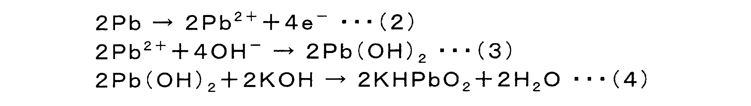
したがって、酸素センサーから、アノードガス拡散層を透過した酸素の量に比例する電流が出力される。この酸素センサーからの出力は、送信器及び受信器で送受信されて演算装置に出力される。そして、演算装置では、酸素センサーからの出力に基づいて、アノードガス拡散層を透過した酸素量を求め、この酸素量からアノードガス拡散層の酸素拡散係数を算出することができる。
Therefore, the oxygen sensor outputs a current proportional to the amount of oxygen transmitted through the anode gas diffusion layer. The output from the oxygen sensor is transmitted and received by the transmitter and the receiver and output to the computing device. Then, in the arithmetic unit, the amount of oxygen transmitted through the anode gas diffusion layer can be obtained based on the output from the oxygen sensor, and the oxygen diffusion coefficient of the anode gas diffusion layer can be calculated from the amount of oxygen.
ここで求められた酸素拡散係数を用いて、相対ガス拡散係数(Dre)を算出する。また、ここで得られた相対ガス拡散係数(Dre)に、バルクでの水蒸気拡散係数(Dbulk)2.57×10⁻⁵[m2/s](@300K)をかけた値が、水蒸気有効拡散係数(300K)となる。
The relative gas diffusion coefficient (D re ) is calculated using the oxygen diffusion coefficient obtained here. Also, the value obtained by multiplying the relative gas diffusion coefficient (D re ) obtained here by the water vapor diffusion coefficient (D bulk ) 2.57 × 10 −5 [m 2 / s] (@ 300 K) in bulk is It becomes the water vapor effective diffusion coefficient (300 K).
アノード微細多孔質層5aは、ドライアウト耐性(水蒸気拡散抵抗性)を発揮できるものであればいずれの材料で形成されてもよいが、好ましくは扁平状導電性材料を含むことが好ましい。これにより、アノード微細多孔質層の屈曲度、水蒸気輸送抵抗を向上できる。ここで、アノード微細多孔質層5aが扁平状導電性材料を含む場合の形態は、特に制限されないが、例えば、図3に示される形態が挙げられる。図3は、本発明の好ましい実施形態に係るアノード微細多孔質層の基本構成を示す概略断面図である。
The anode fine porous layer 5a may be formed of any material as long as it can exhibit dryout resistance (water vapor diffusion resistance), but preferably contains a flat conductive material. Thereby, the flexibility of the anode microporous layer and the water vapor transport resistance can be improved. Here, the form in the case where the anode microporous layer 5a contains a flat conductive material is not particularly limited, and for example, the form shown in FIG. 3 can be mentioned. FIG. 3 is a schematic cross-sectional view showing a basic configuration of an anode microporous layer according to a preferred embodiment of the present invention.
図3Aに示す実施形態では、アノード微細多孔質層5aが、扁平状導電性材料21及び必要であればバインダ(図示せず)から構成される。この場合には、扁平状導電性材料21がアノード微細多孔質層5aの面方向に沿った状態でほぼ平行に配向して、アノード微細多孔質層5aの厚さ/面方向の水蒸気の拡散・排出を抑制・防止し、面方向の導電性を確保する。これにより、水蒸気がアノード側から排出することを抑制・防止し、プロトン伝導性を維持するのに十分な固体高分子電解質膜及び触媒層の保水性を維持することができる。ゆえに、ドライ条件において問題となるドライアウトを抑制して、発電性能の低下を抑制・防止できる。
In the embodiment shown in FIG. 3A, the anode microporous layer 5a is comprised of a flat conductive material 21 and, if necessary, a binder (not shown). In this case, the flat conductive material 21 is oriented substantially in parallel along the surface direction of the anode fine porous layer 5a, and the diffusion of water vapor in the thickness / surface direction of the anode fine porous layer 5a Control and prevent discharge, and ensure surface conductivity. As a result, the water vapor can be suppressed or prevented from being discharged from the anode side, and the water retention of the solid polymer electrolyte membrane and the catalyst layer sufficient to maintain the proton conductivity can be maintained. Therefore, it is possible to suppress or prevent the deterioration of the power generation performance by suppressing the dryout which is a problem in the dry condition.
図3Bに示す実施形態では、アノード微細多孔質層5aが、扁平状導電性材料21、粒状導電性材料22及び必要であればバインダ(図示せず)から構成される。この場合には、扁平状導電性材料21がアノード微細多孔質層5aの面方向に沿った状態でほぼ平行に配向して、アノード微細多孔質層5aの厚さ/面方向の水蒸気の拡散・排出を抑制・防止し、面方向の導電性を確保する。これにより、水蒸気がアノード側から排出することを抑制・防止し、プロトン伝導性を維持するのに十分な固体高分子電解質膜及び触媒層の保水性を維持できる。また、粒状導電性材料22が導電パス材として扁平状導電性材料21間に介在する。これにより、アノード微細多孔質層5aの厚さ方向の抵抗を低減して導電性を向上することができる。同時に、粒状導電性材料22は厚さ及び面方向のガス透過性を向上させるスペーサー材としても機能しうる。このため、ガス(燃料ガス)をセパレータ側から良好に透過させることができる。ゆえに、ドライ条件において問題となるドライアウトを抑制して、発電性能の低下を抑制・防止すると共に、導電性を向上することができる。
In the embodiment shown in FIG. 3B, the anode microporous layer 5a is comprised of a flat conductive material 21, a particulate conductive material 22 and, if necessary, a binder (not shown). In this case, the flat conductive material 21 is oriented substantially in parallel along the surface direction of the anode fine porous layer 5a, and the diffusion of water vapor in the thickness / surface direction of the anode fine porous layer 5a Control and prevent discharge, and ensure surface conductivity. This suppresses or prevents water vapor from being discharged from the anode side, and can maintain the water retentivity of the solid polymer electrolyte membrane and the catalyst layer sufficient to maintain the proton conductivity. In addition, the granular conductive material 22 intervenes between the flat conductive materials 21 as a conductive pass material. Thereby, the resistance in the thickness direction of the anode fine porous layer 5a can be reduced to improve the conductivity. At the same time, the particulate conductive material 22 can also function as a spacer material to improve gas permeability in the thickness and in the surface direction. Therefore, the gas (fuel gas) can be favorably transmitted from the separator side. Therefore, while suppressing the dryout which becomes a problem in dry conditions, while suppressing and preventing the fall of electric power generation performance, electroconductivity can be improved.
図3Cに示す実施形態では、アノード微細多孔質層5aが、大きさが異なる扁平状導電性材料21,21’及び必要であればバインダ(図示せず)から構成される。この場合には、扁平状導電性材料21,21’がアノード微細多孔質層5aの面方向に沿った状態でほぼ平行に配向して、アノード微細多孔質層5aの厚さ/面方向の水蒸気の拡散・排出を抑制・防止し、面方向の導電性を確保する。これにより、水蒸気がアノード側から排出することを抑制・防止し、プロトン伝導性を維持するのに十分な固体高分子電解質膜及び触媒層の保水性を維持できる。また、大きさの小さな扁平状導電性材料21’が導電パス材として扁平状導電性材料21間に介在する。これにより、アノード微細多孔質層5aの厚さ方向の抵抗を低減して導電性を向上することができる。同時に、大きさの小さな扁平状導電性材料21’は厚さ及び面方向のガス透過性を向上させるスペーサー材としても機能しうる。このため、ガス(燃料ガス及び酸化剤ガス)をセパレータ側から良好に透過させることができる。ゆえに、ドライ条件において問題となるドライアウトを抑制して、発電性能の低下を抑制・防止すると共に、導電性を向上することができる。
In the embodiment shown in FIG. 3C, the anode microporous layer 5a is composed of flat conductive materials 21, 21 'of different sizes and, if necessary, a binder (not shown). In this case, the flat conductive material 21 and 21 'are oriented substantially in parallel along the surface direction of the anode fine porous layer 5a, and the water vapor in the thickness / plane direction of the anode fine porous layer 5a Control and prevent the diffusion and discharge of water, and ensure the conductivity in the surface direction. This suppresses or prevents water vapor from being discharged from the anode side, and can maintain the water retentivity of the solid polymer electrolyte membrane and the catalyst layer sufficient to maintain the proton conductivity. In addition, a flat conductive material 21 ′ having a small size is interposed between the flat conductive materials 21 as a conductive pass material. Thereby, the resistance in the thickness direction of the anode fine porous layer 5a can be reduced to improve the conductivity. At the same time, the flat conductive material 21 'having a small size can also function as a spacer material to improve the gas permeability in the thickness direction and the surface direction. Therefore, gas (fuel gas and oxidant gas) can be favorably permeated from the separator side. Therefore, while suppressing the dryout which becomes a problem in dry conditions, while suppressing and preventing the fall of electric power generation performance, electroconductivity can be improved.
図3Dに示す実施形態では、アノード微細多孔質層5aが、扁平状導電性材料21、大きさが異なる粒状導電性材料22,22’、及び必要であればバインダ(図示せず)から構成される。この場合には、扁平状導電性材料21がアノード微細多孔質層5aの面方向に沿った状態でほぼ平行に配向して、アノード微細多孔質層5aの厚さ/面方向の水蒸気の拡散・排出を抑制・防止し、面方向の導電性を確保する。これにより、水蒸気がアノード側から排出することを抑制・防止し、プロトン伝導性を維持するのに十分な固体高分子電解質膜及び触媒層の保水性を維持できる。また、粒状導電性材料22,22’が導電パス材として扁平状導電性材料21間に介在する。これにより、アノード微細多孔質層5aの厚さ方向の抵抗を低減して導電性を向上することができる。上記に加えて、大きさの大きな粒状導電性材料22’が厚さ及び面方向のガス透過性を向上させるスペーサー材としても機能しうる。このため、ガス(燃料ガス)をセパレータ側から良好に透過させることができる。これにより、低湿度条件下であっても、固体高分子電解質膜及び触媒層は十分量の水を確保することができる。ゆえに、ドライ条件において問題となるドライアウトを抑制して、発電性能の低下を抑制・防止すると共に、導電性を向上することができる。
In the embodiment shown in FIG. 3D, the anode microporous layer 5a is comprised of a flat conductive material 21, granular conductive materials 22, 22 'of different sizes, and, if necessary, a binder (not shown) Ru. In this case, the flat conductive material 21 is oriented substantially in parallel along the surface direction of the anode fine porous layer 5a, and the diffusion of water vapor in the thickness / surface direction of the anode fine porous layer 5a Control and prevent discharge, and ensure surface conductivity. This suppresses or prevents water vapor from being discharged from the anode side, and can maintain the water retentivity of the solid polymer electrolyte membrane and the catalyst layer sufficient to maintain the proton conductivity. Further, granular conductive materials 22 and 22 'are interposed between the flat conductive materials 21 as conductive pass materials. Thereby, the resistance in the thickness direction of the anode fine porous layer 5a can be reduced to improve the conductivity. In addition to the above, the large-sized granular conductive material 22 'can also function as a spacer material to improve the gas permeability in the thickness direction and the surface direction. Therefore, the gas (fuel gas) can be favorably transmitted from the separator side. Thereby, even under low humidity conditions, the solid polymer electrolyte membrane and the catalyst layer can secure a sufficient amount of water. Therefore, while suppressing the dryout which becomes a problem in dry conditions, while suppressing and preventing the fall of electric power generation performance, electroconductivity can be improved.
図3Eに示す実施形態では、アノード微細多孔質層5aが、大きさが異なる扁平状導電性材料21,21’、大きさの大きい粒状導電性材料22’及び必要であればバインダ(図示せず)から構成される。この場合には、扁平状導電性材料21,21’がアノード微細多孔質層5aの面方向に沿った状態でほぼ平行に配向して、アノード微細多孔質層5aの厚さ/面方向の水蒸気の拡散・排出を抑制・防止し、面方向の導電性を確保する。これにより、水蒸気がアノード側から排出することを抑制・防止し、プロトン伝導性を維持するのに十分な固体高分子電解質膜及び触媒層の保水性を維持できる。また、大きさの小さな扁平状導電性材料21’及び大きさの大きい粒状導電性材料22’が導電パス材として扁平状導電性材料21間に介在する。これにより、アノード微細多孔質層5aの厚さ方向の抵抗を低減して導電性を向上することができる。上記に加えて、大きさの小さな扁平状導電性材料21’及び大きさの小さい粒状導電性材料22が厚さ及び面方向のガス透過性を向上させるスペーサー材としても機能しうる。このため、ガス(燃料ガス)をセパレータ側から良好に透過させることができる。これにより、低湿度条件下であっても、固体高分子電解質膜及び触媒層は十分量の水を確保することができる。ゆえに、ドライ条件において問題となるドライアウトを抑制して、発電性能の低下を抑制・防止すると共に、導電性を向上することができる。
In the embodiment shown in FIG. 3E, the anode microporous layer 5a is formed of flat conductive materials 21 and 21 'having different sizes, granular conductive materials 22' having a large size, and a binder (not shown). It consists of. In this case, the flat conductive material 21 and 21 'are oriented substantially in parallel along the surface direction of the anode fine porous layer 5a, and the water vapor in the thickness / plane direction of the anode fine porous layer 5a Control and prevent the diffusion and discharge of water, and ensure the conductivity in the surface direction. This suppresses or prevents water vapor from being discharged from the anode side, and can maintain the water retentivity of the solid polymer electrolyte membrane and the catalyst layer sufficient to maintain the proton conductivity. In addition, a small-sized flat conductive material 21 ′ and a large-size granular conductive material 22 ′ intervene between the flat conductive materials 21 as a conductive pass material. Thereby, the resistance in the thickness direction of the anode fine porous layer 5a can be reduced to improve the conductivity. In addition to the above, the small-sized flat conductive material 21 'and the small-sized granular conductive material 22 can also function as a spacer material for improving the gas permeability in the thickness and the surface direction. Therefore, the gas (fuel gas) can be favorably transmitted from the separator side. Thereby, even under low humidity conditions, the solid polymer electrolyte membrane and the catalyst layer can secure a sufficient amount of water. Therefore, while suppressing the dryout which becomes a problem in dry conditions, while suppressing and preventing the fall of electric power generation performance, electroconductivity can be improved.
なお、上記図3に示されるアノード微細多孔質層の構造(扁平状導電性材料及び粒状導電性材料の組み合わせ例)は、代表例に過ぎず、これらに限定されない。例えば、図3Bに示したアノード微細多孔質層に、大きさの小さい扁平状導電性材料21’を組み合わせたり、さらに大きさの大きい粒状導電性材料22’を追加したりしてもよい。
The structure of the anode fine porous layer (a combination example of the flat conductive material and the granular conductive material) shown in FIG. 3 is only a representative example, and is not limited thereto. For example, the anode microporous layer shown in FIG. 3B may be combined with a flat conductive material 21 'having a smaller size, or may be added with a granular conductive material 22' having a larger size.
上記のうち、ドライアウト耐性(水蒸気拡散抵抗性)、導電性などを考慮すると、図3B~3Eの形態が好ましい。
Among the above, the forms of FIGS. 3B to 3E are preferable in consideration of dryout resistance (water vapor diffusion resistance), conductivity and the like.
本形態において、扁平状導電性材料は、アノード微細多孔質層の厚さ方向及び面方向のドライアウト耐性(水蒸気拡散抵抗性)の向上および面方向の抵抗低減(導電性向上)に寄与する。ここで、扁平状導電性材料の大きさは、アノード微細多孔質層5aの厚さ/面方向の水蒸気の拡散・排出を抑制・防止できれば、特に制限されない。具体的には、扁平状導電性材料の厚さが、0.05~1μmであることが好ましく、0.05~0.3μmであることがより好ましい。また、扁平状導電性材料のアスペクト比が、3を超えることが好ましく、10~1000であることがより好ましく、10~1000であることが特に好ましい。すなわち、アノード微細多孔質層は、厚さが0.05~1μmでありかつアスペクト比が10~1000である扁平状導電性材料を含むことが好ましい。このような形状の扁平状導電性材料であれば、扁平状導電性材料をアノード微細多孔質層の面方向に沿って配向して配置して、厚さ/面方向の水蒸気の拡散・排出を抑制・防止でき、輸送抵抗を向上できる。ゆえに、乾燥条件において、高分子電解質膜とアノード触媒層のドライアウトを効果的に抑制・防止できる。同時に、アノード微細多孔質層の面方向の導電性をも確保でき、また、アノード微細多孔質層の屈曲度を向上できる。本明細書において、扁平状導電性材料(および以下に規定される鱗片状黒鉛;以下同様)の厚さは、図4Aに示されるように、扁平状導電性材料を真横から見た場合の厚さ(図中の「H(μm)」)を意味する。なお、扁平状導電性材料の厚さが一定でない場合には、最大厚さを意図する。同様にして、扁平状導電性材料の平面直径は、図4Bに示されるように、扁平状導電性材料(鱗片状黒鉛)を真上から見た場合の平面直径(図中の「D(μm)」)を意味し、扁平状導電性材料(鱗片状黒鉛)の平面直径が一定でない場合には、最大平面直径を意図する。なお、扁平状導電性材料の平面直径は、公知の方法で測定できるが、本明細書では、レーザー回折・散乱法により測定される値を意味する。扁平状導電性材料の平面直径は、特に制限されないが、5~50μmであることが好ましい。このような大きさであれば、アノード微細多孔質層の厚さに影響を及ぼすことなく、アノード微細多孔質層の厚さ方向及び面方向のドライアウト耐性(水蒸気拡散抵抗性)を向上し、また、面方向の抵抗を低減できる(導電性を向上できる)。
In this embodiment, the flat conductive material contributes to the improvement of the dryout resistance (water vapor diffusion resistance) in the thickness direction and the surface direction of the anode fine porous layer and the reduction of the resistance in the surface direction (conductivity improvement). Here, the size of the flat conductive material is not particularly limited as long as the diffusion / discharge of water vapor in the thickness / surface direction of the anode fine porous layer 5 a can be suppressed / prevented. Specifically, the thickness of the flat conductive material is preferably 0.05 to 1 μm, and more preferably 0.05 to 0.3 μm. The aspect ratio of the flat conductive material is preferably more than 3, more preferably 10 to 1000, and particularly preferably 10 to 1000. That is, the anode fine porous layer preferably contains a flat conductive material having a thickness of 0.05 to 1 μm and an aspect ratio of 10 to 1000. If it is a flat conductive material having such a shape, the flat conductive material is oriented and arranged along the surface direction of the anode fine porous layer to diffuse / discharge water vapor in the thickness / surface direction. It can be suppressed / prevented and transport resistance can be improved. Therefore, under dry conditions, dryout of the polymer electrolyte membrane and the anode catalyst layer can be effectively suppressed / prevented. At the same time, the conductivity in the surface direction of the anode microporous layer can be secured, and the flexibility of the anode microporous layer can be improved. In the present specification, the thickness of the flat conductive material (and flaky graphite defined below; the same applies hereinafter) is the thickness when the flat conductive material is viewed from the side, as shown in FIG. 4A. (“H (μm)” in the figure). In the case where the thickness of the flat conductive material is not constant, the maximum thickness is intended. Similarly, the flat diameter of the flat conductive material is, as shown in FIG. 4B, the flat diameter (“D (μm in the figure) when the flat conductive material (scale-like graphite) is viewed from directly above “)), And where the flat diameter of the flat conductive material (flaky graphite) is not constant, the maximum flat diameter is intended. The flat diameter of the flat conductive material can be measured by a known method, but in the present specification, it means a value measured by a laser diffraction / scattering method. The flat diameter of the flat conductive material is not particularly limited, but is preferably 5 to 50 μm. With such a size, the dryout resistance (water vapor diffusion resistance) in the thickness direction and in the surface direction of the anode microporous layer can be improved without affecting the thickness of the anode microporous layer. In addition, the resistance in the surface direction can be reduced (the conductivity can be improved).
また、本明細書において、扁平状導電性材料のアスペクト比は、上記で求められた扁平状導電性材料の厚さ(H)に対する上記で求められた扁平状導電性材料の平面直径(D)の割合(D/H)として規定される。
In the present specification, the aspect ratio of the flat conductive material is the flat diameter (D) of the flat conductive material determined above with respect to the thickness (H) of the flat conductive material determined above. Is defined as the ratio (D / H) of
ここで、図3C、図3Eに示されるように、大きさの異なる扁平状導電性材料21,21’を使用する場合には、大きさの大きな扁平状導電性材料21および大きさの小さな扁平状導電性材料21’の大きさは、特に制限されず、上記したような厚さ及びアスペクト比を有することが好ましい。好ましい実施形態によると、大きさの大きな扁平状導電性材料21の厚さ及びアスペクト比は、上記扁平状導電性材料で記載したのと同様である。一方、大きさの小さな扁平状導電性材料21’の厚さは、0.05~1μmであることが好ましく、0.05~0.5μmであることがより好ましい。また、大きさの小さな扁平状導電性材料21’のアスペクト比は、1~100であることが好ましく、1~20であることがより好ましい。また、大きさの小さな扁平状導電性材料21’の平面直径は、特に制限されないが、0.01~30μmであることが好ましい。このような形状であれば、上記図3C、図3Eで記載される効果をより効果的に発揮することができる。
Here, as shown in FIGS. 3C and 3E, when flat conductive materials 21 and 21 'having different sizes are used, a flat conductive material 21 having a large size and a flat having a small size are used. The size of the conductive material 21 'is not particularly limited, and preferably has the thickness and aspect ratio as described above. According to a preferred embodiment, the thickness and aspect ratio of the large sized flat conductive material 21 are the same as described for the flat conductive material above. On the other hand, the thickness of the small-sized flat conductive material 21 'is preferably 0.05 to 1 μm, and more preferably 0.05 to 0.5 μm. The aspect ratio of the small-sized flat conductive material 21 ′ is preferably 1 to 100, and more preferably 1 to 20. The flat diameter of the small-sized flat conductive material 21 'is not particularly limited, but is preferably 0.01 to 30 μm. With such a shape, the effects described in FIGS. 3C and 3E can be more effectively exhibited.
また、本形態において、扁平状導電性材料は、アノード微細多孔質層5aの厚さ/面方向の水蒸気の拡散・排出を抑制・防止できれば、特に制限されない。具体的には、鱗片状黒鉛であることが好ましい。鱗片状黒鉛は、結晶性が高く、アスペクト比(平面直径D/厚さH)の大きなうろこ状の形状を有する。このような鱗片状黒鉛であれば、扁平状導電性材料をアノード微細多孔質層の面方向に沿って配向して配置して、厚さ/面方向の水蒸気の拡散・排出を抑制・防止できる。同時に、アノード微細多孔質層の面方向の導電性をも確保でき、また、アノード微細多孔質層の屈曲度を向上できる。上記に加えて、鱗片状黒鉛は、安価で高い導電性を有する上、効果的に発電性能を向上させることができる。すなわち、扁平状導電性材料は、厚さが0.05~1μmでありかつアスペクト比が10~1000である鱗片状黒鉛であることが特に好ましい。
Further, in the present embodiment, the flat conductive material is not particularly limited as long as the diffusion / discharge of water vapor in the thickness / surface direction of the anode fine porous layer 5a can be suppressed / prevented. Specifically, scale-like graphite is preferable. Flaky graphite has high crystallinity and has a large scale-like shape with an aspect ratio (planar diameter D / thickness H). With such scaly graphite, the flat conductive material can be oriented and disposed along the surface direction of the anode fine porous layer to suppress / prevent the diffusion / discharge of water vapor in the thickness / surface direction. . At the same time, the conductivity in the surface direction of the anode microporous layer can be secured, and the flexibility of the anode microporous layer can be improved. In addition to the above, scale-like graphite is inexpensive, has high conductivity, and can effectively improve power generation performance. That is, the flat conductive material is particularly preferably scale-like graphite having a thickness of 0.05 to 1 μm and an aspect ratio of 10 to 1000.
扁平状導電性材料が鱗片状黒鉛である場合の鱗片状黒鉛の比表面積(BET比表面積)は、特に制限されないが、好ましくは2000m2/g以下であり、より好ましくは15~1000m2/gである。このような比表面積の鱗片状黒鉛を扁平状導電性材料として使用することによって、アノード微細多孔質層5aの厚さ/面方向のドライアウト耐性(水蒸気拡散抵抗性)をさらに向上することができる。
The specific surface area (BET specific surface area) of scale-like graphite when the flat conductive material is scale-like graphite is not particularly limited, but is preferably 2000 m 2 / g or less, more preferably 15 to 1000 m 2 / g It is. By using scale-like graphite having such a specific surface area as the flat conductive material, the dryout resistance (water vapor diffusion resistance) of thickness / plane direction of the anode fine porous layer 5a can be further improved. .
扁平状導電性材料の配合量は、適度なドライアウト耐性(水蒸気拡散抵抗性)、導電性を達成できれば特に制限されない。具体的には、扁平状導電性材料の配合量(固形分量)は、アノード微細多孔質層を構成する全成分に対して、10~95重量%であることが好ましく、15~85重量%であることがより好ましく、40~70重量%であることがさらにより好ましい。なお、上記扁平状導電性材料の配合量は、扁平状導電性材料として大きさの異なる扁平状導電性材料21,21’を使用した場合には、これらの扁平状導電性材料の合計配合量とする。このような量であれば、十分量の扁平状導電性材料をアノード微細多孔質層の面方向に沿って配置して、厚さ/面方向の水蒸気の拡散・排出を抑制・防止できる。また、アノード微細多孔質層の面方向の導電性をも確保でき、また、アノード微細多孔質層の屈曲度を向上できる。
The blending amount of the flat conductive material is not particularly limited as long as it can achieve appropriate dry-out resistance (water vapor diffusion resistance) and conductivity. Specifically, the blending amount (solid content) of the flat conductive material is preferably 10 to 95% by weight, and 15 to 85% by weight with respect to all the components constituting the anode fine porous layer. Some are more preferable, and 40 to 70% by weight is even more preferable. In addition, the compounding quantity of the said flat-shaped electroconductive material is the total compounding quantity of these flat-shaped electroconductive materials, when using flat-shaped electroconductive materials 21 and 21 'of which sizes differ as a flat-shaped electroconductive material I assume. With such an amount, a sufficient amount of the flat conductive material can be disposed along the surface direction of the anode fine porous layer to suppress / prevent the diffusion / discharge of water vapor in the thickness / surface direction. In addition, the conductivity in the surface direction of the anode fine porous layer can be secured, and the flexibility of the anode fine porous layer can be improved.
本形態では、アノード微細多孔質層5aは、扁平状導電性材料に加えて、粒状導電性材料を含みうる。この際、粒状導電性材料としては、特に制限されないが、例えば、オイルファーネスブラック、アセチレンブラック、ケッチェンブラック、サーマルブラック、チャンネルブラック、ランプブラック等のカーボンブラック、小径の鱗片状黒鉛、炭素繊維などが挙げられる。また、粒状導電性材料は、自ら調製してもよいし、市販の導電性材料(炭素材料)を用いてもよい。市販の導電性材料(炭素材料)としては、バルカン(登録商標)、ケッチェンブラック(登録商標)、ブラックパール(登録商標)などが挙げられる。また、カーボンブラックは、黒鉛化処理が施されていてもよい。この際、上記粒状導電性材料は、単独で使用されてもあるいは2種以上の混合物の形態で使用されてもよい。このうち、図3Dに示されるように、大きさの異なる粒状導電性材料22,22’を使用する場合の、大きさの大きな粒状導電性材料22は、カーボンブラックが好ましく、アセチレンブラック、ケッチェンブラックがより好ましい。また、大きさの小さな粒状導電性材料22’は、黒鉛化処理されたカーボンブラックが好ましい。
In the present embodiment, the anode microporous layer 5a may include a particulate conductive material in addition to the flat conductive material. At this time, the particulate conductive material is not particularly limited, but, for example, carbon black such as oil furnace black, acetylene black, ketjen black, thermal black, channel black, lamp black, small scale flake graphite, carbon fiber, etc. Can be mentioned. In addition, the particulate conductive material may be prepared by itself or a commercially available conductive material (carbon material) may be used. Commercially available conductive materials (carbon materials) include Vulcan (registered trademark), ketjen black (registered trademark), black pearl (registered trademark) and the like. In addition, carbon black may be subjected to graphitization treatment. At this time, the particulate conductive material may be used alone or in the form of a mixture of two or more. Among them, as shown in FIG. 3D, carbon black is preferable for the large-size granular conductive material 22 in the case of using granular conductive materials 22 and 22 'having different sizes, and acetylene black and ketjen are preferable. Black is more preferred. In addition, it is preferable that the small-sized granular conductive material 22 'be graphitized carbon black.
また、粒状導電性材料の大きさもまた特に制限されない。例えば、図3Dに示されるように、大きさの異なる粒状導電性材料22,22’を使用する場合の、大きさの大きな粒状導電性材料22は、平均粒径(平均一次粒径、直径)が、10nm以上5μm未満であることが好ましく、0.05~20μmであることがより好ましい。また、大きさの小さな粒状導電性材料22’の大きさは、平均粒径が、1~10nmであることが好ましく、0.05~5nmであることがより好ましい。この際、粒状導電性材料の大きさは、公知の方法によって測定できるが、本明細書では、特に言及のない限り、走査型電子顕微鏡(SEM)や透過型電子顕微鏡(TEM)などの観察手段を用い、数~数十視野中に観察される粒子の粒子径の平均値として算出される値を採用するものとする。また、「粒径」とは、粒子の輪郭線上の任意の2点間の距離のうち、最大の距離を意味するものとする。なお、本明細書において、「粒状導電性材料」とは、アスペクト比(平面直径D/厚さH)が1~3程度のものをいう。
Also, the size of the particulate conductive material is also not particularly limited. For example, as shown in FIG. 3D, when using granular conductive materials 22 and 22 'of different sizes, large-size granular conductive materials 22 have an average particle size (average primary particle size, diameter). Is preferably 10 nm or more and less than 5 μm, and more preferably 0.05 to 20 μm. The size of the small-sized granular conductive material 22 'is preferably 1 to 10 nm, more preferably 0.05 to 5 nm, as the average particle diameter. At this time, the size of the particulate conductive material can be measured by a known method, but in the present specification, unless otherwise specified, an observation means such as a scanning electron microscope (SEM) or a transmission electron microscope (TEM) A value calculated as an average value of particle diameters of particles observed in several to several tens of visual fields is used. Also, “particle size” means the largest distance among the distance between any two points on the contour line of the particle. In the present specification, the “particulate conductive material” refers to one having an aspect ratio (planar diameter D / thickness H) of about 1 to 3.
粒状導電性材料がカーボンブラックである場合のカーボンブラックの比表面積(BET比表面積)は、特に制限されないが、好ましくは2000m2/g以上であり、より好ましくは15~1000m2/gである。このような比表面積のカーボンブラックを粒状導電性材料として使用することによって、アノード微細多孔質層5aの厚さ方向の抵抗を低減して導電性をさらに向上することができる。
The specific surface area (BET specific surface area) of carbon black when the particulate conductive material is carbon black is not particularly limited, but is preferably 2000 m 2 / g or more, and more preferably 15 to 1000 m 2 / g. By using carbon black having such a specific surface area as the particulate conductive material, the resistance in the thickness direction of the anode fine porous layer 5a can be reduced to further improve the conductivity.
粒状導電性材料の配合量は、適度なガス透過性向上、導電性向上を達成できれば特に制限されない。具体的には、大きさの小さな粒状導電性材料の配合量(固形分量)は、アノード微細多孔質層を構成する全成分に対して、1~35重量%であることが好ましい。なお、上記粒状導電性材料の配合量は、粒状導電性材料として大きさの異なる扁平状導電性材料22,22’を使用した場合には、これらの粒状導電性材料の合計配合量とする。このような量で配合された粒状導電性材料は、導電パス材として扁平状導電性材料間に介在して、アノード微細多孔質層の厚さ方向の抵抗を低減して導電性を向上することができる。また、厚さ及び面方向のガス透過性を向上させるスペーサー材としても機能し、良好なガス透過性を達成しうる。特に、粒状導電性材料としてアセチレンブラックを使用する場合には、アセチレンブラックの配合量は、アノード微細多孔質層を構成する全成分に対して、5~40重量%であることがより好ましい。このような量であれば、十分な接触点及び接触面積を稼いで導電性を向上することができる。また、厚さ及び面方向のガス透過性を向上させるスペーサー材としても機能し、良好なガス透過性を達成できる。また、粒状導電性材料としてケッチェンブラックを用いる際には、ケッチェンブラックの配合量は、アノード微細多孔質層を構成する全成分に対して、1~20重量%であることが好ましく、3~15重量%であることがより好ましく、3~5重量%であることがさらにより好ましい。このような量であれば、十分な接触点及び接触面積を稼いで導電性を向上することができる。また、厚さ及び面方向のガス透過性を向上させるスペーサー材としても機能し、良好なガス透過性を達成できる。
The compounding amount of the particulate conductive material is not particularly limited as long as it can achieve appropriate gas permeability improvement and conductivity improvement. Specifically, the blending amount (solid content) of the small-sized granular conductive material is preferably 1 to 35% by weight with respect to all the components constituting the anode microporous layer. In addition, the compounding quantity of the said granular conductive material is made into the total compounding quantity of these granular conductive materials, when flat-shaped conductive material 22 and 22 'from which a magnitude | size differs as a granular conductive material is used. The particulate conductive material blended in such an amount is interposed between the flat conductive materials as a conductive pass material to reduce the resistance in the thickness direction of the anode fine porous layer to improve the conductivity. Can. Moreover, it functions as a spacer material that improves the gas permeability in the thickness and plane direction, and can achieve good gas permeability. In particular, when acetylene black is used as the particulate conductive material, the blending amount of acetylene black is more preferably 5 to 40% by weight with respect to all components constituting the anode fine porous layer. With such an amount, sufficient contact points and contact area can be obtained to improve conductivity. Moreover, it functions also as a spacer material which improves the gas permeability of thickness and a surface direction, and can achieve favorable gas permeability. When ketjen black is used as the particulate conductive material, the blending amount of ketjen black is preferably 1 to 20% by weight with respect to all the components constituting the anode fine porous layer, and 3 It is more preferably ~ 15 wt% and even more preferably 3-5 wt%. With such an amount, sufficient contact points and contact area can be obtained to improve conductivity. Moreover, it functions also as a spacer material which improves the gas permeability of thickness and a surface direction, and can achieve favorable gas permeability.
また、上記において、必要であれば使用できるバインダとしては、特に制限されず、公知のバインダが使用できる。好ましくは、扁平状導電性材料、粒状導電性材料等の導電性同士を結着して、アノード微細多孔質層の強度を確保する機能を有するものであって、撥水剤としての機能を兼ね備えていることが望ましい。このようなバインダとしては、PTFE(ポリテトラフルオロエチレン)、テトラフルオロエチレン-ヘキサフルオロプロピレン共重合体(FEP)、テトラフルオロエチレン-パーフルオロアルキルビニルエーテル共重合体(PFA)等が挙げられる。また、バインダの配合量(固形分量)は、上記したような効果を奏する量であれば特に制限されないが、アノード微細多孔質層を構成する全成分に対して、5~40重量%であることが好ましい。このような量であれば、導電性同士を結着して、アノード微細多孔質層の十分な強度を確保でき、また、適度な撥水性を発揮できる。
In the above, the binder that can be used if necessary is not particularly limited, and a known binder can be used. Preferably, it has a function of securing the strength of the anode microporous layer by bonding conductive materials such as flat conductive material and granular conductive material to each other, and also has a function as a water repellent. Is desirable. As such a binder, PTFE (polytetrafluoroethylene), tetrafluoroethylene-hexafluoropropylene copolymer (FEP), tetrafluoroethylene-perfluoroalkyl vinyl ether copolymer (PFA) and the like can be mentioned. The amount of binder (solid content) is not particularly limited as long as it exerts the above-mentioned effects, but it is 5 to 40% by weight with respect to all the components constituting the anode fine porous layer. Is preferred. With such an amount, the conductive materials can be bound to each other to ensure sufficient strength of the anode fine porous layer and to exhibit appropriate water repellency.
本形態のアノードガス拡散層は、アノード微細多孔質層5aがアノードガス拡散層基材6a(またはアノードガス拡散層基材6aに配置されたアノード中間層(MPL)7a)上に配置される構造を有する。このような構造を有することにより、本発明のMEAは、ドライアウト耐性とフラッディング耐性とを両立でき、アノード側でドライアウト耐性(水蒸気拡散抵抗性)を効果的に発揮できる。ここで、アノードガス拡散層のドライアウト耐性(水蒸気拡散抵抗性)は、ドライアウト耐性を十分発揮できる程度であれば特に制限されないが、水蒸気有効拡散係数(300K)が、2×10⁻⁶~6.0×10⁻⁶[m2/s]であることが好ましく、3.0×10-6~6.0×10-6[m2/s]であることがより好ましい。上記したようなガス拡散係数を有するアノードガス拡散層は、アノード側でドライアウト耐性(水蒸気拡散抵抗性)に優れる。
In the anode gas diffusion layer of this embodiment, the anode fine porous layer 5a is disposed on the anode gas diffusion layer substrate 6a (or the anode intermediate layer (MPL) 7a disposed on the anode gas diffusion layer substrate 6a). Have. By having such a structure, the MEA of the present invention can achieve both dryout resistance and flooding resistance, and can effectively exhibit dryout resistance (water vapor diffusion resistance) on the anode side. Here, the dry out resistance (water vapor diffusion resistance) of the anode gas diffusion layer is not particularly limited as long as the dry out resistance can be sufficiently exhibited, but the water vapor effective diffusion coefficient (300 K) is 2 × 10 −6 to is preferably 6.0 × 10 -6 [m 2 / s], and more preferably 3.0 × 10 -6 ~ 6.0 × 10 -6 [m 2 / s]. The anode gas diffusion layer having the gas diffusion coefficient as described above is excellent in dryout resistance (water vapor diffusion resistance) on the anode side.
アノード微細多孔質層の形成方法は特に制限されない。以下に、本発明に係るアノード微細多孔質層の形成方法の好ましい実施形態を説明するが、本発明は下記形態に限定されない。
The method of forming the anode microporous layer is not particularly limited. Hereinafter, a preferred embodiment of the method for forming an anode microporous layer according to the present invention will be described, but the present invention is not limited to the following embodiment.
まず、扁平状導電性材料、および必要に応じて粒状導電性材料、バインダ、界面活性剤、増粘剤を含むインクを調製する。次に、このインクを攪拌、脱泡処理した後、耐熱性保持シート上に塗布し、乾燥、焼成を行って、アノード微細多孔質層を耐熱性保持シート上に形成する。ここで、耐熱性保持シートとしては、PTFE(ポリテトラフルオロエチレン)シート、PET(ポリエチレンテレフタレート)シート等の、ポリエステルシート、ポリイミドシート、ポリプロピレンシート、ポリエチレンシート、ポリスルホンシート、ポリテトラフルオロエチレンシートなどの公知のシートが使用できる。これらのうち、ポリイミドシートを好適に用いることができる。また、耐熱性保持シートの厚さは、特に制限されないが、10~100μm程度であることが好ましい。または、耐熱性保持シートの代わりに、ガス拡散層基材または中間層が予め形成されたガス拡散層基材(MPL付GDL)を使用してもよい。
First, an ink containing a flat conductive material, and optionally, a granular conductive material, a binder, a surfactant, and a thickener is prepared. Next, the ink is stirred and defoamed, then applied on a heat resistant holding sheet, dried and fired to form an anode fine porous layer on the heat resistant holding sheet. Here, as a heat resistant holding sheet, a polyester sheet such as a PTFE (polytetrafluoroethylene) sheet or a PET (polyethylene terephthalate) sheet, a polyimide sheet, a polypropylene sheet, a polyethylene sheet, a polysulfone sheet, a polytetrafluoroethylene sheet, etc. Known sheets can be used. Among these, a polyimide sheet can be used suitably. The thickness of the heat resistant holding sheet is not particularly limited, but is preferably about 10 to 100 μm. Alternatively, instead of the heat resistant holding sheet, a gas diffusion layer substrate or a gas diffusion layer substrate (GDL with MPL) in which an intermediate layer is previously formed may be used.
上記方法において、乾燥条件は、特に制限されないが、例えば、80~120℃で1~60分間の条件が好ましい。また、焼成条件もまた特に制限されないが、例えば、120~350℃で5~60分間の条件が好ましい。
In the above method, the drying conditions are not particularly limited, but for example, conditions of 80 to 120 ° C. for 1 to 60 minutes are preferable. The firing conditions are also not particularly limited, but for example, the conditions of 120 to 350 ° C. for 5 to 60 minutes are preferable.
次に、アノード微細多孔質層を耐熱性保持シートから剥がし、例えば、ホットプレスなどによって、ガス拡散層基材または中間層が予め形成されたガス拡散層基材上に積層することによって、アノードガス拡散層を得ることができる。または、上記方法において、ガス拡散層基材または中間層が予め形成されたガス拡散層基材を耐熱性保持シートとして使用して、インクを、直接、上記ガス拡散層基材または中間層が予め形成されたガス拡散層基材の中間層側に塗布し、乾燥、焼成を行って、アノード微細多孔質層を耐熱性保持シート上に形成して、アノードガス拡散層を得てもよい。上記方法において、乾燥・焼成条件は、特に制限されないが、上記と同様の条件が好ましく適用される。
Next, the anode fine porous layer is peeled off from the heat resistant holding sheet, and the anode gas is laminated on the gas diffusion layer base on which the gas diffusion layer base or the intermediate layer is previously formed by, for example, hot pressing. A diffusion layer can be obtained. Alternatively, in the above method, using the gas diffusion layer base material or the gas diffusion layer base material on which the intermediate layer is previously formed as a heat resistant holding sheet, the ink is directly coated with the gas diffusion layer base material or intermediate layer It may be applied to the middle layer side of the formed gas diffusion layer substrate, dried and fired to form an anode fine porous layer on the heat resistant holding sheet to obtain an anode gas diffusion layer. In the above method, the drying and firing conditions are not particularly limited, but the same conditions as described above are preferably applied.
(カソード微細多孔質層)
上述したように、カソード微細多孔質層5cは、カソード微細多孔質層5c及びカソードガス拡散層基材6cを有し、必要であれば、カソード微細多孔質層5cとカソードガス拡散層基材6cとの間に、カソード中間層(MPL)7cをさらに有する。 (Cathode microporous layer)
As described above, thecathode microporous layer 5c has the cathode microporous layer 5c and the cathode gas diffusion layer base 6c, and if necessary, the cathode microporous layer 5c and the cathode gas diffusion layer base 6c. And a cathode intermediate layer (MPL) 7c.
上述したように、カソード微細多孔質層5cは、カソード微細多孔質層5c及びカソードガス拡散層基材6cを有し、必要であれば、カソード微細多孔質層5cとカソードガス拡散層基材6cとの間に、カソード中間層(MPL)7cをさらに有する。 (Cathode microporous layer)
As described above, the
カソード微細多孔質層5cの相対ガス拡散係数は、上記したように、アノード微細多孔質層5aの相対ガス拡散係数より0.05[-]以上大きければ特に制限されない。フラッディング耐性を考慮すると、カソード微細多孔質層5cの相対ガス拡散係数は、0.1~0.8[-]であることが好ましく、0.2~0.5[-]であることがより好ましい。このような範囲であれば、カソードで生成した水はカソード微細多孔質層5cを良好に通過して、GDL、セパレータを介して排出される。ゆえに、湿潤条件であってもMEA内からの水を排出させて(カソードフラッディングを悪化させずに)、フラッディング耐性を向上させることができる。一方、アノード側では、アノード微細多孔質層5aが、水/水蒸気がアノード微細多孔質層を透過することをより効果的に抑制・防止する。このため、ドライ(低湿度)条件であっても、水がGDL、セパレータを介して排出することを抑制・防止し、プロトン伝導性を維持するのに十分な量の水を固体高分子電解質膜や触媒層に確保できる。ゆえに、ドライ条件において問題となるドライアウトを抑制して、発電性能の低下を抑制・防止できる。したがって、本発明のMEAは、ドライアウト耐性及びフラッディング耐性双方をより両立できる。ここで、カソード微細多孔質層5cの相対ガス拡散係数を上記したように制御する方法は特に制限されない。好ましくは、下記に詳述するように、カソード微細多孔質層5cに粒状導電性材料を使用することによって達成できる。
The relative gas diffusion coefficient of the cathode fine porous layer 5c is not particularly limited as long as it is larger than the relative gas diffusion coefficient of the anode fine porous layer 5a by 0.05 [-] or more as described above. In consideration of the flooding resistance, the relative gas diffusion coefficient of the cathode microporous layer 5c is preferably 0.1 to 0.8 [-], more preferably 0.2 to 0.5 [-]. preferable. Within such a range, the water generated at the cathode passes through the cathode fine porous layer 5 c well and is discharged through the GDL and the separator. Therefore, even under wet conditions, water from within the MEA can be discharged (without deteriorating cathode flooding) to improve flooding resistance. On the other hand, on the anode side, the anode fine porous layer 5a more effectively suppresses and prevents water / steam from permeating the anode fine porous layer. For this reason, even under dry (low humidity) conditions, the amount of water sufficient to suppress and prevent the water from being discharged through the GDL and separator is sufficient to maintain proton conductivity. And can be secured in the catalyst layer. Therefore, it is possible to suppress or prevent the deterioration of the power generation performance by suppressing the dryout which is a problem in the dry condition. Therefore, the MEA of the present invention is more compatible with both dryout resistance and flooding resistance. Here, the method of controlling the relative gas diffusion coefficient of the cathode fine porous layer 5c as described above is not particularly limited. Preferably, this can be achieved by using a particulate conductive material for the cathode microporous layer 5c, as described in detail below.
カソード微細多孔質層5cの厚さは、カソードで生成した水を効率よく排出して、フラッディング耐性を発揮できる程度であれば制限されない。好ましくは、カソード微細多孔質層5cの厚さは、10~100μmであり、20~80μmであることがより好ましい。このような厚さにすることで、カソードで生成した水は、カソード側のGDL、セパレータを介して排出される。ゆえに、湿潤条件であってもMEA内からの水を排出させて(カソードフラッディングを悪化させずに)、フラッディング耐性を向上させることができる。
The thickness of the cathode fine porous layer 5c is not limited as long as the water generated at the cathode can be efficiently discharged and flooding resistance can be exhibited. Preferably, the thickness of the cathode microporous layer 5c is 10 to 100 μm, and more preferably 20 to 80 μm. With such a thickness, water generated at the cathode is discharged through the GDL on the cathode side and the separator. Therefore, even under wet conditions, water from within the MEA can be discharged (without deteriorating cathode flooding) to improve flooding resistance.
カソード微細多孔質層5cの屈曲度は、塑性変形を抑制・防止できる程度であれば制限されない。好ましくは、カソード微細多孔質層5cの屈曲度は、1~15であり、1.5~10であることがより好ましく、1.8~8であることがより好ましく、3~6であることがさらにより好ましい。このような屈曲度にすることで、スタック組み付け時の面方向の圧縮力に対する曲げ応力を緩和し、カソード微細多孔質層の塑性変形を抑制・防止できる。
The bending degree of the cathode fine porous layer 5c is not limited as long as it can suppress and prevent plastic deformation. Preferably, the tonicity of the cathode microporous layer 5c is 1 to 15, more preferably 1.5 to 10, still more preferably 1.8 to 8, and 3 to 6. Is even more preferred. With such a degree of inflection, it is possible to relieve the bending stress to the compressive force in the surface direction at the time of stack assembly, and to suppress or prevent the plastic deformation of the cathode fine porous layer.
カソード微細多孔質層5cの空隙率は、フラッディング耐性を発揮できる程度であれば制限されない。好ましくは、カソード微細多孔質層5cの空隙率は、40~80%であり、50~75%であることがより好ましい。このような空隙率にすることで、カソードで生成した水は、カソード側のGDL、セパレータを介して効率よく排出される。ゆえに、湿潤条件であってもMEA内からの水を排出させて(カソードフラッディングを悪化させずに)、フラッディング耐性をより向上させることができる。
The porosity of the cathode fine porous layer 5c is not limited as long as it can exhibit flooding resistance. Preferably, the porosity of the cathode microporous layer 5c is 40 to 80%, more preferably 50 to 75%. With such a porosity, water generated at the cathode is efficiently discharged through the GDL on the cathode side and the separator. Therefore, even under wet conditions, water from the inside of the MEA can be discharged (without deteriorating cathode flooding) to further improve the flooding resistance.
カソード微細多孔質層5cの水蒸気有効拡散係数(300K)は、フラッディング耐性を発揮できる程度であれば制限されない。好ましくは、カソード微細多孔質層5cの水蒸気有効拡散係数(300K)は、1.5×10⁻⁶~6.0×10⁻⁵[m2/s]であり、5.0×10-6~5.0×10-5[m2/s]であることがより好ましく、1.0×10-5~3.0×10-5[m2/s]であることがさらにより好ましい。このような水蒸気有効拡散係数(300K)であれば、カソードで生成した水は、カソード側のGDL、セパレータを介して効率よく排出される。ゆえに、湿潤条件であってもMEA内からの水を排出させて(カソードフラッディングを悪化させずに)、フラッディング耐性をより向上させることができる。
The water vapor effective diffusion coefficient (300 K) of the cathode fine porous layer 5c is not limited as long as it can exhibit flooding resistance. Preferably, the water vapor effective diffusion coefficient (300 K) of the cathode microporous layer 5 c is 1.5 × 10 −6 to 6.0 × 10 −5 [m 2 / s], and is 5.0 × 10 −6. It is more preferably about 5.0 × 10 −5 [m 2 / s], and still more preferably 1.0 × 10 −5 to 3.0 × 10 −5 [m 2 / s]. With such a water vapor effective diffusion coefficient (300 K), water generated at the cathode is efficiently discharged through the GDL on the cathode side and the separator. Therefore, even under wet conditions, water from the inside of the MEA can be discharged (without deteriorating cathode flooding) to further improve the flooding resistance.
カソード微細多孔質層5cは、フラッディング耐性を発揮できるものであればいずれの材料で形成されてもよいが、粒状導電性材料、より好ましくはカーボン粒子を含むことが好ましい。これにより、カソードで生成した水は粒子間の空隙を通過して、系外に排出されうる。ここで、カーボン粒子としては、特に限定されず、カーボンブラック、黒鉛(粒状黒鉛を含む)、膨張黒鉛などの従来公知の材料が適宜採用されうる。なかでも、電子伝導性に優れ、比表面積が大きいことから、オイルファーネスブラック、チャネルブラック、ランプブラック、サーマルブラック、アセチレンブラックなどのカーボンブラックが好ましく用いられうる。かようなカーボン粒子は、市販品を用いることができ、キャボット社製バルカンXC-72、バルカンP、ブラックパールズ880、ブラックパールズ1100、ブラックパールズ1300、ブラックパールズ2000、リーガル400、ライオン社製ケッチェンブラックEC、三菱化学社製#3150、#3250などのオイルファーネスブラック;電気化学工業社製デンカブラックなどのアセチレンブラック等が挙げられる。また、カーボンブラックのほか、天然の黒鉛、ピッチ、コークス、ポリアクリロニトリル、フェノール樹脂、フラン樹脂などの有機化合物から得られる人工黒鉛や炭素などであってもよい。また、耐食性などを向上させるために、前記カーボン粒子に黒鉛化処理などの加工を行ってもよい。この際、上記材料は、単独で使用されてもあるいは2種以上の混合物の形態で使用されてもよい。
The cathode fine porous layer 5c may be formed of any material as long as it can exhibit flooding resistance, but preferably contains a particulate conductive material, more preferably carbon particles. Thus, the water generated at the cathode can pass through the gaps between the particles and be discharged out of the system. Here, the carbon particles are not particularly limited, and conventionally known materials such as carbon black, graphite (including granular graphite), expanded graphite and the like may be appropriately adopted. Among them, carbon black such as oil furnace black, channel black, lamp black, thermal black and acetylene black can be preferably used because of excellent electron conductivity and large specific surface area. Such carbon particles may be commercially available products, and may be Cabot Vulcan XC-72, Vulcan P, Black Pearls 880, Black Pearls 1100, Black Pearls 1300, Black Pearls 2000, Regal 400, Lion Ketjen Black EC, oil furnace black such as Mitsubishi Chemical's # 3150, # 3250; acetylene black such as Denka Black manufactured by Denki Kagaku Kogyo Co., Ltd. In addition to carbon black, artificial graphite or carbon obtained from organic compounds such as natural graphite, pitch, coke, polyacrylonitrile, phenol resin, furan resin, etc. may be used. Moreover, in order to improve corrosion resistance etc., processing such as graphitization may be performed on the carbon particles. At this time, the above materials may be used alone or in the form of a mixture of two or more.
また、カーボン粒子の粒径は、フラッディング耐性を発揮できる程度であれば制限されない。好ましくは、カーボン粒子の平均粒径(平均一次粒径、直径)が、10nm以上5μm未満であることが好ましく、10~500nmであることがより好ましい。カーボン粒子の大きさは、公知の方法によって測定できるが、本明細書では、特に言及のない限り、上記粒状導電性材料の平均粒径と同様の定義である。
In addition, the particle diameter of the carbon particles is not limited as long as it can exhibit the flooding resistance. Preferably, the average particle size (average primary particle size, diameter) of the carbon particles is 10 nm or more and less than 5 μm, and more preferably 10 to 500 nm. The size of the carbon particles can be measured by a known method, but in the present specification, unless otherwise stated, the definition is the same as the average particle size of the above-mentioned particulate conductive material.
カーボン粒子の比表面積(BET比表面積)は、特に制限されないが、好ましくは10~2000m2/g以上であり、より好ましくは20~1000m2/gである。このような比表面積のカーボン粒子をカソード微細多孔質層に使用することによって、カソード微細多孔質層5cの厚さ方向の抵抗を低減して導電性をさらに向上することができる。
The specific surface area (BET specific surface area) of the carbon particles is not particularly limited, but is preferably 10 to 2000 m 2 / g or more, and more preferably 20 to 1000 m 2 / g. By using carbon particles having such a specific surface area for the cathode microporous layer, the resistance in the thickness direction of the cathode microporous layer 5c can be reduced to further improve the conductivity.
カーボン粒子の配合量は、適度なガス透過性向上、導電性向上を達成できれば特に制限されない。具体的には、カーボン粒子の配合量(固形分量)は、カソード微細多孔質層を構成する全成分に対して、40~90重量%であることが好ましく、50~85重量%であることがより好ましい。このような量で配合されたカーボン粒子は、導電パス材として十分な導電性をカソード微細多孔質層に付与し、カソード微細多孔質層の厚さ方向の抵抗を低減して導電性を向上することができる。また、水/水蒸気および酸化剤ガスが良好にカーボン粒子間を通過して、厚さ及び面方向のガス透過性を向上し、良好なガス透過性を達成しうる。特に、カーボン粒子としてアセチレンブラックを使用する場合には、アセチレンブラックの配合量は、カソード微細多孔質層を構成する全成分に対して、50~85重量%であることがより好ましい。このような量であれば、十分な接触点及び接触面積を稼いで導電性を向上することができる。また、水/水蒸気および酸化剤ガスが良好にカーボン粒子間を通過して、厚さ及び面方向のガス透過性を向上し、良好なガス透過性を達成できる。また、カーボン粒子としてケッチェンブラックを用いる際には、ケッチェンブラックの配合量は、カソード微細多孔質層を構成する全成分に対して、50~85重量%であることがより好ましい。このような量であれば、十分な接触点及び接触面積を稼いで導電性を向上することができる。また、水/水蒸気および酸化剤ガスが良好にカーボン粒子間を通過して、厚さ及び面方向のガス透過性を向上し、良好なガス透過性を達成できる。
The compounding amount of the carbon particles is not particularly limited as long as appropriate gas permeability improvement and conductivity improvement can be achieved. Specifically, the content of carbon particles (solid content) is preferably 40 to 90% by weight, and more preferably 50 to 85% by weight, with respect to all the components constituting the cathode fine porous layer. More preferable. The carbon particles compounded in such an amount impart conductivity to the cathode fine porous layer sufficient as a conductive path material, reduce the resistance in the thickness direction of the cathode fine porous layer, and improve the conductivity. be able to. In addition, water / steam and oxidant gas pass well between the carbon particles to improve the gas permeability in the thickness and plane direction and achieve good gas permeability. In particular, when acetylene black is used as carbon particles, the blending amount of acetylene black is more preferably 50 to 85% by weight with respect to all the components constituting the cathode fine porous layer. With such an amount, sufficient contact points and contact area can be obtained to improve conductivity. In addition, the water / steam and the oxidant gas can be favorably passed between the carbon particles to improve the gas permeability in the thickness direction and the surface direction, thereby achieving the good gas permeability. When ketjen black is used as the carbon particles, the blending amount of ketjen black is more preferably 50 to 85% by weight with respect to all the components constituting the cathode fine porous layer. With such an amount, sufficient contact points and contact area can be obtained to improve conductivity. In addition, the water / steam and the oxidant gas can be favorably passed between the carbon particles to improve the gas permeability in the thickness direction and the surface direction, thereby achieving the good gas permeability.
また、上記において、必要であれば使用できるバインダとしては、特に制限されず、公知のバインダが使用できる。好ましくは、上記カソード微細多孔質層での例示と同様のものが使用できる。また、バインダの配合量(固形分量)は、上記したような効果を奏する量であれば特に制限されないが、カソード微細多孔質層を構成する全成分に対して、10~60重量%であることが好ましい。このような量であれば、導電性同士を結着して、カソード微細多孔質層の十分な強度を確保でき、また、適度な撥水性を発揮できる。
In the above, the binder that can be used if necessary is not particularly limited, and a known binder can be used. Preferably, the same ones as exemplified in the above-mentioned cathode microporous layer can be used. The amount of binder (solid content) is not particularly limited as long as it exerts the above-mentioned effects, but it is 10 to 60% by weight based on all components constituting the cathode fine porous layer. Is preferred. With such an amount, the conductive materials can be bound to each other to ensure sufficient strength of the cathode fine porous layer and to exhibit appropriate water repellency.
本形態のカソードガス拡散層は、カソード微細多孔質層5cがカソードガス拡散層基材6c(またはカソードガス拡散層基材6cに配置されたカソード中間層(MPL)7c)上に配置される構造を有する。このような構造を有することにより、本発明のMEAは、ドライアウト耐性とフラッディング耐性とを両立でき、カソード側でフラッディング耐性を効果的に発揮できる。ここで、カソードガス拡散層のフラッディング耐性は、カソードで生成した水を十分排出できる程度であれば特に制限されないが、水蒸気有効拡散係数(300K)が、1.5×10⁻⁶~6.0×10⁻⁵[m2/s]であり、5.0×10-6~5.0×10-5[m2/s]であることがより好ましく、1.0×10-5~3.0×10-5[m2/s]であることがさらにより好ましい。上記したようなガス拡散係数を有するカソードガス拡散層は、カソードでフラッディング耐性に優れる。
In the cathode gas diffusion layer of this embodiment, the cathode microporous layer 5c is disposed on the cathode gas diffusion layer substrate 6c (or the cathode intermediate layer (MPL) 7c disposed on the cathode gas diffusion layer substrate 6c). Have. By having such a structure, the MEA of the present invention can achieve both the dryout resistance and the flooding resistance, and can effectively exhibit the flooding resistance on the cathode side. Here, the flooding resistance of the cathode gas diffusion layer is not particularly limited as long as water generated at the cathode can be sufficiently discharged, but the water vapor effective diffusion coefficient (300 K) is 1.5 × 10 −6 to 6.0. × 10 -5 [m 2 / s], more preferably 5.0 × 10 -6 to 5.0 × 10 -5 [m 2 / s], 1.0 × 10 -5 to 3 .0 × it is still more preferred at 10 -5 [m 2 / s] . The cathode gas diffusion layer having the gas diffusion coefficient as described above is excellent in the flooding resistance at the cathode.
カソード微細多孔質層の形成方法は特に制限されない。以下に、本発明に係るカソード微細多孔質層の形成方法の好ましい実施形態を説明するが、本発明は下記形態に限定されない。
The method of forming the cathode microporous layer is not particularly limited. Hereinafter, a preferred embodiment of the method for forming a cathode microporous layer according to the present invention will be described, but the present invention is not limited to the following embodiment.
まず、カーボン粒子、バインダ、界面活性剤、増粘剤を含むインクを調製する。次に、このインクを攪拌、脱泡処理した後、耐熱性保持シート上に塗布し、乾燥、焼成を行って、カソード微細多孔質層を耐熱性保持シート上に形成する。ここで、耐熱性保持シートは、特に制限されず、上記アノード微細多孔質層の形成方法の例示と同様である。また、耐熱性保持シートの厚さは、特に制限されないが、10~100μm程度であることが好ましい。または、耐熱性保持シートの代わりに、ガス拡散層基材または中間層が予め形成されたガス拡散層基材(MPL付GDL)を使用してもよい。
First, an ink containing carbon particles, a binder, a surfactant, and a thickener is prepared. Next, the ink is stirred and defoamed, then applied on a heat resistant holding sheet, dried and fired to form a cathode fine porous layer on the heat resistant holding sheet. Here, the heat resistant holding sheet is not particularly limited, and is the same as the example of the method of forming the anode fine porous layer. The thickness of the heat resistant holding sheet is not particularly limited, but is preferably about 10 to 100 μm. Alternatively, instead of the heat resistant holding sheet, a gas diffusion layer substrate or a gas diffusion layer substrate (GDL with MPL) in which an intermediate layer is previously formed may be used.
上記方法において、乾燥条件は、特に制限されないが、例えば、60~150℃で1~60分間の条件が好ましい。また、焼成条件もまた特に制限されないが、例えば、120~350℃で5~60分間の条件が好ましい。
In the above method, the drying conditions are not particularly limited, but for example, the conditions of 60 to 150 ° C. for 1 to 60 minutes are preferable. The firing conditions are also not particularly limited, but for example, the conditions of 120 to 350 ° C. for 5 to 60 minutes are preferable.
次に、カソード微細多孔質層を耐熱性保持シートから剥がし、例えば、ホットプレスなどによって、ガス拡散層基材または中間層が予め形成されたガス拡散層基材上に積層することによって、カソードガス拡散層を得ることができる。または、上記方法において、ガス拡散層基材または中間層が予め形成されたガス拡散層基材を耐熱性保持シートとして使用して、インクを、直接、上記ガス拡散層基材または中間層が予め形成されたガス拡散層基材の中間層側に塗布し、乾燥、焼成を行って、カソード微細多孔質層を耐熱性保持シート上に形成して、カソードガス拡散層を得てもよい。上記方法において、乾燥・焼成条件は、特に制限されないが、上記と同様の条件が好ましく適用される。
Next, the cathode microporous layer is peeled off from the heat resistant holding sheet, and the cathode gas is laminated, for example, on a gas diffusion layer substrate on which a gas diffusion layer substrate or an intermediate layer is previously formed by hot pressing or the like. A diffusion layer can be obtained. Alternatively, in the above method, using the gas diffusion layer base material or the gas diffusion layer base material on which the intermediate layer is previously formed as a heat resistant holding sheet, the ink is directly coated with the gas diffusion layer base material or intermediate layer It may be applied to the intermediate layer side of the formed gas diffusion layer substrate, dried and fired to form a cathode fine porous layer on the heat resistant holding sheet to obtain a cathode gas diffusion layer. In the above method, the drying and firing conditions are not particularly limited, but the same conditions as described above are preferably applied.
(ガス拡散層基材)
アノードおよびカソードガス拡散層に使用されうるガス拡散層基材としては、特に限定されず公知のものが同様にして使用できる。例えば、カーボンペーパー、カーボンクロス等の炭素繊維で形成された炭素製の織物、紙状抄紙体、フェルト、不織布といった導電性及び多孔質性を有するシート状材料;ならびに金属製メッシュ、エキスパンドメタル、エッチングプレートを基材とするものなどが挙げられる。前記基材の厚さは、特に制限されず所望の特性を考慮して適宜決定すればよいが、30~500μm程度とすればよい。このような厚さであれば、十分な機械的強度ならびにガスや水などの透過性が確保できる。また、ガス拡散層基材は、撥水性をより高めてフラッディング現象などを防ぐことを目的として、撥水剤を含んでもよい。前記撥水剤としては、特に限定されないが、ポリテトラフルオロエチレン(PTFE)、ポリフッ化ビニリデン(PVdF)、ポリヘキサフルオロプロピレン、テトラフルオロエチレン-ヘキサフルオロプロピレン共重合体(FEP)などのフッ素系の高分子材料、ポリプロピレン、ポリエチレンなどが挙げられる。ここで、撥水処理方法は特に制限されず、一般的な撥水処理方法を用いて行えばよい。例えば、ガス拡散層基材を撥水剤の分散液に浸漬した後、オーブン等で加熱乾燥させる方法などが挙げられる。特にポリテトラフルオロエチレン(PTFE)の多孔体にカーボン粒子を含浸させて焼結させたシート体を用いることができる。シート体とすることによって、製造工程が簡易になり、また、燃料電池の各部材を積層する際の取り扱い及び組み立てが容易になる。また、MEAの排水特性、セパレータの表面性状によっては、ガス拡散層基材の撥水処理を行わない、または、親水処理を行ってもよい。 (Gas diffusion layer base material)
The gas diffusion layer substrate that can be used for the anode and cathode gas diffusion layers is not particularly limited and known ones can be similarly used. For example, carbon paper, carbon cloth formed of carbon fiber such as carbon cloth, paper-like paper body, felt, non-woven sheet-like material having conductivity and porosity; metal mesh, expanded metal, etching What makes a plate a base material etc. is mentioned. The thickness of the substrate is not particularly limited and may be appropriately determined in consideration of desired characteristics, but may be about 30 to 500 μm. With such a thickness, sufficient mechanical strength and permeability to gas, water and the like can be ensured. In addition, the gas diffusion layer base material may contain a water repellent for the purpose of enhancing the water repellency and preventing the flooding phenomenon and the like. The water repellent agent is not particularly limited, but fluorine-based materials such as polytetrafluoroethylene (PTFE), polyvinylidene fluoride (PVdF), polyhexafluoropropylene, tetrafluoroethylene-hexafluoropropylene copolymer (FEP), etc. Polymer materials, polypropylene, polyethylene and the like can be mentioned. Here, the water repelling method is not particularly limited, and a general water repelling method may be used. For example, after immersing the gas diffusion layer base material in the dispersion of the water repellent, a method of heating and drying in an oven or the like may be mentioned. In particular, a porous sheet of polytetrafluoroethylene (PTFE) impregnated with carbon particles may be used. By using the sheet body, the manufacturing process is simplified, and handling and assembly when laminating the members of the fuel cell are facilitated. Further, depending on the drainage characteristics of the MEA and the surface properties of the separator, the water repellent treatment of the gas diffusion layer base material may not be performed, or the hydrophilic treatment may be performed.
また、ガス拡散層基材と微細多孔質層とを組み合わせたものを使用してもよい。この際、ガス拡散層基材上に微細多孔質層を形成する方法は特に制限されない。例えば、カーボン粒子、撥水剤等を、水、パーフルオロベンゼン、ジクロロペンタフルオロプロパン、メタノール、エタノール等のアルコール系溶媒などの溶媒中に分散させることによりスラリーを調製する。次に、このスラリーをガス拡散層基材上に塗布し乾燥、もしくは、前記スラリーを一度乾燥させ粉砕することで粉体にし、これを前記ガス拡散層上に塗布する方法などを用いればよい。その後、マッフル炉や焼成炉を用いて250~400℃程度で熱処理を施すのが好ましい。または、ガス拡散層基材上に微細多孔質層が予め形成された市販品を使用してもよい。
Also, a combination of a gas diffusion layer substrate and a fine porous layer may be used. At this time, the method for forming the microporous layer on the gas diffusion layer substrate is not particularly limited. For example, a slurry is prepared by dispersing carbon particles, a water repellent and the like in a solvent such as water, perfluorobenzene, dichloropentafluoropropane, alcohol solvents such as methanol, ethanol and the like. Next, this slurry may be coated on a gas diffusion layer substrate and dried, or the slurry may be dried and pulverized once to form a powder, and this may be coated on the gas diffusion layer, or the like. Thereafter, heat treatment is preferably performed at about 250 to 400 ° C. using a muffle furnace or a baking furnace. Alternatively, a commercially available product in which a microporous layer is previously formed on a gas diffusion layer substrate may be used.
(中間層(MPL))
上述したように、アノードおよび/またはカソードガス拡散層は、必要であれば、中間層(MPL)を有していてもよい。ここで、中間層(MPL)は、特に制限されないが、中間層(MPL)ガス拡散係数が大きいことが好ましい。このような中間層(MPL)を用いることにより、ガス透過性をさらに向上して、ドライ条件と湿潤条件における発電性能をより効果的に両立することができる。このような中間層(MPL)としては、特に制限されないが、必要であれば撥水剤を含むカーボン粒子の集合体からなりうる。ここで、カーボン粒子としては、特に限定されず、カーボンブラック、黒鉛(粒状黒鉛を含む)、膨張黒鉛などの従来公知の材料が適宜採用されうる。なかでも、電子伝導性に優れ、比表面積が大きいことから、オイルファーネスブラック、チャネルブラック、ランプブラック、サーマルブラック、アセチレンブラックなどのカーボンブラックが好ましく用いられうる。かようなカーボン粒子は、市販品を用いることができ、キャボット社製バルカンXC-72、バルカンP、ブラックパールズ880、ブラックパールズ1100、ブラックパールズ1300、ブラックパールズ2000、リーガル400、ライオン社製ケッチェンブラックEC、三菱化学社製#3150、#3250などのオイルファーネスブラック;電気化学工業社製デンカブラックなどのアセチレンブラック等が挙げられる。また、カーボンブラックのほか、天然の黒鉛、ピッチ、コークス、ポリアクリロニトリル、フェノール樹脂、フラン樹脂などの有機化合物から得られる人工黒鉛や炭素などであってもよい。また、耐食性などを向上させるために、前記カーボン粒子に黒鉛化処理などの加工を行ってもよい。この際、上記材料は、単独で使用されてもあるいは2種以上の混合物の形態で使用されてもよい。 (Intermediate layer (MPL))
As mentioned above, the anode and / or cathode gas diffusion layer may have an intermediate layer (MPL), if necessary. Here, the intermediate layer (MPL) is not particularly limited, but preferably has a large intermediate layer (MPL) gas diffusion coefficient. By using such an intermediate layer (MPL), gas permeability can be further improved, and power generation performance under dry conditions and wet conditions can be more effectively compatible. Such an intermediate layer (MPL) is not particularly limited, but may be an aggregate of carbon particles containing a water repellent if necessary. Here, the carbon particles are not particularly limited, and conventionally known materials such as carbon black, graphite (including granular graphite), expanded graphite and the like may be appropriately adopted. Among them, carbon black such as oil furnace black, channel black, lamp black, thermal black and acetylene black can be preferably used because of excellent electron conductivity and large specific surface area. Such carbon particles may be commercially available products, and may be Cabot Vulcan XC-72, Vulcan P, Black Pearls 880, Black Pearls 1100, Black Pearls 1300, Black Pearls 2000, Regal 400, Lion Ketjen Black EC, oil furnace black such as Mitsubishi Chemical's # 3150, # 3250; acetylene black such as Denka Black manufactured by Denki Kagaku Kogyo Co., Ltd. In addition to carbon black, artificial graphite or carbon obtained from organic compounds such as natural graphite, pitch, coke, polyacrylonitrile, phenol resin, furan resin, etc. may be used. Moreover, in order to improve corrosion resistance etc., processing such as graphitization may be performed on the carbon particles. At this time, the above materials may be used alone or in the form of a mixture of two or more.
前記カーボン粒子の粒径は、10~100nm程度とするのがよい。これにより、ガス拡散係数を向上し、毛細管力による高い排水性が得られるとともに、触媒層との接触性も向上させることが可能となる。なお、導電性担体の粒子の形状は特に限定されず、球状、棒状、針状、板状、柱状、不定形状、燐片状、紡錘状など任意の構造をとりうる。本明細書中、「導電性担体粒子の粒子径」は、導電性担体粒子の平均二次粒子径である。ここで、導電性担体粒子の平均二次粒子径の測定は、走査型電子顕微鏡(SEM)や透過型電子顕微鏡(TEM)などの観察手段を用い、数~数十視野中に観察される粒子の粒子径の平均値として算出される値を採用するものとする。
The particle size of the carbon particles is preferably about 10 to 100 nm. As a result, the gas diffusion coefficient can be improved, high drainage performance by capillary force can be obtained, and contact with the catalyst layer can also be improved. The shape of the particles of the conductive carrier is not particularly limited, and any structure such as spherical, rod-like, needle-like, plate-like, columnar, indeterminate, scaly and spindle-like can be employed. In the present specification, “the particle size of the conductive carrier particles” is the average secondary particle size of the conductive carrier particles. Here, the measurement of the average secondary particle diameter of the conductive carrier particles can be carried out by using observation means such as a scanning electron microscope (SEM) or a transmission electron microscope (TEM) to observe particles observed in several to several tens of visual fields. A value calculated as an average value of particle diameters of
中間層(MPL)は、撥水性をより高めてフラッディング現象などを防止することを目的として、撥水剤を含むことが好ましい。撥水剤としては、特に限定されないが、ポリテトラフルオロエチレン(PTFE)、ポリフッ化ビニリデン(PVdF)、ポリヘキサフルオロプロピレン、テトラフルオロエチレン-ヘキサフルオロプロピレン共重合体(FEP)などのフッ素系の高分子材料、ポリエチレン、ポリプロピレンなどの熱可塑性樹脂等が挙げられる。なかでも、撥水性、電極反応時の耐食性などに優れることから、フッ素系の高分子材料が好ましく用いられる。中間層(MPL)における、カーボン粒子と撥水剤との混合比は、カーボン粒子が多過ぎると期待するほど撥水性が得られない恐れがあり、撥水剤が多過ぎると十分な電子伝導性が得られない恐れがある。これらを考慮して、中間層(MPL)におけるカーボン粒子と撥水剤との混合比は、重量比で、90:10~40:60程度とするのがよい。前記中間層(MPL)の厚さは、得られるアノードガス拡散層を考慮して適宜決定すればよい。
The intermediate layer (MPL) preferably contains a water repellent for the purpose of further enhancing the water repellency to prevent the flooding phenomenon and the like. The water repellent agent is not particularly limited, but may be a fluorine-based polymer such as polytetrafluoroethylene (PTFE), polyvinylidene fluoride (PVdF), polyhexafluoropropylene, tetrafluoroethylene-hexafluoropropylene copolymer (FEP), etc. Molecular materials, thermoplastic resins such as polyethylene and polypropylene, and the like can be mentioned. Among them, fluorine-based polymer materials are preferably used because they are excellent in water repellency, corrosion resistance at the time of electrode reaction, and the like. If the mixing ratio of carbon particles to the water repellent in the intermediate layer (MPL) is too much carbon particles, the water repellency may not be obtained as expected, and if there are too many water repellents, sufficient electron conductivity There is a risk that can not be obtained. Taking these into consideration, the mixing ratio of the carbon particles to the water repellent in the intermediate layer (MPL) is preferably about 90:10 to 40:60 in weight ratio. The thickness of the intermediate layer (MPL) may be appropriately determined in consideration of the anode gas diffusion layer to be obtained.
また、中間層(MPL)では、カーボン粒子がバインダにより結着されていてもよい。ここで用いられうるバインダとしては、ポリテトラフルオロエチレン(PTFE)、ポリフッ化ビニリデン(PVDF)、ポリヘキサフルオロプロピレン、テトラフルオロエチレン-ヘキサフルオロプロピレン共重合体(FEP)などのフッ素系の高分子材料、フェノール樹脂、メラミン樹脂、ポリアミド樹脂などの熱硬化性樹脂や、ポリプロピレン、ポリエチレンなどの熱可塑性樹脂などが挙げられる。なお、上述した撥水剤とバインダとは一部重複する。したがって、好ましくは、撥水性を有するバインダを使用する。中でも、撥水性、電極反応時の耐食性などに優れることから、フッ素系の高分子材料が好ましく用いられ、特にポリテトラフルオロエチレン(PTFE)が好ましい。撥水性を有するバインダを用いることにより、中間層(MPL)内の細孔(カーボン粒子間)に撥水性が付与され、水の排出性を向上させることができる。なお、これらのバインダは1種類単独で用いてもよいし、または2種類以上併用してもよい。また、これら以外の高分子が用いられてもよい。
In the intermediate layer (MPL), carbon particles may be bound by a binder. As a binder that can be used here, fluorine-based polymer materials such as polytetrafluoroethylene (PTFE), polyvinylidene fluoride (PVDF), polyhexafluoropropylene, tetrafluoroethylene-hexafluoropropylene copolymer (FEP), etc. And thermosetting resins such as phenol resin, melamine resin, and polyamide resin, and thermoplastic resins such as polypropylene and polyethylene. The water repellent and the binder described above partially overlap. Therefore, preferably, a binder having water repellency is used. Among them, a fluorine-based polymer material is preferably used because it is excellent in water repellency, corrosion resistance at the time of electrode reaction and the like, and polytetrafluoroethylene (PTFE) is particularly preferable. By using a binder having water repellency, water repellency can be imparted to the pores (between carbon particles) in the intermediate layer (MPL), and water drainage can be improved. These binders may be used alone or in combination of two or more. Moreover, polymers other than these may be used.
中間層(MPL)におけるバインダの含有量は、中間層(MPL)内の空隙構造が所望の特性となるように適宜調整すればよい。具体的には、バインダの含有量は、中間層(MPL)の全重量に対して好ましくは5~60重量%、より好ましくは10~50重量%、さらに好ましくは12~40重量%の範囲であるのが好ましい。バインダの配合割合が5重量%以上であれば粒子同士を良好に結合でき、60重量%以下であれば中間層(MPL)の電気抵抗の上昇を防止しうる。
The content of the binder in the intermediate layer (MPL) may be appropriately adjusted so that the void structure in the intermediate layer (MPL) has desired characteristics. Specifically, the content of the binder is preferably in the range of 5 to 60% by weight, more preferably 10 to 50% by weight, still more preferably 12 to 40% by weight based on the total weight of the intermediate layer (MPL). Preferably there. If the blend ratio of the binder is 5% by weight or more, the particles can be bonded well, and if it is 60% by weight or less, an increase in the electrical resistance of the intermediate layer (MPL) can be prevented.
中間層(MPL)の厚さは、特に制限されず、アノードガス拡散層の特性を考慮して適宜決定すればよい。中間層(MPL)の厚さは、好ましく3~500μmであり、より好ましくは5~300μmであり、さらに好ましくは10~150μmであり、特に好ましくは20~100μmである。かような範囲にあれば、機械的強度とガスおよび水などの透過性とのバランスが適切に制御できる。
The thickness of the intermediate layer (MPL) is not particularly limited, and may be appropriately determined in consideration of the characteristics of the anode gas diffusion layer. The thickness of the intermediate layer (MPL) is preferably 3 to 500 μm, more preferably 5 to 300 μm, still more preferably 10 to 150 μm, and particularly preferably 20 to 100 μm. Within such a range, the balance between mechanical strength and permeability such as gas and water can be properly controlled.
(固体高分子電解質膜)
固体高分子電解質膜2は、PEFC1の運転時にアノード触媒層3aで生成したプロトンを膜厚方向に沿ってカソード触媒層3cへと選択的に透過させる機能を有する。また、固体高分子電解質膜2は、アノード側に供給される燃料ガスとカソード側に供給される酸化剤ガスとを混合させないための隔壁としての機能をも有する。 (Solid polymer electrolyte membrane)
The solidpolymer electrolyte membrane 2 has a function of selectively permeating protons generated in the anode catalyst layer 3a during operation of the PEFC 1 to the cathode catalyst layer 3c in the film thickness direction. The solid polymer electrolyte membrane 2 also has a function as a partition wall for preventing the fuel gas supplied to the anode side from being mixed with the oxidant gas supplied to the cathode side.
固体高分子電解質膜2は、PEFC1の運転時にアノード触媒層3aで生成したプロトンを膜厚方向に沿ってカソード触媒層3cへと選択的に透過させる機能を有する。また、固体高分子電解質膜2は、アノード側に供給される燃料ガスとカソード側に供給される酸化剤ガスとを混合させないための隔壁としての機能をも有する。 (Solid polymer electrolyte membrane)
The solid
固体高分子電解質膜2は、構成材料であるイオン交換樹脂の種類によって、フッ素系高分子電解質膜と炭化水素系高分子電解質膜とに大別される。フッ素系高分子電解質膜を構成するイオン交換樹脂としては、例えば、ナフィオン(登録商標、デュポン社製)、アシプレックス(登録商標、旭化成株式会社製)、フレミオン(登録商標、旭硝子株式会社製)等のパーフルオロカーボンスルホン酸系ポリマー、パーフルオロカーボンホスホン酸系ポリマー、トリフルオロスチレンスルホン酸系ポリマー、エチレンテトラフルオロエチレン-g-スチレンスルホン酸系ポリマー、エチレン-テトラフルオロエチレン共重合体、ポリビニリデンフルオリド-パーフルオロカーボンスルホン酸系ポリマーなどが挙げられる。耐熱性、化学的安定性などの発電性能を向上させるという観点からは、これらのフッ素系高分子電解質膜が好ましく用いられ、特に好ましくはパーフルオロカーボンスルホン酸系ポリマーから構成されるフッ素系高分子電解質膜が用いられる。
The solid polymer electrolyte membrane 2 is roughly classified into a fluorine-based polymer electrolyte membrane and a hydrocarbon-based polymer electrolyte membrane depending on the type of ion exchange resin which is a constituent material. Examples of the ion exchange resin constituting the fluorine-based polymer electrolyte membrane include Nafion (registered trademark, manufactured by DuPont), Aciplex (registered trademark, manufactured by Asahi Kasei Corporation), Flemion (registered trademark, manufactured by Asahi Glass Co., Ltd.), etc. Perfluorocarbon sulfonic acid based polymers, perfluorocarbon phosphonic acid based polymers, trifluorostyrene sulfonic acid based polymers, ethylene tetrafluoroethylene-g-styrene sulfonic acid based polymers, ethylene-tetrafluoroethylene copolymer, polyvinylidene fluoride- Perfluorocarbon sulfonic acid polymers and the like can be mentioned. From the viewpoint of improving the power generation performance such as heat resistance and chemical stability, these fluorine-based polymer electrolyte membranes are preferably used, and particularly preferably a fluorine-based polymer electrolyte composed of a perfluorocarbon sulfonic acid-based polymer A membrane is used.
炭化水素系電解質として、具体的には、スルホン化ポリエーテルスルホン(S-PES)、スルホン化ポリアリールエーテルケトン、スルホン化ポリベンズイミダゾールアルキル、ホスホン化ポリベンズイミダゾールアルキル、スルホン化ポリスチレン、スルホン化ポリエーテルエーテルケトン(S-PEEK)、スルホン化ポリフェニレン(S-PPP)などが挙げられる。これらの炭化水素系高分子電解質膜は、原料が安価で製造工程が簡便であり、かつ材料の選択性が高いといった製造上の利点がある。
Specific examples of hydrocarbon-based electrolytes include sulfonated polyethersulfone (S-PES), sulfonated polyaryletherketone, sulfonated polybenzimidazole alkyl, phosphonated polybenzimidazole alkyl, sulfonated polystyrene, sulfonated poly Etheretherketone (S-PEEK), sulfonated polyphenylene (S-PPP) and the like can be mentioned. These hydrocarbon-based polymer electrolyte membranes have manufacturing advantages such as inexpensive raw materials, simple manufacturing processes, and high material selectivity.
なお、上述したイオン交換樹脂は、1種のみが単独で用いられてもよいし、2種以上が併用されてもよい。また、上述した材料のみに制限されず、その他の材料が用いられてもよい。
In addition, only 1 type may be used individually by 1 type of ion exchange resin mentioned above, and 2 or more types may be used together. Moreover, it is not limited only to the material mentioned above, Other materials may be used.
固体高分子電解質膜の厚さは、得られる燃料電池の特性を考慮して適宜決定すればよく、特に制限されない。電解質層の厚さは、通常は5~300μm程度である。電解質層の厚さがかような範囲内の値であると、製膜時の強度や使用時の耐久性及び使用時の出力特性のバランスが適切に制御されうる。
The thickness of the solid polymer electrolyte membrane may be appropriately determined in consideration of the characteristics of the obtained fuel cell, and is not particularly limited. The thickness of the electrolyte layer is usually about 5 to 300 μm. When the thickness of the electrolyte layer is in such a range, the balance between the strength at the time of film formation, the durability at the time of use, and the output characteristics at the time of use can be appropriately controlled.
(触媒層)
触媒層(アノード触媒層3a、カソード触媒層3c)は、実際に電池反応が進行する層である。具体的には、アノード触媒層3aでは水素の酸化反応が進行し、カソード触媒層3cでは酸素の還元反応が進行する。 (Catalyst layer)
The catalyst layer (anode catalyst layer 3a, cathode catalyst layer 3c) is a layer in which the cell reaction actually proceeds. Specifically, the oxidation reaction of hydrogen proceeds in the anode catalyst layer 3a, and the reduction reaction of oxygen proceeds in the cathode catalyst layer 3c.
触媒層(アノード触媒層3a、カソード触媒層3c)は、実際に電池反応が進行する層である。具体的には、アノード触媒層3aでは水素の酸化反応が進行し、カソード触媒層3cでは酸素の還元反応が進行する。 (Catalyst layer)
The catalyst layer (
触媒層は、触媒成分、触媒成分を担持する導電性の触媒担体(導電性担体)、および電解質を含む。以下、触媒担体に触媒成分が担持されてなる複合体を「電極触媒」とも称する。
The catalyst layer contains a catalyst component, a conductive catalyst support (conductive support) supporting the catalyst component, and an electrolyte. Hereinafter, a complex in which a catalyst component is supported on a catalyst carrier is also referred to as "electrode catalyst".
アノード触媒層に用いられる触媒成分は、水素の酸化反応に触媒作用を有するものであれば特に制限はなく公知の触媒が同様にして使用できる。また、カソード触媒層に用いられる触媒成分もまた、酸素の還元反応に触媒作用を有するものであれば特に制限はなく公知の触媒が同様にして使用できる。具体的には、白金、ルテニウム、イリジウム、ロジウム、パラジウム、オスミウム、タングステン、鉛、鉄、クロム、コバルト、ニッケル、マンガン、バナジウム、モリブデン、ガリウム、アルミニウム等の金属およびこれらの合金などから選択されうる。
The catalyst component used in the anode catalyst layer is not particularly limited as long as it has a catalytic effect on the oxidation reaction of hydrogen, and known catalysts can be used in the same manner. In addition, the catalyst component used in the cathode catalyst layer is also not particularly limited as long as it has a catalytic effect on the reduction reaction of oxygen, and known catalysts can be used in the same manner. Specifically, it can be selected from metals such as platinum, ruthenium, iridium, rhodium, palladium, osmium, tungsten, lead, iron, chromium, cobalt, nickel, manganese, vanadium, molybdenum, gallium, aluminum and alloys thereof .
これらのうち、触媒活性、一酸化炭素等に対する耐被毒性、耐熱性などを向上させるために、少なくとも白金を含むものが好ましく用いられる。前記合金の組成は、合金化する金属の種類にもよるが、白金の含有量を30~90原子%とし、白金と合金化する金属の含有量を10~70原子%とするのがよい。なお、合金とは、一般に金属元素に1種以上の金属元素または非金属元素を加えたものであって、金属的性質をもっているものの総称である。合金の組織には、成分元素が別個の結晶となるいわば混合物である共晶合金、成分元素が完全に溶け合い固溶体となっているもの、成分元素が金属間化合物または金属と非金属との化合物を形成しているものなどがあり、本願ではいずれであってもよい。この際、アノード触媒層に用いられる触媒成分およびカソード触媒層に用いられる触媒成分は、上記の中から適宜選択されうる。本明細書では、特記しない限り、アノード触媒層用およびカソード触媒層用の触媒成分についての説明は、両者について同様の定義である。よって、一括して「触媒成分」と称する。しかしながら、アノード触媒層およびカソード触媒層の触媒成分は同一である必要はなく、上記したような所望の作用を奏するように、適宜選択されうる。
Among these, those containing at least platinum are preferably used in order to improve catalytic activity, poisoning resistance to carbon monoxide and the like, heat resistance and the like. Although the composition of the alloy depends on the type of metal to be alloyed, the content of platinum is preferably 30 to 90 atomic%, and the content of metal to be alloyed with platinum is preferably 10 to 70 atomic%. In addition, an alloy is generally a metal element to which one or more metal elements or nonmetal elements are added, and is a generic term for alloys having metallic properties. The structure of the alloy includes a eutectic alloy which is a so-called mixture in which component elements become separate crystals, one in which component elements completely dissolve and a solid solution, and a component element is an intermetallic compound or a compound of metal and nonmetal. There are those which are formed, and any of them may be used in the present invention. At this time, the catalyst component used for the anode catalyst layer and the catalyst component used for the cathode catalyst layer can be appropriately selected from the above. In the present specification, unless otherwise specified, the descriptions of the catalyst components for the anode catalyst layer and the cathode catalyst layer have the same definitions for both. Therefore, it collectively calls it a "catalyst component." However, the catalyst components of the anode catalyst layer and the cathode catalyst layer do not have to be the same, and can be appropriately selected so as to exhibit the desired action as described above.
触媒成分の形状や大きさは、特に制限されず公知の触媒成分と同様の形状および大きさが採用されうる。例えば、触媒成分の形状は、粒状、鱗片状、層状などのものが使用できるが、粒状であることが好ましい。この際、触媒粒子の平均粒子径は、好ましくは1~30nm、より好ましくは1~10nm、さらに好ましくは1~5nm、特に好ましくは2~4nmである。触媒粒子の平均粒子径がかような範囲内の値であると、電気化学反応が進行する有効電極面積に関連する触媒利用率と担持の簡便さとのバランスが適切に制御されうる。なお、本発明における「触媒粒子の平均粒子径」は、X線回折における触媒成分の回折ピークの半値幅より求められる結晶子径や、透過型電子顕微鏡(TEM)より調べられる触媒成分の粒子径の平均値として測定されうる。
The shape and size of the catalyst component are not particularly limited, and the same shape and size as those of known catalyst components may be employed. For example, although the shape of the catalyst component may be granular, scaly, layered or the like, it is preferably granular. At this time, the average particle size of the catalyst particles is preferably 1 to 30 nm, more preferably 1 to 10 nm, still more preferably 1 to 5 nm, and particularly preferably 2 to 4 nm. If the average particle size of the catalyst particles is a value within such a range, the balance between the catalyst utilization rate and the ease of support related to the effective electrode area in which the electrochemical reaction proceeds can be appropriately controlled. The “average particle size of catalyst particles” in the present invention is the crystallite size determined from the half width of the diffraction peak of the catalyst component in X-ray diffraction, or the particle size of the catalyst component determined from transmission electron microscope It can be measured as the average value of
上述した触媒成分は導電性担体に担持された電極触媒として触媒インクに含まれる。
The catalyst component described above is included in the catalyst ink as an electrode catalyst supported on a conductive carrier.
導電性担体は、上述した触媒成分を担持するための担体、および触媒成分と他の部材との間での電子の授受に関与する電子伝導パスとして機能する。前記導電性担体としては、触媒粒子を所望の分散状態で担持させるための比表面積を有し、集電体として十分な電子導電性を有しているものであればよく、主成分がカーボンであるのが好ましい。具体的には、カーボンブラック、活性炭、コークス、天然黒鉛、人造黒鉛などからなるカーボン粒子が挙げられる。なお、本発明において「主成分がカーボンである」とは、主成分として炭素原子を含むことをいい、炭素原子のみからなる、実質的に炭素原子からなる、の双方を含む概念である。場合によっては、燃料電池の特性を向上させるために、炭素原子以外の元素が含まれていてもよい。なお、実質的に炭素原子からなるとは、2~3重量%程度以下の不純物の混入が許容されることを意味する。
The conductive support functions as a support for supporting the above-described catalyst component, and an electron conduction path involved in the exchange of electrons between the catalyst component and another member. The conductive support may have any specific surface area for supporting the catalyst particles in a desired dispersed state and has sufficient electron conductivity as a current collector, and the main component is carbon. Preferably there. Specifically, carbon particles made of carbon black, activated carbon, coke, natural graphite, artificial graphite and the like can be mentioned. In the present invention, "the main component is carbon" is a concept including both a carbon atom as the main component and consisting only of carbon atoms and substantially consisting of carbon atoms. In some cases, elements other than carbon atoms may be contained to improve the characteristics of the fuel cell. The term “consisting essentially of carbon atoms” means that mixing of impurities of about 2 to 3% by weight or less is permitted.
前記導電性担体のBET比表面積は、触媒成分を高分散担持させるのに十分な比表面積であればよいが、好ましくは20~1600m2/g、より好ましくは80~1200m2/gとするのがよい。前記比表面積が上記したような範囲であれば、導電性担体への触媒成分および高分子電解質が十分分散して十分な発電性能が得られ、また、触媒成分および高分子電解質を十分有効利用できる。
The BET specific surface area of the conductive support may be a specific surface area sufficient for supporting the catalyst component in a highly dispersed manner, preferably 20 to 1600 m 2 / g, more preferably 80 to 1200 m 2 / g Is good. When the specific surface area is in the range as described above, the catalyst component and the polymer electrolyte in the conductive support are sufficiently dispersed to obtain sufficient power generation performance, and the catalyst component and the polymer electrolyte can be sufficiently utilized. .
また、前記導電性担体の大きさは、特に限定されないが、担持の容易さ、触媒利用率、電極触媒層の厚みを適切な範囲で制御するなどの観点からは、平均粒子径が5~200nm、好ましくは10~100nm程度とするのがよい。
Further, the size of the conductive support is not particularly limited, but from the viewpoints of ease of support, catalyst utilization, and control of the thickness of the electrode catalyst layer in an appropriate range, the average particle diameter is 5 to 200 nm. Preferably, the thickness is about 10 to 100 nm.
前記導電性担体に触媒成分が担持された電極触媒において、触媒成分の担持量は、電極触媒の全量に対して、好ましくは10~80重量%、より好ましくは30~70重量%とするのがよい。触媒成分の担持量がかような範囲内の値であると、触媒担体上での触媒成分の分散度と触媒性能とのバランスが適切に制御されうる。なお、触媒成分の担持量は、誘導結合プラズマ発光分光法(ICP)によって調べることができる。
In the electrode catalyst in which the catalyst component is supported on the conductive support, the loading amount of the catalyst component is preferably 10 to 80% by weight, more preferably 30 to 70% by weight based on the total amount of the electrode catalyst. Good. If the loading amount of the catalyst component is a value within such a range, the balance between the degree of dispersion of the catalyst component on the catalyst carrier and the catalyst performance can be appropriately controlled. The supported amount of the catalyst component can be determined by inductively coupled plasma emission spectroscopy (ICP).
触媒層には、電極触媒に加えて、イオン伝導性の高分子電解質が含まれる。当該高分子電解質は特に限定されず従来公知の知見が適宜参照されうる。例えば、上述した電解質層を構成するイオン交換樹脂が、高分子電解質として触媒層に添加されうる。
The catalyst layer contains an ion conductive polymer electrolyte in addition to the electrode catalyst. The said polymer electrolyte is not specifically limited, Conventionally well-known knowledge may be referred suitably. For example, the ion exchange resin which comprises the electrolyte layer mentioned above can be added to a catalyst layer as a polymer electrolyte.
当該高分子電解質は特に限定されず従来公知の知見が適宜参照されうる。高分子電解質は、構成材料であるイオン交換樹脂の種類によって、フッ素系高分子電解質と炭化水素系高分子電解質とに大別される。なお、フッ素系高分子電解質と炭化水素系高分子電解質の具体的な説明は上記固体高分子電解質膜における説明と同様であるため、ここでは説明を省略する。これらのうち、高分子電解質は、耐熱性、化学的安定性などに優れることから、フッ素原子を含むのが好ましい。特に、ナフィオン(登録商標、デュポン社製)、アシプレックス(登録商標、旭化成株式会社製)、フレミオン(登録商標、旭硝子株式会社製)などのフッ素系電解質が好ましく挙げられる。
The said polymer electrolyte is not specifically limited, Conventionally well-known knowledge may be referred suitably. Polymer electrolytes are roughly classified into fluorine-based polymer electrolytes and hydrocarbon-based polymer electrolytes, depending on the type of ion exchange resin that is the constituent material. The specific description of the fluorine-based polymer electrolyte and the hydrocarbon-based polymer electrolyte is the same as the description of the solid polymer electrolyte membrane, and thus the description thereof is omitted here. Among these, the polymer electrolyte preferably contains a fluorine atom because it is excellent in heat resistance, chemical stability and the like. In particular, fluorine-based electrolytes such as Nafion (registered trademark, manufactured by DuPont), Aciplex (registered trademark, manufactured by Asahi Kasei Corporation), Flemion (registered trademark, manufactured by Asahi Glass Co., Ltd.) and the like are preferable.
また、導電性担体への触媒成分の担持は公知の方法で行うことができる。例えば、含浸法、液相還元担持法、蒸発乾固法、コロイド吸着法、噴霧熱分解法、逆ミセル(マイクロエマルジョン法)などの公知の方法が使用できる。または、電極触媒は、市販品を用いてもよい。
Further, the support of the catalyst component on the conductive support can be carried out by a known method. For example, known methods such as impregnation method, liquid phase reduction support method, evaporation to dryness, colloid adsorption method, spray pyrolysis method, reverse micelle (microemulsion method) and the like can be used. Alternatively, a commercially available product may be used as the electrode catalyst.
本発明の方法では、上記したような電極触媒、高分子電解質及び溶剤からなる触媒インクを、高分子電解質膜表面に塗布することによって、触媒層が形成される。この際、溶剤としては、特に制限されず、触媒層を形成するのに使用される通常の溶剤が同様にして使用できる。具体的には、水、シクロヘキサノールやエタノールや2-プロパノール等の低級アルコールが使用できる。また、溶剤の使用量もまた、特に制限されず公知と同様の量が使用できる。触媒インクにおいて、電極触媒は、所望の作用、即ち、水素の酸化反応(アノード側)及び酸素の還元反応(カソード側)を触媒する作用を十分発揮できる量であればいずれの量で、使用されてもよい。電極触媒が、触媒インク中、5~30重量%、より好ましくは9~20重量%となるような量で存在することが好ましい。
In the method of the present invention, the catalyst layer is formed by applying a catalyst ink comprising the above-described electrode catalyst, polymer electrolyte and solvent onto the surface of the polymer electrolyte membrane. At this time, the solvent is not particularly limited, and conventional solvents used to form a catalyst layer can be used in the same manner. Specifically, water, lower alcohols such as cyclohexanol, ethanol and 2-propanol can be used. Further, the amount of the solvent used is also not particularly limited, and the same amount as known can be used. In the catalyst ink, the electrode catalyst is used in any amount that can sufficiently exert the desired action, that is, the action of catalyzing the oxidation reaction of hydrogen (anode side) and the reduction reaction of oxygen (cathode side). May be It is preferred that the electrocatalyst be present in the catalyst ink in an amount of 5 to 30% by weight, more preferably 9 to 20% by weight.
本発明の触媒インクは、増粘剤を含んでもよい。増粘剤の使用は、触媒インクが転写用台紙上にうまく塗布できない場合などに有効である。この際使用できる増粘剤は、特に制限されず、公知の増粘剤が使用できるが、例えば、グリセリン、エチレングリコール(EG)、ポリビニルアルコール(PVA)、プロピレングリコール(PG)などが挙げられる。これらのうち、プロピレングリコール(PG)が好ましく使用される。これは、プロピレングリコール(PG)を使用することにより、触媒インクの沸点が高まり溶媒蒸発速度が小さくなる。このため、例えば、転写法で電解質膜に触媒層を形成する際に、触媒インク中にPGを添加することにより、塗布された触媒インク中の溶媒蒸発速度が抑制され、前記乾燥過程後の触媒層にひび割れ(クラック)が生じることを抑制・防止できる。このようにひび割れの少ない触媒層を膜に転写することで、膜への機械的応力集中が緩和され、その結果、MEAの耐久性が向上することができる。増粘剤を使用する際の、増粘剤の添加量は、本発明の上記効果を妨げない程度の量であれば特に制限されないが、触媒インクの全重量に対して、好ましくは5~20重量%である。
The catalyst ink of the present invention may contain a thickener. The use of a thickener is effective, for example, when the catalyst ink can not be applied well onto a transfer backing. A thickener which can be used at this time is not particularly limited, and known thickeners can be used, and examples thereof include glycerin, ethylene glycol (EG), polyvinyl alcohol (PVA), propylene glycol (PG) and the like. Among these, propylene glycol (PG) is preferably used. This is because the use of propylene glycol (PG) raises the boiling point of the catalyst ink and reduces the solvent evaporation rate. Therefore, for example, when forming a catalyst layer on an electrolyte membrane by a transfer method, the solvent evaporation rate in the coated catalyst ink is suppressed by adding PG to the catalyst ink, and the catalyst after the drying process It is possible to suppress or prevent the formation of cracks in the layer. Thus, by transferring the catalyst layer with few cracks to the membrane, the mechanical stress concentration on the membrane is alleviated, and as a result, the durability of the MEA can be improved. The addition amount of the thickener when using the thickener is not particularly limited as long as it does not impair the above-mentioned effects of the present invention, but preferably 5 to 20 with respect to the total weight of the catalyst ink. It is weight%.
本発明の触媒インクは、電極触媒、電解質及び溶剤、ならびに必要であれば撥水性高分子および/または増粘剤、が適宜混合されたものであればその調製方法は特に制限されない。例えば、電解質を極性溶媒に添加し、この混合液を加熱・攪拌して、電解質を極性溶媒に溶解した後、これに電極触媒を添加することによって、触媒インクが調製できる。または、電解質を、溶剤中に一旦分散/懸濁された後、上記分散/懸濁液を電極触媒と混合して、触媒インクを調製してもよい。また、電解質が予め上記他の溶媒中に調製されている市販の電解質溶液(例えば、デュポン製のNafion溶液:1-プロパノール中に5wt%の濃度でNafionが分散/懸濁したもの)をそのまま上記方法に使用してもよい。
The preparation method of the catalyst ink of the present invention is not particularly limited as long as the electrode catalyst, the electrolyte and the solvent, and if necessary, the water repellent polymer and / or the thickener are appropriately mixed. For example, a catalyst ink can be prepared by adding an electrolyte to a polar solvent, heating and stirring this mixed solution to dissolve the electrolyte in a polar solvent, and then adding an electrode catalyst thereto. Alternatively, after the electrolyte is once dispersed / suspended in a solvent, the above dispersion / suspension may be mixed with an electrode catalyst to prepare a catalyst ink. In addition, a commercially available electrolyte solution (for example, Nafion solution manufactured by DuPont: dispersion / suspension of Nafion at a concentration of 5% by weight in 1-propanol), in which the electrolyte is previously prepared in the other solvent, is directly used as described above. It may be used in the method.
上記したような触媒インクを、高分子電解質膜上にまたはガス拡散層上に、塗布して、各触媒層が形成される。この際、高分子電解質膜上へのカソード/アノード触媒層の形成条件は、特に制限されず、公知の方法が同様にしてあるいは適宜修飾を加えて使用できる。例えば、触媒インクを高分子電解質膜上に、乾燥後の厚みが所望の厚みになるように、塗布し、真空乾燥機内にてまたは減圧下で、25~150℃、より好ましくは60~120℃で、5~30分間、より好ましくは10~20分間、乾燥する。なお、上記工程において、触媒層の厚みが十分でない場合には、所望の厚みになるまで、上記塗布・乾燥工程を繰り返す。
Each catalyst layer is formed by applying the catalyst ink as described above on the polymer electrolyte membrane or on the gas diffusion layer. At this time, the conditions for forming the cathode / anode catalyst layer on the polymer electrolyte membrane are not particularly limited, and known methods can be used in the same manner or with appropriate modifications. For example, the catalyst ink is coated on a polymer electrolyte membrane so that the thickness after drying becomes a desired thickness, and is 25 to 150 ° C., more preferably 60 to 120 ° C. in a vacuum dryer or under reduced pressure. Dry for 5 to 30 minutes, more preferably 10 to 20 minutes. In the above process, when the thickness of the catalyst layer is not sufficient, the coating and drying process is repeated until the desired thickness is obtained.
また、単位触媒塗布面積当たりの触媒含有量(mg/cm2)は、特に制限されないが、十分な触媒の担体上での分散度、発電性能などを考慮すると、0.01~1.0mg/cm2である。ただし、触媒が白金または白金含有合金を含む場合、単位触媒塗布面積当たりの白金含有量が0.2mg/cm2以下であることが好ましい。白金(Pt)や白金合金に代表される高価な貴金属触媒の使用は燃料電池の高価格要因となっている。したがって、高価な白金の使用量(白金含有量)を上記範囲まで低減し、コストを削減することが好ましい。下限値は発電性能が得られる限り特に制限されず、例えば、0.01mg/cm2以上である。より好ましくは、当該白金含有量は0.05~0.20mg/cm2である。なお、本明細書において、「単位触媒塗布面積当たりの触媒(白金)含有量(mg/cm2)」の測定(確認)には、誘導結合プラズマ発光分光法(ICP)を用いる。所望の「単位触媒塗布面積当たりの触媒(白金)含有量(mg/cm2)」にせしめる方法も当業者であれば容易に行うことができ、インクの組成(触媒濃度)と塗布量を制御することで量を調整することができる。
Also, the catalyst content (mg / cm 2 ) per unit catalyst coated area is not particularly limited, but in consideration of sufficient dispersion of the catalyst on the carrier, power generation performance, etc., 0.01 to 1.0 mg / mg. It is cm 2 . However, when the catalyst contains platinum or a platinum-containing alloy, the platinum content per unit catalyst coated area is preferably 0.2 mg / cm 2 or less. The use of expensive precious metal catalysts represented by platinum (Pt) and platinum alloys is a high price factor of fuel cells. Therefore, it is preferable to reduce the amount of expensive platinum used (platinum content) to the above range and reduce the cost. The lower limit is not particularly limited as long as the power generation performance can be obtained, and is, for example, 0.01 mg / cm 2 or more. More preferably, the platinum content is 0.05 to 0.20 mg / cm 2 . In the present specification, inductively coupled plasma emission spectroscopy (ICP) is used for measurement (confirmation) of "the content of catalyst (platinum) per unit catalyst coated area (mg / cm 2 )". A method for achieving a desired "catalyst (platinum) content per unit catalyst application area (mg / cm 2 )" can also be easily performed by those skilled in the art, and controls the composition (catalyst concentration) and coating amount of the ink The amount can be adjusted by doing.
触媒層の厚みは触媒層(乾燥後)の厚みは、好ましくは0.5~30μm、より好ましくは1~20μm、さらに好ましくは1~5μmである。なお、上記厚みは、カソード触媒層およびアノード触媒層双方に適用される。しかし、カソード触媒層及びアノード触媒層の厚みは、同じであってもあるいは異なってもよい。
The thickness of the catalyst layer is preferably 0.5 to 30 μm, more preferably 1 to 20 μm, and still more preferably 1 to 5 μm. The above thickness is applied to both the cathode catalyst layer and the anode catalyst layer. However, the thicknesses of the cathode catalyst layer and the anode catalyst layer may be the same or different.
(膜電極接合体の製造方法)
膜電極接合体の作製方法としては、特に制限されず、従来公知の方法を使用できる。例えば、電解質膜に触媒層をホットプレスで転写または塗布し、これを乾燥したものに、ガス拡散層を接合する方法が使用できる。また、アノードガス拡散層のアノード微細多孔質層側におよびカソードガス拡散層(カソード微細多孔質層を有する場合にはカソード微細多孔質層)にそれぞれアノード触媒層及びカソード触媒層を予め塗布して乾燥することによりガス拡散電極を2枚作製し、電解質膜の両面にこのガス拡散電極をホットプレスで接合する方法なども使用することができる。ホットプレス等の塗布、接合条件は、電解質膜や触媒層内の電解質の種類(パーフルオロスルホン酸系や炭化水素系)によって適宜調整すればよい。 (Method of manufacturing membrane electrode assembly)
The method for producing the membrane electrode assembly is not particularly limited, and a conventionally known method can be used. For example, a method may be used in which a catalyst layer is transferred or applied to an electrolyte membrane by hot pressing, and the dried product is bonded to a gas diffusion layer. In addition, an anode catalyst layer and a cathode catalyst layer are coated in advance on the anode fine porous layer side of the anode gas diffusion layer and on the cathode gas diffusion layer (the cathode fine porous layer in the case of having the cathode fine porous layer). Two gas diffusion electrodes can be produced by drying, and the method of joining this gas diffusion electrode to both surfaces of an electrolyte membrane by a hot press etc. can also be used. Coating conditions such as hot pressing and bonding conditions may be appropriately adjusted depending on the type of electrolyte (perfluorosulfonic acid type or hydrocarbon type) in the electrolyte membrane or the catalyst layer.
(セパレータ)
セパレータは、固体高分子型燃料電池などの燃料電池の単セルを複数個直列に接続して燃料電池スタックを構成する際に、各セルを電気的に直列に接続する機能を有する。また、セパレータは、燃料ガス、酸化剤ガス、および冷却剤を互に分離する隔壁としての機能も有する。これらの流路を確保するため、上述したように、セパレータのそれぞれにはガス流路および冷却流路が設けられていることが好ましい。セパレータを構成する材料としては、緻密カーボングラファイト、炭素板などのカーボンや、ステンレスなどの金属など、従来公知の材料が適宜制限なく採用できる。セパレータの厚さやサイズ、設けられる各流路の形状やサイズなどは特に限定されず、得られる燃料電池の所望の出力特性などを考慮して適宜決定できる。 (Separator)
The separator has a function of electrically connecting each cell in series when connecting a plurality of single cells of a fuel cell such as a polymer electrolyte fuel cell in series to constitute a fuel cell stack. The separator also has a function as a partition that separates the fuel gas, the oxidant gas, and the coolant from one another. In order to secure these flow paths, as described above, it is preferable that a gas flow path and a cooling flow path be provided in each of the separators. As a material which comprises a separator, conventionally well-known materials, such as carbons, such as a compact carbon graphite and a carbon board, and metals, such as stainless steel, can be suitably adopted without restriction. The thickness and size of the separator, and the shape and size of each flow path to be provided are not particularly limited, and can be appropriately determined in consideration of the desired output characteristics and the like of the obtained fuel cell.
前記燃料電池の種類としては、特に限定されず、上記した説明中では高分子電解質型燃料電池(PEFC)を例に挙げて説明したが、この他にも、アルカリ型燃料電池、ダイレクトメタノール型燃料電池、マイクロ燃料電池などが挙げられる。なかでも小型かつ高密度・高出力化が可能であるから、高分子電解質型燃料電池が好ましく挙げられる。また、前記燃料電池は、搭載スペースが限定される車両などの移動体用電源の他、定置用電源などとして有用であるが、特にシステムの起動/停止や出力変動が頻繁に発生する自動車用途で特に好適に使用できる。
The type of the fuel cell is not particularly limited, and in the above description, the polymer electrolyte fuel cell (PEFC) has been described as an example, but in addition to this, an alkaline fuel cell, a direct methanol fuel, etc. Examples include batteries and micro fuel cells. Among them, polymer electrolyte fuel cells are preferred because they can be compact and have high density and high output. Further, the fuel cell is useful as a stationary power source as well as a mobile power source such as a vehicle having a limited installation space, but it is particularly used in an automotive application where system start / stop and output fluctuation frequently occur. It can be particularly preferably used.
燃料電池の製造方法は、特に制限されることなく、燃料電池の分野において従来公知の知見が適宜参照されうる。
The method for producing a fuel cell is not particularly limited, and conventionally known findings in the field of fuel cells can be appropriately referred to.
燃料電池を運転する際に用いられる燃料は特に限定されない。例えば、水素、メタノール、エタノール、1-プロパノール、2-プロパノール、1-ブタノール、第2級ブタノール、第3級ブタノール、ジメチルエーテル、ジエチルエーテル、エチレングリコール、ジエチレングリコールなどが用いられうる。なかでも、高出力化が可能である点で、水素やメタノールが好ましく用いられる。
The fuel used in operating the fuel cell is not particularly limited. For example, hydrogen, methanol, ethanol, 1-propanol, 2-propanol, 1-butanol, secondary butanol, tertiary butanol, dimethyl ether, diethyl ether, ethylene glycol, diethylene glycol and the like can be used. Among them, hydrogen and methanol are preferably used in that high output can be achieved.
さらに、燃料電池が所望する電圧を発揮できるように、セパレータを介して膜電極接合体を複数積層して直列に繋いだ構造の燃料電池スタックを形成してもよい。燃料電池の形状などは、特に限定されず、所望する電圧などの電池特性が得られるように適宜決定すればよい。
Furthermore, a fuel cell stack having a structure in which a plurality of membrane electrode assemblies are stacked and connected in series via a separator may be formed so that the fuel cell can exhibit a desired voltage. The shape or the like of the fuel cell is not particularly limited, and may be appropriately determined so as to obtain cell characteristics such as a desired voltage.
上述したPEFCや膜電極接合体は、ドライアウト耐性とフラッディング耐性とを両立できるガス拡散層を用いている。したがって、当該PEFCや膜電極接合体は湿度の変動による影響を受けにくい優れた発電性能を発揮する。
The above-described PEFC and membrane electrode assembly use a gas diffusion layer that can achieve both dry-out resistance and flooding resistance. Therefore, the said PEFC and membrane electrode assembly exhibit the outstanding electric power generation performance which is not easily received by the fluctuation | variation of humidity.
本発明の効果を、以下の実施例および比較例を用いて説明する。ただし、本発明の技術的範囲が以下の実施例のみに制限されるわけではない。
The effects of the present invention will be described using the following examples and comparative examples. However, the technical scope of the present invention is not limited to the following examples.
(実施例1)
鱗片状黒鉛(平面直径(D):15μm、厚さ(H):0.1μm、アスペクト比(D/H):150、比表面積:6m2/g)、ケッチェンブラックEC600JD(ライオン社製、一次粒径:34nm、比表面積:1270m2/g)、PTFEを、それぞれ66.5wt%、3.5wt%、30wt%の割合で含むインク(界面活性剤、増粘剤も含む)を調製した。このインクを、微細多孔質層(厚さ:45μm)が予め形成され、10wt%PTFEにより撥水処理を行ったカーボンペーパー(三菱レイヨン(株)製、厚さ:160μm)上に塗布した。塗布後、80℃で30分間乾燥し、さらに330℃で30分間焼成を行い、厚さ60μmの鱗片状黒鉛層(アノード微細多孔質層)を有するアノードガス拡散層1(仕様A)を得た。この際、アノード微細多孔質層の相対ガス拡散係数は、0.15[-]であった。また、アノード微細多孔質層の屈曲度および水蒸気有効拡散係数(300K)は、それぞれ、4.55および3.8×10-6[m2/s]であった。 Example 1
Flaky graphite (planar diameter (D): 15 μm, thickness (H): 0.1 μm, aspect ratio (D / H): 150, specific surface area: 6 m 2 / g), ketjen black EC 600 JD (manufactured by Lion Corporation) Primary particle size: 34 nm, specific surface area: 1270 m 2 / g), prepared an ink (including surfactant and thickener) containing 66.5 wt%, 3.5 wt% and 30 wt% of PTFE, respectively . A fine porous layer (thickness: 45 μm) was formed in advance, and this ink was applied onto carbon paper (manufactured by Mitsubishi Rayon Co., Ltd., thickness: 160 μm) subjected to a water repellent treatment with 10 wt% PTFE. After the application, drying was performed at 80 ° C. for 30 minutes, and firing was further performed at 330 ° C. for 30 minutes to obtain an anode gas diffusion layer 1 (specification A) having a 60 μm thick scaly graphite layer (anode fine porous layer) . At this time, the relative gas diffusion coefficient of the anode microporous layer was 0.15 [-]. In addition, the curvature of the anode microporous layer and the water vapor effective diffusion coefficient (300 K) were 4.55 and 3.8 × 10 −6 [m 2 / s], respectively.
また、アセチレンブラック(電気化学工業社製、一次粒径:40nm、比表面積37m2/g)、PTFEを、それぞれ、70.0wt%、30.0wt%の割合で含むインク(界面活性剤、増粘剤も含む)を調製した。このインクを、微細多孔質層(厚さ:45μm)が予め形成され、10wt%PTFEにより撥水処理を行ったカーボンペーパー(三菱レイヨン(株)製、厚さ:160μm)上に塗布した。塗布後、80℃で30分間乾燥し、さらに330℃で30分間焼成を行い、厚さ60μmのカソード微細多孔質層を有するカソードガス拡散層1(仕様B)を得た。この際、カソード微細多孔質層の相対ガス拡散係数は、0.40[-]であった。このため、アノード及びカソード微細多孔質層の相対ガス拡散係数の差[=(カソード微細多孔質層の相対ガス拡散係数)-(アノード微細多孔質層の相対ガス拡散係数)]は、0.25[-]であった。また、カソード微細多孔質層の屈曲度および水蒸気有効拡散係数(300K)は、それぞれ、1.8および1.0×10-5[m2/s]であった。
In addition, an ink containing an acetylene black (manufactured by Denki Kagaku Kogyo Co., Ltd., primary particle size: 40 nm, specific surface area 37 m 2 / g) and PTFE in a ratio of 70.0 wt% and 30.0 wt%, respectively Were prepared. A fine porous layer (thickness: 45 μm) was formed in advance, and this ink was applied onto carbon paper (manufactured by Mitsubishi Rayon Co., Ltd., thickness: 160 μm) subjected to a water repellent treatment with 10 wt% PTFE. After the coating, drying was performed at 80 ° C. for 30 minutes, and baking was further performed at 330 ° C. for 30 minutes to obtain a cathode gas diffusion layer 1 (specification B) having a cathode microporous layer with a thickness of 60 μm. At this time, the relative gas diffusion coefficient of the cathode microporous layer was 0.40 [-]. Thus, the difference in relative gas diffusion coefficients of the anode and cathode microporous layers [= (relative gas diffusion coefficient of cathode microporous layers)-(relative gas diffusion coefficient of anode microporous layers)] is 0.25 [-]Met. In addition, the curvature of the cathode microporous layer and the water vapor effective diffusion coefficient (300 K) were 1.8 and 1.0 × 10 −5 [m 2 / s], respectively.
パーフルオロカーボンスルホン酸系ポリマー系電解質膜(厚さ:15μm)上に、白金担持カーボン(担持量:アノード0.05mg/cm2、カソード0.35mg/cm2)、パ-フルオロスルホン酸系電解溶液からなる触媒層を形成して、膜電極接合体を形成した。この膜電極接合体を、上記アノードガス拡散層1およびカソードガス拡散層1で挟み込み、MEA1(仕様A及び仕様Bの組み合わせ)を得た。
Perfluorocarbon sulfonic acid polymer-based electrolyte membrane (thickness: 15 [mu] m) on the platinum-supported carbon (supported amount: anode 0.05 mg / cm 2, the cathode 0.35 mg / cm 2), Pa - fluorosulfonic acid-based electrolyte solution To form a membrane electrode assembly. This membrane electrode assembly was sandwiched between the anode gas diffusion layer 1 and the cathode gas diffusion layer 1 to obtain MEA 1 (combination of specification A and specification B).
(実施例2)
鱗片状黒鉛(平面直径(D):15μm、厚さ(H):0.1μm、アスペクト比(D/H):150、比表面積:6m2/g)、アセチレンブラック(電気化学工業社製、一次粒径:40nm、比表面積37m2/g)、PTFEを、それぞれ61.3wt%、8.8wt%、30wt%の割合で含むインク(界面活性剤、増粘剤も含む)を調製した。このインクを、10wt%PTFEにより撥水処理を行ったカーボンペーパー(三菱レイヨン(株)製、厚さ:160μm)上に塗布した。塗布後、80℃で30分間乾燥し、さらに330℃で30分間焼成を行い、厚さ60μmの鱗片状黒鉛層(アノード微細多孔質層)を有するアノードガス拡散層2(仕様C)を得た。この際、アノード微細多孔質層の相対ガス拡散係数は、0.16[-]であった。また、アノード微細多孔質層の屈曲度および水蒸気有効拡散係数(300K)は、それぞれ、4.1および4.0×10-6[m2/s]であった。 (Example 2)
Flaky graphite (planar diameter (D): 15 μm, thickness (H): 0.1 μm, aspect ratio (D / H): 150, specific surface area: 6 m 2 / g), acetylene black (manufactured by Denki Kagaku Kogyo Co., Ltd. An ink (including a surfactant and a thickener) containing primary particle diameter: 40 nm, specific surface area: 37 m 2 / g, and PTFE at a ratio of 61.3 wt%, 8.8 wt%, and 30 wt%, respectively, was prepared. This ink was applied onto carbon paper (Mitsubishi Rayon Co., Ltd., thickness: 160 μm) water-repellent treated with 10 wt% PTFE. After coating, it was dried at 80 ° C. for 30 minutes, and further baked at 330 ° C. for 30 minutes to obtain anode gas diffusion layer 2 (specification C) having a 60 μm thick scaly graphite layer (anode fine porous layer) . At this time, the relative gas diffusion coefficient of the anode fine porous layer was 0.16 [-]. In addition, the curvature of the anode microporous layer and the water vapor effective diffusion coefficient (300 K) were 4.1 and 4.0 × 10 −6 [m 2 / s], respectively.
また、実施例1と同様にして、カソードガス拡散層1(仕様B)を得た。この際、アノード及びカソード微細多孔質層の相対ガス拡散係数の差[=(カソード微細多孔質層の相対ガス拡散係数)-(アノード微細多孔質層の相対ガス拡散係数)]は、0.24[-]であった。
Further, in the same manner as in Example 1, a cathode gas diffusion layer 1 (specification B) was obtained. At this time, the difference between the relative gas diffusion coefficients of the anode and the cathode fine porous layer [= (relative gas diffusion coefficient of the cathode fine porous layer)-(the relative gas diffusion coefficient of the anode fine porous layer)] is 0.24. [-]Met.
上記実施例1において、上記で得られたアノードガス拡散層2及びカソードガス拡散層1を代わりに使用する以外は、上記実施例1と同様の操作を行い、MEA2(仕様C及び仕様Bの組み合わせ)を得た。
The same operation as in Example 1 is carried out except that the anode gas diffusion layer 2 and the cathode gas diffusion layer 1 obtained above are used instead in Example 1 above, and MEA 2 (combination of specification C and specification B) Got).
(実施例3)
鱗片状黒鉛(平面直径(D):15μm、厚さ(H):0.1μm、アスペクト比(D/H):150、比表面積:6m2/g)、ケッチェンブラックEC600JD(ライオン社製、一次粒径:34nm、比表面積:1270m2/g)、PTFEを、それぞれ40wt%、30wt%、30wt%の割合で含むインク(界面活性剤、増粘剤も含む)を調製した。このインクを、微細多孔質層(厚さ:45μm)が予め形成され、10wt%PTFEにより撥水処理を行ったカーボンペーパー(三菱レイヨン(株)製、厚さ:160μm)上に塗布した。塗布後、80℃で30分間乾燥し、さらに330℃で30分間焼成を行い、厚さ90μmの鱗片状黒鉛層(アノード微細多孔質層)を有するアノードガス拡散層3(仕様D)を得た。この際、アノード微細多孔質層の相対ガス拡散係数は、0.13[-]であった。また、アノード微細多孔質層の屈曲度および水蒸気有効拡散係数(300K)は、それぞれ、5.20および3.4×10-6[m2/s]であった。 (Example 3)
Flaky graphite (planar diameter (D): 15 μm, thickness (H): 0.1 μm, aspect ratio (D / H): 150, specific surface area: 6 m 2 / g), ketjen black EC 600 JD (manufactured by Lion Corporation) An ink (including a surfactant and a thickener) containing 40 wt%, 30 wt%, and 30 wt% of primary particle size: 34 nm, specific surface area: 1270 m 2 / g, and PTFE, respectively, was prepared. A fine porous layer (thickness: 45 μm) was formed in advance, and this ink was applied onto carbon paper (manufactured by Mitsubishi Rayon Co., Ltd., thickness: 160 μm) subjected to a water repellent treatment with 10 wt% PTFE. After coating, it was dried at 80 ° C. for 30 minutes, and further baked at 330 ° C. for 30 minutes to obtain an anode gas diffusion layer 3 (specification D) having a scale-like graphite layer (anode fine porous layer) of 90 μm thickness . At this time, the relative gas diffusion coefficient of the anode fine porous layer was 0.13 [-]. In addition, the curvature of the anode microporous layer and the water vapor effective diffusion coefficient (300 K) were 5.20 and 3.4 × 10 −6 [m 2 / s], respectively.
また、実施例1と同様にして、カソードガス拡散層1(仕様B)を得た。この際、アノード及びカソード微細多孔質層の相対ガス拡散係数の差[=(カソード微細多孔質層の相対ガス拡散係数)-(アノード微細多孔質層の相対ガス拡散係数)]は、0.27[-]であった。
Further, in the same manner as in Example 1, a cathode gas diffusion layer 1 (specification B) was obtained. At this time, the difference between the relative gas diffusion coefficients of the anode and the cathode fine porous layer [= (relative gas diffusion coefficient of the cathode fine porous layer)-(the relative gas diffusion coefficient of the anode fine porous layer)] is 0.27. [-]Met.
上記実施例1において、上記で得られたアノードガス拡散層3及びカソードガス拡散層1を代わりに使用する以外は、上記実施例1と同様の操作を行い、MEA3(仕様D及び仕様Bの組み合わせ)を得た。
The same operation as in Example 1 is carried out except that the anode gas diffusion layer 3 and the cathode gas diffusion layer 1 obtained above are used instead in Example 1 above, and MEA 3 (combination of specification D and specification B) Got).
(実施例4)
実施例1と同様にして、アノードガス拡散層1(仕様A)を得た。 (Example 4)
An anode gas diffusion layer 1 (specification A) was obtained in the same manner as in Example 1.
実施例1と同様にして、アノードガス拡散層1(仕様A)を得た。 (Example 4)
An anode gas diffusion layer 1 (specification A) was obtained in the same manner as in Example 1.
また、アセチレンブラック(電気化学工業社製、一次粒径:40nm、比表面積37m2/g)、PTFEを、それぞれ、50.0wt%、50.0wt%の割合で含むインク(界面活性剤、増粘剤も含む)を調製した。このインクを、微細多孔質層(厚さ:45μm)が予め形成され、10wt%PTFEにより撥水処理を行ったカーボンペーパー(三菱レイヨン(株)製、厚さ:160μm)上に塗布した。塗布後、80℃で30分間乾燥し、さらに330℃で30分間焼成を行い、厚さ60μmのカソード微細多孔質層を有するカソードガス拡散層2(仕様E)を得た。この際、カソード微細多孔質層の相対ガス拡散係数は、0.25[-]であった。このため、アノード及びカソード微細多孔質層の相対ガス拡散係数の差[=(カソード微細多孔質層の相対ガス拡散係数)-(アノード微細多孔質層の相対ガス拡散係数)]は、0.10[-]であった。また、カソード微細多孔質層の屈曲度および水蒸気有効拡散係数(300K)は、それぞれ、2.16および6.4×10-6[m2/s]であった。
In addition, an ink containing an acetylene black (manufactured by Denki Kagaku Kogyo Co., Ltd., primary particle size: 40 nm, specific surface area 37 m 2 / g) and PTFE in a ratio of 50.0 wt% and 50.0 wt%, respectively (surfactant, increase Were prepared. A fine porous layer (thickness: 45 μm) was formed in advance, and this ink was applied onto carbon paper (manufactured by Mitsubishi Rayon Co., Ltd., thickness: 160 μm) subjected to a water repellent treatment with 10 wt% PTFE. After the coating, drying was performed at 80 ° C. for 30 minutes, and baking was further performed at 330 ° C. for 30 minutes to obtain a cathode gas diffusion layer 2 (specification E) having a cathode microporous layer with a thickness of 60 μm. At this time, the relative gas diffusion coefficient of the cathode microporous layer was 0.25 [-]. Thus, the difference in relative gas diffusion coefficients of the anode and cathode microporous layers [= (relative gas diffusion coefficient of cathode microporous layers)-(relative gas diffusion coefficient of anode microporous layers)] is 0.10. [-]Met. In addition, the curvature of the cathode microporous layer and the water vapor effective diffusion coefficient (300 K) were 2.16 and 6.4 × 10 -6 [m 2 / s], respectively.
上記実施例1において、上記で得られたアノードガス拡散層1及びカソードガス拡散層2を代わりに使用する以外は、上記実施例1と同様の操作を行い、MEA4(仕様A及び仕様Eの組み合わせ)を得た。
The same operation as in Example 1 is carried out except that the anode gas diffusion layer 1 and the cathode gas diffusion layer 2 obtained above are used instead in Example 1 above, and MEA 4 (combination of specification A and specification E) is performed. Got).
(比較例1)
上記実施例1において、カソードガス拡散層1(仕様B)の代わりに、アノードガス拡散層1(仕様A)を使用する以外は、上記実施例1と同様の操作を行い、MEA5(仕様A及び仕様Aの組み合わせ)を得た。なお、アノード及びカソード微細多孔質層の相対ガス拡散係数の差[=(カソード微細多孔質層の相対ガス拡散係数)-(アノード微細多孔質層の相対ガス拡散係数)]は、0[-]であった。 (Comparative example 1)
The same operation as in Example 1 is carried out except that anode gas diffusion layer 1 (specification A) is used in place of cathode gas diffusion layer 1 (specification B) in Example 1 above, and MEA 5 (specification A and A combination of specifications A) got. The difference in relative gas diffusion coefficient between the anode and the cathode fine porous layer [= (relative gas diffusion coefficient of the cathode fine porous layer)-(relative gas diffusion coefficient of the anode fine porous layer)] is 0 [-] Met.
(比較例2)
上記実施例2において、カソードガス拡散層1(仕様B)の代わりに、アノードガス拡散層2(仕様C)を使用する以外は、上記実施例2と同様の操作を行い、MEA6(仕様C及び仕様Cの組み合わせ)を得た。なお、アノード及びカソード微細多孔質層の相対ガス拡散係数の差[=(カソード微細多孔質層の相対ガス拡散係数)-(アノード微細多孔質層の相対ガス拡散係数)]は、0[-]であった。 (Comparative example 2)
The same operation as in Example 2 is carried out except that anode gas diffusion layer 2 (specification C) is used instead of cathode gas diffusion layer 1 (specification B) in Example 2 above, and MEA 6 (specification C and Obtained a combination of specifications C). The difference in relative gas diffusion coefficient between the anode and the cathode fine porous layer [= (relative gas diffusion coefficient of the cathode fine porous layer)-(relative gas diffusion coefficient of the anode fine porous layer)] is 0 [-] Met.
(比較例3)
上記実施例1において、アノードガス拡散層1(仕様A)の代わりに、カソードガス拡散層1(仕様B)を使用し、かつカソードガス拡散層1(仕様B)の代わりに、アノードガス拡散層1(仕様A)を使用する以外は、上記実施例1と同様の操作を行い、MEA7を得た。なお、アノード及びカソード微細多孔質層の相対ガス拡散係数の差[=(カソード微細多孔質層の相対ガス拡散係数)-(アノード微細多孔質層の相対ガス拡散係数)]は、-0.25[-]であった。 (Comparative example 3)
In Example 1 above, the cathode gas diffusion layer 1 (specification B) is used instead of the anode gas diffusion layer 1 (specification A), and the anode gas diffusion layer is used instead of the cathode gas diffusion layer 1 (specification B) An MEA 7 was obtained in the same manner as in Example 1 except that 1 (specification A) was used. The difference in relative gas diffusion coefficient between the anode and the cathode fine porous layer [= (relative gas diffusion coefficient of the cathode fine porous layer)-(relative gas diffusion coefficient of the anode fine porous layer)] is -0.25 [-]Met.
(ガス拡散層の厚さ方向電気抵抗の測定)
測定に当たっては、各ガス拡散層(面積0.95cm2)の両面を金箔で挟み、荷重(1MPa)をかけた状態で通電して、電気抵抗を測定し、1cm2当たりの電気抵抗(mΩ/1cm2)を算出した。電流値は1Aで、5MPaまでを1サイクルとし、2サイクル目の1MPaにおける値を比較した。 (Measurement of thickness direction electrical resistance of gas diffusion layer)
In the measurement, both sides of each gas diffusion layer (area 0.95 cm 2 ) are sandwiched with gold foil and energized under load (1 MPa) to measure the electric resistance, and the electric resistance per 1 cm 2 (mΩ / m 2) 1 cm 2 ) was calculated. The current value was 1 A, and up to 5 MPa was one cycle, and the values at 1 MPa of the second cycle were compared.
(セル発電評価結果)
上記実施例1~4及び比較例1~4のMEA1~7(アクティブエリアが5cm×2cm)の両面にガス流路付きガスセパレータを各々配置し、さらに金メッキしたステンレス製集電板により挟持して、評価用小型単セルを作製した。この小型単セルを用い、H2/Air、80℃、200kPa_aの条件で発電評価を行い、発電評価結果を図5(実施例1のMEA1、比較例1~3のMEA5~7)および図6(実施例2~4のMEA2~4、比較例1のMEA5)に示す。図5及び図6において、発電評価結果は、相対湿度が、アノード及びカソードが、それぞれ、20%RH、40%RH(乾燥条件)、70%RH、90%RH(湿潤条件)における電流密度2A/cm2の場合のセル電圧の相対値(実施例1のそれぞれの値を1.0とした際)として表す。 (Result of cell power generation evaluation)
Gas separators with gas flow paths are respectively disposed on both sides of theMEAs 1 to 7 (active area is 5 cm × 2 cm) of the above Examples 1 to 4 and Comparative Examples 1 to 4, and are further sandwiched by gold plated stainless steel current collectors. , A small single cell for evaluation was produced. Using this small single cell, the power generation evaluation was performed under the conditions of H 2 / Air, 80 ° C., 200 kPa_a, and the power generation evaluation results are shown in FIG. 5 (MEA 1 of Example 1, MEAs 5 to 7 of Comparative Examples 1 to 3) and FIG. The results are shown in (MEAs 2 to 4 of Examples 2 to 4 and MEA 5 of Comparative Example 1). In FIGS. 5 and 6, the power generation evaluation results show that the relative humidity is current density 2A at 20% RH, 40% RH (drying condition), 70% RH, 90% RH (wetting condition), respectively. It is represented as a relative value of the cell voltage in the case of / cm 2 (when each value of Example 1 is 1.0).
上記実施例1~4及び比較例1~4のMEA1~7(アクティブエリアが5cm×2cm)の両面にガス流路付きガスセパレータを各々配置し、さらに金メッキしたステンレス製集電板により挟持して、評価用小型単セルを作製した。この小型単セルを用い、H2/Air、80℃、200kPa_aの条件で発電評価を行い、発電評価結果を図5(実施例1のMEA1、比較例1~3のMEA5~7)および図6(実施例2~4のMEA2~4、比較例1のMEA5)に示す。図5及び図6において、発電評価結果は、相対湿度が、アノード及びカソードが、それぞれ、20%RH、40%RH(乾燥条件)、70%RH、90%RH(湿潤条件)における電流密度2A/cm2の場合のセル電圧の相対値(実施例1のそれぞれの値を1.0とした際)として表す。 (Result of cell power generation evaluation)
Gas separators with gas flow paths are respectively disposed on both sides of the
図5に示されるように、実施例1のMEA1では、20%RH以外の条件において、比較例1~3のMEA5~7と比較して、発電性能を示すセル電圧が高い結果となった。また、図6に示されるように、実施例2~4のMEA2~4では、いずれの条件においても、比較例1のMEA5と比較して、発電性能を示すセル電圧が高い結果となった。
As shown in FIG. 5, in the MEA 1 of Example 1, the cell voltage indicating the power generation performance was higher than the MEAs 5 to 7 of Comparative Examples 1 to 3 under the conditions other than 20% RH. Further, as shown in FIG. 6, in each of the MEAs 2 to 4 of Examples 2 to 4, the cell voltage indicating the power generation performance was higher than that of the MEA 5 of Comparative Example 1 under any of the conditions.
Claims (5)
- 高分子電解質膜と、前記高分子電解質膜の一方の側に順次配置された、カソード触媒層ならびにカソード微細多孔質層およびカソードガス拡散層基材を有するカソードガス拡散層と、前記高分子電解質膜の他方の側に順次配置された、アノード触媒層ならびにアノード微細多孔質層およびアノードガス拡散層基材を有するアノードガス拡散層と、を有する電解質膜-電極接合体であって、
前記アノード微細多孔質層の相対ガス拡散係数が前記カソード微細多孔質層の相対ガス拡散係数より0.05[-]以上小さい、電解質膜-電極接合体。 A polymer electrolyte membrane, a cathode gas diffusion layer having a cathode catalyst layer, a cathode fine porous layer and a cathode gas diffusion layer base material sequentially disposed on one side of the polymer electrolyte membrane, the polymer electrolyte membrane An electrolyte membrane-electrode assembly comprising an anode catalyst layer and an anode gas diffusion layer having an anode fine porous layer and an anode gas diffusion layer substrate, disposed sequentially on the other side of
An electrolyte membrane-electrode assembly, wherein a relative gas diffusion coefficient of the anode microporous layer is smaller than a relative gas diffusion coefficient of the cathode microporous layer by 0.05 [−] or more. - 前記アノード微細多孔質層の相対ガス拡散係数が0.05~0.2[-]である、請求項1に記載の電解質膜-電極接合体。 The electrolyte membrane-electrode assembly according to claim 1, wherein the relative gas diffusion coefficient of the anode microporous layer is 0.05 to 0.2 [-].
- 前記アノード微細多孔質層は、厚さが0.05~1μmでありかつアスペクト比が10~1000である扁平状導電性材料を含む、請求項1または2に記載の電解質膜-電極接合体。 The electrolyte membrane-electrode assembly according to claim 1, wherein the anode microporous layer comprises a flat conductive material having a thickness of 0.05 to 1 μm and an aspect ratio of 10 to 1,000.
- 前記アノード微細多孔質層は、2.5~10の屈曲度を有する、請求項1~3のいずれか1項に記載の電解質膜-電極接合体。 The electrolyte membrane-electrode assembly according to any one of claims 1 to 3, wherein the anode microporous layer has a tortuosity of 2.5 to 10.
- 前記アノード微細多孔質層は、1.5×10⁻⁶~6.0×10⁻⁶[m2/s]の水蒸気有効拡散係数(300K)を有する、請求項1~4のいずれか1項に記載の電解質膜-電極接合体。 The anode micro porous layer has a water vapor effective diffusion coefficient of 1.5 × 10 -6 ~ 6.0 × 10 -6 [m 2 / s] (300K), any one of claims 1 to 4, An electrolyte membrane-electrode assembly as described in the above.
Priority Applications (4)
| Application Number | Priority Date | Filing Date | Title |
|---|---|---|---|
| CA2866706A CA2866706C (en) | 2012-03-08 | 2013-03-05 | Electrolyte film-electrode assembly |
| CN201380012846.0A CN104303352A (en) | 2012-03-08 | 2013-03-05 | Electrolyte film - electrode assembly |
| US14/383,419 US9601793B2 (en) | 2012-03-08 | 2013-03-05 | Electrolyte film—electrode assembly |
| EP13757682.3A EP2824741B1 (en) | 2012-03-08 | 2013-03-05 | Electrolyte membrane electrode assembly |
Applications Claiming Priority (2)
| Application Number | Priority Date | Filing Date | Title |
|---|---|---|---|
| JP2012-052026 | 2012-03-08 | ||
| JP2012052026A JP5928013B2 (en) | 2012-03-08 | 2012-03-08 | Electrolyte membrane-electrode assembly |
Publications (1)
| Publication Number | Publication Date |
|---|---|
| WO2013133238A1 true WO2013133238A1 (en) | 2013-09-12 |
Family
ID=49116713
Family Applications (1)
| Application Number | Title | Priority Date | Filing Date |
|---|---|---|---|
| PCT/JP2013/055902 WO2013133238A1 (en) | 2012-03-08 | 2013-03-05 | Electrolyte film - electrode assembly |
Country Status (6)
| Country | Link |
|---|---|
| US (1) | US9601793B2 (en) |
| EP (1) | EP2824741B1 (en) |
| JP (1) | JP5928013B2 (en) |
| CN (1) | CN104303352A (en) |
| CA (1) | CA2866706C (en) |
| WO (1) | WO2013133238A1 (en) |
Cited By (1)
| Publication number | Priority date | Publication date | Assignee | Title |
|---|---|---|---|---|
| JP2015125899A (en) * | 2013-12-26 | 2015-07-06 | 本田技研工業株式会社 | Electrolyte membrane/electrode structure |
Families Citing this family (9)
| Publication number | Priority date | Publication date | Assignee | Title |
|---|---|---|---|---|
| JP6153485B2 (en) * | 2014-02-26 | 2017-06-28 | 帝人株式会社 | Cathode electrode structure and membrane / electrode assembly |
| DE102014213555A1 (en) * | 2014-07-11 | 2016-01-14 | Sgl Carbon Se | Membrane-electrode assembly |
| US10620800B2 (en) * | 2015-02-23 | 2020-04-14 | International Business Machines Corporation | Integrated mobile service companion |
| KR101766098B1 (en) * | 2015-12-30 | 2017-08-08 | 현대자동차주식회사 | Porous panel for fuelcell |
| JP2017182913A (en) * | 2016-03-28 | 2017-10-05 | 積水化学工業株式会社 | Complex and method of manufacturing the same, positive electrode material for lithium ion secondary battery, and lithium ion secondary battery |
| JP6325025B2 (en) * | 2016-07-05 | 2018-05-16 | 本田技研工業株式会社 | Manufacturing method of electrolyte membrane / electrode structure |
| FR3053841A1 (en) * | 2016-07-06 | 2018-01-12 | Commissariat A L'energie Atomique Et Aux Energies Alternatives | MEMBRANE / ELECTRODES ASSEMBLY COMPRISING A HIGH CAPACITY CATALYTIC ANODE |
| EP3610527B1 (en) * | 2017-04-13 | 2023-11-22 | NV Bekaert SA | Gas diffusion layer |
| WO2019188757A1 (en) * | 2018-03-29 | 2019-10-03 | パナソニックIpマネジメント株式会社 | Electrochemical device |
Citations (9)
| Publication number | Priority date | Publication date | Assignee | Title |
|---|---|---|---|---|
| JP2001283875A (en) * | 2000-03-31 | 2001-10-12 | Equos Research Co Ltd | Fuel cell and fuel cell system |
| JP2005135838A (en) * | 2003-10-31 | 2005-05-26 | Toyota Motor Corp | Fuel cell |
| JP2006120402A (en) * | 2004-10-20 | 2006-05-11 | Toyota Motor Corp | Fuel cell |
| JP2007527103A (en) * | 2004-03-05 | 2007-09-20 | ユミコア・アクチエンゲゼルシャフト・ウント・コムパニー・コマンディットゲゼルシャフト | Membrane electrode unit |
| JP2007250496A (en) * | 2006-03-20 | 2007-09-27 | Honda Motor Co Ltd | Membrane electrode structure for solid polymer fuel cell |
| JP2007278826A (en) | 2006-04-06 | 2007-10-25 | Nissan Motor Co Ltd | Apparatus for measuring oxygen diffusion coefficient of porous body |
| JP2010146756A (en) * | 2008-12-16 | 2010-07-01 | Toyota Motor Corp | Fuel cell |
| JP2011029171A (en) * | 2009-06-26 | 2011-02-10 | Nissan Motor Co Ltd | Gas diffusion electrode and production method for same, membrane electrode assembly, and production method for same |
| WO2011058604A1 (en) * | 2009-11-12 | 2011-05-19 | トヨタ自動車株式会社 | Fuel cell |
Family Cites Families (7)
| Publication number | Priority date | Publication date | Assignee | Title |
|---|---|---|---|---|
| JP3778506B2 (en) | 2002-11-08 | 2006-05-24 | 本田技研工業株式会社 | Electrode for polymer electrolyte fuel cell |
| DE112006002845T5 (en) * | 2005-11-16 | 2008-10-02 | General Motors Corp., Detroit | A method of producing a vapor barrier layer, a gas diffusion layer or both comprising a membrane electrode assembly |
| CN101689641A (en) * | 2007-06-25 | 2010-03-31 | 松下电器产业株式会社 | Fuel cell, membrane-electrode assembly, and membrane-catalyst layer assembly |
| US20090104476A1 (en) * | 2007-10-17 | 2009-04-23 | Gm Global Technology Operations, Inc. | Fuel cell stack with asymmetric diffusion media on anode and cathode |
| US20100028750A1 (en) * | 2008-08-04 | 2010-02-04 | Gm Global Technology Operations, Inc. | Gas diffusion layer with lower gas diffusivity |
| US8304145B2 (en) | 2010-02-19 | 2012-11-06 | GM Global Technology Operations LLC | High tortuosity diffusion medium |
| JP5839161B2 (en) | 2011-06-17 | 2016-01-06 | 日産自動車株式会社 | Gas diffusion layer for fuel cell and manufacturing method thereof |
-
2012
- 2012-03-08 JP JP2012052026A patent/JP5928013B2/en not_active Expired - Fee Related
-
2013
- 2013-03-05 EP EP13757682.3A patent/EP2824741B1/en not_active Not-in-force
- 2013-03-05 CA CA2866706A patent/CA2866706C/en not_active Expired - Fee Related
- 2013-03-05 CN CN201380012846.0A patent/CN104303352A/en active Pending
- 2013-03-05 US US14/383,419 patent/US9601793B2/en not_active Expired - Fee Related
- 2013-03-05 WO PCT/JP2013/055902 patent/WO2013133238A1/en active Application Filing
Patent Citations (9)
| Publication number | Priority date | Publication date | Assignee | Title |
|---|---|---|---|---|
| JP2001283875A (en) * | 2000-03-31 | 2001-10-12 | Equos Research Co Ltd | Fuel cell and fuel cell system |
| JP2005135838A (en) * | 2003-10-31 | 2005-05-26 | Toyota Motor Corp | Fuel cell |
| JP2007527103A (en) * | 2004-03-05 | 2007-09-20 | ユミコア・アクチエンゲゼルシャフト・ウント・コムパニー・コマンディットゲゼルシャフト | Membrane electrode unit |
| JP2006120402A (en) * | 2004-10-20 | 2006-05-11 | Toyota Motor Corp | Fuel cell |
| JP2007250496A (en) * | 2006-03-20 | 2007-09-27 | Honda Motor Co Ltd | Membrane electrode structure for solid polymer fuel cell |
| JP2007278826A (en) | 2006-04-06 | 2007-10-25 | Nissan Motor Co Ltd | Apparatus for measuring oxygen diffusion coefficient of porous body |
| JP2010146756A (en) * | 2008-12-16 | 2010-07-01 | Toyota Motor Corp | Fuel cell |
| JP2011029171A (en) * | 2009-06-26 | 2011-02-10 | Nissan Motor Co Ltd | Gas diffusion electrode and production method for same, membrane electrode assembly, and production method for same |
| WO2011058604A1 (en) * | 2009-11-12 | 2011-05-19 | トヨタ自動車株式会社 | Fuel cell |
Cited By (1)
| Publication number | Priority date | Publication date | Assignee | Title |
|---|---|---|---|---|
| JP2015125899A (en) * | 2013-12-26 | 2015-07-06 | 本田技研工業株式会社 | Electrolyte membrane/electrode structure |
Also Published As
| Publication number | Publication date |
|---|---|
| US20150024301A1 (en) | 2015-01-22 |
| EP2824741A4 (en) | 2015-03-11 |
| EP2824741B1 (en) | 2017-12-06 |
| EP2824741A1 (en) | 2015-01-14 |
| US9601793B2 (en) | 2017-03-21 |
| JP2013187073A (en) | 2013-09-19 |
| JP5928013B2 (en) | 2016-06-01 |
| CA2866706C (en) | 2017-05-16 |
| CN104303352A (en) | 2015-01-21 |
| CA2866706A1 (en) | 2013-09-12 |
Similar Documents
| Publication | Publication Date | Title |
|---|---|---|
| CN104094460B (en) | Electrode catalyst layer for fuel cell | |
| JP5556434B2 (en) | Gas diffusion electrode and method for producing the same, membrane electrode assembly and method for producing the same | |
| JP5928013B2 (en) | Electrolyte membrane-electrode assembly | |
| JP5877494B2 (en) | Fuel cell electrode catalyst layer, fuel cell electrode, fuel cell membrane electrode assembly, and fuel cell | |
| JP5998277B2 (en) | Fuel cell catalyst and fuel cell electrode catalyst layer including the same | |
| US9947934B2 (en) | Catalyst and electrode catalyst layer, membrane electrode assembly, and fuel cell using the catalyst | |
| US20160072134A1 (en) | Catalyst and manufacturing method thereof, and electrode catalyst layer using the catalyst | |
| JP6339220B2 (en) | ELECTRODE CATALYST LAYER FOR FUEL CELL, PROCESS FOR PRODUCING THE SAME, MEMBRANE ELECTRODE ASSEMBLY AND FUEL CELL | |
| JP2007141588A (en) | Membrane-electrode assembly for fuel cell, and polymer electrolyte fuel cell using it | |
| JP2008176990A (en) | Membrane electrode assembly for fuel cell, and fuel cell using it | |
| JP6131696B2 (en) | GAS DIFFUSION LAYER, METHOD FOR PRODUCING SAME, MEMBRANE ELECTRODE ASSEMBLY FOR FUEL CELL USING THE SAME, AND FUEL CELL | |
| JP2008204664A (en) | Membrane-electrode assembly for fuel cell, and fuel cell using it | |
| JP5884550B2 (en) | Anode gas diffusion layer | |
| CA3026335C (en) | Electrode catalyst, method for producing the same, and electrode catalyst layer using electrode catalyst | |
| JP2020057516A (en) | Electrode layer, membrane electrode assembly including the electrode layer, and fuel cell | |
| JP2008047472A (en) | Electrode catalyst | |
| WO2014174973A1 (en) | Gas diffusion electrode body, method for manufacturing same, membrane electrode assembly for fuel cell using same, and fuel cell | |
| JP5458774B2 (en) | Electrolyte membrane-electrode assembly | |
| JP2007250214A (en) | Electrode catalyst and its manufacturing method | |
| JP6846210B2 (en) | Electrode catalyst and membrane electrode assembly and fuel cell using the electrode catalyst | |
| JP6572665B2 (en) | Membrane electrode assembly and fuel cell including the same |
Legal Events
| Date | Code | Title | Description |
|---|---|---|---|
| 121 | Ep: the epo has been informed by wipo that ep was designated in this application |
Ref document number: 13757682 Country of ref document: EP Kind code of ref document: A1 |
|
| NENP | Non-entry into the national phase |
Ref country code: DE |
|
| WWE | Wipo information: entry into national phase |
Ref document number: 14383419 Country of ref document: US |
|
| ENP | Entry into the national phase |
Ref document number: 2866706 Country of ref document: CA |
|
| WWE | Wipo information: entry into national phase |
Ref document number: 2013757682 Country of ref document: EP |