WO2013133199A1 - 電子機器 - Google Patents
電子機器 Download PDFInfo
- Publication number
- WO2013133199A1 WO2013133199A1 PCT/JP2013/055807 JP2013055807W WO2013133199A1 WO 2013133199 A1 WO2013133199 A1 WO 2013133199A1 JP 2013055807 W JP2013055807 W JP 2013055807W WO 2013133199 A1 WO2013133199 A1 WO 2013133199A1
- Authority
- WO
- WIPO (PCT)
- Prior art keywords
- vibration
- main body
- resonators
- electronic device
- plan
- Prior art date
- Legal status (The legal status is an assumption and is not a legal conclusion. Google has not performed a legal analysis and makes no representation as to the accuracy of the status listed.)
- Ceased
Links
Images

Classifications
-
- B—PERFORMING OPERATIONS; TRANSPORTING
- B06—GENERATING OR TRANSMITTING MECHANICAL VIBRATIONS IN GENERAL
- B06B—METHODS OR APPARATUS FOR GENERATING OR TRANSMITTING MECHANICAL VIBRATIONS OF INFRASONIC, SONIC, OR ULTRASONIC FREQUENCY, e.g. FOR PERFORMING MECHANICAL WORK IN GENERAL
- B06B1/00—Methods or apparatus for generating mechanical vibrations of infrasonic, sonic, or ultrasonic frequency
- B06B1/10—Methods or apparatus for generating mechanical vibrations of infrasonic, sonic, or ultrasonic frequency making use of mechanical energy
- B06B1/12—Methods or apparatus for generating mechanical vibrations of infrasonic, sonic, or ultrasonic frequency making use of mechanical energy operating with systems involving reciprocating masses
- B06B1/14—Methods or apparatus for generating mechanical vibrations of infrasonic, sonic, or ultrasonic frequency making use of mechanical energy operating with systems involving reciprocating masses the masses being elastically coupled
-
- B—PERFORMING OPERATIONS; TRANSPORTING
- B06—GENERATING OR TRANSMITTING MECHANICAL VIBRATIONS IN GENERAL
- B06B—METHODS OR APPARATUS FOR GENERATING OR TRANSMITTING MECHANICAL VIBRATIONS OF INFRASONIC, SONIC, OR ULTRASONIC FREQUENCY, e.g. FOR PERFORMING MECHANICAL WORK IN GENERAL
- B06B1/00—Methods or apparatus for generating mechanical vibrations of infrasonic, sonic, or ultrasonic frequency
- B06B1/02—Methods or apparatus for generating mechanical vibrations of infrasonic, sonic, or ultrasonic frequency making use of electrical energy
- B06B1/04—Methods or apparatus for generating mechanical vibrations of infrasonic, sonic, or ultrasonic frequency making use of electrical energy operating with electromagnetism
-
- H—ELECTRICITY
- H04—ELECTRIC COMMUNICATION TECHNIQUE
- H04M—TELEPHONIC COMMUNICATION
- H04M19/00—Current supply arrangements for telephone systems
- H04M19/02—Current supply arrangements for telephone systems providing ringing current or supervisory tones, e.g. dialling tone or busy tone
- H04M19/04—Current supply arrangements for telephone systems providing ringing current or supervisory tones, e.g. dialling tone or busy tone the ringing-current being generated at the substations
- H04M19/047—Vibrating means for incoming calls
Definitions
- the present invention relates to an electronic device. This application claims priority based on Japanese Patent Application No. 2012-48275 for which it applied on March 5, 2012, and uses the content here.
- Patent Document 1 is known as an electronic device such as a mobile phone or a portable information terminal.
- a configuration that allows a user to detect vibration may be used.
- a vibration generator for generating such vibration for example, a vibration motor is known.
- a vibration motor for example, a configuration in which a weight is attached to the tip of a cylindrical rotor and vibration is generated by rotation of the motor is known.
- An object of an aspect of the present invention is to provide an electronic device that can reproduce a wide range of vibration states.
- FIG. 1 is a perspective view illustrating a configuration of an electronic device according to an embodiment of the invention.
- FIG. 6 is an exemplary plan view illustrating a configuration of a part of the electronic apparatus according to the embodiment;
- FIG. 14 is a diagram showing an operation state of the electronic apparatus according to the embodiment.
- FIG. 1 is a perspective view showing a configuration of an electronic device 100 according to an embodiment of the present invention.
- the electronic device 100 includes a main body portion 101 formed in a rectangular plate shape, and a movable portion 102 connected to the main body portion 101 via a vibration portion 16.
- the main body unit 101 is provided with a plurality of resonators 103 and a transmission unit 104.
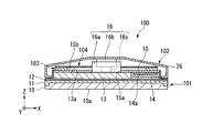
- FIG. 2 is a diagram showing a configuration along the section AA in FIG.
- the main body unit 101 includes a display panel 10, a first base unit 11, a second base unit 12, a battery 13, a first substrate 14, a bottom cover 15, and a vibration unit 16.
- the main body 101 is assembled in a state where these components are stacked.
- an XYZ orthogonal coordinate system is used to describe the configuration of the electronic device 100.
- the stacking direction of the components of the main body 101 is defined as the Z direction.
- a plane orthogonal to the Z direction is defined as an XY plane, and directions orthogonal to the XY plane are defined as an X direction and a Y direction, respectively.
- the display panel 10 is formed in a rectangle when viewed in the Z direction.
- the display panel 10 has a display surface 10a on the ⁇ Z side surface. Images such as still images and moving images are displayed on the display surface 10a.
- a liquid crystal display panel or an organic EL panel is used as the display panel 10.
- a touch panel mechanism (not shown) may be provided on the display surface 10a of the display panel 10.
- the first base unit 11 holds the display panel 10.
- the first base portion 11 is formed in a rectangular frame shape when viewed in the Z direction.
- the 1st base part 11 is formed so that the side part of the display panel 10 and the peripheral part of the display surface 10a may be enclosed.
- the second base portion 12 is disposed on the + Z side of the first base portion 11. A part of the second base portion 12 is supported by the first base portion 11.
- the battery 13 is formed in a rectangular plate shape.
- the battery 13 supplies power to each part of the electronic device 100.
- the battery 13 is connected to each part of the electronic device 100 via a wiring (not shown).
- the surface 13a on the + Z side of the battery 13 is formed flat.
- the first substrate 14 is arranged so as to leave a space where the battery 13 is arranged.
- the first substrate 14 is supported by the second base portion 12.
- a control circuit 14 a is formed on the first substrate 14. In the electronic device 100, each unit is electrically controlled by the control circuit 14a.
- the bottom cover 15 is formed in a rectangular plate shape.
- the bottom cover 15 is disposed on the + Z side of the battery 13 and the first substrate 14 and is disposed so as to cover the battery 13 and the first substrate 14.
- a circular opening 15 a is formed at the center of the bottom cover 15. A part of the surface 13a on the + Z side of the battery 13 is exposed in the opening 15a.
- the vibration unit 16 includes a stator 16a, a mover 16b, and a drive source 16c.
- the stator 16a is formed in a cylindrical shape and accommodates the mover 16b and the drive source 16c.
- the stator 16 a is disposed in the opening 15 a of the bottom cover 15.
- the mover 16b is provided to be movable in the Z direction.
- the drive source 16c is connected to the mover 16b and moves the mover 16b in the Z direction.
- a voice coil motor is used as the drive source 16c.
- the operation of the drive source 16c is performed by the control circuit 14a provided on the first substrate 14 described above.
- the vibration part 16 has a configuration in which the moving element 16b vibrates in the Z direction when the driving source 16c reciprocates the moving element 16b in the Z direction.
- the control circuit 14a can adjust the reciprocating frequency of the moving element 16b at any time. By adjusting the reciprocating frequency of the moving element 16b, the frequency of vibration generated in the vibration unit 16 can be set to a desired value. For example, the vibration unit 16 can set the vibration frequency between 90 Hz and 120 Hz.
- the movable part 102 has a housing 26.
- the casing 26 is formed so as to cover a part of the + Z side surface of the main body 101.
- the casing 26 is connected to the moving element 16 b of the vibration unit 16. Therefore, the casing 26 is provided so as to be movable in the Z direction integrally with the mover 16b.
- the vibration of the mover 16b is transmitted to the casing 26, and the casing 26 vibrates in the Z direction.
- the plurality of resonators 103 are arranged on the surface 15b on the + Z side of the bottom cover 15.
- the plurality of resonators 103 are configured to resonate with respect to vibrations having a predetermined frequency set.
- the plurality of resonators 103 are sandwiched between the bottom cover 15 and the transmission unit 104 in the Z direction.
- the transmission unit 104 transmits the vibration of the vibration unit 16 to the plurality of resonators 103.
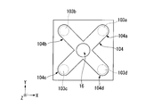
- FIG. 3 is a plan view showing a configuration when the electronic device 100 is viewed from the + Z side.
- the casing 26 is not shown for easy identification of the plurality of resonators 103 and the transmission unit 104.
- each resonator 103 is arranged one by one at four corners of the main body 101 in plan view.
- the vibration unit 16 is disposed at the center of gravity of the main body 101 in a plan view, that is, at the center of the main body 101.
- the transmission unit 104 is formed in a cross shape in plan view.
- the plurality of resonators 103 are respectively connected to four end portions 104a to 104d of the transmission unit 104 (resonators 103a to 103d).
- the resonators 103a to 103d are arranged so that the distances from the vibrating portion 16 are equal to each other.
- the resonators 103a to 103d are set so that the resonating frequencies are different.
- the resonators 103a to 103d have different resonance frequencies.
- the resonance frequency of the resonator 103a is set to 90 Hz
- the resonance frequency of the resonator 103b is set to 100 Hz
- the resonance frequency of the resonator 103c is set to 110 Hz
- the resonance frequency of the resonator 103d Is set to 120 Hz.
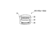
- FIG. 4 is a perspective view showing the configuration of one resonator 103.
- the resonator 103 (103a to 103d) includes a container 31, a first spring member 32, a weight 33, and a second spring member.
- the spring constants of the first spring member 32 and the second spring member 34 and the mass of the weight 33 are set so that the resonance frequency becomes the above frequency.
- the mover 16b moves in the ⁇ Z direction from the state shown in FIG. 5 and returns to the state shown in FIG. 2, the casing 26 moves in the ⁇ Z direction as the mover 16b moves. Also in this case, a relative movement has been performed between the main body 101 and the movable part 102. Thus, the movable part 102 vibrates with respect to the main-body part 101 by the movement (vibration) of the slider 16b.
- the vibration generated in the vibration part 16 by this movement is transmitted to the resonators 103a to 103d via the stator 16a and the transmission part 104.
- the vibration frequency of the vibration unit 16 is 90 Hz
- the resonator 103a having a resonance frequency of 90 Hz resonates.
- the other resonators 103b to 103d do not resonate.
- produces locally in the corner
- the resonator 103b having a resonance frequency of 100 Hz resonates.
- the other resonators 103a, 103c, and 103d do not resonate.
- produces locally in the corner
- the resonator 103d having a resonance frequency of 120 Hz resonates.
- the other resonators 103a to 103c do not resonate. For this reason, vibration is locally generated at the corner where the resonator 103d is arranged among the four corners of the main body 101.
- the vibration frequency of the vibration part 16 is changed to, for example, 90 Hz, 100 Hz, 110 Hz, and 120 Hz.
- the part of the main body part 101 where the vibration is generated is moved counterclockwise.
- the portion that generates vibration locally can be moved to a desired position.
- the main body 101 that accommodates the control circuit 14a, the vibration unit 16 that is provided in the main body 101 and vibrates in a predetermined direction and the frequency of vibration is variable, and the main body 101 Of these, a plurality of resonators 103 that are provided in different portions and resonate with respect to vibrations having different frequencies, and a transmission unit 104 that transmits the vibration of the vibration unit 16 to the plurality of resonators 103 are provided.
- a plurality of resonators 103 that are provided in different portions and resonate with respect to vibrations having different frequencies
- a transmission unit 104 that transmits the vibration of the vibration unit 16 to the plurality of resonators 103 are provided.
- the technical scope of the present invention is not limited to the above-described embodiment, and appropriate modifications can be made without departing from the spirit of the present invention.
- the configuration in which the vibration unit 16 is connected to the central portion of the transmission unit 104 in a plan view has been described as an example.
- the configuration is not limited thereto.
- the vibration unit 16 may be connected to a position out of the center of the transmission unit 104. As a result, a greater variety of vibration states can be reproduced.
- the configuration in which the plurality of resonators 103 are arranged at positions where the distance from the vibration unit 16 is equal is described as an example, but the present invention is not limited to this.
- the resonators 103 may be arranged so that the distance from the vibration unit 16 is different for each resonator 103. Further, some of the resonators 103 may be arranged so that the distance from the vibration unit 16 is equal.
- the transmission unit 104 is described as a cross-shaped configuration in plan view, but the present invention is not limited to this.
- the transmission unit 104 may be configured to have a circular shape, a triangular shape, a polygonal shape such as a quadrangular shape, or another planar shape in plan view.
- the configuration in which the main body 101 is formed in a rectangular shape in plan view has been described as an example.
- the present invention is not limited to this.
- the main body 101 may have a configuration in which the main body 101 is formed in a circular shape in plan view, or a configuration having another planar shape such as a triangle or a cross.
- the configuration in which the plurality of resonators 103a to 103d are arranged one by one at the four corners of the main body 101 has been described as an example.
- the present invention is not limited to this.
- a configuration may be adopted in which a plurality of pieces are arranged at four corners.
- the resonator 103 is not limited to the corner portion of the main body 101 and may be provided in other portions.
- the electronic device 100 can be applied to the present invention even if the movable unit 102 is not provided.
Landscapes
- Engineering & Computer Science (AREA)
- Mechanical Engineering (AREA)
- Physics & Mathematics (AREA)
- Electromagnetism (AREA)
- Apparatuses For Generation Of Mechanical Vibrations (AREA)
- Telephone Set Structure (AREA)
Abstract
電子機器は、電子回路を収容する本体部と、前記本体部に設けられ、所定方向に振動し、振動の周波数が可変である振動部と、前記本体部のうちそれぞれ異なる部分に設けられ、それぞれが異なる周波数の振動に対して共振する複数の共振子と、前記振動部の振動を複数の前記共振子に伝達する伝達部とを備える。
Description
本発明は、電子機器に関する。
本願は、2012年3月5日に出願された特願2012-48275号に基づき優先権を主張し、その内容をここに援用する。
本願は、2012年3月5日に出願された特願2012-48275号に基づき優先権を主張し、その内容をここに援用する。
携帯電話や携帯情報端末などの電子機器として、例えば特許文献1が知られている。特許文献1に示すような電子機器においては、ユーザに振動を検知させる構成が用いられる場合がある。
このような振動を発生させる振動発生装置として、例えば振動モーターが知られている。振動モーターとしては、例えば円筒型の回転子の先端に錘をつけ、モーターの回転により振動を発生させている構成が知られている。
このような振動を発生させる振動発生装置として、例えば振動モーターが知られている。振動モーターとしては、例えば円筒型の回転子の先端に錘をつけ、モーターの回転により振動を発生させている構成が知られている。
しかしながら、従来の振動モーターでは、幅広い振動状態を再現することが困難であった。
本発明の態様は、幅広い振動状態を再現することが可能な電子機器を提供することを目的とする。
本発明の第一の態様に従えば、電子回路を収容する本体部と、前記本体部に設けられ、所定方向に振動し、振動の周波数が可変である振動部と、前記本体部のうちそれぞれ異なる部分に設けられ、それぞれが異なる周波数の振動に対して共振する複数の共振子と、前記振動部の振動を複数の前記共振子に伝達する伝達部とを備える。
本発明の態様によれば、幅広い振動状態を再現することが可能な電子機器を提供することができる。
以下、図面を参照して、本発明の実施の形態を説明する。
図1は、本発明の実施の形態に係る電子機器100の構成を示す斜視図である。
図1に示すように、電子機器100は、矩形の板状に形成された本体部101と、本体部101に振動部16を介して接続された可動部102とを有する。また、本体部101には、複数の共振子103と、伝達部104とが設けられている。
図1は、本発明の実施の形態に係る電子機器100の構成を示す斜視図である。
図1に示すように、電子機器100は、矩形の板状に形成された本体部101と、本体部101に振動部16を介して接続された可動部102とを有する。また、本体部101には、複数の共振子103と、伝達部104とが設けられている。
図2は、図1におけるA-A断面に沿った構成を示す図である。
図2に示すように、本体部101は、表示パネル10、第一ベース部11、第二ベース部12、バッテリー13、第一基板14、ボトムカバー15及び振動部16を有している。本体部101は、これらの各構成要素が積層された状態で組み立てられている。
図2に示すように、本体部101は、表示パネル10、第一ベース部11、第二ベース部12、バッテリー13、第一基板14、ボトムカバー15及び振動部16を有している。本体部101は、これらの各構成要素が積層された状態で組み立てられている。
以下、本実施形態において、電子機器100の構成を説明するに当たり、XYZ直交座標系を用いる。XYZ直交座標系において、本体部101の各構成要素の積層方向をZ方向とする。また、Z方向に直交する平面をXY平面とし、XY平面において直交する方向をそれぞれX方向及びY方向とする。
表示パネル10は、Z方向視で矩形に形成されている。表示パネル10は、-Z側の面が表示面10aとなっている。表示面10aには、静止画や動画などの画像が表示される。表示パネル10としては、例えば液晶表示パネルや、有機ELパネルなどが用いられる。表示パネル10の表示面10a上に、不図示のタッチパネル機構を設ける構成としても構わない。
第一ベース部11は、表示パネル10を保持する。第一ベース部11は、Z方向視で矩形の枠状に形成されている。第一ベース部11は、表示パネル10の側部及び表示面10aの周縁部を囲うように形成されている。第二ベース部12は、第一ベース部11の+Z側に配置されている。第二ベース部12の一部は、第一ベース部11に支持されている。
バッテリー13は、外形が矩形の板状に形成されている。バッテリー13は、電子機器100の各部に電力を供給する。バッテリー13は、不図示の配線を介して電子機器100の各部に接続されている。バッテリー13の+Z側の面13aは、平坦に形成されている。
第一基板14は、バッテリー13が配置されるスペースを空けるように配置されている。第一基板14は、第二ベース部12に支持されている。第一基板14には、制御回路14aが形成されている。電子機器100は、制御回路14aによって各部が電気的に制御される構成となっている。
ボトムカバー15は、矩形板状に形成されている。ボトムカバー15は、バッテリー13及び第一基板14の+Z側に配置され、バッテリー13及び第一基板14を被うように配置されている。ボトムカバー15の中央部には、円形の開口部15aが形成されている。開口部15aには、バッテリー13の+Z側の面13aが一部露出している。
振動部16は、固定子16a、移動子16b及び駆動源16cを有する。固定子16aは、円筒状に形成されており、移動子16b及び駆動源16cを収容する。固定子16aは、ボトムカバー15の開口部15a内に配置されている。
移動子16bは、Z方向に移動可能に設けられている。駆動源16cは、移動子16bに接続されており、移動子16bをZ方向に移動させる。駆動源16cとしては、ボイスコイルモーターが用いられている。
駆動源16cの動作は、上記の第一基板14に設けられた制御回路14aによって行われる。振動部16は、駆動源16cが移動子16bをZ方向に往復移動させることにより、移動子16bがZ方向に振動する構成である。
なお、制御回路14aは、移動子16bの往復の周波数を随時調整することができる。移動子16bの往復の周波数を調整することにより、振動部16において発生する振動の周波数を所望の値に設定することができる。例えば、振動部16において、90Hz~120Hzの間で振動の周波数を設定可能である。
駆動源16cの動作は、上記の第一基板14に設けられた制御回路14aによって行われる。振動部16は、駆動源16cが移動子16bをZ方向に往復移動させることにより、移動子16bがZ方向に振動する構成である。
なお、制御回路14aは、移動子16bの往復の周波数を随時調整することができる。移動子16bの往復の周波数を調整することにより、振動部16において発生する振動の周波数を所望の値に設定することができる。例えば、振動部16において、90Hz~120Hzの間で振動の周波数を設定可能である。
可動部102は、筐体26を有している。筐体26は、本体部101の+Z側の面の一部を覆うように形成されている。筐体26は、振動部16の移動子16bに接続されている。したがって、筐体26は、移動子16bと一体的にZ方向に移動可能に設けられている。
移動子16bがZ方向に振動することにより、移動子16bの振動が筐体26に伝達され、筐体26がZ方向に振動する。
移動子16bがZ方向に振動することにより、移動子16bの振動が筐体26に伝達され、筐体26がZ方向に振動する。
複数の共振子103は、ボトムカバー15の+Z側の面15b上に配置されている。複数の共振子103は、各々設定された所定の周波数の振動に対して共振するように構成されている。複数の共振子103は、Z方向においてボトムカバー15と伝達部104との間に挟まれている。伝達部104は、振動部16の振動を複数の共振子103に伝達する。
図3は、電子機器100を+Z側から見たときの構成を示す平面図である。但し、図3において、複数の共振子103及び伝達部104を判別しやすくするため、筐体26の図示を省略している。
図3に示すように、各共振子103は、平面視において本体部101の4つの角部に1つずつ配置されている。振動部16は、平面視において本体部101の重心位置、すなわち本体部101の中心部に配置されている。
図3に示すように、各共振子103は、平面視において本体部101の4つの角部に1つずつ配置されている。振動部16は、平面視において本体部101の重心位置、すなわち本体部101の中心部に配置されている。
伝達部104は、平面視において十字型に形成されている。複数の共振子103は、伝達部104のうち4つの端部104a~104dにそれぞれ接続されている(共振子103a~共振子103d)。共振子103a~共振子103dは、それぞれ振動部16からの距離が等しくなるように配置されている。
なお、共振子103a~共振子103dは、それぞれ共振する周波数が異なるように設定されている。共振子103a~共振子103dは、互いに異なる共振周波数を有する。
例えば、共振子103aの共振周波数は90Hzに設定されており、共振子103bの共振周波数は100Hzに設定されており、共振子103cの共振周波数は110Hzに設定されており、共振子103dの共振周波数は120Hzに設定されている。
例えば、共振子103aの共振周波数は90Hzに設定されており、共振子103bの共振周波数は100Hzに設定されており、共振子103cの共振周波数は110Hzに設定されており、共振子103dの共振周波数は120Hzに設定されている。
図4は、1個の共振子103の構成を示す斜視図である。
図4に示すように、共振子103(103a~103d)は、容器31、第一バネ部材32、錘33及び第二バネ部材34を有している。共振子103a~共振子103dのそれぞれにおいて、共振周波数が上記周波数となるように第一バネ部材32及び第二バネ部材34のバネ定数や錘33の質量が設定されている。
図4に示すように、共振子103(103a~103d)は、容器31、第一バネ部材32、錘33及び第二バネ部材34を有している。共振子103a~共振子103dのそれぞれにおいて、共振周波数が上記周波数となるように第一バネ部材32及び第二バネ部材34のバネ定数や錘33の質量が設定されている。
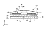
この構成において、例えば移動子16bが図2に示す状態から+Z方向に移動する場合には、図5に示すように、筐体26は移動子16bの移動に伴って+Z方向へ移動する。
したがって、本体部101と可動部102との間が広がることになり、本体部101と可動部102との間で相対的な移動が行われたことになる。
したがって、本体部101と可動部102との間が広がることになり、本体部101と可動部102との間で相対的な移動が行われたことになる。
また、図5に示す状態から移動子16bが-Z方向に移動し、図2に示す状態に戻ると、筐体26は移動子16bの移動に伴って-Z方向へ移動する。この場合にも、本体部101と可動部102との間で相対的な移動が行われたことになる。このように、移動子16bの移動(振動)によって可動部102が本体部101に対して振動する。
移動子16bが移動する場合、この移動により振動部16において発生する振動は、固定子16a及び伝達部104を介して、各共振子103a~103dに伝達される。
ここで、振動部16の振動の周波数が90Hzである場合、共振周波数が90Hzである共振子103aが共振する。なお、このとき他の共振子103b~103dは共振しない。このため、本体部101の4つの角部のうち共振子103aが配置された角部において局所的に振動が発生する。
ここで、振動部16の振動の周波数が90Hzである場合、共振周波数が90Hzである共振子103aが共振する。なお、このとき他の共振子103b~103dは共振しない。このため、本体部101の4つの角部のうち共振子103aが配置された角部において局所的に振動が発生する。
また、振動部16の振動の周波数が100Hzである場合、共振周波数が100Hzである共振子103bが共振する。なお、他の共振子103a、103c、103dは共振しない。このため、本体部101の4つの角部のうち共振子103bが配置された角部において局所的に振動が発生する。
同様に、振動部16の振動の周波数が110Hzである場合、共振周波数が110Hzである共振子103cが共振する。なお、他の共振子103a、103b、103dは共振しない。このため、本体部101の4つの角部のうち共振子103cが配置された角部において局所的に振動が発生する。
同様に、振動部16の振動の周波数が120Hzである場合、共振周波数が120Hzである共振子103dが共振する。なお、他の共振子103a~103cは共振しない。このため、本体部101の4つの角部のうち共振子103dが配置された角部において局所的に振動が発生する。
更には、振動部16の振動の周波数を、例えば90Hz、100Hz、110Hz、120Hzと周期的に変化させることにより、本体部101のうち局所的に振動が発生する部分を反時計回りに移動させることができる。周波数の大きさと順序を適宜組み合わせることで、局所的に振動を発生させる部分を所望の位置に移動させることができる。
以上のように、本実施形態によれば、制御回路14aを収容する本体部101と、本体部101に設けられ所定方向に振動し振動の周波数が可変である振動部16と、本体部101のうちそれぞれ異なる部分に設けられ、それぞれが異なる周波数の振動に対して共振する複数の共振子103と、振動部16の振動を複数の共振子103に伝達する伝達部104とを備える。
これにより、振動部16において発生させる振動を、各共振子103の共振周波数に対応させることで、各共振子103を個別に共振させることができ、本体部101において局所的に振動を発生させることができる。これにより、幅広い振動状態を再現することが可能となる。
これにより、振動部16において発生させる振動を、各共振子103の共振周波数に対応させることで、各共振子103を個別に共振させることができ、本体部101において局所的に振動を発生させることができる。これにより、幅広い振動状態を再現することが可能となる。
本発明の技術範囲は上記実施形態に限定されるものではなく、本発明の趣旨を逸脱しない範囲で適宜変更を加えることができる。
例えば、上記実施形態においては、振動部16が平面視において伝達部104の中央部に接続された構成を例に挙げて説明したが、これに限られることは無い。例えば振動部16が伝達部104のうち中央部から外れた位置に接続されていても構わない。これにより、一層多様な振動状態を再現することができる。
例えば、上記実施形態においては、振動部16が平面視において伝達部104の中央部に接続された構成を例に挙げて説明したが、これに限られることは無い。例えば振動部16が伝達部104のうち中央部から外れた位置に接続されていても構わない。これにより、一層多様な振動状態を再現することができる。
また、上記実施形態では、振動部16からの距離が等しくなる位置に複数の共振子103が配置された構成を例に挙げて説明したが、これに限られることは無い。例えば、共振子103ごとに振動部16からの距離が異なるように配置されていても構わない。また、一部の共振子103について振動部16からの距離が等しくなるように配置されていても構わない。
また、上記実施形態においては、伝達部104が平面視で十字型に形成された構成を例に挙げて説明したが、これに限られることは無い。例えば伝達部104が平面視において円形や三角形、四角形などの多角形、又は他の平面形状を有する構成であっても構わない。
また、上記実施形態においては、本体部101が平面視で矩形に形成された構成を例に挙げて説明したが、これに限られることは無い。例えば本体部101が平面視において円形に形成された構成や三角形、十字型など他の平面形状を有する構成であっても構わない。
また、上記実施形態においては、複数の共振子103a~103dが本体部101の4つの角部に1つずつ配置された構成を例に挙げて説明したが、これに限られることは無く、例えば4つの角部に複数個ずつ配置された構成であっても構わない。また、本体部101の角部に限られず、他の部位に共振子103が設けられていても構わない。
また、電子機器100において、可動部102が設けられていない構成であっても、本発明の適用は可能である。
16…振動部 16a…固定子 16b…移動子 16c…駆動源 26…筐体 31…容器 32…第一バネ部材 33…錘 34…第二バネ部材 100…電子機器 101…本体部 102…可動部 103…共振子 103a~103d…共振子 104…伝達部 104a~104d…端部。
Claims (7)
- 電子回路を収容する本体部と、
前記本体部に設けられ、所定方向に振動し、振動の周波数が可変である振動部と、
前記本体部のうちそれぞれ異なる部分に設けられ、それぞれが異なる周波数の振動に対して共振する複数の共振子と、
前記振動部の振動を複数の前記共振子に伝達する伝達部と
を備える電子機器。 - 前記振動部を介して前記本体部に接続され、前記振動部の振動によって前記本体部に対して相対的に振動する可動部
を更に備える請求項1に記載の電子機器。 - 前記本体部は、平面視において角部を有する形状に形成され、
複数の前記共振子は、前記本体部のうち前記角部に設けられている
請求項1又は請求項2に記載の電子機器。 - 前記本体部は、平面視において矩形に形成され、
複数の前記共振子は、前記本体部のうち4つの角部に1つずつ設けられている
請求項1から請求項3のうちいずれか一項に記載の電子機器。 - 前記振動部は、平面視において前記本体部の重心位置に配置されている
請求項1から請求項4のうちいずれか一項に記載の電子機器。 - 前記伝達部は、平面視において十字型に形成されており、
複数の前記共振子は、前記伝達部のうち4つの端部にそれぞれ接続されている
請求項1から請求項5のうちいずれか一項に記載の電子機器。 - 前記振動部は、平面視において前記伝達部の中央部に接続されており、
複数の前記共振子は、前記振動部からの距離が等しくなる位置に配置されている
請求項6に記載の電子機器。
Priority Applications (2)
| Application Number | Priority Date | Filing Date | Title |
|---|---|---|---|
| JP2014503830A JP5954405B2 (ja) | 2012-03-05 | 2013-03-04 | 電子機器 |
| US14/474,434 US9527110B2 (en) | 2012-03-05 | 2014-09-02 | Electronic apparatus |
Applications Claiming Priority (2)
| Application Number | Priority Date | Filing Date | Title |
|---|---|---|---|
| JP2012-048275 | 2012-03-05 | ||
| JP2012048275 | 2012-03-05 |
Related Child Applications (1)
| Application Number | Title | Priority Date | Filing Date |
|---|---|---|---|
| US14/474,434 Continuation US9527110B2 (en) | 2012-03-05 | 2014-09-02 | Electronic apparatus |
Publications (1)
| Publication Number | Publication Date |
|---|---|
| WO2013133199A1 true WO2013133199A1 (ja) | 2013-09-12 |
Family
ID=49116676
Family Applications (1)
| Application Number | Title | Priority Date | Filing Date |
|---|---|---|---|
| PCT/JP2013/055807 Ceased WO2013133199A1 (ja) | 2012-03-05 | 2013-03-04 | 電子機器 |
Country Status (3)
| Country | Link |
|---|---|
| US (1) | US9527110B2 (ja) |
| JP (1) | JP5954405B2 (ja) |
| WO (1) | WO2013133199A1 (ja) |
Cited By (3)
| Publication number | Priority date | Publication date | Assignee | Title |
|---|---|---|---|---|
| JP2015116508A (ja) * | 2013-12-16 | 2015-06-25 | 富士通株式会社 | 筐体の振動装置及び振動装置を備える電子機器 |
| WO2018126615A1 (zh) * | 2017-01-04 | 2018-07-12 | 歌尔股份有限公司 | 一种振动模组以及振动模块 |
| WO2018189914A1 (ja) * | 2017-04-14 | 2018-10-18 | 富士通株式会社 | 触感提供装置、及び、シミュレーションシステム |
Families Citing this family (2)
| Publication number | Priority date | Publication date | Assignee | Title |
|---|---|---|---|---|
| JP7155805B2 (ja) * | 2018-09-21 | 2022-10-19 | コニカミノルタ株式会社 | 入力装置および画像形成装置 |
| US10529198B1 (en) * | 2018-12-27 | 2020-01-07 | Immersion Corporation | Tunable resonance haptic device |
Citations (3)
| Publication number | Priority date | Publication date | Assignee | Title |
|---|---|---|---|---|
| JPH02127696A (ja) * | 1988-11-08 | 1990-05-16 | Murata Mfg Co Ltd | 振動アラーム装置 |
| JPH0635476A (ja) * | 1992-07-21 | 1994-02-10 | Murata Mfg Co Ltd | 振動装置 |
| JPH0975847A (ja) * | 1995-09-13 | 1997-03-25 | Toshiba Corp | 磁歪式振動子 |
Family Cites Families (3)
| Publication number | Priority date | Publication date | Assignee | Title |
|---|---|---|---|---|
| GB2336433B (en) * | 1998-04-14 | 2002-02-06 | Mitutoyo Corp | Touch signal probe |
| US7681433B2 (en) * | 2005-05-30 | 2010-03-23 | National Institute Of Advanced Industrial Science And Technology | Detection sensor and resonator |
| JP2010086089A (ja) | 2008-09-29 | 2010-04-15 | Brother Ind Ltd | 携帯型表示端末及びプログラム |
-
2013
- 2013-03-04 JP JP2014503830A patent/JP5954405B2/ja not_active Expired - Fee Related
- 2013-03-04 WO PCT/JP2013/055807 patent/WO2013133199A1/ja not_active Ceased
-
2014
- 2014-09-02 US US14/474,434 patent/US9527110B2/en active Active
Patent Citations (3)
| Publication number | Priority date | Publication date | Assignee | Title |
|---|---|---|---|---|
| JPH02127696A (ja) * | 1988-11-08 | 1990-05-16 | Murata Mfg Co Ltd | 振動アラーム装置 |
| JPH0635476A (ja) * | 1992-07-21 | 1994-02-10 | Murata Mfg Co Ltd | 振動装置 |
| JPH0975847A (ja) * | 1995-09-13 | 1997-03-25 | Toshiba Corp | 磁歪式振動子 |
Cited By (4)
| Publication number | Priority date | Publication date | Assignee | Title |
|---|---|---|---|---|
| JP2015116508A (ja) * | 2013-12-16 | 2015-06-25 | 富士通株式会社 | 筐体の振動装置及び振動装置を備える電子機器 |
| WO2018126615A1 (zh) * | 2017-01-04 | 2018-07-12 | 歌尔股份有限公司 | 一种振动模组以及振动模块 |
| WO2018189914A1 (ja) * | 2017-04-14 | 2018-10-18 | 富士通株式会社 | 触感提供装置、及び、シミュレーションシステム |
| JPWO2018189914A1 (ja) * | 2017-04-14 | 2020-02-20 | 富士通株式会社 | 触感提供装置、及び、シミュレーションシステム |
Also Published As
| Publication number | Publication date |
|---|---|
| US20150076931A1 (en) | 2015-03-19 |
| JP5954405B2 (ja) | 2016-07-20 |
| US9527110B2 (en) | 2016-12-27 |
| JPWO2013133199A1 (ja) | 2015-07-30 |
Similar Documents
| Publication | Publication Date | Title |
|---|---|---|
| US9859780B2 (en) | Vibration motor | |
| US10864552B2 (en) | Pseudo force sense generation apparatus | |
| US10038360B2 (en) | Vibration motor | |
| JP5954405B2 (ja) | 電子機器 | |
| CN107534375B (zh) | 线性振动马达 | |
| JP6517649B2 (ja) | リニア振動モータ | |
| JP6591248B2 (ja) | リニア振動モータ | |
| WO2016017586A1 (ja) | リニア振動モータ | |
| KR101333794B1 (ko) | 진동 모듈 및 이를 이용한 햅틱 장치 | |
| US20170033662A1 (en) | Vibration Motor | |
| JP6663762B2 (ja) | リニア振動モータ | |
| CN207746087U (zh) | 振动致动器和便携式信息终端 | |
| US9724731B2 (en) | Electronic device with first and second vibration portions | |
| JP6396261B2 (ja) | リニア振動モータ | |
| WO2016084807A1 (ja) | リニア振動モータ | |
| JP6378127B2 (ja) | リニア振動モータ | |
| JP2018001108A (ja) | リニア振動モータ | |
| JP6479557B2 (ja) | リニア振動モータ | |
| JP2019193511A (ja) | リニア振動モータ及び電子機器 | |
| JP2013183441A (ja) | 電子機器 | |
| JP2013233009A (ja) | ボイスコイルモーター及び電子機器 | |
| JP2013187563A (ja) | 電子機器 | |
| WO2013015324A1 (ja) | 電子機器 |
Legal Events
| Date | Code | Title | Description |
|---|---|---|---|
| 121 | Ep: the epo has been informed by wipo that ep was designated in this application |
Ref document number: 13757700 Country of ref document: EP Kind code of ref document: A1 |
|
| ENP | Entry into the national phase |
Ref document number: 2014503830 Country of ref document: JP Kind code of ref document: A |
|
| NENP | Non-entry into the national phase |
Ref country code: DE |
|
| 122 | Ep: pct application non-entry in european phase |
Ref document number: 13757700 Country of ref document: EP Kind code of ref document: A1 |