WO2013129194A1 - Support mobile compact/léger et dispositif de thérapie par faisceau de particules l'utilisant - Google Patents
Support mobile compact/léger et dispositif de thérapie par faisceau de particules l'utilisant Download PDFInfo
- Publication number
- WO2013129194A1 WO2013129194A1 PCT/JP2013/054068 JP2013054068W WO2013129194A1 WO 2013129194 A1 WO2013129194 A1 WO 2013129194A1 JP 2013054068 W JP2013054068 W JP 2013054068W WO 2013129194 A1 WO2013129194 A1 WO 2013129194A1
- Authority
- WO
- WIPO (PCT)
- Prior art keywords
- scanning
- electromagnet
- gantry
- electromagnets
- deflection
- Prior art date
Links
Images


Classifications
-
- A—HUMAN NECESSITIES
- A61—MEDICAL OR VETERINARY SCIENCE; HYGIENE
- A61N—ELECTROTHERAPY; MAGNETOTHERAPY; RADIATION THERAPY; ULTRASOUND THERAPY
- A61N5/00—Radiation therapy
- A61N5/10—X-ray therapy; Gamma-ray therapy; Particle-irradiation therapy
- A61N5/1077—Beam delivery systems
- A61N5/1081—Rotating beam systems with a specific mechanical construction, e.g. gantries
-
- A—HUMAN NECESSITIES
- A61—MEDICAL OR VETERINARY SCIENCE; HYGIENE
- A61N—ELECTROTHERAPY; MAGNETOTHERAPY; RADIATION THERAPY; ULTRASOUND THERAPY
- A61N5/00—Radiation therapy
- A61N5/10—X-ray therapy; Gamma-ray therapy; Particle-irradiation therapy
- A61N5/1077—Beam delivery systems
-
- A—HUMAN NECESSITIES
- A61—MEDICAL OR VETERINARY SCIENCE; HYGIENE
- A61N—ELECTROTHERAPY; MAGNETOTHERAPY; RADIATION THERAPY; ULTRASOUND THERAPY
- A61N5/00—Radiation therapy
- A61N5/10—X-ray therapy; Gamma-ray therapy; Particle-irradiation therapy
- A61N5/1042—X-ray therapy; Gamma-ray therapy; Particle-irradiation therapy with spatial modulation of the radiation beam within the treatment head
- A61N5/1043—Scanning the radiation beam, e.g. spot scanning or raster scanning
-
- A—HUMAN NECESSITIES
- A61—MEDICAL OR VETERINARY SCIENCE; HYGIENE
- A61N—ELECTROTHERAPY; MAGNETOTHERAPY; RADIATION THERAPY; ULTRASOUND THERAPY
- A61N5/00—Radiation therapy
- A61N5/10—X-ray therapy; Gamma-ray therapy; Particle-irradiation therapy
- A61N5/1048—Monitoring, verifying, controlling systems and methods
- A61N5/1064—Monitoring, verifying, controlling systems and methods for adjusting radiation treatment in response to monitoring
- A61N5/1065—Beam adjustment
-
- A—HUMAN NECESSITIES
- A61—MEDICAL OR VETERINARY SCIENCE; HYGIENE
- A61N—ELECTROTHERAPY; MAGNETOTHERAPY; RADIATION THERAPY; ULTRASOUND THERAPY
- A61N5/00—Radiation therapy
- A61N5/10—X-ray therapy; Gamma-ray therapy; Particle-irradiation therapy
- A61N2005/1085—X-ray therapy; Gamma-ray therapy; Particle-irradiation therapy characterised by the type of particles applied to the patient
- A61N2005/1087—Ions; Protons
-
- F—MECHANICAL ENGINEERING; LIGHTING; HEATING; WEAPONS; BLASTING
- F04—POSITIVE - DISPLACEMENT MACHINES FOR LIQUIDS; PUMPS FOR LIQUIDS OR ELASTIC FLUIDS
- F04C—ROTARY-PISTON, OR OSCILLATING-PISTON, POSITIVE-DISPLACEMENT MACHINES FOR LIQUIDS; ROTARY-PISTON, OR OSCILLATING-PISTON, POSITIVE-DISPLACEMENT PUMPS
- F04C2270/00—Control; Monitoring or safety arrangements
- F04C2270/04—Force
- F04C2270/041—Controlled or regulated
-
- G—PHYSICS
- G21—NUCLEAR PHYSICS; NUCLEAR ENGINEERING
- G21K—TECHNIQUES FOR HANDLING PARTICLES OR IONISING RADIATION NOT OTHERWISE PROVIDED FOR; IRRADIATION DEVICES; GAMMA RAY OR X-RAY MICROSCOPES
- G21K1/00—Arrangements for handling particles or ionising radiation, e.g. focusing or moderating
- G21K1/08—Deviation, concentration or focusing of the beam by electric or magnetic means
- G21K1/093—Deviation, concentration or focusing of the beam by electric or magnetic means by magnetic means
Definitions
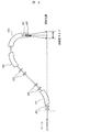
- FIG. 3 shows the rotating gantry of Comparative Example 1 that scans and irradiates the beam trajectory.
- the irradiation gantry includes deflection electromagnets 101, 102, and 103 that deflect the beam trajectory, a quadrupole electromagnet 201 that converges and diverges the beam, a horizontal scanning electromagnet 301 that scans the beam horizontally, and a vertical scanning electromagnet 401 that scans vertically. .
- the scanning electromagnets 301 and 401 are arranged on the downstream side of the final deflecting electromagnet 103, and scan the beam in accordance with the affected part (change the irradiation position of the beam by changing the excitation amount of the scanning magnet with time).
- the deflection electromagnet 103 is disposed between the horizontal scanning electromagnets 301 and 302. Since the displacement at the irradiation position is the superposition of the scanning electromagnets 301 and 302 as described above, it is possible to adjust the amount of displacement by each of the scanning electromagnets 301 and 302, and a comparative example configured with one scanning electromagnet. In the case of 1/2 of 2, the deflection angle of the upstream horizontal scanning electromagnet 301 can be suppressed to about half. This means that the orbital displacement in the deflection electromagnet 103 region can be suppressed to about half that of the comparative example, and the deflection electromagnet 103 can be reduced in size and weight. In other words, the deflection electromagnet can be reduced in size and weight while ensuring the necessary irradiation field size.
- the phase difference between the upstream horizontal scanning electromagnet 301 and the downstream horizontal scanning electromagnet 302 is the quadrupole electromagnet 201 disposed between the scanning electromagnets 301 and 302, the edge angle or the n value of the deflection electromagnet 103, or the dipole or quadrupole composite type. If necessary, the intensity of the quadrupole magnetic field component may be adjusted.
- downstream horizontal scanning electromagnet 302 and the downstream vertical scanning electromagnet 402 are disposed adjacent to each other, so that the amount of beam displacement at the positions of the downstream scanning electromagnets 302 and 402 can be reduced, and the magnetic pole width of the downstream scanning electromagnet. It is possible to suppress an increase in the magnetic pole spacing.
- the gantry of each embodiment described above includes a deflection electromagnet 103 that deflects the beam trajectory, horizontal scanning electromagnets 301 and 302 that are first scanning electromagnets that scan the beam trajectory in the horizontal direction that is the first direction,
- a gantry having a vertical scanning electromagnet 401, which is a second scanning electromagnet that scans the beam trajectory in the vertical direction that is the two directions, includes a plurality of horizontal scanning electromagnets 301 and 302, and the horizontal scanning electromagnets 301 and 302
- the deflection electromagnet 103 is disposed between the plurality of horizontal scanning electromagnets 301 and 302 so that the phase difference is a natural number multiple of 180 degrees. With such a configuration, it is possible to realize a gantry capable of forming a large irradiation field while suppressing an increase in the size of the magnet by using the superposition of the beam displacement by the plurality of first scanning electromagnets.
- the second deflecting electromagnet is further downstream of the horizontal scanning electromagnet 302 or the vertical scanning electromagnet 402 that is the downstream first scanning electromagnet in the beam trajectory.
- the deflection electromagnet 104 is provided, the distance from the deflection electromagnet 104 to the irradiation target can be shortened, so that the rotation radius of the gantry can be reduced and the gantry can be downsized.
- each scanning electromagnet There is no need to prepare a separate power supply. In addition, synchronization between the electromagnets can be easily achieved.
- the phase difference between the two scanning electromagnets 301 and 302 is a natural number multiple of 180 degrees, but is somewhat deviated from the natural number multiple of 180 degrees, that is, the phase difference is 180 n degrees ⁇ ⁇ . Even if ⁇ is not 0 degree, it is possible to obtain the same kind of effect (n is a natural number, and ⁇ is 0 or more). This point will be described with reference to FIGS.
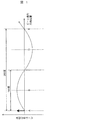
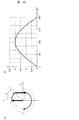
- FIG. 9 and 10 are diagrams showing the relationship between ⁇ and orbital displacement x when the phase difference between the gantry scanning electromagnets of each example is 180 n ° ⁇ ⁇ .
- FIG. 9 (a) simplifies the vibration of the beam with a single vibration model, and shows the beam position x at each position A to D and the angle dx / ds at each point on the x-dx / ds plane.
- Each embodiment corresponds to the case where the phase difference between the upstream first scanning electromagnet 301 and the downstream first scanning electromagnet 302 is 180 degrees as shown in FIG. In this case, the effect of increasing the absolute value of the trajectory displacement x at point D is the greatest.
- phase difference of 180 n ° ⁇ ⁇ between the horizontal scanning electromagnets 301 and 302 has been described. However, it is obvious that the same explanation can be applied to ⁇ regarding the phase difference of 180 n ° ⁇ ⁇ between the vertical electromagnets 401 and 402.
- the positions of the scanning electromagnets 301, 302, 401, and 402 have been described. However, this is described as meaning the center position of each scanning electromagnet in the direction along the beam flow direction.
- the phase difference between the upstream horizontal scanning magnet and the downstream horizontal scanning magnet must be less than 90 degrees. This is because if the phase difference is 90 degrees or more, the effect of downsizing the deflecting electromagnet cannot be obtained.
Landscapes
- Health & Medical Sciences (AREA)
- Engineering & Computer Science (AREA)
- Biomedical Technology (AREA)
- Pathology (AREA)
- Nuclear Medicine, Radiotherapy & Molecular Imaging (AREA)
- Radiology & Medical Imaging (AREA)
- Life Sciences & Earth Sciences (AREA)
- Animal Behavior & Ethology (AREA)
- General Health & Medical Sciences (AREA)
- Public Health (AREA)
- Veterinary Medicine (AREA)
- Radiation-Therapy Devices (AREA)
Abstract
L'invention concerne la configuration d'un dispositif et un agencement qui permettent de former un grand champ d'irradiation et qui sont appropriés pour réduire la taille et le poids d'un support mobile. Le support mobile de la présente invention est équipé d'un aimant déflecteur (103) qui dévie la trajectoire du faisceau, d'aimants (301, 302) de balayage à l'horizontale qui effectuent un premier balayage pour balayer la trajectoire du faisceau dans une direction horizontale représentant une première direction, et d'un aimant (401) de balayage à la verticale qui est un second aimant de balayage pour balayer la trajectoire du faisceau dans une direction verticale et qui représente une seconde direction. Une pluralité d'aimants de balayage de direction horizontale (301, 302) est réglée à 180n ° ± θ, θ étant disposé de manière à être 90° ou moins, et l'aimant déflecteur (103) est disposé entre la pluralité des aimants (301, 302) de balayage à l'horizontale.
Priority Applications (3)
| Application Number | Priority Date | Filing Date | Title |
|---|---|---|---|
| US14/373,939 US9084889B2 (en) | 2012-02-29 | 2013-02-20 | Compact and lightweight gantry and particle beam therapy device using the same |
| CN201380008041.9A CN104105527B (zh) | 2012-02-29 | 2013-02-20 | 小型、轻量架台和使用该架台的粒子线治疗装置 |
| EP13754905.1A EP2821102B1 (fr) | 2012-02-29 | 2013-02-20 | Support mobile compact/léger et dispositif de thérapie par faisceau de particules l'utilisant |
Applications Claiming Priority (2)
| Application Number | Priority Date | Filing Date | Title |
|---|---|---|---|
| JP2012042694A JP5872328B2 (ja) | 2012-02-29 | 2012-02-29 | 小型・軽量ガントリおよびこれを用いた粒子線治療装置 |
| JP2012-042694 | 2012-02-29 |
Publications (1)
| Publication Number | Publication Date |
|---|---|
| WO2013129194A1 true WO2013129194A1 (fr) | 2013-09-06 |
Family
ID=49082394
Family Applications (1)
| Application Number | Title | Priority Date | Filing Date |
|---|---|---|---|
| PCT/JP2013/054068 WO2013129194A1 (fr) | 2012-02-29 | 2013-02-20 | Support mobile compact/léger et dispositif de thérapie par faisceau de particules l'utilisant |
Country Status (5)
| Country | Link |
|---|---|
| US (1) | US9084889B2 (fr) |
| EP (1) | EP2821102B1 (fr) |
| JP (1) | JP5872328B2 (fr) |
| CN (1) | CN104105527B (fr) |
| WO (1) | WO2013129194A1 (fr) |
Families Citing this family (5)
| Publication number | Priority date | Publication date | Assignee | Title |
|---|---|---|---|---|
| JP6328487B2 (ja) * | 2014-05-20 | 2018-05-23 | 住友重機械工業株式会社 | 超伝導電磁石及び荷電粒子線治療装置 |
| DE102015106246A1 (de) * | 2015-04-23 | 2016-10-27 | Cryoelectra Gmbh | Strahlführungssystem, Teilchenstrahl-Therapieanlage und Verfahren |
| CN106139419B (zh) * | 2016-07-29 | 2022-10-28 | 中国原子能科学研究院 | 用于治疗肿瘤的旋转机架 |
| CN109982747B (zh) * | 2016-11-15 | 2021-04-02 | 株式会社东芝 | 粒子束输送装置、旋转机架和粒子束照射治疗系统 |
| WO2023146706A1 (fr) * | 2022-01-28 | 2023-08-03 | Mayo Foundation For Medical Education And Research | Système de thérapie par particules chargées utilisant des chambres couplées fluidiquement pour la sélection d'énergie |
Citations (4)
| Publication number | Priority date | Publication date | Assignee | Title |
|---|---|---|---|---|
| JPH10282300A (ja) * | 1997-02-07 | 1998-10-23 | Hitachi Ltd | 荷電粒子照射装置およびその運転方法 |
| JPH11142600A (ja) * | 1997-11-12 | 1999-05-28 | Mitsubishi Electric Corp | 荷電粒子線照射装置及び照射方法 |
| JP2004121654A (ja) | 2002-10-04 | 2004-04-22 | Hitachi Ltd | 医療用荷電粒子照射装置 |
| WO2010140236A1 (fr) * | 2009-06-03 | 2010-12-09 | 三菱電機株式会社 | Dispositif d'irradiation par faisceau de particules |
Family Cites Families (7)
| Publication number | Priority date | Publication date | Assignee | Title |
|---|---|---|---|---|
| US4870287A (en) * | 1988-03-03 | 1989-09-26 | Loma Linda University Medical Center | Multi-station proton beam therapy system |
| US6218675B1 (en) * | 1997-08-28 | 2001-04-17 | Hitachi, Ltd. | Charged particle beam irradiation apparatus |
| JP3779878B2 (ja) * | 2001-01-30 | 2006-05-31 | 株式会社日立製作所 | マルチリーフコリメータ |
| JP3801938B2 (ja) * | 2002-03-26 | 2006-07-26 | 株式会社日立製作所 | 粒子線治療システム及び荷電粒子ビーム軌道の調整方法 |
| JP3806723B2 (ja) * | 2004-11-16 | 2006-08-09 | 株式会社日立製作所 | 粒子線照射システム |
| DE102009055902B4 (de) * | 2009-11-26 | 2013-02-21 | Gsi Helmholtzzentrum Für Schwerionenforschung Gmbh | Verfahren und Vorrichtung zur Steuerung der Dosisapplikation bei der Bestrahlung |
| JP5791546B2 (ja) * | 2012-02-29 | 2015-10-07 | 株式会社日立製作所 | 放射線計測装置の較正方法及び粒子線治療装置 |
-
2012
- 2012-02-29 JP JP2012042694A patent/JP5872328B2/ja not_active Expired - Fee Related
-
2013
- 2013-02-20 CN CN201380008041.9A patent/CN104105527B/zh not_active Expired - Fee Related
- 2013-02-20 US US14/373,939 patent/US9084889B2/en not_active Expired - Fee Related
- 2013-02-20 EP EP13754905.1A patent/EP2821102B1/fr not_active Not-in-force
- 2013-02-20 WO PCT/JP2013/054068 patent/WO2013129194A1/fr active Application Filing
Patent Citations (4)
| Publication number | Priority date | Publication date | Assignee | Title |
|---|---|---|---|---|
| JPH10282300A (ja) * | 1997-02-07 | 1998-10-23 | Hitachi Ltd | 荷電粒子照射装置およびその運転方法 |
| JPH11142600A (ja) * | 1997-11-12 | 1999-05-28 | Mitsubishi Electric Corp | 荷電粒子線照射装置及び照射方法 |
| JP2004121654A (ja) | 2002-10-04 | 2004-04-22 | Hitachi Ltd | 医療用荷電粒子照射装置 |
| WO2010140236A1 (fr) * | 2009-06-03 | 2010-12-09 | 三菱電機株式会社 | Dispositif d'irradiation par faisceau de particules |
Non-Patent Citations (2)
| Title |
|---|
| "GANTRY STUDIES FOR THE PROPOSED HEAVY ION CANCER THERAPY FACILITY IN HEIDELBERG", PROCEEDINGS OF EPAC, 2000, pages 2551 - 2553 |
| See also references of EP2821102A4 |
Also Published As
| Publication number | Publication date |
|---|---|
| CN104105527B (zh) | 2016-09-21 |
| EP2821102B1 (fr) | 2017-11-08 |
| US9084889B2 (en) | 2015-07-21 |
| US20150083927A1 (en) | 2015-03-26 |
| JP5872328B2 (ja) | 2016-03-01 |
| EP2821102A1 (fr) | 2015-01-07 |
| CN104105527A (zh) | 2014-10-15 |
| JP2013176490A (ja) | 2013-09-09 |
| EP2821102A4 (fr) | 2015-11-04 |
Similar Documents
| Publication | Publication Date | Title |
|---|---|---|
| WO2013129194A1 (fr) | Support mobile compact/léger et dispositif de thérapie par faisceau de particules l'utilisant | |
| US10090132B2 (en) | Charged particle beam irradiation apparatus | |
| EP2515621B1 (fr) | Synchrotron et système de thérapie par particules l'utilisant | |
| US10300302B2 (en) | Particle beam transport system, and segment thereof | |
| JP5336991B2 (ja) | 荷電粒子線ビームの制御用電磁石及びこれを備えた照射治療装置 | |
| JP2014038738A (ja) | サイクロトロン | |
| US20130015364A1 (en) | Systems and methods for achromatically bending a beam of charged particles by about ninety degree during radiation treatment | |
| EP3308834B1 (fr) | Appareil de thérapie par particules comprenant un irm | |
| JP2012022776A (ja) | シンクロトロンおよびそれを用いた粒子線治療装置 | |
| JP4422057B2 (ja) | 電磁石及び加速器システム | |
| WO2018092753A1 (fr) | Appareil de transport de faisceau de particules, portique rotatif et système de traitement d'irradiation de faisceau de particules | |
| JP2019082389A (ja) | ビーム輸送系および粒子線治療装置 | |
| JP6461734B2 (ja) | 荷電粒子ビーム照射装置 | |
| JP6588849B2 (ja) | ビーム輸送用超電導磁石装置、ビーム輸送システム、粒子線治療システム、ビーム輸送用超伝導磁石配置方法 | |
| JP2013096949A (ja) | 走査電磁石および荷電粒子ビーム照射装置 | |
| WO2015015579A1 (fr) | Dispositif d'irradiation par un faisceau de particules chargées | |
| JP3956285B2 (ja) | ウィグラリング | |
| JP3964769B2 (ja) | 医療用荷電粒子照射装置 | |
| JP2019105641A (ja) | 荷電粒子ビーム照射装置 | |
| WO2021260988A1 (fr) | Accélérateur de particules et dispositif de thérapie à faisceau de particules | |
| JP5854518B2 (ja) | 荷電粒子軌道制御装置、荷電粒子加速器、荷電粒子蓄積リング及び偏向電磁石 | |
| JP5362045B2 (ja) | 超電導コイル装置 | |
| WO2016060215A1 (fr) | Accélérateur de particules et son procédé d'émission de faisceau | |
| JP3574334B2 (ja) | 荷電粒子輸送装置 | |
| JP2022176617A (ja) | セプタム電磁石、加速器および粒子線治療システム |
Legal Events
| Date | Code | Title | Description |
|---|---|---|---|
| 121 | Ep: the epo has been informed by wipo that ep was designated in this application |
Ref document number: 13754905 Country of ref document: EP Kind code of ref document: A1 |
|
| WWE | Wipo information: entry into national phase |
Ref document number: 14373939 Country of ref document: US |
|
| REEP | Request for entry into the european phase |
Ref document number: 2013754905 Country of ref document: EP |
|
| WWE | Wipo information: entry into national phase |
Ref document number: 2013754905 Country of ref document: EP |
|
| NENP | Non-entry into the national phase |
Ref country code: DE |