WO2013118385A1 - Power receiving device and program - Google Patents
Power receiving device and program Download PDFInfo
- Publication number
- WO2013118385A1 WO2013118385A1 PCT/JP2012/082050 JP2012082050W WO2013118385A1 WO 2013118385 A1 WO2013118385 A1 WO 2013118385A1 JP 2012082050 W JP2012082050 W JP 2012082050W WO 2013118385 A1 WO2013118385 A1 WO 2013118385A1
- Authority
- WO
- WIPO (PCT)
- Prior art keywords
- power
- unit
- transmitted
- present
- power receiving
- Prior art date
Links
Images


Classifications
-
- B—PERFORMING OPERATIONS; TRANSPORTING
- B60—VEHICLES IN GENERAL
- B60L—PROPULSION OF ELECTRICALLY-PROPELLED VEHICLES; SUPPLYING ELECTRIC POWER FOR AUXILIARY EQUIPMENT OF ELECTRICALLY-PROPELLED VEHICLES; ELECTRODYNAMIC BRAKE SYSTEMS FOR VEHICLES IN GENERAL; MAGNETIC SUSPENSION OR LEVITATION FOR VEHICLES; MONITORING OPERATING VARIABLES OF ELECTRICALLY-PROPELLED VEHICLES; ELECTRIC SAFETY DEVICES FOR ELECTRICALLY-PROPELLED VEHICLES
- B60L53/00—Methods of charging batteries, specially adapted for electric vehicles; Charging stations or on-board charging equipment therefor; Exchange of energy storage elements in electric vehicles
- B60L53/30—Constructional details of charging stations
- B60L53/305—Communication interfaces
-
- B—PERFORMING OPERATIONS; TRANSPORTING
- B60—VEHICLES IN GENERAL
- B60L—PROPULSION OF ELECTRICALLY-PROPELLED VEHICLES; SUPPLYING ELECTRIC POWER FOR AUXILIARY EQUIPMENT OF ELECTRICALLY-PROPELLED VEHICLES; ELECTRODYNAMIC BRAKE SYSTEMS FOR VEHICLES IN GENERAL; MAGNETIC SUSPENSION OR LEVITATION FOR VEHICLES; MONITORING OPERATING VARIABLES OF ELECTRICALLY-PROPELLED VEHICLES; ELECTRIC SAFETY DEVICES FOR ELECTRICALLY-PROPELLED VEHICLES
- B60L53/00—Methods of charging batteries, specially adapted for electric vehicles; Charging stations or on-board charging equipment therefor; Exchange of energy storage elements in electric vehicles
- B60L53/10—Methods of charging batteries, specially adapted for electric vehicles; Charging stations or on-board charging equipment therefor; Exchange of energy storage elements in electric vehicles characterised by the energy transfer between the charging station and the vehicle
- B60L53/14—Conductive energy transfer
- B60L53/18—Cables specially adapted for charging electric vehicles
-
- B—PERFORMING OPERATIONS; TRANSPORTING
- B60—VEHICLES IN GENERAL
- B60L—PROPULSION OF ELECTRICALLY-PROPELLED VEHICLES; SUPPLYING ELECTRIC POWER FOR AUXILIARY EQUIPMENT OF ELECTRICALLY-PROPELLED VEHICLES; ELECTRODYNAMIC BRAKE SYSTEMS FOR VEHICLES IN GENERAL; MAGNETIC SUSPENSION OR LEVITATION FOR VEHICLES; MONITORING OPERATING VARIABLES OF ELECTRICALLY-PROPELLED VEHICLES; ELECTRIC SAFETY DEVICES FOR ELECTRICALLY-PROPELLED VEHICLES
- B60L53/00—Methods of charging batteries, specially adapted for electric vehicles; Charging stations or on-board charging equipment therefor; Exchange of energy storage elements in electric vehicles
- B60L53/60—Monitoring or controlling charging stations
- B60L53/65—Monitoring or controlling charging stations involving identification of vehicles or their battery types
-
- B—PERFORMING OPERATIONS; TRANSPORTING
- B60—VEHICLES IN GENERAL
- B60L—PROPULSION OF ELECTRICALLY-PROPELLED VEHICLES; SUPPLYING ELECTRIC POWER FOR AUXILIARY EQUIPMENT OF ELECTRICALLY-PROPELLED VEHICLES; ELECTRODYNAMIC BRAKE SYSTEMS FOR VEHICLES IN GENERAL; MAGNETIC SUSPENSION OR LEVITATION FOR VEHICLES; MONITORING OPERATING VARIABLES OF ELECTRICALLY-PROPELLED VEHICLES; ELECTRIC SAFETY DEVICES FOR ELECTRICALLY-PROPELLED VEHICLES
- B60L53/00—Methods of charging batteries, specially adapted for electric vehicles; Charging stations or on-board charging equipment therefor; Exchange of energy storage elements in electric vehicles
- B60L53/60—Monitoring or controlling charging stations
- B60L53/66—Data transfer between charging stations and vehicles
- B60L53/665—Methods related to measuring, billing or payment
-
- G—PHYSICS
- G01—MEASURING; TESTING
- G01R—MEASURING ELECTRIC VARIABLES; MEASURING MAGNETIC VARIABLES
- G01R21/00—Arrangements for measuring electric power or power factor
-
- G—PHYSICS
- G01—MEASURING; TESTING
- G01R—MEASURING ELECTRIC VARIABLES; MEASURING MAGNETIC VARIABLES
- G01R21/00—Arrangements for measuring electric power or power factor
- G01R21/133—Arrangements for measuring electric power or power factor by using digital technique
- G01R21/1333—Arrangements for measuring electric power or power factor by using digital technique adapted for special tariff measuring
-
- H—ELECTRICITY
- H02—GENERATION; CONVERSION OR DISTRIBUTION OF ELECTRIC POWER
- H02J—CIRCUIT ARRANGEMENTS OR SYSTEMS FOR SUPPLYING OR DISTRIBUTING ELECTRIC POWER; SYSTEMS FOR STORING ELECTRIC ENERGY
- H02J13/00—Circuit arrangements for providing remote indication of network conditions, e.g. an instantaneous record of the open or closed condition of each circuitbreaker in the network; Circuit arrangements for providing remote control of switching means in a power distribution network, e.g. switching in and out of current consumers by using a pulse code signal carried by the network
- H02J13/00006—Circuit arrangements for providing remote indication of network conditions, e.g. an instantaneous record of the open or closed condition of each circuitbreaker in the network; Circuit arrangements for providing remote control of switching means in a power distribution network, e.g. switching in and out of current consumers by using a pulse code signal carried by the network characterised by information or instructions transport means between the monitoring, controlling or managing units and monitored, controlled or operated power network element or electrical equipment
- H02J13/00012—Circuit arrangements for providing remote indication of network conditions, e.g. an instantaneous record of the open or closed condition of each circuitbreaker in the network; Circuit arrangements for providing remote control of switching means in a power distribution network, e.g. switching in and out of current consumers by using a pulse code signal carried by the network characterised by information or instructions transport means between the monitoring, controlling or managing units and monitored, controlled or operated power network element or electrical equipment using an auxiliary transmission line
- H02J13/00014—Circuit arrangements for providing remote indication of network conditions, e.g. an instantaneous record of the open or closed condition of each circuitbreaker in the network; Circuit arrangements for providing remote control of switching means in a power distribution network, e.g. switching in and out of current consumers by using a pulse code signal carried by the network characterised by information or instructions transport means between the monitoring, controlling or managing units and monitored, controlled or operated power network element or electrical equipment using an auxiliary transmission line carrying signals having the network frequency or DC signals
-
- H—ELECTRICITY
- H02—GENERATION; CONVERSION OR DISTRIBUTION OF ELECTRIC POWER
- H02J—CIRCUIT ARRANGEMENTS OR SYSTEMS FOR SUPPLYING OR DISTRIBUTING ELECTRIC POWER; SYSTEMS FOR STORING ELECTRIC ENERGY
- H02J7/00—Circuit arrangements for charging or depolarising batteries or for supplying loads from batteries
-
- H—ELECTRICITY
- H04—ELECTRIC COMMUNICATION TECHNIQUE
- H04B—TRANSMISSION
- H04B3/00—Line transmission systems
- H04B3/54—Systems for transmission via power distribution lines
-
- H—ELECTRICITY
- H01—ELECTRIC ELEMENTS
- H01M—PROCESSES OR MEANS, e.g. BATTERIES, FOR THE DIRECT CONVERSION OF CHEMICAL ENERGY INTO ELECTRICAL ENERGY
- H01M10/00—Secondary cells; Manufacture thereof
- H01M10/42—Methods or arrangements for servicing or maintenance of secondary cells or secondary half-cells
- H01M10/425—Structural combination with electronic components, e.g. electronic circuits integrated to the outside of the casing
- H01M10/4257—Smart batteries, e.g. electronic circuits inside the housing of the cells or batteries
-
- H—ELECTRICITY
- H02—GENERATION; CONVERSION OR DISTRIBUTION OF ELECTRIC POWER
- H02J—CIRCUIT ARRANGEMENTS OR SYSTEMS FOR SUPPLYING OR DISTRIBUTING ELECTRIC POWER; SYSTEMS FOR STORING ELECTRIC ENERGY
- H02J7/00—Circuit arrangements for charging or depolarising batteries or for supplying loads from batteries
- H02J7/00032—Circuit arrangements for charging or depolarising batteries or for supplying loads from batteries characterised by data exchange
- H02J7/00045—Authentication, i.e. circuits for checking compatibility between one component, e.g. a battery or a battery charger, and another component, e.g. a power source
-
- Y—GENERAL TAGGING OF NEW TECHNOLOGICAL DEVELOPMENTS; GENERAL TAGGING OF CROSS-SECTIONAL TECHNOLOGIES SPANNING OVER SEVERAL SECTIONS OF THE IPC; TECHNICAL SUBJECTS COVERED BY FORMER USPC CROSS-REFERENCE ART COLLECTIONS [XRACs] AND DIGESTS
- Y02—TECHNOLOGIES OR APPLICATIONS FOR MITIGATION OR ADAPTATION AGAINST CLIMATE CHANGE
- Y02E—REDUCTION OF GREENHOUSE GAS [GHG] EMISSIONS, RELATED TO ENERGY GENERATION, TRANSMISSION OR DISTRIBUTION
- Y02E60/00—Enabling technologies; Technologies with a potential or indirect contribution to GHG emissions mitigation
- Y02E60/10—Energy storage using batteries
-
- Y—GENERAL TAGGING OF NEW TECHNOLOGICAL DEVELOPMENTS; GENERAL TAGGING OF CROSS-SECTIONAL TECHNOLOGIES SPANNING OVER SEVERAL SECTIONS OF THE IPC; TECHNICAL SUBJECTS COVERED BY FORMER USPC CROSS-REFERENCE ART COLLECTIONS [XRACs] AND DIGESTS
- Y02—TECHNOLOGIES OR APPLICATIONS FOR MITIGATION OR ADAPTATION AGAINST CLIMATE CHANGE
- Y02T—CLIMATE CHANGE MITIGATION TECHNOLOGIES RELATED TO TRANSPORTATION
- Y02T10/00—Road transport of goods or passengers
- Y02T10/60—Other road transportation technologies with climate change mitigation effect
- Y02T10/70—Energy storage systems for electromobility, e.g. batteries
-
- Y—GENERAL TAGGING OF NEW TECHNOLOGICAL DEVELOPMENTS; GENERAL TAGGING OF CROSS-SECTIONAL TECHNOLOGIES SPANNING OVER SEVERAL SECTIONS OF THE IPC; TECHNICAL SUBJECTS COVERED BY FORMER USPC CROSS-REFERENCE ART COLLECTIONS [XRACs] AND DIGESTS
- Y02—TECHNOLOGIES OR APPLICATIONS FOR MITIGATION OR ADAPTATION AGAINST CLIMATE CHANGE
- Y02T—CLIMATE CHANGE MITIGATION TECHNOLOGIES RELATED TO TRANSPORTATION
- Y02T10/00—Road transport of goods or passengers
- Y02T10/60—Other road transportation technologies with climate change mitigation effect
- Y02T10/7072—Electromobility specific charging systems or methods for batteries, ultracapacitors, supercapacitors or double-layer capacitors
-
- Y—GENERAL TAGGING OF NEW TECHNOLOGICAL DEVELOPMENTS; GENERAL TAGGING OF CROSS-SECTIONAL TECHNOLOGIES SPANNING OVER SEVERAL SECTIONS OF THE IPC; TECHNICAL SUBJECTS COVERED BY FORMER USPC CROSS-REFERENCE ART COLLECTIONS [XRACs] AND DIGESTS
- Y02—TECHNOLOGIES OR APPLICATIONS FOR MITIGATION OR ADAPTATION AGAINST CLIMATE CHANGE
- Y02T—CLIMATE CHANGE MITIGATION TECHNOLOGIES RELATED TO TRANSPORTATION
- Y02T90/00—Enabling technologies or technologies with a potential or indirect contribution to GHG emissions mitigation
- Y02T90/10—Technologies relating to charging of electric vehicles
- Y02T90/12—Electric charging stations
-
- Y—GENERAL TAGGING OF NEW TECHNOLOGICAL DEVELOPMENTS; GENERAL TAGGING OF CROSS-SECTIONAL TECHNOLOGIES SPANNING OVER SEVERAL SECTIONS OF THE IPC; TECHNICAL SUBJECTS COVERED BY FORMER USPC CROSS-REFERENCE ART COLLECTIONS [XRACs] AND DIGESTS
- Y02—TECHNOLOGIES OR APPLICATIONS FOR MITIGATION OR ADAPTATION AGAINST CLIMATE CHANGE
- Y02T—CLIMATE CHANGE MITIGATION TECHNOLOGIES RELATED TO TRANSPORTATION
- Y02T90/00—Enabling technologies or technologies with a potential or indirect contribution to GHG emissions mitigation
- Y02T90/10—Technologies relating to charging of electric vehicles
- Y02T90/14—Plug-in electric vehicles
-
- Y—GENERAL TAGGING OF NEW TECHNOLOGICAL DEVELOPMENTS; GENERAL TAGGING OF CROSS-SECTIONAL TECHNOLOGIES SPANNING OVER SEVERAL SECTIONS OF THE IPC; TECHNICAL SUBJECTS COVERED BY FORMER USPC CROSS-REFERENCE ART COLLECTIONS [XRACs] AND DIGESTS
- Y02—TECHNOLOGIES OR APPLICATIONS FOR MITIGATION OR ADAPTATION AGAINST CLIMATE CHANGE
- Y02T—CLIMATE CHANGE MITIGATION TECHNOLOGIES RELATED TO TRANSPORTATION
- Y02T90/00—Enabling technologies or technologies with a potential or indirect contribution to GHG emissions mitigation
- Y02T90/10—Technologies relating to charging of electric vehicles
- Y02T90/16—Information or communication technologies improving the operation of electric vehicles
- Y02T90/167—Systems integrating technologies related to power network operation and communication or information technologies for supporting the interoperability of electric or hybrid vehicles, i.e. smartgrids as interface for battery charging of electric vehicles [EV] or hybrid vehicles [HEV]
-
- Y—GENERAL TAGGING OF NEW TECHNOLOGICAL DEVELOPMENTS; GENERAL TAGGING OF CROSS-SECTIONAL TECHNOLOGIES SPANNING OVER SEVERAL SECTIONS OF THE IPC; TECHNICAL SUBJECTS COVERED BY FORMER USPC CROSS-REFERENCE ART COLLECTIONS [XRACs] AND DIGESTS
- Y04—INFORMATION OR COMMUNICATION TECHNOLOGIES HAVING AN IMPACT ON OTHER TECHNOLOGY AREAS
- Y04S—SYSTEMS INTEGRATING TECHNOLOGIES RELATED TO POWER NETWORK OPERATION, COMMUNICATION OR INFORMATION TECHNOLOGIES FOR IMPROVING THE ELECTRICAL POWER GENERATION, TRANSMISSION, DISTRIBUTION, MANAGEMENT OR USAGE, i.e. SMART GRIDS
- Y04S30/00—Systems supporting specific end-user applications in the sector of transportation
- Y04S30/10—Systems supporting the interoperability of electric or hybrid vehicles
- Y04S30/12—Remote or cooperative charging
-
- Y—GENERAL TAGGING OF NEW TECHNOLOGICAL DEVELOPMENTS; GENERAL TAGGING OF CROSS-SECTIONAL TECHNOLOGIES SPANNING OVER SEVERAL SECTIONS OF THE IPC; TECHNICAL SUBJECTS COVERED BY FORMER USPC CROSS-REFERENCE ART COLLECTIONS [XRACs] AND DIGESTS
- Y04—INFORMATION OR COMMUNICATION TECHNOLOGIES HAVING AN IMPACT ON OTHER TECHNOLOGY AREAS
- Y04S—SYSTEMS INTEGRATING TECHNOLOGIES RELATED TO POWER NETWORK OPERATION, COMMUNICATION OR INFORMATION TECHNOLOGIES FOR IMPROVING THE ELECTRICAL POWER GENERATION, TRANSMISSION, DISTRIBUTION, MANAGEMENT OR USAGE, i.e. SMART GRIDS
- Y04S30/00—Systems supporting specific end-user applications in the sector of transportation
- Y04S30/10—Systems supporting the interoperability of electric or hybrid vehicles
- Y04S30/14—Details associated with the interoperability, e.g. vehicle recognition, authentication, identification or billing
Definitions
- This disclosure relates to a power receiving apparatus and a program.
- a device capable of authenticating a power supply target device such as a power supply device for a vehicle such as an electric vehicle (EV) and selectively supplying power to the power supply target device according to the authentication result.
- a technique for performing authentication and charging processing using power line communication has been developed.
- a technique for performing authentication and billing processing using power line communication for example, a technique described in Patent Document 1 below can be cited.
- a power receiving device that receives power
- the user can connect the power receiving device to an outlet that can connect the power receiving device and the power line, for example. Connect.
- the user cannot identify whether the power transmitted from the connected power line is the power to be charged.
- This disclosure proposes a new and improved power receiving apparatus and program capable of notifying a user whether transmitted power is chargeable power.
- a power receiving device including a determination unit that determines whether or not and a notification control unit that performs notification based on the determination result.
- the step of determining whether the transmitted power is chargeable based on the determination result
- a program for causing a computer to execute the step of notifying based on the power identification information indicating whether the power transmitted from the power line is chargeable power.
- the user can identify whether the power transmitted from the power line to which the power receiving apparatus is connected is the power to be charged. Things that can't be done can happen.
- the power receiving apparatus determines whether or not the transmitted power is a billing target, and notifies the user of the determination result. More specifically, the power receiving apparatus according to the present embodiment charges the transmitted power by performing, for example, the following process (1) (determination process) and process (2) (notification control process). The user is notified of the determination result as to whether or not it is a target.
- the power receiving device for example, based on power identification information indicating that the power transmitted from the power line connected to the power receiving device according to the present embodiment is the power to be charged. It is determined whether the transmitted power is charged.
- the power receiving device is, for example, an external device connected by a power line (when viewed from the power receiving device according to the present embodiment, a power feeding device that transmits power).
- communication may be performed with “sometimes referred to as“ connected external device ”), and based on the power identification information transmitted from the connected external device, it is determined whether the transmitted power is to be charged.
- the power identification information according to the present embodiment includes, for example, data indicating whether or not the transmitted power is chargeable power (for example, whether the transmitted power is charged or free).
- the power identification information according to the present embodiment is not limited to the above.
- data indicating the price of the power for example, a unit price such as a price per [kW]
- the power receiving apparatus determines that the transmitted power is chargeable.
- the power receiving apparatus for example, when the power identification information is not received or when the received power identification information does not indicate that the power is charged, the transmitted power is charged. Not determined to be.
- the determination process in the power receiving device is not limited to the first determination process.
- the power receiving device can also make a determination based on power identification information included in the transmitted power.
- the power receiving apparatus receives, for example, power identification information that is packetized and transmitted on a power line, and determines whether the transmitted power is a charging target based on the received power identification information .
- the transmitted power is chargeable. Is determined.
- the power receiving apparatus for example, when the power identification information is not received or when the received power identification information does not indicate that the power is charged, the transmitted power is charged. Not determined to be.
- the power receiving device determines whether or not the transmitted power is a chargeable object, for example, by performing the first determination process and / or the second determination process.
- Notification control process The power receiving apparatus according to the present embodiment, for example, notifies a notification unit (described later) included in the power receiving apparatus according to the present embodiment based on the determination result in the process (determination process) of (1) above. And / or make an external device perform notification based on the determination result.
- a notification method for example, a visual notification method using characters, images, lighting of a lamp, or the like, or voice (including music, beep sound, etc .; hereinafter the same applies). Examples include the method of appealing to the user's sense, such as the audible notification method used. More specifically, as a notification method according to the present embodiment, for example, a lamp corresponding to the notification content among a plurality of color lamps corresponding to the notification content is turned on, or according to the notification content. Change the way the lamp blinks (an example of a visual notification method). Moreover, as a notification method according to the present embodiment, for example, a sound corresponding to the notification content among the sounds corresponding to the notification content can be played back (an example of an auditory notification method).
- the power receiving apparatus transmits the notification based on the determination result in the process (1) (determination process), for example, when the transmitted power is determined to be charged.
- Different notifications are made depending on whether the power to be charged is not determined to be charged.
- the different notifications according to the present embodiment include, for example, a case where the power receiving device according to the present embodiment determines that the transmitted power is chargeable and a case where the transmitted power is not determined to be chargeable. In each case, different notifications may be given. For example, if the power receiving apparatus according to the present embodiment determines that the transmitted power is chargeable, a warning that the transmitted power is chargeable (for example, the power is charged). To be notified. Further, when it is not determined that the transmitted power is chargeable, the power receiving apparatus according to the present embodiment indicates that the transmitted power is not chargeable (for example, that the power is free). Notify me.
- the different notification according to the present embodiment is not limited to the above.
- the power receiving apparatus according to the present embodiment as different notifications according to the present embodiment, for example, when the transmitted power is determined to be chargeable and when the transmitted power is not determined to be chargeable. Notification may be performed only in one of the cases.
- the notification to be performed by the power receiving device according to the present embodiment is not limited to the above.
- the power receiving apparatus according to the present embodiment warns that the transmitted power is chargeable (for example, the power is charged).
- the price may be notified. More specifically, for example, when the received power identification information includes data indicating the price of power, the power receiving apparatus according to the present embodiment notifies the price based on the data indicating the price of the power. Is possible.
- the power receiving apparatus When the power receiving apparatus according to the present embodiment performs the process (2) (notification control process), the notification based on the determination result in the process (1) (determination process) is performed. Therefore, the power receiving apparatus according to the present embodiment can notify the user whether or not the transmitted power is chargeable power by performing the process (2) (notification control process).
- the power receiving apparatus performs, for example, the process (1) (determination process) and the process (2) (notification control process) as processes related to the notification control method according to the present embodiment.
- the power receiving apparatus determines whether or not the power transmitted in the process (1) (determination process) is to be charged, and in the process (2) (notification control process), The user is notified of the determination result in the process (1) (determination process).
- the power receiving device can notify the user whether the transmitted power is chargeable power.
- the user can, for example, check whether the power transmitted to the power receiving apparatus is the power to be charged. You can recognize whether or not. Therefore, the power receiving device according to the present embodiment can improve user convenience.
- the process which concerns on the notification control method in the power receiving apparatus which concerns on this embodiment is not restricted above.
- the power receiving apparatus according to the present embodiment issues a warning that the transmitted power is chargeable (for example, the power is charged).
- the user of the power receiving apparatus according to the present embodiment may be notified of the billing, for example, whether billing may be performed.
- the confirmation related to charging that the power receiving apparatus according to the present embodiment performs for the user for example, an interface that allows the user to select whether or not to perform charging is displayed. (An example of visual confirmation).
- the power receiving apparatus according to the present embodiment may cause, for example, confirmation related to billing by voice or the like (an example of auditory confirmation).
- the power receiving apparatus for example, the user's input to the interface that allows the user to select whether or not to perform the billing, and the user's input to the confirmation regarding the billing by voice (for example, the voice If the input indicates that charging is to be performed, charging may be performed and power may be transmitted.
- the power receiving device communicates with an external device (for example, a power supply device according to the present embodiment) such as a device that performs processing related to charging or a device that transmits power, and cooperates with the external device. By performing the processing in this manner, charging control and power transmission control are performed.
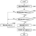
- FIG. 1 is a flowchart illustrating a first example of processing related to a notification control method in the power receiving device according to the present embodiment.
- the process of steps S100 to S108 shown in FIG. 1 corresponds to the first determination process in the process (1) (determination process), and the process of step S110 shown in FIG. Notification control processing).
- the power receiving device communicates with a connected external device (S100). Then, the power receiving device according to the present embodiment determines whether or not the power identification information is received through communication with the connected external device (S102).
- the power receiving apparatus determines whether or not the transmitted power is to be charged based on the received power identification information. (S104).
- the power receiving apparatus according to the present embodiment determines that the transmitted power is a charging target when, for example, the received power identification information indicates the charging target power.
- step S104 determines that the transmitted power is a charging target
- the power receiving apparatus determines that the transmitted power is a charging target (S106).
- the power receiving apparatus performs processing in step S108 described later.
- step S102 If it is not determined in step S102 that the power identification information has been received, or if it is not determined in step S104 that the power transmitted is to be charged, the power receiving apparatus according to the present embodiment charges the transmitted power.
- the target is not determined (S108).
- the power receiving device for example, causes a notification unit (described later) included in the power receiving device according to the present embodiment and / or an external device to perform notification based on the determination result in step S106 or step S108 (S110). ).
- a notification unit described later included in the power receiving device according to the present embodiment and / or an external device to perform notification based on the determination result in step S106 or step S108 (S110).
- the power receiving apparatus performs, for example, the process illustrated in FIG. 1 as the process related to the notification control method. For example, by performing the process shown in FIG. 1, the first determination process according to the present embodiment and the process (2) (notification control process) are realized.
- the process which concerns on the notification control method in the power receiving apparatus which concerns on this embodiment is not restricted to the process shown in FIG.
- FIG. 2 is a flowchart illustrating a second example of processing related to the notification control method in the power receiving device according to the present embodiment.
- the process of steps S200 to S206 shown in FIG. 2 corresponds to the second determination process in the process (1) (determination process), and the process of step S208 shown in FIG. Notification control processing).
- the power receiving device determines, for example, whether or not packetized power identification information has been received (whether or not it has been detected) (S200).
- step S200 When it is determined in step S200 that the power identification information has been received, the power receiving apparatus according to the present embodiment is transmitted based on the received power identification information, as in the process of step S104 in FIG. It is determined whether or not power is charged (S202).
- step S202 When it is determined in step S202 that the transmitted power is a charging target, the power receiving apparatus according to the present embodiment determines that the transmitted power is a charging target (S204). In addition, when it is not determined in step S202 that the electric power transmitted is a billing target, the power receiving apparatus according to the present embodiment performs a process in step S206 described later.
- step S200 If it is not determined in step S200 that the power identification information has been received, or if it is not determined in step S202 that the power transmitted is to be charged, the power receiving apparatus according to the present embodiment charges the transmitted power.
- the target is not determined (S206).
- the power receiving device for example, causes a notification unit (described later) included in the power receiving device according to the present embodiment and / or an external device to perform notification based on the determination result in step S204 or step S206 (S208). ).
- a notification unit described later included in the power receiving device according to the present embodiment and / or an external device to perform notification based on the determination result in step S204 or step S206 (S208).
- the power receiving apparatus performs, for example, the process illustrated in FIG. 2 as the process related to the notification control method. For example, by performing the process shown in FIG. 2, the second determination process according to the present embodiment and the process (2) (notification control process) are realized.
- the process which concerns on the notification control method in the power receiving apparatus which concerns on this embodiment is not restricted to the process shown with reference to FIG. 1, and the process shown with reference to FIG.
- the power receiving apparatus according to the present embodiment uses the power identification information received by communication with the connected external apparatus or the packetized power identification received via the power line in the process of step S102 illustrated in FIG. Based on the information, it may be determined whether power identification information is received.
- the power receiving apparatus according to the present embodiment determines, for example, whether or not the transmitted power is a chargeable object by performing one of the first determination process and the second determination process. It is also possible to notify the user whether the power to be charged is the power to be charged.
- a connected external device that communicates with the power receiving device according to the present embodiment may be referred to as a “power supply device”.
- Examples of communication performed between the power receiving device according to the present embodiment and the power feeding device (connected external device) according to the present embodiment include wireless communication and power line communication (wired communication).
- the power receiving device for example, wireless communication using a wireless communication technology such as NFC (Near Field Communication) technology or RFID (Radio Frequency IDentification) technology is used. Is done.
- power line communication is performed between the power receiving device according to the present embodiment and the power feeding device according to the present embodiment, for example, by applying wireless communication technology such as NFC communication technology or RFID technology to wired communication. Is called.
- the power line communication according to the present embodiment includes, for example, communication performed by contact of terminals of each device (so-called contact communication) and communication performed by connecting terminals of each device by wire. It is.
- the power supply apparatus includes, for example, a high-frequency signal generation unit (described later) that generates a high-frequency signal, and transmits the high-frequency signal to a connected external device. That is, the power supply apparatus according to the present embodiment has a so-called reader / writer function, for example.
- the power receiving device performs communication with the external device by performing load modulation based on a signal transmitted from the external device such as the power feeding device according to the present embodiment.
- the power receiving device receives a high-frequency signal transmitted from the power feeding device according to the present embodiment
- the power receiving device is driven by obtaining power from the received high-frequency signal and processes the received high-frequency signal.
- a high frequency signal is transmitted by performing load modulation based on the result.
- the power receiving device according to the present embodiment and the power feeding device according to the present embodiment perform the above-described processes, respectively, so that the power receiving device according to the present embodiment and the power feeding device according to the present embodiment Between, wireless communication according to the present embodiment or power line communication according to the present embodiment is realized.
- examples of the high-frequency signal according to the present embodiment include a frequency signal used in RFID and a frequency signal used in non-contact communication.
- the frequency of the high-frequency signal is 130 to 135 [kHz], 13.56 [MHz], 56 [MHz], 433 [MHz], 954.2 [MHz], 954.8 [MHz], 2441.75. [MHz] and 2448.875 [MHz] are mentioned, but the frequency of the high-frequency signal according to the present embodiment is not limited to the above.
- the high frequency transmitted based on the high frequency signal according to the present embodiment may be referred to as “carrier wave”.
- the wireless communication according to the present embodiment and the power line communication according to the present embodiment are not limited to communication using wireless communication technology such as NFC communication technology or RFID technology.
- wireless communication technology such as NFC communication technology or RFID technology
- wireless communication technology such as NFC communication technology or RFID technology
- the power receiving device according to the present embodiment and the power feeding device according to the present embodiment wireless communication of an arbitrary method such as wireless communication based on IEEE802.11b, PLC (Power Line Communication), etc. Power line communication may be performed.
- wireless communication technology such as NFC communication technology or RFID technology
- the power receiving device according to the present embodiment and the power supply device according to the present embodiment will be described as an example. Communication according to the embodiment will be described.
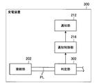
- FIG. 3 is an explanatory diagram for explaining an example of wireless communication according to the present embodiment.
- the wireless communication according to the present embodiment will be described using the power feeding device 100A and the power receiving device 200A illustrated in FIG. 3 as examples.
- components related to wireless communication according to the present embodiment are illustrated in the configuration of the power feeding device according to the present embodiment and the configuration of the power receiving device according to the present embodiment.
- a plug is shown as the power receiving device 200A, but the power receiving device according to the present embodiment is not limited to a plug.
- the power feeding apparatus 100A includes, for example, a connection unit 102, a wireless communication unit 104, and a control unit 106.
- the power receiving device 200 ⁇ / b> A includes, for example, a connection unit 202 and a wireless communication unit 204.
- the connection unit 102 connects the power line PL through which power is transmitted to an external device. Further, the connection unit 102 may be provided with a connection assisting member for assisting in maintaining the connection state of the connected external device.
- examples of the power line PL according to the present embodiment include an alternating current having a predetermined frequency such as 50 [Hz] and 60 [Hz], and a power line through which a direct current flows.
- a connection auxiliary member which concerns on this embodiment a magnet etc. are mentioned, for example.
- a case where an alternating current having a predetermined frequency flows through the power line PL will be described as an example.
- connection unit 102 has a terminal connected to power line PL, and connection unit 202 is connected to power line PL (corresponding to an external power line when viewed from power supply apparatus 100A). Terminal. Then, the terminal included in the connection unit 102 and the terminal included in the connection unit 202 are electrically connected to each other, so that the power supply apparatus 100A and the power reception apparatus 200A (when viewed from the power supply apparatus 100A, this corresponds to an external device). .) Is connected.
- “the electrical connection between the terminal included in the connection unit 102 and the terminal included in the connection unit 202” refers to, for example, contact of a terminal included in the connection unit of each device, or each device. This means that the terminals of the connection part are connected by wire.
- the connection unit 202 may include a connection assisting member for assisting in maintaining the connection state of the connected external device, similarly to the connection unit 102 included in the power supply apparatus 100A.
- connection unit 102 detects, for example, a change in the connection state of the external device (change from the unconnected state to the connected state / change from the connected state to the unconnected state). Then, the connection unit 102 transmits a detection signal indicating the detection (detection result) to the control unit 106. Note that when the wireless communication unit 104 has a function of transmitting a high-frequency signal in response to transmission of the detection signal, the connection unit 102 may transmit the detection signal to the wireless communication unit 104. Good.
- connection unit 102 includes, for example, a switch that detects a physical connection state of the external device, and transmits a detection signal to the control unit 106 when the state of the switch changes. Is not limited to the above.
- the connection unit 102 according to the present embodiment has a function related to, for example, detection of a change in the connection state of the external apparatus. You don't have to.
- the wireless communication unit 104 and the wireless communication unit 204 serve to perform wireless communication according to the present embodiment.
- the communication in the wireless communication unit 104 is controlled by the control unit 106, for example.
- the control unit 106 is configured by an MPU (Micro Processing Unit), an integrated circuit in which various processing circuits are integrated, and the like, and controls each unit of the power supply apparatus 100A. More specifically, the control unit 106, for example, based on a detection signal transmitted from the connection unit 102 or a response signal from a connected external device such as the power receiving device 200B transmitted from the power line communication unit 108, A generation command and a high-frequency signal transmission stop command are transmitted to the power line communication unit 108 to control communication in the power line communication unit 108.
- MPU Micro Processing Unit
- FIG. 4 is an explanatory diagram illustrating an example of a configuration for realizing wireless communication performed between the power receiving device according to the present embodiment and the power feeding device according to the present embodiment.
- FIG. 4 illustrates an example of a configuration of the wireless communication unit 104 and the control unit 106 included in the power feeding device 100A illustrated in FIG. 3 and the wireless communication unit 204 included in the power receiving device 200A illustrated in FIG.
- the wireless communication unit 104 included in the power supply apparatus includes, for example, a high frequency signal generation unit 150, a high frequency transmission unit 152, and a demodulation unit 154. Further, the wireless communication unit 104 transmits a high-frequency signal in response to a high-frequency signal generation command transmitted from the control unit 106 and transmits a high-frequency signal in response to a high-frequency signal transmission stop command transmitted from the control unit 106, for example. To stop.
- the wireless communication unit 104 includes, for example, an encryption circuit (not shown) for encrypting communication, a communication collision prevention (anti-collision) circuit, a connection interface for connecting to an external device or another circuit ( (Not shown) or the like.
- the wireless communication unit 104 connects each component by a bus as a data transmission path, for example.
- the connection interface include a UART (Universal Asynchronous Receiver Transmitter), a LAN (Local Area Network) terminal, and a transmission / reception circuit.
- the high frequency signal generation unit 150 receives a high frequency signal generation command from the control unit 106 and generates a high frequency signal according to the high frequency signal generation command.
- an AC power supply is shown as the high-frequency signal generation unit 150, but the high-frequency signal generation unit 150 according to the present embodiment is not limited to the above.
- the high-frequency signal generation unit 150 according to the present embodiment includes a modulation circuit (not shown) that modulates ASK (Amplitude Shift Keying) and an amplification circuit (not shown) that amplifies the output of the modulation circuit. Can do.
- the high-frequency signal generated by the high-frequency signal generation unit 150 for example, a high-frequency signal including an identification information transmission request for requesting transmission of identification information from the connected external device, various processing instructions for the connected external device, and processing are performed.
- a high frequency signal including data for example, a high frequency signal including data.
- the high frequency signal generated by the high frequency signal generation unit 150 is not limited to the above.
- the high-frequency signal according to the present embodiment may be a signal (for example, an unmodulated signal) that serves to supply power to the power line communication unit 208 of the power receiving device 200A described later.
- the high-frequency transmission unit 152 includes, for example, a coil (inductor) L1 having a predetermined inductance, and transmits a carrier wave corresponding to the high-frequency signal generated by the high-frequency signal generation unit 150. Moreover, the high frequency transmission part 152 can also receive the response signal from a connection external device. That is, the high frequency transmission unit 152 can serve as a communication antenna of the wireless communication unit 104.
- FIG. 4 shows an example in which the high-frequency transmission unit 152 is configured by the coil L1, but the constituent waves of the high-frequency transmission unit 152 according to the present embodiment are not limited to the above.
- the high frequency transmission unit according to the present embodiment may form a resonance circuit by further including a capacitor.
- the demodulator 154 demodulates the response signal from the connected external device, for example, by detecting the change in the amplitude of the voltage at the antenna end of the high-frequency transmitter 152, and binarizing the detected signal.
- the means for demodulating the response signal in the demodulator 154 is not limited to the above.
- the demodulator 154 can demodulate the response signal using the phase change of the voltage at the antenna end of the high-frequency transmitter 152.
- the demodulator 154 transmits the demodulated response signal to the controller 106. Then, the control unit 106 having the demodulated response signal transmitted to the control unit 106 performs various processes such as processing data corresponding to the response signal and generating a high-frequency signal generation command based on the processing result. Do.
- the wireless communication unit 104 transmits a carrier wave by the configuration shown in FIG. 4, for example, and demodulates a response signal transmitted from a connected external device such as the power receiving device 200A.
- a connected external device such as the power receiving device 200A.
- the configuration of the wireless communication unit 104 according to the present embodiment is not limited to the configuration illustrated in FIG. 4.
- Wireless communication unit 204 included in the power receiving device includes a communication antenna 250 and an IC chip 252.
- the wireless communication unit 204 connects each component with a bus 272 as a data transmission path, for example.
- the communication antenna 250 receives a carrier wave transmitted from a connected external device such as the power supply device 100 ⁇ / b> A, and transmits a response signal based on the processing result of the processing in the IC chip 252.
- the communication antenna 250 includes a resonance circuit including a coil (inductor) L2 having a predetermined inductance and a capacitor C1 having a predetermined capacitance, and generates an induced voltage by electromagnetic induction in response to reception of a carrier wave. Let Then, the communication antenna 250 outputs a reception voltage obtained by resonating the induced voltage at a predetermined resonance frequency.
- the resonance frequency in the communication antenna 250 is set in accordance with the frequency of the carrier wave such as 13.56 [MHz], for example.
- the communication antenna 250 receives a carrier wave with the above configuration and transmits a response signal by load modulation performed in a load modulation unit 264 (described later) provided in the IC chip 252.
- the IC chip 252 demodulates and processes the high-frequency signal based on the received carrier wave, and transmits a response signal from the communication antenna 250 by load modulation.
- the IC chip 252 serves as a substantial wireless communication unit that performs wireless communication in the wireless communication unit 204.
- the IC chip 252 includes, for example, a carrier detection unit 254, a detection unit 256, a regulator 258, a demodulation unit 260, a data processing unit 262, a load modulation unit 264, a ROM (Read Only Memory) 266, and a RAM ( Random Access Memory) 268 and internal memory 270. Further, the data processing unit 262, the ROM 266, the RAM 268, and the internal memory 270 are connected by, for example, a bus 272 as a data transmission path.
- the IC chip 252 may further include, for example, a protection circuit (not shown) for preventing an overvoltage or overcurrent from being applied to the data processing unit 262. .
- a protection circuit for example, a clamp circuit constituted by a diode or the like can be cited.
- the carrier detection unit 254 generates, for example, a rectangular detection signal based on the reception voltage transmitted from the communication antenna 250 and transmits the detection signal to the data processing unit 262. Further, the data processing unit 262 uses the transmitted detection signal as a processing clock for data processing, for example.
- the detection signal is based on the received voltage transmitted from the communication antenna 250, it is synchronized with the frequency of the carrier wave transmitted from the connected external device. Therefore, the IC chip 252 includes the carrier detection unit 254, so that processing with the connected external device can be performed in synchronization with the connected external device.
- the detection unit 256 rectifies the reception voltage output from the communication antenna 250.
- the detection unit 256 includes, for example, a diode D1 and a capacitor C2.
- the regulator 258 smoothes and constants the received voltage and outputs a drive voltage to the data processing unit 262.
- the regulator 258 uses, for example, a DC component of the received voltage as a drive voltage.
- the demodulator 260 demodulates the high-frequency signal based on the received voltage, and outputs data corresponding to the high-frequency signal included in the carrier wave (for example, a binarized data signal of high level and low level).
- the demodulator 260 outputs, for example, the AC component of the received voltage as data.
- the data processing unit 262 drives, for example, the drive voltage output from the regulator 258 as a power source, and processes the data demodulated by the demodulation unit 260.
- the data processing unit 262 includes, for example, an MPU and various processing circuits.
- the data processing unit 262 selectively generates a control signal for controlling load modulation related to a response to the connected external device according to the processing result. Then, the data processing unit 262 selectively outputs the control signal to the load modulation unit 264.
- the data processing unit 262 performs reading and updating of data stored in the internal memory 270 based on, for example, an instruction included in the data demodulated by the demodulation unit 260.
- the load modulation unit 264 includes, for example, a load Z and a switch SW1, and performs load modulation by selectively connecting (enabling) the load Z according to a control signal transmitted from the data processing unit 262.
- the load Z is constituted by a resistor having a predetermined resistance value, for example, but the load Z is not limited to the above.
- the switch SW1 is constituted by, for example, a p-channel type MOSFET (Metal Oxide Semiconductor Field Effect Transistor) or an n-channel type MOSFET, but the switch SW1 is not limited to the above.
- the ROM 266 stores control data such as programs and calculation parameters used by the data processing unit 262.
- the RAM 268 temporarily stores programs executed by the data processing unit 262, calculation results, execution states, and the like.
- the internal memory 270 is a storage unit included in the IC chip 252 and has, for example, tamper resistance.
- the data processing unit 262 performs reading of data, writing of new data, and updating of data.
- the internal memory 270 stores various data such as identification information, electronic value (money or data having value according to money), and applications.
- the identification information according to the present embodiment is information indicating the power receiving device according to the present embodiment (for example, information that an external device can use to identify the power receiving device according to the present embodiment).
- identification information for example, data indicating the identification number unique to the power receiving apparatus according to the present embodiment, data indicating the type of the power receiving apparatus according to the present embodiment (for example, data indicating the manufacturer, model number, etc.), Examples include power waveform data indicating a power waveform when the power receiving device according to the embodiment is used (when the power receiving device according to the present embodiment is driven).
- FIG. 4 shows an example in which the internal memory 270 stores the identification information 274 and the electronic value 276, the data stored in the internal memory 270 is not limited to the above.
- the IC chip 252 processes the high-frequency signal received by the communication antenna 250, for example, with the above-described configuration shown in FIG. 4, and transmits a response signal from the communication antenna 250 by load modulation.
- the wireless communication unit 204 includes, for example, the communication antenna 250 and the IC chip 252 to process a high-frequency signal transmitted from a connected external device such as the power supply device 100A and transmit a response signal by load modulation.
- a connected external device such as the power supply device 100A
- the configuration of the wireless communication unit 204 according to the present embodiment is not limited to the configuration illustrated in FIG.
- the wireless communication unit 204 does not have to include, for example, each component configuring the IC chip 252 illustrated in FIG. 4 in the form of an IC (Integrated Circuit) chip.
- the power receiving device according to the present embodiment and the power feeding device according to the present embodiment include, for example, the wireless communication unit 104 illustrated in FIG. 4 included in the power feeding device according to the present embodiment, and the wireless communication unit 204 illustrated in FIG.
- wireless communication can be performed using a wireless communication technology such as a communication technology using NFC.
- the stored information can be transmitted.
- the power receiving device in a communication system including the power receiving device according to the present embodiment and the power feeding device according to the present embodiment, the power receiving device according to the present embodiment communicates wirelessly without having a separate power supply circuit for performing communication. Can be done.
- the power receiving apparatus can transmit stored information by performing load modulation, for example, even if a signal corresponding to a user operation (a signal indicating a user instruction) is not input. .
- FIG. 5 is an explanatory diagram for explaining an example of power line communication according to the present embodiment.
- the power line communication according to the present embodiment will be described using the power feeding device 100B and the power receiving device 200B illustrated in FIG. 5 as examples.
- the component which concerns on the power line communication which concerns on this embodiment is shown among the structure of the electric power feeder which concerns on this embodiment, and the structure of the power receiving apparatus which concerns on this embodiment.
- the component which concerns on the power line communication in the power receiving apparatus which concerns on this embodiment may be provided in the plug like the power receiving apparatus 200A shown, for example in FIG.
- the power supply apparatus 100B includes, for example, a connection unit 102, a control unit 106, a power line communication unit 108, a first filter 110, and a second filter 112.
- the power supply apparatus 100B may include, for example, a ROM (not shown), a RAM (not shown), a storage unit (not shown), and the like.
- the power supply apparatus 100 ⁇ / b> B connects each component by a bus as a data transmission path.
- the ROM (not shown) stores control data such as a program used by the control unit 106 and calculation parameters.
- a RAM (not shown) temporarily stores a program executed by the control unit 106.
- the storage unit (not shown) stores various data such as identification information and applications acquired from a connected external device such as the power receiving device 200B.
- a magnetic recording medium such as a hard disk, EEPROM (Electrically Erasable and Programmable Read Only Memory), flash memory (flash memory), MRAM (Magnetoresistive Random Access Memory), FeRAM (Nonvolatile memory) such as (Ferroelectric Random Access Memory) and PRAM (Phase change Random Access Memory).
- the storage unit (not shown) may be detachable from the power supply apparatus 100B.
- the control unit 106 includes an integrated circuit in which an MPU and various processing circuits are integrated, and controls each unit of the power supply apparatus 100B. More specifically, the control unit 106, for example, based on a detection signal transmitted from the connection unit 102 or a response signal from a connected external device such as the power receiving device 200B transmitted from the power line communication unit 108, A generation command and a high-frequency signal transmission stop command are transmitted to the power line communication unit 108 to control communication in the power line communication unit 108. The control unit 106 transmits a high-frequency signal generation command or a high-frequency signal transmission stop command to the power line communication unit 108 based on the detection signal, so that the connection is an external device that is actually connected via the power line. Communication with an external device is possible.
- the control unit 106 transmits the high-frequency signal generation command and the high-frequency signal transmission stop command to the power line communication unit 108 as described above, so that the power line communication unit 108 can detect the high frequency signal based on the detection result in the connection unit 102, for example. A signal can be transmitted.
- the control unit 106 transmits a high-frequency signal generation command or a high-frequency signal transmission stop command to the power line communication unit 108 based on the response signal, so that the power line between the power receiving device 200B and the connected external device It is possible to control communication through the network.
- control unit 106 periodically / non-periodically transmits a high-frequency signal generation command to the power line communication unit 108 to cause the power line communication unit 108 to transmit a high-frequency signal periodically / non-periodically. May be.
- the power line communication unit 108 serves to perform communication with a connected external device such as the power receiving device 200B via the power line.
- FIG. 6 is an explanatory diagram illustrating an example of a configuration of the power line communication unit 108 included in the power supply apparatus 100B according to the present embodiment.
- the power line communication unit 108 includes, for example, a high-frequency signal generation unit 156 and a demodulation unit 158, and serves as a reader / writer (or interrogator) in NFC or the like.
- the power line communication unit 108 may further include, for example, an encryption circuit (not shown), a communication collision prevention (anti-collision) circuit, and the like.
- the high frequency signal generation unit 156 receives a high frequency signal generation command transmitted from the control unit 106, for example, and generates a high frequency signal corresponding to the high frequency signal generation command. In addition, the high frequency signal generation unit 156 receives a high frequency signal transmission stop command transmitted from the control unit 106 and indicating transmission stop of the high frequency signal, for example, and stops generating the high frequency signal.
- an AC power source is shown as the high-frequency signal generation unit 156, but the high-frequency signal generation unit 156 according to the present embodiment is not limited to the above.
- the high-frequency signal generation unit 132 according to the present embodiment can include a modulation circuit (not shown) that performs ASK modulation and an amplification circuit (not shown) that amplifies the output of the modulation circuit.
- the high-frequency signal generated by the high-frequency signal generation unit 156 includes, for example, a high-frequency signal including an identification information transmission request for requesting transmission of identification information from the connected external device, various processing instructions for the connected external device, and processing.
- a high frequency signal including data For example, the high-frequency signal generated by the high-frequency signal generation unit 156 is not limited to the above.
- the high-frequency signal according to the present embodiment may be a signal (for example, an unmodulated signal) that serves to supply power to the power line communication unit 208 of the power receiving device 200B described later.
- the demodulator 158 detects a change in the amplitude of the voltage between the high-frequency signal generator 156 and the first filter 110, and binarizes the detected signal, thereby transmitting a response transmitted from the connected external device. Demodulate the signal. Then, the demodulation unit 158 transmits the demodulated response signal (for example, a response signal indicating identification information or a response signal indicating a response based on processing according to the harmonic signal) to the control unit 106.
- the demodulator of the response signal in the demodulator 158 is not limited to the above.
- the demodulator 158 demodulates the response signal using the phase change of the voltage between the high frequency signal generator 156 and the first filter 110. You can also
- the power line communication unit 108 serves as a reader / writer in NFC or the like, for example, with the configuration shown in FIG. 6, and serves to communicate with a connected external device via the power line. it can.
- FIG. 7 is an explanatory diagram illustrating another example of the power line communication unit 108 provided in the power supply apparatus 100B according to the present embodiment.
- the control unit 106 and the first filter 110 are shown together.
- the power line communication unit 108 includes a high frequency signal generation unit 156, a demodulation unit 158, a first high frequency transmission / reception unit 160, and a second high frequency transmission / reception unit 162.
- the power line communication unit 108 according to another example may further include, for example, an encryption circuit (not shown), a communication collision prevention (anti-collision) circuit, and the like.
- the high-frequency signal generation unit 156 generates a high-frequency signal according to the high-frequency signal generation command and stops the generation of the high-frequency signal according to the high-frequency signal transmission stop command, similarly to the high-frequency signal generation unit 156 shown in FIG.
- the demodulation unit 158 demodulates the response signal transmitted from the connected external device by envelope-detecting the voltage amplitude change at the antenna end of the high-frequency signal generation unit 156 and binarizing the detected signal. Note that the demodulator of the response signal in the demodulator 158 is not limited to the above, and the demodulator 158 can also demodulate the response signal using, for example, the phase change of the voltage at the antenna end of the high-frequency signal generator 156.
- the first high-frequency transmission / reception unit 160 includes, for example, a coil (inductor; hereinafter the same) L3 having a predetermined inductance and a capacitor C3 having a predetermined capacitance to constitute a resonance circuit.
- the resonance frequency of the first high-frequency transmission / reception unit 156 for example, the frequency of a high-frequency signal such as 13.56 [MHz] can be cited.
- the 1st high frequency transmission / reception part 160 transmits the high frequency signal which the high frequency signal generation part 156 produced
- the second high frequency transmitting / receiving unit 162 includes, for example, a coil L4 having a predetermined inductance and a capacitor C4 having a predetermined capacitance, and constitutes a resonance circuit.
- the resonance frequency of the second high-frequency transmission / reception unit 162 for example, the frequency of a high-frequency signal such as 13.56 [MHz] can be cited.
- the 2nd high frequency transmission / reception part 162 can receive the high frequency signal transmitted from the 1st high frequency transmission / reception part 160 by the said structure, and can transmit the response signal transmitted from the connection external apparatus. That is, the second high frequency transmission / reception unit 162 serves as a second communication antenna in the power line communication unit 108.
- the power line communication unit 108 serves as a reader / writer in NFC or the like and communicates with a connected external device via the power line. It can fulfill the role of communicating between the two.
- First filter 110 is connected between power line communication unit 108 and power line PL, and serves to filter a signal transmitted from power line PL. More specifically, the first filter 110 blocks a signal having a frequency of power supplied to a connected external device such as the power receiving device 200B through at least the power line from among signals transmitted from the power line PL, and thereby a high-frequency signal. It has a function not to shut off. The power supply apparatus 100B does not transmit a signal having a frequency of power that may become noise by including the first filter 110 to the power line communication unit 108.
- the power line communication unit 108 and a connected external device (more precisely, for example, a power reception device described later) It is possible to improve the accuracy of communication with a power line communication unit 208 included in a connected external device, such as the 200B power line communication unit 208.
- FIG. 8 is an explanatory diagram illustrating an example of the configuration of the first filter 110 included in the power supply apparatus 100B according to the present embodiment.
- the first filter 110 includes inductors L5 and L6, capacitors C5 to C7, and surge absorbers SA1 to SA3. Needless to say, the configuration of the first filter 110 according to the present embodiment is not limited to the configuration illustrated in FIG. 8.
- the second filter 112 is provided on the power line PL between the connection unit 102 and the power source, and serves to filter a signal that can be transmitted from the connection unit 102 side.
- the power source according to the present embodiment include an external power source such as a commercial power source and an internal power source such as a battery.
- the second filter 112 blocks at least a high-frequency signal transmitted by the power line communication unit 108 and a high-frequency signal transmitted by the connected external device, and outputs a signal of the frequency of power supplied to the connected external device. Has the function of not blocking.
- the power supply apparatus 100B can block, for example, a high-frequency signal related to communication via the power line and a noise component such as a noise component that can be transmitted from the connected external apparatus side. That is, the second filter 112 serves as a so-called power splitter.
- FIG. 9 is an explanatory diagram illustrating an example of the configuration of the second filter 112 included in the power supply apparatus 100B according to the present embodiment.
- the second filter 112 includes inductors L7 and L8, a capacitor C8, and a surge absorber SA4. Needless to say, the configuration of the second filter 112 according to the present embodiment is not limited to the configuration shown in FIG. 9.
- the power supply device 100B can communicate with a connected external device such as the power receiving device 200B connected to the connection unit 102 via a power line, for example, with the configuration shown in FIG. Further, the power supply apparatus 100B according to the present embodiment performs predetermined processing based on the transmitted high-frequency signal, such as transmission of identification information and billing processing using electronic value, for example, with the configuration illustrated in FIG. The device can be made to do.
- the power receiving device 200B includes, for example, a connection unit 202, a first filter 206 (communication filter), a power line communication unit 208, and a second filter 210.
- the power reception device 200B has, for example, a battery (not shown) or a function that the power reception device 200B has in the subsequent stage of the second filter 210 (on the side opposite to the power supply device 100B in the second filter 210 illustrated in FIG. 5).
- a battery not shown
- the power receiving device 200B can charge the battery (not shown) supplied with power from a connected external device such as the power supply device 100B via the power line, and uses the supplied power.
- the functions of the power receiving device 200B can be realized.
- the power receiving device 200B when the power receiving device 200B is a vehicle such as an electric vehicle, the power receiving device 200B receives power supply, charges a built-in battery, and rotates wheels using the power of the battery.
- the power receiving apparatus 200B includes a display device capable of displaying images (moving images / still images) and / or characters, the power receiving apparatus 200B receives power supply and displays the display screen of the display device. Display images and characters.
- the display device may serve as a notification unit (described later) in the power receiving device according to the present embodiment.
- the first filter 206 is connected between the power line (strictly, the power line PL in the power receiving apparatus 200B) and the power line communication unit 208, and plays a role of filtering a signal transmitted from the power line. More specifically, the first filter 206 has a function of blocking at least a power frequency signal among signals transmitted from the power line and not blocking a high-frequency signal.
- the power receiving device 200B does not transmit a signal having a frequency of power that may become noise by including the first filter 206 to the power line communication unit 208. Therefore, the power receiving device 200B and the connected external device (more strictly, for example, the power supply device 100B It is possible to improve the accuracy of communication with a power line communication unit provided in a connected external device, such as the power line communication unit 108.
- the first filter 206 has the same configuration as the first filter 110 of the power supply apparatus 100B shown in FIG. 8, for example. Needless to say, the configuration of the first filter 206 according to the present embodiment is not limited to the configuration shown in FIG. 8.
- the power line communication unit 208 communicates with a connected external device such as the power supply device 100B via a power line by a high frequency signal. More specifically, for example, when the power line communication unit 208 receives a high-frequency signal transmitted from an external connection device, the power-line communication unit 208 obtains power from the high-frequency signal and drives to perform processing based on the received high-frequency signal. Do. And the power line communication part 208 transmits the response signal according to the said process as a high frequency signal by load modulation.
- the power line communication unit 208 when the power line communication unit 208 receives a high-frequency signal including an identification information transmission request for requesting transmission of identification information, the power line communication unit 208 displays the stored identification information based on the identification information transmission request included in the high-frequency signal. read out. Then, the power line communication unit 208 transmits the read identification information superimposed on the power line by load modulation. For example, when the power line communication unit 208 receives a high frequency signal including various processing instructions and data to be processed, the power line communication unit 208 performs processing based on the processing instructions and data included in the high frequency signal. Then, the power line communication unit 208 transmits a response signal based on the above processing by superimposing it on the power line by load modulation. That is, the power line communication unit 208 serves as a responder in NFC, for example.
- the power line communication unit 208 leads the process related to the notification control method according to the present embodiment (for example, the process (1) (determination process) and the process (2) (notification control process)). Play a role to do. More specifically, as described above, the power line communication unit 208 communicates with a connected external device such as the power supply device 100B via the power line by performing load modulation, and is transmitted from the connected external device. Based on the above, it is determined whether the transmitted power is charged (corresponding to the process (1) (determination process)). In addition, the power line communication unit 208 is connected to a notification unit (described later) included in the power receiving device according to the present embodiment and / or an external device based on the determination result in the process (1) (determination process), for example. Then, a notification based on the determination result is performed (corresponding to the process (2) (notification control process)).
- a notification unit included in the power receiving device according to the present embodiment and / or an external device based on the determination result in the process (1) (determination process), for example. The
- FIG. 10 is an explanatory diagram illustrating an example of the configuration of the power line communication unit 208 included in the power receiving device 200B according to the present embodiment.
- the first filter 206 is also shown.
- FIG. 10 illustrates a configuration in which the power line communication unit 208 includes an IC chip 280 that demodulates and processes received harmonic signals and transmits a response signal by load modulation. Note that the power line communication unit 208 according to the present embodiment may not include each component configuring the IC chip 280 illustrated in FIG. 10 in the form of an IC chip.
- the IC chip 280 includes, for example, a detection unit 254, a detection unit 256, a regulator 258, a demodulation unit 260, a data processing unit 262, and a load modulation unit 264.
- the IC chip 280 may further include, for example, a protection circuit (not shown) for preventing an overvoltage or overcurrent from being applied to the data processing unit 262.
- a protection circuit for example, a clamp circuit constituted by a diode or the like can be cited.
- the IC chip 280 includes, for example, a ROM 234, a RAM 236, and an internal memory 238.
- the data processing unit 262, the ROM 234, the RAM 236, and the internal memory 238 are connected by, for example, a bus 240 as a data transmission path.
- the IC chip 280 is as follows. It can be seen that the configuration is the same as that of the IC chip 252 shown in FIG.
- the IC chip 252 illustrated in FIG. 4 receives a high frequency signal based on the carrier wave received by the communication antenna 250, and the IC chip 252 demodulates the high frequency signal based on the carrier wave received by the communication antenna 250.
- the response signal is transmitted from the communication antenna 250 by load modulation.
- the IC chip 280 receives a high frequency signal transmitted from the first filter 206 and transmitted from a connected external device such as the power feeding device 100B.
- the IC chip 280 has the same configuration as the IC chip 252 shown in FIG. Therefore, like the IC chip 252 shown in FIG. 4, the IC chip 280 can demodulate and process the input high-frequency signal and transmit a response signal corresponding to the high-frequency signal by load modulation.
- the IC chip 280 is connected to the first filter 206 as shown in FIG. 10, and the first filter 206 is connected to the power line PL as shown in FIG. Therefore, the response signal transmitted from the IC chip 280 is superimposed on the power line via the first filter 206.
- the IC chip 280 processes the received high-frequency signal, for example, with the configuration shown in FIG. 10, and transmits the response signal superimposed on the power line by load modulation.
- the configuration of the IC chip 280 according to the present embodiment is not limited to the configuration shown in FIG.
- the power line communication unit 208 obtains power from the received high-frequency signal, performs processing indicated by the received high-frequency signal, for example, with the configuration shown in FIG. 10, and transmits a response signal corresponding to the processing by load modulation. Can do.
- FIG. 11 is an explanatory diagram illustrating another example of the configuration of the power line communication unit 208 included in the power receiving device 200B according to the present embodiment.
- the 1st filter 206 is shown collectively.
- the power line communication unit 208 according to the present embodiment does not have to include each component configuring the IC chip 280 illustrated in FIG. 11 in the form of an IC chip.
- the power line communication unit 208 includes a first high frequency transmission / reception unit 282, a second high frequency transmission / reception unit 284, and an IC chip 280.
- the first high frequency transmitting / receiving unit 282 includes, for example, a coil L9 having a predetermined inductance and a capacitor C9 having a predetermined capacitance, and constitutes a resonance circuit.
- the resonance frequency of the first high-frequency transmission / reception unit 282 for example, the frequency of a high-frequency signal such as 13.56 [MHz] can be cited.
- the first high frequency transmitter / receiver 282 can transmit the high frequency signal transmitted from the first filter 206 and can receive the response signal transmitted from the second high frequency transmitter / receiver 284 with the above configuration. That is, the first high frequency transmitting / receiving unit 282 serves as a first communication antenna in the power line communication unit 208.
- the second high frequency transmission / reception unit 284 includes, for example, a coil L10 having a predetermined inductance and a capacitor C10 having a predetermined capacitance, and constitutes a resonance circuit.
- the resonance frequency of the second high-frequency transmitting / receiving unit 284 for example, the frequency of a high-frequency signal such as 13.56 [MHz] can be cited.
- the second high frequency transmitting / receiving unit 284 can receive the high frequency signal transmitted from the first high frequency transmitting / receiving unit 282 and transmit a response signal with the above configuration.
- the second high frequency transmission / reception unit 284 generates an induced voltage by electromagnetic induction in response to reception of the high frequency signal, and outputs the received voltage obtained by resonating the induced voltage at a predetermined resonance frequency to the IC chip 280. To do. Further, the second high frequency transmitting / receiving unit 284 transmits a response signal by load modulation performed in the load modulation unit 264 included in the IC chip 280. That is, the second high frequency transmission / reception unit 284 serves as a second communication antenna in the power line communication unit 208.
- the IC chip 280 performs processing in the same manner as the IC chip 280 shown in FIG. 10 based on the reception voltage transmitted from the second high frequency transmission / reception unit 284.
- the power line communication unit 208 obtains power from the received high-frequency signal and performs processing indicated by the received high-frequency signal, similarly to the configuration shown in FIG. 10, and performs load modulation. A response signal corresponding to the processing can be transmitted.
- the power line communication unit 208 has the configuration shown in FIG. 11, for example, an IC chip related to NFC or RFID can be used, which has an advantage that mounting is easier.
- the second filter 210 serves to filter a signal that can be transmitted from the connected external apparatus side such as the power supply apparatus 100B via the power line PL. More specifically, the second filter 210 intercepts at least a high-frequency signal transmitted by the connected external device and a high-frequency signal transmitted by the power line communication unit 208, and a signal having a frequency of power supplied via the power line PL. It has a function not to shut off.
- the power receiving apparatus 200B can block, for example, a high-frequency signal related to communication via the power line and a noise component such as a noise component that can be transmitted from the connected external apparatus side. That is, the second filter 210 serves as a so-called power splitter, like the second filter 112 provided in the power supply apparatus 100B.
- the second filter 210 can have the same configuration as the second filter 112 of the power supply apparatus 100B shown in FIG. Needless to say, the configuration of the second filter 210 according to the present embodiment is not limited to the configuration shown in FIG. 9.
- the power receiving device according to the present embodiment and the power feeding device according to the present embodiment include, for example, the power line communication unit 108 illustrated in FIG. 5 in the power feeding device according to the present embodiment, and the power line communication unit 208 illustrated in FIG.
- the power receiving device according to the embodiment it is possible to perform power line communication in which wireless communication technology such as communication technology using NFC is applied to wired communication.
- a communication device using wireless communication technology such as NFC communication technology has a very small circuit scale compared to an existing PLC (Power Line Communication) modem. Miniaturization to such a size is possible.
- devices that can communicate using wireless communication technology such as communication technology using NFC, such as mobile phones equipped with IC cards and IC chips, are becoming popular.
- a communication device using a wireless communication technology such as a technology is less expensive than an existing PLC modem.
- the power receiving device obtains power from the high-frequency signal received via the power line, and drives load modulation.
- the stored information can be transmitted by performing.
- the power receiving device does not include a separate power supply circuit for performing communication, but performs wired communication. Can be done.
- the power receiving apparatus can transmit stored information by performing load modulation, for example, even if a signal corresponding to a user operation (a signal indicating a user instruction) is not input. .
- wireless communication technology such as NFC communication technology and RFID technology
- cost reduction and relaxation of communication device size restrictions are reduced compared to the case where conventional wired communication such as existing PLC is used.
- wired communication capable of reducing power consumption can be realized.
- FIG. 12 is an explanatory diagram illustrating an example of a configuration of the power receiving device 200 according to the first embodiment.
- FIG. 12 also shows the power supply apparatus 100B shown in FIG.
- the power receiving apparatus 200 includes, for example, a connection unit 202, a first filter 206, a power line communication unit 208, a second filter 210, and a notification unit 212.
- the power receiving device 200 has, for example, a battery (not shown) or a function that the power receiving device 200 has in the subsequent stage of the second filter 210 (on the side opposite to the power feeding device 100B in the second filter 210 shown in FIG. 12).
- Various devices (not shown) for realizing the above are provided.
- the power line communication unit 208 performs load modulation based on a signal transmitted from the connected external device, thereby communicating with the connected external device. Play a role.
- the power line communication unit 208 includes, for example, a determination unit 214 and a notification control unit 216, and processes related to the notification control method according to the present embodiment (for example, the process (1) (determination process), ( 2) (notification control process)) is performed to lead.
- the data processing unit 262 illustrated in FIGS. 10 and 11 functions as the determination unit 214 and the notification control unit 216.
- the power line communication unit 208 performs processing (for example, the processing (1) (determination processing) and the processing (2) (notification control processing)) according to the notification control method according to the present embodiment.
- processing for example, the processing (1) (determination processing) and the processing (2) (notification control processing)
- the structure of the power receiving apparatus which concerns on this embodiment is not restricted above.
- the determination unit 214 and the notification control unit 216 may be individually provided. That is, in the power receiving device according to the present embodiment, one or both of the determination unit 214 and the notification control unit 216 can be realized by an individual processing circuit such as an MPU.
- the determination unit 214 and / or the notification control unit 216 is provided separately from the power line communication unit 208, the determination unit 214 and / or the notification control unit 216 is obtained based on a high-frequency signal, for example.
- the processing related to the notification control method according to the present embodiment is performed using power, power obtained from the power line PL, power obtained from an internal power source such as a battery, and the like.
- the determination unit 214 plays a leading role in performing the first determination process in the process (1) (determination process), and transmits based on power identification information transmitted from a connected external device such as the power supply apparatus 100B. It is determined whether the electric power to be charged is a billing target.
- the determination unit 214 when the high-frequency signal transmitted from the connected external device is received, the determination unit 214 performs the process (1) (determination process) using the power obtained from the received high-frequency signal.
- the determination unit 214 for example, when a high frequency signal is not received from a connected external device or the like, the power obtained from the power line PL or the power obtained from an internal power source such as a battery, The process (1) (determination process) is performed.
- the notification control unit 216 plays a leading role in performing the process (2) (notification control process), and makes a notification based on the determination result based on the determination result transmitted from the determination unit 214.
- the notification control unit 216 causes the notification unit 212 to perform notification based on the determination result by, for example, transmitting a control signal (or control data) for controlling the notification to the notification unit 212.
- a control signal or control data
- the control signal and control data for controlling the notification according to the present embodiment include, for example, a notification command for causing the notification to be executed.
- the control signal and control data for controlling the notification according to the present embodiment may further include, for example, data indicating the notification content (for example, image data, audio data, etc.).
- the notification control unit 216 when the notification control unit 216 receives a high-frequency signal transmitted from a connected external device, the notification control unit 216 performs the process (2) (notification control process) using the power obtained from the received high-frequency signal. Do. Further, the notification control unit 216, for example, when a high frequency signal is not received, such as when a high frequency signal is not transmitted from a connected external device, uses power obtained from the power line PL or power obtained from an internal power source such as a battery, The process (2) (notification control process) is performed.
- the notification control unit 216 includes, for example, The communication unit (not shown) may transmit control data for controlling the notification to the external device that performs the notification so that the external device performs the notification based on the communication result.
- a communication unit (not shown) for performing wireless / wired communication with an external device for example, a communication antenna and an RF (Radio Frequency) circuit (wireless communication), IEEE802. 15.1 port and transmission / reception circuit (wireless communication), IEEE802.11b port and transmission / reception circuit (wireless communication), or LAN terminal and transmission / reception circuit (wired communication).
- a communication unit (not shown) for performing wireless / wired communication with an external device according to the present embodiment is an arbitrary device capable of performing communication such as a USB (Universal Serial Bus) terminal and a transmission / reception circuit. It may be a configuration corresponding to this standard or an arbitrary configuration capable of communicating with an external device via a network.
- a wired network such as a LAN or a WAN (Wide Area Network), a wireless LAN (WLAN; Wireless Local Area Network) or a wireless WAN via a base station (WWAN; Wireless Wide Area Network)
- a communication protocol such as TCP / IP (Transmission Control Protocol / Internet Protocol).
- the notification unit 212 performs notification based on the determination result. More specifically, the notification unit 212 performs notification based on a control signal (or control data) transmitted from the power line communication unit 208, for example. In addition, the notification unit 212 is driven by, for example, power obtained based on a high-frequency signal, power obtained from the power line PL, power obtained from an internal power source such as a battery, and the like, and performs notification.
- examples of the notification unit 212 include a display device serving as a display unit (not shown), a DSP (Digital Signal Processor), and an audio output device.
- the power receiving apparatus 200 when the display device serves as the notification unit 212, the power receiving apparatus 200, for example, warns that the transmitted power is a charging target (for example, that the power is charged) or the transmitted power. Can be notified to the user by the visual notification method described above, for example, that is not charged (for example, that power is free).
- the DSP and the audio output device serve as the notification unit 212, the power receiving apparatus 200 performs notification based on a determination result such as a warning that the transmitted power is a chargeable object, for example. This can be done to the user by the audible notification method.
- the notification unit 212 is not limited to the display device, the DSP, and the audio output device.
- the notification unit 212 may include an arbitrary device for realizing a method that appeals to the user's sense.
- the notification unit 212 may have a configuration capable of realizing a plurality of notification methods, for example, including the display device, the DSP, and the audio output device.
- the power receiving apparatus 200 has, for example, the configuration illustrated in FIG. 12, and processes related to the notification control method according to the present embodiment (for example, the process (1) (determination process) and the process (2) (notification control process). )I do. Therefore, the power receiving apparatus 200 can notify the user whether the transmitted power is chargeable power, for example, with the configuration shown in FIG.
- the configuration of the power receiving device according to the first embodiment is not limited to the configuration illustrated in FIG.
- the power receiving device according to the first embodiment may include a communication unit (not shown) for performing wireless / wired communication with an external device.
- the power receiving device according to the first embodiment is based on a determination result such as a warning that the transmitted power is chargeable to an external device that performs wireless / wired communication. Notification can be made to the user.
- the power receiving device according to the first embodiment may be configured not to include the notification unit 212 when the communication unit (not shown) is included, for example.
- the power receiving device transmits power transmitted through the power line PL to the subsequent stage of the second filter 210 (on the side opposite to the power feeding device 100B in the second filter 210 illustrated in FIG. 12).
- the power supply unit transmits power transmitted through the power line PL based on a control signal transmitted from the determination unit 214 based on the determination result in the process (1) (determination process). Is selectively blocked.
- the determination unit 214 determines that the power transmitted in the process (1) (determination process) is to be charged, the power transmitted via the power line PL A voltage level control signal for cutting off the power is transmitted to a power supply unit (not shown).
- a power supply unit (not shown) cuts off the power transmitted through the power line PL in accordance with the control signal transmitted from the determination unit 214.
- examples of the power supply unit (not shown) include a switch that is turned on / off based on a control signal transmitted from the determination unit 214.
- the switch is composed of, for example, a p-channel MOSFET or an n-channel MOSFET.
- the determination unit 214 transmits a control signal having a voltage level corresponding to the conductivity type of the MOSFET constituting the switch of the power supply unit (not shown) to the power supply unit (not shown).
- the power receiving apparatus has, for example, the configuration illustrated in FIG. 12 (or the configuration according to the above-described modification of FIG. 12. The same shall apply hereinafter), thereby providing notification control according to the present embodiment. Processing according to the method can be performed. Therefore, the power receiving apparatus according to the first embodiment can notify the user whether the transmitted power is chargeable power by having the configuration shown in FIG. 12, for example.
- the power receiving device when the power receiving device according to the first embodiment notifies the user whether the transmitted power is chargeable power, for example, the user transmits the power transmitted to the power receiving device to the chargeable power. Or not. Therefore, the power receiving device according to the first embodiment can improve user convenience by having the configuration shown in FIG. 12, for example.
- the configuration of the power receiving device according to the first embodiment is not limited to the configuration illustrated in FIG.
- FIG. 12 illustrates a configuration in which the power receiving device according to the first embodiment performs communication by power line communication according to the present embodiment.
- a power receiving apparatus can also perform communication by wireless communication according to the present embodiment. More specifically, when communication is performed by wireless communication according to the present embodiment, the power receiving apparatus according to the first embodiment is configured to perform communication by power line communication according to the present embodiment illustrated in FIG. 5, for example. Instead, a configuration for performing communication by wireless communication according to the present embodiment illustrated in FIG. 3 is provided.
- the apparatus which concerns on the 1st modification of 1st Embodiment is the process (determination process) of said (1), for example. , And the process (2) (notification control process) can be performed.
- the power receiving device according to the first embodiment transmits the transmitted power as in the case of the configuration illustrated in FIG. Can be notified to the user whether the power is charged. Further, even when a configuration for performing communication by wireless communication according to the present embodiment is provided, the power receiving device according to the first embodiment is, for example, user-friendly as in the case of having the configuration illustrated in FIG. Can be improved.
- the power receiving device performs, for example, a configuration in which communication is performed by power line communication according to the present embodiment and communication by wireless communication according to the present embodiment. You may have both a structure and a structure. More specifically, the power receiving device according to the first embodiment communicates with, for example, a configuration that performs communication by wireless communication according to the present embodiment illustrated in FIG. 3 and power line communication according to the present embodiment illustrated in FIG. The structure which performs.
- the apparatus according to the modified example can perform, for example, the process (1) (determination process) and the process (2) (notification control process).
- the power receiving apparatus even when both the configuration of performing communication by power line communication according to the present embodiment and the configuration of performing communication by wireless communication according to the present embodiment are included.
- the user can be notified of whether the transmitted power is chargeable power.
- the power receiving device even when both the configuration of performing communication by power line communication according to the present embodiment and the configuration of performing communication by wireless communication according to the present embodiment are included.
- the convenience of the user can be improved.
- the power receiving apparatus which concerns on 1st Embodiment is communication.
- the notification method and the notification content may be changed corresponding to the route taken.
- FIG. 13 is an explanatory diagram illustrating an example of the configuration of the power receiving device 300 according to the second embodiment.
- the power receiving apparatus 300 includes, for example, a connection unit 202, a determination unit 302, a notification control unit 216, and a notification unit 212.
- the power receiving apparatus 300 realizes, for example, a battery (not shown) or a function of the power receiving apparatus 300 at a subsequent stage of the determination unit 302 (on the side opposite to the connection unit 202 in the determination unit 302 illustrated in FIG. 13).
- Various devices (not shown) and the like are provided.
- the determination unit 302 plays a leading role in performing the second determination process in the process (1) (determination process), and is transmitted based on the power identification information included in the power transmitted to the power line PL. It is determined whether power is charged. More specifically, the determination unit 302 is configured by, for example, an MPU or a packet detector, detects power identification information from a power packet transmitted to the power line PL, and based on the detected power identification information, FIG. In the same manner as the determination unit 214 according to the first embodiment shown in FIG.
- the determination unit 302 transmits a signal (analog signal / digital signal) indicating the determination result to the notification control unit 216.
- the notification control unit 216 is composed of, for example, an MPU, and plays a role of leading the process (2) (notification control process). More specifically, the notification control unit 216 performs notification based on the determination result based on the determination result transmitted from the determination unit 302, similarly to the notification control unit 216 according to the first embodiment illustrated in FIG. Let it be done.
- the notification unit 212 performs notification based on the determination result, similarly to the notification unit 212 according to the first embodiment illustrated in FIG. More specifically, the notification unit 212 performs notification based on a control signal (or control data) transmitted from the notification control unit 216, for example.
- the notification unit 212 is driven by, for example, power obtained from the power line PL, power obtained from an internal power source such as a battery, and the like, and performs notification.
- the power receiving apparatus 300 has, for example, the configuration illustrated in FIG. 13, and processes related to the notification control method according to the present embodiment (for example, the process (1) (determination process) and the process (2) (notification control process). )I do. Therefore, the power receiving apparatus 300 can notify the user whether the transmitted power is chargeable power, for example, with the configuration shown in FIG.
- the configuration of the power receiving device according to the second embodiment is not limited to the configuration illustrated in FIG. 13.
- the power receiving device according to the second embodiment may include a communication unit (not shown) for performing wireless / wired communication with an external device, similarly to the power receiving device according to the first embodiment. Good.
- the power receiving device according to the second embodiment is based on a determination result such as a warning that the transmitted power is chargeable to an external device that performs wireless / wired communication. Notification can be made to the user.
- the power receiving device according to the second embodiment includes the communication unit (not illustrated), the power receiving device may be configured not to include the notification unit 212.
- the power receiving device selectively transmits the power transmitted via the power line PL to the subsequent stage of the determination unit 302 (on the side opposite to the connection unit 202 in the determination unit 302 illustrated in FIG. 13).
- An electric power supply unit (not shown) for cutting off may be further provided.
- the power transmitted through the power line PL is selectively cut off.
- the process of the determination part which concerns on 2nd Embodiment in a structure provided with an electric power supply part (not shown) is not restricted above.
- the determination unit according to the second embodiment has an operation mode in which the power supply unit (not shown) is controlled and an operation mode in which the power supply unit (not shown) is not controlled.
- the power supply unit (not shown) may be selectively controlled depending on the operation mode.
- the setting of the operation mode in the determination unit according to the second embodiment is changed by, for example, a user operation.
- the determination unit 302 may have the function of the power supply unit (not shown).
- the power receiving apparatus has, for example, the configuration illustrated in FIG. 13 (or the configuration according to the modified example of FIG. 13 described above, hereinafter the same), thereby providing notification control according to the present embodiment. Processing according to the method can be performed. Therefore, the power receiving apparatus according to the second embodiment has, for example, the configuration illustrated in FIG. 13, and can notify the user whether the transmitted power is chargeable power.
- the power receiving apparatus notifies the user whether the transmitted power is chargeable power, for example, so that the user can transmit the power transmitted to the power receiving apparatus to the chargeable power. Or not. Therefore, the power receiving device according to the second embodiment can improve user convenience by having the configuration shown in FIG. 13, for example.
- the configuration of the power receiving device according to the present embodiment is not limited to the configuration according to the first embodiment described above or the configuration according to the second embodiment described above.
- the power receiving apparatus according to the present embodiment may have a configuration capable of performing both the first determination process and the second determination process as the process (1) (determination process).
- the power receiving device according to the third embodiment includes, for example, a configuration according to the first embodiment illustrated in FIG. 12 (including a configuration according to a modification of the first embodiment) and a diagram. 13 according to the second embodiment (including a configuration according to a modification of the second embodiment).
- the third embodiment is concerned.
- the device can perform, for example, the process (1) (determination process) and the process (2) (notification control process).
- the power reception according to the third embodiment is performed.
- the apparatus can notify the user whether the transmitted power is chargeable power.
- the power receiving which concerns on 3rd Embodiment
- the apparatus has the configuration shown in FIG. 12 or the configuration shown in FIG. 13, the convenience of the user can be improved.
- the power supply device has been described as the present embodiment, but the present embodiment is not limited to such a form.
- a public power source provided in an airport or a store, an outlet provided in a building such as a condominium, a house, or a building, a computer such as a PC (Personal Computer) or a server, a power strip, an electric vehicle, or electric power
- the present invention can be applied to various devices and facilities such as a device that can supply power to a device that operates on a computer, a display device, and the like.
- this embodiment can also be applied to vehicles, such as an electric vehicle which plays the role of an electric power feeder, for example.
- the power supply apparatus according to the present embodiment may receive power transmitted from the connected external apparatus. That is, the power feeding device according to the present embodiment may serve as a power receiving device.
- the present embodiment is not limited to such a form.
- a computer such as a PC
- a communication device such as a mobile phone or a smartphone
- a video / music playback device or video / music recording / playback device
- a portable game machine e.g., a portable game machine
- a display device e
- Notifications according to the present embodiment such as a program for causing a computer to function as a power receiving device according to the present embodiment (for example, the process (1) (determination process) and the process (2) (notification control process)
- the process (1) determination process
- the process (2) notification control process
- a program for causing a computer to function as a power receiving apparatus according to the present embodiment is provided.
- the present embodiment further includes a recording medium storing the program. Can also be provided.
- the communication unit is A power line communication unit that communicates with the connected external device via the power line by performing load modulation; A communication filter that is connected between the power line communication unit and the power line, blocks at least a signal of the power frequency, and does not block a high frequency signal used for communication at a frequency higher than the frequency of the power;
- the power receiving device according to (3) comprising: (5)
- the communication unit is A communication antenna that receives a carrier wave corresponding to a high-frequency signal having a frequency higher than the frequency of the power transmitted from the connected external device; A wireless communication unit that communicates with the connected external device via the communication antenna by performing load modulation;
- the power receiving device according to (3) comprising: (6) The power receiving device according to (1), wherein the determination unit performs determination based on the power identification information included in transmitted power.
Landscapes
- Engineering & Computer Science (AREA)
- Power Engineering (AREA)
- Transportation (AREA)
- Mechanical Engineering (AREA)
- Physics & Mathematics (AREA)
- General Physics & Mathematics (AREA)
- Computer Networks & Wireless Communication (AREA)
- Signal Processing (AREA)
- Charge And Discharge Circuits For Batteries Or The Like (AREA)
- Near-Field Transmission Systems (AREA)
- Remote Monitoring And Control Of Power-Distribution Networks (AREA)
- Management, Administration, Business Operations System, And Electronic Commerce (AREA)
Abstract
Description
1.本実施形態に係る通知制御方法
2.本実施形態に係る通信
3.本実施形態に係る受電装置
4.本実施形態に係るプログラム In the following, description will be given in the following order.
1. 1. Notification control method according to the present embodiment 2. Communication according to the present embodiment 3. Power receiving device according to this embodiment Program according to this embodiment
本実施形態に係る受電装置の構成について説明する前に、まず、本実施形態に係る通知制御方法について説明する。 (Notification control method according to this embodiment)
Before describing the configuration of the power receiving device according to the present embodiment, first, the notification control method according to the present embodiment will be described.
本実施形態に係る受電装置は、例えば、本実施形態に係る受電装置に接続された電力線から伝送される電力が課金対象の電力であることを示す電力識別情報に基づいて、伝送される電力が課金対象であるかを判定する。 (1) Determination process The power receiving device according to the present embodiment, for example, based on power identification information indicating that the power transmitted from the power line connected to the power receiving device according to the present embodiment is the power to be charged. It is determined whether the transmitted power is charged.
本実施形態に係る受電装置は、例えば、電力線により有線で接続された外部装置(本実施形態に係る受電装置からみた場合において、電力を送電する給電装置に相当する。以下、「接続外部装置」と示す場合がある。)と通信を行い、接続外部装置から送信された電力識別情報に基づいて、伝送される電力が課金対象であるかを判定する。ここで、本実施形態に係る電力識別情報としては、例えば、伝送される電力が課金対象の電力であるか否か(例えば、伝送される電力が有料か無料か)を示すデータが挙げられる。なお、本実施形態に係る電力識別情報は、上記に限られない。例えば、伝送される電力が課金対象の電力である場合には、電力の価格(例えば、[kW]当たりの価格などの単価)を示すデータが、本実施形態に係る電力識別情報にさらに含まれていてもよい。 (1-1) First Determination Process The power receiving device according to the present embodiment is, for example, an external device connected by a power line (when viewed from the power receiving device according to the present embodiment, a power feeding device that transmits power). In the following, communication may be performed with “sometimes referred to as“ connected external device ”), and based on the power identification information transmitted from the connected external device, it is determined whether the transmitted power is to be charged. Here, the power identification information according to the present embodiment includes, for example, data indicating whether or not the transmitted power is chargeable power (for example, whether the transmitted power is charged or free). Note that the power identification information according to the present embodiment is not limited to the above. For example, when the transmitted power is chargeable power, data indicating the price of the power (for example, a unit price such as a price per [kW]) is further included in the power identification information according to the present embodiment. It may be.
なお、本実施形態に係る受電装置における判定処理は、上記第1の判定処理に限られない。例えば、本実施形態に係る受電装置は、伝送される電力に含まれる電力識別情報に基づいて判定を行うことも可能である。本実施形態に係る受電装置は、例えば、電力線にパケット化されて送信される電力識別情報を受信し、受信される電力識別情報に基づいて、伝送される電力が課金対象であるかを判定する。 (1-2) Second Determination Process The determination process in the power receiving device according to this embodiment is not limited to the first determination process. For example, the power receiving device according to the present embodiment can also make a determination based on power identification information included in the transmitted power. The power receiving apparatus according to the present embodiment receives, for example, power identification information that is packetized and transmitted on a power line, and determines whether the transmitted power is a charging target based on the received power identification information .
本実施形態に係る受電装置は、例えば、本実施形態に係る受電装置が備える通知部(後述する)に、上記(1)の処理(判定処理)における判定結果に基づく通知を行わせる、および/または、外部装置に、当該判定結果に基づく通知を行わせる。 (2) Notification control process The power receiving apparatus according to the present embodiment, for example, notifies a notification unit (described later) included in the power receiving apparatus according to the present embodiment based on the determination result in the process (determination process) of (1) above. And / or make an external device perform notification based on the determination result.
次に、上述した本実施形態に係る受電装置における第1の判定処理に係る、本実施形態に係る受電装置と本実施形態に係る接続外部装置との間で行われる通信について説明する。以下では、本実施形態に係る受電装置と通信を行う接続外部装置を、「給電装置」と示す場合がある。 (Communication according to this embodiment)
Next, communication performed between the power receiving device according to the present embodiment and the connected external device according to the present embodiment related to the first determination process in the power receiving device according to the present embodiment described above will be described. Hereinafter, a connected external device that communicates with the power receiving device according to the present embodiment may be referred to as a “power supply device”.
まず、本実施形態に係る無線通信について説明する。図3は、本実施形態に係る無線通信の一例を説明するための説明図である。以下では、図3に示す給電装置100Aと、受電装置200Aとを例に挙げて、本実施形態に係る無線通信について説明する。なお、図3では、本実施形態に係る給電装置の構成と本実施形態に係る受電装置の構成とのうち、本実施形態に係る無線通信に係る構成要素を示している。また、図3では、受電装置200Aとして、プラグを示しているが、本実施形態に係る受電装置は、プラグに限られない。 [1] Wireless communication according to this embodiment First, wireless communication according to this embodiment will be described. FIG. 3 is an explanatory diagram for explaining an example of wireless communication according to the present embodiment. Hereinafter, the wireless communication according to the present embodiment will be described using the
無線通信部104は、例えば、高周波信号生成部150と、高周波送信部152と、復調部154とを備える。また、無線通信部104は、例えば、制御部106から伝達される高周波信号生成命令に応じて高周波信号を送信し、制御部106から伝達される高周波信号送信停止命令に応じて、高周波信号の送信を停止する。 [1-1] The
The
無線通信部204は、通信アンテナ250と、ICチップ252とを備える。また、無線通信部204は、例えば、データの伝送路としてのバス272で各構成要素間を接続する。 [1-2]
The
次に、本実施形態に係る電力線通信について説明する。図5は、本実施形態に係る電力線通信の一例を説明するための説明図である。以下では、図5に示す給電装置100Bと、受電装置200Bとを例に挙げて、本実施形態に係る電力線通信について説明する。なお、図5では、本実施形態に係る給電装置の構成と本実施形態に係る受電装置の構成とのうち、本実施形態に係る電力線通信に係る構成要素を示している。なお、本実施形態に係る受電装置における電力線通信に係る構成要素は、例えば図3に示す受電装置200Aのように、プラグに設けられていてもよい。 [2] Power Line Communication According to this Embodiment Next, power line communication according to this embodiment will be described. FIG. 5 is an explanatory diagram for explaining an example of power line communication according to the present embodiment. Hereinafter, the power line communication according to the present embodiment will be described using the
給電装置100Bは、例えば、接続部102と、制御部106と、電力線通信部108と、第1フィルタ110と、第2フィルタ112とを備える。 [2-1]
The
受電装置200Bは、例えば、接続部202と、第1フィルタ206(通信フィルタ)と、電力線通信部208と、第2フィルタ210とを備える。 [2-2]
The
次に、上述した本実施形態に係る通知制御方法に係る処理を行うことが可能な、本実施形態に係る受電装置との構成の一例について説明する。また、以下では、本実施形態に係る受電装置と、本実施形態に係る給電装置(接続外部装置)とが、図5に示す本実施形態に係る電力線通信によって通信を行う場合を例に挙げて、本実施形態に係る受電装置の構成の一例について説明する。 (Power receiving device according to the present embodiment)
Next, an example of a configuration with the power receiving device according to the present embodiment capable of performing the processing according to the notification control method according to the present embodiment described above will be described. In the following, a case where the power receiving device according to the present embodiment and the power feeding device (connected external device) according to the present embodiment perform communication by power line communication according to the present embodiment illustrated in FIG. 5 will be described as an example. An example of the configuration of the power receiving device according to this embodiment will be described.
まず、本実施形態に係る通知制御方法に係る処理として、第1の判定処理、および通知制御処理とを行うことが可能な、第1の実施形態に係る受電装置の構成の一例について説明する。図12は、第1の実施形態に係る受電装置200の構成の一例を示す説明図である。ここで、図12では、図5に示す給電装置100Bを併せて示している。 [1] Power Receiving Device According to First Embodiment First, as a process related to a notification control method according to the present embodiment, a first embodiment capable of performing a first determination process and a notification control process. An example of the configuration of the power receiving device according to the embodiment will be described. FIG. 12 is an explanatory diagram illustrating an example of a configuration of the
例えば、図12では、第1の実施形態に係る受電装置が、本実施形態に係る電力線通信によって通信を行う構成を示したが、第1の実施形態に係る受電装置は、本実施形態に係る無線通信によって通信を行うことも可能である。より具体的には、本実施形態に係る無線通信によって通信を行う場合には、第1の実施形態に係る受電装置は、例えば図5に示す本実施形態に係る電力線通信によって通信を行う構成に替えて、図3に示す本実施形態に係る無線通信によって通信を行う構成を備える。 [1-1] First Modification For example, FIG. 12 illustrates a configuration in which the power receiving device according to the first embodiment performs communication by power line communication according to the present embodiment. Such a power receiving apparatus can also perform communication by wireless communication according to the present embodiment. More specifically, when communication is performed by wireless communication according to the present embodiment, the power receiving apparatus according to the first embodiment is configured to perform communication by power line communication according to the present embodiment illustrated in FIG. 5, for example. Instead, a configuration for performing communication by wireless communication according to the present embodiment illustrated in FIG. 3 is provided.
また、第1の実施形態に係る受電装置は、例えば、本実施形態に係る電力線通信によって通信を行う構成と、本実施形態に係る無線通信によって通信を行う構成との双方の構成を有していてもよい。より具体的には、第1の実施形態に係る受電装置は、例えば、図3に示す本実施形態に係る無線通信によって通信を行う構成と、図5に示す本実施形態に係る電力線通信によって通信を行う構成とを備える。 [1-2] Second Modification In addition, the power receiving device according to the first embodiment performs, for example, a configuration in which communication is performed by power line communication according to the present embodiment and communication by wireless communication according to the present embodiment. You may have both a structure and a structure. More specifically, the power receiving device according to the first embodiment communicates with, for example, a configuration that performs communication by wireless communication according to the present embodiment illustrated in FIG. 3 and power line communication according to the present embodiment illustrated in FIG. The structure which performs.
次に、本実施形態に係る通知制御方法に係る処理として、第2の判定処理、および通知制御処理とを行うことが可能な、第2の実施形態に係る受電装置の構成の一例について説明する。図13は、第2の実施形態に係る受電装置300の構成の一例を示す説明図である。 [2] Power Receiving Device According to Second Embodiment Next, as a process related to the notification control method according to the present embodiment, a second embodiment capable of performing a second determination process and a notification control process. An example of the configuration of the power receiving device according to the embodiment will be described. FIG. 13 is an explanatory diagram illustrating an example of the configuration of the
本実施形態に係る受電装置の構成は、上述した第1の実施形態に係る構成、または、上述した第2の実施形態に係る構成に限られない。本実施形態に係る受電装置は、例えば、上記(1)の処理(判定処理)として、第1の判定処理と第2の判定処理との双方を行うことが可能な構成をとることもできる。より具体的には、第3の実施形態に係る受電装置は、例えば、図12に示す第1の実施形態に係る構成(第1の実施形態の変形例に係る構成も含む。)と、図13に示す第2の実施形態に係る構成(第2の実施形態の変形例に係る構成も含む。)とを備える。 [3] Power Receiving Device According to Third Embodiment The configuration of the power receiving device according to the present embodiment is not limited to the configuration according to the first embodiment described above or the configuration according to the second embodiment described above. . For example, the power receiving apparatus according to the present embodiment may have a configuration capable of performing both the first determination process and the second determination process as the process (1) (determination process). More specifically, the power receiving device according to the third embodiment includes, for example, a configuration according to the first embodiment illustrated in FIG. 12 (including a configuration according to a modification of the first embodiment) and a diagram. 13 according to the second embodiment (including a configuration according to a modification of the second embodiment).
コンピュータを、本実施形態に係る受電装置として機能させるためのプログラム(例えば、上記(1)の処理(判定処理)、および上記(2)の処理(通知制御処理)など、本実施形態に係る通知制御方法に係る処理を実行することが可能なプログラム)が、コンピュータにおいて実行されることによって、伝送される電力が課金対象の電力であるかをユーザに通知させることができる。 (Program according to this embodiment)
Notifications according to the present embodiment, such as a program for causing a computer to function as a power receiving device according to the present embodiment (for example, the process (1) (determination process) and the process (2) (notification control process) By executing a program capable of executing the process related to the control method in the computer, the user can be notified whether the transmitted power is chargeable power.
(1)
電力が伝送される電力線と接続する接続部と、
伝送される電力が課金対象の電力であるかを示す電力識別情報に基づいて、伝送される電力が課金対象であるかを判定する判定部と、
判定結果に基づく通知を行わせる通知制御部と、
を備える、受電装置。
(2)
前記接続部を介して電力線により有線で接続された接続外部装置と通信を行う通信部をさらに備え、
前記判定部は、前記接続外部装置から送信される前記電力識別情報に基づいて判定を行う、(1)に記載の受電装置。
(3)
前記通信部は、前記接続外部装置から送信された信号に基づいて負荷変調を行うことにより、前記接続外部装置と通信を行う、(2)に記載の受電装置。
(4)
前記通信部は、
負荷変調を行うことにより、前記電力線を介して前記接続外部装置と通信を行う電力線通信部と、
前記電力線通信部と前記電力線との間に接続され、少なくとも前記電力の周波数の信号を遮断し、前記電力の周波数よりも高い周波数の、通信に用いられる高周波信号を遮断しない通信フィルタと、
を備える、(3)に記載の受電装置。
(5)
前記通信部は、
前記接続外部装置から送信された、前記電力の周波数よりも高い周波数の高周波信号に応じた搬送波を受信する通信アンテナと、
負荷変調を行うことにより、前記通信アンテナを介して前記接続外部装置と通信を行う無線通信部と、
を備える、(3)に記載の受電装置。
(6)
前記判定部は、伝送される電力に含まれる前記電力識別情報に基づいて判定を行う、(1)に記載の受電装置。
(7)
前記判定結果に基づく通知を行う通知部をさらに備え、
前記通知制御部は、判定結果に基づく通知を前記通知部に行わせる、(1)~(6)のいずれか1つに記載の受電装置。
(8)
前記受電装置は、電力で駆動する車両である、(1)~(7)のいずれか1つに記載の受電装置。
(9)
電力線から伝送される電力が課金対象の電力であるかを示す電力識別情報に基づいて、伝送される電力が課金対象であるかを判定するステップ、
判定結果に基づく通知を行わせるステップ、
をコンピュータに実行させるためのプログラム。 The following configurations also belong to the technical scope of the present disclosure.
(1)
A connection for connecting to a power line through which power is transmitted;
A determination unit that determines whether the transmitted power is chargeable based on power identification information indicating whether the transmitted power is chargeable power;
A notification control unit for performing notification based on the determination result;
A power receiving device.
(2)
A communication unit that communicates with a connected external device connected by a power line via the connection unit;
The power receiving device according to (1), wherein the determination unit performs determination based on the power identification information transmitted from the connected external device.
(3)
The power receiving device according to (2), wherein the communication unit communicates with the connected external device by performing load modulation based on a signal transmitted from the connected external device.
(4)
The communication unit is
A power line communication unit that communicates with the connected external device via the power line by performing load modulation;
A communication filter that is connected between the power line communication unit and the power line, blocks at least a signal of the power frequency, and does not block a high frequency signal used for communication at a frequency higher than the frequency of the power;
The power receiving device according to (3), comprising:
(5)
The communication unit is
A communication antenna that receives a carrier wave corresponding to a high-frequency signal having a frequency higher than the frequency of the power transmitted from the connected external device;
A wireless communication unit that communicates with the connected external device via the communication antenna by performing load modulation;
The power receiving device according to (3), comprising:
(6)
The power receiving device according to (1), wherein the determination unit performs determination based on the power identification information included in transmitted power.
(7)
A notification unit that performs notification based on the determination result;
The power receiving device according to any one of (1) to (6), wherein the notification control unit causes the notification unit to perform notification based on a determination result.
(8)
The power receiving device according to any one of (1) to (7), wherein the power receiving device is a vehicle driven by electric power.
(9)
Determining whether the transmitted power is chargeable based on power identification information indicating whether the power transmitted from the power line is chargeable power;
A step of performing notification based on the determination result;
A program that causes a computer to execute.
102、202 接続部
104、204 無線通信部
106 制御部
108、208 電力線通信部
110、206 第1フィルタ
112、210 第2フィルタ
200、200A、200B、300 受電装置
212 通知部
214、302 判定部
216 通知制御部
100A, 100B
Claims (9)
- 電力が伝送される電力線と接続する接続部と、
伝送される電力が課金対象の電力であるかを示す電力識別情報に基づいて、伝送される電力が課金対象であるかを判定する判定部と、
判定結果に基づく通知を行わせる通知制御部と、
を備える、受電装置。 A connection for connecting to a power line through which power is transmitted;
A determination unit that determines whether the transmitted power is chargeable based on power identification information indicating whether the transmitted power is chargeable power;
A notification control unit for performing notification based on the determination result;
A power receiving device. - 前記接続部を介して電力線により有線で接続された接続外部装置と通信を行う通信部をさらに備え、
前記判定部は、前記接続外部装置から送信される前記電力識別情報に基づいて判定を行う、請求項1に記載の受電装置。 A communication unit that communicates with a connected external device connected by a power line via the connection unit;
The power receiving device according to claim 1, wherein the determination unit performs determination based on the power identification information transmitted from the connected external device. - 前記通信部は、前記接続外部装置から送信された信号に基づいて負荷変調を行うことにより、前記接続外部装置と通信を行う、請求項2に記載の受電装置。 The power receiving device according to claim 2, wherein the communication unit communicates with the connected external device by performing load modulation based on a signal transmitted from the connected external device.
- 前記通信部は、
負荷変調を行うことにより、前記電力線を介して前記接続外部装置と通信を行う電力線通信部と、
前記電力線通信部と前記電力線との間に接続され、少なくとも前記電力の周波数の信号を遮断し、前記電力の周波数よりも高い周波数の、通信に用いられる高周波信号を遮断しない通信フィルタと、
を備える、請求項3に記載の受電装置。 The communication unit is
A power line communication unit that communicates with the connected external device via the power line by performing load modulation;
A communication filter that is connected between the power line communication unit and the power line, blocks at least a signal of the power frequency, and does not block a high frequency signal used for communication at a frequency higher than the frequency of the power;
The power receiving device according to claim 3, comprising: - 前記通信部は、
前記接続外部装置から送信された、前記電力の周波数よりも高い周波数の高周波信号に応じた搬送波を受信する通信アンテナと、
負荷変調を行うことにより、前記通信アンテナを介して前記接続外部装置と通信を行う無線通信部と、
を備える、請求項3に記載の受電装置。 The communication unit is
A communication antenna that receives a carrier wave corresponding to a high-frequency signal having a frequency higher than the frequency of the power transmitted from the connected external device;
A wireless communication unit that communicates with the connected external device via the communication antenna by performing load modulation;
The power receiving device according to claim 3, comprising: - 前記判定部は、伝送される電力に含まれる前記電力識別情報に基づいて判定を行う、請求項1に記載の受電装置。 The power receiving device according to claim 1, wherein the determination unit performs determination based on the power identification information included in the transmitted power.
- 前記判定結果に基づく通知を行う通知部をさらに備え、
前記通知制御部は、判定結果に基づく通知を前記通知部に行わせる、請求項1に記載の受電装置。 A notification unit that performs notification based on the determination result;
The power receiving device according to claim 1, wherein the notification control unit causes the notification unit to perform notification based on a determination result. - 前記受電装置は、電力で駆動する車両である、請求項1に記載の受電装置。 The power receiving device according to claim 1, wherein the power receiving device is a vehicle driven by electric power.
- 電力線から伝送される電力が課金対象の電力であるかを示す電力識別情報に基づいて、伝送される電力が課金対象であるかを判定するステップ、
判定結果に基づく通知を行わせるステップ、
をコンピュータに実行させるためのプログラム。
Determining whether the transmitted power is chargeable based on power identification information indicating whether the power transmitted from the power line is chargeable power;
A step of performing notification based on the determination result;
A program that causes a computer to execute.
Priority Applications (4)
| Application Number | Priority Date | Filing Date | Title |
|---|---|---|---|
| JP2013557377A JP5920365B2 (en) | 2012-02-10 | 2012-12-11 | Power receiving device and program |
| EP12868260.6A EP2814135B1 (en) | 2012-02-10 | 2012-12-11 | Power receiving device and program |
| US14/376,157 US9804208B2 (en) | 2012-02-10 | 2012-12-11 | Power receiving device that determines chargeable power |
| CN201280068896.6A CN104081626B (en) | 2012-02-10 | 2012-12-11 | Power receiving apparatus |
Applications Claiming Priority (2)
| Application Number | Priority Date | Filing Date | Title |
|---|---|---|---|
| JP2012027486 | 2012-02-10 | ||
| JP2012-027486 | 2012-02-10 |
Publications (1)
| Publication Number | Publication Date |
|---|---|
| WO2013118385A1 true WO2013118385A1 (en) | 2013-08-15 |
Family
ID=48947172
Family Applications (1)
| Application Number | Title | Priority Date | Filing Date |
|---|---|---|---|
| PCT/JP2012/082050 WO2013118385A1 (en) | 2012-02-10 | 2012-12-11 | Power receiving device and program |
Country Status (5)
| Country | Link |
|---|---|
| US (1) | US9804208B2 (en) |
| EP (1) | EP2814135B1 (en) |
| JP (1) | JP5920365B2 (en) |
| CN (1) | CN104081626B (en) |
| WO (1) | WO2013118385A1 (en) |
Cited By (1)
| Publication number | Priority date | Publication date | Assignee | Title |
|---|---|---|---|---|
| EP3230118A1 (en) * | 2014-12-12 | 2017-10-18 | Energybus E.V. | Modular vehicle system with an increased level of operational reliability |
Families Citing this family (4)
| Publication number | Priority date | Publication date | Assignee | Title |
|---|---|---|---|---|
| JP2014138547A (en) * | 2013-01-18 | 2014-07-28 | Canon Inc | Power supply device and control method of the same, power supply system, program, and storage medium |
| US10110019B2 (en) * | 2015-01-22 | 2018-10-23 | Microchip Technology Incorporated | Battery with communication interface |
| DE102017125127A1 (en) * | 2017-10-26 | 2019-05-02 | Phoenix Contact E-Mobility Gmbh | Parametrizable charging station |
| CN114683903A (en) * | 2020-12-28 | 2022-07-01 | 中国银联股份有限公司 | Charging system of electric vehicle, charging method of electric vehicle, gateway and charging power supply |
Citations (6)
| Publication number | Priority date | Publication date | Assignee | Title |
|---|---|---|---|---|
| JPS57132460A (en) * | 1981-02-10 | 1982-08-16 | Yokogawa Hokushin Electric Corp | Insulation system |
| JP2003347973A (en) * | 2002-05-28 | 2003-12-05 | Matsushita Electric Works Ltd | Information transmission system |
| JP2004246518A (en) * | 2003-02-13 | 2004-09-02 | Toyota Motor Corp | Radio power receiving device and energy supply facility |
| JP2006262570A (en) | 2005-03-15 | 2006-09-28 | Tokyo Electric Power Co Inc:The | Power supply system |
| JP2008061218A (en) * | 2006-08-01 | 2008-03-13 | Renesas Technology Corp | Semiconductor integrated circuit device and receiving device |
| JP2009148151A (en) * | 2007-12-12 | 2009-07-02 | Lg Electronics Inc | Mobile terminal which has wireless charge menu provisioning function, and its wireless charging method |
Family Cites Families (15)
| Publication number | Priority date | Publication date | Assignee | Title |
|---|---|---|---|---|
| US4193129A (en) * | 1976-01-05 | 1980-03-11 | The United States Of America As Represented By The Secretary Of The Navy | Charging circuit for sonar systems |
| SE429378B (en) * | 1980-06-06 | 1983-08-29 | Bjorn G Karlsson | MICRODATOR BASED ELECTRIC METERS |
| WO2002007365A2 (en) * | 2000-07-13 | 2002-01-24 | Nxegen | System and method for monitoring and controlling energy usage |
| JP2002353864A (en) * | 2001-05-28 | 2002-12-06 | Synclayer Inc | High-speed data transmission system utilizing power line and network system using the system |
| US7772850B2 (en) * | 2004-07-12 | 2010-08-10 | Midtronics, Inc. | Wireless battery tester with information encryption means |
| JP2006353042A (en) * | 2005-06-17 | 2006-12-28 | Ntt Docomo Inc | Power transmitting apparatus, power receiving apparatus, authentication/account proxy apparatus, charging system, power transmitting method, power receiving method, charging method |
| JP2009213301A (en) * | 2008-03-05 | 2009-09-17 | Rohm Co Ltd | Vehicluar charging unit |
| JP2010041303A (en) * | 2008-08-04 | 2010-02-18 | Panasonic Corp | Power line communication terminal |
| US20100094737A1 (en) * | 2008-08-18 | 2010-04-15 | Bryan Lambird | Utility communications design concept |
| US7996165B2 (en) * | 2008-10-07 | 2011-08-09 | Associated Equipment Corp. | Portable heavy load battery testing system and method |
| US10189359B2 (en) * | 2009-02-17 | 2019-01-29 | Chargepoint, Inc. | Transmitting notification messages for an electric vehicle charging network |
| US20110074342A1 (en) * | 2009-09-30 | 2011-03-31 | Nellcor Puritan Bennett Llc | Wireless electricity for electronic devices |
| JP2011095873A (en) * | 2009-10-28 | 2011-05-12 | Sanden Corp | Vending machine |
| CN103947077B (en) * | 2011-11-24 | 2017-10-10 | 丰田自动车株式会社 | Power transmitting device, vehicle and noncontact transmission of electricity are by electric system |
| JP5899994B2 (en) * | 2012-02-10 | 2016-04-06 | ソニー株式会社 | Power feeding device, power receiving device, and program |
-
2012
- 2012-12-11 WO PCT/JP2012/082050 patent/WO2013118385A1/en active Application Filing
- 2012-12-11 EP EP12868260.6A patent/EP2814135B1/en not_active Not-in-force
- 2012-12-11 JP JP2013557377A patent/JP5920365B2/en not_active Expired - Fee Related
- 2012-12-11 CN CN201280068896.6A patent/CN104081626B/en not_active Expired - Fee Related
- 2012-12-11 US US14/376,157 patent/US9804208B2/en not_active Expired - Fee Related
Patent Citations (6)
| Publication number | Priority date | Publication date | Assignee | Title |
|---|---|---|---|---|
| JPS57132460A (en) * | 1981-02-10 | 1982-08-16 | Yokogawa Hokushin Electric Corp | Insulation system |
| JP2003347973A (en) * | 2002-05-28 | 2003-12-05 | Matsushita Electric Works Ltd | Information transmission system |
| JP2004246518A (en) * | 2003-02-13 | 2004-09-02 | Toyota Motor Corp | Radio power receiving device and energy supply facility |
| JP2006262570A (en) | 2005-03-15 | 2006-09-28 | Tokyo Electric Power Co Inc:The | Power supply system |
| JP2008061218A (en) * | 2006-08-01 | 2008-03-13 | Renesas Technology Corp | Semiconductor integrated circuit device and receiving device |
| JP2009148151A (en) * | 2007-12-12 | 2009-07-02 | Lg Electronics Inc | Mobile terminal which has wireless charge menu provisioning function, and its wireless charging method |
Non-Patent Citations (1)
| Title |
|---|
| See also references of EP2814135A4 |
Cited By (2)
| Publication number | Priority date | Publication date | Assignee | Title |
|---|---|---|---|---|
| EP3230118A1 (en) * | 2014-12-12 | 2017-10-18 | Energybus E.V. | Modular vehicle system with an increased level of operational reliability |
| EP3031659B1 (en) * | 2014-12-12 | 2018-10-24 | Energybus E.V. | Modular vehicle system having increased operational safety |
Also Published As
| Publication number | Publication date |
|---|---|
| CN104081626B (en) | 2017-10-27 |
| EP2814135B1 (en) | 2017-02-08 |
| US9804208B2 (en) | 2017-10-31 |
| JP5920365B2 (en) | 2016-05-18 |
| EP2814135A4 (en) | 2015-10-14 |
| EP2814135A1 (en) | 2014-12-17 |
| US20150022185A1 (en) | 2015-01-22 |
| JPWO2013118385A1 (en) | 2015-05-11 |
| CN104081626A (en) | 2014-10-01 |
Similar Documents
| Publication | Publication Date | Title |
|---|---|---|
| JP5899994B2 (en) | Power feeding device, power receiving device, and program | |
| JP5924050B2 (en) | Power feeding device, power receiving device, power feeding method, power receiving method, and program | |
| JP5751272B2 (en) | Management apparatus and management method | |
| JP6094047B2 (en) | Power feeding device, power receiving device, billing method, and program | |
| JP6243099B2 (en) | Power feeding device, power receiving device, state management method, and program | |
| JP5177270B2 (en) | COMMUNICATION DEVICE, COMMUNICATION SYSTEM, AND COMMUNICATION METHOD | |
| US9581977B2 (en) | Appliance management apparatus and appliance management method | |
| JP5920365B2 (en) | Power receiving device and program | |
| JP2013165447A (en) | Transmission apparatus, electronic appliance, reception apparatus, and authentication system | |
| JP2013187690A (en) | Communication apparatus, electronic apparatus, relay apparatus, communication method, and communication system | |
| JP2013187691A (en) | Communication apparatus, electronic apparatus, and communication system | |
| JP6241421B2 (en) | Control device, control method, and program | |
| WO2014021007A1 (en) | Power supply control apparatus, managing apparatus, power supply control method, and power control system |
Legal Events
| Date | Code | Title | Description |
|---|---|---|---|
| 121 | Ep: the epo has been informed by wipo that ep was designated in this application |
Ref document number: 12868260 Country of ref document: EP Kind code of ref document: A1 |
|
| ENP | Entry into the national phase |
Ref document number: 2013557377 Country of ref document: JP Kind code of ref document: A |
|
| REEP | Request for entry into the european phase |
Ref document number: 2012868260 Country of ref document: EP |
|
| WWE | Wipo information: entry into national phase |
Ref document number: 2012868260 Country of ref document: EP |
|
| WWE | Wipo information: entry into national phase |
Ref document number: 14376157 Country of ref document: US |
|
| NENP | Non-entry into the national phase |
Ref country code: DE |