JP2009148151A - Mobile terminal which has wireless charge menu provisioning function, and its wireless charging method - Google Patents
Mobile terminal which has wireless charge menu provisioning function, and its wireless charging method Download PDFInfo
- Publication number
- JP2009148151A JP2009148151A JP2008298464A JP2008298464A JP2009148151A JP 2009148151 A JP2009148151 A JP 2009148151A JP 2008298464 A JP2008298464 A JP 2008298464A JP 2008298464 A JP2008298464 A JP 2008298464A JP 2009148151 A JP2009148151 A JP 2009148151A
- Authority
- JP
- Japan
- Prior art keywords
- charging
- mobile terminal
- charge
- menu
- power supply
- Prior art date
- Legal status (The legal status is an assumption and is not a legal conclusion. Google has not performed a legal analysis and makes no representation as to the accuracy of the status listed.)
- Granted
Links
Images


Classifications
-
- H—ELECTRICITY
- H04—ELECTRIC COMMUNICATION TECHNIQUE
- H04B—TRANSMISSION
- H04B1/00—Details of transmission systems, not covered by a single one of groups H04B3/00 - H04B13/00; Details of transmission systems not characterised by the medium used for transmission
- H04B1/38—Transceivers, i.e. devices in which transmitter and receiver form a structural unit and in which at least one part is used for functions of transmitting and receiving
- H04B1/40—Circuits
-
- H—ELECTRICITY
- H02—GENERATION; CONVERSION OR DISTRIBUTION OF ELECTRIC POWER
- H02J—CIRCUIT ARRANGEMENTS OR SYSTEMS FOR SUPPLYING OR DISTRIBUTING ELECTRIC POWER; SYSTEMS FOR STORING ELECTRIC ENERGY
- H02J7/00—Circuit arrangements for charging or depolarising batteries or for supplying loads from batteries
- H02J7/0047—Circuit arrangements for charging or depolarising batteries or for supplying loads from batteries with monitoring or indicating devices or circuits
- H02J7/0048—Detection of remaining charge capacity or state of charge [SOC]
-
- H—ELECTRICITY
- H02—GENERATION; CONVERSION OR DISTRIBUTION OF ELECTRIC POWER
- H02J—CIRCUIT ARRANGEMENTS OR SYSTEMS FOR SUPPLYING OR DISTRIBUTING ELECTRIC POWER; SYSTEMS FOR STORING ELECTRIC ENERGY
- H02J50/00—Circuit arrangements or systems for wireless supply or distribution of electric power
- H02J50/10—Circuit arrangements or systems for wireless supply or distribution of electric power using inductive coupling
-
- H—ELECTRICITY
- H02—GENERATION; CONVERSION OR DISTRIBUTION OF ELECTRIC POWER
- H02J—CIRCUIT ARRANGEMENTS OR SYSTEMS FOR SUPPLYING OR DISTRIBUTING ELECTRIC POWER; SYSTEMS FOR STORING ELECTRIC ENERGY
- H02J50/00—Circuit arrangements or systems for wireless supply or distribution of electric power
- H02J50/80—Circuit arrangements or systems for wireless supply or distribution of electric power involving the exchange of data, concerning supply or distribution of electric power, between transmitting devices and receiving devices
-
- H—ELECTRICITY
- H02—GENERATION; CONVERSION OR DISTRIBUTION OF ELECTRIC POWER
- H02J—CIRCUIT ARRANGEMENTS OR SYSTEMS FOR SUPPLYING OR DISTRIBUTING ELECTRIC POWER; SYSTEMS FOR STORING ELECTRIC ENERGY
- H02J50/00—Circuit arrangements or systems for wireless supply or distribution of electric power
- H02J50/05—Circuit arrangements or systems for wireless supply or distribution of electric power using capacitive coupling
Landscapes
- Engineering & Computer Science (AREA)
- Power Engineering (AREA)
- Computer Networks & Wireless Communication (AREA)
- Signal Processing (AREA)
- Telephone Function (AREA)
- Mobile Radio Communication Systems (AREA)
- Charge And Discharge Circuits For Batteries Or The Like (AREA)
- Secondary Cells (AREA)
- Transceivers (AREA)
Abstract
Description
本発明は、移動端末機の無接点充電に関し、特に無線充電のための各種メニューを提供してユーザの利便性と充電効率を向上させた移動端末機及びその無線充電方法に関する。 The present invention relates to contactless charging of a mobile terminal, and more particularly, to a mobile terminal that provides various menus for wireless charging to improve user convenience and charging efficiency, and a wireless charging method thereof.
移動端末機は様々な機能を実行できるように構成される。その様々な機能としては、データ通信及び音声通信、カメラによる写真や動画像の撮影、音声保存、スピーカシステムによる音楽ファイルの再生、画像やビデオの表示などの機能がある。一部の移動端末機はゲームを実行できる追加機能を含み、他の一部の移動端末機はマルチメディア機器として実現されることもある。さらに、最近の移動端末機においては、ブロードキャスト信号又はマルチキャスト信号を受信してビデオやテレビ番組を視聴することもできる。 The mobile terminal is configured to perform various functions. As the various functions, there are functions such as data communication and voice communication, taking a photograph or a moving image by a camera, saving a sound, playing a music file by a speaker system, and displaying an image or a video. Some mobile terminals include an additional function capable of executing a game, and some other mobile terminals may be realized as multimedia devices. Furthermore, recent mobile terminals can receive a broadcast signal or a multicast signal to view a video or a television program.
また、移動端末機の機能をサポート及び向上させるための努力が続けられている。このような努力は、移動端末機を形成する構造的な構成要素の変化及び改良だけでなく、ソフトウェアやハードウェアの改良をも含む。 Efforts are also being made to support and improve the functionality of mobile terminals. Such efforts include not only changes and improvements in the structural components that make up the mobile terminal, but also improvements in software and hardware.
近年、移動端末機によりブロードキャスト信号又はマルチキャスト信号を受信してビデオやテレビ番組を視聴できるようになるにつれて、より大容量のバッテリの使用が要求されている。しかしながら、持続的な研究にもかかわらず、満足する程度の容量を有するバッテリはまだ開発されていない。その結果、バッテリ残量に基づいて充電時期及び充電方法を適切に判断して充電動作を行わないと、移動端末機によりビデオやテレビ番組を視聴できなくなることがある。 In recent years, as a mobile terminal can receive a broadcast signal or a multicast signal to view a video or a television program, use of a battery having a larger capacity is required. However, despite continued research, batteries with a satisfactory capacity have not yet been developed. As a result, if the charging operation and the charging method are appropriately determined based on the remaining battery level and the charging operation is not performed, the mobile terminal may not be able to view a video or a TV program.
従って、バッテリを簡単に充電できる様々な充電装置及び関連方法が開発されている。 Therefore, various charging devices and related methods that can easily charge the battery have been developed.
一般に、バッテリ(又は、充電池)を充電するためには、一般電源に接続されて移動端末機のバッテリに電気エネルギーを供給する充電ユニット(又は、充電器本体、充電装置)が必要である。前記充電ユニット及びバッテリの外部にはそれぞれ別途の接触端子が備えられており、これら接触端子同士を接続させることで選択的にバッテリを充電することができる。 In general, in order to charge a battery (or a rechargeable battery), a charging unit (or a charger body or a charging device) that is connected to a general power source and supplies electric energy to the battery of the mobile terminal is required. Separate contact terminals are provided outside the charging unit and the battery, and the battery can be selectively charged by connecting these contact terminals.
ところが、充電ユニット及びバッテリに接触端子を備えた場合、外観がよくないだけでなく、湿気に露出して充電エネルギーが消失したり、接触不良により充電動作が円滑に行われないことがある。そこで、このような問題を克服するために、充電ユニット及びバッテリにそれぞれ接触端子を備えるのではなく、無接点式(又は、非接触式)で充電を行う方法が開発され、一部の応用分野で用いられている。 However, when the charging unit and the battery are provided with contact terminals, not only the appearance is not good, but charging energy may be lost due to exposure to moisture, or the charging operation may not be performed smoothly due to poor contact. Therefore, in order to overcome such a problem, a method of charging in a contactless (or non-contact) manner has been developed instead of providing a contact terminal for each of the charging unit and the battery. It is used in.
従来の無接点(又は、非接触)充電方式の一例として、誘導結合による無接点充電方式、容量結合による無接点充電方式、電波を利用した無線充電方式、及びその他の様々な方式が知られている。そのうち、誘導結合による無接点充電方式は、充電ユニットに1次コイルを備え、端末機などの充電対象に2次コイルを備えることにより、端末機が充電ユニットに接近した場合に前記1次コイルと2次コイル間の誘導結合により端末機を充電する方式である。また、容量結合による無接点充電方式は、充電ユニットに電源側平板導体を備え、端末機に負荷側平板導体を備えることにより、電源側平板導体と負荷側平板導体間の容量結合により端末機を充電する方式である。さらに、電波を利用した無線充電方式は、充電電源供給部(基地局、テレビ放送中継局、人工衛星、又はその他の携帯用無線充電ユニット)の電磁気発生部から電波を発生し、前記発生した電波を利用して移動端末機で誘導電流を発生させることでバッテリを充電する方式である。 As an example of a conventional contactless (or contactless) charging method, a contactless charging method using inductive coupling, a contactless charging method using capacitive coupling, a wireless charging method using radio waves, and various other methods are known. Yes. Among them, the contactless charging method by inductive coupling includes a primary coil in a charging unit and a secondary coil in a charging target such as a terminal, so that when the terminal approaches the charging unit, In this method, the terminal is charged by inductive coupling between secondary coils. In addition, the contactless charging method by capacitive coupling includes a power supply-side flat conductor in the charging unit and a load-side flat conductor in the terminal so that the terminal is connected by capacitive coupling between the power-side flat conductor and the load-side flat conductor. It is a charging method. Furthermore, the wireless charging method using radio waves generates radio waves from an electromagnetic generator of a charging power supply unit (base station, TV broadcast relay station, artificial satellite, or other portable wireless charging unit), and the generated radio waves The battery is charged by generating an induced current in the mobile terminal using the.
しかし、従来の無接点充電方式においては、無接点充電に関するメニューやそのメニューの運用方法が定義されていない。従って、ユーザは、無接点充電を行う際、限られた事項のみを設定することができ、充電中に新しい事項を設定するためには充電動作を中断又は終了しなければならないなど、不便が多かった。 However, in the conventional contactless charging method, a menu related to contactless charging and a method for operating the menu are not defined. Therefore, the user can set only limited items when performing contactless charging, and in order to set new items during charging, the charging operation must be interrupted or terminated. It was.
本発明は、このような従来の問題を解決するためになされたもので、様々な無線充電用メニューを提供してユーザの利便性と充電効率を同時に向上させた移動端末機及びその無線充電方法を提供することを目的とする。 The present invention has been made to solve such a conventional problem, and provides a mobile terminal having various wireless charging menus to simultaneously improve user convenience and charging efficiency, and a wireless charging method thereof. The purpose is to provide.
上記の目的を達成するために、本発明の一実施形態による移動端末機は、充電メニュー及びその充電メニューの設定を保存するメモリと、無線充電状態を出力する出力部と、課金されるか否かによって無線充電のための充電メニューを提供し、その充電メニューの設定に応じて無線充電動作を制御する制御部とを含む。 In order to achieve the above object, a mobile terminal according to an embodiment of the present invention is charged with a charging menu and a memory for storing the setting of the charging menu, an output unit for outputting a wireless charging state, and whether or not to be charged. And a control unit that provides a charging menu for wireless charging and controls wireless charging operation according to the setting of the charging menu.
上記の目的を達成するために、本発明の一実施形態による移動端末機の無線充電方法は、ユーザに充電が必要であることを通知する段階と、ユーザが充電を開始すると無線充電を行うためのメニューを提供する段階と、前記メニューで設定されたユーザ情報に応じて充電電源供給部から電力を受けてバッテリを充電する段階とを含む。 In order to achieve the above object, a wireless charging method of a mobile terminal according to an embodiment of the present invention includes a step of notifying a user that charging is necessary and performing wireless charging when the user starts charging. Providing a menu and charging a battery by receiving power from a charging power supply unit according to user information set in the menu.
前記メニューは、課金されない充電(無料充電)の場合、充電するか否かを問い合わせる項目を含み、課金される充電(有料充電)の場合、充電電源供給部、充電量、及び充電状態の通知タイプを問い合わせる項目を含むことが好ましい。 In the case of non-charged charge (free charge), the menu includes an item for inquiring whether or not to charge. In the case of charged charge (paid charge), the charge power supply unit, the charge amount, and the charge state notification type It is preferable to include an item for inquiring.
前記充電電源供給部は、電力順及び料金順に表示され、前記充電量は、使用料金、バッテリ残量、及び充電時間で表示されることが好ましい。 It is preferable that the charging power supply unit is displayed in order of power and charge, and the amount of charge is displayed by a usage charge, a remaining battery level, and a charging time.
前記充電状態は、音、文字、及びインジケータで表示されることが好ましい。 The state of charge is preferably displayed with sounds, characters, and indicators.
前記バッテリの充電状態は、バッテリ表示に所定の色で表示され、充電中に充電効率が低下したり端末機が充電電源供給部の範囲から外れるとユーザに通知することが好ましい。 Preferably, the state of charge of the battery is displayed in a predetermined color on the battery display, and the user is notified that the charging efficiency is reduced during charging or the terminal is out of the range of the charging power supply unit.
前記バッテリがユーザにより設定されたレベルに充電されると、充電電源供給部に電力供給の中断を要求することが好ましい。 When the battery is charged to a level set by the user, it is preferable to request the charging power supply unit to interrupt power supply.
本発明は、さらに以下の手段を提供する。
(項目1)
無線充電状態を出力する出力部と、
充電メニュー及びその充電メニューの設定を保存するメモリと、
課金されるか否かによって無線充電のための充電メニューを提供し、その充電メニューの設定に応じて無線充電動作を制御する制御部と
を含むことを特徴とする移動端末機。
(項目2)
上記充電メニューは、充電電源供給部から無線で充電電源の供給を受けるためのメニュー、又は誘導結合若しくは容量結合により無線充電ユニットから充電電源の供給を受けるためのメニューを含むことを特徴とする項目1に記載の移動端末機。
(項目3)
上記無線で充電電源の供給を受けるための充電メニューは、課金されるか否かによって異なるメニューであることを特徴とする項目2に記載の移動端末機。
(項目4)
上記充電メニューは、バッテリ充電が必要な場合、自動充電メニューと充電設定メニューのいずれか一方を含むことを特徴とする項目1に記載の移動端末機。
(項目5)
上記制御部は、バッテリ電圧が所定値以下であり、かつ自動充電に設定された場合、バッテリを自動的に充電するように制御することを特徴とする項目1に記載の移動端末機。
(項目6)
上記制御部は、バッテリ電圧が所定値以下であり、かつ無線充電を行うことを選択した場合、視覚又は聴覚的に通知メッセージを表示するように制御することを特徴とする項目1に記載の移動端末機。
(項目7)
有料充電の場合、上記充電メニューは、充電するか否か、充電電源供給部の選択、充電量、及び充電状態通知方法の少なくとも1つの項目を含むことを特徴とする項目3に記載の移動端末機。
(項目8)
上記充電電源供給部は、無線で充電電源を供給する無線電力発生器、基地局、放送中継局、中継器、インターネット共有機、若しくは人工衛星のいずれか1つであるか、又は誘導結合若しくは容量結合による充電電源を供給する携帯用無線充電ユニットであることを特徴とする項目1に記載の移動端末機。
(項目9)
上記制御部は、充電電源供給部が所定領域に位置する場合、視覚又は聴覚的に通知メッセージを表示することを特徴とする項目1に記載の移動端末機。
(項目10)
上記通知メッセージの表示と共に、充電電源供給部のいずれか1つによる方式で充電するためのメニューを提供することを特徴とする項目6に記載の移動端末機。
(項目11)
上記制御部は、無線充電状態及び/又は充電中のイベントをユーザに通知することを特徴とする項目1に記載の移動端末機。
(項目12)
上記無線充電状態は、バッテリ表示に所定の色で表示され、上記イベントは、充電効率が低下するか、又は端末機が充電電源供給部の範囲から外れる場合を含むことを特徴とする項目11に記載の移動端末機。
(項目13)
上記制御部は、無線充電時、充電量又は充電状態の少なくとも一方を視覚又は聴覚的に表示し、上記充電量は、使用料金、バッテリ残量、又は充電時間で表示され、上記充電状態は、音、文字、又はインジケータで表示されることを特徴とする項目1に記載の移動端末機。
(項目14)
上記インジケータはバッテリ表示を示し、上記充電量は上記バッテリ表示の色で示すことを特徴とする項目13に記載の移動端末機。
(項目15)
上記制御部は、充電電源供給部を感知するとバッテリ表示の前方にアンテナ表示を表示し、充電効率をアンテナ線の数で表示することを特徴とする項目1に記載の移動端末機。
(項目16)
無線で充電電源を供給する充電電源供給部をさらに含むことを特徴とする項目1に記載の移動端末機。
(項目17)
上記充電電源供給部は、移動端末機の接近を確認するアンテナを含むことを特徴とする項目16に記載の移動端末機。
(項目18)
上記アンテナにより移動端末機の接近が感知されると、該当移動端末機に充電電源関連情報を提供することを特徴とする項目17に記載の移動端末機。
(項目19)
上記制御部は、バッテリ容量が所定値以下であるか否かを確認して所定値以下である場合、充電電源供給部から充電電源を供給されることを特徴とする項目1に記載の移動端末機。
(項目20)
上記制御部は、バッテリ容量が所定値以下である場合、これをディスプレイ部に表示して、上記充電電源供給部から充電電源の供給を受けるか否かを問い合わせるメニューを提供することを特徴とする項目19に記載の移動端末機。
(項目21)
バッテリ残量を確認する段階と、
バッテリ残量が所定レベル以下である場合、自動充電メニューと充電設定メニューのいずれか一方が設定されているかを確認する段階と、
充電電源供給部から無線電力を受けて上記メニューの設定に応じてバッテリ充電を行う段階と
を含むことを特徴とする移動端末機の無線充電方法。
(項目22)
上記充電設定メニューが設定された場合、視覚又は聴覚的に通知メッセージを表示するように制御することを特徴とする項目21に記載の移動端末機の無線充電方法。
(項目23)
有料充電の場合、上記充電設定メニューは、充電するか否か、充電電源供給部の選択、充電量、及び充電状態通知方法のいずれか1つの項目をさらに表示することを特徴とする項目21に記載の移動端末機の無線充電方法。
(項目24)
無料充電の場合、上記充電設定メニューは、充電するか否かを問い合わせる項目をさらに表示することを特徴とする項目23に記載の移動端末機の無線充電方法。
(項目25)
上記充電量は、使用料金、バッテリ残量、又は充電時間で表示され、上記充電状態は、音、文字、又はインジケータで表示されることを特徴とする項目23に記載の移動端末機の無線充電方法。
(項目26)
上記バッテリの充電状態及び/又は充電中のイベントを通知する段階をさらに含むことを特徴とする項目21に記載の移動端末機の無線充電方法。
(項目27)
上記バッテリがユーザにより設定されたレベルに充電されると、上記充電電源供給部に無線電源供給の中断を要求する段階をさらに含むことを特徴とする項目21に記載の移動端末機の無線充電方法。
The present invention further provides the following means.
(Item 1)
An output unit for outputting a wireless charging state;
A memory for storing the charging menu and the setting of the charging menu;
A mobile terminal comprising: a control unit that provides a charging menu for wireless charging according to whether or not charging is performed, and controls wireless charging operation according to the setting of the charging menu.
(Item 2)
The charging menu includes a menu for receiving charging power wirelessly from a charging power supply unit or a menu for receiving charging power from a wireless charging unit by inductive coupling or capacitive coupling. The mobile terminal according to 1.
(Item 3)
3. The mobile terminal according to item 2, wherein the charging menu for receiving the charging power supply wirelessly is a menu that varies depending on whether or not a charge is made.
(Item 4)
The mobile terminal according to item 1, wherein the charging menu includes one of an automatic charging menu and a charging setting menu when battery charging is required.
(Item 5)
The mobile terminal according to item 1, wherein the control unit controls the battery to be automatically charged when the battery voltage is equal to or lower than a predetermined value and is set to automatic charging.
(Item 6)
The movement according to item 1, wherein the control unit controls to visually or audibly display a notification message when the battery voltage is equal to or lower than a predetermined value and the wireless charging is selected. Terminal machine.
(Item 7)
The mobile terminal according to item 3, wherein in the case of pay charging, the charge menu includes at least one of the following items: whether to charge, selection of a charging power supply unit, charge amount, and charge state notification method. Machine.
(Item 8)
The charging power supply unit is one of a wireless power generator, a base station, a broadcast relay station, a repeater, an Internet sharing machine, or an artificial satellite that supplies charging power wirelessly, or inductive coupling or capacity 2. The mobile terminal according to item 1, wherein the mobile terminal is a portable wireless charging unit that supplies a charging power source by coupling.
(Item 9)
The mobile terminal according to item 1, wherein the control unit displays a notification message visually or audibly when the charging power supply unit is located in a predetermined area.
(Item 10)
The mobile terminal according to item 6, wherein a menu for charging in accordance with any one of the charging power supply units is provided together with the display of the notification message.
(Item 11)
The mobile terminal according to item 1, wherein the control unit notifies the user of a wireless charging state and / or an event during charging.
(Item 12)
(Item 13)
The control unit visually or audibly displays at least one of a charge amount or a charge state at the time of wireless charging, the charge amount is displayed by a usage fee, a remaining battery charge, or a charge time, and the charge state is The mobile terminal according to item 1, wherein the mobile terminal is displayed with a sound, a character, or an indicator.
(Item 14)
14. The mobile terminal according to item 13, wherein the indicator indicates a battery display, and the charge amount is indicated by a color of the battery display.
(Item 15)
The mobile terminal according to item 1, wherein when the charging power supply unit is sensed, the control unit displays an antenna display in front of the battery display and displays charging efficiency by the number of antenna lines.
(Item 16)
The mobile terminal of item 1, further comprising a charging power supply unit that wirelessly supplies charging power.
(Item 17)
The mobile terminal according to item 16, wherein the charging power supply unit includes an antenna for confirming the approach of the mobile terminal.
(Item 18)
18. The mobile terminal according to item 17, wherein when the approach of the mobile terminal is detected by the antenna, the charging power source related information is provided to the mobile terminal.
(Item 19)
The mobile terminal according to item 1, wherein the control unit confirms whether or not the battery capacity is equal to or less than a predetermined value and, when the battery capacity is equal to or less than the predetermined value, is supplied with charging power from the charging power supply unit. Machine.
(Item 20)
When the battery capacity is less than or equal to a predetermined value, the control unit displays a message on the display unit and provides a menu for inquiring whether or not to receive charging power from the charging power supply unit.
(Item 21)
Check the remaining battery level,
When the remaining battery level is below a predetermined level, checking whether either the automatic charging menu or the charging setting menu is set,
Receiving the wireless power from the charging power supply unit and charging the battery according to the setting of the menu.
(Item 22)
Item 22. The mobile terminal wireless charging method according to
(Item 23)
In the case of pay charging, the charge setting menu further displays one item of whether or not to charge, selection of a charging power supply unit, a charge amount, and a charging state notification method. A wireless charging method for the mobile terminal as described.
(Item 24)
24. The method of wireless charging a mobile terminal according to
(Item 25)
24. The mobile terminal wireless charging according to
(Item 26)
[22] The method of
(Item 27)
The method of
(摘要)
課金されるか否かによってユーザが選択すべきメニューを提供し、そのメニューでユーザが選択した項目に応じて無線充電を行い、無線充電中に充電状態及び充電効率をリアルタイムでユーザに出力又は通知することにより、ユーザの利便性と充電効率を向上させると共に、所望の量又は必要な金額だけバッテリを充電できる、無線充電用メニュー提供機能を有する移動端末機及びその無線充電方法を提供する。移動端末機は、無線充電状態を出力する出力部と、充電メニュー及びその充電メニューの設定を保存するメモリと、課金されるか否かによって無線充電のための充電メニューを提供し、その充電メニューの設定に応じて無線充電動作を制御する制御部とを含む。
(Summary)
Provides a menu to be selected by the user depending on whether or not the user is charged, performs wireless charging according to the item selected by the user, and outputs or notifies the charging state and charging efficiency in real time during wireless charging Thus, there are provided a mobile terminal having a function for providing a wireless charging menu and a wireless charging method thereof capable of improving a user's convenience and charging efficiency and charging a battery by a desired amount or a necessary amount. The mobile terminal provides an output unit for outputting a wireless charging state, a memory for storing a charging menu and a setting of the charging menu, and a charging menu for wireless charging depending on whether or not charging is performed. And a control unit for controlling the wireless charging operation according to the setting.
本発明は、課金されるか否かによってユーザが選択すべきメニューを提供し、前記メニューでユーザが選択した項目に応じて無線充電を行うことにより、ユーザの利便性と充電効率を同時に向上させるという効果がある。 The present invention provides a menu to be selected by the user depending on whether or not the user is charged, and performs wireless charging according to the item selected by the user in the menu, thereby simultaneously improving user convenience and charging efficiency. There is an effect.
以下、本発明に係る移動端末機について図1〜図4を参照して詳細に説明する。 Hereinafter, a mobile terminal according to the present invention will be described in detail with reference to FIGS.
図1は本発明の一実施形態に係る移動端末機の構成を示すブロック図である。 FIG. 1 is a block diagram illustrating a configuration of a mobile terminal according to an embodiment of the present invention.
移動端末機は様々な形態で実現できる。例えば、本明細書で述べる移動端末機には、携帯電話、スマートフォン、ノートブックコンピュータ、デジタル放送用端末機、PDA、PMP、及びナビゲーションなどがある。 The mobile terminal can be realized in various forms. For example, mobile terminals described in this specification include mobile phones, smartphones, notebook computers, digital broadcasting terminals, PDAs, PMPs, and navigations.
図1に示す移動端末機100は、無線通信部110、A/V(Audio/Video)入力部120、ユーザ入力部130、感知部140、出力部150、メモリ160、インタフェース部170、制御部180、及び電源供給部190などを含む。図1は、様々な構成要素を備える移動端末機を示しているが、図示の構成要素の全てが必須構成要素というわけではない。移動端末機は、図示の構成要素よりも多い構成要素で実現することもでき、それより少ない構成要素で実現することもできる。
A
以下、前記構成要素について順次説明する。 Hereinafter, the components will be sequentially described.
無線通信部110は、移動端末機100と無線通信システム間の無線通信、又は移動端末機100と移動端末機100の位置するネットワーク間の無線通信を行う少なくとも1つの構成要素を含む。例えば、無線通信部110は、放送受信モジュール111、移動通信モジュール112、無線インターネットモジュール113、近距離通信モジュール114、及び位置情報モジュール115などを含む。
The
放送受信モジュール111は、放送チャネルを介して、外部の放送管理サーバから放送信号及び/若しくは放送関連情報を受信する。前記放送チャネルは、衛星チャネル及び地上波チャネルを含む。前記放送管理サーバは、放送信号及び/若しくは放送関連情報を生成して送信するサーバ、又は既に生成されて提供された放送信号及び/若しくは放送関連情報を送信するサーバを含む。前記放送関連情報は、放送チャネル、放送番組、又は放送サービスプロバイダに関する情報を含む。前記放送信号は、テレビ放送信号、ラジオ放送信号、データ放送信号を含むだけでなく、テレビ放送信号又はラジオ放送信号にデータ放送信号が結合した形態の放送信号をも含む。
The
一方、前記放送関連情報は、移動通信網を介して提供することもでき、この場合、移動通信モジュール112により受信することができる。
Meanwhile, the broadcast-related information can be provided through a mobile communication network, and in this case, can be received by the
前記放送関連情報は様々な形態で存在する。例えば、DMB(Digital Multimedia Broadcasting)のEPG(Electronic Program Guide)、又はDVB−H(Digital Video Broadcast−Handheld)のESG(Electronic Service Guide)などの形態で存在する。 The broadcast related information exists in various forms. For example, EPG (Electronic Program Guide) of EPG of Digital Multimedia Broadcasting (DMB), or ESG (Electronic Service) of DVB-H (Digital Video Broadcast-Handheld).
放送受信モジュール111は、各種放送システムを利用して放送信号を受信するが、特に、DMB−T(Digital Multimedia Broadcasting−Terrestrial)、DMB−S(Digital Multimedia Broadcasting−Satellite)、MediaFLO(Media Forward Link Only)、DVB−H、ISDB−T(Integrated Services Digital Broadcast−Terrestrial)などのデジタル放送システムを利用してデジタル放送信号を受信することができる。もちろん、放送受信モジュール111は、前述したデジタル放送システムだけでなく、放送信号を提供する全ての放送システムに適合するように構成される。
The
放送受信モジュール111により受信した放送信号及び/若しくは放送関連情報はメモリ160に保存することができる。
Broadcast signals and / or broadcast related information received by the
また、移動通信モジュール112は、移動通信網上で基地局、外部の端末、サーバの少なくとも1つと無線信号を送受信する。ここで、前記無線信号は、音声呼信号、テレビ電話呼信号、又はSMS/MMSメッセージの送受信による様々な形態のデータを含む。
The
無線インターネットモジュール113は、無線インターネットの接続のためのモジュールであり、内蔵するか又は外付けすることができる。
The
近距離通信モジュール114は近距離通信のためのモジュールである。近距離通信技術としては、ブルートゥース、RFID(Radio Frequency Identification)、IrDA(Infrared Data Association)、UWB(Ultra Wideband)、ZigBeeなどを用いることができる。
The near
また、位置情報モジュール115は、移動端末機の位置を確認又は取得するためのモジュールである。一例として、GPS(Global Position System)モジュールがある。GPSモジュールは、複数の人工衛星から位置情報を受信する。ここで、位置情報は、緯度と経度で示される座標情報を含む。例えば、GPSモジュールは、3つ以上の衛星から正確な時間と距離を測定し、三角測量により現位置を正確に計算することができる。3つの衛星から距離と時間情報を取得し、1つの衛星により誤差を修正する方法を用いることができる。特に、GPSモジュールは、衛星から受信した位置情報に基づいて、緯度、経度、高度の位置だけでなく、3次元の速度情報と共に正確な時間まで取得することができる。
The
一方、A/V入力部120は、オーディオ信号又はビデオ信号の入力のためのもので、カメラ121及びマイク122などを含む。カメラ121は、テレビ電話モード又は撮影モードでイメージセンサにより得られる静止画像又は動画像などの画像フレームを処理する。
On the other hand, the A /
カメラ121で処理された画像フレームは、ディスプレイ部151に表示することができる。また、カメラ121で処理された画像フレームは、メモリ160に保存したり、無線通信部110により外部に伝送することができる。カメラ121は、端末機の構成態様に応じて、2つ以上備えることもできる。
The image frame processed by the
マイク122は、通話モード、録音モード、又は音声認識モードなどで、マイク122に入力された外部の音響信号を電気的な音声データに処理する。そして、処理された音声データは、通話モードの場合、移動通信モジュール112により移動通信基地局に送信可能な形態に変換して出力できる。マイク122は、外部の音響信号が入力される過程で発生するノイズを除去するための様々なノイズ除去アルゴリズムを実現できる。
The
ユーザ入力部130は、端末機の動作制御のための入力データを発生する。ユーザ入力部130は、キーパッド、ドームスイッチ、タッチパッド(静圧/静電)、ジョグホイール、ジョグスイッチなどから構成できる。特に、タッチパッドが後述するディスプレイ部151とレイヤ構造をなす場合、これをタッチスクリーンという。
The
感知部140は、移動端末機100の開閉状態、移動端末機100の位置、移動端末機100の方位又は加速/減速、ユーザの接触の有無などの移動端末機100の現在の状態を感知し、移動端末機100の動作を制御するための感知信号を発生する。例えば、移動端末機100がスライドタイプの場合、移動端末機100の開閉状態を感知できる。また、電源供給部190から電源が供給されたか否か、インタフェース部170に外部機器が結合されたか否かなどに関する感知機能を果たす。
The
インタフェース部170は、移動端末機100に接続される全ての外部機器とのインタフェースの役割を果たす。例えば、有無線ヘッドセットポート、外部充電器ポート、有無線データポート、メモリカードポート、識別モジュールが備えられた装置を接続するポート、オーディオI/O(Input/Output)ポート、ビデオI/Oポート、イヤホンポートなどを含む。
The
ここで、識別モジュールは、移動端末機100の使用権限を認証するための各種情報を保存したチップであり、ユーザ識別モジュール(User Identity Module; UIM)、加入者識別モジュール(Subscriber Identity Module; SIM)、汎用加入者識別モジュール(Universal Subscriber Identity Module; USIM)などを含む。また、識別モジュールが備えられた装置(以下、識別装置という)は、スマートカード形式で製作できる。従って、識別装置はポートを介して移動端末機100に接続できる。このようなインタフェース部170は、外部機器からデータを受信するか、供給された電源を移動端末機100内部の各構成要素に伝送するか、又は移動端末機100内部のデータを外部機器に送信する。
Here, the identification module is a chip that stores various types of information for authenticating the use authority of the
出力部150は、オーディオ信号、ビデオ信号、又はアラーム信号を出力するためのもので、ディスプレイ部151、音響出力モジュール152、及びアラーム部153などを含む。
The
ディスプレイ部151は、移動端末機100で処理される情報を表示する。例えば、移動端末機100が通話モードの場合、通話に関するUI(User Interface)若しくはGUI(Graphic User Interface)を表示する。また、移動端末機100がテレビ電話モード又は撮影モードの場合、撮影及び/若しくは受信した画像、又はUI、GUIを表示する。
The
一方、前述したように、ディスプレイ部13とタッチパッドがレイヤ構造をなしてタッチスクリーンとして構成された場合、ディスプレイ部151は、出力装置の他に入力装置として使用することもできる。ディスプレイ部151は、液晶表示装置、薄膜トランジスタ液晶表示装置、有機発光ダイオード、フレキシブルディスプレイ、3次元ディスプレイの少なくとも1つを含むことができる。また、移動端末機100の実現形態に応じて、ディスプレイ部151を2つ以上備えることもできる。例えば、移動端末機100は、外部ディスプレイ部(図示せず)と内部ディスプレイ部(図示せず)とを共に備えることができる。
On the other hand, as described above, when the display unit 13 and the touch pad are configured as a touch screen with a layer structure, the
音響出力モジュール152は、呼受信モード、通話モード、録音モード、音声認識モード、又は放送受信モードなどで、無線通信部110から受信するか、又はメモリ160に保存されたオーディオデータを出力する。また、音響出力モジュール152は、移動端末機100で実行される機能(例えば、呼信号受信音、メッセージ受信音など)に関連する音響信号を出力する。このような音響出力モジュール152は、スピーカ、ブザーなどを含む。
The
アラーム部153は、移動端末機100のイベント発生を通知するための信号を出力する。移動端末機100で発生するイベントの例としては、呼信号受信、メッセージ受信、キー信号入力などがある。アラーム部153は、オーディオ信号やビデオ信号以外に、他の形態でイベント発生を通知するための信号を出力することもできる。例えば、振動の形態で信号を出力することができる。アラーム部153は、呼信号を受信するか又はメッセージを受信した場合、これを通知するために振動を発生することができる。また、アラーム部153は、キー信号が入力された場合、キー信号の入力に対するフィードバックとして振動を発生することもできる。このような振動の発生により、ユーザはイベント発生を認知することができる。もちろん、イベント発生を通知するための信号は、ディスプレイ部151又は音響出力モジュール152により出力することもできる。
The alarm unit 153 outputs a signal for notifying the occurrence of an event of the
メモリ160は、制御部180の処理及び制御のためのプログラムを保存することもでき、入出力されるデータ(例えば、電話帳、メッセージ、静止画像、動画像など)の一時保存のための機能を実行することもできる。
The
メモリ160は、フラッシュメモリタイプ、ハードディスクタイプ、マルチメディアカードマイクロタイプ、カードタイプのメモリ(例えば、SD又はXDメモリなど)、RAM(Random Access Memory)、SRAM(Static Random Access Memory)、ROM(Read−Only Memory)、EEPROM(Electrically Erasable Programmable Read−Only Memory)、PROM(Programmable Read−Only Memory)、磁気メモリ、磁気ディスク、光ディスクの少なくとも1つのタイプの記憶媒体を含むことができる。また、移動端末機100は、インターネット上でメモリ150の保存機能を実行するウェブストレージを運営することもできる。
The
通常、制御部180は移動端末機100の全般的な動作を制御する。例えば、音声通話、データ通信、テレビ電話などに関連する制御及び処理を行う。また、制御部180は、マルチメディアを再生するためのマルチメディアモジュール181を備えることもできる。マルチメディアモジュール181は、制御部180内に実現することもでき、制御部180とは別に実現することもできる。
In general, the
電源供給部190は、制御部180の制御下で、供給された外部の電源、内部の電源を各構成要素に必要に応じて供給する。
The
ここに説明される多様な実施形態は、例えばソフトウェア、ハードウェア、又はこれらの組み合わせにより、コンピュータ可読記録媒体内で実現できる。 Various embodiments described herein can be implemented in computer-readable media, for example, by software, hardware, or a combination thereof.
ハードウェア的な実現においては、ここに説明される実施形態は、ASICs(Application Specific Integrated Circuits)、DSPs(Digital Signal Processors)、DSPDs(Digital Signal Processing Devices)、PLDs(Programmable Logic Devices)、FPGAs(Field Programmable Gate Arrays)、プロセッサ、制御装置、マイクロコントローラ、マイクロプロセッサ、機能実行のための電気的なユニットの少なくとも1つを利用して実現できる。一部の場合、そのような実施形態は制御部180により実現できる。
In a hardware implementation, the embodiments described herein include ASICs (Application Specific Integrated Circuits), DSPs (Digital Signal Processors), DSPSs (Digital Signal Processors), DSPDs (Digital Signal Processors). (Programmable Gate Arrays), a processor, a control device, a microcontroller, a microprocessor, and at least one of electrical units for executing functions can be realized. In some cases, such an embodiment can be realized by the
ソフトウェア的な実現においては、手順や機能などの実施形態は、少なくとも1つの機能又は動作を行わせる別のソフトウェアモジュールと共に実現できる。ソフトウェアコードは、適切なプログラム言語で記述されたソフトウェアアプリケーションにより実現できる。また、ソフトウェアコードは、メモリ160に保存し、制御部180により実行することができる。
In a software implementation, embodiments such as procedures and functions may be implemented with another software module that performs at least one function or operation. The software code can be realized by a software application written in an appropriate program language. The software code can be stored in the
以上、本発明に係る移動端末機を機能的な構成要素の観点から説明した。以下、図2及び図3をさらに参照して、本発明に係る移動端末機を外形的な構成要素の観点から説明する。以下、説明の便宜上、折り畳みタイプ、ストレートタイプ、スイングタイプ、スライドタイプなどの様々なタイプの移動端末機のうち、スライドタイプの移動端末機を例に説明する。従って、本発明は、スライドタイプの移動端末機に限定されるものではなく、前述したタイプを含む全てのタイプの移動端末機に適用できる。 The mobile terminal according to the present invention has been described above from the viewpoint of functional components. Hereinafter, the mobile terminal according to the present invention will be described with reference to FIG. 2 and FIG. Hereinafter, among various types of mobile terminals such as a folding type, a straight type, a swing type, and a slide type, a slide type mobile terminal will be described as an example for convenience of explanation. Accordingly, the present invention is not limited to the slide type mobile terminal, but can be applied to all types of mobile terminals including the above-described types.
図2は本発明の一実施形態に係る移動端末機を前方から見た斜視図である。 FIG. 2 is a perspective view of a mobile terminal according to an embodiment of the present invention as viewed from the front.
本発明の一実施形態に係る移動端末機100は、第1筐体200と、第1筐体200の少なくとも一方向に沿ってスライド可能に構成された第2筐体205とを含む。また、折り畳みタイプの場合、本発明の一実施形態に係る移動端末機は、第1筐体と、少なくとも一側が前記第1筐体に対して回動可能に構成された第2筐体とを含む。
The
第1筐体200が第2筐体205と重なるように配置された状態を閉状態といい、同図に示すように第1筐体200が第2筐体205の少なくとも一部分を露出させた状態を開状態という。移動端末機100は、閉状態では主に待機モードで動作するが、ユーザの操作により待機モードが解除されることもある。また、移動端末機100は、開状態では主に通話モードなどで動作するが、ユーザの操作又は所定時間の経過により待機モードに移行することもある。
A state in which the
第1筐体200の外観を形成するケース(ケーシング、ハウジング、カバーなど)は、第1フロントケース220と第1リアケース225とから構成される。第1フロントケース220と第1リアケース225とにより形成された空間には、各種電子部品が内蔵される。第1フロントケース220と第1リアケース225との間には、少なくとも1つの中間ケースをさらに配置することもできる。
A case (casing, housing, cover, etc.) that forms the appearance of the
前記ケースは、合成樹脂を射出して形成するか、又は金属材質、例えばステンレススチール(STS)やチタン(Ti)などで形成することができる。 The case may be formed by injecting a synthetic resin, or may be formed of a metal material such as stainless steel (STS) or titanium (Ti).
第1筐体200、具体的に第1フロントケース220には、ディスプレイ部151、音響出力モジュール152、カメラ121、又は第1ユーザ入力部210などを配置できる。
A
ディスプレイ部151は、情報を視覚的に表示するLCD、OLEDなどを含む。
The
また、ディスプレイ部151にタッチパッドをレイヤ構造で重ねて、ディスプレイ部151をタッチスクリーンとして動作させることにより、ユーザのタッチによる情報の入力を可能にすることもできる。
In addition, it is possible to input information by a user's touch by superimposing a touch pad on the
音響出力モジュール152はスピーカの形で実現できる。
The
カメラ121は、ユーザなどに対する静止画像又は動画像の撮影に適するように実現できる。
The
第1筐体200と同様に、第2筐体205の外観を形成するケースは、第2フロントケース230と第2リアケース235とから構成される。
Similar to the
第2筐体205、具体的に第2フロントケース230の前面には、第2ユーザ入力部215を配置できる。第2フロントケース230又は第2リアケース235の少なくとも一方には、第3ユーザ入力部245、マイク122、インタフェース部170を配置できる。
A second
第1〜第3ユーザ入力部210、215、245をユーザ入力部130といい、触知式(tactile manner)であればいかなる方式も採用できる。
The first to third
例えば、ユーザ入力部130は、ユーザのプッシュ若しくはタッチ操作により命令若しくは情報が入力されるドームスイッチ若しくはタッチパッドで実現するか、又はキーを回転させるホイール若しくはジョグ方式やジョイスティックのように操作する方式などで実現することができる。
For example, the
機能的な面では、第1ユーザ入力部210は、開始、終了、スクロールなどの命令を入力するためのものであり、第2ユーザ入力部215は、数字、文字、シンボルなどを入力するためのものである。
In terms of functionality, the first
また、第3ユーザ入力部245は、移動端末機100内の特殊な機能を実行させるためのホットキーとして動作できる。
In addition, the third
マイク122は、ユーザの音声、その他の音などの入力に適した形で実現できる。
The
インタフェース部170は、移動端末機100が外部機器とデータ交換などを行えるようにする通路となる。例えば、インタフェース部170は、有線又は無線でイヤホンを接続するための接続端子、近距離通信のためのポート(例えば、赤外線ポート(IrDA port)、ブルートゥースポート、無線ランポートなど)、又は移動端末機100に電源を供給するための電源供給端子の少なくとも1つである。
The
インタフェース部170は、SIM、UIM、情報を保存するためのメモリカードなどの外部カードを収容するカードソケットでもよい。
The
第2リアケース235側には、移動端末機100に電源を供給するための電源供給部190が装着される。
A
電源供給部190は、例えば充電可能なバッテリであって、充電などのために着脱可能に結合される。
The
図3は図2の移動端末機を後方から見た斜視図である。 FIG. 3 is a perspective view of the mobile terminal of FIG.
図3に示すように、第2筐体205の第2リアケース235の背面には、カメラ121をさらに装着することができる。第2筐体205のカメラ121は、第1筐体200のカメラ121とは撮影方向が実質的に反対であり、第1筐体200のカメラ121とは画素が異なる。
As shown in FIG. 3, a
例えば、第1筐体200のカメラ121は、テレビ電話などの場合にユーザの顔を撮影して相手に伝送するのに負担にならない低画素であり、第2筐体のカメラ121は、一般的な被写体を撮影し、直ちに伝送しないことが多いため、高画素であることが好ましい。
For example, the
第2筐体205のカメラ121に隣接してフラッシュ250とミラー255とをさらに配置することができる。フラッシュ250は、第2筐体205のカメラ121で被写体を撮影する場合、前記被写体に向けて光を照射する。ミラー255は、ユーザが第2筐体205のカメラ121でユーザ自身を撮影する場合(セルフ撮影)、自分の顔などを映せるようにする。
A
第2リアケース235には音響出力モジュール152をさらに配置することができる。
A
第2筐体205の音響出力モジュール152は、第1筐体200の音響出力モジュール152と共にステレオ機能を実現することができ、スピーカホンモードで通話のために使用することもできる。
The
また、第2リアケース235の一側には、通話などのためのアンテナの他に、放送信号受信用アンテナ260を配置できる。アンテナ260は第2筐体205から引き出し可能に設置できる。
Also, a broadcast
第1筐体200の第1リアケース225側には、第1筐体200と第2筐体205とをスライド可能に結合するスライドモジュール265の一部分が配置される。
A part of a
スライドモジュール265の他の部分は、第2筐体205の第2フロントケース230側に配置され、同図のように外部に表れない形態でもよい。
The other part of the
以上、第2カメラ121などが第2筐体205に配置される場合を説明したが、これに限定されるものではない。
The case where the
例えば、第2筐体205のカメラ121などのように、第2リアケース235に配置されると説明した構成(121、152、250、260)の少なくとも1つを、第1筐体200、主に第1リアケース225に装着することもできる。この場合、前記閉状態で第1リアケース225に配置された構成が第2筐体205により保護されるという利点がある。さらに、第2筐体205のカメラ121を別に備えることなく、第1筐体200のカメラ121を回転可能に形成することにより、第1筐体200のカメラ121が第2筐体205のカメラ121の撮影方向まで撮影できるように構成することもできる。
For example, at least one of the configurations (121, 152, 250, 260) described as being arranged in the second
図1〜図3に示す移動端末機100は、フレーム又はパケットによりデータを伝送できる、有無線通信システムや衛星ベース通信システムなどの通信システムで動作可能に構成することができる。
The
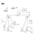
以下、図4を参照して本発明の一実施形態に係る移動端末機が動作できる通信システムについて説明する。 Hereinafter, a communication system capable of operating a mobile terminal according to an embodiment of the present invention will be described with reference to FIG.
通信システムは、異なる無線インタフェース及び/又は物理層を利用することもできる。例えば、通信システムにより利用可能な無線インタフェースは、周波数分割多元接続(Frequency Division Multiple Access; FDMA)、時分割多元接続(Time Division Multiple Access; TDMA)、符号分割多元接続(Code Division Multiple Access; CDMA)、汎用移動通信システム(Universal Mobile Telecommunications Systems; UMTS)(特に、LTE(Long Term Evolution))、移動通信グローバルシステム(Global System for Mobile Communications; GSM)などを含む。以下、説明の便宜上、CDMAに限定して説明するが、本発明をCDMA無線通信システムを含む全ての通信システムに適用できることは明らかである。 The communication system may also utilize different radio interfaces and / or physical layers. For example, the radio interfaces that can be used by the communication system include Frequency Division Multiple Access (FDMA), Time Division Multiple Access (TDMA), Code Division Multiple Access (Code Division C) Multiple Access (Code Division C) Multiple Access (FDMA). , Universal Mobile Telecommunication Systems (UMTS) (in particular, LTE (Long Term Evolution)), Mobile Communications Global Communications (GSM), etc. Hereinafter, for convenience of explanation, the description is limited to CDMA. However, it is apparent that the present invention can be applied to all communication systems including a CDMA wireless communication system.
図4に示すように、CDMA無線通信システムは、複数の移動端末機100と、複数の基地局(Base Station; BS)270と、複数の基地局制御部(Base Station Controller; BSC)275と、移動スイッチングセンタ(Mobile Switching Center; MSC)280とを含む。MSC280は、公衆交換電話網(Public Switched Telephone Network; PSTN)290に接続するように構成され、BSC275にも接続するように構成される。BSC275は、バックホールライン(backhaul line)を介してBS270に接続することができる。バックホールラインは、E1/T1、ATM、IP、PPP、フレームリレー、HDSL、ADSL、又はxDSLの少なくとも1つによって備えることができる。従って、複数のBSC275を図4に示すシステムに含めることができる。
As shown in FIG. 4, the CDMA radio communication system includes a plurality of
それぞれのBS270は、少なくとも1つのセクタを含み、それぞれのセクタは、全方向性アンテナ、又はBS270から放射状の特定方向を指向するアンテナを含むことができる。また、それぞれのセクタは、様々な形態のアンテナを2つ以上含むこともできる。それぞれのBS270は、複数の周波数割当をサポートするように構成され、各周波数割当は、特定スペクトル(例えば、1.25MHz、5MHzなど)を有する。
Each
セクタと周波数割当の交差はCDMAチャネルともいう。BS270は基地局送受信サブシステム(Base Station Transceiver Subsystem; BTS)ともいう。この場合、「基地局」とは、1つのBSC275と少なくとも1つのBS270を合わせたものをいう。また、基地局は「セルサイト」を示すこともできる。又は、特定BS270における複数のセクタのそれぞれをセルサイトということもできる。
The intersection of sector and frequency allocation is also called a CDMA channel. The
図4に示すように、放送送信部(Broadcasting Transmitter; BT)295は、システム内で動作する移動端末機100に放送信号を送信する。図1に示す放送受信モジュール111は、BT295により送信される放送信号を受信するために移動端末機100内に備えられる。
As shown in FIG. 4, a broadcast transmitting unit (BT) 295 transmits a broadcast signal to the
さらに、図4においては複数のGPS衛星300を示す。GPS衛星300は、複数の移動端末機100の少なくとも1つの移動端末機の位置把握をサポートする。図4には2つの衛星を示しているが、位置情報は2つ以下又は2つ以上の衛星により取得することもできる。図1に示す位置情報モジュール115は、所望の位置情報を取得するためにGPS衛星300と連動する。ここでは、GPS追跡技術だけでなく、位置を追跡できる全ての技術を用いて位置を追跡できる。また、GPS衛星300の少なくとも1つは、選択又は追加して衛星DMB伝送を担当できる。
Further, FIG. 4 shows a plurality of
無線通信システムが一般的に動作する過程で、BS270は多様な移動端末機100から逆方向リンク信号を受信する。ここで、移動端末機100は、呼接続中であるか、メッセージ送受信中であるか、又は他の通信動作を実行中である。特定BS270に受信された逆方向リンク信号のそれぞれは、特定BS270内で処理される。前記処理の結果生成されたデータは、接続されたBSC275に送信される。BSC275は、基地局270間のソフトハンドオフの組織化などの呼資源割当機能及び移動性管理機能を提供する。また、BSC275は前記受信したデータをMSC280に送信し、MSC280はPSTN290との接続のために追加的な伝送サービスを提供する。PSTN290はMSC280に接続し、MSC280はBSC275に接続し、BSC275は移動端末機100に順方向リンク信号を伝送するようにBS270を制御する。
During the general operation of the wireless communication system, the
本発明は、充電状況に応じて異なる充電方式について記述する。すなわち、移動端末機のバッテリ電源が所定レベル以下になると充電を行う方式の場合は、電力の浪費を抑えるために移動端末機で充電を要求及び中断できるようにし、充電に所定の制限がない方式の場合は、移動端末機が充電電源供給部(又は、充電器)付近に近づけば常に充電が行われるようにすることができる。 The present invention describes different charging schemes depending on the charging situation. In other words, in the case of a method of charging when the battery power of the mobile terminal is below a predetermined level, the mobile terminal can request and interrupt charging in order to suppress waste of power, and there is no predetermined restriction on charging. In this case, charging can be performed whenever the mobile terminal is close to the charging power supply unit (or the charger).
また、本発明は、課金されるか否かによって異なる充電メニューについて記述する。例えば、移動端末機を充電する際、個人的な場所にある充電電源供給部を使用する場合は、課金されないので、端末機はユーザに充電範囲、充電効率、及び充電状態のみを通知する。それに対して、公共の場所での充電の場合は、個人の充電電力ではないため課金されるので、端末機はユーザに充電するか否か、料金、充電量、及び充電状態などを通知する。 In addition, the present invention describes different charging menus depending on whether or not the user is charged. For example, when charging a mobile terminal, if a charging power supply unit in a personal place is used, no charge is made, so the terminal notifies the user only of the charging range, charging efficiency, and charging state. On the other hand, in the case of charging in a public place, since it is not personal charging power, it is charged, so the terminal notifies the user whether to charge, the charge, the amount of charge, the state of charge, and the like.
以下、課金されるか否かによってユーザが選択すべきメニューと充電方式についてより詳細に説明する。 Hereinafter, the menu and the charging method that should be selected by the user depending on whether or not the user is charged will be described in more detail.
本発明において、無線充電は、課金される充電(有料充電)と課金されない充電(無料充電)とに区分され、さらに移動端末機が要求する充電と充電電源供給部が一方的に提供する充電とに区分される。 In the present invention, wireless charging is classified into charged charging (charged charging) and non-charged charging (free charging), and charging requested by the mobile terminal and charging unilaterally provided by the charging power supply unit. It is divided into.
従って、本発明は、無線充電のタイプに応じてユーザに適切な充電メニューを提供し、ユーザの設定に応じて実際に無線充電を行う。前記充電メニューは、無線電力発生器、基地局、放送中継局、中継器(例えば、WIBRO、無線LAN)、インターネット共有機、若しくは人工衛星のいずれか1つから無線で充電電源を供給するためのメニュー、又は誘導結合若しくは容量結合により無線充電ユニットから充電電源を供給するためのメニューの全てを含むことが好ましい。 Therefore, the present invention provides an appropriate charging menu for the user according to the type of wireless charging, and actually performs wireless charging according to the user's setting. The charging menu is for supplying charging power wirelessly from any one of a wireless power generator, a base station, a broadcast relay station, a repeater (eg, WIBRO, wireless LAN), an Internet sharing device, or an artificial satellite. It is preferable to include all of the menu or the menu for supplying charging power from the wireless charging unit by inductive coupling or capacitive coupling.
図1に示す放送受信モジュール111及び移動通信モジュール112は、無線充電のためのマイクロ波信号を受信することができる。また、近距離通信モジュール114は、近くの無線充電装置から無線充電のためのマイクロ波信号を受信し、位置情報モジュール115は、特定の人工衛星から無線充電のためのマイクロ波信号を受信することができる。
The
無線通信部110は、充電電源供給部から無線充電のためのマイクロ波信号を受信し、そのマイクロ波信号を所定の電気信号に変換する役割を果たす。前記充電電源供給部は、無線電力発生器(又は、無線伝送ユニット)、基地局、放送中継局、中継器(例えば、WIBRO、無線LAN)、インターネット共有機、及び人工衛星を含むことが好ましい。
The
ユーザ入力部130は、ユーザが端末機の動作を制御し、無線充電のためのメニューを設定し、特定メニューで無線充電動作を制御するための入力データを発生する。ユーザ入力部130は、キーパッド、ドームスイッチ、タッチパッド(静圧/静電)、ジョグホイール、ジョグスイッチなどから構成できる。特に、タッチパッドが後述するディスプレイ部151とレイヤ構造をなす場合、これをタッチスクリーンという。
The
出力部150は、オーディオ信号、ビデオ信号、又はアラーム信号を出力するためのもので、ディスプレイ部151、音響出力モジュール152、及びアラーム部153などを含む。
The
ディスプレイ部151は、移動端末機100で処理される情報を表示する。例えば、移動端末機100が通話モードの場合は、通話に関するUI若しくはGUIを表示し、移動端末機100がテレビ電話モード又は撮影モードの場合は、撮影及び/若しくは受信した画像、又はUI、GUIを表示する。また、ディスプレイ部151は、無線充電時、ユーザの制御により充電方式、充電するか否か、料金、充電量、及び充電状態に関する様々な充電メニューを表示する。
The
音響出力モジュール152は、呼受信モード、通話モード、録音モード、音声認識モード、又は放送受信モードなどで、無線通信部110から受信するか、又はメモリ160に保存されたオーディオデータを出力する。また、音響出力モジュール152は、移動端末機100で実行される機能(例えば、呼信号受信音、メッセージ受信音など)と無線充電機能(充電するか否か、充電量、充電効率の変動、並びに充電の開始及び中断に関する通知)に関連する音響信号を出力する。このような音響出力モジュール152は、スピーカ、ブザーなどを含む。
The
また、アラーム部153は、移動端末機100の一般的なイベント発生を通知するための信号だけでなく、充電中に発生したイベントを通知するための信号をも出力する。移動端末機100で発生するイベントの例としては、呼信号受信、メッセージ受信、キー信号入力、充電要求(システムからの充電要求)、及び効率の変動などがある。アラーム部153は、オーディオ信号やビデオ信号以外に、他の形態でイベント発生を通知するための信号を出力することもできる。例えば、振動の形態で信号を出力することができる。アラーム部153は、呼信号を受信するか又はメッセージを受信した場合、これを通知するために振動を発生することができる。また、アラーム部153は、キー信号が入力された場合、キー信号の入力に対するフィードバックとして振動を発生することもできる。このような振動の発生により、ユーザはイベント発生を認知することができる。もちろん、イベント発生を通知するための信号は、ディスプレイ部151又は音響出力モジュール152により出力することもできる。
In addition, the alarm unit 153 outputs not only a signal for notifying a general event occurrence of the
メモリ160は、制御部180の処理及び制御のためのプログラムを保存することもでき、入出力されるデータ(例えば、充電メニュー、及び該当充電メニューでユーザが設定した充電範囲、充電時間、課金されるか否か、充電通知タイプ、送信ソースの選択など)の一時保存のための機能を実行することもできる。
The
また、制御部180は、音声通話、データ通信、テレビ電話などの移動端末機100の全般的な動作を制御すると共に、無線充電のための制御及び処理を行う。
In addition, the
電源供給部190(以下、バッテリという)は、制御部180の制御下で、供給された外部の電源、内部の電源を各構成要素に必要に応じて供給する部分であって、前記充電電源供給部から送信されたマイクロ波信号が最終的に充電される部分である。よって、移動端末機と充電電源供給部を結合して1つの無線充電装置を構成することができる。
The power supply unit 190 (hereinafter referred to as a battery) is a part that supplies the supplied external power supply and internal power supply to each component as necessary under the control of the
以下、このように構成された本発明による移動端末機の無線充電方法について図5〜図10を参照して説明する。ここで、無線充電は、課金されるか否かによって無料充電と有料充電とに区分される。 Hereinafter, a wireless charging method for a mobile terminal according to the present invention configured as described above will be described with reference to FIGS. Here, wireless charging is classified into free charging and paid charging depending on whether or not charging is performed.
1.課金されない充電(無料充電)
本発明において、課金されない充電とは、家や事務室などのように課金されない場所で行う充電をいう。前述したように、課金されない充電は、充電電源供給部が提供する充電と端末機の要求により行われる充電とに区分される。
1. Charge not charged (free charge)
In the present invention, non-charged charging refers to charging performed at a place where no charge is made, such as a house or an office. As described above, uncharged charging is classified into charging provided by the charging power supply unit and charging performed at the request of the terminal.
・充電電源供給部による無料充電
充電電源供給部は、無線で充電電源を供給する装置であり、無線電力発生器(又は、無線伝送ユニット)、基地局、放送中継局、中継器(例えば、WIBRO、無線LAN)、インターネット共有機、及び人工衛星を含む。
Free charge by the charging power supply unit The charging power supply unit is a device that supplies charging power wirelessly, and includes a wireless power generator (or wireless transmission unit), a base station, a broadcast relay station, a repeater (for example, WIBRO) , Wireless LAN), Internet sharing machine, and artificial satellite.
前記充電電源供給部は、移動端末機の接近を確認するアンテナを含み、前記アンテナにより移動端末機の接近が感知されると該当端末機に充電電源供給関連情報(例えば、プロバイダ、料金、充電するか否か)を提供し、前記移動端末機は、前記充電電源供給関連情報を所定のメニュー形態でユーザに通知する。 The charging power supply unit includes an antenna for confirming the approach of the mobile terminal. When the approach of the mobile terminal is detected by the antenna, the charging power supply related information (eg, provider, fee, charge) is charged to the terminal. The mobile terminal notifies the user of the charging power supply related information in a predetermined menu form.
よって、前記移動端末機の制御部は、バッテリ容量が所定値以下であるか否かを確認して所定値以下である場合、これをディスプレイ部に表示して、前記充電電源供給部から充電電源の供給を受けるか否かを選択させることにより、前記充電電源供給部から充電電源の供給を受ける。このような動作は課金される場合もほぼ同様に適用される。 Accordingly, the control unit of the mobile terminal checks whether or not the battery capacity is equal to or less than a predetermined value, and if the battery capacity is equal to or less than the predetermined value, displays it on the display unit and sends the charge power from the charge power supply unit. The charging power is supplied from the charging power supply unit. Such an operation is applied almost in the same manner when charged.
図5はシステムによる無料充電方法を示すフローチャートである。 FIG. 5 is a flowchart showing a free charge method by the system.
図5に示すように、充電電源供給部は、移動端末機を充電するために、常にマイクロ波信号(又は、電波)を出力する。移動端末機の制御部180は、ユーザが家や事務室に位置する場合、周期的にバッテリ電圧を確認して、バッテリ電圧と基準電圧とを比較する(S10、S11)。
As shown in FIG. 5, the charging power supply unit always outputs a microwave signal (or radio wave) in order to charge the mobile terminal. When the user is located in the house or office, the
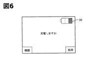
比較の結果、バッテリ電圧が基準電圧以下の場合、制御部180は、ディスプレイ部151の画面に、自動的に充電を行うように設定するメニュー(自動充電メニュー)、又はバッテリ充電が必要であるというメッセージを通知するメニュー(充電設定メニュー)のいずれか一方を表示する。
As a result of the comparison, when the battery voltage is equal to or lower than the reference voltage, the
すなわち、制御部180は、充電が必要な場合、ディスプレイ部151の画面に、自動的に充電を行うように設定するメニューを表示(図示せず)するか、又は無線充電を行うか否かを問い合わせるメッセージ、例えば「充電しますか。」を示すメニューを表示(図6参照)することにより、ユーザに現在充電が必要であることを通知する(S12)。このとき、ディスプレイ部151の画面には、バッテリ表示50と共に残量が所定の色で表示される。よって、ユーザは前記充電メニューで「確認」又は「取消」キーを押すことにより、自動充電を選択しておくか、又は充電を行うか否かを決定する。
That is, when charging is necessary, the
次に、制御部180は、バッテリ電圧が所定値以下の状態で自動充電に設定されている場合は、バッテリを自動的に充電するように制御し、バッテリ電圧が所定値以下の状態で充電を行うことを決定した場合は、無線通信部110により前記充電電源供給部から受信したマイクロ波信号を電気信号に変換してバッテリを充電させ(S13)、視覚又は聴覚的に通知メッセージを表示するように制御する。
Next, when the battery voltage is set to automatic charging when the battery voltage is equal to or lower than a predetermined value, the
充電が行われている間、制御部180は、現在ディスプレイ部151に表示されているバッテリ表示50内に充電状態を所定の色で表示し(S14)、充電効率が低下したり、移動端末機が移動して前記充電電源供給部の範囲から外れるなど、特定状況が発生すると、出力部150のディスプレイ部151、音響出力モジュール152、及びアラーム部153により、すなわち文字、音、又は振動を利用して該当状況をユーザに通知する。
While charging is being performed, the
充電が完了すると、制御部180は、バッテリ表示50内に満充電状態を所定の色で表示し、無線充電動作を全て終了する(S15)。
When the charging is completed, the
他の実施形態として、充電電源供給部による無料充電の場合、制御部180は、バッテリ電圧が基準電圧以下になると、図5に示す段階S12を行うことなく、直ちに段階S13を行うことができる。これはユーザの設定により適切に変更可能である。
As another embodiment, in the case of free charging by the charging power supply unit, the
・端末の要求による無料充電
図7は端末の要求による無料充電方法を示すフローチャートである。
Free Charge at Terminal Request FIG. 7 is a flowchart showing a free charge method at the terminal request.
図7に示すように、制御部180は、ユーザが家や事務室に位置する場合、周期的にバッテリ電圧を確認して、バッテリ電圧と基準電圧とを比較する(S20、S21)。
As shown in FIG. 7, when the user is located in a house or office, the
比較の結果、バッテリ電圧が基準電圧以下の場合、制御部180は、後述する段階S23に直ちに移行して充電電源供給部を感知するか、又は図8に示すように、ディスプレイ部151の画面(LCDウィンドウ又はタッチスクリーン)に充電メニュー、すなわち無線充電を行うか否かを問い合わせるメッセージ(「充電しますか。」)を表示して、ユーザに充電が必要であることを通知する(S22)。ここで、前記充電メニューを表示するか否か及び前記基準電圧のレベルはユーザが任意に設定可能である。すなわち、課金されない端末の要求による無線充電の場合は、前記充電メニューの表示は選択的に行われる。
As a result of the comparison, if the battery voltage is equal to or lower than the reference voltage, the
また、制御部180は、ディスプレイ部151の画面に、前記充電メニューと共に、現在のバッテリ残量をバッテリ表示50内に所定の色で表示させる。
In addition, the
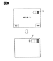
前記充電メニューが表示された場合、ユーザは「確認」又は「取消」キーを選択して充電を行うか否かを決定する。ここで、ユーザが確認キーを選択して無線充電を開始すると、制御部180は、所定の充電電源供給部を感知し、その感知された充電電源供給部に電力要求信号を送信する(S23、S24)。このとき、制御部180は、図8に示すように、バッテリ表示50の前方にアンテナ表示51を表示して充電電源供給部が感知されたことを示し、そのアンテナ線の数を利用して前記感知された充電電源供給部の充電効率を表示する。次に、無線通信部110は、制御部180の制御により、前記感知された充電電源供給部からマイクロ波信号を受信してバッテリを充電させる(S25)。
When the charging menu is displayed, the user selects a “confirm” or “cancel” key to determine whether to perform charging. Here, when the user selects a confirmation key and starts wireless charging, the
そして、充電状態を示す情報を表示する方法(音、文字、及びインジケータなど)はデフォルトで設定され、充電レベルは「満充電」に自動的に設定される。前記インジケータはバッテリ表示を示すことが好ましい。 And the method (sound, a character, an indicator, etc.) which displays the information which shows a charge condition is set by default, and a charge level is automatically set to "full charge." The indicator preferably indicates a battery indication.
無線充電が行われている間、制御部180は、バッテリ表示50内に充電状態を所定の色で表示し(S26、S27)、充電効率が低下したり、移動端末機が前記充電電源供給部の範囲から外れるなど、特定状況が発生すると、出力部150のディスプレイ部151、音響出力モジュール152、及びアラーム部153により、該当状況を文字、音、又は振動を利用してユーザに通知する。
While wireless charging is being performed, the
その後、バッテリが満充電されると、制御部180は、バッテリ表示50内に満充電状態を表示した後、無線通信部110により前記充電電源供給部にマイクロ波信号の送信中断を要求する信号を送信して、無線充電動作を全て終了する(S28、S29)。
After that, when the battery is fully charged, the
2.課金される充電(有料充電)
本発明において、課金される充電とは、課金される場所で行う充電をいう。この場合は、充電時間及び充電量が料金に大きく影響するため、ユーザに様々なメニューを提供することにより、ユーザが必要なだけバッテリを充電できるようにする。従って、課金される有料充電は、主に端末の要求による充電に該当する。ここで、制御部は、課金される充電の場合、充電するか否か、充電電源供給部の選択、充電量、及び充電状態通知方法の少なくとも1つの項目を制御する。
2. Charged charge (charged charge)
In the present invention, charged charging means charging performed at a charged place. In this case, since the charge time and the charge amount greatly affect the charge, the user can charge the battery as much as necessary by providing various menus to the user. Therefore, the charged charge to be charged mainly corresponds to the charge at the request of the terminal. Here, in the case of charged charging, the control unit controls at least one item of whether to charge, selection of a charging power supply unit, a charging amount, and a charging state notification method.
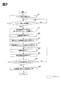
図9は端末の要求による有料充電方法を示すフローチャートであり、移動端末機が充電動作を開始する場合を示している。 FIG. 9 is a flowchart illustrating a charged charging method according to a request from a terminal, and illustrates a case where a mobile terminal starts a charging operation.
図9に示すように、制御部180は、周期的にバッテリ電圧を確認して、バッテリ電圧と基準電圧とを比較する(S30、S31)。
As shown in FIG. 9, the
比較の結果、バッテリ電圧が基準電圧以下の場合、制御部180は、少なくとも1つの充電器、すなわち充電電源供給部を感知し、ディスプレイ部151の画面(LCDウィンドウ又はタッチスクリーン)に無線充電のための詳細メニューを表示する(S33、S34)。
If the battery voltage is equal to or lower than the reference voltage as a result of the comparison, the
本発明は、他の実施形態として、図9に示すように、ディスプレイ部151の画面に充電メニュー、すなわち無線充電を行うか否かを問い合わせるメッセージ(「充電しますか。」)を表示して、ユーザに充電が必要であることを通知することができる(S32)。また、制御部180は、ディスプレイ部151の画面に、現在のバッテリ残量をバッテリ表示50内に所定の色で表示させる。ユーザは前記充電メニューで「確認」又は「取消」キーを選択して充電を行うか否かを決定する。
As another embodiment, as shown in FIG. 9, the present invention displays a charging menu, that is, a message for inquiring whether to perform wireless charging (“Do you charge?”) On the screen of the
前記無線充電のための詳細メニューは、充電状態を表示する方法を選択するための項目(音、文字、及びインジケータなど)、充電電源供給部を選択するための項目(電力が強力なもの、値段が安いもの、無料のもの;優先順位で選択)、及び充電量(充電レベル)を選択するための項目(使用料金基準、バッテリ残量基準、及び充電時間基準)を含み、その他の無線充電に必要な項目をも含む。 The detailed menu for wireless charging includes items for selecting a method for displaying the state of charge (sounds, characters, indicators, etc.), items for selecting a charging power supply unit (powerful ones, prices) , Including cheap items, free items (selected by priority), and items for selecting the amount of charge (charging level) (usage fee standard, remaining battery level criterion, and charging time criterion) for other wireless charging Includes necessary items.
一方、ユーザが充電メニューで充電電源供給部を予め設定した場合は、前記段階S34が前記段階S33より前に行われる。すなわち、前記段階S33で制御部180は充電メニューで予め設定した充電装置を感知する。
On the other hand, when the user presets the charging power supply unit in the charging menu, the step S34 is performed before the step S33. That is, in step S33, the
前記詳細メニューで所望の全ての項目が選択されると、ユーザは確認キーを押して無線充電を開始し、無線充電が開始されると、制御部180は前記選択された充電電源供給部に電力要求信号を送信する(S35)。このとき、制御部180は、図8に示すように、バッテリ表示50の前方にアンテナ表示51を表示して充電電源供給部が感知されたことを示し、そのアンテナ線の数を利用して前記感知された充電電源供給部の充電効率を表示する。次に、無線通信部110は、制御部180の制御により、前記感知された充電電源供給部からマイクロ波信号を受信してバッテリを充電させる(S36、S37)。
When all desired items are selected in the detailed menu, the user presses a confirmation key to start wireless charging. When wireless charging is started, the
無線充電が行われている間、制御部180は、充電状態を前記選択した方法(バッテリ残量、時間、料金など)で表示し(S38)、充電効率が低下したり、移動端末機が前記充電電源供給部の範囲から外れるなど、特定状況が発生すると、出力部150のディスプレイ部151、音響出力モジュール152、及びアラーム部153により、該当状況を文字、音、又は振動を利用してユーザに通知する。
While wireless charging is being performed, the
その後、制御部180は、バッテリが前記段階S34で設定した充電レベルまで充電されたか否かを比較して(S39)、所望の充電レベルまで充電されると、無線通信部110により前記充電電源供給部にマイクロ波信号の送信中断を要求する信号を送信して、無線充電動作を全て終了する(S40)。
Thereafter, the
以上の図9を参照して説明した実施形態においては、移動端末機が充電レベルに基づいて充電時期を判断しているが、これに限定されるものではなく、ユーザが所望の時期に直接充電動作を開始することもできる。 In the embodiment described with reference to FIG. 9 above, the mobile terminal determines the charging time based on the charging level. However, the present invention is not limited to this, and the user directly charges at a desired time. The operation can also be started.
図10は端末の要求による有料充電方法を示すフローチャートであり、ユーザが充電動作を開始する場合を示している。 FIG. 10 is a flowchart showing a charged charging method according to a request from the terminal, and shows a case where the user starts a charging operation.
ユーザが充電動作を開始する場合は、図10に示すように、図9の段階S30〜S33を行うことなく、直ちにユーザがメニューで無線充電のための詳細項目を選択する段階(S34)に移行する。すなわち、ユーザは無線充電を行うために、充電メニューを表示させた後、充電状態を表示する方法(音、文字、及びインジケータなど)、充電電源供給部(電力が強力なもの、値段が安いもの、無料のもの;優先順位で選択)、及び充電量(充電レベル)(使用料金、バッテリ残量、及び充電時間を基準に選択)などを選択する(S50)。 When the user starts the charging operation, as shown in FIG. 10, the process immediately proceeds to the step (S <b> 34) where the user selects a detailed item for wireless charging from the menu without performing steps S <b> 30 to S <b> 33 of FIG. 9. To do. In other words, in order to perform wireless charging, the user displays a charging menu and then displays a charging state (sounds, letters, indicators, etc.), a charging power supply unit (power is strong, and price is low) , Free one; selected according to priority), charge amount (charge level) (selected based on usage fee, remaining battery charge, and charge time), etc. (S50).
前記詳細メニューで所望の全ての項目が選択されると、ユーザは確認キーを押して無線充電を開始し、無線充電が開始されると、制御部180は前記選択された充電電源供給部に電力要求信号を送信する(S51)。このとき、制御部180は、図8に示すように、バッテリ表示50の前方にアンテナ表示51を表示して充電電源供給部が感知されたことを示し、そのアンテナ線の数を利用して前記感知された充電電源供給部の充電効率を表示する。次に、無線通信部110は、制御部180の制御により、前記感知された充電電源供給部からマイクロ波信号を受信してバッテリを充電させる(S52、S53)。
When all desired items are selected in the detailed menu, the user presses a confirmation key to start wireless charging. When wireless charging is started, the
無線充電が行われている間、制御部180は、充電状態を前記選択した方法(バッテリ残量、時間、料金など)で表示し(S54)、充電効率が低下したり、移動端末機が前記充電電源供給部の範囲から外れるなど、特定状況が発生すると、出力部150のディスプレイ部151、音響出力モジュール152、及びアラーム部153により、該当状況を文字、音、又は振動を利用してユーザに通知する。
While wireless charging is being performed, the
その後、制御部180は、バッテリが前記段階S40で設定した充電レベルまで充電されたか否かを比較して(S55)、所望の充電レベルまで充電されると、無線通信部110により前記充電電源供給部にマイクロ波信号の送信中断を要求する信号を送信して、無線充電動作を全て終了する(S56)。
Thereafter, the
このように本発明は、課金されるか否かによってユーザが選択すべきメニューを提供し、前記メニューでユーザが選択した項目に応じて無線充電を行うことにより、所望の量又は必要な金額だけバッテリを充電することができる。 As described above, the present invention provides a menu to be selected by the user depending on whether or not the user is charged, and performs wireless charging according to the item selected by the user in the menu, so that only a desired amount or a necessary amount is obtained. The battery can be charged.
本発明の一実施形態による移動端末機の無線充電方法は、プログラムが記録された媒体にコンピュータ可読コードとして実現できる。コンピュータ可読媒体は、コンピュータシステムで読み取り可能なデータが保存される全ての種類の記憶装置を含む。コンピュータ可読媒体の例としては、ROM、RAM、CD−ROM、磁気テープ、フロッピー(登録商標)ディスク、光データ記憶装置などがあり、搬送波(例えば、インターネットによる伝送)の形で実現されるものも含む。また、前記コンピュータは端末機の制御部180を含むこともできる。
The wireless charging method of a mobile terminal according to an embodiment of the present invention can be realized as a computer readable code on a medium in which a program is recorded. Computer-readable media includes all types of storage devices that can store data that can be read by a computer system. Examples of computer-readable media include ROM, RAM, CD-ROM, magnetic tape, floppy (registered trademark) disk, optical data storage device, etc., and those realized in the form of a carrier wave (for example, transmission over the Internet). Including. In addition, the computer may include a
本発明による無線充電用メニュー提供機能を有する移動端末機及びその無線充電方法は、前述した実施形態の構成と方法の適用に限定されるのではなく、各実施形態の全部又は一部を選択して組み合わせることにより様々な変形が可能である。 The mobile terminal having a function for providing a menu for wireless charging according to the present invention and the wireless charging method thereof are not limited to the application of the configuration and method of the above-described embodiment, but select all or a part of each embodiment. Various modifications are possible by combining them.
Claims (27)
充電メニュー及びその充電メニューの設定を保存するメモリと、
課金されるか否かによって無線充電のための充電メニューを提供し、その充電メニューの設定に応じて無線充電動作を制御する制御部と
を含むことを特徴とする移動端末機。 An output unit for outputting a wireless charging state;
A memory for storing the charging menu and the setting of the charging menu;
A mobile terminal comprising: a control unit that provides a charging menu for wireless charging according to whether or not charging is performed, and controls wireless charging operation according to the setting of the charging menu.
バッテリ残量が所定レベル以下である場合、自動充電メニューと充電設定メニューのいずれか一方が設定されているかを確認する段階と、
充電電源供給部から無線電力を受けて前記メニューの設定に応じてバッテリ充電を行う段階と
を含むことを特徴とする移動端末機の無線充電方法。 Check the remaining battery level,
When the remaining battery level is below a predetermined level, checking whether either the automatic charging menu or the charging setting menu is set,
Receiving a wireless power from a charging power supply unit and charging the battery according to the setting of the menu.
Applications Claiming Priority (2)
| Application Number | Priority Date | Filing Date | Title |
|---|---|---|---|
| KR1020070129355A KR101432590B1 (en) | 2007-12-12 | 2007-12-12 | Mobile terminal having menu providing function for radio charging and charging method therefor |
| KR10-2007-0129355 | 2007-12-12 |
Publications (2)
| Publication Number | Publication Date |
|---|---|
| JP2009148151A true JP2009148151A (en) | 2009-07-02 |
| JP5243204B2 JP5243204B2 (en) | 2013-07-24 |
Family
ID=40512394
Family Applications (1)
| Application Number | Title | Priority Date | Filing Date |
|---|---|---|---|
| JP2008298464A Expired - Fee Related JP5243204B2 (en) | 2007-12-12 | 2008-11-21 | Mobile terminal having wireless charging menu providing function and wireless charging method thereof |
Country Status (6)
| Country | Link |
|---|---|
| US (1) | US8198858B2 (en) |
| EP (1) | EP2071695B1 (en) |
| JP (1) | JP5243204B2 (en) |
| KR (1) | KR101432590B1 (en) |
| CN (1) | CN101459981B (en) |
| TW (1) | TWI442782B (en) |
Cited By (22)
| Publication number | Priority date | Publication date | Assignee | Title |
|---|---|---|---|---|
| JP2012110084A (en) * | 2010-11-15 | 2012-06-07 | Mitsubishi Motors Corp | Charging display device for electric vehicle |
| JP2012143091A (en) * | 2011-01-04 | 2012-07-26 | Kimitake Utsunomiya | Remotely and wirelessly driven charger |
| WO2012132929A1 (en) * | 2011-03-30 | 2012-10-04 | 日本写真印刷株式会社 | Power receiving device having touch panel and power transmission system for feeding power to power receiving device |
| JP2013511955A (en) * | 2009-11-17 | 2013-04-04 | クアルコム,インコーポレイテッド | Authorization-based wireless power reception |
| WO2013057786A1 (en) | 2011-10-18 | 2013-04-25 | トヨタ自動車株式会社 | Power feeding device, and power feeding method |
| WO2013076834A1 (en) | 2011-11-24 | 2013-05-30 | トヨタ自動車株式会社 | Power transmitting device, vehicle, and non-contact power transmitting/receiving system |
| WO2013118385A1 (en) * | 2012-02-10 | 2013-08-15 | ソニー株式会社 | Power receiving device and program |
| KR101356430B1 (en) | 2012-08-01 | 2014-02-03 | 한국과학기술원 | Method and apparatus for controlling charge of device |
| US8853995B2 (en) | 2009-06-12 | 2014-10-07 | Qualcomm Incorporated | Devices for conveying wireless power and methods of operation thereof |
| US8853889B2 (en) | 2010-09-08 | 2014-10-07 | Sony Corporation | Communication terminal apparatus and method for supplying terminal power source |
| JP2015006106A (en) * | 2013-06-24 | 2015-01-08 | Necカシオモバイルコミュニケーションズ株式会社 | Electric apparatus, charge control method, and program |
| JP2015008462A (en) * | 2013-06-20 | 2015-01-15 | ゴールデン ヴェスト マカオ コマーシャル オフショア リミテッド | Multifunctional mcu implementation method and multifunctional mcu |
| JP2015015746A (en) * | 2009-08-24 | 2015-01-22 | アクセス ビジネス グループ インターナショナル リミテッド ライアビリティ カンパニー | Radio power distribution and control system |
| JP2015032037A (en) * | 2013-07-31 | 2015-02-16 | キヤノン株式会社 | Network system, mobile terminal, information processing device, and control method |
| JP2015159720A (en) * | 2009-01-06 | 2015-09-03 | アクセス ビジネス グループ インターナショナル リミテッド ライアビリティ カンパニー | Power distribution method of wireless power |
| JP2017127061A (en) * | 2016-01-12 | 2017-07-20 | トヨタ自動車株式会社 | Electric vehicle |
| KR101785456B1 (en) * | 2011-04-25 | 2017-11-06 | 엘지전자 주식회사 | Apparatus and system for providing wireless power charge service |
| KR101789540B1 (en) * | 2011-03-21 | 2017-11-20 | 엘지전자 주식회사 | Method for Wirelessly charging battery, Wireless charger, and electronic device |
| JP2018164404A (en) * | 2017-06-12 | 2018-10-18 | キヤノン株式会社 | Power reception device, control method for power reception device, and program |
| US10559985B2 (en) | 2010-11-04 | 2020-02-11 | Canon Kabushiki Kaisha | Wireless power transfer system, control method of wireless power transfer system, wireless power transmitting apparatus, control method of wireless power transmitting apparatus, and storage medium |
| JP2020150645A (en) * | 2019-03-12 | 2020-09-17 | 日本電気株式会社 | Mobile device, server device, wireless power supply system, information presentation method, and program |
| JP2021509568A (en) * | 2017-12-29 | 2021-03-25 | エドゥクレンチ カンパニー リミテッドAdcrunch Co.,Ltd. | Charging circuit management method and system |
Families Citing this family (72)
| Publication number | Priority date | Publication date | Assignee | Title |
|---|---|---|---|---|
| CN101438477B (en) * | 2006-03-28 | 2013-04-10 | 京瓷株式会社 | Portable terminal and function operation control method |
| KR101474421B1 (en) * | 2007-11-23 | 2014-12-19 | 엘지전자 주식회사 | Mobile terminal having charging menu setting function and mutual charging method using the same |
| US20090240814A1 (en) * | 2008-03-18 | 2009-09-24 | Microsoft Corporation | Unified pairing for wireless devices |
| JP4544338B2 (en) * | 2008-04-28 | 2010-09-15 | ソニー株式会社 | Power transmission device, power reception device, power transmission method, program, and power transmission system |
| JP5258521B2 (en) * | 2008-11-14 | 2013-08-07 | トヨタ自動車株式会社 | Power supply system |
| USD611898S1 (en) | 2009-07-17 | 2010-03-16 | Lin Wei Yang | Induction charger |
| USD611900S1 (en) | 2009-07-31 | 2010-03-16 | Lin Wei Yang | Induction charger |
| USD611899S1 (en) | 2009-07-31 | 2010-03-16 | Lin Wei Yang | Induction charger |
| US8466660B2 (en) | 2009-11-06 | 2013-06-18 | Toyota Motor Engg. & Mfg. North America, Inc. | Wireless energy transfer antennas and energy charging systems |
| CN101707384A (en) * | 2009-11-25 | 2010-05-12 | 中兴通讯股份有限公司 | System and method compatible for wired charging and wireless charging |
| CN101777676B (en) * | 2010-01-06 | 2013-07-03 | 中兴通讯股份有限公司 | Method for wireless charge between mobile terminal equipment and mobile terminal |
| KR20110103294A (en) | 2010-03-12 | 2011-09-20 | 삼성전자주식회사 | Apparatus and method for performing wireless charging |
| US20120072753A1 (en) * | 2010-09-20 | 2012-03-22 | Bandrich, Inc. | Electronic system with router and charger functions, and method for operating the same |
| CN102013212B (en) * | 2010-09-28 | 2014-03-26 | 鸿富锦精密工业(深圳)有限公司 | Indication device and manufacturing method thereof and electronic device provided with same |
| EP2654177A4 (en) * | 2010-12-16 | 2014-06-25 | Lg Electronics Inc | Wireless power supply device, electronic device capable of receiving wireless power, and method for controlling transmission of wireless power |
| CN102572076B (en) * | 2010-12-23 | 2013-10-30 | 汉王科技股份有限公司 | Method and device for displaying charging state |
| KR101727495B1 (en) | 2010-12-28 | 2017-05-02 | 엘지전자 주식회사 | Mobile terminal |
| US10043223B2 (en) * | 2010-12-30 | 2018-08-07 | International Business Machines Corporation | Managing power distribution |
| KR20120102446A (en) | 2011-03-08 | 2012-09-18 | 삼성전자주식회사 | Mobile terminal, method for controlling wireless charge thereof, and wireless charging system thereof |
| CN102752439A (en) * | 2011-04-21 | 2012-10-24 | 汉王科技股份有限公司 | Method and device for dynamically displaying charging effect |
| US20120290470A1 (en) * | 2011-05-11 | 2012-11-15 | Samsung Electro-Mechanics Company, Ltd. | Payment systems and methods for providing wireless power transfer |
| KR102000561B1 (en) | 2011-05-17 | 2019-10-01 | 삼성전자주식회사 | Apparatus and method for controlling wireless power transmission |
| KR101830737B1 (en) * | 2011-05-17 | 2018-04-04 | 엘지전자 주식회사 | Mobile terminal and method for controlling the same |
| KR101847914B1 (en) * | 2011-05-19 | 2018-04-12 | 엘지전자 주식회사 | Mobile terminal and operating method thereof |
| KR20120135885A (en) * | 2011-06-07 | 2012-12-17 | 삼성전자주식회사 | Wireless power transmitting/receiving system comprising transmitter and receiver, two-way communication method between the transmitter and the receiver, and the apparatuses |
| US9545854B2 (en) * | 2011-06-13 | 2017-01-17 | General Electric Company | System and method for controlling and powering a vehicle |
| US9065922B2 (en) * | 2011-06-29 | 2015-06-23 | Blackberry Limited | System and method for providing low battery notifications on mobile devices |
| KR101605353B1 (en) | 2011-10-14 | 2016-03-22 | 엠파이어 테크놀로지 디벨롭먼트 엘엘씨 | Mobile terminal, power transfer system and computer-readable storage medium |
| KR101246841B1 (en) * | 2011-10-26 | 2013-03-28 | 엘지전자 주식회사 | Mobile terminal, charging apparatus and controlling method for charging apparatus |
| KR101864619B1 (en) * | 2011-10-27 | 2018-06-07 | 엘지전자 주식회사 | Mobile terminal and control method thereof |
| CN103167588A (en) * | 2011-12-13 | 2013-06-19 | 中兴通讯股份有限公司 | Wireless charging method, wireless base station, terminal and system |
| JP5696716B2 (en) * | 2012-02-28 | 2015-04-08 | 横河電機株式会社 | Wireless communication system, wireless communication method, and wireless access point device |
| KR101196552B1 (en) | 2012-03-23 | 2012-11-01 | (주) 씨아이디티 | Secondary coil of Receiver for Non-Contact Charging System |
| KR101428000B1 (en) * | 2012-04-20 | 2014-08-08 | 전자부품연구원 | Method and system for multi contactless charging |
| KR101844226B1 (en) * | 2012-05-14 | 2018-05-14 | 엘지전자 주식회사 | Wireless charger which can display charable area and controlling method thereof |
| KR101428163B1 (en) * | 2012-05-25 | 2014-08-07 | 엘지이노텍 주식회사 | Apparatus and method thereof for indicating a terminal status |
| US9632969B2 (en) * | 2012-08-07 | 2017-04-25 | Google Inc. | Systems and methods for managing a wireless connection between a computing device and a peripheral module |
| KR101396311B1 (en) * | 2012-09-06 | 2014-05-22 | 주식회사 메이드포 | Wireless Electric Power transmission system with sensing means of transmission efficency |
| CN102904301B (en) * | 2012-10-08 | 2015-12-16 | 中兴通讯股份有限公司 | The wireless charging method of terminal and device |
| KR102006488B1 (en) * | 2012-11-14 | 2019-10-01 | 엘지전자 주식회사 | Mobile terminal |
| JP5495407B1 (en) * | 2012-12-21 | 2014-05-21 | パナソニック株式会社 | Electronic device, charger and electronic device system |
| KR102049075B1 (en) * | 2013-01-08 | 2019-11-26 | 삼성전자주식회사 | Method and apparatus for displaying information on wireless charging pad in electronic device |
| CN104143855A (en) * | 2013-05-07 | 2014-11-12 | 冠捷投资有限公司 | Power supply unit capable of achieving zero stand-by power consumption |
| GB2518128B (en) * | 2013-06-20 | 2021-02-10 | Nokia Technologies Oy | Charging rechargeable apparatus |
| JP6245859B2 (en) * | 2013-06-26 | 2017-12-13 | キヤノン株式会社 | Power transmission device, power transmission device control method, and program |
| JP6254781B2 (en) * | 2013-06-28 | 2017-12-27 | キヤノン株式会社 | Information processing apparatus, information processing system, control method, and program |
| CN103414833B (en) * | 2013-08-30 | 2016-02-03 | 贝壳网际(北京)安全技术有限公司 | Mobile terminal and electric quantity display method and device thereof |
| CN104423790B (en) * | 2013-09-10 | 2017-11-24 | 联想(北京)有限公司 | The method and electronic equipment of a kind of information processing |
| CN104638704B (en) * | 2013-11-13 | 2019-06-18 | 深圳富泰宏精密工业有限公司 | Wireless charging device and its application method |
| CN103607026A (en) * | 2013-11-27 | 2014-02-26 | 上海电器科学研究院 | Intelligent switch with wireless charging function and charging method |
| US20150326058A1 (en) * | 2014-05-07 | 2015-11-12 | Htc Corporation | Electronic Device for Handling Sharing of Communication Hardware in Wireless Charging System |
| KR20160050577A (en) * | 2014-10-30 | 2016-05-11 | 삼성전자주식회사 | Display apparatus and control method thereof |
| DE102015006677A1 (en) * | 2015-05-22 | 2016-11-24 | Audi Ag | Charging a mobile terminal in a motor vehicle by means of wireless power transmission |
| CN104821631B (en) * | 2015-05-22 | 2018-01-02 | 上海斐讯数据通信技术有限公司 | User equipment, power supply unit, charging base and the charging system formed |
| US10627499B2 (en) * | 2015-05-22 | 2020-04-21 | Witricity Corporation | Methods and apparatus utilizing digital signal processing of ultra wide band radar signals for living object detection in wireless power transfer applications |
| KR102469570B1 (en) * | 2015-09-08 | 2022-11-22 | 삼성전자주식회사 | Electronic apparatus and operating method thereof |
| US10283985B2 (en) * | 2016-05-25 | 2019-05-07 | Lenovo (Singapore) Pte. Ltd. | Systems and methods to determine time at which battery is to be charged |
| CN106101389A (en) * | 2016-05-30 | 2016-11-09 | 珠海市魅族科技有限公司 | State information display method and device |
| WO2017209630A1 (en) | 2016-06-01 | 2017-12-07 | Powerbyproxi Limited | A powered joint with wireless transfer |
| KR20180037473A (en) * | 2016-10-04 | 2018-04-12 | 삼성전자주식회사 | Mobile payment method, electronic device and external payment device therefor |
| CN108604805B (en) | 2016-11-15 | 2021-01-29 | 华为技术有限公司 | Charging method and related equipment |
| US10951043B2 (en) * | 2017-06-04 | 2021-03-16 | Apple Inc. | Multi-device charging user interface |
| US9972037B1 (en) * | 2017-06-06 | 2018-05-15 | T-Mobile Usa, Inc. | Systems and methods for authorization and billing of users for wireless charging |
| US9800719B1 (en) * | 2017-07-11 | 2017-10-24 | Premergy, Inc. | Systems and methods for managing power for a mobile device |
| CN107658922A (en) * | 2017-09-12 | 2018-02-02 | 六安市华海电子器材科技有限公司 | A kind of base station being used for electronic equipment charging |
| KR102458690B1 (en) * | 2018-04-04 | 2022-10-25 | 삼성전자주식회사 | Electronic device having wireless charging module and flexible display |
| CN108638893B (en) * | 2018-05-18 | 2021-07-16 | 云南电网有限责任公司电力科学研究院 | Unmanned aerial vehicle charging system based on transmission tower |
| TWI665842B (en) * | 2018-06-13 | 2019-07-11 | 金碳洁股份有限公司 | Electricity management system of wireless charging and method thereof |
| US11710977B2 (en) * | 2021-03-11 | 2023-07-25 | Duracell U.S. Operations, Inc. | Integrated monitoring charging efficiency of a rechargeable device via a power bank |
| US11502528B2 (en) | 2021-03-11 | 2022-11-15 | Duracell U.S. Operations, Inc. | Integrated determination of charges remaining via a power bank |
| US11668757B2 (en) | 2021-03-11 | 2023-06-06 | Duracell U.S. Operations, Inc. | Integrated monitoring capacity of a power bank battery and devices charged therewith |
| WO2023239037A1 (en) * | 2022-06-10 | 2023-12-14 | 삼성전자 주식회사 | Electronic device and method for wirelessly transmitting or receiving power |
Citations (13)
| Publication number | Priority date | Publication date | Assignee | Title |
|---|---|---|---|---|
| JPH09297166A (en) * | 1996-03-08 | 1997-11-18 | Sony Corp | Electronic equipment with battery residual capacity display function, and method of displaying battery residual capacity |
| JPH10224995A (en) * | 1997-02-10 | 1998-08-21 | Nec Corp | Portable electronic apparatus incorporating battery pack and secondary battery |
| US6501949B1 (en) * | 1999-12-14 | 2002-12-31 | Ericsson Inc. | Acquisition of mobile station power source capacity levels in a wireless communications network |
| WO2004025805A1 (en) * | 2002-09-12 | 2004-03-25 | Mitsubishi Denki Kabushiki Kaisha | Receiving device, display device, power supply system, display system, and receiving method |
| JP2004246518A (en) * | 2003-02-13 | 2004-09-02 | Toyota Motor Corp | Radio power receiving device and energy supply facility |
| JP2005501456A (en) * | 2001-08-24 | 2005-01-13 | ユナイテッド パーセル サービス オブ アメリカ インコーポレイテッド | Portable data acquisition and management system and related apparatus and method |
| JP2005116531A (en) * | 2003-10-07 | 2005-04-28 | Akg Acoustics Gmbh | Battery drive device |
| JP2005222171A (en) * | 2004-02-03 | 2005-08-18 | Nec Access Technica Ltd | Cellular phone set |
| US20060284593A1 (en) * | 2005-06-21 | 2006-12-21 | Nagy Louis L | Wireless battery charging system and method |
| JP2006353042A (en) * | 2005-06-17 | 2006-12-28 | Ntt Docomo Inc | Power transmitting apparatus, power receiving apparatus, authentication/account proxy apparatus, charging system, power transmitting method, power receiving method, charging method |
| US20070060100A1 (en) * | 2005-09-14 | 2007-03-15 | Telemac Corporation | Systems and methods for mobile station service control |
| JP2007129658A (en) * | 2005-11-07 | 2007-05-24 | Sony Ericsson Mobilecommunications Japan Inc | Portable terminal device and power exchange method |
| JP2007288940A (en) * | 2006-04-18 | 2007-11-01 | Toshiba Corp | Charge service system, charger, and charge service providing method |
Family Cites Families (5)
| Publication number | Priority date | Publication date | Assignee | Title |
|---|---|---|---|---|
| US6522361B2 (en) * | 1996-03-08 | 2003-02-18 | Sony Corporation | Electronic apparatus having the function of displaying the battery residual quantity and method for displaying the battery residual quantity |
| US7068991B2 (en) * | 1997-05-09 | 2006-06-27 | Parise Ronald J | Remote power recharge for electronic equipment |
| JP2004222457A (en) * | 2003-01-16 | 2004-08-05 | Sony Corp | Charging system, portable electronic equipment, apparatus and method for charging, and apparatus and method for central control |
| CN1529182A (en) * | 2003-10-01 | 2004-09-15 | 复旦大学 | Electricity-quantity identification of active radio-frequency identification card cell and charging method thereof |
| KR100595613B1 (en) * | 2003-11-14 | 2006-06-30 | 엘지전자 주식회사 | Battery charge control method for mobile station having battery charger |
-
2007
- 2007-12-12 KR KR1020070129355A patent/KR101432590B1/en not_active IP Right Cessation
-
2008
- 2008-11-21 TW TW097145134A patent/TWI442782B/en not_active IP Right Cessation
- 2008-11-21 JP JP2008298464A patent/JP5243204B2/en not_active Expired - Fee Related
- 2008-12-04 EP EP08021075.0A patent/EP2071695B1/en not_active Not-in-force
- 2008-12-12 US US12/333,677 patent/US8198858B2/en not_active Expired - Fee Related
- 2008-12-12 CN CN2008101867348A patent/CN101459981B/en not_active Expired - Fee Related
Patent Citations (13)
| Publication number | Priority date | Publication date | Assignee | Title |
|---|---|---|---|---|
| JPH09297166A (en) * | 1996-03-08 | 1997-11-18 | Sony Corp | Electronic equipment with battery residual capacity display function, and method of displaying battery residual capacity |
| JPH10224995A (en) * | 1997-02-10 | 1998-08-21 | Nec Corp | Portable electronic apparatus incorporating battery pack and secondary battery |
| US6501949B1 (en) * | 1999-12-14 | 2002-12-31 | Ericsson Inc. | Acquisition of mobile station power source capacity levels in a wireless communications network |
| JP2005501456A (en) * | 2001-08-24 | 2005-01-13 | ユナイテッド パーセル サービス オブ アメリカ インコーポレイテッド | Portable data acquisition and management system and related apparatus and method |
| WO2004025805A1 (en) * | 2002-09-12 | 2004-03-25 | Mitsubishi Denki Kabushiki Kaisha | Receiving device, display device, power supply system, display system, and receiving method |
| JP2004246518A (en) * | 2003-02-13 | 2004-09-02 | Toyota Motor Corp | Radio power receiving device and energy supply facility |
| JP2005116531A (en) * | 2003-10-07 | 2005-04-28 | Akg Acoustics Gmbh | Battery drive device |
| JP2005222171A (en) * | 2004-02-03 | 2005-08-18 | Nec Access Technica Ltd | Cellular phone set |
| JP2006353042A (en) * | 2005-06-17 | 2006-12-28 | Ntt Docomo Inc | Power transmitting apparatus, power receiving apparatus, authentication/account proxy apparatus, charging system, power transmitting method, power receiving method, charging method |
| US20060284593A1 (en) * | 2005-06-21 | 2006-12-21 | Nagy Louis L | Wireless battery charging system and method |
| US20070060100A1 (en) * | 2005-09-14 | 2007-03-15 | Telemac Corporation | Systems and methods for mobile station service control |
| JP2007129658A (en) * | 2005-11-07 | 2007-05-24 | Sony Ericsson Mobilecommunications Japan Inc | Portable terminal device and power exchange method |
| JP2007288940A (en) * | 2006-04-18 | 2007-11-01 | Toshiba Corp | Charge service system, charger, and charge service providing method |
Cited By (38)
| Publication number | Priority date | Publication date | Assignee | Title |
|---|---|---|---|---|
| JP2015159720A (en) * | 2009-01-06 | 2015-09-03 | アクセス ビジネス グループ インターナショナル リミテッド ライアビリティ カンパニー | Power distribution method of wireless power |
| US8853995B2 (en) | 2009-06-12 | 2014-10-07 | Qualcomm Incorporated | Devices for conveying wireless power and methods of operation thereof |
| US9350202B2 (en) | 2009-08-24 | 2016-05-24 | Access Business Group International Llc | Wireless power distribution and control system |
| CN107086609A (en) * | 2009-08-24 | 2017-08-22 | 捷通国际有限公司 | Physics and virtual identifying in wireless power network |
| JP2015015746A (en) * | 2009-08-24 | 2015-01-22 | アクセス ビジネス グループ インターナショナル リミテッド ライアビリティ カンパニー | Radio power distribution and control system |
| US10277070B2 (en) | 2009-08-24 | 2019-04-30 | Philips Ip Ventures B.V. | Wireless power distribution and control system |
| US9502909B2 (en) | 2009-11-17 | 2016-11-22 | Qualcomm Incorporated | Power management for electronic devices |
| KR101779228B1 (en) * | 2009-11-17 | 2017-09-18 | 퀄컴 인코포레이티드 | Authorized based receipt of wireless power |
| JP2013511954A (en) * | 2009-11-17 | 2013-04-04 | クアルコム,インコーポレイテッド | Power management for electronic devices |
| JP2013511955A (en) * | 2009-11-17 | 2013-04-04 | クアルコム,インコーポレイテッド | Authorization-based wireless power reception |
| JP2014168378A (en) * | 2009-11-17 | 2014-09-11 | Qualcomm Inc | Devices for providing wireless charging information, wireless power receiving devices, methods of providing wireless charger information, methods of selecting wireless charging information, electronic devices for providing wireless charger information, and computer readable recording media |
| JP2014209845A (en) * | 2009-11-17 | 2014-11-06 | クアルコム,インコーポレイテッド | Authorized based receipt of wireless power |
| US9680313B2 (en) | 2009-11-17 | 2017-06-13 | Qualcomm Incorporated | Authorized based receipt of wireless power |
| US8853889B2 (en) | 2010-09-08 | 2014-10-07 | Sony Corporation | Communication terminal apparatus and method for supplying terminal power source |
| US9419471B2 (en) | 2010-09-08 | 2016-08-16 | Sony Corporation | Communication terminal apparatus and method for supplying terminal power source |
| US10559985B2 (en) | 2010-11-04 | 2020-02-11 | Canon Kabushiki Kaisha | Wireless power transfer system, control method of wireless power transfer system, wireless power transmitting apparatus, control method of wireless power transmitting apparatus, and storage medium |
| JP2012110084A (en) * | 2010-11-15 | 2012-06-07 | Mitsubishi Motors Corp | Charging display device for electric vehicle |
| JP2012143091A (en) * | 2011-01-04 | 2012-07-26 | Kimitake Utsunomiya | Remotely and wirelessly driven charger |
| KR101789540B1 (en) * | 2011-03-21 | 2017-11-20 | 엘지전자 주식회사 | Method for Wirelessly charging battery, Wireless charger, and electronic device |
| JP2012213251A (en) * | 2011-03-30 | 2012-11-01 | Nissha Printing Co Ltd | Power reception device having touch panel, and power transmission system for feeding power reception device |
| WO2012132929A1 (en) * | 2011-03-30 | 2012-10-04 | 日本写真印刷株式会社 | Power receiving device having touch panel and power transmission system for feeding power to power receiving device |
| KR101785456B1 (en) * | 2011-04-25 | 2017-11-06 | 엘지전자 주식회사 | Apparatus and system for providing wireless power charge service |
| US9254756B2 (en) | 2011-10-18 | 2016-02-09 | Toyota Jidosha Kabushiki Kaisha | Power supply device and power supply method |
| WO2013057786A1 (en) | 2011-10-18 | 2013-04-25 | トヨタ自動車株式会社 | Power feeding device, and power feeding method |
| US10513191B2 (en) | 2011-11-24 | 2019-12-24 | Toyota Jidosha Kabushiki Kaisha | Electric power transmission device, vehicle, and non-contact electric power transmission and reception system |
| WO2013076834A1 (en) | 2011-11-24 | 2013-05-30 | トヨタ自動車株式会社 | Power transmitting device, vehicle, and non-contact power transmitting/receiving system |
| US9802497B2 (en) | 2011-11-24 | 2017-10-31 | Toyota Jidosha Kabushiki Kaisha | Electric power transmission device, vehicle, and non-contact electric power transmission and reception system |
| JPWO2013118385A1 (en) * | 2012-02-10 | 2015-05-11 | ソニー株式会社 | Power receiving device and program |
| WO2013118385A1 (en) * | 2012-02-10 | 2013-08-15 | ソニー株式会社 | Power receiving device and program |
| KR101356430B1 (en) | 2012-08-01 | 2014-02-03 | 한국과학기술원 | Method and apparatus for controlling charge of device |
| JP2015008462A (en) * | 2013-06-20 | 2015-01-15 | ゴールデン ヴェスト マカオ コマーシャル オフショア リミテッド | Multifunctional mcu implementation method and multifunctional mcu |
| JP2015006106A (en) * | 2013-06-24 | 2015-01-08 | Necカシオモバイルコミュニケーションズ株式会社 | Electric apparatus, charge control method, and program |
| JP2015032037A (en) * | 2013-07-31 | 2015-02-16 | キヤノン株式会社 | Network system, mobile terminal, information processing device, and control method |
| JP2017127061A (en) * | 2016-01-12 | 2017-07-20 | トヨタ自動車株式会社 | Electric vehicle |
| JP2018164404A (en) * | 2017-06-12 | 2018-10-18 | キヤノン株式会社 | Power reception device, control method for power reception device, and program |
| JP2021509568A (en) * | 2017-12-29 | 2021-03-25 | エドゥクレンチ カンパニー リミテッドAdcrunch Co.,Ltd. | Charging circuit management method and system |
| JP2020150645A (en) * | 2019-03-12 | 2020-09-17 | 日本電気株式会社 | Mobile device, server device, wireless power supply system, information presentation method, and program |
| JP7225953B2 (en) | 2019-03-12 | 2023-02-21 | 日本電気株式会社 | Mobile device, server device, wireless power supply system, information presentation method, and program |
Also Published As
| Publication number | Publication date |
|---|---|
| JP5243204B2 (en) | 2013-07-24 |
| EP2071695A3 (en) | 2013-07-17 |
| KR101432590B1 (en) | 2014-08-21 |
| CN101459981B (en) | 2013-07-24 |
| EP2071695B1 (en) | 2016-03-30 |
| US20090156268A1 (en) | 2009-06-18 |
| TWI442782B (en) | 2014-06-21 |
| US8198858B2 (en) | 2012-06-12 |
| EP2071695A2 (en) | 2009-06-17 |
| TW200943988A (en) | 2009-10-16 |
| KR20090062224A (en) | 2009-06-17 |
| CN101459981A (en) | 2009-06-17 |
Similar Documents
| Publication | Publication Date | Title |
|---|---|---|
| JP5243204B2 (en) | Mobile terminal having wireless charging menu providing function and wireless charging method thereof | |
| JP4838294B2 (en) | Contactless charging device having charging information display function and charging method thereof | |
| US8575890B2 (en) | Mobile terminal having recharge menu setting function and inter-recharging method using the same | |
| JP4629745B2 (en) | Event display method and apparatus for mobile terminal | |
| US8174232B2 (en) | Solar charging apparatus and method for a mobile communication terminal | |
| EP2438794B1 (en) | Dual sim mobile terminal and operating method thereof | |
| KR101467767B1 (en) | Terminal and method of performing instant messaging service therein | |
| EP2658080B1 (en) | Mobile terminal and controlling method thereof | |
| US8411164B2 (en) | Mobile terminal and method for automatic geotagging | |
| KR20110036464A (en) | Dual sim mobile terminal and operating method thereof | |
| US20100169397A1 (en) | Mobile terminal and unit converting method thereof | |
| KR101397012B1 (en) | Terminal and method of setting service for data communication therein | |
| KR101404750B1 (en) | Apparatus and method for controlling contactless charging in mobile terminal | |
| KR101501999B1 (en) | Mobile terminal and charging alarm method for battery thereof | |
| KR101604680B1 (en) | Mobile terminal and method for controlling the same | |
| KR101405940B1 (en) | Communication terminal and method of transmitting message thereof | |
| KR101437978B1 (en) | Mobile terminal and status management method thereof | |
| KR101435819B1 (en) | Communication terminal and method of controlling operation therein | |
| KR101490241B1 (en) | Mobile terminal and method for controlling the same | |
| KR101495163B1 (en) | Mobile communication terminal having receiving call rejecting function and rejecting method therefor | |
| KR20090064855A (en) | A mobile terminal and a data tranferring method using the same | |
| KR20090062640A (en) | Communication device and method of outputting data therein | |
| KR101521926B1 (en) | Mobile terminal and solar energy charging method thereof | |
| KR101520657B1 (en) | Mobile terminal and method of using service therein | |
| KR101387511B1 (en) | Portable terminal and method of controlling broadcasting outputting thereof |
Legal Events
| Date | Code | Title | Description |
|---|---|---|---|
| A621 | Written request for application examination |
Free format text: JAPANESE INTERMEDIATE CODE: A621 Effective date: 20110902 |
|
| A131 | Notification of reasons for refusal |
Free format text: JAPANESE INTERMEDIATE CODE: A131 Effective date: 20121206 |
|
| A521 | Request for written amendment filed |
Free format text: JAPANESE INTERMEDIATE CODE: A523 Effective date: 20130227 |
|
| TRDD | Decision of grant or rejection written | ||
| A01 | Written decision to grant a patent or to grant a registration (utility model) |
Free format text: JAPANESE INTERMEDIATE CODE: A01 Effective date: 20130318 |
|
| A61 | First payment of annual fees (during grant procedure) |
Free format text: JAPANESE INTERMEDIATE CODE: A61 Effective date: 20130404 |
|
| FPAY | Renewal fee payment (event date is renewal date of database) |
Free format text: PAYMENT UNTIL: 20160412 Year of fee payment: 3 |
|
| R150 | Certificate of patent or registration of utility model |
Free format text: JAPANESE INTERMEDIATE CODE: R150 Ref document number: 5243204 Country of ref document: JP Free format text: JAPANESE INTERMEDIATE CODE: R150 |
|
| R250 | Receipt of annual fees |
Free format text: JAPANESE INTERMEDIATE CODE: R250 |
|
| R250 | Receipt of annual fees |
Free format text: JAPANESE INTERMEDIATE CODE: R250 |
|
| R250 | Receipt of annual fees |
Free format text: JAPANESE INTERMEDIATE CODE: R250 |
|
| LAPS | Cancellation because of no payment of annual fees |