WO2013115357A1 - 電子機器及び入力方法 - Google Patents
電子機器及び入力方法 Download PDFInfo
- Publication number
- WO2013115357A1 WO2013115357A1 PCT/JP2013/052344 JP2013052344W WO2013115357A1 WO 2013115357 A1 WO2013115357 A1 WO 2013115357A1 JP 2013052344 W JP2013052344 W JP 2013052344W WO 2013115357 A1 WO2013115357 A1 WO 2013115357A1
- Authority
- WO
- WIPO (PCT)
- Prior art keywords
- noise
- motion
- movement
- data
- electronic device
- Prior art date
- Legal status (The legal status is an assumption and is not a legal conclusion. Google has not performed a legal analysis and makes no representation as to the accuracy of the status listed.)
- Ceased
Links
Images




Classifications
-
- G—PHYSICS
- G06—COMPUTING OR CALCULATING; COUNTING
- G06F—ELECTRIC DIGITAL DATA PROCESSING
- G06F1/00—Details not covered by groups G06F3/00 - G06F13/00 and G06F21/00
- G06F1/16—Constructional details or arrangements
- G06F1/1613—Constructional details or arrangements for portable computers
- G06F1/1633—Constructional details or arrangements of portable computers not specific to the type of enclosures covered by groups G06F1/1615 - G06F1/1626
- G06F1/1684—Constructional details or arrangements related to integrated I/O peripherals not covered by groups G06F1/1635 - G06F1/1675
- G06F1/1694—Constructional details or arrangements related to integrated I/O peripherals not covered by groups G06F1/1635 - G06F1/1675 the I/O peripheral being a single or a set of motion sensors for pointer control or gesture input obtained by sensing movements of the portable computer
Definitions
- the present invention relates to an electronic device and an input method. This application claims priority based on Japanese Patent Application No. 2012-22379 for which it applied on February 3, 2012, and uses the content here.
- Patent Document 1 is known as an electronic device such as a mobile phone or a personal digital assistant provided with a three-axis acceleration sensor or the like.
- An electronic device as shown in Patent Document 1 has a motion interface that uses the movement of its own apparatus as an interface by detecting the movement of the own apparatus (main body) with a three-axis acceleration sensor.
- An object of one embodiment of the present invention is to provide an electronic device and an input method that can prevent input due to unintended movement of a user in an electronic device that uses the movement of the device (main body) as an interface.
- One embodiment of the present invention includes an operation storage unit that stores reference data for movement of the main body for executing each function, a noise storage unit that stores movement data that becomes noise, and motion detection that detects movement of the main body. And the movement of the main body detected by the movement detection unit include the movement that becomes the noise stored in the noise storage unit, the movement that becomes the noise is removed from the detected movement of the main body
- a noise removing unit that generates motion data
- an execution control unit that determines a function to be executed based on the motion data generated by the noise removing unit and the reference data stored in the operation storage unit;
- An electronic device comprising:
- FIG. 1 is a block diagram showing a functional configuration of an electronic device (main body) 100 according to the first embodiment of the present invention.
- the electronic device 100 is a portable information terminal such as a mobile phone, a smartphone, or a digital camera.
- Electronic device 100 has a normal mode and a boarding mode.
- Electronic device 100 includes a control unit 111, a storage unit 112, a motion detection unit 113, a contact detection unit 114, a display unit 115, and a speaker 116.
- the motion detection unit 113 includes a three-axis acceleration sensor and the like, and detects the movement of the casing (main body) of the electronic device 100 in the XYZ orthogonal coordinate system when the device is moved by the user, for example.
- the gravity direction is Y in the XYZ orthogonal coordinate system.
- a plane orthogonal to the Y direction is defined as an XZ plane, and directions orthogonal to the XZ plane are defined as an X direction and a Z direction, respectively.
- the Y direction is referred to as a vertical direction
- the X direction is referred to as a horizontal direction.
- the contact detection unit 114 is installed on the side of the housing of the electronic device 100 with respect to the surface on which the display surface of the display unit 115 is installed, and detects the presence / absence of contact and the contact position.
- the display unit 115 is, for example, a liquid crystal display panel or an organic EL panel, and displays an image or the like.
- a touch panel (not shown) is provided on the display surface of the display unit 115.
- the contact detection unit 114 and the touch panel are operation units that switch the mode of the electronic device 100 to “normal mode” or “ride mode”.
- the speaker 116 is a general speaker and outputs sound.
- the storage unit 112 stores an operation storage unit 11 that stores reference data of movement of the electronic device (main body) 100 for executing each function, and a noise storage unit that stores data of movement (predetermined invalid operation) that becomes noise. 12 and.
- the operation storage unit 11 stores a plurality of movements of the electronic device 100 corresponding to a plurality of functions as reference data.
- the noise storage unit 12 stores data regarding a plurality of invalid movements.
- the control unit 111 controls each unit of the electronic device 100 in an integrated manner.
- the control unit 111 includes a noise removal unit 13 and an execution control unit 14.
- the noise removing unit 13 detects the electronic device 100 detected when the motion of the electronic device 100 detected by the motion detecting unit 113 includes a motion (invalid motion) that becomes noise stored in the noise storage unit 12.
- Motion data is generated by removing motion (invalid motion) that becomes noise from the motion of.
- the execution control unit 14 determines a function to be executed based on the motion data (filtered data) generated by the noise removal unit 13 and the reference data stored in the operation storage unit 11. Further, the control unit 111 switches the mode of the electronic device 100 to “normal mode” or “ride mode” based on an input from the operation unit.
- the boarding mode is a mode for removing a motion (invalid motion) that becomes noise from the motion of the own device (main body) from which the noise removing unit 13 is detected.
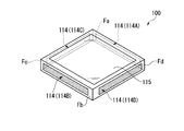
- FIG. 2 is a perspective view illustrating an external configuration of the electronic apparatus 100 according to the present embodiment.
- the housing of the electronic device 100 holds the display unit 115 and the contact detection unit 114.
- the display unit 115 is provided on the plate surface of the housing.
- a surface on which the display unit 115 is provided in the housing is hereinafter referred to as a display surface.
- the contact detection unit 114 is provided on four side surfaces Fa to Fd corresponding to the four sides surrounding the display surface of the housing.
- the contact detection unit 114 provided on the side surface Fa is referred to as a contact detection unit 114A
- the contact detection unit 114 provided on the side surface Fb is referred to as a contact detection unit 114B
- the contact detection unit 114 provided on the side surface Fc is the contact detection unit 114C
- the contact detection unit 114 provided on the side surface Fd is the contact detection unit 114D.
- the symbols A to D are omitted, and are simply referred to as “each contact detection unit 114” or “contact detection unit 114”.
- the contact detection units 114A to 114D detect the presence / absence and contact position of an external contact (for example, by a user) on each of the side surfaces Fa to Fd.
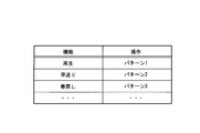
- FIG. 3 is a schematic diagram illustrating a data structure and a data example of an operation table stored in the operation storage unit 11 according to the present embodiment.
- the operation table is data in a two-dimensional tabular format composed of rows and columns, and has columns of items of functions and operations. Each row in this table exists for each function.
- the function is a function that can be executed by the electronic device 100.
- the operation is data indicating an operation for executing a function, and is reference data for movement of the electronic device 100 (main body) detected by the movement detection unit 113 when the user performs an operation.
- an operation for “playing” music or the like is “pattern 1”
- an operation for “fast forward” is “pattern 2”
- an operation for “rewinding” is performed.
- the operation is “pattern 3”.
- FIG. 4 is an image diagram illustrating an example of an operation according to the present embodiment.
- FIG. 4A shows the operation “Pattern 1”.
- the operation “pattern 1” is a gesture for moving the electronic device 100 to draw a circle.
- FIG. 4B is a diagram illustrating the operation “pattern 2”.
- the operation “pattern 2” is a gesture of shaking the electronic device 100 in the vertical direction.
- FIG. 4C shows the operation “pattern 3”.
- the operation “pattern 3” is a gesture of shaking the electronic device 100 in the horizontal direction.
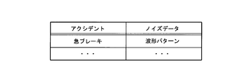
- FIG. 5 is a schematic diagram illustrating a data structure and a data example of the first noise table stored in the noise storage unit 12 according to the present embodiment.
- the first noise table is two-dimensional tabular data composed of rows and columns, and has columns for each item of accident and noise data.
- the accident is an event that is regarded as an accident.
- the noise data is data of motion that becomes noise (data related to a predetermined invalid operation), and is data that indicates the motion of the electronic device 100 detected by the motion detector 113 when an accident occurs.
- the noise data can be acquired in advance by experiments or the like, for example.
- the noise data stores a “waveform pattern” that is detected by the motion detection unit 113 when an accident “sudden braking” occurs.
- the waveform pattern includes data such as the peak value and waveform width of the waveform to be detected.
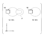
- FIG. 6 is a diagram for explaining the operation of the input determination process according to the present embodiment.
- FIG. 6A shows the movement a of the electronic device 100 in this case.
- the movement indicated by reference numeral a1 is a movement generated by the accident.
- the motion detection unit 113 of the electronic device 100 detects the motion a of the electronic device 100 and outputs data indicating the detected motion a to the control unit 111.
- the noise removing unit 13 of the control unit 111 receives data indicating the movement a ′ obtained by removing the movement of the noise data from the movement a. Generate.
- the noise removing unit 13 generates data indicating the movement a ′ obtained by removing the movement a1 having the same waveform as the noise data “waveform pattern” stored in the noise storage unit 12 from the movement a.
- FIG. 6B shows the movement a ′ of the electronic device 100 after removing the noise data.
- the execution control unit 14 determines a function corresponding to the movement a ′ and controls each unit of the electronic device 100 to execute the function. Specifically, in the example illustrated in FIG. 6, the execution control unit 14 uses the data of the movement a ′ generated by the noise removal unit 13 among the reference data (operations) stored in the operation storage unit 11. It is determined that the operation corresponds to the operation of “Pattern 1” in which the electronic device 100 (main body) is moved so as to draw the circle shown in FIG. Then, the execution control unit 14 determines that the function to be executed is “reproduction” according to the operation table stored in the operation storage unit 11 illustrated in FIG. 3, and controls each unit of the electronic device 100 to execute “ Perform the “Play” function.
- the electronic device 100 performs a movement a ′ obtained by removing the movement a1 generated by the accident from the detected movement a. As input. Thereby, it is possible to prevent an input operation unintended by the user due to the occurrence of an accident.
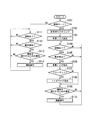
- FIG. 7 is a flowchart showing the procedure of the input determination process according to the present embodiment.
- the control unit 111 determines whether or not the mode of the electronic device 100 is a boarding mode (step S101).
- the control unit 111 monitors a stationary wave of the movement of the electronic device (main body) 100 (step S102). Specifically, the control unit 111 monitors shaking motion detected by the motion detection unit 113 for a predetermined period (for example, several seconds).
- the control unit 111 sets the monitored shaking movement as background noise (step S103). Specifically, the control unit 111 sets the peak value in the monitored fluctuation waveform as the background noise threshold.
- the control unit 111 determines whether or not the contact detection unit 114 has detected contact (step S104). When the contact detection part 114 has not detected contact (step S104: No), it returns to step S104. On the other hand, when the contact detection unit 114 detects contact (step S104: Yes), the control unit 111 determines whether the motion detection unit 113 has detected a motion (step S105). When the motion detection unit 113 has not detected a motion (step S105: No), the process returns to step S104. On the other hand, when the motion detection unit 113 detects a motion (step S105: Yes), the control unit 111 removes background noise from the detected motion (step S106). Specifically, the control unit 111 generates motion data A obtained by subtracting the background noise threshold from the motion magnitude detected by the motion detection unit 113.
- the noise removal unit 13 of the control unit 111 determines whether or not an accident has occurred (step S107). Specifically, the noise removing unit 13 determines whether or not the noise data stored in the noise storage unit 12 is included in the motion data A generated in step S106. When the accident occurs (step S107: Yes), the noise removing unit 13 removes the noise data included in the motion data A from the motion data A (step S108).
- step S109 the execution control unit 14 of the control unit 111 determines whether or not the movement of the electronic device (main body) 100 is an operation for executing a function (step S109). Specifically, the execution control unit 14 determines whether or not reference data (operation) corresponding to movement data of the electronic device 100 is stored in the operation storage unit 11. The corresponding data is data in which the trajectories drawn by the movement are almost the same (within a predetermined range).
- step S109: No the process returns to step S104.
- step S109: Yes the execution control unit 14 executes a function corresponding to this operation (step S110), and returns to step S104.
- step S111 determines whether or not the contact detection unit 114 has detected contact (step S111).
- step S111: No determines whether the contact detection unit 114 has detected contact (step S111: Yes).
- step S112 determines whether the motion detection unit 113 has detected a motion (step S112).
- step S112 when the motion detection unit 113 detects a motion (step S112: Yes), the execution control unit 14 of the control unit 111 determines whether or not the motion of the electronic device 100 is an operation for executing a function. (Step S113). When the movement of the electronic device 100 is not an operation for executing the function (step S113: No), the process returns to step S111. On the other hand, when the movement of the electronic device 100 is an operation for executing a function (step S113: Yes), the execution control unit 14 executes a function corresponding to this operation (step S114) and returns to step S111. .
- the electronic device 100 stores the data of the movement due to the accident as noise data in advance, and detects when the data indicating the detected movement of the electronic device 100 includes the noise data. Noise data is removed from data indicating movement. Then, the electronic device 100 executes a function based on data (filtered data) indicating the movement from which the noise data is removed. As a result, the electronic device 100 can prevent an input due to the movement even when there is a movement unintended by the user due to the accident.
- the noise storage unit 12 of the electronic device 100 stores movement data and movement data that becomes noise among the movements.
- the noise removal unit 13 calculates the noise storage unit 12 based on the detected movement of the electronic device 100.
- the motion data from which the motion that becomes the noise stored in is removed is generated. Since other configurations are the same as those of the first embodiment, description thereof is omitted.
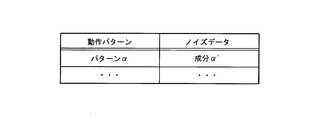
- FIG. 8 is a schematic diagram illustrating a data structure and a data example of the second noise table stored in the noise storage unit 12 according to the present embodiment.
- the second noise table is two-dimensional tabular data composed of rows and columns, and has columns of items of operation patterns and noise data.
- the motion pattern represents an unnatural motion (a motion that is difficult for a human, a motion that is substantially impossible for a human) as a human motion, and indicates the motion of the electronic device 100 detected by the motion detection unit 113 during such motion. It is data.
- the noise data is movement data that becomes noise among the movements included in the operation pattern.
- the operation pattern and noise data are acquired in advance by experiments or the like.
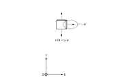
- FIG. 9 is a diagram illustrating an example of an operation pattern according to the present embodiment.
- a human cannot move the electronic device 100 sideways without temporarily stopping while the electronic device 100 is being shaken vertically. For this reason, it is considered that an accident such as a sudden brake occurred when the electronic device 100 moved in the horizontal direction while being vertically shaken.
- the illustrated operation pattern “pattern ⁇ ” indicates an operation in which the electronic device 100 moves in the horizontal direction without temporarily stopping when the electronic device 100 is shaken vertically.
- the noise data “component ⁇ ′” indicates the movement in the horizontal direction among the operations indicated by the “pattern ⁇ ”.
- FIG. 10 is a diagram for explaining the operation of the input determination process according to the present embodiment.
- FIG. 10A shows the movement b of the electronic device 100 in this case.
- the movement indicated by reference sign b1 is a movement generated by the accident.
- the motion detection unit 113 of the electronic device 100 detects the motion b of the electronic device 100 and outputs data indicating the detected motion b to the control unit 111.
- the noise removing unit 13 of the control unit 111 when an operation pattern corresponding to the motion b is stored in the noise storage unit 12, data indicating the motion b ′ obtained by removing the motion of noise data in the motion pattern from the motion b. Is generated.
- the motion pattern corresponding to the motion b is a motion pattern in which the difference between the trajectory in the motion pattern and the trajectory in the motion b is within a predetermined threshold.
- the noise removing unit 13 determines that the motion b corresponds to the motion pattern “pattern ⁇ ”, and generates data indicating the motion b ′ obtained by removing the motion b1 corresponding to the component ⁇ ′ from the motion b.
- FIG. 10B shows the movement b ′ of the electronic device 100 after removing the noise data.
- the execution control unit 14 executes a function corresponding to the movement b ′.
- the electronic device 100 receives the motion b ′ obtained by removing the motion b1 generated by the accident from the detected motion b. Thereby, it is possible to prevent an input operation unintended by the user due to the occurrence of an accident.
- FIG. 11 is a flowchart illustrating the procedure of the input determination process according to the present embodiment. Since the processing from step S201 to S206 is the same as the processing from step S101 to S106 described above, description thereof is omitted. Subsequent to step S206, the noise removal unit 13 of the control unit 111 determines whether or not an operation pattern corresponding to the motion data A generated in step S206 is stored in the noise storage unit 12 (step S207). . When there is a corresponding operation pattern (step S207: Yes), the noise removal unit 13 removes noise data corresponding to this operation pattern from the motion data A (step S208). Since the processing shown in steps S209 to S214 is the same as the processing shown in steps S109 to S114 described above, description thereof is omitted.
- the electronic device 100 stores in advance an operation pattern that is an unnatural motion as a human motion, and detects when the detected motion of the electronic device 100 corresponds to the motion pattern. Noise data is removed from the motion. Then, the electronic device 100 executes a function based on data (filtered data) indicating the movement from which the noise data is removed. As a result, the electronic device 100 can prevent an input due to the movement even when there is a movement unintended by the user due to the accident.
- a program for realizing each step shown in FIG. 7 or FIG. 11 is recorded on a computer-readable recording medium, and the program recorded on the recording medium is read into a computer system and executed, whereby an image is obtained. Display processing may be performed.
- the “computer system” may include an OS and hardware such as peripheral devices.
- “Computer-readable recording medium” means a floppy (registered trademark) disk, a magneto-optical disk, an SD card, a writable non-volatile memory such as a flash memory, a portable medium such as a CD-ROM, and a computer system.
- a built-in storage device such as a hard disk.
- the “computer-readable recording medium” refers to a volatile memory (for example, DRAM (Dynamic DRAM)) in a computer system that becomes a server or a client when a program is transmitted via a network such as the Internet or a communication line such as a telephone line. Random Access Memory)), etc., which hold programs for a certain period of time.
- the program may be transmitted from a computer system storing the program in a storage device or the like to another computer system via a transmission medium or by a transmission wave in the transmission medium.
- the “transmission medium” for transmitting the program refers to a medium having a function of transmitting information, such as a network (communication network) such as the Internet or a communication line (communication line) such as a telephone line.
- the program may be for realizing a part of the functions described above. Furthermore, what can implement
- noise removal processing (steps S107 to S108 and S207 to S208) for removing noise data from the detected motion is performed.
- Noise removal processing may be performed.
- the noise removal process may be performed when the motion detection unit 113 detects a certain fluctuation for a predetermined time or more in the normal mode.
- the noise storage unit 12 of the electronic device 100 may store both the first noise table according to the first embodiment and the second noise table according to the second embodiment.
- the noise removing unit 13 executes both the noise removing process according to the first embodiment (steps S107 to S108) and the noise removing process according to the second embodiment (steps S207 to S208).
- the control unit 111 can determine that the boarding mode should be set.
- the control unit 111 detects that the operator is on a vibrating body such as a vehicle (car, train, bicycle, ship, aircraft, other transportation means, etc.), and executes noise removal processing based on the detection result. be able to.
- the electronic device 100 performs a noise removal mode (riding mode) in which the noise removal process is performed based on the assumption that the operator is on the vibrating body, and normally avoids the noise removal process. It can have a mode (non-ride mode).
- the boarding mode can be switched manually or automatically.
Landscapes
- Engineering & Computer Science (AREA)
- Computer Hardware Design (AREA)
- Theoretical Computer Science (AREA)
- Human Computer Interaction (AREA)
- Physics & Mathematics (AREA)
- General Engineering & Computer Science (AREA)
- General Physics & Mathematics (AREA)
- User Interface Of Digital Computer (AREA)
Abstract
電子機器(100)は、各機能を実行するための本体の動きの基準データを記憶する操作記憶部(11)と、ノイズとなる動きのデータを記憶するノイズ記憶部(12)と、本体の動きを検出する動き検出部(113)と、動き検出部(113)により検出された本体の動きに、ノイズ記憶部(12)に記憶されるノイズとなる動きが含まれる場合に、検出された本体の動きからノイズとなる動きを除去した動きのデータを生成するノイズ除去部(13)と、ノイズ除去部(13)により生成された動きのデータと操作記憶部(11)に記憶されている基準データとに基づいて、実行する機能を判定する実行制御部(14)とを備える。
Description
本発明は、電子機器及び入力方法に関する。
本願は、2012年2月3日に出願された特願2012-22379号に基づき優先権を主張し、その内容をここに援用する。
本願は、2012年2月3日に出願された特願2012-22379号に基づき優先権を主張し、その内容をここに援用する。
3軸加速度センサ等を備える携帯電話や携帯情報端末などの電子機器として、例えば特許文献1が知られている。特許文献1に示すような電子機器においては、3軸加速度センサにより自装置(本体)の動きを検出することで、自装置の動きをインターフェースとして利用するモーションインターフェースを有する。
しかしながら、従来の電子機器においては、例えば、ユーザが車や電車等に乗っているときに急ブレーキ等による急激な揺れが起きた場合、この揺れを自装置(本体)の動きとして検出する。このため、突然の揺れ等のアクシデントが起こると、ユーザにとって所望でない機能が実行される場合がある、という問題がある。
本発明の一態様は、自装置(本体)の動きをインターフェースとして用いる電子機器において、ユーザの意図しない動きによる入力を防ぐことができる電子機器及び入力方法を提供することを目的とする。
本発明の一態様は、各機能を実行するための本体の動きの基準データを記憶する操作記憶部と、ノイズとなる動きのデータを記憶するノイズ記憶部と、本体の動きを検出する動き検出部と、前記動き検出部により検出された本体の動きに、前記ノイズ記憶部に記憶されるノイズとなる動きが含まれる場合に、前記検出された本体の動きから前記ノイズとなる動きを除去した動きのデータを生成するノイズ除去部と、前記ノイズ除去部により生成された動きのデータと前記操作記憶部に記憶されている前記基準データとに基づいて、実行する機能を判定する実行制御部と、を備えることを特徴とする電子機器である。
本発明の態様によれば、自装置(本体)の動きをインターフェースとして用いる電子機器において、ユーザの意図しない動きによる入力を防ぐことができる。
以下、図面を参照しながら本発明の実施形態について詳しく説明する。
[第1の実施形態]
図1は、本発明の第1の実施形態による電子機器(本体)100の機能構成を示すブロック図である。
電子機器100は、携帯電話機、スマートフォン、デジタルカメラ等の携帯情報端末である。電子機器100は、通常モードと乗車モードとを有する。電子機器100は、制御部111と、記憶部112と、動き検出部113と、接触検出部114と、表示部115と、スピーカ116とを含む。
[第1の実施形態]
図1は、本発明の第1の実施形態による電子機器(本体)100の機能構成を示すブロック図である。
電子機器100は、携帯電話機、スマートフォン、デジタルカメラ等の携帯情報端末である。電子機器100は、通常モードと乗車モードとを有する。電子機器100は、制御部111と、記憶部112と、動き検出部113と、接触検出部114と、表示部115と、スピーカ116とを含む。
動き検出部113は、3軸の加速度センサ等を備え、例えばユーザにより自装置が動かされたときの電子機器100の筐体(本体)のXYZ直交座標系における動きを検出する。
ここで、XYZ直交座標系において、重力方向をYとする。また、Y方向に直交する平面をXZ平面とし、XZ平面において直交する方向をそれぞれX方向及びZ方向とする。なお、以下、Y方向を縦方向と呼び、X方向を横方向と呼ぶ。
接触検出部114は、電子機器100の筐体において、表示部115の表示面が設置される面に対する側面に設置され、接触の有無及び接触位置を検出する。
ここで、XYZ直交座標系において、重力方向をYとする。また、Y方向に直交する平面をXZ平面とし、XZ平面において直交する方向をそれぞれX方向及びZ方向とする。なお、以下、Y方向を縦方向と呼び、X方向を横方向と呼ぶ。
接触検出部114は、電子機器100の筐体において、表示部115の表示面が設置される面に対する側面に設置され、接触の有無及び接触位置を検出する。
表示部115は、例えば液晶表示パネルや、有機ELパネルなどであり、画像等を表示する。表示部115の表示面上には、不図示のタッチパネルが設けられる。接触検出部114及びタッチパネルが、電子機器100のモードを「通常モード」又は「乗車モード」に切り替える操作部である。
スピーカ116は、一般的なスピーカであり、音声を出力する。
スピーカ116は、一般的なスピーカであり、音声を出力する。
記憶部112は、各機能を実行するための電子機器(本体)100の動きの基準データを記憶する操作記憶部11と、ノイズとなる動き(所定の無効動作)のデータを記憶するノイズ記憶部12と、を有する。
操作記憶部11は、複数の機能に対応する電子機器100の複数の動きをそれぞれ基準データとして記憶する。ノイズ記憶部12は、複数の無効な動きに関するデータを記憶する。
制御部111は、電子機器100の各部を統括して制御する。制御部111は、ノイズ除去部13と、実行制御部14とを含む。
ノイズ除去部13は、動き検出部113により検出された電子機器100の動きに、ノイズ記憶部12に記憶されるノイズとなる動き(無効な動き)が含まれる場合に、検出された電子機器100の動きからノイズとなる動き(無効な動き)を除去した動きのデータ(フィルタされたデータ)を生成する。
実行制御部14は、ノイズ除去部13により生成された動きのデータ(フィルタされたデータ)と操作記憶部11に記憶されている基準データとに基づいて、実行すべき機能を判定する。
また、制御部111は、操作部からの入力に基づいて、電子機器100のモードを「通常モード」又は「乗車モード」に切り替える。乗車モードは、ノイズ除去部13が検出された自装置(本体)の動きからノイズとなる動き(無効な動き)を除去するモードである。
図2は、本実施形態による電子機器100の外観構成を示す斜視図である。
電子機器100の筐体は、表示部115と接触検出部114とを保持する。
表示部115は、筐体のうち板面に設けられている。筐体のうち表示部115が設けられる面を、以下表示面と表記する。
接触検出部114は、筐体のうち表示面を囲む4辺に相当する4つの側面Fa~Fdに設けられている。以下、説明の便宜を図るため、側面Faに設けられる接触検出部114を接触検出部114Aとし、側面Fbに設けられる接触検出部114を接触検出部114Bとし、側面Fcに設けられる接触検出部114を接触検出部114Cとし、側面Fdに設けられる接触検出部114を接触検出部114Dとする。
なお、各接触検出部114A~114Dに共通する事項については、A~Dの符号を省略し、単に「各接触検出部114」又は「接触検出部114」と記す。接触検出部114A~114Dは、各側面Fa~Fdにおいて外部からの(例えばユーザの)接触の有無及び接触位置を検出する。
図3は、本実施形態による操作記憶部11が記憶する操作テーブルのデータ構造及びデータ例を示す概略図である。図示するように、操作テーブルは、行と列からなる2次元の表形式のデータであり、機能と、操作との各項目の列を有している。このテーブルの各行は機能毎に存在する。
機能は、電子機器100が実行可能な機能である。操作は、機能を実行するための操作を示すデータであり、ユーザが操作をしたときに、動き検出部113が検出する電子機器100(本体)の動きの基準データである。
本図に示す例では、音楽等の「再生」をするための操作は「パターン1」であり、「早送り」をするための操作は「パターン2」であり、「巻戻し」をするための操作は「パターン3」である。
機能は、電子機器100が実行可能な機能である。操作は、機能を実行するための操作を示すデータであり、ユーザが操作をしたときに、動き検出部113が検出する電子機器100(本体)の動きの基準データである。
本図に示す例では、音楽等の「再生」をするための操作は「パターン1」であり、「早送り」をするための操作は「パターン2」であり、「巻戻し」をするための操作は「パターン3」である。
図4は、本実施形態による操作の一例を示すイメージ図である。
図4(a)は、操作「パターン1」を示す図である。操作「パターン1」は、円を描くように電子機器100を動かすジェスチャーである。また、図4(b)は、操作「パターン2」を示す図である。操作「パターン2」は、電子機器100を縦方向に振るジェスチャーである。また、図4(c)は、操作「パターン3」を示す図である。操作「パターン3」は、電子機器100を横方向に振るジェスチャーである。
図4(a)は、操作「パターン1」を示す図である。操作「パターン1」は、円を描くように電子機器100を動かすジェスチャーである。また、図4(b)は、操作「パターン2」を示す図である。操作「パターン2」は、電子機器100を縦方向に振るジェスチャーである。また、図4(c)は、操作「パターン3」を示す図である。操作「パターン3」は、電子機器100を横方向に振るジェスチャーである。
図5は、本実施形態によるノイズ記憶部12が記憶する第1のノイズテーブルのデータ構造及びデータ例を示す概略図である。図示するように、第1のノイズテーブルは、行と列からなる2次元の表形式のデータであり、アクシデントと、ノイズデータとの各項目の列を有している。
図5において、アクシデントは、アクシデントとみなす事象である。ノイズデータは、ノイズとなる動きのデータ(所定の無効動作に関するデータ)であり、アクシデントが発生したときに動き検出部113が検出する電子機器100の動きを示すデータである。ノイズデータは、例えば予め実験等により取得することができる。
本図に示す例では、ノイズデータには、アクシデント「急ブレーキ」が発生したときに、動き検出部113が検出する「波形パターン」が格納されている。波形パターンは、検出する波形のピーク値や波形幅等のデータを含む。
図5において、アクシデントは、アクシデントとみなす事象である。ノイズデータは、ノイズとなる動きのデータ(所定の無効動作に関するデータ)であり、アクシデントが発生したときに動き検出部113が検出する電子機器100の動きを示すデータである。ノイズデータは、例えば予め実験等により取得することができる。
本図に示す例では、ノイズデータには、アクシデント「急ブレーキ」が発生したときに、動き検出部113が検出する「波形パターン」が格納されている。波形パターンは、検出する波形のピーク値や波形幅等のデータを含む。
次に、図6及び図7を参照して、本実施形態による電子機器100における入力判定処理について説明する。図6は、本実施形態による入力判定処理の動作を説明するための図である。
以下、乗車中のユーザが円を描くジェスチャーによる入力操作をしている際に、急ブレーキ等のアクシデントが起こった場合を例に説明する。図6(a)は、この場合における電子機器100の動きaを示す。符号a1で示す動きは、アクシデントにより発生した動きである。
以下、乗車中のユーザが円を描くジェスチャーによる入力操作をしている際に、急ブレーキ等のアクシデントが起こった場合を例に説明する。図6(a)は、この場合における電子機器100の動きaを示す。符号a1で示す動きは、アクシデントにより発生した動きである。
電子機器100の動き検出部113は、電子機器100の動きaを検出し、検出した動きaを示すデータを制御部111に出力する。制御部111のノイズ除去部13は、ノイズ記憶部12に記憶されるノイズデータが動きaを示すデータに含まれる場合に、動きaからこのノイズデータの動きを除去した動きa´を示すデータを生成する。
本図に示す例では、ノイズ除去部13は、ノイズ記憶部12に記憶されるノイズデータ「波形パターン」とほぼ同じ波形である動きa1を動きaから除去した動きa´を示すデータを生成する。
図6(b)は、ノイズデータ除去後の電子機器100の動きa´を示す。実行制御部14は、動きa´に対応する機能を判定し、電子機器100の各部を制御して機能を実行する。
具体的に、図6に示す例では、実行制御部14は、ノイズ除去部13により生成された動きa´のデータが、操作記憶部11に記憶されている基準データ(操作)のうち、図4(a)に示した円を描くように電子機器100(本体)を動かす「パターン1」の操作に対応する、と判定する。
そして、実行制御部14は、図3に示した操作記憶部11に記憶されている操作テーブルに従って、実行する機能が「再生」である、と判定し、電子機器100の各部を制御して「再生」の機能を実行する。
このように、アクシデントによりユーザの意図しない動き(無効な動き)a1が発生した場合であっても、電子機器100は、検出された動きaからアクシデントにより発生した動きa1を除去した動きa´を入力とする。これにより、アクシデントの発生によりユーザの意図しない入力操作がされることを防ぐことができる。
図7は、本実施形態による入力判定処理の手順を示すフローチャートである。
まず、制御部111は、電子機器100のモードが乗車モードであるか否かを判定する(ステップS101)。
電子機器100のモードが乗車モードである場合(ステップS101:Yes)、制御部111は、電子機器(本体)100の動きの定常波をモニタリングする(ステップS102)。
具体的には、制御部111は、所定の期間(例えば、数秒)、動き検出部113が検出する揺れの動きをモニタリングする。
次に、制御部111は、モニタリングした揺れの動きを背景ノイズとする(ステップS103)。具体的には、制御部111は、モニタリングした揺れの波形におけるピーク値を背景ノイズ閾値とする。
まず、制御部111は、電子機器100のモードが乗車モードであるか否かを判定する(ステップS101)。
電子機器100のモードが乗車モードである場合(ステップS101:Yes)、制御部111は、電子機器(本体)100の動きの定常波をモニタリングする(ステップS102)。
具体的には、制御部111は、所定の期間(例えば、数秒)、動き検出部113が検出する揺れの動きをモニタリングする。
次に、制御部111は、モニタリングした揺れの動きを背景ノイズとする(ステップS103)。具体的には、制御部111は、モニタリングした揺れの波形におけるピーク値を背景ノイズ閾値とする。
次に、制御部111は、接触検出部114が接触を検出しているか否かを判定する(ステップS104)。接触検出部114が接触を検出していない場合(ステップS104:No)、ステップS104へ戻る。
一方、接触検出部114が接触を検出している場合(ステップS104:Yes)、制御部111は、動き検出部113が動きを検出したか否かを判定する(ステップS105)。動き検出部113が動きを検出していない場合(ステップS105:No)、ステップS104へ戻る。
一方、動き検出部113が動きを検出した場合(ステップS105:Yes)、制御部111は、検出した動きから背景ノイズを除去する(ステップS106)。具体的には、制御部111は、動き検出部113が検出した動きの大きさから背景ノイズ閾値を減算した動きのデータAを生成する。
一方、接触検出部114が接触を検出している場合(ステップS104:Yes)、制御部111は、動き検出部113が動きを検出したか否かを判定する(ステップS105)。動き検出部113が動きを検出していない場合(ステップS105:No)、ステップS104へ戻る。
一方、動き検出部113が動きを検出した場合(ステップS105:Yes)、制御部111は、検出した動きから背景ノイズを除去する(ステップS106)。具体的には、制御部111は、動き検出部113が検出した動きの大きさから背景ノイズ閾値を減算した動きのデータAを生成する。
次に、制御部111のノイズ除去部13が、アクシデントが発生したか否かを判定する(ステップS107)。具体的には、ノイズ除去部13は、ノイズ記憶部12に記憶されているノイズデータが、ステップS106において生成された動きのデータAに含まれるか否かを判定する。
アクシデントが発生した場合(ステップS107:Yes)、ノイズ除去部13は、動きのデータAに含まれるノイズデータを動きのデータAから除去する(ステップS108)。
アクシデントが発生した場合(ステップS107:Yes)、ノイズ除去部13は、動きのデータAに含まれるノイズデータを動きのデータAから除去する(ステップS108)。
ステップS107又はS108に続いて、制御部111の実行制御部14が、電子機器(本体)100の動きが機能を実行するための操作であるか否かを判定する(ステップS109)。
具体的には、実行制御部14は、電子機器100の動きのデータに対応する基準データ(操作)が操作記憶部11に記憶されているか否かを判定する。対応するデータとは、動きが描く軌道がほぼ同一(所定の範囲内)であるデータである。電子機器100の動きが機能を実行するための操作でない場合(ステップS109:No)、ステップS104へ戻る。
一方、電子機器100の動きが機能を実行するための操作である場合(ステップS109:Yes)、実行制御部14は、この操作に対応する機能を実行して(ステップS110)、ステップS104へ戻る。
具体的には、実行制御部14は、電子機器100の動きのデータに対応する基準データ(操作)が操作記憶部11に記憶されているか否かを判定する。対応するデータとは、動きが描く軌道がほぼ同一(所定の範囲内)であるデータである。電子機器100の動きが機能を実行するための操作でない場合(ステップS109:No)、ステップS104へ戻る。
一方、電子機器100の動きが機能を実行するための操作である場合(ステップS109:Yes)、実行制御部14は、この操作に対応する機能を実行して(ステップS110)、ステップS104へ戻る。
一方、電子機器100のモードが乗車モードでない場合(ステップS101:No)、制御部111は、接触検出部114が接触を検出しているか否かを判定する(ステップS111)。接触検出部114が接触を検出していない場合(ステップS111:No)、ステップS111へ戻る。
一方、接触検出部114が接触を検出している場合(ステップS111:Yes)、制御部111は、動き検出部113が動きを検出したか否かを判定する(ステップS112)。動き検出部113が動きを検出していない場合(ステップS112:No)、ステップS111へ戻る。
一方、接触検出部114が接触を検出している場合(ステップS111:Yes)、制御部111は、動き検出部113が動きを検出したか否かを判定する(ステップS112)。動き検出部113が動きを検出していない場合(ステップS112:No)、ステップS111へ戻る。
一方、動き検出部113が動きを検出した場合(ステップS112:Yes)、制御部111の実行制御部14が、電子機器100の動きが機能を実行するための操作であるか否かを判定する(ステップS113)。電子機器100の動きが機能を実行するための操作でない場合(ステップS113:No)、ステップS111へ戻る。
一方、電子機器100の動きが機能を実行するための操作である場合(ステップS113:Yes)、実行制御部14は、この操作に対応する機能を実行して(ステップS114)、ステップS111へ戻る。
一方、電子機器100の動きが機能を実行するための操作である場合(ステップS113:Yes)、実行制御部14は、この操作に対応する機能を実行して(ステップS114)、ステップS111へ戻る。
このように、本実施形態によれば、電子機器100は、アクシデントによる動きのデータをノイズデータとして予め記憶し、検出した電子機器100の動きを示すデータにノイズデータが含まれる場合に、検出した動きを示すデータからノイズデータを除去する。そして、電子機器100は、ノイズデータを除去した動きを示すデータ(フィルタされたデータ)に基づいて機能を実行する。
これにより、電子機器100は、アクシデントによりユーザの意図しない動きがあった場合でも、その動きによる入力を防ぐことができる。
これにより、電子機器100は、アクシデントによりユーザの意図しない動きがあった場合でも、その動きによる入力を防ぐことができる。
[第2の実施形態]
次に、本発明の第2の実施形態について説明する。
本実施形態による電子機器100のノイズ記憶部12は、動きのデータと、この動きのうちノイズとなる動きのデータを記憶する。
ノイズ除去部13は、動き検出部113により検出された電子機器100の動きに対応する動きがノイズ記憶部12に記憶されている場合に、検出された電子機器100の動きから、ノイズ記憶部12に記憶されているノイズとなる動きを除去した動きのデータを生成する。
他の構成は第1の実施形態と同様であるため、説明を省略する。
次に、本発明の第2の実施形態について説明する。
本実施形態による電子機器100のノイズ記憶部12は、動きのデータと、この動きのうちノイズとなる動きのデータを記憶する。
ノイズ除去部13は、動き検出部113により検出された電子機器100の動きに対応する動きがノイズ記憶部12に記憶されている場合に、検出された電子機器100の動きから、ノイズ記憶部12に記憶されているノイズとなる動きを除去した動きのデータを生成する。
他の構成は第1の実施形態と同様であるため、説明を省略する。
図8は、本実施形態によるノイズ記憶部12が記憶する第2のノイズテーブルのデータ構造及びデータ例を示す概略図である。図示するように、第2のノイズテーブルは、行と列からなる2次元の表形式のデータであり、動作パターンと、ノイズデータとの各項目の列を有している。
動作パターンは、人間の動きとして不自然な動作(人間にとって難しい動作、人間が実質的に不可能な動作)を表し、そのような動作時に動き検出部113が検出する電子機器100の動きを示すデータである。ノイズデータは、動作パターンに含まれる動きのうちノイズとなる動きのデータである。動作パターン及びノイズデータは、予め実験等により取得する。
動作パターンは、人間の動きとして不自然な動作(人間にとって難しい動作、人間が実質的に不可能な動作)を表し、そのような動作時に動き検出部113が検出する電子機器100の動きを示すデータである。ノイズデータは、動作パターンに含まれる動きのうちノイズとなる動きのデータである。動作パターン及びノイズデータは、予め実験等により取得する。
図9は、本実施形態による動作パターンの一例を示す図である。
例えば、人間は、電子機器100を縦に振っている最中に、一旦停止することなく電子機器100を横に動かすことはできない。このため、電子機器100が縦に振られている最中に横方向へ動いた場合、急ブレーキ等のアクシデントが起こったと考えられる。動作パターンには、このような人間の動きとして不自然な動作を示すデータが格納される。
図示する動作パターン「パターンα」は、電子機器100が縦に振られているときに一旦停止することなく横方向へ動く動作を示す。また、ノイズデータ「成分α´」は、「パターンα」が示す動作のうち、横方向への動きを示す。
例えば、人間は、電子機器100を縦に振っている最中に、一旦停止することなく電子機器100を横に動かすことはできない。このため、電子機器100が縦に振られている最中に横方向へ動いた場合、急ブレーキ等のアクシデントが起こったと考えられる。動作パターンには、このような人間の動きとして不自然な動作を示すデータが格納される。
図示する動作パターン「パターンα」は、電子機器100が縦に振られているときに一旦停止することなく横方向へ動く動作を示す。また、ノイズデータ「成分α´」は、「パターンα」が示す動作のうち、横方向への動きを示す。
次に、図10及び図11を参照して、本実施形態による電子機器100における入力判定処理について説明する。図10は、本実施形態による入力判定処理の動作を説明するための図である。
以下、乗車中のユーザが電子機器100を縦に振るジェスチャーによる入力操作をしている際に、急ブレーキ等のアクシデントが起こった場合を例に説明する。図10(a)は、この場合における電子機器100の動きbを示す。符号b1で示す動きは、アクシデントにより発生した動きである。
以下、乗車中のユーザが電子機器100を縦に振るジェスチャーによる入力操作をしている際に、急ブレーキ等のアクシデントが起こった場合を例に説明する。図10(a)は、この場合における電子機器100の動きbを示す。符号b1で示す動きは、アクシデントにより発生した動きである。
電子機器100の動き検出部113は、電子機器100の動きbを検出し、検出した動きbを示すデータを制御部111に出力する。制御部111のノイズ除去部13は、動きbに対応する動作パターンがノイズ記憶部12に記憶されている場合に、この動作パターンにおけるノイズデータの動きを動きbから除去した動きb´を示すデータを生成する。
動きbに対応する動作パターンとは、動作パターンにおける軌道と動きbにおける軌道との差が所定の閾値内である動作パターンである。本図に示す例では、ノイズ除去部13は、動きbが動作パターン「パターンα」に対応すると判定し、成分α´に対応する動きb1を動きbから除去した動きb´を示すデータを生成する。
図10(b)は、ノイズデータ除去後の電子機器100の動きb´を示す。実行制御部14は、動きb´に対応する機能を実行する。
このように、アクシデントによりユーザの意図しない動きb1が発生した場合であっても、電子機器100は、検出された動きbからアクシデントにより発生した動きb1を除去した動きb´を入力とする。これにより、アクシデントの発生によりユーザの意図しない入力操作がされることを防ぐことができる。
図11は、本実施形態による入力判定処理の手順を示すフローチャートである。
ステップS201からS206までの処理は、上述したステップS101からS106までの処理と同様なため、説明を省略する。
ステップS206に続いて、制御部111のノイズ除去部13は、ステップS206において生成された動きのデータAに対応する動作パターンがノイズ記憶部12に記憶されているか否かを判定する(ステップS207)。
対応する動作パターンがある場合(ステップS207:Yes)、ノイズ除去部13は、この動作パターンに対応するノイズデータを動きデータAから除去する(ステップS208)。
ステップS209からS214に示す処理は、上述したステップS109からS114に示す処理と同様なため、説明を省略する。
このように、本実施形態によれば、電子機器100は、人間の動きとして不自然な動作である動作パターンを予め記憶し、検出した電子機器100の動きが動作パターンに対応する場合に、検出した動きからノイズデータを除去する。そして、電子機器100は、ノイズデータを除去した動きを示すデータ(フィルタされたデータ)に基づいて機能を実行する。
これにより、電子機器100は、アクシデントによりユーザの意図しない動きがあった場合でも、その動きによる入力を防ぐことができる。
これにより、電子機器100は、アクシデントによりユーザの意図しない動きがあった場合でも、その動きによる入力を防ぐことができる。
また、図7又は図11に示す各ステップを実現するためのプログラムをコンピュータ読み取り可能な記録媒体に記録して、この記録媒体に記録されたプログラムをコンピュータシステムに読み込ませ、実行することにより、画像表示処理を行ってもよい。なお、ここでいう「コンピュータシステム」とは、OSや周辺機器等のハードウェアを含むものであってもよい。
また、「コンピュータ読み取り可能な記録媒体」とは、フロッピー(登録商標)ディスク、光磁気ディスク、SDカード、フラッシュメモリ等の書き込み可能な不揮発性メモリ、CD-ROM等の可搬媒体、コンピュータシステムに内蔵されるハードディスク等の記憶装置のことをいう。
また、「コンピュータ読み取り可能な記録媒体」とは、フロッピー(登録商標)ディスク、光磁気ディスク、SDカード、フラッシュメモリ等の書き込み可能な不揮発性メモリ、CD-ROM等の可搬媒体、コンピュータシステムに内蔵されるハードディスク等の記憶装置のことをいう。
さらに「コンピュータ読み取り可能な記録媒体」とは、インターネット等のネットワークや電話回線等の通信回線を介してプログラムが送信された場合のサーバやクライアントとなるコンピュータシステム内部の揮発性メモリ(例えばDRAM(Dynamic Random Access Memory))のように、一定時間プログラムを保持しているものも含むものとする。
また、上記プログラムは、このプログラムを記憶装置等に格納したコンピュータシステムから、伝送媒体を介して、あるいは、伝送媒体中の伝送波により他のコンピュータシステムに伝送されてもよい。ここで、プログラムを伝送する「伝送媒体」は、インターネット等のネットワーク(通信網)や電話回線等の通信回線(通信線)のように情報を伝送する機能を有する媒体のことをいう。
また、上記プログラムは、前述した機能の一部を実現するためのものであっても良い。
さらに、前述した機能をコンピュータシステムにすでに記録されているプログラムとの組み合わせで実現できるもの、いわゆる差分ファイル(差分プログラム)であっても良い。
また、上記プログラムは、このプログラムを記憶装置等に格納したコンピュータシステムから、伝送媒体を介して、あるいは、伝送媒体中の伝送波により他のコンピュータシステムに伝送されてもよい。ここで、プログラムを伝送する「伝送媒体」は、インターネット等のネットワーク(通信網)や電話回線等の通信回線(通信線)のように情報を伝送する機能を有する媒体のことをいう。
また、上記プログラムは、前述した機能の一部を実現するためのものであっても良い。
さらに、前述した機能をコンピュータシステムにすでに記録されているプログラムとの組み合わせで実現できるもの、いわゆる差分ファイル(差分プログラム)であっても良い。
以上、図面を参照してこの発明の実施形態について詳しく説明してきたが、具体的な構成は上述のものに限られることはなく、この発明の要旨を逸脱しない範囲内において様々な設計変更等をすることが可能である。
例えば、上記実施形態においては、電子機器100が乗車モードのときに、検出した動きからノイズデータを除去するノイズ除去処理(ステップS107~S108,S207~S208)をしているが、通常モード時にもノイズ除去処理をしてもよい。或いは、通常モード時に、動き検出部113が一定の揺れを所定時間以上検出した場合にノイズ除去処理をしてもよい。
また、電子機器100のノイズ記憶部12は、第1の実施形態による第1のノイズテーブル及び第2の実施形態による第2のノイズテーブル両方を記憶してもよい。この場合、ノイズ除去部13は、第1の実施形態によるノイズ除去処理(ステップS107~S108)及び第2の実施形態によるノイズ除去処理(ステップS207~S208)両方を実行する。
例えば、動き検出部113の検出結果に基づいて、制御部111は、乗車モードにすべきと判断することができる。制御部111は、操作者が乗物(自動車、電車、自転車、船、航空機、他の輸送手段等)等の振動体上にいることを検出し、その検出結果に基づいてノイズ除去処理を実行することができる。
上述したように、一実施形態において、電子機器100は、操作者が振動体上にいるとの想定に基づきノイズ除去処理を実行するノイズ除去モード(乗車モード)と、ノイズ除去処理を回避する通常モード(非乗車モード)を有することができる。乗車モードは、手動又は自動で切り替えることができる。
100…電子機器 11…操作記憶部 12…ノイズ記憶部 13…ノイズ除去部 14…実行制御部 111…制御部 112…記憶部 113…動き検出部 114…接触検出部 115…表示部 116…スピーカ。
Claims (6)
- 各機能を実行するための本体の動きの基準データを記憶する操作記憶部と、
ノイズとなる動きのデータを記憶するノイズ記憶部と、
本体の動きを検出する動き検出部と、
前記動き検出部により検出された本体の動きに、前記ノイズ記憶部に記憶されるノイズとなる動きが含まれる場合に、前記検出された本体の動きから前記ノイズとなる動きを除去した動きのデータを生成するノイズ除去部と、
前記ノイズ除去部により生成された動きのデータと前記操作記憶部に記憶されている前記基準データとに基づいて、実行する機能を判定する実行制御部と、
を備えることを特徴とする電子機器。 - 前記ノイズ記憶部は、動きのデータと、前記動きのうちノイズとなる動きのデータを記憶し、
前記ノイズ除去部は、前記動き検出部により検出された本体の動きに対応するデータが前記ノイズ記憶部に記憶されている場合に、前記検出された本体の動きから、前記ノイズ記憶部に記憶されている前記動きのうちノイズとなる動きを除去した動きのデータを生成する
ことを特徴とする請求項1に記載の電子機器。 - 前記電子機器の側面に設置され、接触の有無及び接触位置を検出する接触検出部をさらに備え、
前記実行制御部は、前記接触検出部により接触が検出されている場合に、実行する機能を判定する
ことを特徴とする請求項1又は2に記載の電子機器。 - 前記ノイズ除去部が前記検出された本体の動きから前記ノイズとなる動きを除去するモードを有することを特徴とする請求項1から3のうちいずれか1項に記載の電子機器。
- 前記動き検出部が検出した動きから所定の背景ノイズ成分を除去した動きを、前記動き検出部が検出した動きとすることを特徴とする請求項1から4のうちいずれか1項に記載の電子機器。
- 各機能を実行するための本体の動きの基準データを記憶する操作記憶部と、
ノイズとなる動きのデータを記憶するノイズ記憶部と、
本体の動きを検出する動き検出部と、
を備える電子機器で、
前記検出した本体の動きに、前記ノイズ記憶部に記憶されるノイズとなる動きが含まれる場合に、前記検出された本体の動きから前記ノイズとなる動きを除去した動きのデータを生成することと、
前記電子機器が、前記生成した動きのデータと前記操作記憶部に記憶されている前記基準データとに基づいて、実行する機能を判定することと、
を有する入力方法。
Applications Claiming Priority (2)
| Application Number | Priority Date | Filing Date | Title |
|---|---|---|---|
| JP2012022379 | 2012-02-03 | ||
| JP2012-022379 | 2012-09-14 |
Publications (1)
| Publication Number | Publication Date |
|---|---|
| WO2013115357A1 true WO2013115357A1 (ja) | 2013-08-08 |
Family
ID=48905385
Family Applications (1)
| Application Number | Title | Priority Date | Filing Date |
|---|---|---|---|
| PCT/JP2013/052344 Ceased WO2013115357A1 (ja) | 2012-02-03 | 2013-02-01 | 電子機器及び入力方法 |
Country Status (1)
| Country | Link |
|---|---|
| WO (1) | WO2013115357A1 (ja) |
Citations (2)
| Publication number | Priority date | Publication date | Assignee | Title |
|---|---|---|---|---|
| JP2008293423A (ja) * | 2007-05-28 | 2008-12-04 | Panasonic Corp | モーション識別装置 |
| JP2010009498A (ja) * | 2008-06-30 | 2010-01-14 | Asahi Kasei Electronics Co Ltd | モーションセンサ |
-
2013
- 2013-02-01 WO PCT/JP2013/052344 patent/WO2013115357A1/ja not_active Ceased
Patent Citations (2)
| Publication number | Priority date | Publication date | Assignee | Title |
|---|---|---|---|---|
| JP2008293423A (ja) * | 2007-05-28 | 2008-12-04 | Panasonic Corp | モーション識別装置 |
| JP2010009498A (ja) * | 2008-06-30 | 2010-01-14 | Asahi Kasei Electronics Co Ltd | モーションセンサ |
Similar Documents
| Publication | Publication Date | Title |
|---|---|---|
| JP6006065B2 (ja) | 携帯端末で自動画面回転を防止するための装置及び方法 | |
| JP6046729B2 (ja) | 全方向ジェスチャー入力 | |
| JP5639489B2 (ja) | 情報処理装置及びその制御方法、プログラム、並びに記憶媒体 | |
| KR102362465B1 (ko) | 프로그램, 전자 장치, 및 방법 | |
| US20130197916A1 (en) | Terminal device, speech recognition processing method of terminal device, and related program | |
| JP6333663B2 (ja) | 情報処理装置、情報処理装置の制御方法、およびプログラム | |
| JP2015125780A (ja) | ジェスチャベース入力のために触覚フィードバックを提供するためのシステム及び方法 | |
| JP2013137540A (ja) | 機械的ノイズ低減システム | |
| US20140111419A1 (en) | Information processing apparatus, information processing method, and computer program product | |
| JPWO2013121807A1 (ja) | 情報処理装置、情報処理方法およびコンピュータプログラム | |
| JP6103835B2 (ja) | 情報処理装置およびその制御方法 | |
| JP6081324B2 (ja) | 操作入力装置、携帯型情報端末、操作入力装置の制御方法、プログラム、及び記録媒体 | |
| JPWO2014155747A1 (ja) | 端末装置、端末装置の制御方法、プログラム、及び情報記憶媒体 | |
| JP5861707B2 (ja) | 電子機器及び入力方法 | |
| JP2014067289A (ja) | 情報処理装置および表示制御方法 | |
| JPWO2013042530A1 (ja) | 表示装置、表示制御方法およびプログラム | |
| JP2015125777A (ja) | ジェスチャベース入力からタッチ表面への遷移の指示 | |
| JP6174048B2 (ja) | モバイル装置のショックタッチ保護 | |
| WO2018047543A1 (ja) | 出力制御装置、出力制御方法、およびプログラム | |
| WO2023048719A1 (en) | Private display for head mountable device authentication | |
| JP2017162418A (ja) | 表示装置 | |
| JP6352918B2 (ja) | 電子機器、および電子機器の制御プログラム | |
| JP6195799B2 (ja) | 情報端末装置および制御プログラム | |
| CN118337912A (zh) | 控制方法、装置、电子设备和可读存储介质 | |
| CN114500733A (zh) | 电容声控制方法、装置、设备及介质 |
Legal Events
| Date | Code | Title | Description |
|---|---|---|---|
| 121 | Ep: the epo has been informed by wipo that ep was designated in this application |
Ref document number: 13744166 Country of ref document: EP Kind code of ref document: A1 |
|
| NENP | Non-entry into the national phase |
Ref country code: DE |
|
| 122 | Ep: pct application non-entry in european phase |
Ref document number: 13744166 Country of ref document: EP Kind code of ref document: A1 |
|
| NENP | Non-entry into the national phase |
Ref country code: JP |