WO2013111888A1 - 通信制御方法、基地局、及びユーザ端末 - Google Patents
通信制御方法、基地局、及びユーザ端末 Download PDFInfo
- Publication number
- WO2013111888A1 WO2013111888A1 PCT/JP2013/051668 JP2013051668W WO2013111888A1 WO 2013111888 A1 WO2013111888 A1 WO 2013111888A1 JP 2013051668 W JP2013051668 W JP 2013051668W WO 2013111888 A1 WO2013111888 A1 WO 2013111888A1
- Authority
- WO
- WIPO (PCT)
- Prior art keywords
- cell
- user terminal
- general
- general cell
- connection
- Prior art date
Links
- 238000000034 method Methods 0.000 title claims description 42
- 238000004891 communication Methods 0.000 title claims description 30
- 230000005540 biological transmission Effects 0.000 claims abstract description 23
- 238000010295 mobile communication Methods 0.000 claims abstract description 12
- 230000000694 effects Effects 0.000 claims abstract description 7
- 238000005259 measurement Methods 0.000 claims description 40
- 210000004027 cell Anatomy 0.000 description 254
- 238000010586 diagram Methods 0.000 description 8
- 238000013507 mapping Methods 0.000 description 5
- 238000012545 processing Methods 0.000 description 5
- 238000007726 management method Methods 0.000 description 4
- 210000004754 hybrid cell Anatomy 0.000 description 3
- 230000015556 catabolic process Effects 0.000 description 2
- 238000006731 degradation reaction Methods 0.000 description 2
- 101150039363 SIB2 gene Proteins 0.000 description 1
- 230000015572 biosynthetic process Effects 0.000 description 1
- 230000006835 compression Effects 0.000 description 1
- 238000007906 compression Methods 0.000 description 1
- 238000007796 conventional method Methods 0.000 description 1
- 238000012937 correction Methods 0.000 description 1
- 125000004122 cyclic group Chemical group 0.000 description 1
- 230000006837 decompression Effects 0.000 description 1
- 230000006866 deterioration Effects 0.000 description 1
- 238000002360 preparation method Methods 0.000 description 1
- 238000003786 synthesis reaction Methods 0.000 description 1
- 238000012546 transfer Methods 0.000 description 1
Images


Classifications
-
- H—ELECTRICITY
- H04—ELECTRIC COMMUNICATION TECHNIQUE
- H04W—WIRELESS COMMUNICATION NETWORKS
- H04W76/00—Connection management
- H04W76/40—Connection management for selective distribution or broadcast
-
- H—ELECTRICITY
- H04—ELECTRIC COMMUNICATION TECHNIQUE
- H04W—WIRELESS COMMUNICATION NETWORKS
- H04W36/00—Hand-off or reselection arrangements
- H04W36/0005—Control or signalling for completing the hand-off
- H04W36/0007—Control or signalling for completing the hand-off for multicast or broadcast services, e.g. MBMS
-
- H—ELECTRICITY
- H04—ELECTRIC COMMUNICATION TECHNIQUE
- H04W—WIRELESS COMMUNICATION NETWORKS
- H04W36/00—Hand-off or reselection arrangements
- H04W36/0005—Control or signalling for completing the hand-off
- H04W36/0083—Determination of parameters used for hand-off, e.g. generation or modification of neighbour cell lists
- H04W36/00837—Determination of triggering parameters for hand-off
-
- H—ELECTRICITY
- H04—ELECTRIC COMMUNICATION TECHNIQUE
- H04W—WIRELESS COMMUNICATION NETWORKS
- H04W36/00—Hand-off or reselection arrangements
- H04W36/04—Reselecting a cell layer in multi-layered cells
-
- H—ELECTRICITY
- H04—ELECTRIC COMMUNICATION TECHNIQUE
- H04W—WIRELESS COMMUNICATION NETWORKS
- H04W16/00—Network planning, e.g. coverage or traffic planning tools; Network deployment, e.g. resource partitioning or cells structures
- H04W16/24—Cell structures
- H04W16/32—Hierarchical cell structures
-
- H—ELECTRICITY
- H04—ELECTRIC COMMUNICATION TECHNIQUE
- H04W—WIRELESS COMMUNICATION NETWORKS
- H04W84/00—Network topologies
- H04W84/02—Hierarchically pre-organised networks, e.g. paging networks, cellular networks, WLAN [Wireless Local Area Network] or WLL [Wireless Local Loop]
- H04W84/04—Large scale networks; Deep hierarchical networks
- H04W84/042—Public Land Mobile systems, e.g. cellular systems
- H04W84/045—Public Land Mobile systems, e.g. cellular systems using private Base Stations, e.g. femto Base Stations, home Node B
Definitions
- the present invention relates to a communication control method, a base station, and a user terminal in a mobile communication system including a general cell that supports PTM distribution of MBMS data and a specific cell that does not support PTM distribution of MBMS data.
- eMBMS evolved MBMS
- MBMS Multimedia Broadcast Service
- a general cell for example, a macro cell
- supports MBMS and can deliver MBMS data by multicast (Point-To-Multipoint: PTM).
- PTM Point-To-Multipoint
- a specific cell for example, CSG cell
- PTP Point-To-Point
- cell is used as a term indicating a minimum unit of a wireless communication area, and also used as a term indicating a function of performing wireless communication with a user terminal.
- a user terminal located at an overlapping portion of the general cell and the specific cell is distributed by PTM from the general cell. Assume a situation in which received MBMS data is received in an idle state.
- the user terminal when uplink data to be transmitted by the user terminal is generated, the user terminal normally establishes a connection with a general cell selected as a standby cell (serving cell). .
- an object of the present invention is to provide a communication control method, a base station, and a user terminal that can suppress degradation of service quality.
- a communication control method includes a general cell (for example, macro cell) that supports PTM distribution of MBMS data and a specific cell (for example, CSG cell) that does not support PTM distribution of MBMS data.
- the user equipment (UE) that selects the general cell as a standby cell in an idle state requests connection establishment (for example, RRC connection) with the general cell.
- Step B transmitted to the user terminal, and in response to the connection establishment message from the general cell, the user terminal establishes an establishment completion message (for example, an RRC connection setup completion message) indicating that the establishment of the connection has been completed. ), And in step B, the general cell transmits notification request information (for example, Proximity information request) to the user terminal together with the connection establishment message. , If the specific cell exists in the vicinity of the user terminal, it is information requesting to transmit a proximity notification (for example, Proximity information) to that effect.
- the user terminal If the specific cell exists in the vicinity of the terminal, together with the establishment completion message The serial neighborhood notification and transmits to the general cell.
- the communication control method when the general cell receives the proximity notification from the user terminal, the communication control method transmits a measurement instruction (for example, CSG measurement configuration) to instruct measurement to the specific cell to the user terminal.
- F may be further included.
- the communication control method described above further includes a step of performing a random access procedure from the user terminal to the general cell before Step A.
- Step F the general base station
- whether or not to perform handover from the general cell to the specific cell may be determined based on the uplink data amount of the user terminal estimated in the random access procedure.
- the specific cell may be a CSG cell operated at a frequency different from the frequency of the general cell.
- a base station is a base station that manages a general cell in a mobile communication system including a general cell that supports PTM distribution of MBMS data and a specific cell that does not support PTM distribution of MBMS data.
- a reception unit for example, the wireless transmission / reception unit 110
- receives a connection establishment request message from a user terminal that has selected the general cell as a standby cell in the idle state
- a control unit 140 and a transmission unit (for example, a wireless transmission / reception unit 110 and a control unit) that transmits a connection establishment message for establishing the connection to the user terminal in response to the connection establishment request message from the user terminal. 140
- the transmitter transmits notification request information together with the connection establishment message to the user terminal. Transmitted, the notification request information, if said specific cells present in the vicinity of the user terminal, characterized in that the information requesting transmission of the vicinity notification thereof.
- a user terminal is a user terminal in a mobile communication system including a general cell that supports PTM distribution of MBMS data and a specific cell that does not support PTM distribution of MBMS data.
- a receiving unit for example, a radio transmitting / receiving unit 210 and a control unit
- a transmission unit for example, the wireless transmission / reception unit 210 and the control unit 240
- the transmission unit sends a notification of the proximity to that effect. With serial establishment completion message and transmits to the general cell.
- 1 shows a configuration of an LTE system according to an embodiment of the present invention.
- 2 shows a protocol stack of a radio interface of an LTE system according to an embodiment of the present invention.
- 1 shows a configuration of a radio frame used in an LTE system according to an embodiment of the present invention.
- 2 shows a logical configuration of an eMBMS base according to an embodiment of the present invention.
- 4 shows mapping of logical channels, transport channels, and physical channels according to an embodiment of the present invention.
- UE which concerns on embodiment of this invention.
- the operation environment of eNB and UE which concerns on embodiment of this invention is shown.
- It is a sequence diagram which shows operation
- It is a sequence diagram which shows the specific example of the hand-over procedure which concerns on embodiment of this invention.
- a communication control method in a mobile communication system including a general cell (for example, a macro cell) that supports PTM distribution of MBMS data and a specific cell (for example, CSG cell) that does not support PTM distribution of the MBMS data is in an idle state.
- a user terminal (UE) that has selected the general cell as a standby cell requests establishment of a connection (for example, an RRC connection) with the general cell, a connection establishment request message (for example, an RRC connection request message) To the general cell, and in response to the connection establishment request message from the user terminal, the general cell transmits a connection establishment message (for example, an RRC connection setup message) for establishing the connection.
- a connection establishment message for example, an RRC connection setup message
- the general cell transmits notification request information (for example, Proximity information request) to the user terminal together with the connection establishment message.
- the notification request information is information requesting to transmit a proximity notification (for example, proximity information) to that effect.
- the user terminal transmits the proximity notification together with the establishment completion message to the general cell.
- the general cell can grasp whether or not the specific cell exists in the vicinity of the user terminal. Therefore, when a specific cell exists in the vicinity of the user terminal, for example, when the load level of the general cell is high, the general cell may hand over the user terminal to the specific cell immediately after establishing a connection with the user terminal, for example. Therefore, it is possible to suppress deterioration in service quality at the user terminal.
- LTE system a mobile communication system (hereinafter referred to as “LTE system”) configured based on the 3GPP standard (that is, LTE Advanced) after release 10 will be described as an example.
- 3GPP standard that is, LTE Advanced
- FIG. 1 shows a configuration of an LTE system.
- the LTE system includes E-UTRAN (Evolved-UMTS Terrestrial Radio Access Network), UE (User Equipment), and EPC (Evolved Packet Core).
- E-UTRAN Evolved-UMTS Terrestrial Radio Access Network
- UE User Equipment
- EPC Evolved Packet Core
- E-UTRAN includes eNB (evolved Node-B), HeNB (Home evolved Node-B), and HeNB GW (Home evolved Node-B Gateway).
- eNB evolved Node-B
- HeNB Home evolved Node-B
- HeNB GW Home evolved Node-B Gateway
- ENB manages a macro cell and performs radio communication with a UE that has established a connection with the macro cell.
- Macro cell supports MBMS. Specifically, the macro cell can deliver MBMS data by PTM (multicast).
- the macro cell corresponds to a general cell
- the eNB corresponds to a general base station.
- the HeNB manages a CSG (Closed Subscriber Group) cell that is a cell having a narrower coverage than the macro cell and is accessible only by UEs having access rights.
- the HeNB performs radio communication with the UE that has established a connection with the CSG cell.
- CSG cells do not support MBMS. Specifically, the CSG cell cannot deliver MBMS data by PTM. However, the CSG cell can deliver MBMS data by PTP (unicast).
- the CSG cell corresponds to a specific cell, and the HeNB corresponds to a specific base station.
- the eNB and the HeNB have, for example, a radio resource management (RRM) function, a user data routing function, and a measurement control function for mobility control and scheduling.
- RRM radio resource management
- the HeNB GW is connected to a plurality of HeNBs and manages the plurality of HeNBs.
- EPC includes MME (Mobility Management Entity) and S-GW (Serving-Gateway).
- MME Mobility Management Entity
- S-GW Serving-Gateway
- the MME is a network entity that performs various types of mobility control for the UE, and corresponds to a control station.
- the S-GW is a network entity that performs transfer control of user data, and corresponds to a switching center.
- ENB and HeNB
- eNB and HeNB
- S1 interface The X2 interface and the S1 interface constitute a network interface.
- the UE is a mobile radio communication device, and performs radio communication with a cell (called a serving cell) that has established a connection.
- a serving cell a cell that has established a connection.
- the UE corresponds to a user terminal.
- the UE selects a standby cell in an idle state (RRC idle state) corresponding to the standby state, and performs standby for the selected cell.
- RRC idle state The process of changing the standby cell in the RRC idle state is called cell reselection.
- the UE performs radio communication with the serving cell in a connected state (RRC connected state) corresponding to a state during communication.
- RRC connected state The process of changing the serving cell in the RRC connected state is called handover.
- the UE supports MBMS. Specifically, the UE can receive MBMS data delivered by PTM from the eNB in the RRC idle state or the RRC connected state.
- FIG. 2 shows a protocol stack of the radio interface of the LTE system.
- the radio interface protocol is divided into layers 1 to 3 of the OSI reference model, and layer 1 is a physical (PHY) layer.
- layer 2 includes a MAC (Media Access Control) layer, an RLC (Radio Link Control) layer, and a PDCP (Packet Data Convergence Protocol) layer.
- Layer 3 includes an RRC (Radio Resource Control) layer.
- the physical layer performs data encoding / decoding, modulation / demodulation, antenna mapping / demapping, and resource mapping / demapping.
- the physical layer provides a transmission service to an upper layer using a physical channel. Data is transmitted via a physical channel between the physical layer of the UE and the physical layer of the eNB.
- the physical layer is connected to the MAC layer through a transport channel.
- the MAC layer performs data priority control, retransmission processing by hybrid ARQ (HARQ), and the like. Data is transmitted through the transport channel between the MAC layer of the UE and the MAC layer of the eNB.
- the MAC layer of the eNB includes a MAC scheduler that determines a transport format and resource blocks for uplink and downlink.
- the transport format includes a transport block size, a modulation and coding scheme (MCS), and antenna mapping.
- the RLC layer transmits data to the RLC layer on the receiving side using the functions of the MAC layer and the physical layer. Data is transmitted via a logical channel between the RLC layer of the UE and the RLC layer of the eNB.
- the PDCP layer performs header compression / decompression and encryption / decryption.
- the RRC layer is defined only in the control plane. Data is transmitted via a radio bearer between the RRC layer of the UE and the RRC layer of the eNB.
- the RRC layer controls the logical channel, the transport channel, and the physical channel according to establishment, re-establishment, and release of the radio bearer. If there is an RRC connection between the RRC of the UE and the RRC of the eNB, the UE is in the RRC connected state, otherwise the UE is in the RRC idle state.
- the NAS (Non-Access Stratum) layer located above the RRC layer performs session management and mobility management.
- FIG. 3 shows a configuration of a radio frame used in the LTE system.
- the LTE system employs OFDMA (Orthogonal Frequency Division Multiplexing Access) for the downlink, and SC-FDMA (Single Carrier Division Multiple Access) for the uplink.
- OFDMA Orthogonal Frequency Division Multiplexing Access
- SC-FDMA Single Carrier Division Multiple Access
- the radio frame is composed of ten subframes arranged in the time direction, and each subframe is composed of two slots arranged in the time direction.
- the length of each subframe is 1 ms, and the length of each slot is 0.5 ms.
- Each subframe includes a plurality of resource blocks (RB) in the frequency direction and includes a plurality of symbols in the time direction.
- a guard interval called a cyclic prefix (CP) is provided at the head of each symbol.
- the section of the first few symbols of each subframe is a control region mainly used as a physical downlink control channel (PDCCH).
- the remaining section of each subframe is a data area mainly used as a physical downlink shared channel (PDSCH).
- both ends in the frequency direction in each subframe are control regions mainly used as a physical uplink control channel (PUCCH). Further, the central portion in the frequency direction in each subframe is a data region mainly used as a physical uplink shared channel (PUSCH).
- PUCCH physical uplink control channel
- PUSCH physical uplink shared channel
- MBMS is a bearer service that realizes broadcast delivery, and is a method of delivering MBMS data simultaneously to a plurality of UEs that desire to receive MBMS data using a common bearer.
- a plurality of eNBs constitute an MBSFN (MBMS Single Frequency Network), and MBMS data can be distributed by the MBSFN transmission method.
- the eNB configuring the MBSFN transmits the same signal all at once.
- UE can carry out RF (Radio Frequency) synthesis
- FIG. 4 shows an eMBMS-based logical configuration.
- the LTE system includes BMSC (Broadcast Multicast Service Center), MBMS GW (MBMS Gateway), MCE (Multi-Cell Multicast Coordination, and Coordination Entity).
- BMSC Broadcast Multicast Service Center
- MBMS GW MBMS Gateway
- MCE Multi-Cell Multicast Coordination, and Coordination Entity.
- the BMSC holds MBMS data to be distributed.
- the MBMS GW transmits the MBMS data held by the BMSC to each eNB by IP (Internet Protocol) multicast.
- IP Internet Protocol
- the MCE synchronizes MBMS data and designates radio resources for MBMS data for each eNB configuring the MBSFN.
- FIG. 5 shows mapping of logical channels, transport channels, and physical channels in the downlink.
- MTCH Multicast Traffic Channel
- MCCH Multicast Control Channel
- MCH Multicast Channel
- a macro cell (specifically, an eNB that manages a macro cell) multicasts MBMS data and MBMS service information for controlling MBMS data delivery via multicast channels (MTCH and MCCH).
- MTCH and MCCH multicast channels
- the CSG cell (specifically, the HeNB that manages the CSG cell) cannot use the MTCH and MCCH.
- a CSG cell cannot unicast MBMS data to a UE that has established an RRC connection with its own cell via channels such as DTCH (Dedicated Traffic Channel) and DCCH (Dedicated Control Channel). Is possible.
- the macro cell and the CSG cell broadcast the broadcast information via a broadcast channel (BCCH; Broadcast Control Channel).
- the broadcast information is information such as MIB (Master Information Block) or SIB (System Information Block).
- FIG. 6 is a block diagram of the eNB. Since the HeNB has the same block configuration as the eNB, the configuration of the eNB will be described here on behalf of the eNB and the HeNB.
- the eNB includes an antenna 101, a wireless transmission / reception unit 110, a network communication unit 120, a storage unit 130, and a control unit 140.
- the antenna 101 and the wireless transmission / reception unit 110 are used for transmission / reception of wireless signals.
- the network communication unit 120 performs communication on the X2 interface and the S1 interface.
- the storage unit 130 stores information used for control by the control unit 140.
- the control unit 140 performs processing in each layer described above and performs various controls described later.
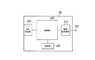
- FIG. 7 is a block diagram of the UE. As illustrated in FIG. 7, the UE includes an antenna 201, a radio transmission / reception unit 210, a GPS (Global Positioning System) reception unit 220, a storage unit 230, and a control unit 240.
- GPS Global Positioning System
- the antenna 201 and the wireless transmission / reception unit 210 are used for transmission / reception of wireless signals.
- the GPS receiver 220 receives a GPS signal in order to obtain UE location information indicating the location of the UE.
- the storage unit 230 stores information used for control by the control unit 240.
- the control unit 240 performs processing in each layer described above and performs various controls described later.
- the control unit 240 acquires UE location information based on the output of the GPS receiving unit 220. However, when the UE does not have the GPS receiver 220, the UE location information may be acquired based on a radio signal received by the radio transceiver 210.
- the storage unit 230 stores a white list that is a list of GSG cells (specifically, a list of CSG IDs) to which the UE has access rights.
- the storage unit 230 stores GSG cell location information indicating the location of the GSG cell to which the UE has access rights. The GSG cell location information is used together with the UE location information for an autonomous search procedure for determining whether there is a GSG cell to which the UE has an access right in the vicinity of the UE.
- FIG. 8 shows an operation environment of the eNB and UE according to the present embodiment.
- a CSG cell operated at a frequency different from that of the macro cell is provided in the macro cell, and the UE in the RRC idle state is located in an overlapping portion between the macro cell and the CSG cell.
- the UE is a member UE of the CSG cell and has an access right to the CSG cell.
- the UE normally detects that it is in the vicinity of the CSG cell by, for example, an autonomous search procedure, and selects the CSG cell as a standby cell.
- the UE desires to receive MBMS data and selects the macro cell as a standby cell in order to receive MBMS data distributed by PTM from the macro cell.
- the UE when the uplink data to be transmitted by the UE exceeds a predetermined amount, the UE normally establishes an RRC connection with the macro cell selected as the standby cell. However, for example, when the load level of the macro cell is high, after the UE establishes the RRC connection with the macro cell, the quality of service received by the UE becomes low.
- the proximity information (Proximity indication indicating that the CSG cell having the access right is in the vicinity based on the result of the autonomous search procedure. )
- the macro cell can hand over the UE to the CSG cell.
- a CSG cell whose access right is limited to CSG members generally has a lower load level than a macro cell whose access right is not limited to CSG members. Therefore, the UE can receive a high-quality service after handover to the CSG cell.
- the macro cell recognizes that the CSG cell having the access right is in the vicinity of the UE, and the potential uplink data amount of the UE As soon as the RRC connection is established, the UE can be handed over to the CSG cell.
- FIG. 9 is a sequence diagram showing operations of the eNB and the UE in the operating environment shown in FIG.
- step S1 the UE in the RRC idle state has selected the macro cell as a standby cell, and has received MBMS data distributed by PTM from the macro cell.
- step S2 the UE detects that uplink data to be transmitted has occurred, and starts processing for establishing an RRC connection with the macro cell selected as the standby cell.
- the UE transmits a random access preamble via a physical random access channel (PRACH).
- PRACH physical random access channel
- the macro cell broadcasts (for example, SIB2) information on radio resources (PRACH resources) that can be used for transmission of the random access preamble, and the UE transmits the random access preamble using the PRACH resource.
- Each cell can use a plurality of preamble sequences.
- the plurality of preamble sequences include a preamble set # 1, a preamble set # 2, and other preamble sets.
- the UE uses preamble set # 1 if the amount of uplink data is large, and uses preamble set # 2 if the amount of uplink data is small.
- the other preamble sets are contention-free access preamble sets, and are designated from the source cell at the time of handover, for example.
- step S4 when the macro cell (eNB) receives the random access preamble from the UE, the macro cell (eNB) detects whether the preamble sequence of the random access preamble is the preamble set # 1 or # 2, and the uplink data of the UE Determine (estimate) the amount. Then, the macro cell (eNB) stores the determined uplink data amount.
- step S5 the macro cell (eNB) transmits a random access response, which is a response to the random access preamble, to the UE via the DL-SCH (see FIG. 5).
- the random access response includes, for example, timing correction information for aligning the timing between the UE and the macro cell, information indicating a radio resource used for the next UE message transmission, and the like.
- Steps S3 to S5 described above constitute a random access procedure.
- step S6 when requesting establishment of an RRC connection with the macro cell (eNB), the UE transmits an RRC connection request message generated in the RRC layer to the macro cell (eNB).
- the macro cell (eNB) transmits an RRC connection setup message for establishing the RRC connection to the UE.
- the macro cell (eNB) transmits a Proximity information request to the UE together with the RRC connection setup message.
- the Proximity information request is information requesting to transmit Proximity information indicating that there is a CSG cell that can be accessed in the vicinity of the UE (that is, a CSG cell to which the UE has an access right).
- the Proximity information request can be an information element (IE) of an RRC connection setup message.
- step S8 in response to reception of the RRC connection setup message from the macro cell (eNB), the UE transmits an RRC connection setup completion message indicating that the establishment of the RRC connection is completed to the macro cell (eNB).
- the Proximity information is sent together with the RRC connection setup completion message to the macro cell. Send to. If the Proximity information is the IE of the RRC connection / setup completion message, the overhead can be reduced compared to the case where the Proximity information is transmitted alone.
- Steps S6 to S8 described above constitute an RRC connection establishment procedure.
- the macro cell in response to reception of Proximity information from the UE, the macro cell (eNB) transmits an RRC connection Reconfiguration message including a CSG measurement configuration instructing measurement for the CSG cell to the UE.
- the CSG measurement configuration is information instructing measurement of the quality of the CSG cell reported by the proximity information.
- the information includes a measurement gap for measuring the quality of the CSG cell.
- step S10 the UE transmits an RRC connection reconfiguration completion message, which is an acknowledgment to the RRC connection reconfiguration message, to the macro cell (eNB).
- the UE performs quality measurement on the CSG cell according to the CSG measurement configuration received from the macro cell (eNB) in step S9.
- the UE transmits a measurement report for reporting the measurement result to the macro cell (eNB).
- the measurement report includes a physical identifier (PCI; Physical Cell Identifier) that identifies the CSG cell.
- PCI Physical Cell Identifier
- step S12 the macro cell (eNB) transmits information (SI request) for requesting acquisition of broadcast information (SI) to the UE.
- SI request information for requesting acquisition of broadcast information (SI)
- the UE receives and acquires broadcast information (SI) broadcast from the CSG cell (HeNB).
- the broadcast information (SI) includes CGI (Cell Global Identity), TAI (Tracking Area Identity), CSG ID, and the like.
- step S14 the UE sends a measurement report including the broadcast information (SI) acquired in step S13 and information (Member Indication) indicating whether or not it has an access right to the specific cell (whether or not it is a CSG member). It transmits to a macro cell (eNB).
- SI broadcast information
- Member Indication information indicating whether or not it has an access right to the specific cell (whether or not it is a CSG member). It transmits to a macro cell (eNB).
- eNB macro cell
- step S15 the macro cell (eNB) determines whether or not to perform handover of the UE to the CSG cell based on the uplink data amount of the UE determined in step S4 and the measurement report received from the UE in step S14. Judging.
- the handover of the UE to the CSG cell is performed. If not, it is determined not to perform handover of the UE to the CSG cell.
- the following processing is executed when it is determined that the UE is handed over to the CSG cell.
- step S16 the macro cell (eNB), the CSG cell (HeNB), and the UE perform a handover procedure from the macro cell (eNB) to the CSG cell (HeNB).
- eNB macro cell
- HeNB CSG cell
- UE perform a handover procedure from the macro cell (eNB) to the CSG cell (HeNB).
- a specific example of the handover procedure will be described later.
- the CSG cell (HeNB) distributes the MBMS data to the UE by PTP in step S17.
- FIG. 10 is a sequence diagram illustrating a specific example of the handover procedure.
- Step S161 the macro cell (eNB) transmits a handover request for requesting handover to the CSG cell (HeNB) to the MME. .
- step S162 the MME determines whether or not to permit access of the UE to the CSG cell (HeNB).
- HeNB CSG cell
- Step S163 and Step S164 the MME transmits a handover request for requesting a handover to the CSG cell (HeNB) to the CSG cell (HeNB) via the HeNB GW.
- step S165 the CSG cell (HeNB) secures radio resources for the UE 10.
- step S166 and step S167 the CSG cell (HeNB) transmits an acknowledgment to the handover request received from the MME to the MME via the HeNB GW.
- step S168 and step S169 the MME transmits a handover instruction for instructing handover to the CSG cell (HeNB) to the UE via the macro cell (eNB).
- HeNB CSG cell
- eNB macro cell
- Step S6 for transmitting an RRC connection request message to the macro cell
- Step S7 for transmitting an RRC connection setup message for establishing an RRC connection to the UE in response to the RRC connection request message from the UE
- Step S8 of transmitting an RRC connection setup completion message indicating that the establishment of the RRC connection is completed in response to the RRC connection setup message from the macro cell.
- step S6 the macro cell transmits a Proximity information request to the UE together with the RRC connection setup message.
- the Proximity information request is information requesting to transmit Proximity information indicating that there is an accessible CSG cell in the vicinity of the UE.
- step S8 if there is an accessible CSG cell in the vicinity of the UE, the UE transmits Proximity information together with the RRC connection setup complete message to the macro cell.
- the eNB that manages the macro cell can grasp whether there is an accessible CSG cell in the vicinity of the UE. Therefore, when there is an accessible CSG cell in the vicinity of the UE, when the load level of the macro cell is high, the UE can be handed over to the CSG cell immediately after establishing the RRC connection between the macro cell and the UE. , Degradation of service quality in the UE can be suppressed.
- the UE when the macro cell receives Proximity information from the UE, the UE transmits a CSG measurement configuration instructing measurement to the CSG cell to the UE, and the UE receives the CSG from the macro cell.
- the step S11 for transmitting the measurement report for reporting the result of the measurement to the macro cell, and the eNB managing the macro cell based on the measurement report from the UE
- step 12 for determining whether or not to perform handover from the macro cell to the CSG cell.
- the eNB that manages the macro cell determines whether to perform handover from the macro cell to the CSG cell based on the uplink data amount of the UE estimated in the random access procedure in addition to the measurement report from the UE. Judging.
- the eNB that manages the macro cell determines that the handover from the macro cell to the CSG cell is performed when there is no free radio resource sufficient to transmit the uplink data amount of the UE satisfactorily. Therefore, it is possible to more reliably suppress a decrease in service quality at the UE.
- the HeNB that manages the CSG cell delivers MBMS data to the UE by PTP (unicast) after the handover of the UE is completed.
- the UE that has received MBMS data from the macro cell by PTM before the handover can receive the MBMS data by PTP even after the handover is completed. Therefore, continuity of MBMS data delivery to the UE can be guaranteed.
- the general cell is a macro cell and the specific cell is a CSG cell has been described, but the general cell may be a pico cell smaller than the macro cell.
- the specific cell may be a hybrid cell.
- the hybrid cell is regarded as a CSG cell from UEs belonging to the CSG, and is regarded as an open cell from UEs not belonging to the CSG. Therefore, the hybrid cell can be regarded as a kind of CSG cell.
- the LTE system has been described as an example, but the present invention may be applied to other communication standards such as UMTS (Universal Mobile Telecommunication System).
- UMTS Universal Mobile Telecommunication System
- the present invention is useful in the field of wireless communication such as mobile communication.
Landscapes
- Engineering & Computer Science (AREA)
- Computer Networks & Wireless Communication (AREA)
- Signal Processing (AREA)
- Mobile Radio Communication Systems (AREA)
Abstract
Description
MBMSデータのPTM配信をサポートする一般セル(例えば、マクロセル)と、前記MBMSデータのPTM配信をサポートしない特定セル(例えば、CSGセル)と、を含む移動通信システムにおける通信制御方法は、アイドル状態で前記一般セルを待ち受けセルとして選択しているユーザ端末(UE)が、前記一般セルとの接続(例えば、RRCコネクション)の確立を要求する際に、接続確立要求メッセージ(例えば、RRCコネクション要求メッセージ)を前記一般セルに送信するステップAと、前記一般セルが、前記ユーザ端末からの前記接続確立要求メッセージに応じて、前記接続を確立するための接続確立メッセージ(例えば、RRCコネクション・セットアップメッセージ)を前記ユーザ端末に送信するステップBと、前記ユーザ端末が、前記一般セルからの前記接続確立メッセージに応じて、前記接続の確立が完了したことを示す確立完了メッセージ(例えば、RRCコネクション・セットアップ完了メッセージ)を送信するステップCと、を有する。
本実施形態においては、リリース10以降の3GPP規格(すなわち、LTE Advanced)に基づいて構成される移動通信システム(以下、「LTEシステム」と称する)を例に説明する。
図1は、LTEシステムの構成を示す。図1に示すように、LTEシステムは、E-UTRAN(Evolved-UMTS Terrestrial Radio Access Network)と、UE(User Equipment)と、EPC(Evolved Packet Core)と、を有する。
MBMSは、同報型配信を実現するベアラサービスであり、MBMSデータの受信を望む複数のUEに対して、共通のベアラで一斉にMBMSデータを配信する方式である。
図6は、eNBのブロック図である。HeNBは、eNBと同様のブロック構成を有するため、ここではeNB及びHeNBを代表してeNBの構成を説明する。
図8は、本実施形態に係るeNB及びUEの動作環境を示す。
以上説明したように、本実施形態に係る通信制御方法は、アイドル状態でマクロセルを待ち受けセルとして選択しているUEが、マクロセルとのRRCコネクションの確立を要求する際に、RRCコネクション要求メッセージをマクロセルに送信するステップS6と、マクロセルが、UEからのRRCコネクション要求メッセージに応じて、RRCコネクションを確立するためのRRCコネクション・セットアップメッセージをUEに送信するステップS7と、UEが、マクロセルからのRRCコネクション・セットアップメッセージに応じて、RRCコネクションの確立が完了したことを示すRRCコネクション・セットアップ完了メッセージを送信するステップS8と、を有する。
この開示の一部をなす論述及び図面はこの発明を限定するものであると理解すべきではない。この開示から当業者には様々な代替実施形態、実施例及び運用技術が明らかとなる。
Claims (6)
- MBMSデータのPTM配信をサポートする一般セルと、前記MBMSデータのPTM配信をサポートしない特定セルと、を含む移動通信システムにおける通信制御方法であって、
アイドル状態で前記一般セルを待ち受けセルとして選択しているユーザ端末が、前記一般セルとの接続の確立を要求する際に、接続確立要求メッセージを前記一般セルに送信するステップAと、
前記一般セルが、前記ユーザ端末からの前記接続確立要求メッセージに応じて、前記接続を確立するための接続確立メッセージを前記ユーザ端末に送信するステップBと、
前記ユーザ端末が、前記一般セルからの前記接続確立メッセージに応じて、前記接続の確立が完了したことを示す確立完了メッセージを送信するステップCと、を有し、
前記ステップBにおいて、前記一般セルは、前記接続確立メッセージと共に通知要求情報を前記ユーザ端末に送信し、
前記通知要求情報は、前記ユーザ端末の近傍に前記特定セルが存在していれば、その旨の近傍通知を送信するよう要求する情報であり、
前記ステップCにおいて、前記ユーザ端末は、前記ユーザ端末の近傍に前記特定セルが存在していれば、前記確立完了メッセージと共に前記近傍通知を前記一般セルに送信することを特徴とする通信制御方法。 - 前記一般セルが、前記ユーザ端末からの前記近傍通知を受信した場合に、前記特定セルに対する測定を指示する測定指示を前記ユーザ端末に送信するステップDと、
前記ユーザ端末が、前記一般セルからの前記測定指示に応じて、前記特定セルに対する測定を行った後、当該測定の結果を報告するための測定報告を前記一般セルに送信するステップEと、
前記一般セルを管理する一般基地局が、前記ユーザ端末からの前記測定報告に基づいて、前記一般セルから前記特定セルへのハンドオーバを行うか否かを判断するステップFと、
をさらに有することを特徴とする請求項1に記載の通信制御方法。 - 前記ステップAよりも前に、前記ユーザ端末から前記一般セルへのランダムアクセス手順を行うステップをさらに有し、
前記ステップFにおいて、前記一般基地局は、前記ユーザ端末からの前記測定報告に加えて、前記ランダムアクセス手順において推測される前記ユーザ端末の上りリンクデータ量に基づいて、前記一般セルから前記特定セルへの前記ユーザ端末のハンドオーバを行うか否かを判断することを特徴とする請求項2に記載の通信制御方法。 - 前記特定セルは、前記一般セルの周波数と異なる周波数で運用されるCSGセルであることを特徴とする請求項1に記載の通信制御方法。
- MBMSデータのPTM配信をサポートする一般セルと、前記MBMSデータのPTM配信をサポートしない特定セルと、を含む移動通信システムにおいて、前記一般セルを管理する基地局であって、
アイドル状態で前記一般セルを待ち受けセルとして選択しているユーザ端末から、前記一般セルとの接続の確立を要求する際に、接続確立要求メッセージを受信する受信部と、
前記ユーザ端末からの前記接続確立要求メッセージに応じて、前記接続を確立するための接続確立メッセージを前記ユーザ端末に送信する送信部と、を有し、
前記送信部は、前記接続確立メッセージと共に通知要求情報を前記ユーザ端末に送信し、
前記通知要求情報は、前記ユーザ端末の近傍に前記特定セルが存在していれば、その旨の近傍通知を送信するよう要求する情報であることを特徴とする基地局。 - MBMSデータのPTM配信をサポートする一般セルと、前記MBMSデータのPTM配信をサポートしない特定セルと、を含む移動通信システムにおけるユーザ端末であって、
アイドル状態で前記一般セルを待ち受けセルとして選択している際に、前記一般セルから、前記ユーザ端末と前記一般セルとの接続を確立するための接続確立メッセージを受信する受信部と、
前記一般セルからの前記接続確立メッセージに応じて、前記接続の確立が完了したことを示す確立完了メッセージを送信する送信部と、を有し、
前記送信部は、前記ユーザ端末の近傍に前記特定セルが存在していれば、その旨の近傍通知を前記確立完了メッセージと共に前記一般セルに送信することを特徴とするユーザ端末。
Priority Applications (3)
| Application Number | Priority Date | Filing Date | Title |
|---|---|---|---|
| JP2013555338A JP5795811B2 (ja) | 2012-01-27 | 2013-01-25 | 通信制御方法、基地局、及びユーザ端末 |
| EP13741329.0A EP2822323A4 (en) | 2012-01-27 | 2013-01-25 | COMMUNICATION CONTROL PROCEDURE, BASIC STATION AND USER DEVICE |
| US14/373,489 US9560677B2 (en) | 2012-01-27 | 2013-01-25 | Communication control method, base station, and user terminal |
Applications Claiming Priority (2)
| Application Number | Priority Date | Filing Date | Title |
|---|---|---|---|
| US201261591479P | 2012-01-27 | 2012-01-27 | |
| US61/591,479 | 2012-01-27 |
Publications (1)
| Publication Number | Publication Date |
|---|---|
| WO2013111888A1 true WO2013111888A1 (ja) | 2013-08-01 |
Family
ID=48873599
Family Applications (1)
| Application Number | Title | Priority Date | Filing Date |
|---|---|---|---|
| PCT/JP2013/051668 WO2013111888A1 (ja) | 2012-01-27 | 2013-01-25 | 通信制御方法、基地局、及びユーザ端末 |
Country Status (4)
| Country | Link |
|---|---|
| US (1) | US9560677B2 (ja) |
| EP (1) | EP2822323A4 (ja) |
| JP (1) | JP5795811B2 (ja) |
| WO (1) | WO2013111888A1 (ja) |
Cited By (1)
| Publication number | Priority date | Publication date | Assignee | Title |
|---|---|---|---|---|
| JP2020031446A (ja) * | 2014-04-30 | 2020-02-27 | 株式会社Nttドコモ | 端末、及び通信アクセス方法 |
Families Citing this family (6)
| Publication number | Priority date | Publication date | Assignee | Title |
|---|---|---|---|---|
| JP5885857B2 (ja) * | 2011-12-19 | 2016-03-16 | テレフオンアクチーボラゲット エル エム エリクソン(パブル) | ネットワークノード及びネットワークノードにおける方法 |
| JP6043565B2 (ja) * | 2012-09-28 | 2016-12-14 | 株式会社Nttドコモ | 移動通信システム、無線基地局、移動管理ノード及び移動局 |
| WO2016167606A1 (ko) * | 2015-04-15 | 2016-10-20 | 엘지전자 주식회사 | 무선 통신 시스템에서 단말이 피드백을 수행하는 방법 및 이를 위한 장치 |
| WO2019031861A1 (en) * | 2017-08-09 | 2019-02-14 | Lg Electronics Inc. | METHOD FOR EXECUTING A RANDOM ACCESS PROCEDURE AND DEVICE SUPPORTING SAID METHOD |
| CN109600783A (zh) * | 2017-09-30 | 2019-04-09 | 中国移动通信有限公司研究院 | 小区测量值上报方法、小区测量值接收方法和设备 |
| CN114501340B (zh) * | 2020-10-23 | 2023-03-31 | 中国移动通信有限公司研究院 | Mbs接收方法、发送方法、装置、终端及基站 |
Citations (2)
| Publication number | Priority date | Publication date | Assignee | Title |
|---|---|---|---|---|
| JP2009207108A (ja) * | 2008-02-01 | 2009-09-10 | Panasonic Corp | 基地局、無線通信システム、およびハンドオーバ方法 |
| JP2011234039A (ja) * | 2010-04-26 | 2011-11-17 | Sharp Corp | 移動局装置、通信システム、セル再選択方法および集積回路 |
Family Cites Families (6)
| Publication number | Priority date | Publication date | Assignee | Title |
|---|---|---|---|---|
| JP5538802B2 (ja) * | 2008-11-04 | 2014-07-02 | 三菱電機株式会社 | 通信方法、移動体通信システム、移動端末および基地局制御装置 |
| JP5159735B2 (ja) * | 2009-09-11 | 2013-03-13 | シャープ株式会社 | 無線通信システム、基地局装置、移動局装置および通信方法 |
| WO2011039960A1 (ja) * | 2009-10-02 | 2011-04-07 | 三菱電機株式会社 | 移動体通信システム |
| CN102714821B (zh) * | 2010-01-08 | 2015-12-16 | 交互数字专利控股公司 | 在连接模式中对h(e)nb出站移动性和h(e)nb间移动性测量进行估计和报告 |
| KR20130079564A (ko) * | 2010-09-28 | 2013-07-10 | 리서치 인 모션 리미티드 | Ue가 주택/기업 네트워크 커버리지 밖으로 이동할 때 로컬 gw와의 연결을 해제시키는 방법 및 장치 |
| US9173192B2 (en) * | 2011-03-17 | 2015-10-27 | Qualcomm Incorporated | Target cell selection for multimedia broadcast multicast service continuity |
-
2013
- 2013-01-25 US US14/373,489 patent/US9560677B2/en active Active
- 2013-01-25 EP EP13741329.0A patent/EP2822323A4/en not_active Withdrawn
- 2013-01-25 JP JP2013555338A patent/JP5795811B2/ja active Active
- 2013-01-25 WO PCT/JP2013/051668 patent/WO2013111888A1/ja active Application Filing
Patent Citations (2)
| Publication number | Priority date | Publication date | Assignee | Title |
|---|---|---|---|---|
| JP2009207108A (ja) * | 2008-02-01 | 2009-09-10 | Panasonic Corp | 基地局、無線通信システム、およびハンドオーバ方法 |
| JP2011234039A (ja) * | 2010-04-26 | 2011-11-17 | Sharp Corp | 移動局装置、通信システム、セル再選択方法および集積回路 |
Non-Patent Citations (3)
| Title |
|---|
| 3RD GENERATION PARTNERSHIP PROJECT: "WID: Service continuity improvements for MBMS for LTE (3GPP Contribution RP-111374)", TSG-RAN MEETING 51, 13 September 2011 (2011-09-13) - 16 September 2011 (2011-09-16) |
| KYOCERA: "MBMS sevice continuity for inbound mobility to non-MBMS capable cells", 3GPP TSG-RAN WG2 #75 R2-114095, 26 August 2011 (2011-08-26), XP050539957 * |
| See also references of EP2822323A4 |
Cited By (2)
| Publication number | Priority date | Publication date | Assignee | Title |
|---|---|---|---|---|
| US11582724B2 (en) | 2013-04-30 | 2023-02-14 | Ntt Docomo, Inc. | User equipment, base station, communication access method, and communication method |
| JP2020031446A (ja) * | 2014-04-30 | 2020-02-27 | 株式会社Nttドコモ | 端末、及び通信アクセス方法 |
Also Published As
| Publication number | Publication date |
|---|---|
| JPWO2013111888A1 (ja) | 2015-05-11 |
| JP5795811B2 (ja) | 2015-10-14 |
| EP2822323A1 (en) | 2015-01-07 |
| EP2822323A4 (en) | 2016-01-13 |
| US9560677B2 (en) | 2017-01-31 |
| US20140362757A1 (en) | 2014-12-11 |
Similar Documents
| Publication | Publication Date | Title |
|---|---|---|
| JP6416431B2 (ja) | ネットワーク装置、通信方法、プロセッサ及び基地局 | |
| JP5997247B2 (ja) | 移動通信方法、ユーザ端末、基地局、及びプロセッサ | |
| JP6184566B2 (ja) | 通信制御方法、ユーザ端末、及び装置 | |
| JP5795811B2 (ja) | 通信制御方法、基地局、及びユーザ端末 | |
| EP2302969A1 (en) | Method of handling mobility in multimedia broadcast multicast service single frequency network in a wireless communication system and related communication device | |
| US20160381517A1 (en) | Method and apparatus for transmitting unicast request indication in wireless communication system | |
| JP6140271B2 (ja) | 通信制御方法、ユーザ端末、及びプロセッサ | |
| WO2016047512A1 (ja) | 基地局及びユーザ端末 | |
| JP7259136B2 (ja) | 通信制御方法、基地局、ユーザ装置及びプロセッサ | |
| WO2024071245A1 (ja) | 通信方法 | |
| WO2024034569A1 (ja) | 通信方法 | |
| WO2013111889A1 (ja) | 通信制御方法及びユーザ端末 | |
| WO2014021462A1 (ja) | 移動通信システム、ユーザ端末、及びプロセッサ |
Legal Events
| Date | Code | Title | Description |
|---|---|---|---|
| 121 | Ep: the epo has been informed by wipo that ep was designated in this application |
Ref document number: 13741329 Country of ref document: EP Kind code of ref document: A1 |
|
| ENP | Entry into the national phase |
Ref document number: 2013555338 Country of ref document: JP Kind code of ref document: A |
|
| WWE | Wipo information: entry into national phase |
Ref document number: 14373489 Country of ref document: US |
|
| NENP | Non-entry into the national phase |
Ref country code: DE |
|
| REEP | Request for entry into the european phase |
Ref document number: 2013741329 Country of ref document: EP |
|
| WWE | Wipo information: entry into national phase |
Ref document number: 2013741329 Country of ref document: EP |