US11582724B2 - User equipment, base station, communication access method, and communication method - Google Patents
User equipment, base station, communication access method, and communication method Download PDFInfo
- Publication number
- US11582724B2 US11582724B2 US15/306,370 US201515306370A US11582724B2 US 11582724 B2 US11582724 B2 US 11582724B2 US 201515306370 A US201515306370 A US 201515306370A US 11582724 B2 US11582724 B2 US 11582724B2
- Authority
- US
- United States
- Prior art keywords
- base station
- user equipment
- random access
- reference signal
- terminal
- Prior art date
- Legal status (The legal status is an assumption and is not a legal conclusion. Google has not performed a legal analysis and makes no representation as to the accuracy of the status listed.)
- Active, expires
Links
Images


Classifications
-
- H—ELECTRICITY
- H04—ELECTRIC COMMUNICATION TECHNIQUE
- H04W—WIRELESS COMMUNICATION NETWORKS
- H04W72/00—Local resource management
- H04W72/04—Wireless resource allocation
-
- H—ELECTRICITY
- H04—ELECTRIC COMMUNICATION TECHNIQUE
- H04W—WIRELESS COMMUNICATION NETWORKS
- H04W74/00—Wireless channel access, e.g. scheduled or random access
- H04W74/08—Non-scheduled or contention based access, e.g. random access, ALOHA, CSMA [Carrier Sense Multiple Access]
- H04W74/0833—Non-scheduled or contention based access, e.g. random access, ALOHA, CSMA [Carrier Sense Multiple Access] using a random access procedure
-
- H—ELECTRICITY
- H04—ELECTRIC COMMUNICATION TECHNIQUE
- H04W—WIRELESS COMMUNICATION NETWORKS
- H04W16/00—Network planning, e.g. coverage or traffic planning tools; Network deployment, e.g. resource partitioning or cells structures
- H04W16/24—Cell structures
- H04W16/28—Cell structures using beam steering
-
- H—ELECTRICITY
- H04—ELECTRIC COMMUNICATION TECHNIQUE
- H04W—WIRELESS COMMUNICATION NETWORKS
- H04W74/00—Wireless channel access, e.g. scheduled or random access
- H04W74/08—Non-scheduled or contention based access, e.g. random access, ALOHA, CSMA [Carrier Sense Multiple Access]
-
- H—ELECTRICITY
- H04—ELECTRIC COMMUNICATION TECHNIQUE
- H04B—TRANSMISSION
- H04B7/00—Radio transmission systems, i.e. using radiation field
- H04B7/02—Diversity systems; Multi-antenna system, i.e. transmission or reception using multiple antennas
- H04B7/04—Diversity systems; Multi-antenna system, i.e. transmission or reception using multiple antennas using two or more spaced independent antennas
- H04B7/06—Diversity systems; Multi-antenna system, i.e. transmission or reception using multiple antennas using two or more spaced independent antennas at the transmitting station
- H04B7/0613—Diversity systems; Multi-antenna system, i.e. transmission or reception using multiple antennas using two or more spaced independent antennas at the transmitting station using simultaneous transmission
- H04B7/0615—Diversity systems; Multi-antenna system, i.e. transmission or reception using multiple antennas using two or more spaced independent antennas at the transmitting station using simultaneous transmission of weighted versions of same signal
- H04B7/0617—Diversity systems; Multi-antenna system, i.e. transmission or reception using multiple antennas using two or more spaced independent antennas at the transmitting station using simultaneous transmission of weighted versions of same signal for beam forming
-
- H04W72/1284—
-
- H—ELECTRICITY
- H04—ELECTRIC COMMUNICATION TECHNIQUE
- H04W—WIRELESS COMMUNICATION NETWORKS
- H04W72/00—Local resource management
- H04W72/20—Control channels or signalling for resource management
- H04W72/21—Control channels or signalling for resource management in the uplink direction of a wireless link, i.e. towards the network
-
- H—ELECTRICITY
- H04—ELECTRIC COMMUNICATION TECHNIQUE
- H04W—WIRELESS COMMUNICATION NETWORKS
- H04W88/00—Devices specially adapted for wireless communication networks, e.g. terminals, base stations or access point devices
- H04W88/02—Terminal devices
-
- H—ELECTRICITY
- H04—ELECTRIC COMMUNICATION TECHNIQUE
- H04W—WIRELESS COMMUNICATION NETWORKS
- H04W88/00—Devices specially adapted for wireless communication networks, e.g. terminals, base stations or access point devices
- H04W88/08—Access point devices
Definitions
- the present invention relates to a base station and user equipment of a radio communication system.
- the MIMO technology has been adopted that enhances system capacity, a cell edge user throughput, and so forth.
- the heterogeneous network technology has been adopted that achieves high quality communication by reducing inter-cell interference, while allowing different types of base stations (e.g., macro cells and small cells) to coexist.
- the massive MIMO is the large-scale MIMO where a large number of antennas (e.g., 100 elements) are used, and the massive MIMO can cause the electric field intensity to be concentrated in a narrow region, so that interference between users can be reduced.
- the heterogeneous network in order to compensate for the propagation loss in the high frequency band, it has been studied to implement beam forming using a plurality of antennas, not only for a downlink, but also for an uplink.
- Patent Document 1 Japanese Unexamined Patent Publication No. 2013-219507
- the present invention is achieved in view of the above-described point, and an object is to provide technology that allows, in a radio communication system including a base station that implements beam forming and user equipment, the base station to efficiently determine a favorable beam.
- user equipment for communicating with a base station in a radio communication system including the base station and the user equipment, the user equipment including a receiver that measures received power of reference signals associated with a plurality of different identification information items, the reference signals being transmitted from the base station, and that selects a specific reference signal based on a measurement result; and a transmitter that transmits a random access signal including a preamble sequence, the preamble sequence corresponding to the identification information item of the reference signal selected by the receiver.
- a base station for communicating with user equipment in a radio communication system including the base station and the user equipment, the base station including a transmitter that transmits reference signals associated with a plurality of different identification information items; and a receiver that receives, from the user equipment, a random access signal including a preamble sequence, the preamble sequence corresponding to an identification information item of a specific reference signal received by the user equipment, wherein the transmitter transmits, to the user equipment, a control signal based on the identification information item obtained from the random access signal received by the receiver.
- the technology can be provided that allows, in a radio communication system including a base station that implements beam forming and user equipment, the base station to efficiently determine a favorable beam.
- FIG. 1 is an overall configuration diagram of a radio communication system according to one or more embodiments of the present invention
- FIG. 2 is a diagram illustrating an application example of user equipment implementing beam forming according to one or more embodiments of the present invention
- FIG. 3 is a diagram illustrating an example of mapping of a PRACH according to one or more embodiments of the present invention
- FIG. 4 is a sequence diagram illustrating an example of an operation of the radio communication system according to one or more embodiments of the present invention.
- FIG. 5 is a diagram illustrating a beam search by user equipment 20 at step S 101 of FIG. 4 ;
- FIG. 6 is a diagram illustrating PRACH reception by a base station 12 at step S 102 of FIG. 4 ;
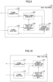
- FIG. 7 is a diagram illustrating EPDCCH transmission by the base station 12 at step S 103 of FIG. 4 ;
- FIG. 8 is a diagram illustrating an example of signal mapping during carrier aggregation according to one or more embodiments of the present invention.
- FIG. 9 is a functional configuration diagram of the user equipment 20 according to one or more embodiments of the present invention.
- FIG. 10 is a functional configuration diagram of the base station 12 according to one or more embodiments of the present invention.
- a radio communication system is a system based on a scheme that conforms to the LTE, and that the OFDM is used for the downlink and the SC-FDMA is used for an uplink; however, the present invention is not limited to this, and, for example, the OFDM may be used for both uplink and downlink.
- the present invention can be applied to a scheme other than the LTE.
- LTE Long Term Evolution
- FIG. 1 illustrates an overall configuration diagram of a radio communication system according to one or more embodiments of the present invention.
- the radio communication system according to one or more embodiments of the present invention includes a macro base station 10 that forms a macro cell; and base stations 11 and 12 that are located within a coverage area of the macro cell. Additionally, in FIG. 1 , user equipment 20 is illustrated that communicates with the macro base station 10 and the base stations 11 and 12 .
- the radio communication system adopts a configuration such that macro coverage is reserved by the macro base station 10 in a low frequency band, and traffic in a small area (e.g., a hot spot) is absorbed by the base stations 11 and 12 in a high frequency band; however, such an allocation of frequency bands is merely an example, and it is not limited to this.
- the base stations 11 and 12 are provided with functions of the massive MIMO, respectively, so that various types of beams can be formed, which are from broad beams to narrow beams.
- a plurality of precoded reference signals (which are referred to as “discovery signals” in the embodiments) is transmitted, from the base stations 11 and 12 , through respective beams (a plurality of antenna ports).
- the fact that the reference signal is precoded means that, for each antenna port, a transmit signal is multiplied by a weight, so that the reference signal is transmitted by a beam with a certain width (i.e., with directivity).
- discovery signals are transmitted from the base station 12 through a beam 2 - 1 , a beam 2 - 2 , and a beam 2 - 3 , respectively.
- the configuration is illustrated where the macro base station 10 exists; however, a configuration may be adopted where the macro base station 10 does not exist.
- the beams formed by the base stations 11 and 12 may be hierarchical.
- the base stations 11 and 12 may form, within each beam illustrated in FIG. 1 , a plurality of narrow beams.
- the user equipment 20 can operate in such a manner that, by receiving reference signals transmitted through a plurality of narrower beams in the beam # 2 - 2 (belonging to the beam # 2 - 2 ), the most favorable beam is selected among the plurality of narrow beams.
- the base stations 11 and 12 can form, also at the receiving side, the beams as illustrated in FIG. 1 , and hierarchical beams, as described above.
- To form the beams at the receiving side means that, for each antenna port, a received signal is multiplied by a weight, so that the signal is received through a beam with a certain beam width (i.e., with directivity).
- a discovery signal includes an identification information item for identifying the discovery signal.
- the identification information items identifies the discovery signal, and also identifies a beam, so that it is referred to as a beam ID, hereinafter.
- the user equipment 20 measures received power of each discovery signal transmitted from the base stations 11 and 12 (beam search); and the user equipment 20 operates to transmit a PRACH including a preamble sequence (preamble sequence) corresponding the beam ID of the discovery signal that is received with the highest received power.
- preamble sequence preamble sequence
- the details of operation including this operation are described below.
- a quantity measured at the beam search is not limited to the received power, and it may be another quantity (e.g., reception quality). Additionally, the received power and another quantity may be collectively referred to as the reception quality.
- the user equipment 20 can simultaneously communicate, for example, with the macro base station 10 that forms the macro cell (e.g., a PCell), and the base stations 11 and 12 that form small cells (e.g., SCells) by applying carrier aggregation; and the user equipment can also communicate only with a single base station.
- the macro base station 10 that forms the macro cell (e.g., a PCell)
- the base stations 11 and 12 that form small cells (e.g., SCells) by applying carrier aggregation
- SCells small cells
- the user equipment 20 in one or more embodiments of the present invention may include a plurality of antennas, and may include a function to execute uplink MIMO transmission. Namely, the user equipment 20 can execute uplink beam forming, and uplink multiple rank transmission. However, in one or more embodiments of the present invention, is not mandatory to execute transmission by using a plurality of antennas for the uplink.
- UE user equipment
- MTC terminals low-cost MTC terminals and so forth.
- user equipment including a MIMO transmission function with approximately four antennas becomes the mainstream.
- user equipment including a Massive MIMO function with 16 or more antennas may be used.
- a communication device that is to be installed in a means of public transportation, such as a train, user equipment with a role of a relay device in the backhaul of communication between base stations, and so forth, can be considered.
- a PRACH is described that is to be transmitted by the user equipment 20 in the uplink in one or more embodiments of the present invention.
- the PRACH is a channel for transmitting a preamble sequence during initial access to a base station; however, for the PRACH, an expression “transmit the PRACH” may be used in the meaning that the PRACH is a signal including the preamble sequence.
- the PRACH may also be referred to as a “random access signal.”
- the PRACH in one or more embodiments of the present invention is a channel to be transmitted when the user equipment 20 executes searching for beams transmitted from the base stations 11 and 12 , and when the user equipment 20 initially accesses the base stations 11 and 12 , after detecting the beam with the highest received power.
- the PRACH includes a scheduling request function; and the base station that receives the PRACH operates to allocate, to the user equipment 20 , a radio resource for uplink data transmission, and to transmit, to the user equipment 20 , the allocation information (UL grant) through the EPDCCH (or the PDCCH, which is assumed to be the EPDCCH, hereinafter).
- the resource to be applied is a time-frequency resource, such as a resource block; and for a case where the TDD is to be applied, the resource to be applied is a resource, such as a UL subframe.
- a measurement report (measurement report, which includes the received power, the reception quality, and so forth) may be transmitted through the PRACH.
- discovery signals to be transmitted through respective beams from the base stations 11 and 12 which are illustrated in FIG. 1 , each includes a beam ID associated with the beam.
- the beam IDs are associated with the preamble sequences in advance; and the user equipment 20 maintains the information on the association between the beam IDs and the preamble sequences (the information indicating which beam ID corresponds to which preamble sequence).
- the information on the association may be the information to be signaled, in advance, from the macro base station 10 to the user equipment 20 , or the information that is to be maintained by the user equipment 20 by another method.
- each of the base stations 11 and 12 maintains, at least, information on the association between the beam ID, which is to be used by the base station itself, and the preamble sequence.
- the user equipment UE transmits a PRACH including a preamble sequence corresponding to the beam ID of the discovery signal with the highest received power.
- a resource e.g., a frequency position
- each user equipment maintains, in advance, the information on the resource for transmitting the PRACH, which corresponds to the user equipment itself.
- each of the base stations 11 and 12 maintains, in advance, the information on the association between the resource for receiving the PRACH (which is the resource for sending when it is viewed from the user equipment) and the user equipment identification information, so that each of the base stations 11 and 12 can recognize, from the receiving resource of the PRACH that has been received (the PRACH with which the preamble sequence has been obtained), the user equipment identification information of the user equipment that is the sender of the PRACH, and after that, each of the base stations 11 and 12 can transmit a control signal, such as the EPDCCH, to the user equipment.
- the above-described user equipment identification information can be, for example, the UE-ID (e.g., the C-RNTI), or the UE-specific VCID; however, it is not limited to these.
- FIG. 3 illustrates an example of a resource for transmitting the PRACH.
- a PRACH resource for a user 1 is allocated to a certain frequency band of a specific subframe, and a PRACH resource for a user 2 is allocated to another frequency band.
- FIG. 4 illustrates the base station 12 out of the base station 11 and the base station 12 .
- the user equipment 20 measures, for example, for each discovery signal which may be received, the received power (this operation may be referred to as monitoring); and the user equipment 20 detects (receives) a specific discovery signal (one or more).
- a specific discovery signal one or more.
- FIG. 5 illustrates an image of step 101 .
- the base station 12 transmits, through a plurality of beams, a plurality of discovery signals, each including a respective different beam ID.
- the beam to be formed here can be a broad beam (the beam that is broader than narrow beams belonging to it).
- the user equipment may narrow down candidates by receiving auxiliary information (which is referred to as macro auxiliary information) from the macro base station 10 , and the user equipment 20 may detect the discovery signal transmitted from the base station 12 .
- the macro auxiliary information includes transmission timing, sequence information, a beam ID, and so forth of the discovery signal within the coverage of the macro cell.
- the user equipment 20 since the user equipment 20 recognizes the transmission timing and the beam ID of each of the discovery signals based on the macro auxiliary information received from the macro base station 10 , by monitoring narrowed down candidates by using these, the user equipment 20 receives each of the discovery signals transmitted from the base station 12 .
- the base station 12 may transmit the synchronization signal (e.g., PSS/SSS) separately from the discovery signal; or the discovery signal may have a function of the synchronization signal.
- the discovery signal has the function of the synchronization signal
- the user equipment 20 can achieve, by receiving the discovery signal, frequency synchronization and timing synchronization (e.g., symbol synchronization and frame synchronization) with the base station 12 .
- the discovery signal information required for communication in the coverage of the base station 12 (e.g., the minimum system information) may be received.
- the synchronization signal is received separately from the discovery signal, after achieving the frequency synchronization and the timing synchronization by the synchronization signal, the discovery signal is received.
- the user equipment 20 identifies the beam ID of the discovery signal with the highest received power, based on the measurement result of the received power. Note that, instead of identifying one beam ID with the highest received power, a predetermined number of beam IDs may be identified in a descending order.
- the user equipment 20 transmits the PRACH (step 102 of FIG. 4 ).
- the base station 12 receives the PRACH.
- the PRACH includes the preamble sequence associated with the beam ID of the beam with the large received power, which is identified in the above-described manner. Further, the PRACH is transmitted by the resource associated with the user equipment 20 .
- FIG. 6 illustrates an image of receiving, at step 102 , the PRACH by the base station 12 .
- the base station 12 receives the PRACH by using a beam that is narrower than the beam for the transmission, which is illustrated in FIG. 4 .
- the base station 12 since the PRACH includes a preamble sequence corresponding to the beam ID, the base station 12 detects the beam ID in the received PRACH; and the base station 12 identifies, among a plurality of narrow beams belonging to the beam corresponding to the beam ID (the broad beam), the beam with which the PRACH is received with the highest received power. For example, for a case where the beam ID is “1,” the received power is measured for each of the plurality of narrow beams belonging to the received beam (which is in the direction opposite to the transmission) corresponding to the transmit beam with “1,” and the beam is identified with which the PRACH is received with the highest received power.
- the TDD is applied. Namely, by the reciprocity, when a beam in a specific direction toward the user equipment is a favorable beam, it can be estimated that the beam that is obtained by reversing the direction (directed to the base station) is also a favorable beam. However, even for the FDD, the method described in this operation example can be applied. The reason is that, in the FDD, even if the frequencies are different in the uplink and downlink, for a favorable beam in the downlink direction, the uplink beam obtained by reversing it can be estimated to be a favorable beam.
- the base station 12 can quickly recognize a beam that is favorable for the user equipment 20 , and the base station 12 can properly narrow down the more narrower beam candidates.
- the base station 12 obtains, from the receiving resource of the PRACH received at step 102 , the user equipment identification information of the user equipment 20 , which is the sender that transmits the PRACH. Namely, the base station 12 maintains, in a storage unit, correspondence information between the PRACH resource and the user equipment identification information; and the base station 12 obtains the user equipment identification information corresponding to the receiving resource of the PRACH.
- the base station 12 allocates a UL resource to the user equipment 20 ; and the base station 12 transmits the UL grant including the allocation information (e.g., an RB) to the user equipment through the EPDCCH by using the narrow beam in the direction opposite to the direction of the identified narrow beam.
- Transmitting the EPDCCH to the user equipment 20 means to transmit the EPDCCH (a control signal) including the user equipment identification information.
- FIG. 7 illustrates a situation in this case.
- the user equipment 20 transmits UL data by using the allocated resource.
- the base station 12 transmits the discovery signal by the broad beam, that the base station 12 identifies the narrow beam during receiving the PRACH, and that the base station 12 transmits the EPDCCH by the beam that is opposite to the narrow beam; however, the base station 12 may transmit the EPDCCH by using a beam corresponding to the beam with the beam ID, which is identified by the PRACH. Namely, the EPDCCH may be transmitted by a beam with a width that is the same as that of the discovery signal.
- information on the size of the UL data may be included in the preamble sequence of the PRACH.
- the base station 12 can adjust the amount of the resource to be allocated to the user equipment 20 .
- reception quality information e.g., the CQI
- This CQI may be rough compared with the CQI that is used for normal reporting of the CQI.
- the base station 12 can transmit the EPDCCH by using a proper MCS.
- the user equipment 20 transmits the PRACH by not using a beam; however, the user equipment 20 may transmit the PRACH by using a plurality of beams.
- the user equipment 20 can execute communication with the base station 12 by carrier aggregation (CA), by using a plurality of component carriers (CCs) (the same for the base station 11 ).
- CA carrier aggregation
- CCs component carriers
- the PDSCH, the EPDCCH, the CSI-RS, and so forth are transmitted from the base station by each CC (all CCs); and, for the uplink, the PUSCH, the PUCCH, and the SRS (the sounding reference signal) are transmitted by each CC (all CCs).
- the synchronization signal e.g., PSS/SSS
- the downlink reference signals the discovery signals of the embodiments
- the PRACH may be transmitted by all the CCs, or by one CC.
- FIG. 8 illustrates an example of signal mapping to the CCs during the carrier aggregation. Note that, FIG. 8 is an example of the TDD where the uplink and downlink are time divided; however, the same mapping is possible, even for the FDD. For the case of FDD, it can be viewed, in FIG. 8 , that the frequencies of the CCs are different for the uplink and downlink.
- the PRACH is transmitted by the CC 1 , which is a single CC; and the CCs 2 , 3 , and 4 , which are the other CCs forming the carrier aggregation, do not transmit the PRACH.
- the synchronization signal (PSS/SSS) is transmitted by the CC 1 , which is the single CC; and it is not transmitted by the CCs 2 , 3 , and 4 , which are the other CCs forming the carrier aggregation.
- the downlink reference signals (the discovery signals in the embodiments) are transmitted by all the CCs.
- the subsequent process can be quickly executed.
- each device described below illustrates the configuration that is particularly related to one or more embodiments of the present invention, and each device includes functions of the user equipment/base station that can execute operations conforming to the LTE, for example.
- FIG. 9 illustrates a functional configuration diagram of the user equipment 20 .
- the user equipment 20 includes a signal transmitter 201 ; a signal receiver 202 ; a reception quality measurement unit 203 ; a control information storage unit 204 ; and a PRACH signal generator 205 .
- the signal transmitter 201 generates a lower layer signal from upper layer information, and transmits it by radio.
- the signal receiver 202 obtains, from the lower layer signal received by radio, the upper layer information.
- the signal receiver 202 receives control information from the base station 12 and the macro base station 10 ; stores it in the control information storage unit 204 ; and, at the same time, performs receiving operations based on the control information. For example, a downlink allocated resource can be received as the control information, and the receiving operation can be performed in accordance with the control information.
- the control information storage unit 204 stores various types of control information received from the base station 12 and the macro base station 10 .
- As the control information there are information on the correspondence between the beam ID and the preamble sequence, and the resource information for the PRACH transmission, for example.
- the reception quality measurement unit 203 measures reception quality (e.g., the received power, the CQI, and the rank) of the discovery signals received by the signal receiver 202 , and passes the measurement results to the PRACH signal generator 205 .
- reception quality e.g., the received power, the CQI, and the rank
- the PRACH signal generator 205 identifies the beam ID of the discovery signal with high received power from the measurement results obtained from the discovery signals of the respective beams; generates a preamble sequence corresponding to the beam ID; and passes it to the signal transmitter 201 .
- the signal transmitter 201 transmits the PRACH including the preamble sequence by using a resource associated with the user equipment 20 . Further, as described above, the PRACH may include the UL data amount, the CQI, and so forth.
- the signal transmitter 201 executes uplink data transmission in accordance with the control information (e.g., the UL allocation information) that is received by the signal receiver 202 and that is stored in the control information storage unit 204 .
- control information e.g., the UL allocation information
- FIG. 10 illustrates a functional configuration diagram of the base station 12 .
- the base station 12 includes a signal transmitter 121 ; a signal receiver 122 ; a reception quality measurement unit 123 ; and a control information generator 124 .
- the signal transmitter 121 generates a lower layer signal from upper layer information, and transmits it by radio.
- the signal receiver 122 obtains the upper layer information from the lower layer signal received by radio.
- the signal receiver 122 receives the PRACH transmitted from the user equipment 20 ; and, at the same time, the signal receiver 122 obtains a preamble sequence, and obtains a beam ID associated with the preamble sequence. Further, the signal receiver 122 obtains the user equipment identification information associated with the resource with which the PRACH is received.
- the correspondence information required for each of the above-described processes is stored in the storage unit of the base station 12 ; and the signal receiver 122 reads out necessary information from the storage unit.
- the received quality measurement unit 123 measures, for each PRACH (for each user equipment), and for each narrow beam belonging to a wide beam corresponding to the beam ID, received power of the PRACH (which may be reception quality other than the received power); identifies the narrow beam with the highest received power; and passes the information to the control information generator 124 .
- the control information generator 124 obtains allocation information by executing resource allocation to the user equipment; and generates control information including the allocation information and the above-described user information identification. Then, the control information is passed to the signal transmitter 121 , and the signal transmitter 121 is instructed to transmit a control signal including the control information (e.g., the EPDCCH) through the identified narrow beam; and the signal transmitter 121 transmits the control signal through the narrow beam.
- the control information e.g., the EPDCCH
- FIG. 9 and FIG. 10 are merely an example.
- the implementation method (specific arrangement of functional units) is not limited to a specific implementation method, provided that the process described in the embodiments can be implemented.
- the user equipment and the base station according to one or more embodiments of the present invention may also be configured as devices formed of the units described below.
- the user equipment in one or more embodiments of the present invention can be configured as user equipment for communicating with a base station, in a radio communication system including the base station and the user equipment, the user equipment including a receiver that measures received power of reference signals associated with a plurality of different identification information items, the reference signals being transmitted from the base station, and that selects a specific reference signal based on a measurement result; and a transmitter that transmits a random access signal including a preamble sequence, the preamble sequence corresponding to the identification information item of the reference signal selected by the receiver.
- the base station can efficiently determine a favorable beam.
- the transmitter can transmit the random access signal by using a radio resource associated with the user equipment.
- the base station can quickly recognize the user equipment that is a sender of the random access signal.
- the random access signal may include an amount of data to be transmitted by the user equipment in an uplink, and the random access signal may be transmitted to the base station, as a scheduling request.
- the random access signal By transmitting the random access signal as the scheduling request, the user equipment can start uplink data transmission with a small number of steps.
- the identification information items may be associated with respective beams for transmitting the reference signals.
- the base station can recognize a beam that is favorably received by the user equipment, and the base station can properly determine, based on the beam, the beam to be used for transmission to the user equipment.
- the base station in one or more embodiments of the present invention is configured as a base station for communicating with user equipment in a radio communication system including the base station and the user equipment, the base station including a transmitter that transmits reference signals associated with a plurality of different identification information items; and a receiver that receives, from the user equipment, a random access signal including a preamble sequence, the preamble sequence corresponding to an identification information item of a specific reference signal received by the user equipment, wherein the transmitter transmits, to the user equipment, a control signal based on the identification information item obtained from the random access signal received by the receiver.
- the base station can efficiently determine a favorable beam.
- the receiver can receive the random access signal by a radio resource that is associated with the user equipment; and the transmitter can transmit, to the user equipment, the control signal to which identification information of the user equipment is attached, the identification information of the user equipment being obtained based on the radio resource.
- the base station can quickly identify the user equipment that is a sender of the random access signal; and the base station can transmit the control signal (e.g., uplink allocation information) to the user equipment.
- the random access signal may be transmitted from the user equipment, as a scheduling request; and the transmitter may transmit, to the user equipment, the control signal including resource allocation information based on the scheduling request.
- the user equipment can start uplink data transmission with a small number of steps.
- a communication access method to be executed by user equipment that communicates with a base station in a radio communication system including the base station and the user equipment, the method including a reception step of measuring received power of reference signals associated with a plurality of different identification information items, the reference signals being transmitted from the base station, and selecting a specific reference signal based on a measurement result; and a transmission step of transmitting a random access signal including a preamble sequence, the preamble sequence corresponding to the identification information item of the reference signal selected by the reception step.
- a communication method to be executed by a base station that communicates with user equipment in a radio communication system including the base station and the user equipment the method including a transmission step of transmitting reference signals associated with a plurality of different identification information items; a reception step of receiving, from the user equipment, a random access signal including a preamble sequence, the preamble sequence corresponding to an identification information item of a specific reference signal received by the user equipment; and a control information transmission step of transmitting, to the user equipment, a control signal based on the identification information item obtained from the random access signal received by the reception step.
- each device described in the embodiments may have a configuration that is implemented by executing a program by a CPU (a processor) in user equipment/a base station including the CPU and a memory; may have a configuration that is implemented by hardware, such as a hardware circuit including a logic for the processes described in the embodiments; or may be such that a program and hardware coexists.
- a CPU a processor
- hardware such as a hardware circuit including a logic for the processes described in the embodiments
- An operation by a plurality of functional units may be physically executed by a single component, or an operation of a single functional unit may be physically executed by a plurality of components.
- the user equipment and the base station are described by using the functional block diagrams. However, such a device may be implemented in hardware, software, or combinations thereof.
- the software to be operated by the processor included in the user equipment, and the software to be operated by the processor included in the base station in accordance with the embodiment of the present invention may be stored in any appropriate storage medium, such as a random access memory (RAM), a flash memory, a read-only memory (ROM), an EPROM, an EEPROM, a register, a hard disk drive (HDD), a removable disk, a CD-ROM, a database, a server, and so forth.
- RAM random access memory
- ROM read-only memory
- EPROM erasable programmable read-only memory
- EEPROM electrically erasable programmable read-only memory
- register a register
- HDD hard disk drive
- removable disk a CD-ROM
- database a database
- server and so forth.
Abstract
Description
-
- 10: macro base station
- 12: base station
- 20: user equipment
- 121: signal transmitter
- 122: signal receiver
- 123 reception quality measurement unit
- 124: control information generator
- 201: signal transmitter
- 202: signal receiver
- 203: reception quality measurement unit
- 204: control information storage unit
- 205: PRACH signal generator
Claims (7)
Applications Claiming Priority (4)
| Application Number | Priority Date | Filing Date | Title |
|---|---|---|---|
| JPJP2014-094158 | 2013-04-30 | ||
| JP2014094158 | 2014-04-30 | ||
| JP2014-094158 | 2014-04-30 | ||
| PCT/JP2015/062110 WO2015166840A1 (en) | 2014-04-30 | 2015-04-21 | User device, base station, communication access method, and communication method |
Publications (2)
| Publication Number | Publication Date |
|---|---|
| US20170048826A1 US20170048826A1 (en) | 2017-02-16 |
| US11582724B2 true US11582724B2 (en) | 2023-02-14 |
Family
ID=54358571
Family Applications (1)
| Application Number | Title | Priority Date | Filing Date |
|---|---|---|---|
| US15/306,370 Active 2035-04-29 US11582724B2 (en) | 2013-04-30 | 2015-04-21 | User equipment, base station, communication access method, and communication method |
Country Status (4)
| Country | Link |
|---|---|
| US (1) | US11582724B2 (en) |
| JP (3) | JPWO2015166840A1 (en) |
| CN (2) | CN106256144B (en) |
| WO (1) | WO2015166840A1 (en) |
Families Citing this family (51)
| Publication number | Priority date | Publication date | Assignee | Title |
|---|---|---|---|---|
| WO2015013685A1 (en) | 2013-07-25 | 2015-01-29 | Convida Wireless, Llc | End-to-end m2m service layer sessions |
| WO2016181332A1 (en) * | 2015-05-14 | 2016-11-17 | Telefonaktiebolaget Lm Ericsson (Publ) | Measurement procedures for drs with beamforming |
| EP3376814A4 (en) * | 2015-11-12 | 2018-10-31 | Fujitsu Limited | Terminal device, base station device, wireless communication system, and wireless communication method |
| JP6582945B2 (en) * | 2015-12-08 | 2019-10-02 | 富士通株式会社 | Wireless communication system, wireless communication method, transmission apparatus, and transmission method |
| US9930656B2 (en) * | 2015-12-21 | 2018-03-27 | Intel IP Corporation | Cell search and synchronization in millimeter-wave capable small cells |
| JP6230632B2 (en) * | 2016-01-20 | 2017-11-15 | ソフトバンク株式会社 | Wireless communication system, base station apparatus and communication terminal apparatus |
| JP6997625B2 (en) * | 2016-01-29 | 2022-01-17 | 株式会社Nttドコモ | Terminals, wireless communication methods, base stations and systems |
| AU2017215885B2 (en) * | 2016-02-04 | 2021-09-09 | Ntt Docomo, Inc. | User equipment and random access method |
| WO2017149601A1 (en) * | 2016-02-29 | 2017-09-08 | 三菱電機株式会社 | Beam transmission-reception method, base station, terminal, and wireless communication system |
| WO2017154160A1 (en) * | 2016-03-09 | 2017-09-14 | 富士通株式会社 | Base station, terminal, radio communication system and processing method |
| CN107371245A (en) * | 2016-05-13 | 2017-11-21 | 北京信威通信技术股份有限公司 | A kind of multi-beam accidental access method and system |
| WO2017218785A1 (en) | 2016-06-15 | 2017-12-21 | Convida Wireless, Llc | Grant-less uplink transmission for new radio |
| US11212153B2 (en) | 2016-07-06 | 2021-12-28 | Sony Mobile Communications Inc. | Base station, terminal apparatus, communication method and recording medium |
| CN116192583A (en) * | 2016-07-20 | 2023-05-30 | 日本电气株式会社 | Method and device for information transmission and information reception |
| JP2019165267A (en) * | 2016-07-26 | 2019-09-26 | シャープ株式会社 | Terminal device, base station device and communication method |
| WO2018031875A1 (en) * | 2016-08-11 | 2018-02-15 | Convida Wireless, Llc | Beamforming sweeping and training in a flexible frame structure for new radio |
| GB2552953A (en) * | 2016-08-12 | 2018-02-21 | Nec Corp | Communication system |
| CN109644348B (en) * | 2016-08-30 | 2022-01-14 | 华为技术有限公司 | Random access method, device and system |
| US10405353B2 (en) * | 2016-09-23 | 2019-09-03 | Samsung Electronics Co., Ltd. | Method and apparatus for random access in wireless systems |
| JP7193342B2 (en) * | 2016-09-29 | 2022-12-20 | 株式会社Nttドコモ | Terminal, radio base station, radio communication method and radio communication system |
| CN108496402B (en) * | 2016-09-29 | 2021-05-07 | 华为技术有限公司 | Initial access method and device |
| US11026159B2 (en) | 2016-10-06 | 2021-06-01 | Sony Corporation | Entity and user equipment for a mobile telecommunications system |
| US10687255B2 (en) * | 2016-10-06 | 2020-06-16 | Mitsubishi Electric Corporation | Beam transmission/reception method, base station, terminal, and wireless communication system |
| WO2018084208A1 (en) * | 2016-11-02 | 2018-05-11 | 株式会社Nttドコモ | User terminal and wireless communication method |
| WO2018097947A2 (en) | 2016-11-03 | 2018-05-31 | Convida Wireless, Llc | Reference signals and control channels in nr |
| JP6937324B2 (en) * | 2016-12-28 | 2021-09-22 | シャープ株式会社 | Terminal equipment, base station equipment, and communication methods |
| JPWO2018173891A1 (en) | 2017-03-22 | 2019-12-19 | 日本電気株式会社 | First communication device, second communication device, method, program, recording medium, and system |
| WO2018170880A1 (en) * | 2017-03-24 | 2018-09-27 | Mediatek Singapore Pte. Ltd. | Methods and apparatus for enhanced random access procedure |
| US10931514B2 (en) * | 2017-03-31 | 2021-02-23 | Futurewei Technologies, Inc. | System and method for communications beam recovery |
| CN117241380A (en) * | 2017-04-01 | 2023-12-15 | 华为技术有限公司 | Uplink transmission method and device |
| CN108811171B (en) * | 2017-05-05 | 2021-06-04 | 中国移动通信有限公司研究院 | Random access method, terminal, base station, and computer-readable storage medium |
| CN108810918B (en) * | 2017-05-05 | 2021-09-21 | 北京紫光展锐通信技术有限公司 | Method, device, base station and user equipment for realizing beam optimization |
| CN108811110B (en) * | 2017-05-05 | 2021-10-01 | 北京紫光展锐通信技术有限公司 | Random access method and device, readable storage medium and base station |
| CN108880630A (en) * | 2017-05-12 | 2018-11-23 | 索尼公司 | Electronic equipment and communication means |
| JPWO2018207373A1 (en) * | 2017-05-12 | 2020-03-12 | 株式会社Nttドコモ | Device and wireless communication method |
| CN109104226A (en) * | 2017-06-20 | 2018-12-28 | 索尼公司 | For the electronic equipment of wireless communication system, method and storage medium |
| CN109104227A (en) * | 2017-06-20 | 2018-12-28 | 索尼公司 | For the electronic equipment of wireless communication system, method and storage medium |
| WO2019014907A1 (en) * | 2017-07-20 | 2019-01-24 | Zte Corporation | Systems and methods for robust random access configurations |
| CN110622597B (en) * | 2017-07-27 | 2022-02-15 | 华为技术有限公司 | Information transmission method and equipment |
| DK3648519T3 (en) * | 2017-08-09 | 2023-05-01 | Ntt Docomo Inc | SELECTION OF SYNCHRONIZATION SIGNAL BLOCK FOR INITIAL ACCESS |
| JP6893992B2 (en) * | 2017-08-09 | 2021-06-23 | 株式会社Nttドコモ | User equipment and base station equipment |
| EP3858023A1 (en) | 2018-09-27 | 2021-08-04 | Convida Wireless, Llc | Sub-band operations in unlicensed spectrums of new radio |
| US20210336738A1 (en) * | 2018-10-26 | 2021-10-28 | Panasonic Intellectual Property Corporation Of America | Communication device and communication method |
| WO2020144775A1 (en) * | 2019-01-09 | 2020-07-16 | 株式会社Nttドコモ | User terminal and wireless communication method |
| EP3911037A1 (en) * | 2019-01-09 | 2021-11-17 | Ntt Docomo, Inc. | User terminal and wireless communication method |
| WO2020198980A1 (en) * | 2019-03-29 | 2020-10-08 | Qualcomm Incorporated | Preamble to demodulation reference signal mapping for random access procedures |
| JP2020195043A (en) * | 2019-05-28 | 2020-12-03 | アンリツ株式会社 | Radio wave propagation measuring device and beamforming measurement result display method thereof |
| WO2021058440A1 (en) * | 2019-09-27 | 2021-04-01 | Sony Corporation | Communications device, infrastructure equipment and methods |
| US11076372B1 (en) * | 2020-02-24 | 2021-07-27 | Gogo Business Aviation Llc | Systems and methods for accessing an air-to-ground network |
| US11943816B2 (en) * | 2020-10-14 | 2024-03-26 | Qualcomm Incorporated | Random access preamble spatial overloading |
| US11616565B2 (en) | 2021-06-30 | 2023-03-28 | Gogo Business Aviation Llc | Beam pointing fine tuning for vehicle-based antennas |
Citations (21)
| Publication number | Priority date | Publication date | Assignee | Title |
|---|---|---|---|---|
| CN101183896A (en) | 2007-10-31 | 2008-05-21 | 中兴通讯股份有限公司 | Method of transmitting uplink control signaling in TDD system |
| JP2009065509A (en) | 2007-09-07 | 2009-03-26 | Arraycomm Llc | Random access signal designation method and communication method, and base station device employing them |
| US20100275086A1 (en) * | 2007-12-20 | 2010-10-28 | Telefonaktiebolaget L M Ericsson (Publ) | Prescheduled Retransmission for Initial Establishment |
| CN102449921A (en) | 2009-05-29 | 2012-05-09 | 松下电器产业株式会社 | Wireless communication apparatus and frequency hopping method |
| US20130016656A1 (en) * | 2011-07-11 | 2013-01-17 | Fujitsu Limited | Mobile station and transmission control method |
| WO2013015636A2 (en) | 2011-07-28 | 2013-01-31 | Samsung Electronics Co., Ltd. | Apparatus and method for beamforming in wireless communication system |
| US20130148536A1 (en) * | 2010-09-22 | 2013-06-13 | Telefonaktiebolaget L M Ericsson (Publ) | Methods and Arrangements for Establishing a Radio Connection in a Communication System |
| WO2013111888A1 (en) | 2012-01-27 | 2013-08-01 | 京セラ株式会社 | Communication control method, base station, and user terminal |
| JP2013183299A (en) | 2012-03-02 | 2013-09-12 | Sharp Corp | Mobile station device, base station device, communication method, integrated circuit and radio communication system |
| JP2013219507A (en) | 2012-04-06 | 2013-10-24 | Ntt Docomo Inc | Radio communication method, local area base station device, mobile terminal device, and radio communication system |
| JP2013236327A (en) | 2012-05-10 | 2013-11-21 | Panasonic Corp | Radio communication terminal, radio communication device, and uplink resource request processing method |
| WO2014007546A1 (en) | 2012-07-03 | 2014-01-09 | Samsung Electronics Co., Ltd. | Apparatus and method for random access in wireless communication system using beamforming |
| JP2014045497A (en) | 2009-04-23 | 2014-03-13 | Interdigital Patent Holdings Inc | Method and apparatus for random access in multicarrier wireless communications |
| US20140092855A1 (en) * | 2011-06-23 | 2014-04-03 | Pantech Co., Ltd | Apparatus and method for performing random access in wireless communication system |
| US20140349645A1 (en) * | 2012-03-27 | 2014-11-27 | Fujitsu Limited | Presence indication in a wireless communication system |
| US20150009054A1 (en) | 2013-07-05 | 2015-01-08 | Kabushiki Kaisha Toshiba | Delta/sigma modulator |
| JP2015505207A (en) | 2011-12-19 | 2015-02-16 | テレフオンアクチーボラゲット エル エム エリクソン(パブル) | Network node and method in network node |
| WO2015147717A1 (en) | 2014-03-25 | 2015-10-01 | Telefonaktiebolaget L M Ericsson (Publ) | System and method for beam-based physical random-access |
| US20160135227A1 (en) * | 2013-08-01 | 2016-05-12 | Lg Electronics Inc. | Method for performing random access by terminal, and terminal |
| US9544111B2 (en) * | 2012-08-03 | 2017-01-10 | Kt Corporation | Method and device for random access power control |
| US20190132850A1 (en) * | 2016-04-15 | 2019-05-02 | Alcatel Lucent | Method for base station, method for user device, base station, and user device |
Family Cites Families (8)
| Publication number | Priority date | Publication date | Assignee | Title |
|---|---|---|---|---|
| JP4038408B2 (en) * | 2002-08-07 | 2008-01-23 | 株式会社エヌ・ティ・ティ・ドコモ | Wireless communication system, base station, and wireless communication method |
| EP1507427A1 (en) * | 2003-08-11 | 2005-02-16 | Alcatel | Beam selection in a wireless cellular telecommunication system |
| CA2542445A1 (en) * | 2006-04-07 | 2007-10-07 | Tenxc Wireless Inc. | Adaptive multi-beam system |
| JP5041890B2 (en) * | 2007-06-27 | 2012-10-03 | 株式会社エヌ・ティ・ティ・ドコモ | Base station apparatus, user apparatus, and reference signal sequence allocation method |
| JP5588594B2 (en) * | 2007-12-26 | 2014-09-10 | 富士通株式会社 | Communication method, radio terminal and radio base station in radio communication system |
| US8787343B2 (en) * | 2009-11-17 | 2014-07-22 | Qualcomm Incorporated | Efficient method for determining a preferred antenna pattern |
| KR101828837B1 (en) * | 2011-09-29 | 2018-03-30 | 삼성전자주식회사 | Method and apparatus for short handover latency in wireless communication system using beam forming |
| WO2015042855A1 (en) * | 2013-09-27 | 2015-04-02 | 华为技术有限公司 | Communication method, base station and user equipment |
-
2015
- 2015-04-21 US US15/306,370 patent/US11582724B2/en active Active
- 2015-04-21 WO PCT/JP2015/062110 patent/WO2015166840A1/en active Application Filing
- 2015-04-21 CN CN201580022153.9A patent/CN106256144B/en active Active
- 2015-04-21 JP JP2016516326A patent/JPWO2015166840A1/en active Pending
- 2015-04-21 CN CN202110652454.7A patent/CN113543361A/en active Pending
-
2019
- 2019-11-27 JP JP2019214633A patent/JP2020031446A/en active Pending
-
2021
- 2021-06-09 JP JP2021096576A patent/JP7373525B2/en active Active
Patent Citations (26)
| Publication number | Priority date | Publication date | Assignee | Title |
|---|---|---|---|---|
| JP2009065509A (en) | 2007-09-07 | 2009-03-26 | Arraycomm Llc | Random access signal designation method and communication method, and base station device employing them |
| CN101183896A (en) | 2007-10-31 | 2008-05-21 | 中兴通讯股份有限公司 | Method of transmitting uplink control signaling in TDD system |
| US20100275086A1 (en) * | 2007-12-20 | 2010-10-28 | Telefonaktiebolaget L M Ericsson (Publ) | Prescheduled Retransmission for Initial Establishment |
| JP2014045497A (en) | 2009-04-23 | 2014-03-13 | Interdigital Patent Holdings Inc | Method and apparatus for random access in multicarrier wireless communications |
| US20210368548A1 (en) | 2009-04-23 | 2021-11-25 | Interdigital Patent Holdings, Inc. | Method and apparatus for random access in multicarrier wireless communications |
| US20150055618A1 (en) | 2009-05-29 | 2015-02-26 | Panasonic Intellectual Property Corporation Of America | Wireless communication apparatus and frequency hopping method |
| CN102449921A (en) | 2009-05-29 | 2012-05-09 | 松下电器产业株式会社 | Wireless communication apparatus and frequency hopping method |
| US20130148536A1 (en) * | 2010-09-22 | 2013-06-13 | Telefonaktiebolaget L M Ericsson (Publ) | Methods and Arrangements for Establishing a Radio Connection in a Communication System |
| US20140092855A1 (en) * | 2011-06-23 | 2014-04-03 | Pantech Co., Ltd | Apparatus and method for performing random access in wireless communication system |
| US20130016656A1 (en) * | 2011-07-11 | 2013-01-17 | Fujitsu Limited | Mobile station and transmission control method |
| WO2013015636A2 (en) | 2011-07-28 | 2013-01-31 | Samsung Electronics Co., Ltd. | Apparatus and method for beamforming in wireless communication system |
| JP2015505207A (en) | 2011-12-19 | 2015-02-16 | テレフオンアクチーボラゲット エル エム エリクソン(パブル) | Network node and method in network node |
| US20140362757A1 (en) | 2012-01-27 | 2014-12-11 | Kyocera Corporation | Communication control method, base station, and user terminal |
| WO2013111888A1 (en) | 2012-01-27 | 2013-08-01 | 京セラ株式会社 | Communication control method, base station, and user terminal |
| JP2013183299A (en) | 2012-03-02 | 2013-09-12 | Sharp Corp | Mobile station device, base station device, communication method, integrated circuit and radio communication system |
| US20140349645A1 (en) * | 2012-03-27 | 2014-11-27 | Fujitsu Limited | Presence indication in a wireless communication system |
| JP2013219507A (en) | 2012-04-06 | 2013-10-24 | Ntt Docomo Inc | Radio communication method, local area base station device, mobile terminal device, and radio communication system |
| JP2013236327A (en) | 2012-05-10 | 2013-11-21 | Panasonic Corp | Radio communication terminal, radio communication device, and uplink resource request processing method |
| WO2014007546A1 (en) | 2012-07-03 | 2014-01-09 | Samsung Electronics Co., Ltd. | Apparatus and method for random access in wireless communication system using beamforming |
| US9544111B2 (en) * | 2012-08-03 | 2017-01-10 | Kt Corporation | Method and device for random access power control |
| US20150009054A1 (en) | 2013-07-05 | 2015-01-08 | Kabushiki Kaisha Toshiba | Delta/sigma modulator |
| US20160135227A1 (en) * | 2013-08-01 | 2016-05-12 | Lg Electronics Inc. | Method for performing random access by terminal, and terminal |
| US20160157267A1 (en) * | 2014-03-25 | 2016-06-02 | Telefonaktiebolaget L M Ericsson (Publ) | System and Method for Beam-Based Physical Random-Access |
| JP2017516348A (en) | 2014-03-25 | 2017-06-15 | テレフオンアクチーボラゲット エルエム エリクソン(パブル) | System and method for beam-based physical random access |
| WO2015147717A1 (en) | 2014-03-25 | 2015-10-01 | Telefonaktiebolaget L M Ericsson (Publ) | System and method for beam-based physical random-access |
| US20190132850A1 (en) * | 2016-04-15 | 2019-05-02 | Alcatel Lucent | Method for base station, method for user device, base station, and user device |
Non-Patent Citations (17)
| Title |
|---|
| Decision of Dismissal of Amendment issued in Japanese Application No. 2019-214633; dated Mar. 9, 2021 (6 pages). |
| Decision of Refusal issued in Japanese Application No. 2019-214633; dated Mar. 9, 2021 (2 pages). |
| International Search Report issued in PCT/JP2015/062110, dated Jul. 14, 2015 (2 pages). |
| Kyocera Corp.; "PRACH-based UE proximity detection for ES overlaid coverage scenario"; 3GPP TSG RAN WG3 Meeting #83, R3-140294; Prague, Czech Republic; Feb. 10-14, 2014 (7 pages). |
| Kyocera Corp.; "PRACH-based UE proximity detection for ES overlaid coverage scenario"; 3GPP TSG RAN WG3 Meeting #83, R3-140294; Prague, Czech Republic; Feb. 10-14, 2014 (8 pages). |
| Notification of Reasons for Refusal issued in counterpart Japanese Patent Application No. 2016-516326, dated Mar. 12, 2019 (10 Pages). |
| Office Action issued in Chinese Application No. 201580022153.9, dated May 7, 2020 (10 pages). |
| Office Action issued in counterpart Chinese Application No. 201780098168.2 dated Jun. 25, 2021 (18 pages). |
| Office action issued in counterpart Chinese Patent Application No. 201580022153.9, dated Mar. 25, 2019 (19 Pages). |
| Office action issued in counterpart Chinese Patent Application No. 201580022153.9, dated Oct. 14, 2019 (11 pages). |
| Office action issued in counterpart Japanese Patent Application No. 2016-516326, dated Aug. 27, 2019 (9 pages). |
| Office action issued in counterpart Japanese Patent Application No. 2016-516326, dated Jun. 4, 2019 (11 pages). |
| Office action issued in counterpart Japanese Patent Application No. 2021-096576, dated Jun. 14, 2022 (6 pages). |
| Office Action issued in the counterpart Japanese Patent Application No. 2019-214633, dated Nov. 10, 2020 (10 pages). |
| Reconsideration Report by Examiner before Appeal issued in Japanese Application No. 2016-516326; dated Jan. 14, 2020 (9 pages). |
| Trial and Appeal Decision issued in Japanese Patent Application No. 2016-516326, mailed on Oct. 6, 2020 (40 pages). |
| Written Opinion of the International Searching Authority issued in PCT/JP2015/062110, dated Jul. 14, 2015 (4 pages). |
Also Published As
| Publication number | Publication date |
|---|---|
| JP2020031446A (en) | 2020-02-27 |
| JP2021153314A (en) | 2021-09-30 |
| CN113543361A (en) | 2021-10-22 |
| US20170048826A1 (en) | 2017-02-16 |
| JPWO2015166840A1 (en) | 2017-04-20 |
| CN106256144A (en) | 2016-12-21 |
| WO2015166840A1 (en) | 2015-11-05 |
| CN106256144B (en) | 2022-02-11 |
| JP7373525B2 (en) | 2023-11-02 |
Similar Documents
| Publication | Publication Date | Title |
|---|---|---|
| US11582724B2 (en) | User equipment, base station, communication access method, and communication method | |
| US10998952B2 (en) | User apparatus and signal transmission method for mapping sounding reference signals | |
| KR102598626B1 (en) | Secondary cell beam recovery | |
| EP3834337B1 (en) | Uplink scheduling grant for a plurality of physical uplink shared channels | |
| EP3567899B1 (en) | Beam-specific and cell-specific measurements reporting | |
| CN110474734B (en) | Communication method and device | |
| KR102341171B1 (en) | Method and Device for Measuring and Reporting Channel State Information | |
| US10212629B2 (en) | User apparatus, base station, and communication method | |
| CN106664587B (en) | User terminal, wireless communication system, and wireless communication method | |
| EP2995113B1 (en) | Measurements in a wireless system | |
| US9763154B2 (en) | Apparatus and method for Cross-Carrier Quasi Co-Location Signaling in a new carrier type (NCT) wireless network | |
| EP3145264A1 (en) | Wireless base station, user terminal, and wireless communication system | |
| JP6660382B2 (en) | Terminal device | |
| EP4149041A1 (en) | User terminal and radio communication method | |
| EP3565295A1 (en) | User terminal and wireless communications method | |
| US20150280881A1 (en) | Control channel configuration for stand-alone new carrier type | |
| US11178627B2 (en) | User terminal and radio communication method | |
| EP3911098A1 (en) | User terminal and radio communication method | |
| EP4250589A2 (en) | Terminal, radio base station, radio communication method and radio communication system | |
| EP3826393A1 (en) | User terminal | |
| EP2941917A1 (en) | Rank indicator inheritance for subframe restricted channel state information reporting | |
| JP7200155B2 (en) | TERMINAL, SIGNAL TRANSMISSION METHOD, BASE STATION, AND WIRELESS COMMUNICATION SYSTEM |
Legal Events
| Date | Code | Title | Description |
|---|---|---|---|
| AS | Assignment |
Owner name: NTT DOCOMO, INC., JAPAN Free format text: ASSIGNMENT OF ASSIGNORS INTEREST;ASSIGNOR:KISHIYAMA, YOSHIHISA;REEL/FRAME:040129/0177 Effective date: 20160825 |
|
| STPP | Information on status: patent application and granting procedure in general |
Free format text: FINAL REJECTION MAILED |
|
| STPP | Information on status: patent application and granting procedure in general |
Free format text: ADVISORY ACTION MAILED |
|
| STPP | Information on status: patent application and granting procedure in general |
Free format text: DOCKETED NEW CASE - READY FOR EXAMINATION |
|
| STPP | Information on status: patent application and granting procedure in general |
Free format text: NON FINAL ACTION MAILED |
|
| STPP | Information on status: patent application and granting procedure in general |
Free format text: RESPONSE TO NON-FINAL OFFICE ACTION ENTERED AND FORWARDED TO EXAMINER |
|
| STPP | Information on status: patent application and granting procedure in general |
Free format text: FINAL REJECTION MAILED |
|
| STPP | Information on status: patent application and granting procedure in general |
Free format text: RESPONSE AFTER FINAL ACTION FORWARDED TO EXAMINER |
|
| STPP | Information on status: patent application and granting procedure in general |
Free format text: NON FINAL ACTION MAILED |
|
| STPP | Information on status: patent application and granting procedure in general |
Free format text: DOCKETED NEW CASE - READY FOR EXAMINATION |
|
| STPP | Information on status: patent application and granting procedure in general |
Free format text: NON FINAL ACTION MAILED |
|
| STPP | Information on status: patent application and granting procedure in general |
Free format text: NON FINAL ACTION MAILED |
|
| STPP | Information on status: patent application and granting procedure in general |
Free format text: FINAL REJECTION MAILED |
|
| STPP | Information on status: patent application and granting procedure in general |
Free format text: RESPONSE AFTER FINAL ACTION FORWARDED TO EXAMINER |
|
| STPP | Information on status: patent application and granting procedure in general |
Free format text: ADVISORY ACTION MAILED |
|
| STPP | Information on status: patent application and granting procedure in general |
Free format text: DOCKETED NEW CASE - READY FOR EXAMINATION |
|
| STPP | Information on status: patent application and granting procedure in general |
Free format text: NON FINAL ACTION MAILED |
|
| STPP | Information on status: patent application and granting procedure in general |
Free format text: FINAL REJECTION MAILED |
|
| STPP | Information on status: patent application and granting procedure in general |
Free format text: ADVISORY ACTION MAILED |
|
| STPP | Information on status: patent application and granting procedure in general |
Free format text: NOTICE OF ALLOWANCE MAILED -- APPLICATION RECEIVED IN OFFICE OF PUBLICATIONS |
|
| STPP | Information on status: patent application and granting procedure in general |
Free format text: AWAITING TC RESP., ISSUE FEE NOT PAID |
|
| STPP | Information on status: patent application and granting procedure in general |
Free format text: NOTICE OF ALLOWANCE MAILED -- APPLICATION RECEIVED IN OFFICE OF PUBLICATIONS |
|
| STPP | Information on status: patent application and granting procedure in general |
Free format text: NOTICE OF ALLOWANCE MAILED -- APPLICATION RECEIVED IN OFFICE OF PUBLICATIONS |
|
| STCF | Information on status: patent grant |
Free format text: PATENTED CASE |