WO2013111596A1 - Procédé de codage d'image, dispositif de codage d'image, procédé de décodage d'image, dispositif de décodage d'image, et dispositif de codage et de décodage d'image - Google Patents
Procédé de codage d'image, dispositif de codage d'image, procédé de décodage d'image, dispositif de décodage d'image, et dispositif de codage et de décodage d'image Download PDFInfo
- Publication number
- WO2013111596A1 WO2013111596A1 PCT/JP2013/000362 JP2013000362W WO2013111596A1 WO 2013111596 A1 WO2013111596 A1 WO 2013111596A1 JP 2013000362 W JP2013000362 W JP 2013000362W WO 2013111596 A1 WO2013111596 A1 WO 2013111596A1
- Authority
- WO
- WIPO (PCT)
- Prior art keywords
- block
- prediction
- encoding
- merge
- image
- Prior art date
Links
- 238000000034 method Methods 0.000 title claims abstract description 200
- 230000033001 locomotion Effects 0.000 claims abstract description 301
- 239000013598 vector Substances 0.000 claims description 214
- 230000002123 temporal effect Effects 0.000 claims description 22
- 238000000605 extraction Methods 0.000 claims description 12
- 238000012545 processing Methods 0.000 description 149
- 230000002457 bidirectional effect Effects 0.000 description 129
- 238000004364 calculation method Methods 0.000 description 107
- 238000010586 diagram Methods 0.000 description 56
- 238000013139 quantization Methods 0.000 description 27
- 230000005236 sound signal Effects 0.000 description 23
- 238000001514 detection method Methods 0.000 description 21
- 230000003287 optical effect Effects 0.000 description 16
- 239000000872 buffer Substances 0.000 description 12
- 238000006243 chemical reaction Methods 0.000 description 10
- 230000009466 transformation Effects 0.000 description 8
- 230000005540 biological transmission Effects 0.000 description 6
- 230000002452 interceptive effect Effects 0.000 description 6
- 238000012546 transfer Methods 0.000 description 6
- 238000004891 communication Methods 0.000 description 5
- 239000000470 constituent Substances 0.000 description 5
- 238000009826 distribution Methods 0.000 description 5
- 230000006870 function Effects 0.000 description 5
- 239000004065 semiconductor Substances 0.000 description 5
- 238000004590 computer program Methods 0.000 description 4
- 238000005516 engineering process Methods 0.000 description 4
- 238000001228 spectrum Methods 0.000 description 4
- 230000001629 suppression Effects 0.000 description 4
- 230000006835 compression Effects 0.000 description 3
- 238000007906 compression Methods 0.000 description 3
- 230000001360 synchronised effect Effects 0.000 description 3
- 238000012217 deletion Methods 0.000 description 2
- 230000037430 deletion Effects 0.000 description 2
- 230000000694 effects Effects 0.000 description 2
- 230000010354 integration Effects 0.000 description 2
- 239000004973 liquid crystal related substance Substances 0.000 description 2
- 239000000463 material Substances 0.000 description 2
- 238000012986 modification Methods 0.000 description 2
- 230000004048 modification Effects 0.000 description 2
- 238000005457 optimization Methods 0.000 description 2
- 230000002093 peripheral effect Effects 0.000 description 2
- 238000003860 storage Methods 0.000 description 2
- 241000406668 Loxodonta cyclotis Species 0.000 description 1
- 230000001413 cellular effect Effects 0.000 description 1
- 239000000284 extract Substances 0.000 description 1
- 230000001678 irradiating effect Effects 0.000 description 1
- 239000010410 layer Substances 0.000 description 1
- 238000004519 manufacturing process Methods 0.000 description 1
- 238000010295 mobile communication Methods 0.000 description 1
- 230000002441 reversible effect Effects 0.000 description 1
- 238000005070 sampling Methods 0.000 description 1
- 239000002356 single layer Substances 0.000 description 1
- 230000001131 transforming effect Effects 0.000 description 1
Images


Classifications
-
- H—ELECTRICITY
- H04—ELECTRIC COMMUNICATION TECHNIQUE
- H04N—PICTORIAL COMMUNICATION, e.g. TELEVISION
- H04N19/00—Methods or arrangements for coding, decoding, compressing or decompressing digital video signals
- H04N19/10—Methods or arrangements for coding, decoding, compressing or decompressing digital video signals using adaptive coding
- H04N19/169—Methods or arrangements for coding, decoding, compressing or decompressing digital video signals using adaptive coding characterised by the coding unit, i.e. the structural portion or semantic portion of the video signal being the object or the subject of the adaptive coding
- H04N19/17—Methods or arrangements for coding, decoding, compressing or decompressing digital video signals using adaptive coding characterised by the coding unit, i.e. the structural portion or semantic portion of the video signal being the object or the subject of the adaptive coding the unit being an image region, e.g. an object
- H04N19/176—Methods or arrangements for coding, decoding, compressing or decompressing digital video signals using adaptive coding characterised by the coding unit, i.e. the structural portion or semantic portion of the video signal being the object or the subject of the adaptive coding the unit being an image region, e.g. an object the region being a block, e.g. a macroblock
-
- H—ELECTRICITY
- H04—ELECTRIC COMMUNICATION TECHNIQUE
- H04N—PICTORIAL COMMUNICATION, e.g. TELEVISION
- H04N19/00—Methods or arrangements for coding, decoding, compressing or decompressing digital video signals
- H04N19/10—Methods or arrangements for coding, decoding, compressing or decompressing digital video signals using adaptive coding
- H04N19/102—Methods or arrangements for coding, decoding, compressing or decompressing digital video signals using adaptive coding characterised by the element, parameter or selection affected or controlled by the adaptive coding
- H04N19/132—Sampling, masking or truncation of coding units, e.g. adaptive resampling, frame skipping, frame interpolation or high-frequency transform coefficient masking
-
- H—ELECTRICITY
- H04—ELECTRIC COMMUNICATION TECHNIQUE
- H04N—PICTORIAL COMMUNICATION, e.g. TELEVISION
- H04N19/00—Methods or arrangements for coding, decoding, compressing or decompressing digital video signals
- H04N19/10—Methods or arrangements for coding, decoding, compressing or decompressing digital video signals using adaptive coding
- H04N19/134—Methods or arrangements for coding, decoding, compressing or decompressing digital video signals using adaptive coding characterised by the element, parameter or criterion affecting or controlling the adaptive coding
- H04N19/146—Data rate or code amount at the encoder output
- H04N19/147—Data rate or code amount at the encoder output according to rate distortion criteria
-
- H—ELECTRICITY
- H04—ELECTRIC COMMUNICATION TECHNIQUE
- H04N—PICTORIAL COMMUNICATION, e.g. TELEVISION
- H04N19/00—Methods or arrangements for coding, decoding, compressing or decompressing digital video signals
- H04N19/46—Embedding additional information in the video signal during the compression process
- H04N19/463—Embedding additional information in the video signal during the compression process by compressing encoding parameters before transmission
-
- H—ELECTRICITY
- H04—ELECTRIC COMMUNICATION TECHNIQUE
- H04N—PICTORIAL COMMUNICATION, e.g. TELEVISION
- H04N19/00—Methods or arrangements for coding, decoding, compressing or decompressing digital video signals
- H04N19/90—Methods or arrangements for coding, decoding, compressing or decompressing digital video signals using coding techniques not provided for in groups H04N19/10-H04N19/85, e.g. fractals
- H04N19/91—Entropy coding, e.g. variable length coding [VLC] or arithmetic coding
-
- H—ELECTRICITY
- H04—ELECTRIC COMMUNICATION TECHNIQUE
- H04N—PICTORIAL COMMUNICATION, e.g. TELEVISION
- H04N19/00—Methods or arrangements for coding, decoding, compressing or decompressing digital video signals
- H04N19/10—Methods or arrangements for coding, decoding, compressing or decompressing digital video signals using adaptive coding
- H04N19/102—Methods or arrangements for coding, decoding, compressing or decompressing digital video signals using adaptive coding characterised by the element, parameter or selection affected or controlled by the adaptive coding
- H04N19/103—Selection of coding mode or of prediction mode
- H04N19/105—Selection of the reference unit for prediction within a chosen coding or prediction mode, e.g. adaptive choice of position and number of pixels used for prediction
Definitions
- the present invention relates to an image encoding method and an image decoding method.
- the amount of information is compressed using redundancy in the spatial direction and temporal direction of a moving image.
- redundancy in the spatial direction conversion to the frequency domain is used.
- temporal redundancy inter-picture prediction (hereinafter referred to as “inter prediction”) encoding processing is used.
- inter prediction inter-picture prediction
- the inter prediction encoding process when a certain picture is encoded, an encoded picture that is ahead or behind in the display time order with respect to the encoding target picture is used as a reference picture. Then, a motion vector is derived by detecting the motion of the encoding target picture with respect to the reference picture.
- an object of the present invention is to provide an image encoding method and an image decoding method that can improve encoding efficiency.
- An image encoding method includes encoding information including a motion vector and a reference picture index of another already encoded block other than an encoding target block among a plurality of blocks included in a moving image. Is encoded with the encoding information of the encoding target block, and the encoding target block is encoded, based on the spatial or temporal position of the encoding target block, A candidate determination step for determining at least one block that can be used for the merge as a merge candidate, and for each merge candidate, a prediction image of the encoding target block is generated using the encoding information of the merge candidate Comparing the respective costs of the predicted images with each other from among at least one of the merge candidates An encoded block by encoding a block to be encoded using a block determining step for determining a block to be used for encoding an elephant block and block encoding information determined in the block determining step; Including an encoding step for generating a bitstream including: and an adding step for adding a merge
- the encoding The motion compensation size of the target block is a bi-prediction prohibited size, and any merge candidate of at least one of the merge candidates is encoded by bi-prediction, which is prediction with reference to two pictures.
- the merge candidate bi-prediction encoded information In the case of the merge candidate bi-prediction encoded information.
- the coded information pieces prediction component which is a prediction with reference to one picture, it is used to generate a prediction image of the encoding target block.
- a recording medium such as a system, a method, an integrated circuit, a computer program, or a computer-readable CD-ROM (Compact Disc Read Only Memory). You may implement
- encoding efficiency can be improved.
- FIG. 1A is a diagram for explaining an example of a reference picture list in a B picture.
- FIG. 1B is a diagram illustrating an example of a reference picture list in a prediction direction 0 in a B picture.
- FIG. 1C is a diagram illustrating an example of a reference picture list in a prediction direction 1 in a B picture.
- FIG. 2 is a diagram for explaining motion vectors in the temporal prediction motion vector mode.
- FIG. 3 is a diagram illustrating an example of motion vectors of adjacent blocks used in the merge mode.
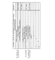
- FIG. 4 is a diagram for explaining an example of the merge block candidate list.
- FIG. 5 is a diagram illustrating the relationship between the merge block candidate size and the bit string assigned to the merge block index.
- FIG. 6 is a flowchart illustrating an example of the encoding process when the merge mode is used.
- FIG. 7 is a diagram illustrating an example of a configuration of an image encoding device that encodes an image using the merge mode.
- FIG. 8 is a flowchart illustrating an example of a decoding process when the merge mode is used.
- FIG. 9 is a diagram illustrating an example of a configuration of an image decoding apparatus that decodes an image encoded using the merge mode.
- FIG. 10 is a diagram illustrating a syntax when a merge block index is added to a bitstream.
- FIG. 11 is a block diagram showing a configuration of the image coding apparatus according to Embodiment 1.
- FIG. 11 is a block diagram showing a configuration of the image coding apparatus according to Embodiment 1.
- FIG. 12 is a flowchart showing the processing operation of the image coding apparatus according to Embodiment 1.
- FIG. 13 is a diagram showing an example of a merge block candidate list in the first embodiment.
- FIG. 14 is a flowchart showing specific processing by the bidirectional prediction prohibition size determination unit according to the first embodiment.
- FIG. 15 is a flowchart showing detailed processing of step S102 of FIG. 12 according to the first embodiment.
- FIG. 16 is a flowchart showing detailed processing of step S121 of FIG. 15 according to the first embodiment.
- FIG. 17 is a flowchart showing detailed processing of step S124 of FIG. 15 according to the first embodiment.
- FIG. 18 is a flowchart showing detailed processing of step S103 of FIG. 12 according to the first embodiment.
- FIG. 19 is a flowchart showing detailed processing of step S153 of FIG. 18 according to the first embodiment.
- FIG. 20 is a flowchart showing another detailed process of step S153 of FIG. 18 according to the first embodiment.
- FIG. 21 is a block diagram showing a configuration of the image decoding apparatus according to the second embodiment.
- FIG. 22 is a flowchart showing the processing operation of the image decoding apparatus according to the second embodiment.
- FIG. 23 is a flowchart showing detailed processing of step S203 of FIG. 22 according to the second embodiment.
- FIG. 24 is a flowchart showing detailed processing of step S205 of FIG. 22 according to the second embodiment.
- FIG. 25 is a flowchart showing detailed processing of S206 of FIG. 22 according to the second embodiment.
- FIG. 26 is a diagram illustrating an example of syntax when a merge block index is added to a bitstream according to the second embodiment.
- FIG. 27 is a diagram illustrating an example of syntax when the merge block candidate list size is fixed to the maximum number of merge block candidates according to the second embodiment.
- FIG. 28 is a block diagram illustrating a configuration of an image encoding device using the image encoding method according to the third embodiment.
- FIG. 29 is a flowchart showing the processing operation of the image coding apparatus according to Embodiment 3.
- FIG. 30 is a flowchart showing detailed processing of step S172 of FIG. 29 according to the third embodiment.
- FIG. 31 is a flowchart showing detailed processing of S182 of FIG. 30 according to the third embodiment.
- FIG. 32 is a flowchart showing another detailed process of S182 of FIG. 30 according to the third embodiment.
- FIG. 33 is a block diagram illustrating a configuration of an image decoding device according to the fourth embodiment.
- FIG. 34 is a flowchart showing a processing operation of the image decoding apparatus according to the fourth embodiment.
- FIG. 35A is a block diagram illustrating a configuration of an image encoding device which is one embodiment of the present invention.
- FIG. 35B is a flowchart illustrating processing by the image encoding device which is one embodiment of the present invention.
- FIG. 36A is a block diagram illustrating a configuration of an image decoding device which is one embodiment of the present invention.
- FIG. 36B is a flowchart illustrating processing by the image decoding device which is one embodiment of the present invention.
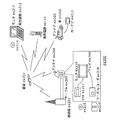
- FIG. 37 is an overall configuration diagram of a content supply system that implements a content distribution service.
- FIG. 38 is an overall configuration diagram of a digital broadcasting system.
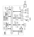
- FIG. 39 is a block diagram illustrating a configuration example of a television.
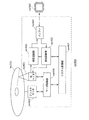
- FIG. 40 is a block diagram illustrating a configuration example of an information reproducing / recording unit that reads and writes information from and on a recording medium that is an optical disk.
- FIG. 41 is a diagram illustrating a structure example of a recording medium that is an optical disk.
- FIG. 42A is a diagram illustrating an example of a mobile phone.
- FIG. 42B is a block diagram illustrating a configuration example of a mobile phone.
- FIG. 43 is a diagram showing a structure of multiplexed data.
- FIG. 43 is a diagram showing a structure of multiplexed data.
- FIG. 44 is a diagram schematically showing how each stream is multiplexed in the multiplexed data.
- FIG. 45 is a diagram showing in more detail how the video stream is stored in the PES packet sequence.
- FIG. 46 is a diagram showing the structure of TS packets and source packets in multiplexed data.
- FIG. 47 is a diagram showing a data structure of the PMT.
- FIG. 48 shows the internal structure of the multiplexed data information.
- FIG. 49 shows the internal structure of stream attribute information.
- FIG. 50 is a diagram showing steps for identifying video data.
- FIG. 51 is a block diagram illustrating a configuration example of an integrated circuit that implements the moving picture coding method and the moving picture decoding method according to each embodiment.
- FIG. 52 is a diagram showing a configuration for switching the drive frequency.
- FIG. 52 is a diagram showing a configuration for switching the drive frequency.
- FIG. 53 is a diagram showing steps for identifying video data and switching between driving frequencies.
- FIG. 54 is a diagram showing an example of a look-up table in which video data standards are associated with drive frequencies.
- FIG. 55A is a diagram illustrating an example of a configuration for sharing a module of a signal processing unit.
- FIG. 55B is a diagram illustrating another example of a configuration for sharing a module of a signal processing unit.
- the I picture is not encoded by the inter prediction encoding process. That is, an I picture is encoded by intra-picture prediction (hereinafter referred to as “intra prediction”) encoding processing.
- the P picture is inter-predictively encoded with reference to one already encoded picture in front of or behind the current picture in display time order.
- the B picture is inter-predictively encoded with reference to two already encoded pictures that are in front of or behind the current picture in display time order.
- a reference picture list for specifying a reference picture is generated.
- the reference picture list is a list in which a reference picture index is assigned to an encoded reference picture that is referred to in inter prediction. For example, since B picture can be encoded with reference to two pictures, two reference picture lists (L0, L1) are generated.
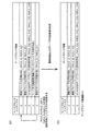
- FIG. 1A is a diagram for explaining an example of a reference picture list in a B picture.
- FIG. 1B shows an example of reference picture list 0 (L0) in prediction direction 0 in bidirectional prediction.
- the value 0 of the reference picture index 0 is assigned to the reference picture 0 in the display order 2.
- the value 1 of the reference picture index 0 is assigned to the reference picture 1 in the display order 1.
- the value 2 of the reference picture index 0 is assigned to the reference picture 2 in the display order 0. That is, a reference picture index having a smaller value is assigned to a reference picture that is closer in time to the encoding target picture in display order.
- FIG. 1C shows an example of the reference picture list 1 (L1) in the prediction direction 1 in bidirectional prediction.
- the value 0 of the reference picture index 1 is assigned to the reference picture 1 in the display order 1.
- the value 1 of the reference picture index 1 is assigned to the reference picture 0 in the display order 2.
- the value 2 of the reference picture index 2 is assigned to the reference picture 2 in display order 0.
- reference picture index values can be assigned to each reference picture for each prediction direction (reference pictures 0 and 1 in FIG. 1A), or the same reference picture index value can be assigned ( Reference picture 2 in FIG. 1A).
- a motion vector detection mode is used as an inter prediction coding mode for each coding target block in a B picture.
- the motion vector detection mode the difference value between the predicted image data and the image data of the encoding target block and the motion vector used to generate the predicted image data are encoded.
- bidirectional prediction and unidirectional prediction can be selected as the prediction direction.
- Bi-directional prediction is prediction called bi-directional prediction, bi-reference prediction, bi-prediction, or bi-prediction. In this bi-directional prediction, two pictures that have already been encoded before or after the current picture to be encoded are used. A predicted image is generated with reference to the reference image.
- bi-directional prediction is prediction involving reference to two pictures.
- bi-directional prediction is to generate a predicted image of a block to be encoded or decoded by performing motion compensation using two motion vectors.
- the unidirectional prediction is a prediction called unidirectional prediction, single reference prediction, unidirectional prediction, or unidirectional prediction.
- this unidirectional prediction one picture that has already been coded in front or rear is referred to.
- a predicted image is generated. That is, unidirectional prediction is prediction involving reference to one picture.
- unidirectional prediction is to generate a predicted image of a block to be encoded or decoded by performing motion compensation using one motion vector.
- a motion vector when a motion vector is derived in coding a B picture, a coding mode called a temporal prediction motion vector mode can be selected.
- An inter prediction encoding method in the temporal prediction motion vector mode will be described with reference to FIG.
- FIG. 2 is a diagram for explaining a motion vector in the temporal motion vector predictor mode. Specifically, FIG. 2 illustrates a case where the block a of the picture B2 is encoded in the temporal prediction motion vector mode.
- a motion vector vb used for encoding a block b (hereinafter referred to as “co-located block”) in the same position as the block a in the picture P3 which is a reference picture behind the picture B2 is It's being used.
- the motion vector vb is a motion vector used when the block b is encoded with reference to the picture P1.
- the motion vector used when coding the block a is the motion vector va1 for the picture P1 and the motion vector va2 for the picture P3.
- a merge mode is being studied as an inter prediction mode for each encoding target block in a B picture or a P picture.
- the prediction direction, the motion vector, and the reference picture index used for encoding the adjacent block of the encoding target block are copied, and the encoding target block is encoded.
- an index of an adjacent block used for copying is added to the bit stream.
- the motion direction, motion vector, and reference picture index used for encoding can be selected on the decoding side.
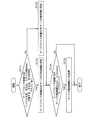
- FIG. 3 is a diagram illustrating an example of motion vectors of adjacent blocks used in the merge mode.
- an adjacent block A is an encoded block on the left side of the encoding target block.
- the adjacent block B is an encoded block that is adjacent to the encoding target block.
- the adjacent block C is an encoded block adjacent to the upper right of the encoding target block.
- the adjacent block D is an encoded block adjacent to the lower left of the encoding target block.
- the adjacent block A is a block encoded by unidirectional prediction with the prediction direction 0.
- the adjacent block A has a motion vector MvL0_A in the prediction direction 0 as a motion vector for the reference picture indicated by the reference picture index RefL0_A in the prediction direction 0.
- MvL0 indicates a motion vector that refers to a reference picture specified by reference picture list 0 (L0).
- MvL1 indicates a motion vector that refers to the reference picture specified by the reference picture list 1 (L1).
- the adjacent block B is a block encoded by unidirectional prediction in the prediction direction 1.
- the adjacent block B has a motion vector MvL1_B in the prediction direction 1 as a motion vector for the reference picture indicated by the reference picture index RefL1_B in the prediction direction 1.
- the adjacent block C is a block encoded by intra prediction.
- the adjacent block D is a block encoded by unidirectional prediction in the prediction direction 0.
- the adjacent block D has a motion vector MvL0_D in the prediction direction 0 as a motion vector for the reference picture indicated by the reference picture index RefL0_D in the prediction direction 0.
- the prediction direction of the adjacent blocks A to D, the motion vector and the reference picture index, and the prediction direction, the motion vector, and the reference picture index in the temporal prediction motion vector mode obtained using the co-located block are used. Are selected with the highest coding efficiency as the prediction direction, motion vector, and reference picture index of the current block. Then, a merge block index representing a block of the selected prediction direction, motion vector, and reference picture index is added to the bitstream.
- the encoding target block is encoded using the motion vector MvL0_A in the prediction direction 0 and the reference picture index RefL0_A. Then, only the merge block index value 0 indicating the use of the adjacent block A as shown in FIG. 4 is added to the bitstream. Thereby, the information amount of a prediction direction, a motion vector, and a reference picture index can be reduced.
- non-mergeable candidates candidates that cannot be used for encoding
- prediction directions motions Candidates whose vector and reference picture index combinations match each other
- uplicate candidates are deleted from the merge block candidates.
- the amount of code assigned to the merge block index is reduced.
- merging is impossible because the merge block candidate is (1) a block coded by intra prediction, and (2) a slice including a coding target block or a block outside a picture boundary. Or (3) a block that has not been encoded yet.
- the adjacent block C is encoded by intra prediction. Therefore, the merge block candidate of the merge block index 3 is a merge impossible candidate and is deleted from the merge block candidate list.
- the adjacent block D has the same prediction direction, motion vector, and reference picture index as the adjacent block A. Therefore, the merge block candidate with the merge block index 4 is deleted from the merge block candidate list. As a result, the number of merge block candidates is finally set to 3, and the list size of the merge block candidate list is set to 3.
- the merge block index is assigned a bit string and is variable-length coded according to the size of the merge block candidate list size.
- the bit amount assigned to the merge mode index is changed according to the size of the merge block candidate list size, thereby reducing the code amount.
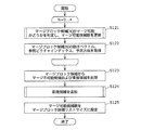
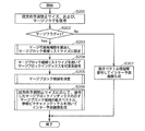
- FIG. 6 is a flowchart showing an example of the encoding process when the merge mode is used.
- step S1001 the motion vector, reference picture index, and prediction direction of the merge block candidate are acquired from the adjacent block and the co-located block.
- step S1002 duplicate candidates and non-mergeable candidates are deleted from merge block candidates.
- step S1003 the number of merge block candidates after the deletion process is set to the merge block candidate list size.
- step S1004 a merge block index to be used for encoding the current block is determined.
- the determined merge block index is variable-length encoded using the bit string determined by the merge block candidate list size.
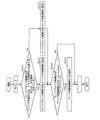
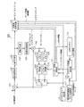
- FIG. 7 shows an example of the configuration of an image encoding apparatus 1000 that encodes an image using the merge mode.
- the image coding apparatus 1000 includes a subtraction unit 1001, an orthogonal transformation unit 1002, a quantization unit 1003, an inverse quantization unit 1004, an inverse orthogonal transformation unit 1005, an addition unit 1006, a block memory 1007, and a frame memory 1008.
- the merge block candidate calculation unit 1014 calculates merge block candidates. Then, merge block candidate calculation section 1014 transmits the calculated number of merge block candidates to variable length encoding section 1016.
- the variable length encoding unit 1016 sets the number of merge block candidates to the merge block candidate list size that is an encoding parameter. Then, the variable length coding unit 1016 assigns a bit string corresponding to the merge block candidate list size to the merge block index used for coding, and performs variable length coding on the assigned bit string.
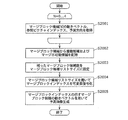
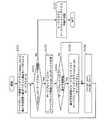
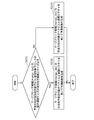
- FIG. 8 is a flowchart showing an example of the decoding process when the merge mode is used.
- step S2001 the motion vector, reference picture index, and prediction direction of the merge block candidate are acquired from the adjacent block and the co-located block.
- step S2002 duplication candidates and non-mergeable candidates are deleted from the merge block candidates.
- step S2003 the number of merge block candidates after the deletion process is set to the merge block candidate list size.
- step S2004 the merge block index used for decoding the decoding target block is decoded from the bitstream using the merge block candidate list size.
- step S2005 a prediction image is generated using a merge block candidate indicated by the decoded merge block index, and a decoding process is performed.
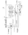
- FIG. 9 shows an example of the configuration of an image decoding apparatus 2000 that decodes an image encoded using the merge mode.
- the image decoding apparatus 2000 includes a variable length decoding unit 2001, an inverse quantization unit 2002, an inverse orthogonal transform unit 2003, an addition unit 2004, a block memory 2005, a frame memory 2006, an intra prediction unit 2007, and an inter prediction. Unit 2008, inter prediction control unit 2009, switch 2010, merge block candidate calculation unit 2011, and colPic memory 2012.
- the merge block candidate calculation unit 2011 calculates merge block candidates. Then, the merge block candidate calculation unit 2011 transmits the calculated number of merge block candidates (number of merge block candidates) to the variable length decoding unit 2001.
- the variable length decoding unit 2001 sets the number of merge block candidates to the merge block candidate list size that is a decoding parameter. Then, the variable length decoding unit 2001 decodes the merge block index included in the bitstream using the merge block candidate list size.
- FIG. 10 shows a syntax for adding a merge block index to a bitstream.
- merge_idx represents a merge block index.
- merge_flag represents a merge flag.
- NumMergeCand represents the merge block candidate list size. In this NumMergeCand, the number of merge block candidates after the merge impossible candidate and the duplicate candidate are deleted from the merge block candidates is set.
- an image is encoded or decoded using the merge mode.
- the image encoding device uses the prediction direction of the merge block candidate, the motion vector, and the reference picture index for each merge block candidate. It is necessary to generate a predicted image of the block.
- the merge block candidate is encoded by unidirectional prediction, when generating the prediction image, only the image in the region specified by one motion vector of one reference picture is stored in the frame memory. Read from.
- the merge block candidate is encoded by bi-directional prediction, when the prediction image is generated, it is specified by the motion vector corresponding to the reference picture included in each of the two reference pictures.
- bi-directional prediction is prohibited for a coding target block having a certain size or less, for example, a motion compensation size such as 8 ⁇ 4 pixels, 4 ⁇ 8 pixels, or 4 ⁇ 4 pixels. Also good.
- the prediction direction of one of the merge block candidates is used as it is as the prediction direction of the encoding target block. Therefore, in the conventional merge mode, when all merge block candidates such as adjacent blocks are encoded by bidirectional prediction, bidirectional prediction cannot be prohibited for the encoding target block. As a result, when the memory bandwidth needs to be suppressed, the merge mode cannot be selected, and the coding efficiency is lowered.
- an image encoding method includes a code including a motion vector and a reference picture index of another block that has already been encoded other than the encoding target block among a plurality of blocks included in a moving image.
- An image encoding method for merging encoding information with encoding information of the encoding target block and encoding the encoding target block, based on a spatial or temporal position of the encoding target block A candidate determining step for determining at least one block that can be used for the merge as a merge candidate, and for each merge candidate, a prediction image of the block to be encoded is encoded using the encoding information of the merge candidate.
- the motion compensation size of the encoding target block is a bi-prediction prohibition size, and any one of the merge candidates is encoded by bi-prediction in which prediction with reference to two pictures is performed.
- the encoded information for the bi-prediction of the merge candidate is used to generate a prediction image of the encoding target block.
- the motion compensation size of the encoding target block is the bi-prediction prohibition size (bidirectional prediction prohibition size) and the merge candidate (merge block candidate) is encoded by bi-prediction (bidirectional prediction).
- the encoding information for the bi-prediction of the merge candidate instead of the encoding information for the bi-prediction of the merge candidate, the encoding information for the uni-prediction (one-way prediction) is used to generate a prediction image of the encoding target block.
- the motion compensation size of the encoding target block is the minimum size, only the motion vector and the reference picture index in the prediction direction 0 (reference picture list L0) among the encoding information for the bi-prediction of the merge candidate are This is used to generate a prediction image of the encoding target block.
- the motion vector and the reference picture index in the prediction direction 1 (reference picture list L1) in the encoding information for the bi-prediction of the merge candidate are not used for generating the prediction image of the encoding target block. Therefore, the memory bandwidth can be suppressed and the encoding efficiency can be improved by the merge mode.
- a list indicating respective encoding information of the determined at least one merge candidate is created, and in the block determination step, any one of the determined at least one merge candidate is selected. If the merge candidate is a uni-prediction merge candidate, the prediction image of the encoding target block is generated and determined using the encoding information for the uni-prediction of the merge candidate shown in the list. If any one of the merge candidates is a bi-predictive merge candidate, encoding information for the bi-predictive of the merge candidate shown in the list is uni-predicted. It is also possible to convert the encoded information into one-minute encoded information, and generate the predicted image of the encoding target block using the encoded information for the one-side prediction.
- the motion vector and the reference picture index used for encoding the merge candidate can be correctly managed on the list (merge block candidate list).
- the candidate determining step if any one of the determined at least one merge candidates is a bi-predictive merge candidate, encoding information for the bi-predictive of the merge candidate is obtained.
- the list indicating the encoding information of each of the at least one merge candidate is generated so that the encoding information for the bi-prediction is not included in the list by converting the encoding information to the uni-prediction.
- a prediction image of the encoding target block may be generated for each merge candidate using the encoding information of the merge candidate shown in the list.
- the encoding information for bi-prediction of the merge candidate is the first When encoding information for one uni-prediction and encoding information for second uni-prediction, and a plurality of merge candidates among at least one merge candidate are encoded by bi-prediction, respectively.
- the encoding information used for generating the prediction image of the encoding target block among the encoding information for the bi-prediction of each of the plurality of merge candidates You may unify into the encoding information for 1st or 2nd uni-prediction.
- the encoding information for the first uni-prediction (one-way prediction for the prediction direction 0) and the encoding information for the second uni-prediction (one-way prediction for the prediction direction 1) are mixed. Therefore, the process using the encoded information can be simplified, and the encoding efficiency can be further improved.
- the motion compensation size of the encoding target block is a bi-prediction prohibited size, and any one of the merge candidates is encoded by bi-prediction.
- each size smaller than a predetermined size is comprehensively treated as a bi-prediction prohibited size, so that the motion compensation size of the encoding target block for which bi-prediction is prohibited can be widened.
- the width can be further suppressed.
- the determining step when the sum of the width and height of the encoding target block is equal to a predetermined value, it is determined that the motion compensation size of the encoding target block is the bi-prediction prohibited size. May be. For example, in the determination step, when the motion compensation size of the encoding target block is 4 ⁇ 8 pixels or 8 ⁇ 4 pixels, the motion compensation size of the encoding target block is the bi-prediction prohibited size. judge.
- the image decoding method includes encoding information including a motion vector and a reference picture index of another block that has already been decoded other than the decoding target block among a plurality of blocks included in the bitstream.
- An image decoding method for decoding the decoding target block by merging with the encoding information of the decoding target block, the extraction step extracting a merge index from the bitstream, and the spatial or temporal of the decoding target block A candidate determination step of determining at least one block that can be used for the merge as a merge candidate based on a specific position, and the extraction step extracted from the determined at least one merge candidate Block that determines the block identified by the merge index
- the motion compensation size of the decoding target block is a bi-prediction prohibition size, and two blocks determined in the block determination step are included.
- bi-prediction which is a prediction with reference to a picture of the picture
- a uni-prediction for prediction with a reference of one picture is used.
- Encoding information is used to generate a predicted image of the decoding target block.
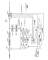
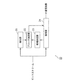
- FIG. 11 is a block diagram showing a configuration of the image coding apparatus 100 according to Embodiment 1.
- the image encoding device 100 generates a bitstream by encoding an image for each block.
- the image encoding device 100 includes a subtraction unit 101, an orthogonal transformation unit 102, a quantization unit 103, an inverse quantization unit 104, an inverse orthogonal transformation unit 105, an addition unit 106, and a block.
- a variable length encoding unit 116 and a bidirectional prediction prohibition size determination unit 117 is a variable length encoding unit 116 and a bidirectional prediction prohibition size determination unit 117.
- the subtraction unit 101 generates prediction error data by subtracting predicted image data from input image data included in the input image sequence for each block.
- the orthogonal transform unit 102 performs transform from the image domain to the frequency domain on the generated prediction error data.
- the quantization unit 103 performs a quantization process on the prediction error data converted into the frequency domain.
- the inverse quantization unit 104 performs inverse quantization processing on the prediction error data quantized by the quantization unit 103.
- the inverse orthogonal transform unit 105 performs transform from the frequency domain to the image domain on the prediction error data subjected to the inverse quantization process.
- the addition unit 106 generates reconstructed image data by adding the predicted image data and the prediction error data subjected to the inverse quantization processing by the inverse orthogonal transform unit 105 for each block.
- reconstructed image data is stored in units of blocks.
- reconstructed image data is stored in units of frames.
- the picture type determining unit 112 determines which of the I picture, B picture, and P picture is used to encode the input image data. Then, the picture type determination unit 112 generates picture type information indicating the determined picture type.
- the intra prediction unit 109 generates intra prediction image data of the block to be encoded by performing intra prediction using the reconstructed image data in units of blocks stored in the block memory 107.
- the inter prediction unit 110 performs inter prediction using the reconstructed image data in units of frames stored in the frame memory 108 and the motion vector derived by motion detection or the like, so that the inter prediction image of the encoding target block Data (predicted image) is generated.
- the switch 113 When the encoding target block is subjected to intra prediction encoding, the switch 113 outputs the intra prediction image data generated by the intra prediction unit 109 to the subtraction unit 101 and the addition unit 106 as prediction image data of the encoding target block. To do. On the other hand, when the encoding target block is subjected to inter prediction encoding, the switch 113 uses the inter prediction image data generated by the inter prediction unit 110 as the prediction image data of the encoding target block. Output to.
- the bi-prediction prohibition size determination unit 117 determines the motion compensation size of the encoding target block for which bi-prediction is prohibited by a method described later, and uses the determined size as the bi-prediction prohibition size. And output to the variable length encoding unit 116.
- the merge block candidate calculation unit 114 uses the motion vector of the adjacent block of the encoding target block and the motion vector of the co-located block stored in the colPic memory 115 (colPic information) to merge the merge mode. A block candidate is derived. Then, the merge block candidate calculation unit 114 calculates the number of mergeable candidates by a method described later.
- the merge block candidate calculation unit 114 assigns a merge block index value to the derived merge block candidate. Then, the merge block candidate calculation unit 114 transmits the merge block candidate and the merge block index to the inter prediction control unit 111. In addition, the merge block candidate calculation unit 114 transmits the calculated number of mergeable candidates to the variable length coding unit 116.
- the inter prediction control unit 111 includes a prediction mode (motion detection mode) that uses a motion vector derived by motion detection, and a prediction mode (merge mode) that uses a motion vector derived from merge block candidates according to the bidirectional prediction prohibition size. ), The prediction mode that provides the smallest prediction error is selected. Further, the inter prediction control unit 111 transmits a merge flag indicating whether or not the prediction mode is the merge mode to the variable length coding unit 116. Further, when the merge mode is selected as the prediction mode, the inter prediction control unit 111 transmits a merge block index corresponding to the determined merge block candidate to the variable length coding unit 116. Further, the inter prediction control unit 111 transfers colPic information including the motion vector of the encoding target block to the colPic memory 115.
- the variable length coding unit 116 generates a bitstream by performing variable length coding processing on the quantized prediction error data, the bidirectional prediction prohibition size, the merge flag, and the picture type information. . In addition, the variable length coding unit 116 sets the number of mergeable candidates to the merge block candidate list size. Then, the variable length coding unit 116 assigns a bit string corresponding to the merge block candidate list size to the merge block index used for coding, and performs variable length coding on the assigned bit string.
- FIG. 12 is a flowchart showing the processing operation of the image coding apparatus 100 according to the first embodiment.
- step S101 the bidirectional prediction prohibition size determination unit 117 determines a motion compensation size for prohibiting bidirectional prediction by a method described later.
- step S102 the merge block candidate calculation unit 114 derives a merge block candidate from the adjacent block and the co-located block of the encoding target block. Further, the merge block candidate calculation unit 114 calculates a merge block candidate list size by a method described later.
- the merge block candidate calculation unit 114 selects adjacent blocks A to D as merge block candidates. Further, the merge block candidate calculation unit 114 calculates a co-located merge block having a motion vector, a reference picture index, and a prediction direction calculated from the motion vector of the co-located block in the temporal prediction mode as a merge block candidate.
- the merge block candidate calculation unit 114 assigns a merge block index to each merge block candidate as shown in FIG. Then, the merge block candidate calculation unit 114 deletes non-mergeable candidates and duplicate candidates and adds a new candidate by a method to be described later, and a merge block candidate list as shown in FIG. The merge block candidate list size is calculated.
- the shorter the value of the merge block index the shorter code is assigned. That is, when the value of the merge block index is small, the amount of information necessary for the merge block index is reduced.
- the merge block candidate calculation unit 114 may, for example, measure the number of times selected as a merge block for each merge block candidate, and assign a merge block index with a small value to a block with a large number of times. Specifically, it is conceivable that the merge block selected in the adjacent block is specified, and the value of the merge block index for the specified merge block is reduced when the target block is encoded.
- merge block candidates do not have information such as motion vectors (if they are blocks encoded by intra prediction, if they are blocks located outside the boundaries of pictures and slices, etc., or have not been encoded yet) If it is a block that has not been processed), it cannot be used for encoding.
- merge block candidates that cannot be used for encoding are called non-merge candidates.
- a merge block candidate that can be used for encoding is called a mergeable candidate.
- a candidate in which any one of the other merge block candidates matches all of the motion vector, the reference picture index, and the prediction direction is referred to as an overlap candidate.
- the adjacent block C is a block encoded by intra prediction, it is determined as a non-mergeable candidate.
- the adjacent block D is a candidate for duplication because the motion vector, the reference picture index, and the prediction direction all match the adjacent block A.
- step S103 the inter prediction control unit 111 uses the prediction error of the prediction image generated using the motion vector derived by the motion detection, and the motion vector obtained from the merge block candidate according to the bidirectional prediction prohibition size.
- the prediction error of the prediction image generated in this way is compared by a method described later, and the prediction mode is selected.
- the selected prediction mode is the merge mode
- the inter prediction control unit 111 sets the merge flag to 1, and otherwise sets the merge flag to 0.
- step S104 it is determined whether or not the merge flag is 1 (that is, whether or not the prediction mode is the merge mode).
- variable length encoding unit 116 adds a merge flag to the bitstream in step S105. Further, in step S107, the variable length encoding unit 116 assigns a bit string corresponding to the merge block candidate list size as shown in FIG. 5 to the merge block index of the merge block candidate used for encoding. Then, the variable length coding unit 116 performs variable length coding on the allocated bit string.
- step S106 the variable length coding unit 116 adds the merge flag and motion detection vector mode information to the bitstream.
- step S108 the variable length coding unit 116 performs variable length coding on the bidirectional prediction prohibition size and adds it to the bitstream.
- the bidirectional prediction prohibition size is added to the SPS, PPS, slice header, etc. of the bit storm as information indicating the size.
- the bidirectional prediction prohibition size may be added in any form as long as the motion compensation size for which bidirectional prediction is prohibited is known.
- “0” is assigned as the value of the merge block index corresponding to the adjacent block A as shown in FIG.
- “1” is assigned as the value of the merge block index corresponding to the adjacent block B.
- “2” is assigned as the value of the merge block index corresponding to the co-located merge block.
- “3” is assigned as the value of the merge block index corresponding to the adjacent block C.
- “4” is assigned as the value of the merge block index corresponding to the adjacent block D.
- variable length encoding unit 116 may assign a small value to the original merge block candidate and assign a large value to the new candidate. . That is, the variable length encoding unit 116 may assign a smaller merge block index in preference to the original merge block candidate.
- the merge block candidates are not necessarily limited to the positions of the adjacent blocks A to D.
- an adjacent block located above the lower left adjacent block D may be used as a merge block candidate.
- not all adjacent blocks need to be used as merge block candidates.
- only adjacent blocks A and B may be used as merge block candidates.
- variable length coding unit 116 adds the merge block index to the bitstream in step S107 of FIG. 12, but it is not always necessary to add the merge block index to the bitstream. For example, when the merge block candidate list size is “1”, the variable length encoding unit 116 may not add the merge block index to the bitstream. Thereby, the information amount of the merge block index can be reduced.
- FIG. 14 is a flowchart showing specific processing by the bidirectional prediction prohibition size determination unit 117. This flowchart shows the specific processing of step S101 in FIG.
- the bidirectional prediction prohibition size determination unit 117 determines whether or not the memory bandwidth suppression mode is set. For example, when an image of 1920 ⁇ 1080 pixels or more is encoded, the problem of increasing the memory bandwidth becomes significant. For this reason, a memory bandwidth suppression mode is provided, and when the memory bandwidth suppression mode is on, the memory bandwidth is suppressed by prohibiting bi-directional prediction for blocks to be encoded that have a certain motion compensation size or less. To do.
- the determination in step S111 may be performed according to a profile or a level.
- the image encoding apparatus 100 performs encoding according to a profile or level that supports encoding of an image having 1920 ⁇ 1080 pixels or more, bi-directional prediction for a block to be encoded having a certain size or less is performed. May be prohibited.
- the bidirectional prediction prohibition size determination unit 117 selects, for example, 8 ⁇ 4 pixels, 4 ⁇ 8 pixels, or 4 ⁇ 4 pixels as the bidirectional prediction prohibition size in step S112. Set. Thereby, the bidirectional prediction prohibition size is determined. In general, the memory bandwidth can be greatly suppressed by prohibiting bidirectional prediction with a small motion compensation size.
- step S111 determines whether the bidirectional prediction prohibition size in step S113 is set the bidirectional prediction prohibition size in step S113.
- FIG. 15 is a flowchart showing detailed processing of step S102 of FIG. Specifically, FIG. 15 shows a method of calculating merge block candidates and a merge block candidate list size. Hereinafter, FIG. 15 will be described.
- step S121 the merge block candidate calculation unit 114 determines whether or not the merge block candidate [N] is a mergeable candidate by a method described later. Then, the merge block candidate calculation unit 114 updates the number of mergeable candidates according to the determination result.
- N is an index value for representing each merge block candidate.
- N takes a value from 0 to 4.
- the adjacent block A in FIG. 3 is allocated to the merge block candidate [0].
- the adjacent block B of FIG. 3 is allocated to the merge block candidate [1].
- a co-located merge block is allocated to the merge block candidate [2].
- the adjacent block C in FIG. 3 is allocated to the merge block candidate [3].
- the adjacent block D in FIG. 3 is allocated to the merge block candidate [4].
- step S122 the merge block candidate calculation unit 114 acquires the motion vector, reference picture index, and prediction direction of the merge block candidate [N], and adds them to the merge block candidate list.
- step S123 the merge block candidate calculation unit 114 searches the merge block candidate list for non-mergeable candidates and duplicate candidates and deletes them as shown in FIG.
- step S124 the merge block candidate calculation unit 114 adds a new candidate to the merge block candidate list by a method described later.
- the merge block candidate calculation unit 114 reassigns the value of the merge block index so that the merge block index having a smaller value is assigned in preference to the original merge block candidate. You may go.
- the merge block candidate calculation unit 114 may reassign the value of the merge block index so that a merge block index having a large value is assigned to the new candidate. Thereby, the code amount of the merge block index can be reduced.
- step S125 the merge block candidate calculation unit 114 sets the number of mergeable candidates calculated in step S121 as the merge block candidate list size.
- the number of mergeable candidates is calculated as “4” by the method described later, and “4” is set as the merge block candidate list size.
- the new candidate in step S124 is a candidate that is newly added to the merge block candidate when the number of merge block candidates has not reached the number of mergeable candidates by the method described later.
- the new candidate may be an adjacent block located above the lower left adjacent block D in FIG.
- the new candidate may be, for example, a block corresponding to the adjacent blocks A to D of the co-located block.
- the new candidate may be, for example, a block having a motion vector, a reference picture index, a prediction direction statistic value, or the like in the entire reference picture screen or a certain area.
- the merge block candidate calculation unit 114 adds a new candidate having a new motion vector, a reference picture index, and a prediction direction, Encoding efficiency can be improved.
- FIG. 16 is a flowchart showing detailed processing of step S121 of FIG. Specifically, FIG. 16 illustrates a method of determining whether the merge block candidate [N] is a mergeable candidate and updating the number of mergeable candidates. Hereinafter, FIG. 16 will be described.
- step S131 the merge block candidate calculation unit 114 determines that the merge block candidate [N] is located outside the slice or picture boundary including (1) a block encoded by intra prediction, or (2) a block to be encoded. Or (3) a block that has not been encoded yet.
- step S132 the merge block candidate calculation unit 114 sets the merge block candidate [N] as a non-mergeable candidate.
- the merge block candidate calculation unit 114 sets the merge block candidate [N] as a mergeable candidate.
- step S134 the merge block candidate calculation unit 114 determines whether the merge block candidate [N] is a mergeable candidate or a co-located merge block candidate. If the determination result in step S134 is true (Yes in S134), the merge block candidate calculation unit 114 adds 1 to the number of merge block candidates and updates the number of merge block candidates in step S135. On the other hand, if the determination result in step S134 is false (No in S134), the merge block candidate calculation unit 114 does not update the number of mergeable candidates.
- the merge block candidate calculation unit 114 sets the number of mergeable candidates to 1 regardless of whether the co-located block is a mergeable candidate or a non-mergeable candidate. Is added. Thereby, even when the information of the co-located merge block is lost due to packet loss or the like, there is no mismatch in the number of candidates that can be merged between the image encoding device and the image decoding device.
- the number of mergeable candidates is set to the merge block candidate list size in step S125 of FIG. Further, in step S107 of FIG. 12, the merge block candidate list size is used for variable length coding of the merge block index. Accordingly, even when reference picture information including a co-located block or the like is lost, the image encoding device 100 can generate a bitstream that can normally decode the merge block index.
- FIG. 17 is a flowchart showing detailed processing of step S124 of FIG. Specifically, FIG. 17 shows a method of adding a new candidate. Hereinafter, FIG. 17 will be described.
- step S141 the merge block candidate calculation unit 114 determines whether the number of merge block candidates is smaller than the number of mergeable candidates. That is, the merge block candidate calculation unit 114 determines whether or not the number of merge block candidates has reached the number of mergeable candidates.
- step S142 the merge block candidate calculation unit 114 determines whether there is a new candidate that can be added to the merge block candidate list as a merge block candidate. judge. If the determination result in step S142 is true (Yes in S142), the merge block candidate calculation unit 114 assigns a merge block index value to the new candidate and adds the new candidate to the merge block candidate list in step S143. To do. Furthermore, in step S144, the merge block candidate calculation unit 114 adds 1 to the number of merge block candidates.
- step S141 or step S142 determines whether the new candidate addition process has reached the number of candidates that can be merged, or when there is no new candidate.
- FIG. 18 is a flowchart showing detailed processing of step S103 of FIG. Specifically, FIG. 18 shows processing related to selection of merge block candidates. Hereinafter, FIG. 18 will be described.
- step S151 the inter prediction control unit 111 sets 0 to the merge block candidate index, sets the prediction error (cost) of the motion vector detection mode to the minimum prediction error, and sets 0 to the merge flag.
- the cost is calculated by, for example, the following equation of the RD optimization model.
- D coding distortion.
- R represents a generated code amount.
- the code amount necessary for encoding the motion vector used for generating the predicted image is used as R.
- ⁇ is a Lagrange's undetermined multiplier.
- step S152 the inter prediction control unit 111 determines whether the value of the merge block candidate index is smaller than the number of merge block candidates of the encoding target block. That is, the inter prediction control unit 111 determines whether there is a merge block candidate that has not yet been subjected to the processing of the following steps S153 to S155.
- step S153 the inter prediction control unit 111 sets the cost of the merge block candidate to which the merge block candidate index is allocated to the bidirectional prediction prohibition size. Accordingly, calculation is performed by a method described later.
- step S154 the inter prediction control unit 111 determines whether the calculated cost of the merge block candidate is smaller than the minimum prediction error.
- step S155 the inter prediction control unit 111 updates the values of the minimum prediction error, the merge block index, and the merge flag.
- the determination result in step S154 is false (No in S154)
- the inter prediction control unit 111 does not update the values of the minimum prediction error, the merge block index, and the merge flag.
- step S156 the inter prediction control unit 111 adds 1 to the value of the merge block candidate index, and repeats steps S152 to S156.
- step S152 determines whether there are no unprocessed merge block candidates. If the determination result in step S152 is false (No in S152), that is, if there are no unprocessed merge block candidates, in step S157, the inter prediction control unit 111 finally sets the merge flag and Determine the value of the merge block index.
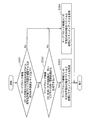
- FIG. 19 is a flowchart showing detailed processing of step S153 of FIG. Specifically, FIG. 19 shows a method for calculating a cost corresponding to a merge block candidate. Hereinafter, FIG. 19 will be described.
- step S161 the inter prediction control unit 111 determines that the prediction direction of the merge block candidate to which the merge block candidate index merge_idx is allocated is bidirectional prediction, and the motion compensation size of the encoding target block is equal to or smaller than the bidirectional prediction prohibition size. It is determined whether or not. When a merge block candidate is encoded by bidirectional prediction, it is determined that the prediction direction of the merge block candidate is bidirectional prediction.
- step S162 determines the unidirectional prediction of the merge block candidate to which the merge block candidate index merge_idx is allocated (for example, A prediction image is generated by the inter prediction unit 110 using a motion vector in the prediction direction 0) and a reference picture index, and a cost corresponding to the merge block candidate is calculated.
- the motion vector and reference picture index in the prediction direction 1 may be used in place of the motion vector and reference picture index in the prediction direction 0 as the motion vector and reference picture index for unidirectional prediction.
- step S163 the inter prediction control unit 111 refers to the motion vector for the prediction direction of the merge block candidate to which the merge block candidate index merge_idx is allocated. Using the picture index, the inter prediction unit 110 generates a prediction image, and calculates a cost corresponding to the merge block candidate.
- the inter prediction control unit 111 causes the inter prediction unit 110 to generate a prediction image using the motion vector and the reference picture index for bidirectional prediction.
- the inter prediction control unit 111 causes the inter prediction unit 110 to generate a prediction image using a motion vector and a reference picture index for unidirectional prediction. Then, the inter prediction control unit 111 calculates the cost corresponding to the generated predicted image using the above-described RD optimization model.
- the image encoding device 100 even if the prediction direction of the merge block candidate is bidirectional prediction, if the motion compensation size of the encoding target block is equal to or smaller than the bidirectional prediction prohibition size, A prediction image is generated using a motion vector and a reference picture index for one-way prediction of merge block candidates. As a result, it is possible to improve the encoding efficiency while suppressing the memory bandwidth.
- a block encoded based on a prediction image generated using a motion vector and a reference picture index for unidirectional prediction instead of bidirectional prediction is used for the next encoding target block. May be used as an adjacent block.
- the image coding apparatus 100 can further improve the coding efficiency by continuously holding the motion vector and the reference picture index for bidirectional prediction for the adjacent block.
- the image encoding apparatus 100 uses a motion vector and a reference picture for unidirectional prediction as described above, by using a motion vector and a reference picture index for unidirectional prediction instead of bidirectional prediction. Other processes that occur after that may be considered as having an index.
- the image coding apparatus 100 obtains the deblock filter strength in the deblocking process
- the block coded using the motion vector and the reference picture index for the above-described unidirectional prediction is converted into a unidirectional prediction. It is assumed to have a minute motion vector and a reference picture index.
- the image encoding device 100 calculates the filter strength based on the motion vector for one-way prediction and the reference picture index.
- the merge block candidate is one-way.
- a predicted image is generated using a motion vector for prediction and a reference picture index, the present invention is not necessarily limited thereto.
- FIG. 20 is a flowchart showing another detailed process of step S153 of FIG. Specifically, FIG. 19 shows another method for calculating the cost corresponding to the merge block candidate. Hereinafter, FIG. 20 will be described.
- step S251 the inter prediction control unit 111 determines whether the prediction direction of the merge block candidate is bidirectional prediction and the motion compensation size of the encoding target block is equal to or smaller than the bidirectional prediction prohibition size.
- step S252 the inter prediction control unit 111 indicates that the prediction image of bi-prediction using the merge block candidate is the same integer of the same picture. It is determined whether or not it can be generated from the pixel value of the position. If the determination result in step S252 is true (Yes in S252), the inter prediction control unit 111 uses the motion vector and the reference picture index for the unidirectional prediction of the merge block candidate in S253. 110 causes a predicted image to be generated.
- step S251 or step S252 uses the motion vector and the reference picture index for the prediction direction of the merge block candidate.
- the prediction unit 110 may generate a prediction image.
- the number of mergeable candidates may be calculated by always adding 1 to merge block candidates other than the co-located merge block. Accordingly, the number of mergeable candidates may be always fixed to the maximum value N of merge block candidate numbers, and a bit string may be assigned to the merge block index.
- merge block candidate list size may be fixed to the maximum number N of merge candidate block candidates
- merge block index may be encoded
- the merge block candidate list is always obtained.
- the size may be set to 5 and the merge block index may be encoded.
- the merge block candidate list size is always set to 4 and merged.
- the block index may be encoded.
- the merge block candidate list size may be determined according to the maximum number of merge block candidates.
- variable length decoding unit of the image decoding apparatus can generate a bitstream that can decode the merge block index in the bitstream without referring to information on adjacent blocks and co-located blocks.
- processing amount of the variable length decoding unit can be reduced.
- the maximum value N of the number of motion vector predictor candidates may be embedded in an SPS (Sequence Parameter Set), a PPS (Picture Parameter Set), or a slice header.
- the maximum value N of the number of motion vector predictor candidates can be switched according to the encoding target picture, and the processing amount and encoding efficiency can be improved.
- the maximum number of motion vector predictor candidates is 4 (adjacent block A, adjacent block B, adjacent block). C, adjacent block D), and in the case of a picture that refers to a co-located block, the maximum number of motion vector predictor candidates is 5 (adjacent block A, adjacent block B, co-located block, adjacent Set to block C, adjacent block D).
- SPS Sequence Parameter Set
- PPS Picture Parameter Set
- the merge mode may be forcibly selected according to the block shape used for inter prediction of the encoding target block. In that case, the amount of information may be reduced by not adding the merge flag to the bitstream.
- a skip merge mode may be used.
- the prediction direction, the motion vector, and the reference picture index are copied from the adjacent block of the encoding target block using the merge block candidate list created as shown in FIG. Then, the encoding target block is encoded.
- the skip flag is set to 1
- the skip flag and the merge block index are added to the bit stream. If the prediction error data is not 0, the skip flag is set to 0, and the skip flag, merge flag, merge block index, and prediction error data are added to the bitstream.
- a motion vector in the motion vector detection mode may be encoded using a merge block candidate list created as shown in FIG. That is, the difference is obtained by subtracting the motion vector of the merge block candidate specified by the merge block index from the motion vector in the motion vector detection mode. Then, the obtained difference and merge block index may be added to the bitstream.
- the motion vector MV_Merge of the merge block candidate is scaled using the reference picture index RefIdx_ME of the motion detection mode and the reference picture index RefIdx_Merge of the merge block candidate, and the scaled merge block candidate of the scaled motion block from the motion vector of the motion detection mode
- the difference may be obtained by subtracting the motion vector scaledMV_Merge. Then, the obtained difference and merge block index may be added to the bitstream.
- An example of the scaling equation is shown below.
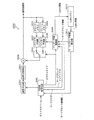
- FIG. 21 is a block diagram showing a configuration of image decoding apparatus 200 according to Embodiment 2.
- This image decoding apparatus 200 is an apparatus corresponding to the image encoding apparatus 100 according to Embodiment 1.
- the image decoding device 200 decodes, for each block, the encoded image included in the bitstream generated by the image encoding device 100 according to Embodiment 1.
- the image decoding apparatus 200 includes a variable length decoding unit 201, an inverse quantization unit 202, an inverse orthogonal transform unit 203, an addition unit 204, a block memory 205, a frame memory 206, an intra
- the prediction unit 207 includes an inter prediction unit 208, an inter prediction control unit 209, a switch 210, a merge block candidate calculation unit 211, and a colPic memory 212.
- variable length decoding unit 201 performs variable length decoding processing on the input bitstream, and generates picture type information, a merge flag, a quantization coefficient, and a bidirectional prediction prohibition size. In addition, the variable length decoding unit 201 performs variable length decoding processing of the merge block index using the number of mergeable candidates described later.
- the inverse quantization unit 202 performs an inverse quantization process on the quantization coefficient obtained by the variable length decoding process.
- the inverse orthogonal transform unit 203 generates prediction error data by transforming the orthogonal transform coefficient obtained by the inverse quantization process from the frequency domain to the image domain.
- decoded image data generated by adding the prediction error data and the prediction image data is stored in units of blocks.
- the decoded image data is stored in units of frames.
- the intra prediction unit 207 generates predicted image data of the decoding target block by performing intra prediction using the decoded image data in units of blocks stored in the block memory 205.
- the inter prediction unit 208 generates inter prediction image data (prediction image) of the decoding target block by performing inter prediction using the decoded image data in units of frames stored in the frame memory 206.
- the switch 210 When the decoding target block is intra prediction decoded, the switch 210 outputs the intra prediction image data generated by the intra prediction unit 207 to the adding unit 204 as prediction image data of the decoding target block. On the other hand, when the decoding target block is subjected to inter prediction decoding, the switch 210 outputs the inter prediction image data generated by the inter prediction unit 208 to the adding unit 204 as prediction image data of the decoding target block.
- the merge block candidate calculation unit 211 uses the motion vector of the adjacent block of the decoding target block and the motion vector of the co-located block stored in the colPic memory 212 (colPic information) to merge the merge mode merge block Candidates are derived by the method described below. In addition, the merge block candidate calculation unit 211 assigns a merge block index value to each derived merge block candidate. Then, the merge block candidate calculation unit 211 transmits the merge block candidate and the merge block index to the inter prediction control unit 209.
- the inter prediction control unit 209 causes the inter prediction unit 208 to generate an inter prediction image using the information of the motion vector detection mode.
- the merge flag is “1”
- the inter prediction control unit 209 determines a motion vector, a reference picture index, and a prediction direction to be used for inter prediction based on the decoded merge block index from a plurality of merge block candidates. To do. Then, the inter prediction control unit 209 uses the determined motion vector, reference picture index, and prediction direction to cause the inter prediction unit 208 to generate an inter prediction image by a method described later according to the bidirectional prediction prohibition size.
- the inter prediction control unit 209 transfers colPic information including the motion vector of the decoding target block to the colPic memory 212.
- the addition unit 204 generates decoded image data by adding the predicted image data and the prediction error data.
- FIG. 22 is a flowchart showing the processing operation of the image decoding apparatus 200 according to the second embodiment.
- step S201 the variable length decoding unit 201 decodes the bidirectional prediction prohibition size and the merge flag.
- step S202 if the merge flag is “1” (Yes in S202), in step S203, the merge block candidate calculation unit 211 calculates the number of mergeable candidates by a method described later. Then, the merge block candidate calculation unit 211 sets the calculated number of mergeable candidates as the merge block candidate list size.
- step S204 the variable length decoding unit 201 performs variable length decoding on the merge block index in the bitstream using the merge block candidate list size.
- step S205 the merge block candidate calculation unit 211 generates a merge block candidate from the adjacent block and the co-located block of the decoding target block by a method described later.
- step S206 the inter prediction control unit 209 uses the decoded bidirectional prediction prohibition size, the motion vector of the merge block candidate indicated by the merge block index, the reference picture index, and the prediction direction in a method to be described later.
- the inter prediction image is generated by the inter prediction unit 208.
- step S207 the inter prediction unit 208 uses the motion vector detection mode information decoded by the variable length decoding unit 201 to perform inter prediction images. Is generated.
- the merge block index may be estimated as “0” without being decoded.
- FIG. 23 is a flowchart showing detailed processing of step S203 of FIG. Specifically, FIG. 23 illustrates a method of determining whether or not the merge block candidate [N] is a mergeable candidate and calculating the number of mergeable candidates. Hereinafter, FIG. 23 will be described.
- step S211 the merge block candidate calculation unit 211 determines that the merge block candidate [N] is (1) a block decoded by intra prediction, or (2) a block that is located outside a slice or picture boundary including a decoding target block. Or (3) Determine whether the block has not been decoded yet.
- step S211 If the determination result in step S211 is true (Yes in S211), the merge block candidate calculation unit 211 sets the merge block candidate [N] as a non-mergeable candidate in step S212. On the other hand, if the determination result in step S211 is false (No in S211), in step S213, the merge block candidate calculation unit 211 sets the merge block candidate [N] as a mergeable candidate.
- step S214 the merge block candidate calculation unit 211 determines whether the merge block candidate [N] is a mergeable candidate or a co-located merge block candidate. If the determination result in step S214 is true (Yes in S214), the merge block candidate calculation unit 211 adds 1 to the number of merge block candidates and updates the number of merge block candidates in step S215. On the other hand, if step S214 is false (No in S214), the merge block candidate calculation unit 211 does not update the number of mergeable candidates.
- the merge block candidate calculation unit 211 sets the number of mergeable candidates to 1 regardless of whether the co-located block is a mergeable candidate or a non-mergeable candidate. Is added. Thereby, even when the information of the co-located merge block is lost due to packet loss or the like, there is no mismatch in the number of candidates that can be merged between the image encoding device and the image decoding device.
- the number of mergeable candidates is set to the merge block candidate list size in step S203 of FIG. Further, in step S204 of FIG. 22, the merge block candidate list size is used for variable length decoding of the merge block index. Accordingly, even when reference picture information including a co-located block or the like is lost, the image decoding apparatus 200 can normally decode the merge block index.
- FIG. 24 is a flowchart showing detailed processing of step S205 of FIG. Specifically, FIG. 24 shows a method of calculating merge block candidates. Hereinafter, FIG. 24 will be described.
- step S221 the merge block candidate calculation unit 211 acquires the motion vector, reference picture index, and prediction direction of the merge block candidate [N], and adds them to the merge block candidate list.
- step S222 the merge block candidate calculation unit 211 searches the merge block candidate list for non-mergeable candidates and duplicate candidates and deletes them as shown in FIG.
- step S223 the merge block candidate calculation unit 211 adds a new candidate to the merge block candidate list by the same method as in FIG.
- FIG. 25 is a flowchart showing detailed processing of S206 of FIG. Specifically, FIG. 25 illustrates a method for generating a prediction image according to the bidirectional prediction prohibition size. Hereinafter, FIG. 25 will be described.
- step S231 the inter prediction control unit 209 determines whether the prediction direction of the merge block candidate to which the merge block candidate index merge_idx is assigned is bidirectional prediction, and the motion compensation size of the decoding target block is equal to or smaller than the bidirectional prediction prohibition size. Determine whether or not.
- step S232 the inter prediction control unit 209 determines the one-way prediction of merge block candidates to which the merge block candidate index merge_idx is allocated (for example, The inter prediction unit 208 is caused to generate a prediction image using the motion vector and the reference picture index in the prediction direction 0).
- a motion vector in the prediction direction 1 and a reference picture index may be used instead of the motion vector in the prediction direction 0 and the reference picture index as the motion vector and the reference picture index for unidirectional prediction.
- step S233 the inter prediction control unit 209 refers to the motion vector for the prediction direction of the merge block candidate to which the merge block candidate index merge_idx is allocated.
- the inter prediction unit 208 is caused to generate a prediction image using the picture index. That is, if the prediction direction of the merge block candidate is bidirectional prediction, the inter prediction control unit 209 causes the inter prediction unit 208 to generate a prediction image using bidirectional prediction.
- the inter prediction control unit 209 uses the unidirectional prediction to predict a prediction image. Is generated by the inter prediction unit 110.
- FIG. 26 is a diagram illustrating an example of syntax when a merge block index is added to a bitstream.
- merge_idx represents a merge block index
- merge_flag represents a merge flag.
- NumMergeCand represents the merge block candidate list size, and in this embodiment, the number of mergeable candidates calculated in the processing flow of FIG. 23 is set.
- the unidirectional prediction of the merge block candidate is performed.
- a predicted image is generated using the motion vector of minutes and the reference picture index.
- a block decoded based on a prediction image generated using a motion vector and a reference picture index for unidirectional prediction instead of bidirectional prediction is adjacent to the next decoding target block.
- the image decoding apparatus 200 can appropriately decode a bitstream with improved encoding efficiency by continuously holding the motion vector and the reference picture index for bidirectional prediction for the adjacent block. It becomes possible.
- the image decoding apparatus 200 has a block decoded using a motion vector and a reference picture index for unidirectional prediction instead of bidirectional prediction as described above, and has a motion vector and a reference picture index for unidirectional prediction. Other processing that occurs thereafter may be performed.
- the image decoding apparatus 200 obtains the filter strength of the deblock in the deblocking process, the block decoded using the motion vector and the reference picture index for the unidirectional prediction described above is used.
- the image decoding apparatus 200 calculates the filter strength based on the motion vector for unidirectional prediction and the reference picture index.
- the prediction direction of the merge block candidate is bidirectional prediction and the motion compensation size of the decoding target block is equal to or smaller than the bidirectional prediction prohibition size, the one-way prediction of the merge block candidate is performed.
- the predicted image is generated using the motion vector of minutes and the reference picture index, the present invention is not necessarily limited thereto.
- the inter prediction control unit 209 determines that the prediction direction of the merge block candidate is bidirectional prediction and the motion compensation size of the decoding target block is equal to or smaller than the bidirectional prediction prohibition size. If there is, it may be determined whether a prediction image of bidirectional prediction using the merge block candidate cannot be generated from pixel values at the same integer position of the same picture. If the determination result is true, the inter prediction control unit 209 causes the inter prediction unit 208 to generate a prediction image using the motion vector and the reference picture index for the unidirectional prediction of the merge block candidate. On the other hand, if the determination result is false, the inter prediction control unit 209 may cause the inter prediction unit 208 to generate a prediction image using the motion vector and the reference picture index for the prediction direction of the merge block candidate.
- the number of mergeable candidates may be calculated by always adding 1 to merge block candidates other than the co-located merge block. Accordingly, the number of mergeable candidates may be always fixed to the maximum value N of merge block candidate numbers, and a bit string may be assigned to the merge block index.
- merge block candidate list size may be fixed to the maximum number N of merge block candidates, and the merge block index may be decoded.
- the merge block candidate list is always obtained.
- the size may be set to 5 and the merge block index may be decoded.
- variable length decoding unit 201 can decode the merge block index in the bitstream without referring to the information of the adjacent block and the co-located block.
- the processing amount of the variable length decoding unit 201 can be reduced by omitting the processing of steps S214 and S215 in FIG.
- FIG. 27 is a diagram illustrating an example of syntax when the merge block candidate list size is fixed to the maximum number of merge block candidates.
- the image decoding apparatus 200 may identify the maximum number N of motion vector predictor candidates using a value embedded in an SPS (Sequence Parameter Set), PPS (Picture Parameter Set), or a slice header. Good.
- the maximum number of motion vector predictor candidates is 4 (adjacent block A, adjacent block B, adjacent block) C, adjacent block D).
- the maximum number of motion vector predictor candidates is 5 (adjacent block A, adjacent block B, co-located block, adjacent block C, adjacent block D).
- the maximum value N of the number of motion vector predictor candidates is set to SPS (Sequence Parameter Set), PPS (Picture Parameter Set), or slice. It decodes from a header etc. and decodes a prediction motion vector index using the value.
- FIG. 28 is a block diagram showing a configuration of an image coding apparatus 300 using the image coding method according to Embodiment 3.
- the third embodiment is different from the first embodiment only in that a merge block candidate is calculated according to the bidirectional prediction prohibition size (a merge block candidate list is created according to the bidirectional prediction prohibition size). Since the other points are the same, detailed description is omitted.
- the image encoding device 300 includes a subtraction unit 101, an orthogonal transformation unit 102, a quantization unit 103, an inverse quantization unit 104, an inverse orthogonal transformation unit 105, an addition unit 106, and a block.
- a variable length encoding unit 116 and a bidirectional prediction prohibition size determination unit 117 is a variable length encoding unit 116 and a bidirectional prediction prohibition size determination unit 117.
- the bidirectional prediction prohibition size determination unit 117 determines the size of motion compensation for prohibiting bidirectional prediction in the same manner as in FIG. 14, and determines the determined bidirectional prediction prohibition size as the merge block candidate calculation unit 114 and the variable length.
- the data is output to the encoding unit 116.
- the merge block candidate calculation unit 114 uses the colPic information such as the motion vector of the adjacent block of the encoding target block and the co-located block stored in the colPic memory to be described later according to the bidirectional prediction prohibition size. The method derives merge block candidates in merge mode. Further, the merge block candidate calculation unit 114 calculates the number of mergeable candidates by the same method as in FIG. In addition, the merge block candidate calculation unit 114 assigns a merge block index value to the derived merge block candidate. Then, the merge block candidate calculation unit 114 sends the merge block candidate and the merge block index to the inter prediction control unit 111. In addition, the merge block candidate calculation unit 114 transmits the calculated number of mergeable candidates to the variable length coding unit 116.
- the inter prediction control unit 111 has the prediction with the smallest prediction error among the inter prediction image generated using the motion vector derived by motion detection and the inter prediction image generated using the motion vector derived by the merge mode. Inter prediction coding is performed using an image (prediction mode). Further, the inter prediction control unit 111 sends a merge flag indicating whether or not the prediction mode is the merge mode to the variable length coding unit 116. Furthermore, when the merge mode is selected as the prediction mode, the inter prediction control unit 111 sends a merge block index corresponding to the determined merge block candidate to the variable length coding unit 116. Further, the inter prediction control unit 111 transfers colPic information including the motion vector of the encoding target block to the colPic memory 115.
- FIG. 29 is a flowchart showing the processing operation of the image coding apparatus 300 according to the third embodiment.
- step S171 the bidirectional prediction prohibition size determination unit 117 determines a motion compensation size for prohibiting bidirectional prediction by the same method as in step S101 of FIG.
- step S172 the merge block candidate calculation unit 114 derives merge block candidates from the adjacent block and the co-located block of the encoding target block by a method described later according to the bidirectional prediction prohibition size. Further, the merge block candidate calculation unit 114 calculates the merge block candidate list size.
- the merge block candidate calculation unit 114 selects adjacent blocks A to D as merge block candidates. Further, the merge block candidate calculation unit 114 calculates a co-located merge block having a motion vector, a reference picture index, and a prediction direction calculated from the motion vector of the co-located block in the temporal prediction mode as a merge block candidate.
- the merge block candidate calculation unit 114 assigns a merge block index to each merge block candidate as shown in FIG. Then, the merge block candidate calculation unit 114 deletes the merge impossible candidate and the duplicate candidate, and adds a new candidate, so that the merge block candidate list and the merge block candidate list size as shown in FIG. Is calculated.
- the shorter the value of the merge block index the shorter code is assigned. That is, when the value of the merge block index is small, the amount of information necessary for the merge block index is reduced.
- the merge block candidate calculation unit 114 may, for example, measure the number of times selected as a merge block for each merge block candidate, and assign a merge block index with a small value to a block with a large number of times. Specifically, it is conceivable that the merge block selected in the adjacent block is specified, and the value of the merge block index for the specified merge block is reduced when the target block is encoded.
- merge block candidates do not have information such as motion vectors (if they are blocks encoded by intra prediction, if they are blocks located outside the boundaries of pictures and slices, etc., or have not been encoded yet) If it is a block that has not been processed), it cannot be used for encoding.
- merge block candidates that cannot be used for encoding are called non-merge candidates.
- a merge block candidate that can be used for encoding is called a mergeable candidate.
- a candidate in which any one of the other merge block candidates matches all of the motion vector, the reference picture index, and the prediction direction is referred to as an overlap candidate.
- the adjacent block C is a block encoded by intra prediction, it is determined as a non-mergeable candidate.
- the adjacent block D is a candidate for duplication because the motion vector, the reference picture index, and the prediction direction all match the adjacent block A.
- step S173 the inter prediction control unit 111 predicts the prediction error of the prediction image generated using the motion vector derived by the motion detection and the prediction error of the prediction image generated using the motion vector obtained from the merge block candidate. And the prediction mode is selected. Here, if the selected prediction mode is the merge mode, the inter prediction control unit 111 sets the merge flag to 1, and otherwise sets the merge flag to 0.
- step S174 it is determined whether or not the merge flag is 1 (that is, whether or not the prediction mode is the merge mode).
- step S175 the variable length encoding unit 116 adds a merge flag to the bitstream. Further, in step S177, the variable length coding unit 116 assigns a bit string corresponding to the merge block candidate list size as shown in FIG. 5 to the merge block index of the merge block candidate used for coding. Then, the variable length coding unit 116 performs variable length coding on the allocated bit string.
- step S176 the variable length coding unit 116 adds the merge flag and motion detection vector mode information to the bitstream.
- step S178 the variable length encoding unit 116 performs variable length encoding on the bidirectional prediction prohibition size and adds it to the bitstream.
- the bidirectional prediction prohibition size is added to the SPS, PPS, slice header, etc. of the bit storm as information indicating the size.
- the bidirectional prediction prohibition size may be added in any form as long as the motion compensation size for which bidirectional prediction is prohibited is known.
- “0” is assigned as the value of the merge block index corresponding to the adjacent block A as shown in FIG.
- “1” is assigned as the value of the merge block index corresponding to the adjacent block B.
- “2” is assigned as the value of the merge block index corresponding to the co-located merge block.
- “3” is assigned as the value of the merge block index corresponding to the adjacent block C.
- “4” is assigned as the value of the merge block index corresponding to the adjacent block D.
- variable length encoding unit 116 may assign a small value to the original merge block candidate and assign a large value to the new candidate. That is, the variable length encoding unit 116 may assign a smaller merge block index in preference to the original merge block candidate.
- the merge block candidates are not necessarily limited to the positions of the adjacent blocks A to D.
- an adjacent block located above the lower left adjacent block D may be used as a merge block candidate.
- not all adjacent blocks need to be used as merge block candidates.
- only adjacent blocks A and B may be used as merge block candidates.
- variable length coding unit 116 adds the merge block index to the bitstream in step S177 of FIG. 29, but it is not always necessary to add the merge block index to the bitstream. For example, when the merge block candidate list size is “1”, the variable length encoding unit 116 may not add the merge block index to the bitstream. Thereby, the information amount of the merge block index can be reduced.
- FIG. 30 is a flowchart showing detailed processing of step S172 of FIG. Specifically, FIG. 30 shows a method of calculating merge block candidates and merge block candidate list sizes. Hereinafter, FIG. 30 will be described.
- step S181 the merge block candidate calculation unit 114 determines whether the merge block candidate [N] is a mergeable candidate. Then, the merge block candidate calculation unit 114 updates the number of mergeable candidates according to the determination result.
- N is an index value for representing each merge block candidate.
- N takes a value from 0 to 4.
- the adjacent block A in FIG. 3 is allocated to the merge block candidate [0].
- the adjacent block B of FIG. 3 is allocated to the merge block candidate [1].
- a co-located merge block is allocated to the merge block candidate [2].
- the adjacent block C in FIG. 3 is allocated to the merge block candidate [3].
- the adjacent block D in FIG. 3 is allocated to the merge block candidate [4].
- step S182 the merge block candidate calculation unit 114 acquires a motion vector, a reference picture index, and a prediction direction of the merge block candidate [N] by a method described later according to the bidirectional prediction prohibition size, and merge block candidate Add to list.
- step S183 as shown in FIG. 13, the merge block candidate calculation unit 114 searches the merge block candidate list for non-mergeable candidates and duplicate candidates and deletes them.
- step S184 the merge block candidate calculation unit 114 adds a new candidate to the merge block candidate list.
- the merge block candidate calculation unit 114 reassigns the value of the merge block index so that the merge block index having a smaller value is assigned in preference to the original merge block candidate. You may go.
- the merge block candidate calculation unit 114 may reassign the value of the merge block index so that a merge block index having a large value is assigned to the new candidate. Thereby, the code amount of the merge block index can be reduced.
- step S185 the merge block candidate calculation unit 114 sets the number of mergeable candidates calculated in step S181 as the merge block candidate list size.
- the number of mergeable candidates is calculated as “4”, and “4” is set as the merge block candidate list size.
- the new candidate in step S184 is a candidate that is newly added to the merge block candidate when the number of merge block candidates has not reached the number of mergeable candidates.
- the new candidate may be an adjacent block located above the lower left adjacent block D in FIG.
- the new candidate may be, for example, a block corresponding to the adjacent blocks A to D of the co-located block.
- the new candidate may be, for example, a block having a motion vector, a reference picture index, a prediction direction statistic value, or the like in the entire reference picture screen or a certain area.
- the merge block candidate calculation unit 114 adds a new candidate having a new motion vector, a reference picture index, and a prediction direction, Encoding efficiency can be improved.
- FIG. 31 is a flowchart showing detailed processing of S182 of FIG. Specifically, FIG. 31 illustrates a method of acquiring the motion vector, reference picture index, and prediction direction of the merge block candidate [N] according to the bidirectional prediction prohibition size. Hereinafter, FIG. 31 will be described.
- step S191 the merge block candidate calculation unit 114 determines whether the prediction direction of the merge block candidate [N] is bidirectional prediction and the motion compensation size of the encoding target block is equal to or smaller than the bidirectional prediction prohibition size.
- step S192 the merge block candidate calculation unit 114 determines the motion vector and reference picture index (for example, prediction) for the unidirectional prediction of the merge block candidate [N]. (Direction 0 motion vector and reference picture index) are obtained and added to the merge block candidate list. Note that the merge block candidate calculation unit 114 uses the motion vector and reference picture index in the prediction direction 1 instead of the motion vector and reference picture index in the prediction direction 0 as the motion vector and reference picture index for unidirectional prediction. It doesn't matter.
- any method such as calculating an average vector from the motion vectors in the prediction direction 0 and the prediction direction 1 and the reference picture index, and generating a motion vector and a reference picture index for unidirectional prediction, for example. May be used to generate a motion vector and reference picture index for unidirectional prediction from a motion vector and reference picture index for bidirectional prediction.
- step S193 the merge block candidate calculation unit 114 acquires a motion vector and a reference picture index for the prediction direction of the merge block candidate [N], and Add to merge block candidate list. That is, if the prediction direction of the merge block candidate is bidirectional prediction, the merge block candidate calculation unit 114 adds the motion vector and the reference picture index for bidirectional prediction to the merge block candidate list, and predicts the merge block candidate. If is one-way prediction, a motion vector and a reference picture index for one-way prediction are added to the merge block candidate list.
- the image coding apparatus 300 even if the prediction direction of the merge block candidate is bidirectional prediction, if the motion compensation size of the encoding target block is equal to or smaller than the bidirectional prediction prohibited size, A merge block candidate list is generated using a motion vector and a reference picture index for one-way prediction of merge block candidates. As a result, a merge block candidate to be used for encoding the block to be encoded is selected from a merge block candidate list in which all merge block candidates are unidirectional prediction, so that encoding efficiency is improved while suppressing memory bandwidth. It becomes possible to improve.
- the prediction direction, the motion vector, and the reference picture index are acquired from the merge block candidate [N] according to the bidirectional prediction prohibition size.
- the merge block candidate calculation unit 114 determines whether the motion compensation size of the encoding target block is equal to or smaller than the bidirectional prediction prohibition size, If true, out of the merge block candidates included in the merge block candidate list, the motion vector and reference picture index for bidirectional prediction may be converted into the motion vector and reference picture index for unidirectional prediction.
- bidirectional prediction may be converted into unidirectional prediction in prediction direction 0, and invalid values may be set in the motion vector and reference picture index in prediction direction 1.
- bidirectional prediction may be converted into unidirectional prediction in prediction direction 1, and invalid values may be set in the motion vector and reference picture index in prediction direction 0.
- the merge block candidate is one-way.
- the motion vector and the reference picture index for prediction are acquired and added to the merge block candidate list, this is not necessarily limited thereto.
- FIG. 32 is a flowchart showing another detailed process of S182 of FIG. Specifically, FIG. 32 illustrates another method of obtaining the motion vector, reference picture index, and prediction direction of the merge block candidate [N] according to the bidirectional prediction prohibition size.
- step S261 the merge block candidate calculation unit 114 determines that the prediction direction of the merge block candidate [N] is bidirectional prediction, and the motion compensation size of the encoding target block is bidirectional prediction prohibited. Determine if it is below the size.
- step S262 the merge block candidate calculation unit 114 further determines that the prediction image of bidirectional prediction using the merge block candidate is the same in the same picture. It is determined whether or not the pixel value at the integer position cannot be generated.
- step S263 the merge block candidate calculation unit 114 acquires a motion vector and a reference picture index for the unidirectional prediction of the merge block candidate. Add to merge block candidate list.
- step S261 or step S262 determines whether the prediction result in step S261 or step S262 is false (No in S261 or S262), the merge block candidate calculation unit 114 acquires the motion vector and reference picture index for the prediction direction of the merge block candidate, and merges them. Add to the block candidate list.
- FIG. 33 is a block diagram illustrating a configuration of an image decoding apparatus 400 using an image decoding method corresponding to the third embodiment.
- the fourth embodiment is different from the second embodiment only in that a merge block candidate is calculated according to the bidirectional prediction prohibition size (a merge block candidate list is created according to the bidirectional prediction prohibition size). Since the other points are the same, detailed description is omitted.
- the image decoding apparatus 400 includes a variable length decoding unit 201, an inverse quantization unit 202, an inverse orthogonal transform unit 203, an addition unit 204, a block memory 205, a frame memory 206, an intra
- the prediction unit 207 includes an inter prediction unit 208, an inter prediction control unit 209, a switch 210, a merge block candidate calculation unit 211, and a colPic memory 212.
- the variable length decoding unit 201 performs variable length decoding processing on the input bitstream, and generates picture type information, a merge flag, a quantization coefficient, and a bidirectional prediction prohibition size. Further, the variable length decoding unit 201 calculates the number of mergeable candidates by the same method as in FIG. 23 and performs variable length decoding processing of the merge block index.
- the merge block candidate calculation unit 211 uses the motion vector of the adjacent block of the decoding target block, the motion vector of the co-located block stored in the colPic memory 212 (colPic information), and the like. Accordingly, merge mode merge block candidates are derived by a method described later.
- the merge block candidate calculation unit 211 also assigns a merge block index value to each derived merge block candidate, and sends the merge block candidate and the merge block index to the inter prediction control unit 209.
- the inter prediction control unit 209 causes the inter prediction unit 208 to generate an inter prediction image using the information of the motion vector detection mode.
- the merge flag is “1”
- the inter prediction control unit 209 determines a motion vector, a reference picture index, and a prediction direction to be used for inter prediction based on the decoded merge block index from a plurality of merge block candidates. To do.
- the inter prediction control unit 209 causes the inter prediction unit 208 to generate an inter prediction image using the determined motion vector, reference picture index, and prediction direction.
- the inter prediction control unit 209 transfers colPic information including the motion vector of the decoding target block to the colPic memory 212.
- the addition unit 204 generates decoded image data by adding the predicted image data and the prediction error data.
- FIG. 34 is a flowchart showing the processing operation of the image decoding apparatus 400 according to the fourth embodiment.
- step S241 the variable length decoding unit 201 decodes the bidirectional prediction prohibition size and the merge flag.
- step S243 the merge block candidate calculation unit 211 calculates the number of mergeable candidates in the same manner as in FIG. Then, the merge block candidate calculation unit 211 sets the calculated number of mergeable candidates as the merge block candidate list size.
- step S244 the variable length decoding unit 201 performs variable length decoding on the merge block index in the bitstream using the merge block candidate list size.
- step S245 the merge block candidate calculation unit 211 generates a merge block candidate from the adjacent block of the decoding target block and the co-located block by the same method as in FIG. 30 according to the bidirectional prediction prohibition size.
- step S246 the inter prediction control unit 209 causes the inter prediction unit 208 to generate an inter prediction image using the motion vector, reference picture index, and prediction direction of the merge block candidate indicated by the decoded merge block index.
- step S242 if the merge flag is “0” (No in S242), in step S247, the inter prediction unit 208 uses the motion vector detection mode information decoded by the variable length decoding unit 201 to generate an inter prediction image. Is generated.
- the merge block index may be estimated as “0” without being decoded.
- the unidirectional prediction of the merge block candidate is performed.
- a merge block candidate list is generated using the minute motion vector and the reference picture index.
- the merge block candidate used for decoding the decoding target block is selected from the merge block candidate list in which all merge block candidates are unidirectional prediction, and thus the encoding efficiency is improved while suppressing the memory bandwidth. It becomes possible to properly decode the bitstream.
- the prediction direction, the motion vector, and the reference picture index are acquired from the merge block candidate [N] according to the bidirectional prediction prohibition size.
- the merge block candidate calculation unit 211 determines whether or not the motion compensation size of the decoding target block is equal to or smaller than the bidirectional prediction prohibition size after the merge block candidate list is created. Determine. If the determination result is true, the merge block candidate calculation unit 211 uses the motion vector and reference picture index for bidirectional prediction as the motion vector for unidirectional prediction among the merge block candidates included in the merge block candidate list. Convert to reference picture index.
- the merge block candidate calculation unit 211 may convert bidirectional prediction into unidirectional prediction in the prediction direction 0 and set invalid values for the motion vector and the reference picture index in the prediction direction 1.
- the merge block candidate calculation unit 211 may convert the bidirectional prediction into a unidirectional prediction in the prediction direction 1 and set invalid values for the motion vector and the reference picture index in the prediction direction 0.
- the merge block Although motion vectors and reference picture indexes for candidate unidirectional prediction are acquired and added to the merge block candidate list, the present invention is not necessarily limited thereto.
- merge block candidate calculation is performed when the prediction direction of the merge block candidate is bidirectional prediction and the motion compensation size of the decoding target block is equal to or smaller than the bidirectional prediction prohibition size.
- the unit 211 determines whether or not a prediction image for bidirectional prediction using the merge block candidate cannot be generated from pixel values at the same integer position of the same picture.
- the merge block candidate calculation unit 211 acquires a motion vector and a reference picture index for the unidirectional prediction of the merge block candidate and adds them to the merge block candidate list.
- the merge block candidate calculation unit 211 may acquire a motion vector and a reference picture index for the prediction direction of the merge block candidate and add them to the merge block candidate list. Absent. In general, when a prediction image in each prediction direction of bidirectional prediction can be generated from a pixel value at the same integer position of the same picture by a motion compensation filter, a reference picture for unidirectional prediction may be read from the memory. Therefore, in such a case, it is possible to appropriately decode a bit stream with improved encoding efficiency while suppressing memory bandwidth without necessarily prohibiting bidirectional prediction.
- the image encoding device and the image decoding device have been described based on Embodiments 1 to 4.
- the present invention is not limited to this embodiment. Absent. Unless it deviates from the gist of the present invention, one or more of the present invention may be applied to the present embodiment in which various modifications conceived by those skilled in the art have been made in this embodiment, or a combination of components in different embodiments. It may be included within the scope of the embodiments.
- FIG. 35A is a block diagram illustrating a configuration of an image encoding device which is one embodiment of the present invention.
- This image encoding device 10 converts encoding information including other block motion vectors that have already been encoded other than the encoding target block and a reference picture index from among a plurality of blocks included in the moving image.
- the candidate determination unit 11 corresponds to the merge block candidate calculation unit 114 of the first or third embodiment
- the block determination unit 12 includes the inter prediction unit 110 and the inter prediction control unit of the first or third embodiment. It corresponds to 111.
- the encoding unit 13 corresponds to the inter prediction unit 110, the subtraction unit 101, and the like of the first or third embodiment.
- the adding unit 14 corresponds to the variable length coding unit 116 of the first or third embodiment.
- FIG. 35B is a flowchart showing processing by the image encoding device 10.
- the candidate determination unit 11 determines at least one block that can be used for merging as a merge candidate based on the spatial or temporal position of the encoding target block (S11).
- the block determination unit 12 For each merge candidate, the block determination unit 12 generates a prediction image of the encoding target block using the encoding information of the merge candidate, and compares each cost of the prediction image with each other, thereby at least 1 A block used for encoding the encoding target block is determined from the two merge candidates (S12).
- the encoding unit 13 generates a bit stream including the encoded block by encoding the encoding target block using the encoding information of the block determined by the block determination unit 12 (S13). ).
- the addition unit 14 adds a merge index for specifying the block determined by the block determination unit 12 to the bitstream (S14).
- the block determination unit 12 determines that the motion compensation size of the encoding target block is a bi-prediction prohibited size, and that any one of the merge candidates is at least two pictures.
- a code for uni-prediction which is prediction with reference to one picture
- encoding information for bi-prediction of the merge candidate Information is used to generate a predicted image of the encoding target block.
- merge candidate, bi-prediction prohibition size, and merge index are the merge block candidate, bi-prediction prohibition size, and merge block index of the first to fourth embodiments.
- the motion compensation size of the encoding target block is the bi-prediction prohibited size and the merge candidate is encoded by bi-prediction, instead of the encoding information for the bi-prediction of the merge candidate.
- the encoded information for uni-prediction is used to generate a predicted image of the encoding target block. For example, when the motion compensation size of the encoding target block is the minimum size, only the motion vector in the prediction direction 0 and the reference picture index among the encoding information for the bi-prediction of the merge candidate are predicted for the encoding target block. Used for image generation.
- the motion vector in the prediction direction 1 and the reference picture index among the encoding information for the bi-prediction of the merge candidate are not used for generating the prediction image of the encoding target block. Therefore, the memory bandwidth can be suppressed and the encoding efficiency can be improved by the merge mode.
- the bidirectional prediction prohibition size is determined.
- the bidirectional prediction prohibition size may be set to a constant size that is common to the image decoding apparatus without determining the bidirectional prediction prohibition size.
- two-way prediction prohibition size determination part 117 of Embodiment 1 and 3 can be omitted, and the structure of the image coding apparatuses 100 and 300 can be simplified.
- step S12 the block determination unit 12 described above uses encoding information for uni-prediction instead of encoding information for bi-prediction of merge candidates for generation of a prediction image of an encoding target block.
- the encoded information for uni-prediction may be generated at any timing as long as the prediction image is not generated.
- the encoding information for bidirectional prediction shown in the merge block candidate list is converted into the encoding information for unidirectional prediction. Also good.
- a list (merge block candidate list) indicating the encoding information of each of the determined at least one merge candidate is created.
- step S12 if any one of the determined merge candidates is a uni-prediction merge candidate, encoding for the uni-prediction of the merge candidate shown in the list is performed. Using the information, a predicted image of the encoding target block is generated.
- the encoding information for the bi-predictive merge candidate shown in the list is It converts into the encoding information for prediction, and the prediction image of an encoding object block is produced
- a merge block candidate list including the encoded information is created. Also good.
- the encoding information for the bi-prediction of the merge candidate is one-prediction. Is converted into the encoded information of minutes.
- a list (merge block candidate list) indicating the encoding information of each of at least one merge candidate is created so that the bi-prediction encoding information is not included in the list.
- a prediction image of the encoding target block is generated using the encoding information of the merge candidate indicated in the list.
- the encoded information for bi-prediction is converted into encoded information for uni-prediction
- the encoded information in the prediction direction 0 motion vector and reference picture index
- encoding information (motion vector and reference picture index) in the prediction direction 1 may be converted.
- the encoded information for bi-prediction consists of encoded information for the first uni-prediction and encoded information for the second uni-prediction.
- the encoding information of each bi-prediction of the plurality of merge candidates is displayed. Among them, the encoding information used for generating the prediction image of the encoding target block is unified with the encoding information for the first or second uni-prediction.
- Embodiments 1 and 3 it is determined whether or not the prediction direction of the merge block candidate is bidirectional prediction, and the motion compensation size of the encoding target block is equal to or smaller than the bidirectional prediction prohibition size. That is, in the image encoding method by the image encoding device 10 described above, the motion compensation size of the encoding target block is the bi-prediction prohibited size, and any one of the merge candidates is bi-predicted.
- a determination step of determining whether or not the data is encoded by the method. In this determination step, it is determined that the motion compensation size is the bi-prediction prohibited size when the motion compensation size of the encoding target block is equal to or smaller than a predetermined size as in the first to fourth embodiments. Is done.
- the motion compensation size of the encoding target block is a bi-prediction prohibited size. Determined.
- the motion compensation size of the encoding target block is 4 ⁇ 8 pixels or 8 ⁇ 4 pixels, it is determined that the motion compensation size of the encoding target block is a bi-prediction prohibited size.
- the motion compensation size of the encoding target block is a minimum size or a predetermined size of a plurality of predetermined motion compensation sizes, the motion compensation size of the encoding target block May be determined to be a bi-prediction prohibited size.
- FIG. 36A is a block diagram illustrating a configuration of an image decoding device which is one embodiment of the present invention.
- This image decoding apparatus 20 uses, as a plurality of blocks included in a bitstream, encoding information including other block motion vectors and reference picture indexes that have already been decoded other than the decoding target block, as encoding information of the decoding target block. And an image decoding device that decodes the decoding target block, and includes an extraction unit 21, a candidate determination unit 23, a block determination unit 22, and a decoding unit 24.
- the extraction unit 21 corresponds to the variable length decoding unit 201 of the second or fourth embodiment
- the decoding unit 24 corresponds to the inter prediction unit 208 and the addition unit 204 of the second or fourth embodiment.
- the candidate determination unit 23 corresponds to the merge block candidate calculation unit 211 of the second or fourth embodiment
- the block determination unit 22 includes the inter prediction unit 208 and the inter prediction control unit 209 of the second or fourth embodiment. It corresponds to.
- FIG. 36B is a flowchart showing processing by the image decoding device 20.
- the extraction unit 21 extracts a merge index from the bitstream (S21).
- the candidate determination unit 23 determines at least one block that can be used for merging as a merge candidate based on the spatial or temporal position of the decoding target block (S22).
- the block determination unit 22 determines a block specified by the merge index extracted by the extraction unit 21 from the determined at least one merge candidate (S23).
- the decoding unit 24 generates a prediction image of the decoding target block using the block coding information determined by the block determination unit 22, and decodes the decoding target block using the prediction image. A decoded image including the block is generated (S24).
- step S24 the decoding unit 24 predicts the motion compensation size of the decoding target block to be a bi-prediction prohibited size, and the block determined by the block determination unit 22 involves reference to two pictures.
- the encoding information for the bi-prediction of the merge candidate instead of the encoding information for the bi-prediction of the merge candidate, the encoding information for the uni-prediction that is a prediction with reference to one picture is decoded. This is used to generate a predicted image.
- bit stream generated by the image encoding device 10 can be appropriately decoded so as to improve the encoding efficiency while suppressing the memory bandwidth.
- each component may be configured by dedicated hardware or may be realized by executing a software program suitable for each component.
- Each component may be realized by a program execution unit such as a CPU or a processor reading and executing a software program recorded on a recording medium such as a hard disk or a semiconductor memory.
- the software that realizes the image encoding device or the image decoding device according to each of the above embodiments is the following program.
- this program causes the computer to store the encoding information including the motion vector and the reference picture index of another block already encoded other than the encoding target block among the plurality of blocks included in the moving image.
- An image encoding method for encoding the encoding target block is executed by merging with the encoding information of the encoding target block.
- This image encoding method includes a candidate determination step of determining at least one block that can be used for the merge as a merge candidate based on a spatial or temporal position of the encoding target block, and the merge candidate Every time, using the encoding information of the merge candidate, generate a prediction image of the block to be encoded, and by comparing the respective costs of the prediction image with each other, from among at least one of the merge candidates, A block determining step for determining a block to be used for encoding the block to be encoded, and encoding the block to be encoded using the block encoding information determined in the block determining step. An encoding step for generating a bitstream including the blocks, and the block determination step.
- the motion compensation size of the encoding target block is a bi-prediction prohibited size
- encoding information for bi-prediction of the merge candidate is used to generate a prediction image of the encoding target block.
- the program stores, in the decoding target block, encoding information including a motion vector and a reference picture index of another block other than the decoding target block that is already decoded among the plurality of blocks included in the bitstream.
- the image decoding method for decoding the decoding target block is executed by merging with the encoded information.
- a candidate determination step for determining one block, a block determination step for determining a block specified by the merge index extracted in the extraction step from the determined at least one merge candidate, and a block determination step A decoding step of generating a decoded image including the decoded block by generating a predicted image of the decoding target block using the encoded information of the block and decoding the decoding target block using the predicted image;
- the decoding target When the motion compensation size of the lock is a bi-prediction prohibition size and the block determined in the block determination step is decoded by bi-prediction, which is prediction with reference to two pictures, the merge Instead of the encoding information for the candidate bi-prediction, encoding information for uni-prediction, which is prediction with reference to one picture, is used to generate a prediction image of the decoding target block.
- the storage medium may be any medium that can record a program, such as a magnetic disk, an optical disk, a magneto-optical disk, an IC card, and a semiconductor memory.
- the system has an image encoding / decoding device including an image encoding device using an image encoding method and an image decoding device using an image decoding method.
- image encoding / decoding device including an image encoding device using an image encoding method and an image decoding device using an image decoding method.
- Other configurations in the system can be appropriately changed according to circumstances.
- FIG. 37 is a diagram showing an overall configuration of a content supply system ex100 that realizes a content distribution service.
- a communication service providing area is divided into desired sizes, and base stations ex106, ex107, ex108, ex109, and ex110, which are fixed wireless stations, are installed in each cell.
- This content supply system ex100 includes a computer ex111, a PDA (Personal Digital Assistant) ex112, a camera ex113, a mobile phone ex114, a game machine ex115 via the Internet ex101, the Internet service provider ex102, the telephone network ex104, and the base stations ex106 to ex110. Etc. are connected.
- PDA Personal Digital Assistant
- each device may be directly connected to the telephone network ex104 without going from the base station ex106, which is a fixed wireless station, to ex110.
- the devices may be directly connected to each other via short-range wireless or the like.
- the camera ex113 is a device that can shoot moving images such as a digital video camera
- the camera ex116 is a device that can shoot still images and movies such as a digital camera.
- the mobile phone ex114 is a GSM (registered trademark) (Global System for Mobile Communications) system, a CDMA (Code Division Multiple Access) system, a W-CDMA (Wideband-Code Division Multiple Access) system, or an LTE (Long Terminal Term Evolution). It is possible to use any of the above-mentioned systems, HSPA (High Speed Packet Access) mobile phone, PHS (Personal Handyphone System), or the like.
- the camera ex113 and the like are connected to the streaming server ex103 through the base station ex109 and the telephone network ex104, thereby enabling live distribution and the like.
- live distribution content that is shot by a user using the camera ex113 (for example, music live video) is encoded as described in each of the above embodiments (that is, in one aspect of the present invention).
- the streaming server ex103 stream-distributes the content data transmitted to the requested client. Examples of the client include a computer ex111, a PDA ex112, a camera ex113, a mobile phone ex114, and a game machine ex115 that can decode the encoded data.
- Each device that receives the distributed data decodes the received data and reproduces it (that is, functions as an image decoding device according to one embodiment of the present invention).
- the captured data may be encoded by the camera ex113, the streaming server ex103 that performs data transmission processing, or may be shared with each other.
- the decryption processing of the distributed data may be performed by the client, the streaming server ex103, or may be performed in common with each other.
- still images and / or moving image data captured by the camera ex116 may be transmitted to the streaming server ex103 via the computer ex111.
- the encoding process in this case may be performed by any of the camera ex116, the computer ex111, and the streaming server ex103, or may be performed in a shared manner.
- these encoding / decoding processes are generally performed in the computer ex111 and the LSI ex500 included in each device.
- the LSI ex500 may be configured as a single chip or a plurality of chips.
- moving image encoding / decoding software is incorporated into some recording medium (CD-ROM, flexible disk, hard disk, etc.) that can be read by the computer ex111, etc., and encoding / decoding processing is performed using the software. May be.
- moving image data acquired by the camera may be transmitted.
- the moving image data at this time is data encoded by the LSI ex500 included in the mobile phone ex114.
- the streaming server ex103 may be a plurality of servers or a plurality of computers, and may process, record, and distribute data in a distributed manner.
- the encoded data can be received and reproduced by the client.
- the information transmitted by the user can be received, decrypted and reproduced by the client in real time, and personal broadcasting can be realized even for a user who does not have special rights or facilities.
- the digital broadcast system ex200 also includes at least the video encoding device (video encoding device) or video decoding of each of the above embodiments. Any of the devices (image decoding devices) can be incorporated.
- video encoding device video encoding device
- Any of the devices (image decoding devices) can be incorporated.
- the broadcast station ex201 multiplexed data obtained by multiplexing music data and the like on video data is transmitted to a communication or satellite ex202 via radio waves.
- This video data is data encoded by the moving image encoding method described in each of the above embodiments (that is, data encoded by the image encoding apparatus according to one aspect of the present invention).
- the broadcasting satellite ex202 transmits a radio wave for broadcasting, and this radio wave is received by a home antenna ex204 capable of receiving satellite broadcasting.
- the received multiplexed data is decoded and reproduced by an apparatus such as the television (receiver) ex300 or the set top box (STB) ex217 (that is, functions as an image decoding apparatus according to one embodiment of the present invention).
- a reader / recorder ex218 that reads and decodes multiplexed data recorded on a recording medium ex215 such as a DVD or a BD, or encodes a video signal on the recording medium ex215 and, in some cases, multiplexes and writes it with a music signal. It is possible to mount the moving picture decoding apparatus or moving picture encoding apparatus described in the above embodiments. In this case, the reproduced video signal is displayed on the monitor ex219, and the video signal can be reproduced in another device or system using the recording medium ex215 on which the multiplexed data is recorded.
- a moving picture decoding apparatus may be mounted in a set-top box ex217 connected to a cable ex203 for cable television or an antenna ex204 for satellite / terrestrial broadcasting and displayed on the monitor ex219 of the television.
- the moving picture decoding apparatus may be incorporated in the television instead of the set top box.
- FIG. 39 is a diagram illustrating a television (receiver) ex300 that uses the video decoding method and the video encoding method described in each of the above embodiments.
- the television ex300 obtains or outputs multiplexed data in which audio data is multiplexed with video data via the antenna ex204 or the cable ex203 that receives the broadcast, and demodulates the received multiplexed data.
- the modulation / demodulation unit ex302 that modulates multiplexed data to be transmitted to the outside, and the demodulated multiplexed data is separated into video data and audio data, or the video data and audio data encoded by the signal processing unit ex306 Is provided with a multiplexing / demultiplexing unit ex303.
- the television ex300 also decodes the audio data and the video data, or encodes the information, the audio signal processing unit ex304, the video signal processing unit ex305 (the image encoding device or the image according to one embodiment of the present invention) A signal processing unit ex306 that functions as a decoding device), a speaker ex307 that outputs the decoded audio signal, and an output unit ex309 that includes a display unit ex308 such as a display that displays the decoded video signal. Furthermore, the television ex300 includes an interface unit ex317 including an operation input unit ex312 that receives an input of a user operation. Furthermore, the television ex300 includes a control unit ex310 that performs overall control of each unit, and a power supply circuit unit ex311 that supplies power to each unit.
- the interface unit ex317 includes a bridge unit ex313 connected to an external device such as a reader / recorder ex218, a recording unit ex216 such as an SD card, and an external recording unit such as a hard disk.
- a driver ex315 for connecting to a medium, a modem ex316 for connecting to a telephone network, and the like may be included.
- the recording medium ex216 is capable of electrically recording information by using a nonvolatile / volatile semiconductor memory element to be stored.
- Each part of the television ex300 is connected to each other via a synchronous bus.
- the television ex300 receives a user operation from the remote controller ex220 or the like, and demultiplexes the multiplexed data demodulated by the modulation / demodulation unit ex302 by the multiplexing / demultiplexing unit ex303 based on the control of the control unit ex310 having a CPU or the like. Furthermore, in the television ex300, the separated audio data is decoded by the audio signal processing unit ex304, and the separated video data is decoded by the video signal processing unit ex305 using the decoding method described in each of the above embodiments.
- the decoded audio signal and video signal are output from the output unit ex309 to the outside. At the time of output, these signals may be temporarily stored in the buffers ex318, ex319, etc. so that the audio signal and the video signal are reproduced in synchronization. Also, the television ex300 may read multiplexed data from recording media ex215 and ex216 such as a magnetic / optical disk and an SD card, not from broadcasting. Next, a configuration in which the television ex300 encodes an audio signal or a video signal and transmits the signal to the outside or to a recording medium will be described.
- the television ex300 receives a user operation from the remote controller ex220 and the like, encodes an audio signal with the audio signal processing unit ex304, and converts the video signal with the video signal processing unit ex305 based on the control of the control unit ex310. Encoding is performed using the encoding method described in (1).
- the encoded audio signal and video signal are multiplexed by the multiplexing / demultiplexing unit ex303 and output to the outside. When multiplexing, these signals may be temporarily stored in the buffers ex320, ex321, etc. so that the audio signal and the video signal are synchronized.
- a plurality of buffers ex318, ex319, ex320, and ex321 may be provided as illustrated, or one or more buffers may be shared. Further, in addition to the illustrated example, data may be stored in the buffer as a buffer material that prevents system overflow and underflow, for example, between the modulation / demodulation unit ex302 and the multiplexing / demultiplexing unit ex303.
- the television ex300 has a configuration for receiving AV input of a microphone and a camera, and performs encoding processing on the data acquired from them. Also good.
- the television ex300 has been described as a configuration capable of the above-described encoding processing, multiplexing, and external output, but these processing cannot be performed, and only the above-described reception, decoding processing, and external output are possible. It may be a configuration.
- the decoding process or the encoding process may be performed by either the television ex300 or the reader / recorder ex218,
- the reader / recorder ex218 may share with each other.
- FIG. 40 shows a configuration of the information reproducing / recording unit ex400 when data is read from or written to an optical disk.
- the information reproducing / recording unit ex400 includes elements ex401, ex402, ex403, ex404, ex405, ex406, and ex407 described below.
- the optical head ex401 irradiates a laser spot on the recording surface of the recording medium ex215 that is an optical disk to write information, and detects information reflected from the recording surface of the recording medium ex215 to read the information.
- the modulation recording unit ex402 electrically drives a semiconductor laser built in the optical head ex401 and modulates the laser beam according to the recording data.
- the reproduction demodulator ex403 amplifies the reproduction signal obtained by electrically detecting the reflected light from the recording surface by the photodetector built in the optical head ex401, separates and demodulates the signal component recorded on the recording medium ex215, and is necessary To play back information.
- the buffer ex404 temporarily holds information to be recorded on the recording medium ex215 and information reproduced from the recording medium ex215.
- the disk motor ex405 rotates the recording medium ex215.
- the servo control unit ex406 moves the optical head ex401 to a predetermined information track while controlling the rotational drive of the disk motor ex405, and performs a laser spot tracking process.
- the system control unit ex407 controls the entire information reproduction / recording unit ex400.
- the system control unit ex407 uses various types of information held in the buffer ex404, and generates and adds new information as necessary.
- the modulation recording unit ex402, the reproduction demodulation unit This is realized by recording / reproducing information through the optical head ex401 while operating the ex403 and the servo control unit ex406 in a coordinated manner.
- the system control unit ex407 includes, for example, a microprocessor, and executes these processes by executing a read / write program.
- the optical head ex401 has been described as irradiating a laser spot.
- a configuration in which higher-density recording is performed using near-field light may be used.
- FIG. 41 shows a schematic diagram of a recording medium ex215 that is an optical disk.
- Guide grooves grooves
- address information indicating the absolute position on the disc is recorded in advance on the information track ex230 by changing the shape of the groove.
- This address information includes information for specifying the position of the recording block ex231 that is a unit for recording data, and the recording block is specified by reproducing the information track ex230 and reading the address information in a recording or reproducing apparatus.
- the recording medium ex215 includes a data recording area ex233, an inner peripheral area ex232, and an outer peripheral area ex234.
- the area used for recording user data is the data recording area ex233, and the inner circumference area ex232 and the outer circumference area ex234 arranged on the inner or outer circumference of the data recording area ex233 are used for specific purposes other than user data recording. Used.
- the information reproducing / recording unit ex400 reads / writes encoded audio data, video data, or multiplexed data obtained by multiplexing these data with respect to the data recording area ex233 of the recording medium ex215.
- an optical disk such as a single-layer DVD or BD has been described as an example.
- the present invention is not limited to these, and an optical disk having a multilayer structure and capable of recording other than the surface may be used.
- an optical disc with a multi-dimensional recording / reproducing structure such as recording information using light of different wavelengths in the same place on the disc, or recording different layers of information from various angles. It may be.
- the car ex210 having the antenna ex205 can receive data from the satellite ex202 and the like, and the moving image can be reproduced on a display device such as the car navigation ex211 that the car ex210 has.
- the configuration of the car navigation ex211 may be, for example, a configuration in which a GPS receiving unit is added in the configuration illustrated in FIG. 39, and the same may be considered for the computer ex111, the mobile phone ex114, and the like.
- FIG. 42A is a diagram showing the mobile phone ex114 using the video decoding method and the video encoding method described in the above embodiment.
- the mobile phone ex114 includes an antenna ex350 for transmitting and receiving radio waves to and from the base station ex110, a camera unit ex365 capable of capturing video and still images, a video captured by the camera unit ex365, a video received by the antenna ex350, and the like Is provided with a display unit ex358 such as a liquid crystal display for displaying the decrypted data.
- the mobile phone ex114 further includes a main body unit having an operation key unit ex366, an audio output unit ex357 such as a speaker for outputting audio, an audio input unit ex356 such as a microphone for inputting audio, a captured video,
- an audio input unit ex356 such as a microphone for inputting audio
- a captured video In the memory unit ex367 for storing encoded data or decoded data such as still images, recorded audio, received video, still images, mails, or the like, or an interface unit with a recording medium for storing data
- a slot ex364 is provided.
- the mobile phone ex114 has a power supply circuit part ex361, an operation input control part ex362, and a video signal processing part ex355 with respect to a main control part ex360 that comprehensively controls each part of the main body including the display part ex358 and the operation key part ex366.
- a camera interface unit ex363, an LCD (Liquid Crystal Display) control unit ex359, a modulation / demodulation unit ex352, a multiplexing / demultiplexing unit ex353, an audio signal processing unit ex354, a slot unit ex364, and a memory unit ex367 are connected to each other via a bus ex370. ing.
- the power supply circuit unit ex361 starts up the mobile phone ex114 in an operable state by supplying power from the battery pack to each unit.
- the cellular phone ex114 converts the audio signal collected by the audio input unit ex356 in the voice call mode into a digital audio signal by the audio signal processing unit ex354 based on the control of the main control unit ex360 having a CPU, a ROM, a RAM, and the like. Then, this is subjected to spectrum spread processing by the modulation / demodulation unit ex352, digital-analog conversion processing and frequency conversion processing are performed by the transmission / reception unit ex351, and then transmitted via the antenna ex350.
- the mobile phone ex114 also amplifies the received data received via the antenna ex350 in the voice call mode, performs frequency conversion processing and analog-digital conversion processing, performs spectrum despreading processing by the modulation / demodulation unit ex352, and performs voice signal processing unit After being converted into an analog audio signal by ex354, this is output from the audio output unit ex357.
- the text data of the e-mail input by operating the operation key unit ex366 of the main unit is sent to the main control unit ex360 via the operation input control unit ex362.
- the main control unit ex360 performs spread spectrum processing on the text data in the modulation / demodulation unit ex352, performs digital analog conversion processing and frequency conversion processing in the transmission / reception unit ex351, and then transmits the text data to the base station ex110 via the antenna ex350.
- almost the reverse process is performed on the received data and output to the display unit ex358.
- the video signal processing unit ex355 compresses the video signal supplied from the camera unit ex365 by the moving image encoding method described in the above embodiments. Encode (that is, function as an image encoding device according to an aspect of the present invention), and send the encoded video data to the multiplexing / demultiplexing unit ex353.
- the audio signal processing unit ex354 encodes the audio signal picked up by the audio input unit ex356 while the camera unit ex365 images a video, a still image, etc., and sends the encoded audio data to the multiplexing / separating unit ex353. To do.
- the multiplexing / demultiplexing unit ex353 multiplexes the encoded video data supplied from the video signal processing unit ex355 and the encoded audio data supplied from the audio signal processing unit ex354 by a predetermined method, and is obtained as a result.
- the multiplexed data is subjected to spread spectrum processing by the modulation / demodulation unit (modulation / demodulation circuit unit) ex352, digital-analog conversion processing and frequency conversion processing by the transmission / reception unit ex351, and then transmitted via the antenna ex350.
- the multiplexing / separating unit ex353 separates the multiplexed data into a video data bit stream and an audio data bit stream, and performs video signal processing on the video data encoded via the synchronization bus ex370.
- the encoded audio data is supplied to the audio signal processing unit ex354 while being supplied to the unit ex355.
- the video signal processing unit ex355 decodes the video signal by decoding using the video decoding method corresponding to the video encoding method described in each of the above embodiments (that is, an image according to an aspect of the present invention).
- video and still images included in the moving image file linked to the home page are displayed from the display unit ex358 via the LCD control unit ex359.
- the audio signal processing unit ex354 decodes the audio signal, and the audio is output from the audio output unit ex357.
- the terminal such as the mobile phone ex114 is referred to as a transmission terminal having only an encoder and a receiving terminal having only a decoder.
- a transmission terminal having only an encoder
- a receiving terminal having only a decoder.
- multiplexed data in which music data or the like is multiplexed with video data is received and transmitted, but data in which character data or the like related to video is multiplexed in addition to audio data It may be video data itself instead of multiplexed data.
- the moving picture encoding method or the moving picture decoding method shown in each of the above embodiments can be used in any of the above-described devices / systems. The described effect can be obtained.
- multiplexed data obtained by multiplexing audio data or the like with video data is configured to include identification information indicating which standard the video data conforms to.
- identification information indicating which standard the video data conforms to.
- FIG. 43 is a diagram showing a structure of multiplexed data.
- multiplexed data is obtained by multiplexing one or more of a video stream, an audio stream, a presentation graphics stream (PG), and an interactive graphics stream.
- the video stream indicates the main video and sub-video of the movie
- the audio stream (IG) indicates the main audio portion of the movie and the sub-audio mixed with the main audio
- the presentation graphics stream indicates the subtitles of the movie.
- the main video indicates a normal video displayed on the screen
- the sub-video is a video displayed on a small screen in the main video.
- the interactive graphics stream indicates an interactive screen created by arranging GUI components on the screen.
- the video stream is encoded by the moving image encoding method or apparatus shown in the above embodiments, or the moving image encoding method or apparatus conforming to the conventional standards such as MPEG-2, MPEG4-AVC, and VC-1. ing.
- the audio stream is encoded by a method such as Dolby AC-3, Dolby Digital Plus, MLP, DTS, DTS-HD, or linear PCM.
- Each stream included in the multiplexed data is identified by PID. For example, 0x1011 for video streams used for movie images, 0x1100 to 0x111F for audio streams, 0x1200 to 0x121F for presentation graphics, 0x1400 to 0x141F for interactive graphics streams, 0x1B00 to 0x1B1F are assigned to the video stream used for the sub-picture, and 0x1A00 to 0x1A1F are assigned to the audio stream used for the sub-audio mixed with the main audio.
- FIG. 44 is a diagram schematically showing how multiplexed data is multiplexed.
- a video stream ex235 composed of a plurality of video frames and an audio stream ex238 composed of a plurality of audio frames are converted into PES packet sequences ex236 and ex239, respectively, and converted into TS packets ex237 and ex240.
- the data of the presentation graphics stream ex241 and interactive graphics ex244 are converted into PES packet sequences ex242 and ex245, respectively, and further converted into TS packets ex243 and ex246.
- the multiplexed data ex247 is configured by multiplexing these TS packets into one stream.
- FIG. 45 shows in more detail how the video stream is stored in the PES packet sequence.
- the first row in FIG. 45 shows a video frame sequence of the video stream.
- the second level shows a PES packet sequence.
- a plurality of Video Presentation Units in the video stream are divided into each picture, and stored in the payload of the PES packet.
- Each PES packet has a PES header, and a PTS (Presentation Time-Stamp) that is a display time of a picture and a DTS (Decoding Time-Stamp) that is a decoding time of a picture are stored in the PES header.
- PTS Presentation Time-Stamp
- DTS Decoding Time-Stamp
- FIG. 46 shows the format of TS packets that are finally written in the multiplexed data.
- the TS packet is a 188-byte fixed-length packet composed of a 4-byte TS header having information such as a PID for identifying a stream and a 184-byte TS payload for storing data.
- the PES packet is divided and stored in the TS payload.
- a 4-byte TP_Extra_Header is added to a TS packet, forms a 192-byte source packet, and is written in multiplexed data.
- TP_Extra_Header information such as ATS (Arrival_Time_Stamp) is described.
- ATS indicates the transfer start time of the TS packet to the PID filter of the decoder.
- Source packets are arranged in the multiplexed data as shown in the lower part of FIG. 46, and the number incremented from the head of the multiplexed data is called SPN (source packet number).
- TS packets included in the multiplexed data include PAT (Program Association Table), PMT (Program Map Table), PCR (Program Clock Reference), and the like in addition to each stream such as video / audio / caption.
- PAT indicates what the PID of the PMT used in the multiplexed data is, and the PID of the PAT itself is registered as 0.
- the PMT has the PID of each stream such as video / audio / subtitles included in the multiplexed data and the attribute information of the stream corresponding to each PID, and has various descriptors related to the multiplexed data.
- the descriptor includes copy control information for instructing permission / non-permission of copying of multiplexed data.
- the PCR corresponds to the ATS in which the PCR packet is transferred to the decoder. Contains STC time information.
- a PMT header describing the length of data included in the PMT is arranged at the head of the PMT.
- a plurality of descriptors related to multiplexed data are arranged.
- the copy control information and the like are described as descriptors.
- a plurality of pieces of stream information regarding each stream included in the multiplexed data are arranged.
- the stream information includes a stream descriptor in which a stream type, a stream PID, and stream attribute information (frame rate, aspect ratio, etc.) are described to identify a compression codec of the stream.
- the multiplexed data is recorded together with the multiplexed data information file.
- the multiplexed data information file is management information of multiplexed data, has one-to-one correspondence with multiplexed data, and includes multiplexed data information, stream attribute information, and an entry map.
- the multiplexed data information is composed of a system rate, a reproduction start time, and a reproduction end time.
- the system rate indicates a maximum transfer rate of multiplexed data to a PID filter of a system target decoder described later.
- the ATS interval included in the multiplexed data is set to be equal to or less than the system rate.
- the playback start time is the PTS of the first video frame of the multiplexed data
- the playback end time is set by adding the playback interval for one frame to the PTS of the video frame at the end of the multiplexed data.
- the attribute information for each stream included in the multiplexed data is registered for each PID.
- the attribute information has different information for each video stream, audio stream, presentation graphics stream, and interactive graphics stream.
- the video stream attribute information includes the compression codec used to compress the video stream, the resolution of the individual picture data constituting the video stream, the aspect ratio, and the frame rate. It has information such as how much it is.
- the audio stream attribute information includes the compression codec used to compress the audio stream, the number of channels included in the audio stream, the language supported, and the sampling frequency. With information. These pieces of information are used for initialization of the decoder before the player reproduces it.
- the stream type included in the PMT is used.
- video stream attribute information included in the multiplexed data information is used.
- the video encoding shown in each of the above embodiments for the stream type or video stream attribute information included in the PMT.
- FIG. 50 shows steps of the moving picture decoding method according to the present embodiment.
- step exS100 the stream type included in the PMT or the video stream attribute information included in the multiplexed data information is acquired from the multiplexed data.
- step exS101 it is determined whether or not the stream type or the video stream attribute information indicates multiplexed data generated by the moving picture encoding method or apparatus described in the above embodiments. To do.
- step exS102 the above embodiments are performed. Decoding is performed by selecting a reference picture or a motion vector from candidates by the moving picture decoding method shown in the embodiment.
- the conventional information Decoding is performed by a moving image decoding method compliant with the standard. For example, if the attribute information indicates that it conforms to the MPEG4-AVC standard, the direct mode decoding is not performed using a plurality of candidates but using the motion vector of the same position block. Do.
- FIG. 51 shows a configuration of an LSI ex500 that is made into one chip.
- the LSI ex500 includes elements ex501, ex502, ex503, ex504, ex505, ex506, ex507, ex508, and ex509 described below, and each element is connected via a bus ex510.
- the power supply circuit unit ex505 is activated to an operable state by supplying power to each unit when the power supply is on.
- the LSI ex500 uses the AV I / O ex509 to perform the microphone ex117 and the camera ex113 based on the control of the control unit ex501 including the CPU ex502, the memory controller ex503, the stream controller ex504, the driving frequency control unit ex512, and the like.
- the AV signal is input from the above.
- the input AV signal is temporarily stored in an external memory ex511 such as SDRAM.
- the accumulated data is divided into a plurality of times as appropriate according to the processing amount and the processing speed and sent to the signal processing unit ex507, and the signal processing unit ex507 encodes an audio signal and / or video. Signal encoding is performed.
- the encoding process of the video signal is the encoding process described in the above embodiments.
- the signal processing unit ex507 further performs processing such as multiplexing the encoded audio data and the encoded video data according to circumstances, and outputs the result from the stream I / Oex 506 to the outside.
- the output multiplexed data is transmitted to the base station ex107 or written to the recording medium ex215. It should be noted that data should be temporarily stored in the buffer ex508 so as to be synchronized when multiplexing.
- the memory ex511 is described as an external configuration of the LSI ex500.
- a configuration included in the LSI ex500 may be used.
- the number of buffers ex508 is not limited to one, and a plurality of buffers may be provided.
- the LSI ex500 may be made into one chip or a plurality of chips.
- control unit ex501 includes the CPU ex502, the memory controller ex503, the stream controller ex504, the drive frequency control unit ex512, and the like, but the configuration of the control unit ex501 is not limited to this configuration.
- the signal processing unit ex507 may further include a CPU.
- the CPU ex502 may be configured to include a signal processing unit ex507 or, for example, an audio signal processing unit that is a part of the signal processing unit ex507.
- the control unit ex501 is configured to include a signal processing unit ex507 or a CPU ex502 having a part thereof.
- LSI LSI
- IC system LSI
- super LSI ultra LSI depending on the degree of integration
- the method of circuit integration is not limited to LSI, and implementation with a dedicated circuit or a general-purpose processor is also possible.
- An FPGA Field Programmable Gate Array
- a reconfigurable processor that can reconfigure the connection and setting of circuit cells inside the LSI may be used.
- FIG. 52 shows a configuration ex800 in the present embodiment.
- the drive frequency switching unit ex803 sets the drive frequency high when the video data is generated by the moving image encoding method or apparatus described in the above embodiments.
- the decoding processing unit ex801 that executes the moving picture decoding method described in each of the above embodiments is instructed to decode the video data.
- the video data is video data compliant with the conventional standard, compared to the case where the video data is generated by the moving picture encoding method or apparatus shown in the above embodiments, Set the drive frequency low. Then, it instructs the decoding processing unit ex802 compliant with the conventional standard to decode the video data.
- the drive frequency switching unit ex803 includes the CPU ex502 and the drive frequency control unit ex512 in FIG.
- the decoding processing unit ex801 that executes the moving picture decoding method shown in each of the above embodiments and the decoding processing unit ex802 that complies with the conventional standard correspond to the signal processing unit ex507 in FIG.
- the CPU ex502 identifies which standard the video data conforms to. Then, based on the signal from the CPU ex502, the drive frequency control unit ex512 sets the drive frequency. Further, based on the signal from the CPU ex502, the signal processing unit ex507 decodes the video data.
- the identification information described in the sixth embodiment may be used.
- the identification information is not limited to that described in Embodiment 6, and any information that can identify which standard the video data conforms to may be used. For example, it is possible to identify which standard the video data conforms to based on an external signal that identifies whether the video data is used for a television or a disk. In some cases, identification may be performed based on such an external signal.
- the selection of the driving frequency in the CPU ex502 may be performed based on, for example, a look-up table in which video data standards and driving frequencies are associated with each other as shown in FIG. The look-up table is stored in the buffer ex508 or the internal memory of the LSI, and the CPU ex502 can select the drive frequency by referring to the look-up table.
- FIG. 53 shows steps for executing the method of the present embodiment.
- the signal processing unit ex507 acquires identification information from the multiplexed data.
- the CPU ex502 identifies whether the video data is generated by the encoding method or apparatus described in each of the above embodiments based on the identification information.
- the CPU ex502 sends a signal for setting the drive frequency high to the drive frequency control unit ex512. Then, the drive frequency control unit ex512 sets a high drive frequency.
- step exS203 the CPU ex502 drives the signal for setting the drive frequency low. This is sent to the frequency control unit ex512. Then, in the drive frequency control unit ex512, the drive frequency is set to be lower than that in the case where the video data is generated by the encoding method or apparatus described in the above embodiments.
- the power saving effect can be further enhanced by changing the voltage applied to the LSI ex500 or the device including the LSI ex500 in conjunction with the switching of the driving frequency. For example, when the drive frequency is set low, it is conceivable that the voltage applied to the LSI ex500 or the device including the LSI ex500 is set low as compared with the case where the drive frequency is set high.
- the setting method of the driving frequency may be set to a high driving frequency when the processing amount at the time of decoding is large, and to a low driving frequency when the processing amount at the time of decoding is small. It is not limited to the method.
- the amount of processing for decoding video data compliant with the MPEG4-AVC standard is larger than the amount of processing for decoding video data generated by the moving picture encoding method or apparatus described in the above embodiments. It is conceivable that the setting of the driving frequency is reversed to that in the case described above.
- the method for setting the drive frequency is not limited to the configuration in which the drive frequency is lowered.
- the voltage applied to the LSIex500 or the apparatus including the LSIex500 is set high.
- the driving of the CPU ex502 is stopped.
- the CPU ex502 is temporarily stopped because there is room in processing. Is also possible. Even when the identification information indicates that the video data is generated by the moving image encoding method or apparatus described in each of the above embodiments, if there is a margin for processing, the CPU ex502 is temporarily driven. It can also be stopped. In this case, it is conceivable to set the stop time shorter than in the case where the video data conforms to the conventional standards such as MPEG-2, MPEG4-AVC, and VC-1.
- a plurality of video data that conforms to different standards may be input to the above-described devices and systems such as a television and a mobile phone.
- the signal processing unit ex507 of the LSI ex500 needs to support a plurality of standards in order to be able to decode even when a plurality of video data complying with different standards is input.
- the signal processing unit ex507 corresponding to each standard is used individually, there is a problem that the circuit scale of the LSI ex500 increases and the cost increases.
- a decoding processing unit for executing the moving picture decoding method shown in each of the above embodiments and a decoding conforming to a standard such as MPEG-2, MPEG4-AVC, or VC-1
- the processing unit is partly shared.
- An example of this configuration is shown as ex900 in FIG. 55A.
- the moving picture decoding method shown in each of the above embodiments and the moving picture decoding method compliant with the MPEG4-AVC standard are processed in processes such as entropy coding, inverse quantization, deblocking filter, and motion compensation. Some contents are common.
- the decoding processing unit ex902 corresponding to the MPEG4-AVC standard is shared, and for other processing contents specific to one aspect of the present invention that do not correspond to the MPEG4-AVC standard, a dedicated decoding processing unit A configuration using ex901 is conceivable.
- a dedicated decoding processing unit ex901 is used for inverse quantization, and other entropy decoding, deblocking filter, motion, etc. It is conceivable to share the decoding processing unit for any or all of the compensation processes.
- the decoding processing unit for executing the moving picture decoding method described in each of the above embodiments is shared, and the processing content specific to the MPEG4-AVC standard As for, a configuration using a dedicated decoding processing unit may be used.
- ex1000 in FIG. 55B shows another example in which processing is partially shared.
- a dedicated decoding processing unit ex1001 corresponding to the processing content specific to one aspect of the present invention
- a dedicated decoding processing unit ex1002 corresponding to the processing content specific to another conventional standard
- a common decoding processing unit ex1003 corresponding to the processing contents common to the moving image decoding method according to the above and other conventional moving image decoding methods.
- the dedicated decoding processing units ex1001 and ex1002 are not necessarily specialized in one aspect of the present invention or processing content specific to other conventional standards, and can execute other general-purpose processing. Also good.
- the configuration of the present embodiment can be implemented by LSI ex500.
- the processing content common to the moving picture decoding method according to one aspect of the present invention and the moving picture decoding method of the conventional standard reduces the circuit scale of the LSI by sharing the decoding processing unit, In addition, the cost can be reduced.
- the image encoding method and the image decoding method according to an aspect of the present invention are advantageously used for a moving image encoding method and a decoding method.
Landscapes
- Engineering & Computer Science (AREA)
- Multimedia (AREA)
- Signal Processing (AREA)
- Compression Or Coding Systems Of Tv Signals (AREA)
Abstract
Cette invention porte sur un procédé de codage d'image qui permet d'améliorer le rendement de codage tout en maintenant à un bas niveau une bande passante de mémoire. Ce procédé de codage d'image comprend une étape de détermination de candidats (S11) à laquelle de multiples blocs pouvant être utilisés dans des fusions sont sélectionnés à titre de candidats à fusion, une étape de détermination de bloc (S12) à laquelle un bloc à utiliser dans le codage du bloc cible de codage est déterminé parmi les candidats à fusion, et une étape d'ajout (S14) à laquelle un indice de fusion servant à spécifier le bloc déterminé est ajouté au train binaire. A l'étape de détermination de bloc (S12), si la taille de compensation de mouvement du bloc cible de codage est une taille à bi-prédiction interdite et le candidat à fusion est codé par bi-prédiction, alors au lieu de la quantité d'informations de codage pour une bi-prédiction du candidat à fusion, la quantité d'informations de codage pour une uni-prédiction est utilisée pour générer une image de prédiction du bloc cible de codage.
Applications Claiming Priority (2)
| Application Number | Priority Date | Filing Date | Title |
|---|---|---|---|
| US201261590928P | 2012-01-26 | 2012-01-26 | |
| US61/590,928 | 2012-01-26 |
Publications (1)
| Publication Number | Publication Date |
|---|---|
| WO2013111596A1 true WO2013111596A1 (fr) | 2013-08-01 |
Family
ID=48870204
Family Applications (1)
| Application Number | Title | Priority Date | Filing Date |
|---|---|---|---|
| PCT/JP2013/000362 WO2013111596A1 (fr) | 2012-01-26 | 2013-01-24 | Procédé de codage d'image, dispositif de codage d'image, procédé de décodage d'image, dispositif de décodage d'image, et dispositif de codage et de décodage d'image |
Country Status (4)
| Country | Link |
|---|---|
| US (1) | US20130195188A1 (fr) |
| JP (1) | JPWO2013111596A1 (fr) |
| TW (1) | TW201340718A (fr) |
| WO (1) | WO2013111596A1 (fr) |
Cited By (13)
| Publication number | Priority date | Publication date | Assignee | Title |
|---|---|---|---|---|
| JP2013201532A (ja) * | 2012-03-23 | 2013-10-03 | Jvc Kenwood Corp | 動画像復号装置、動画像復号方法、動画像復号プログラム、受信装置、受信方法及び受信プログラム |
| JP2015526012A (ja) * | 2012-07-02 | 2015-09-07 | サムスン エレクトロニクス カンパニー リミテッド | ブロックサイズによってインター予測の参照ピクチャリストを決定するビデオ符号化方法及びその装置、並びにビデオ復号化方法及びその装置 |
| KR101796876B1 (ko) * | 2015-10-15 | 2017-11-10 | 한양대학교 산학협력단 | 움직임 추정을 이용한 영상 부호화 방법 및 장치 |
| JP2017536017A (ja) * | 2014-10-09 | 2017-11-30 | 寰發股▲ふん▼有限公司HFI Innovation Inc. | 視点合成予測を含む3dまたは多視点映像符号化の方法 |
| US10063860B2 (en) | 2012-03-23 | 2018-08-28 | JVC Kenwood Corporation | Moving picture coding device, moving picture coding method, and moving picture coding program, and moving picture decoding device, moving picture decoding method, and moving picture decoding program |
| JP2018142972A (ja) * | 2012-02-08 | 2018-09-13 | クゥアルコム・インコーポレイテッドQualcomm Incorporated | Bスライス中の予測ユニットの単方向インター予測への制限 |
| WO2019069602A1 (fr) * | 2017-10-03 | 2019-04-11 | 日本電気株式会社 | Dispositif de codage de vidéo, dispositif de décodage de vidéo, procédé de codage de vidéo, procédé de décodage de vidéo, programme et système de vidéo |
| WO2019069601A1 (fr) * | 2017-10-03 | 2019-04-11 | 日本電気株式会社 | Dispositif de codage vidéo, dispositif de décodage vidéo, procédé de codage vidéo, procédé de décodage vidéo, et programme |
| JP2022505886A (ja) * | 2018-11-12 | 2022-01-14 | 北京字節跳動網絡技術有限公司 | インター予測のためのバンド幅制御方法 |
| JP2022522149A (ja) * | 2019-03-06 | 2022-04-14 | 北京字節跳動網絡技術有限公司 | サイズに依存したインターコーディング |
| US11509923B1 (en) | 2019-03-06 | 2022-11-22 | Beijing Bytedance Network Technology Co., Ltd. | Usage of converted uni-prediction candidate |
| US11838539B2 (en) | 2018-10-22 | 2023-12-05 | Beijing Bytedance Network Technology Co., Ltd | Utilization of refined motion vector |
| US11956465B2 (en) | 2018-11-20 | 2024-04-09 | Beijing Bytedance Network Technology Co., Ltd | Difference calculation based on partial position |
Families Citing this family (17)
| Publication number | Priority date | Publication date | Assignee | Title |
|---|---|---|---|---|
| US9426463B2 (en) * | 2012-02-08 | 2016-08-23 | Qualcomm Incorporated | Restriction of prediction units in B slices to uni-directional inter prediction |
| US9591312B2 (en) * | 2012-04-17 | 2017-03-07 | Texas Instruments Incorporated | Memory bandwidth reduction for motion compensation in video coding |
| US10721487B2 (en) | 2012-04-17 | 2020-07-21 | Texas Instruments Incorporated | Converting a bi-predicted merging candidate in a merging candidate list for a prediction unit of a picture |
| US9491461B2 (en) | 2012-09-27 | 2016-11-08 | Qualcomm Incorporated | Scalable extensions to HEVC and temporal motion vector prediction |
| US9118806B2 (en) * | 2013-02-06 | 2015-08-25 | Cisco Technology, Inc. | Device and method for multistream bandwidth control in videoconferencing |
| US9210424B1 (en) * | 2013-02-28 | 2015-12-08 | Google Inc. | Adaptive prediction block size in video coding |
| US9930363B2 (en) * | 2013-04-12 | 2018-03-27 | Nokia Technologies Oy | Harmonized inter-view and view synthesis prediction for 3D video coding |
| EP3202143B8 (fr) | 2014-11-18 | 2019-09-25 | MediaTek Inc. | Procédé de codage video bi-prédiction en fonction de vecteurs de mouvement à partir d'une uni-prédiction et candidat de fusion |
| US9807416B2 (en) | 2015-09-21 | 2017-10-31 | Google Inc. | Low-latency two-pass video coding |
| CN116708784A (zh) * | 2016-07-12 | 2023-09-05 | 韩国电子通信研究院 | 图像编码/解码方法以及用于该方法的记录介质 |
| US11638027B2 (en) | 2016-08-08 | 2023-04-25 | Hfi Innovation, Inc. | Pattern-based motion vector derivation for video coding |
| US10484703B2 (en) * | 2017-02-07 | 2019-11-19 | Mediatek Inc. | Adapting merge candidate positions and numbers according to size and/or shape of prediction block |
| US11172203B2 (en) * | 2017-08-08 | 2021-11-09 | Mediatek Inc. | Intra merge prediction |
| WO2020024966A1 (fr) * | 2018-07-31 | 2020-02-06 | Mediatek Inc. | Procédé et appareil de fusion avec différence de vecteur de mouvement pour un codage vidéo |
| WO2020098713A1 (fr) * | 2018-11-13 | 2020-05-22 | Beijing Bytedance Network Technology Co., Ltd. | Construction de liste de candidats de mouvement pour prédiction |
| CN112236996A (zh) * | 2018-12-21 | 2021-01-15 | 株式会社 Xris | 视频信号编码/解码方法及其装置 |
| CN111698506B (zh) * | 2019-03-11 | 2022-04-26 | 杭州海康威视数字技术股份有限公司 | 运动信息候选者列表构建方法、三角预测解码方法及装置 |
Family Cites Families (5)
| Publication number | Priority date | Publication date | Assignee | Title |
|---|---|---|---|---|
| HUE045566T2 (hu) * | 2002-04-19 | 2020-01-28 | Panasonic Ip Corp America | Mozgásvektor-számítási eljárás |
| US7154952B2 (en) * | 2002-07-19 | 2006-12-26 | Microsoft Corporation | Timestamp-independent motion vector prediction for predictive (P) and bidirectionally predictive (B) pictures |
| CN105744282B (zh) * | 2010-05-26 | 2018-10-23 | Lg电子株式会社 | 用于处理视频信号的方法和设备 |
| US9648334B2 (en) * | 2011-03-21 | 2017-05-09 | Qualcomm Incorporated | Bi-predictive merge mode based on uni-predictive neighbors in video coding |
| US9866859B2 (en) * | 2011-06-14 | 2018-01-09 | Texas Instruments Incorporated | Inter-prediction candidate index coding independent of inter-prediction candidate list construction in video coding |
-
2013
- 2013-01-24 JP JP2013526233A patent/JPWO2013111596A1/ja active Pending
- 2013-01-24 US US13/749,012 patent/US20130195188A1/en not_active Abandoned
- 2013-01-24 WO PCT/JP2013/000362 patent/WO2013111596A1/fr active Application Filing
- 2013-01-25 TW TW102102860A patent/TW201340718A/zh unknown
Non-Patent Citations (2)
| Title |
|---|
| KENJI KONDO ET AL.: "AHG7: Modification of merge candidate derivation to reduce MC memory bandwidth", JOINT COLLABORATIVE TEAM ON VIDEO CODING (JCT-VC) OF ITU-T SG16 WP3 AND ISO/IEC JTC1/SC29/WG11 8TH MEETING, 20 January 2012 (2012-01-20), SAN JOSE, CA, USA * |
| TOMOHIRO IKAI: "Bi-prediction restriction in small PU", JOINT COLLABORATIVE TEAM ON VIDEO CODING (JCT-VC) OF ITU-T SG16 WP3 AND ISO/IEC JTC1/SC29/WG11 7TH MEETING, 21 November 2011 (2011-11-21), GENEVA, CH * |
Cited By (23)
| Publication number | Priority date | Publication date | Assignee | Title |
|---|---|---|---|---|
| JP2018142972A (ja) * | 2012-02-08 | 2018-09-13 | クゥアルコム・インコーポレイテッドQualcomm Incorporated | Bスライス中の予測ユニットの単方向インター予測への制限 |
| JP2013201532A (ja) * | 2012-03-23 | 2013-10-03 | Jvc Kenwood Corp | 動画像復号装置、動画像復号方法、動画像復号プログラム、受信装置、受信方法及び受信プログラム |
| US10063860B2 (en) | 2012-03-23 | 2018-08-28 | JVC Kenwood Corporation | Moving picture coding device, moving picture coding method, and moving picture coding program, and moving picture decoding device, moving picture decoding method, and moving picture decoding program |
| US10123023B1 (en) | 2012-03-23 | 2018-11-06 | JVC Kenwood Corporation | Moving picture coding device and moving picture coding method |
| JP2015526012A (ja) * | 2012-07-02 | 2015-09-07 | サムスン エレクトロニクス カンパニー リミテッド | ブロックサイズによってインター予測の参照ピクチャリストを決定するビデオ符号化方法及びその装置、並びにビデオ復号化方法及びその装置 |
| JP2017536017A (ja) * | 2014-10-09 | 2017-11-30 | 寰發股▲ふん▼有限公司HFI Innovation Inc. | 視点合成予測を含む3dまたは多視点映像符号化の方法 |
| KR101796876B1 (ko) * | 2015-10-15 | 2017-11-10 | 한양대학교 산학협력단 | 움직임 추정을 이용한 영상 부호화 방법 및 장치 |
| JPWO2019069602A1 (ja) * | 2017-10-03 | 2020-09-10 | 日本電気株式会社 | 映像符号化装置、映像復号装置、映像符号化方法、映像復号方法、プログラムおよび映像システム |
| JPWO2019069601A1 (ja) * | 2017-10-03 | 2020-09-10 | 日本電気株式会社 | 映像符号化装置、映像復号装置、映像符号化方法、映像復号方法およびプログラム |
| WO2019069602A1 (fr) * | 2017-10-03 | 2019-04-11 | 日本電気株式会社 | Dispositif de codage de vidéo, dispositif de décodage de vidéo, procédé de codage de vidéo, procédé de décodage de vidéo, programme et système de vidéo |
| WO2019069601A1 (fr) * | 2017-10-03 | 2019-04-11 | 日本電気株式会社 | Dispositif de codage vidéo, dispositif de décodage vidéo, procédé de codage vidéo, procédé de décodage vidéo, et programme |
| US11838539B2 (en) | 2018-10-22 | 2023-12-05 | Beijing Bytedance Network Technology Co., Ltd | Utilization of refined motion vector |
| US11889108B2 (en) | 2018-10-22 | 2024-01-30 | Beijing Bytedance Network Technology Co., Ltd | Gradient computation in bi-directional optical flow |
| JP2022505886A (ja) * | 2018-11-12 | 2022-01-14 | 北京字節跳動網絡技術有限公司 | インター予測のためのバンド幅制御方法 |
| US11516480B2 (en) | 2018-11-12 | 2022-11-29 | Beijing Bytedance Network Technology Co., Ltd. | Simplification of combined inter-intra prediction |
| JP7146086B2 (ja) | 2018-11-12 | 2022-10-03 | 北京字節跳動網絡技術有限公司 | インター予測のためのバンド幅制御方法 |
| US11843725B2 (en) | 2018-11-12 | 2023-12-12 | Beijing Bytedance Network Technology Co., Ltd | Using combined inter intra prediction in video processing |
| US11956449B2 (en) | 2018-11-12 | 2024-04-09 | Beijing Bytedance Network Technology Co., Ltd. | Simplification of combined inter-intra prediction |
| US11956465B2 (en) | 2018-11-20 | 2024-04-09 | Beijing Bytedance Network Technology Co., Ltd | Difference calculation based on partial position |
| US11509923B1 (en) | 2019-03-06 | 2022-11-22 | Beijing Bytedance Network Technology Co., Ltd. | Usage of converted uni-prediction candidate |
| JP7192145B2 (ja) | 2019-03-06 | 2022-12-19 | 北京字節跳動網絡技術有限公司 | サイズに依存したインターコーディング |
| JP2022522149A (ja) * | 2019-03-06 | 2022-04-14 | 北京字節跳動網絡技術有限公司 | サイズに依存したインターコーディング |
| US11930165B2 (en) | 2019-03-06 | 2024-03-12 | Beijing Bytedance Network Technology Co., Ltd | Size dependent inter coding |
Also Published As
| Publication number | Publication date |
|---|---|
| US20130195188A1 (en) | 2013-08-01 |
| TW201340718A (zh) | 2013-10-01 |
| JPWO2013111596A1 (ja) | 2015-05-11 |
Similar Documents
| Publication | Publication Date | Title |
|---|---|---|
| JP6340707B2 (ja) | 画像符号化方法および画像符号化装置 | |
| JP6384691B2 (ja) | 動画像符号化方法および動画像符号化装置 | |
| JP6436404B2 (ja) | 動画像復号化方法、および動画像復号化装置 | |
| JP6094983B2 (ja) | 画像処理装置 | |
| JP6403125B2 (ja) | 復号方法および復号装置 | |
| WO2013111596A1 (fr) | Procédé de codage d'image, dispositif de codage d'image, procédé de décodage d'image, dispositif de décodage d'image, et dispositif de codage et de décodage d'image | |
| JP6422011B2 (ja) | 動画像符号化方法、動画像復号化方法、動画像符号化装置および動画像復号化装置 | |
| WO2013057877A1 (fr) | Procédé de codage d'image, dispositif de codage d'image, procédé de décodage d'image et dispositif de décodage d'image | |
| WO2012164906A1 (fr) | Procédé de codage d'image, dispositif de codage d'image, procédé de décodage d'image, dispositif de décodage d'image, et dispositif de codage/décodage d'image | |
| WO2013132792A1 (fr) | Procédé de codage vidéo, procédé de décodage vidéo, dispositif de codage vidéo, dispositif de décodage vidéo et dispositif de codage/décodage vidéo | |
| WO2013001748A1 (fr) | Procédé de codage d'image, procédé de décodage d'image, dispositif de codage d'image, dispositif de décodage d'image et dispositif de codage/décodage d'image | |
| WO2013108613A1 (fr) | Procédé de codage et procédé de décodage d'images animées, dispositif de codage et dispositif de décodage d'images animées, et dispositif de codage/décodage d'images animées |
Legal Events
| Date | Code | Title | Description |
|---|---|---|---|
| ENP | Entry into the national phase |
Ref document number: 2013526233 Country of ref document: JP Kind code of ref document: A |
|
| 121 | Ep: the epo has been informed by wipo that ep was designated in this application |
Ref document number: 13741281 Country of ref document: EP Kind code of ref document: A1 |
|
| NENP | Non-entry into the national phase |
Ref country code: DE |
|
| 122 | Ep: pct application non-entry in european phase |
Ref document number: 13741281 Country of ref document: EP Kind code of ref document: A1 |