US11638027B2 - Pattern-based motion vector derivation for video coding - Google Patents
Pattern-based motion vector derivation for video coding Download PDFInfo
- Publication number
- US11638027B2 US11638027B2 US15/670,109 US201715670109A US11638027B2 US 11638027 B2 US11638027 B2 US 11638027B2 US 201715670109 A US201715670109 A US 201715670109A US 11638027 B2 US11638027 B2 US 11638027B2
- Authority
- US
- United States
- Prior art keywords
- motion vector
- decoder
- motion
- current block
- list
- Prior art date
- Legal status (The legal status is an assumption and is not a legal conclusion. Google has not performed a legal analysis and makes no representation as to the accuracy of the status listed.)
- Active
Links
Images


Classifications
-
- H—ELECTRICITY
- H04—ELECTRIC COMMUNICATION TECHNIQUE
- H04N—PICTORIAL COMMUNICATION, e.g. TELEVISION
- H04N19/00—Methods or arrangements for coding, decoding, compressing or decompressing digital video signals
- H04N19/50—Methods or arrangements for coding, decoding, compressing or decompressing digital video signals using predictive coding
- H04N19/503—Methods or arrangements for coding, decoding, compressing or decompressing digital video signals using predictive coding involving temporal prediction
- H04N19/51—Motion estimation or motion compensation
- H04N19/513—Processing of motion vectors
-
- H—ELECTRICITY
- H04—ELECTRIC COMMUNICATION TECHNIQUE
- H04N—PICTORIAL COMMUNICATION, e.g. TELEVISION
- H04N19/00—Methods or arrangements for coding, decoding, compressing or decompressing digital video signals
- H04N19/10—Methods or arrangements for coding, decoding, compressing or decompressing digital video signals using adaptive coding
- H04N19/169—Methods or arrangements for coding, decoding, compressing or decompressing digital video signals using adaptive coding characterised by the coding unit, i.e. the structural portion or semantic portion of the video signal being the object or the subject of the adaptive coding
- H04N19/17—Methods or arrangements for coding, decoding, compressing or decompressing digital video signals using adaptive coding characterised by the coding unit, i.e. the structural portion or semantic portion of the video signal being the object or the subject of the adaptive coding the unit being an image region, e.g. an object
- H04N19/176—Methods or arrangements for coding, decoding, compressing or decompressing digital video signals using adaptive coding characterised by the coding unit, i.e. the structural portion or semantic portion of the video signal being the object or the subject of the adaptive coding the unit being an image region, e.g. an object the region being a block, e.g. a macroblock
-
- H—ELECTRICITY
- H04—ELECTRIC COMMUNICATION TECHNIQUE
- H04N—PICTORIAL COMMUNICATION, e.g. TELEVISION
- H04N19/00—Methods or arrangements for coding, decoding, compressing or decompressing digital video signals
- H04N19/44—Decoders specially adapted therefor, e.g. video decoders which are asymmetric with respect to the encoder
-
- H—ELECTRICITY
- H04—ELECTRIC COMMUNICATION TECHNIQUE
- H04N—PICTORIAL COMMUNICATION, e.g. TELEVISION
- H04N19/00—Methods or arrangements for coding, decoding, compressing or decompressing digital video signals
- H04N19/50—Methods or arrangements for coding, decoding, compressing or decompressing digital video signals using predictive coding
- H04N19/503—Methods or arrangements for coding, decoding, compressing or decompressing digital video signals using predictive coding involving temporal prediction
- H04N19/51—Motion estimation or motion compensation
- H04N19/573—Motion compensation with multiple frame prediction using two or more reference frames in a given prediction direction
Definitions
- the techniques described herein relate generally to video coding, and particularly to motion vector restoration for decoder-side predictor refinement.
- Video coding involves compressing (and decompressing) a digital video signal.
- video coding standards include the H.264 video compression standard, and its successor High Efficiency Video Coding (HEVC).
- Moving video is formed by taking snapshots of the signal at periodic time intervals, such that playing back the series of snapshots, or frames, produces the appearance of motion.
- Video encoders include a prediction model that attempts to reduce redundancy using similarities between neighboring video frames.
- a predicted frame is created from one or more past or future frames that are often referred to as reference frames. Frames that do not serve as reference frames are often referred to as non-reference frames.
- each frame can include thousands or millions of pixels, video coding techniques typically do not process all of a frame's pixels at once. Therefore, a coded frame is divided into blocks that are often referred to as macroblocks. Instead of directly encoding the raw pixel values for each block, the encoder tries to find a block similar to the one it is encoding in a reference frame. If the encoder finds a similar block, the encoder can encode that block using a motion vectors, which is a two-dimensional vector that points to the matching block in the reference frame.
- Some techniques explicitly signal motion information to the decoder. Examples of such modes include merge mode and advanced motion vector prediction (AMVP) mode in High Efficiency Video Coding (HEVC).
- AMVP advanced motion vector prediction
- HEVC High Efficiency Video Coding
- decoder-side motion vector refinement tools can be used to refine, predict, and/or generate motion information such that the motion information can be derived without being explicitly signaled.
- apparatus, systems, and methods are provided for decoder-side predictor refinement techniques that improve the execution speed and efficiency of the refinement techniques.
- Some embodiments relate to a decoding method for decoding video data.
- the method includes receiving compressed video data, wherein the compressed video data is related to a set of frames.
- the method includes calculating, using a decoder-side predictor refinement technique, a new motion vector for a current frame from the set of frames, wherein the new motion vector estimates motion for the current frame based on one or more reference frames, including retrieving an existing motion vector associated with a different frame from a motion vector buffer, and calculating the new motion vector based on the existing motion vector using a decoder-side motion vector prediction technique, such that the existing motion vector is in the motion vector buffer after calculating the new motion vector.
- the new motion vector is a refined motion vector
- calculating includes storing the new motion vector in the motion vector buffer during a first step, and storing the existing motion vector back to the motion vector buffer.
- the method includes determining data from one or more upper coding tree unit (CTU) rows are available, and calculating comprises retrieving motion vectors for a set of neighboring blocks, including, for one or more neighboring blocks from the set of neighboring blocks, determining the neighboring block is in the one or more upper CTU rows, and retrieving one or more new motion vectors associated with the neighboring block.
- CTU coding tree unit
- calculating includes testing one or more motion vectors pairs derived from a first set of reference frames and a second set of reference frames, and storing only one of the motion vectors pair associated with the first set of reference frames and the second set of reference frames.
- calculating includes testing one or more motion vectors pairs derived from a first set of reference frames, or a second set of reference frames, but not both.
- the method includes receiving a signal indicative of a starting candidate index for a starting motion vector candidate list, and using the received signal to calculate the new motion vector.
- the method includes receiving a signal indicative of a starting candidate index for a starting motion vector candidate list, a coarse grain motion vector difference, or both, and using the received signal to calculate the new motion vector.
- the method includes receiving a signal from an advanced motion vector prediction indicative of the starting motion vector, and using the received signal to calculate the new motion vector.
- Some embodiments relate to an apparatus configured to decode video data, the apparatus comprising a processor in communication with memory, the processor being configured to execute instructions stored in the memory that cause the processor to receive compressed video data, wherein the compressed video data is related to a set of frames, and calculate, using a decoder-side predictor refinement technique, a new motion vector for a current frame from the set of frames, wherein the new motion vector estimates motion for the current frame based on one or more reference frames.
- Calculating includes retrieving an existing motion vector associated with a different frame from a motion vector buffer, and calculating the new motion vector based on the existing motion vector using a decoder-side motion vector prediction technique, such that the existing motion vector is in the motion vector buffer after calculating the new motion vector.
- the motion vector is a refined motion vector
- calculating includes storing the new motion vector in the motion vector buffer during a first step, and storing the existing motion vector back to the motion vector buffer.
- the new motion vector is a refined motion vector
- calculating comprises storing the new motion vector in a second motion vector buffer so that the existing motion vector remains in the motion vector buffer.
- the instructions further cause the processor to determine data from one or more upper coding tree unit (CTU) rows are available, and calculate comprises retrieving motion vectors for a set of neighboring blocks, including, for one or more neighboring blocks from the set of neighboring blocks, determining the neighboring block is in the one or more upper CTU rows, and retrieving one or more new motion vectors associated with the neighboring block.
- CTU coding tree unit
- calculating includes testing one or more motion vectors pairs derived from a first set of reference frames and a second set of reference frames, and storing only one of the motion vectors pair associated with the first set of reference frames and the second set of reference frames.
- calculating includes testing one or more motion vectors pairs derived from a first set of reference frames, or a second set of reference frames, but not both.
- the instructions further cause the processor to receive a signal indicative of a starting candidate index for a starting motion vector candidate list, and use the received signal to calculate the new motion vector.
- the instructions further cause the processor to receive a signal indicative of a starting candidate index for a starting motion vector candidate list, a coarse grain motion vector difference, or both, and use the received signal to calculate the new motion vector.
- the instructions further cause the processor to receive a signal from an advanced motion vector prediction indicative of the starting motion vector, and use the received signal to calculate the new motion vector.
- Some embodiments relate to at least one non-transitory computer-readable storage medium encoded with a plurality of computer-executable instructions that, when executed, perform a method including receiving compressed video data, wherein the compressed video data is related to a set of frames, and calculating, using a decoder-side predictor refinement technique, a new motion vector for a current frame from the set of frames, wherein the new motion vector estimates motion for the current frame based on one or more reference frames.
- Calculating includes retrieving an existing motion vector associated with a different frame from a motion vector buffer, and calculating the new motion vector based on the existing motion vector using a decoder-side motion vector prediction technique, such that the existing motion vector is in the motion vector buffer after calculating the new motion vector.
- Some embodiments relate to an encoding method for encoding video data, the method comprising transmitting compressed video data to a receiving device, wherein the compressed video data is related to a set of frames.
- the compressed video data comprises a field used by the receiving device to decode the compressed video data.
- the compressed video data and the field cause the receiving device or video encoder to calculate, using a decoder-side predictor refinement technique and the field, a new motion vector for a current frame from the set of frames, wherein the new motion vector estimates motion for the current frame based on one or more reference frames, comprising retrieving an existing motion vector associated with a different frame from a motion vector buffer, and calculating the new motion vector based on the existing motion vector using a decoder-side motion vector prediction technique, such that the existing motion vector is in the motion vector buffer after calculating the new motion vector.
- the field signals a starting candidate for the decoder-side predictor refinement technique.
- the decoder-side predictor refinement technique can be PMVD.
- the field signals the merge index for bilateral matching merge mode, template matching merge mode, or both.
- the field can signal a best starting motion vectors in a first set of reference frames and a second set of reference frames.
- the field can signal two motion vector pairs, wherein one pair is derived from a first set of reference frames and one pair is derived from a second set of reference frames.
- the field can be associated with a motion vector predictor mode and used to signal whether to apply the decoder-side motion vector predictor technique, such that the field signals a starting motion vector for the decoder-side predictor refinement technique.
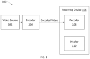
- FIG. 1 shows an exemplary video coding configuration.
- FIG. 2 shows an example technique for deriving the temporal derived motion vector predictions (MVPs).
- FIG. 3 shows an example technique of pattern-based motion vector derivation (PMVD) using bi-lateral matching merge mode.
- FIG. 4 shows an example of scaling a motion trajectory.
- FIG. 5 shows an example technique of pattern-based motion vector derivation (PMVD) using template matching merge mode.
- FIG. 6 shows an exemplary decoder architecture
- FIG. 7 shows an example of a decoder pipeline execution when executing a decoder architecture, such as the decoder architecture shown in FIG. 6 .
- FIG. 8 shows an example of a decoder pipeline execution when executing a decoder-side predictor refinement tool.
- Decoder-side predictor refinement tools can cause processing delays due to how the motion vectors are computed and reconstructed.
- the techniques described herein can allow for similar execution timing as compared to the execution of traditional decoding methods that do not predict motion vectors (e.g., such as when the motion vector information is signaled from the encoder).
- decoder-side predictor refinement techniques can be adjusted so that the motion vectors can be reconstructed early in the process, thereby allowing the decoder to pre-fetch the requisite reference pixels in a manner that hides the latency cycles required to fetch the data. Otherwise, if the decoder could not reconstruct the motion vectors early in the process, the decoder could not pre-fetch the reference data, which would typically cause a significant delay in execution throughput.
- the unrefined motion vector (MV) is (a) restored back into the MV buffer and/or (b) not changed, so that the unrefined MV can be used by the decoder-side MV refinement tools or used to derive the reference motion vector or the motion vector candidates (e.g. the merge candidate list and the advance motion vector predictor list) for the following blocks.
- the starting MV can be explicitly signaled by deriving a candidate list and signaling a candidate index.
- the MV can be derived in parsing stage without the influence of the decoder-side MV refinement tools, allowing the decoder to still pre-fetch the requisite information from the MV buffer.
- the decoder can use the signaled starting MV for merge candidate derivation and advanced motion vector prediction (AMVP) candidate derivation of the neighboring blocks.
- AMVP advanced motion vector prediction
- a coding tree unit (CTU)-row constraint can be incorporated so that the decoder can reference the modified MVs in the upper CTU-row.
- the decoder can be configured to not reference the MV of a PMVD coded block.
- both (a) the starting MV and (b) the coarse grain motion vector difference (MVD) can be signaled.
- the starting MV can be signaled by the AMVP mode (e.g., instead of a candidate list).
- AMVP mode e.g., instead of a candidate list.
- the decoder tests both the MV pair derived from LIST_ 0 and LIST_ 1 , but only stores one MV pair.
- the decoder only tests one MV pair derived from one list, and stores the MV pair of the tested list.
- FIG. 1 shows an exemplary video coding configuration 100 , according to some embodiments.
- Video source 102 is a video source, and can be, for example, digital television, internet-based video, video calling, and/or the like.
- Encoder 104 encodes the video source into encoded video.
- the encoder 104 can reside on the same device that generated the video source 102 (e.g., a cell phone, for video calling), and/or may reside on a different device.
- the receiving device 106 receives encoded video from the encoder 104 .
- the receiving device 104 may receive the video as a video product (e.g., a digital video disc, or other computer readable media), through a broadcast network, through a mobile network (e.g., a cellular network), and/or through the Internet.
- the receiving device 106 can be, for example, a computer, a cell phone, or a television.
- the receiving device 106 includes a decoder 108 that is configured to decode the encoded video.
- the receiving device 106 also includes a display 110 for displaying the decoded video.
- the decoder e.g., decoder 108 in the receiving device 106
- can employ receiver-side prediction tools often called receiver-side predictor refinement tools or decoder-side predictor refinement tools.
- An example of a receiver-side predictor refinement tool is Pattern-based Motion Vector Derivation (PMVD) mode, which may also be referred to as Frame Rate Up-Conversion (FRUC) mode.
- PMVD is described in, for example, Joint Video Exploration Team (WET) Document WET-F1001, entitled Algorithm Description of Joint Exploration Test Model 6 (JEM 6), which is hereby incorporated by reference herein in its entirety.
- decoder-side predictor refinement tools include bi-directional optical flow (BIO) and decoder-side motion vector refinement (DMVR).
- BIO was proposed by Samsung in the third JCTVC meeting and 52th VCEG meeting, and it is disclosed in the documents, JCTVC-C204 and VECG-AZ05. See, e.g., Maria Alshina and Alexander Alshin, Bi-Directional Optical Flow, Oct. 7-15, 2010 (JCTVC-C204) (including the two attached Microsoft Excel spreadsheets), and E. Alshina et al., Known Tools Performance Investigation for Next Generation Video Coding, Jun.
- BIO utilizes the assumptions of optical flow and steady motion to achieve the sample-level motion refinement. It is typically applied only for truly bi-directional predicted blocks, which is predicted from two reference frames and one is the previous frame and the other is the latter frame.
- BIO utilizes one 5 ⁇ 5 window to derive the motion refinement of one sample, so for one N ⁇ N block, the motion compensated results and corresponding gradient information of one (N+4) ⁇ (N+4) block are required to derive the sample-based motion refinement of current block.
- one 6-Tap gradient filter and one 6-Tap interpolation filter are used to generate the gradient information in BIO.
- BIO Context-Based Adaptive Binary Arithmetic Coding in the H.264/AVC Video Compression Standard, IEEE Transactions on Circuits and Systems for Video Technology, Vol. 13, No. 7, pp. 620-636, July 2003, incorporated by reference herein in its entirety.
- PMVD itself can be performed using different modes such as, for example, bi-lateral matching merge mode or template matching merge mode.
- which mode for the decoder to use is signaled in the encoded video.
- the encoder signals to the decoder to use PMVD mode, and also signals which particular PMVD mode.
- a FRUC_mrg_flag is signaled when the merge_flag or skip_flag is true. If the FRUC_mrg_flag is 1 , then a FRUC_merge_mode is signaled to indicate whether the bilateral matching merge mode (e.g., described further in conjunction with FIGS. 2 - 4 ) or template matching merge mode (e.g., described further in conjunction with FIG. 5 ) is selected.
- the bilateral matching merge mode e.g., described further in conjunction with FIGS. 2 - 4
- template matching merge mode e.g., described further in conjunction with FIG. 5
- both PMVD modes use decoded pixels to derive the motion vector for the current block.
- a new temporal motion vector prediction (MVP) called temporal derived MVP is derived by scanning all MVs in all reference frames.
- a picture often refers to a number of frames (e.g., one picture includes sixteen frames). Those reference frames are put into one or two reference picture list.
- P-slice only one reference picture list is used.
- B-slice two reference picture lists are used.
- two reference picture lists are used to store past and future pictures, which are often referred to as LIST_ 0 for past pictures and LIST_ 1 for future pictures.
- the MV is scaled to point to the current frame.
- the block that is pointed by the scaled MV in the current frame is the target current block.
- the MV is further scaled to point to the reference picture for which refldx is equal to 0 in LIST_ 0 for the target current block.
- the further scaled MV is stored in the LIST_ 0 MV field for the target current block.
- FIG. 2 shows an example 200 of deriving the temporal derived MVPs.
- the decoder scans all the LIST_ 0 MVs in LIST_ 0 reference pictures for which the refldx is equal to 1.
- a scaled MV that points to the current picture is derived for each LIST_ 0 MV (shown by dotted arrows 206 and 208 for reference picture 201 ).
- a 4 ⁇ 4 block 210 , 212 in the current picture 205 is pointed to by each of the scaled MVs.
- another scaled MV 214 , 216 is assigned to the pointed 4 ⁇ 4 blocks 210 , 212 , respectively, in current picture where the scaled MV 214 , 216 is along the associated scaled MV 202 , 204 but the start point is the current picture 205 and the end point is the reference picture 218 with refldx equal to 0 in LIST_ 0 .
- the decoder scans all the MVs in all 4 ⁇ 4 blocks in all reference pictures to generate the temporal derived LIST_ 0 and LIST_ 1 MVPs of current frame. For each MV, the MV is scaled to get the crossed block in current picture. The decoder then calculates the scaled MVP and assigns it to the crossed block (as shown as the block pointed by the dotted arrows 206 , 208 ).
- FIG. 3 shows an example of PMVD bilateral matching merge mode.
- the decoder finds the two most similar reference blocks in LIST_ 0 and LIST_ 1 that lie in the same trajectory.
- the decoder selects one macroblock (or “block”) 302 in reference frame Ref 0 304 from LIST_ 0 and a second block 306 in reference frame Ref 1 308 from LIST_ 1 .
- the decoder essentially assumes motion is constant, and uses the middle point of both macroblocks to generate motion trajectory 310 .
- the decoder uses the motion trajectory 310 to find the current prediction macroblock (or “block”) 312 in cur pic 300 .
- the decoder calculates the difference between block 302 and block 306 . If there is only a small difference, then the decoder knows that the blocks are very similar. In some examples, the decoder can calculate the sum of absolute distance (or “SAD”) to calculate the difference between the two blocks. The decoder changes the motion trajectory to minimize the difference between the blocks.
- SAD sum of absolute distance
- the decoder constructs the starting motion vector (MV) list in LIST_ 0 and LIST_ 1 , respectively.
- the decoder uses eleven candidates for the list, including seven MVs of merge candidates and four temporally derived MV predictions (or MVPs).
- the decoder evaluates these eleven candidates to select the best starting point. In particular, the decoder searches for a pair across the two neighboring frames.
- the decoder analyzes the 22 motion vectors to derive 22 motion vector pairs.
- the decoder generates the MV pairs by scaling the motion trajectory. For each MV in one list, a MV pair is generated by composing of this MV and the mirrored MV that is derived by scaling the MV to the other list.
- FIG. 4 shows an example 400 of scaling a motion trajectory.
- the motion trajectory 402 from the Cur pic to ref 1 in LIST_ 0 is scaled as shown with motion trajectory 404 from Cur pic to ref 0 in LIST_ 1 .
- the decoder calculates a cost for each of the 22 motion vector pairs (e.g., using SAD) and selects the MV pair with the smallest cost as the starting point of bilateral matching merge mode.
- the decoder next refines the selected MV pair.
- the decoder searches different blocks around the starting point to decide which block is the best match.
- the current PU is divided into sub-PUs.
- the depth of sub-PU is signaled in sequence parameter set, SPS (e.g. 3 ).
- the minimum sub-PU size is a 4 ⁇ 4 block.
- For each sub-PU several starting MVs in LIST_ 0 and LIST_ 1 are selected, which includes MVs of PU-level derived MV, zero MV, HEVC collocated TMVP of current sub-PU and bottom-right block, temporal derived MVP of current sub-PU, and MVs of left and above PUs/sub-PUs.
- the decoder uses a Diamond Search algorithm to search the different blocks. Then the final MV pair is used as the PU-level and sub-PU-level best MV pair.
- the bilateral matching merge mode uses the MV lists first, evaluates the candidate MV pairs to get starting MV pair, and then refines the pair to determine the ultimate best MV pair.
- FIG. 5 shows an example technique for template matching merge mode.
- the template 502 includes the reconstructed pixels from four rows above the current block 504 and from four columns to the left of the current block 504 to perform the matching in Ref 0 506 for Cur Pic 508 . Therefore, unlike bilateral matching merge mode, template matching merge mode does not use two reference frames—it just uses one reference frame.
- two-stage matching is also applied for template matching.
- eleven starting MVs in LIST_ 0 and LIST_ 1 are selected respectively. These MVs include seven MVs from merge candidates and four MVs from temporal derived MVPs.
- Two different staring MV sets are generated for two lists. For each MV in one list, the SAD cost of the template with the MV is calculated. The MV with the smallest cost is the best MV. Then, the diamond search is performed to refine the MV. The refinement precision is 1 ⁇ 8-pel.
- the refinement search range is restricted within ⁇ 8 pixels.
- the final MV is the PU-level derived MV.
- the MVs in LIST_ 0 and LIST_ 1 are generated independently.
- the current PU is divided into sub-PUs.
- the depth of sub-PU is signaled in SPS (e.g. 3 ).
- Minimum sub-PU size is 4 ⁇ 4 block.
- several starting MVs in LIST_ 0 and LIST_ 1 are selected, which includes MVs of PU-level derived MV, zero MV, HEVC collocated TMVP of current sub-PU and bottom-right block, temporal derived MVP of current sub-PU, and MVs of left and above PUs/sub-PUs.
- the best MV pair for the sub-PU is selected.
- the diamond search is performed to refine the MV pair.
- the motion compensation for this sub-PU is performed to generate the predictor for this sub-PU.
- the second stage, sub-PU-level searching, is not applied, and the corresponding MVs are set equal to the MVs in the first stage.
- FIG. 6 shows an exemplary decoder architecture 600 , according to some embodiments.
- the Entropy Decoder includes, e.g., a CABAC or CAVLC entropy decoder, which parses the syntaxes from the bitstream.
- the ColMV DMA 610 stores the collocated temporal MVs.
- the MV Dispatch 612 reconstructs the MVs of the blocks and issues the memory fetch instruction to the MC cache 614 and DRAM (not shown) through the memory interface arbiter 616 .
- the Inverse Transform 618 includes inverse quantization and inverse transform (IQIT) that generates the reconstructed residual 620 .
- Prediction block 622 generates the inter motion compensation and intra prediction predictors.
- Deblock 624 is to reduce the block artifact and the Rec DMA 626 stores the reconstructed pixels to the external DRAM. Further detail of exemplary components of this architecture is discussed in C.-T. Huang et al., “A 249MPixel/s HEVC video-decoder chip for Quad Full HD applications,” Digest of Technical Papers IEEE International Solid-State Circuits Conference (ISSCC), pp. 162-163, February 2013, which is hereby incorporated by reference herein in its entirety. Of note, the architecture is broken up into four stages in order to pipeline the architecture: the EC stage 602 , the IQIT (inverse quantization and inverse transform)/fetch stage 604 , the reconstruction stage 606 and the loop filter stage 608 .
- the EC stage 602 the IQIT (inverse quantization and inverse transform)/fetch stage 604
- the reconstruction stage 606 the loop filter stage 608 .
- the final MV can be derived in both the EC stage 602 (which includes parsing) and the reconstruction stage 606 .
- the decoder derives the final MV in the parsing stage, and pre-fetches the required reference pixel data in the parsing stage (EC stage 602 ). This can be done, for example, to reduce/hide the DRAM access time.
- FIG. 7 shows an example of a decoder pipeline execution 700 when executing a decoder architecture, such as the decoder architecture shown in FIG. 6 , according to some embodiments.
- FIG. 7 includes the parsing stage 702 , during which the motion vectors are reconstructed as described above.
- the IQ/IT stage 704 - 1 generates the reconstructed residual for the current block.
- the Reference Pixels Fetch stage 704 - 2 fetches reference pixel data from memory. Reference frames are often stored in external memory, such as DRAM. Thus, if the decoder wants to do motion compensation on a reference frame, the decoder first needs to go to external memory to retrieve the reference data. Typically a lot of latency time is required to get data from external memory.
- the Intra/MC (Motion Compensation) reconstruction stage 706 performs the prediction.
- the deblocking (DB)/Sample Adaptive Offset (SAO) stage 708 performs in-loop filtering process to improve the quality of the de
- the decoder first decodes CU 0 , then CU 1 and so forth. To give an example using CU 0 , at t 0 , the decoder decodes CU 0 in the parsing stage 702 including reconstructing the MVs. Then, at t 1 CU 0 moves to IQ/IT stage 704 - 1 . In order to do motion compensation in the Intra/MC Reconstruction stage 706 , the decoder needs to do a pre-fetch in the previous stage (the Ref Pixels fetch stage 704 - 2 ).
- the data is pre-fetched in the Ref Pixels fetch stage 704 - 2 and stored in local memory (e.g., SRAM or cache memory).
- local memory e.g., SRAM or cache memory.
- the MVs can be reconstructed in the parsing stage.
- the required reference pixels can be fetched from the DRAM and stored in the local memory, e.g. SRAM or cache memory.
- the reference data can be loaded from the local memory without latency cycles.
- decoder-side predictor refinement tools use the neighboring block(s) to derive the motion vector (e.g., PMVD, such as how template matching merge mode uses the neighboring block to derive motion vector).
- PMVD such as how template matching merge mode uses the neighboring block to derive motion vector
- the template block is not generated until the third stage (the Intra/MC Reconstruction stage 706 ).
- the final MVs of a PMVD coded block depend on the PMVD searching process in the Intra/MC Reconstruction stage 706 , which means the MVs cannot be reconstructed in the Parsing stage 702 , and therefore the data pre-fetch is not feasible at stage Ref Pixels fetch 704 - 2 .
- FIG. 8 shows an example of a decoder pipeline execution when executing a decoder-side predictor refinement tool.
- PMVD the MVs for CU 0 depend on the PMVD searching process in the Intra/MC Reconstruction stage 706 (which is also performed at t 2 )
- the MVs cannot be reconstructed in the Parsing stage 702 for CU 01 (at time t 1 ), and so the data cannot be pre-fetched for CU 1 at t 2 at stage Ref Pixels fetch 704 - 2 .
- This problem similarly affects the processing of each CU, and therefore results ultimately in only one CU processing finishing per two time slots.
- FIG. 8 shows that for t 4 and t 5 , the decoder only completes processing CU 1 , compared to FIG. 7 , where CU 1 completes processing at t 4 and CU 2 completes processing at t 5 .
- the techniques disclosed herein address such data pre-fetch issues when decoder-side prediction refinement techniques (e.g., PMVD) are used for decoding.
- PMVD decoder-side prediction refinement techniques
- the techniques allow the data to be pre-fetched in a manner that still hides the latency cycles, such as shown in FIG. 7 , rather than causing a delay as shown in FIG. 8 .
- the discussion below refers to PMVD as an example, although a person of skill can appreciate that the techniques can be adapted for other decoder-side prediction refinement techniques (e.g., BIO and DMVR).
- the original candidate MV is preserved in the MV buffer for the next decoding process.
- the selected merge candidate MVs e.g., the starting, or unrefined MVs
- the MC of the PMVD block uses the PMVD derived MVs, but the selected merge candidate MVs are stored back to the MV buffers for the future referencing.
- the MVs can be reconstructed in Parsing stage 702 , and the reference pixels can be pre-fetched at stage 704 - 2 .
- the current block is a PMVD coded block
- a larger reference block e.g., including the refinement search range
- the MV is not refined for the current block, but the decoder uses the refined MV for compensation.
- the decoder can be configured not to change the MV in the MV buffer.
- the decoder can store the starting point (e.g., the starting MV(s)) in the MV buffer, and do the refinement to generate a refinement MV that is only used to generate motion compensation data, without changing the MV in the MV buffer.
- the MV buffers for the future referencing e.g. the merge candidate list and AMVP candidate list generation
- the decoder can use a separate buffer for refinement. For example, the decoder can retrieve the starting MV, run PMVD and execute refinement without storing the refined MV in the original MV buffer—the decoder stores the refined MV in a temporal buffer.
- the decoder can signal a starting candidate for PMVD.
- the decoder can signal a starting candidate index that is used to select a starting MV from a MV candidate list. This can be done, for example, so that the decoder knows which candidate out of the eleven candidates will be used as the starting candidate for PMVD.
- the decoder can first generate the eleven starting candidates, and the encoder can signal to the decoder which is best. This signaling can allow, for example, the decoder to skip template matching and to proceed right to the refinement since the decoder knows staring candidate (e.g., the decoder can perform refinement using template matching and the Diamond Search technique to refine the MV around the starting candidate). While the MV is will be refined by diamond search, in proposed method will only store the starting candidate, not the refined motion vector.
- the LIST_ 0 and LIST_ 1 MVs in merge candidates are used as starting MVs.
- a best MV candidate can be implicitly derived by searching all these MVs. This can require a lot of memory bandwidth.
- the merge index for bilateral matching merge mode or template matching merge mode is signaled.
- the signaled merge index can indicate, for example, the best starting MVs in LIST_ 0 and LIST_ 1 in template matching merge mode, and the best two MV pairs (one is derived from the LIST_ 0 and the other is derived from the LIST_ 1 ) in bilateral matching merge mode.
- the template matching step can be limited to, e.g., a refinement search around the signaled merge candidate.
- the decoder can perform cost estimation to select the best MV pair from the two MV pairs and perform the refinement search.
- the merge candidate is a uni-directional MV
- its corresponding MV in another list can be generated by using the mirrored (scaled) MV.
- the starting MVs in LIST_ 0 , LIST_ 1 , and/or the MV pairs are known.
- the best starting MVs in LIST_ 0 and/or LIST_ 1 , or the best MV pair are explicitly signaled to reduce the bandwidth requirement.
- the decoder can further utilize the selected MV to exclude or select some candidates in the first stage (PU-level Matching). For example, the decoder can exclude some MVs in the candidate list which are far from the selected MVs. As another example, the decoder can pick N MVs in the candidate list that are the most close to the selected MV but in different reference frames.
- the starting MV candidate might be a MV pair (one MV for LIST_ 0 and another MV for LIST_ 1 ). Two MV pairs are derived from the starting MV pair (e.g., one is derived from the LIST_ 0 MV and the other is derived from the LIST_ 1 MV).
- the decoder can be configured to test both LIST_ 0 and LIST_ 1 MV pairs, but only stores one MV pair. In some examples, the decoder can be configured to always store either LIST_ 0 or LIST_ 1 MV pair.
- the stored LIST_ 0 MV is the LIST_ 0 MV of the merge candidate MV and the stored LIST_ 1 MV is the mirrored MV of the LIST_ 0 MV.
- the decoder can evaluate the MV pairs in both lists, but only the LIST_ 0 MV and its mirrored MV are stored back.
- the stored LIST_ 1 MV is the LIST_ 1 MV of the merge candidate MV and the stored LIST_ 0 MV is the mirrored MV of the LIST_ 1 MV.
- the decoder can be configured store the one of LIST_ 0 or LIST_ 1 MV pair with the smaller delta picture order count (POC). For example, if the POC difference between the LIST_ 0 reference picture and the current picture is smaller than (or equal to) the POC difference between the LIST_ 1 reference picture and the current picture, the stored LIST_ 0 MV is the LIST_ 0 MV of the merge candidate MV and the stored LIST_ 1 MV is the mirrored MV of the LIST_ 0 MV. Otherwise, the stored LIST_ 1 MV is the LIST_ 1 MV of the merge candidate MV and the stored LIST 0 MV is the mirrored MV of the LIST_ 1 MV.
- POC difference between the LIST_ 0 reference picture and the current picture is smaller than (or equal to) the POC difference between the LIST_ 1 reference picture and the current picture
- the stored LIST_ 0 MV is the LIST_ 0 MV of the merge candidate MV and the stored LIST_ 1
- the stored LIST_ 0 MV is the LIST_ 0 MV of the merge candidate MV and the stored LIST_ 1 MV is the mirrored MV of the LIST_ 0 MV. If the selected merge candidate MV is a uni-predicted LIST_ 1 MV, the stored LIST_ 1 MV is the LIST_ 1 MV of the merge candidate MV and the stored LIST_ 0 MV is the mirrored MV of the LIST_ 1 MV.
- the decoder when bilateral matching mode is applied, can be configured to only test one of LIST_ 0 or LIST_ 1 MV pair. For example, if the selected merge candidate MV is a bi-predicted MV, the decoder can be configured to only evaluate the LIST_ 0 MV pair. The PMVD starting LIST_ 0 MV is the selected merge candidate LIST_ 0 MV and the LIST_ 1 MV is the mirrored LIST_ 0 MV. In this example, the original LIST_ 1 MV is not evaluated in PMVD. In another example, when bilateral matching mode is applied and the selected merge candidate MV is a bi-predicted MV, the decoder can be configured to only use the LIST_ 1 MV pair.
- the PMVD starting LIST_ 1 MV is the selected merge candidate LIST_ 1 MV and the LIST_ 0 MV is the mirrored LIST_ 1 MV.
- the decoder can be configured to only use the MV pair of the LIST with the reference picture that has smaller POC. For example, if the POC difference between the LIST_ 0 reference picture and the current picture is smaller than (or equal to) the POC difference between the LIST_ 1 reference picture and the current picture, the LIST_ 0 MV and its mirrored MV in LIST_ 1 is used. Otherwise, the LIST_ 1 MV and its mirrored MV in LIST_ 0 is used.
- the decoder can be configured to not refer to the MVs of PMVD coded blocks.
- the decoder can treat the PMVD coded blocks as, e.g., not available or as intra coded blocks.
- the PMVD derived MVs are not available in merge candidate derivation and AMVP candidate derivation.
- the MV reconstruction is independent to the PMVD.
- the MVs can be reconstructed in parsing stage.
- a MV search method can be predefined (e.g., a three step diamond search).
- the step size of the first step diamond search is half of one pixel (half-pixel).
- the step size of the second step cross search is one quarter of one pixel (quarter-pixel).
- the step size of the third step cross search is 1 ⁇ 8 of one pixel (1 ⁇ 8 pixel).
- both (a) the merge index of the staring MV and (b) a coarse grain MVD are signaled.
- the MVD can be the refinement position index of the first step diamond search, and/or a conventional MVD.
- the MVD unit can be 1/16-pixel, 1 ⁇ 8-pixel, quarter-pixel, half-pixel, one-pixel, two-pixel, or any predefined unit.
- the MVs of the selected merge index plus the signaled MVD (or the MV of the refinement position) can be used as the PMVD starting MV, which are stored into the MV buffer for merge candidate and AMVP candidate derivation referencing.
- the PMVD search can start from the PMVD starting MV.
- the final PMVD derived MV is only for the MC.
- the starting MVs of the PMVD coded block can be reconstructed in parsing stage.
- only one MVD, and/or only one MVD refinement position index is signaled. If the merge candidate is a bi-predicted candidate, the MVD is added only on the LIST_ 0 or LIST_ 1 . For bilateral matching merge mode, if the MVD is added on the LIST_ 0 , the LIST_ 1 starting MV can be the mirrored MV of the LIST_ 0 starting MV.
- coarse grain MVD is not coded but derived in the search process at decoder. For example, we can partition the search process into three stages, the first step diamond search, the second step cross search, and the third step cross search.
- the coarse grain MVD can be the result of search process in the first step diamond search or the second step cross search.
- the MVP and MVD are signaled for a PU.
- the system can be configured to apply the PMVD for the AMVP mode.
- an additional flag can be signaled for the AMVP PU to indicate whether the PMVD is applied (or not).
- the PMVD starts from the signaled MV of the AMVP mode, e.g., such that the starting MV is signaled by AMVP mode (e.g., rather than a candidate list).
- the PMVD refinement range can be restricted to be smaller than the unit/granularity of the MVD. In some examples, if the PMVD is applied, the MVD is in a coarser granularity than the normal AMVP mode.
- the MVD granularity is changed to half-pixel or integer-pixel.
- the PMVD refinement range is restricted to be smaller than +-half-pixel or +-one-pixel.
- the PMVD flag can be signaled in CU-level, CTU-level, some predefined area-level, slice-level, picture-level, or sequence-level. If the PMVD flag is signaled in CTU-level and the flag is true, the PMVD is applied to all the AMVP mode coded PU in the CTU. For the predefined area-level, the PMVD flag is signaled for the CU/PU larger than or equal to the predefined area. This flag can also be shared for the CU/PU smaller than the predefined area.
- the PMVD derived MVs can only be used for MC.
- the signaled MVs (MVP+MVD) can be stored in the MV buffer for referencing.
- a picture is divided into coding tree units (CTUs), which are the basic processing unit for HEVC.
- the CTUs are coded in raster scan order.
- most information of the upper CTU rows is available in parsing stage (e.g., including the MV information) since the row was already processed.
- the decoder-side derived MVs in CTUs from the upper CTU-row can be referenced (or used), for example, for merge candidate list and AMVP list generation, since the information is available in the parsing stage.
- the decoder can use the derived MVs in those CTUs even though the decoder-side derived MVs in current CTU-row cannot be used since they are not available.
- a CTU-row constraint can be used with the techniques described herein, such that the PMVD derived MVs in upper CTU-row can be referred to (e.g. when not referring to the MV of the PMVD coded block) or can be used (e.g. when storing the merge candidate MVs, storing the merge candidate MVs and mirrored MV, sending the merge index for PMVD and bilateral mirrored MV (and only evaluating one MV), signaling the merge index and coarse grain MVD, and/or AMVP mode and PMVD).
- the merge candidate MVs can be used for merge candidate derivation and AMVP candidate derivation.
- the final PMVD derived MVs can be used.
- the MVs are not available for merge candidate derivation and AMVP candidate derivation.
- the final PMVD derived MVs are used.
- the CTU-row constraint can be changed to CTU constraint or any predefined or derived area constraint. For example, when not referring to the MV of the PMVD coded block, if the CTU constraint is applied, the MVs of PMVD coded blocks in the current CTU are not available while the MVs of the PMVD coded blocks in different CTUs are available.
- the techniques described herein may be embodied in computer-executable instructions implemented as software, including as application software, system software, firmware, middleware, embedded code, or any other suitable type of computer code.
- Such computer-executable instructions may be written using any of a number of suitable programming languages and/or programming or scripting tools, and also may be compiled as executable machine language code or intermediate code that is executed on a framework or virtual machine.
- these computer-executable instructions may be implemented in any suitable manner, including as a number of functional facilities, each providing one or more operations to complete execution of algorithms operating according to these techniques.
- a “functional facility,” however instantiated, is a structural component of a computer system that, when integrated with and executed by one or more computers, causes the one or more computers to perform a specific operational role.
- a functional facility may be a portion of or an entire software element.
- a functional facility may be implemented as a function of a process, or as a discrete process, or as any other suitable unit of processing.
- each functional facility may be implemented in its own way; all need not be implemented the same way.
- these functional facilities may be executed in parallel and/or serially, as appropriate, and may pass information between one another using a shared memory on the computer(s) on which they are executing, using a message passing protocol, or in any other suitable way.
- functional facilities include routines, programs, objects, components, data structures, etc. that perform particular tasks or implement particular abstract data types.
- functionality of the functional facilities may be combined or distributed as desired in the systems in which they operate.
- one or more functional facilities carrying out techniques herein may together form a complete software package.
- These functional facilities may, in alternative embodiments, be adapted to interact with other, unrelated functional facilities and/or processes, to implement a software program application.
- Some exemplary functional facilities have been described herein for carrying out one or more tasks. It should be appreciated, though, that the functional facilities and division of tasks described is merely illustrative of the type of functional facilities that may implement the exemplary techniques described herein, and that embodiments are not limited to being implemented in any specific number, division, or type of functional facilities. In some implementations, all functionality may be implemented in a single functional facility. It should also be appreciated that, in some implementations, some of the functional facilities described herein may be implemented together with or separately from others (i.e., as a single unit or separate units), or some of these functional facilities may not be implemented.
- Computer-executable instructions implementing the techniques described herein may, in some embodiments, be encoded on one or more computer-readable media to provide functionality to the media.
- Computer-readable media include magnetic media such as a hard disk drive, optical media such as a Compact Disk (CD) or a Digital Versatile Disk (DVD), a persistent or non-persistent solid-state memory (e.g., Flash memory, Magnetic RAM, etc.), or any other suitable storage media.
- Such a computer-readable medium may be implemented in any suitable manner.
- “computer-readable media” also called “computer-readable storage media” refers to tangible storage media. Tangible storage media are non-transitory and have at least one physical, structural component.
- At least one physical, structural component has at least one physical property that may be altered in some way during a process of creating the medium with embedded information, a process of recording information thereon, or any other process of encoding the medium with information. For example, a magnetization state of a portion of a physical structure of a computer-readable medium may be altered during a recording process.
- some techniques described above comprise acts of storing information (e.g., data and/or instructions) in certain ways for use by these techniques.
- the information may be encoded on a computer-readable storage media.
- advantageous structures may be used to impart a physical organization of the information when encoded on the storage medium. These advantageous structures may then provide functionality to the storage medium by affecting operations of one or more processors interacting with the information; for example, by increasing the efficiency of computer operations performed by the processor(s).
- these instructions may be executed on one or more suitable computing device(s) operating in any suitable computer system, or one or more computing devices (or one or more processors of one or more computing devices) may be programmed to execute the computer-executable instructions.
- a computing device or processor may be programmed to execute instructions when the instructions are stored in a manner accessible to the computing device or processor, such as in a data store (e.g., an on-chip cache or instruction register, a computer-readable storage medium accessible via a bus, a computer-readable storage medium accessible via one or more networks and accessible by the device/processor, etc.).
- a data store e.g., an on-chip cache or instruction register, a computer-readable storage medium accessible via a bus, a computer-readable storage medium accessible via one or more networks and accessible by the device/processor, etc.
- Functional facilities comprising these computer-executable instructions may be integrated with and direct the operation of a single multi-purpose programmable digital computing device, a coordinated system of two or more multi-purpose computing device sharing processing power and jointly carrying out the techniques described herein, a single computing device or coordinated system of computing device (co-located or geographically distributed) dedicated to executing the techniques described herein, one or more Field-Programmable Gate Arrays (FPGAs) for carrying out the techniques described herein, or any other suitable system.
- FPGAs Field-Programmable Gate Arrays
- a computing device may comprise at least one processor, a network adapter, and computer-readable storage media.
- a computing device may be, for example, a desktop or laptop personal computer, a personal digital assistant (PDA), a smart mobile phone, a server, or any other suitable computing device.
- PDA personal digital assistant
- a network adapter may be any suitable hardware and/or software to enable the computing device to communicate wired and/or wirelessly with any other suitable computing device over any suitable computing network.
- the computing network may include wireless access points, switches, routers, gateways, and/or other networking equipment as well as any suitable wired and/or wireless communication medium or media for exchanging data between two or more computers, including the Internet.
- Computer-readable media may be adapted to store data to be processed and/or instructions to be executed by processor. The processor enables processing of data and execution of instructions. The data and instructions may be stored on the computer-readable storage media.
- a computing device may additionally have one or more components and peripherals, including input and output devices. These devices can be used, among other things, to present a user interface. Examples of output devices that can be used to provide a user interface include printers or display screens for visual presentation of output and speakers or other sound generating devices for audible presentation of output. Examples of input devices that can be used for a user interface include keyboards, and pointing devices, such as mice, touch pads, and digitizing tablets. As another example, a computing device may receive input information through speech recognition or in other audible format.
- Embodiments have been described where the techniques are implemented in circuitry and/or computer-executable instructions. It should be appreciated that some embodiments may be in the form of a method, of which at least one example has been provided. The acts performed as part of the method may be ordered in any suitable way. Accordingly, embodiments may be constructed in which acts are performed in an order different than illustrated, which may include performing some acts simultaneously, even though shown as sequential acts in illustrative embodiments.
- exemplary is used herein to mean serving as an example, instance, or illustration. Any embodiment, implementation, process, feature, etc. described herein as exemplary should therefore be understood to be an illustrative example and should not be understood to be a preferred or advantageous example unless otherwise indicated.
Abstract
Description
Claims (19)
Priority Applications (5)
| Application Number | Priority Date | Filing Date | Title |
|---|---|---|---|
| US15/670,109 US11638027B2 (en) | 2016-08-08 | 2017-08-07 | Pattern-based motion vector derivation for video coding |
| CN201780047558.7A CN109565590B (en) | 2016-08-08 | 2017-08-08 | Model-based motion vector derivation for video coding |
| TW106126691A TWI669953B (en) | 2016-08-08 | 2017-08-08 | Pattern-based motion vector derivation for video coding |
| PCT/CN2017/096382 WO2018028559A1 (en) | 2016-08-08 | 2017-08-08 | Pattern-based motion vector derivation for video coding |
| US18/167,355 US20230188745A1 (en) | 2016-08-08 | 2023-02-10 | Pattern-based motion vector derivation for video coding |
Applications Claiming Priority (2)
| Application Number | Priority Date | Filing Date | Title |
|---|---|---|---|
| US201662371879P | 2016-08-08 | 2016-08-08 | |
| US15/670,109 US11638027B2 (en) | 2016-08-08 | 2017-08-07 | Pattern-based motion vector derivation for video coding |
Related Child Applications (1)
| Application Number | Title | Priority Date | Filing Date |
|---|---|---|---|
| US18/167,355 Continuation US20230188745A1 (en) | 2016-08-08 | 2023-02-10 | Pattern-based motion vector derivation for video coding |
Publications (2)
| Publication Number | Publication Date |
|---|---|
| US20180041769A1 US20180041769A1 (en) | 2018-02-08 |
| US11638027B2 true US11638027B2 (en) | 2023-04-25 |
Family
ID=61070173
Family Applications (2)
| Application Number | Title | Priority Date | Filing Date |
|---|---|---|---|
| US15/670,109 Active US11638027B2 (en) | 2016-08-08 | 2017-08-07 | Pattern-based motion vector derivation for video coding |
| US18/167,355 Pending US20230188745A1 (en) | 2016-08-08 | 2023-02-10 | Pattern-based motion vector derivation for video coding |
Family Applications After (1)
| Application Number | Title | Priority Date | Filing Date |
|---|---|---|---|
| US18/167,355 Pending US20230188745A1 (en) | 2016-08-08 | 2023-02-10 | Pattern-based motion vector derivation for video coding |
Country Status (4)
| Country | Link |
|---|---|
| US (2) | US11638027B2 (en) |
| CN (1) | CN109565590B (en) |
| TW (1) | TWI669953B (en) |
| WO (1) | WO2018028559A1 (en) |
Families Citing this family (72)
| Publication number | Priority date | Publication date | Assignee | Title |
|---|---|---|---|---|
| US11343530B2 (en) * | 2016-11-28 | 2022-05-24 | Electronics And Telecommunications Research Institute | Image encoding/decoding method and device, and recording medium having bitstream stored thereon |
| US20180192071A1 (en) * | 2017-01-05 | 2018-07-05 | Mediatek Inc. | Decoder-side motion vector restoration for video coding |
| US20180199057A1 (en) * | 2017-01-12 | 2018-07-12 | Mediatek Inc. | Method and Apparatus of Candidate Skipping for Predictor Refinement in Video Coding |
| WO2018212111A1 (en) | 2017-05-19 | 2018-11-22 | パナソニック インテレクチュアル プロパティ コーポレーション オブ アメリカ | Encoding device, decoding device, encoding method and decoding method |
| CN117615153A (en) * | 2017-08-29 | 2024-02-27 | 株式会社Kt | Video decoding and encoding method and apparatus for storing compressed video data |
| US10785494B2 (en) | 2017-10-11 | 2020-09-22 | Qualcomm Incorporated | Low-complexity design for FRUC |
| US10798402B2 (en) * | 2017-10-24 | 2020-10-06 | Google Llc | Same frame motion estimation and compensation |
| JP7315480B2 (en) * | 2018-01-30 | 2023-07-26 | パナソニック インテレクチュアル プロパティ コーポレーション オブ アメリカ | Encoding device, decoding device, encoding method and decoding method |
| US11563970B2 (en) * | 2018-02-26 | 2023-01-24 | Interdigital Vc Holdings, Inc. | Method and apparatus for generalized OBMC |
| US10779002B2 (en) * | 2018-04-17 | 2020-09-15 | Qualcomm Incorporated | Limitation of the MVP derivation based on decoder-side motion vector derivation |
| WO2019201264A1 (en) * | 2018-04-18 | 2019-10-24 | Mediatek Inc. | Candidate reorganizing with advanced control in video coding |
| JP7395497B2 (en) | 2018-05-07 | 2023-12-11 | インターデジタル ヴイシー ホールディングス, インコーポレイテッド | Data dependencies in encoding/decoding |
| EP3591974A1 (en) * | 2018-07-02 | 2020-01-08 | InterDigital VC Holdings, Inc. | Data dependency in encoding/decoding |
| US11470346B2 (en) * | 2018-05-09 | 2022-10-11 | Sharp Kabushiki Kaisha | Systems and methods for performing motion vector prediction using a derived set of motion vectors |
| CN112399184B (en) | 2018-05-16 | 2022-07-12 | 华为技术有限公司 | Motion vector acquisition method, device, equipment and computer readable storage medium |
| EP3804325A1 (en) * | 2018-05-28 | 2021-04-14 | InterDigital VC Holdings, Inc. | Data dependency in coding/decoding |
| US10798407B2 (en) * | 2018-06-01 | 2020-10-06 | Tencent America LLC | Methods and apparatus for inter prediction with a reduced above line buffer in video coding |
| US10469869B1 (en) * | 2018-06-01 | 2019-11-05 | Tencent America LLC | Method and apparatus for video coding |
| GB2589222B (en) | 2018-06-07 | 2023-01-25 | Beijing Bytedance Network Tech Co Ltd | Sub-block DMVR |
| US10863190B2 (en) * | 2018-06-14 | 2020-12-08 | Tencent America LLC | Techniques for memory bandwidth optimization in bi-predicted motion vector refinement |
| CN112292854A (en) * | 2018-06-18 | 2021-01-29 | 世宗大学校产学协力团 | Image encoding/decoding method and apparatus |
| US10965951B2 (en) | 2018-06-22 | 2021-03-30 | Avago Technologies International Sales Pte. Limited | Memory latency management for decoder-side motion refinement |
| EP3815374A1 (en) * | 2018-06-27 | 2021-05-05 | Vid Scale, Inc. | Methods and apparatus for reducing the coding latency of decoder-side motion refinement |
| CN110662070B (en) | 2018-06-29 | 2022-03-18 | 北京字节跳动网络技术有限公司 | Selection of coded motion information for look-up table update |
| JP7460617B2 (en) | 2018-06-29 | 2024-04-02 | 北京字節跳動網絡技術有限公司 | LUT update conditions |
| CN115988203A (en) | 2018-06-29 | 2023-04-18 | 北京字节跳动网络技术有限公司 | Method, apparatus, computer-readable storage medium for video processing |
| CN114845108A (en) | 2018-06-29 | 2022-08-02 | 抖音视界(北京)有限公司 | Updating the lookup table: FIFO, constrained FIFO |
| WO2020003270A1 (en) | 2018-06-29 | 2020-01-02 | Beijing Bytedance Network Technology Co., Ltd. | Number of motion candidates in a look up table to be checked according to mode |
| TWI723444B (en) | 2018-06-29 | 2021-04-01 | 大陸商北京字節跳動網絡技術有限公司 | Concept of using one or multiple look up tables to store motion information of previously coded in order and use them to code following blocks |
| CN110662043B (en) | 2018-06-29 | 2021-12-21 | 北京字节跳动网络技术有限公司 | Method, apparatus and computer readable medium for processing video data |
| CN110662064B (en) | 2018-06-29 | 2022-06-14 | 北京字节跳动网络技术有限公司 | Checking order of motion candidates in LUT |
| GB2589241B (en) | 2018-07-02 | 2023-06-07 | Beijing Bytedance Network Tech Co Ltd | Update of look-up tables |
| TWI719519B (en) | 2018-07-02 | 2021-02-21 | 大陸商北京字節跳動網絡技術有限公司 | Block size restrictions for dmvr |
| US10638153B2 (en) * | 2018-07-02 | 2020-04-28 | Tencent America LLC | For decoder side MV derivation and refinement |
| CN110868601B (en) * | 2018-08-28 | 2024-03-15 | 华为技术有限公司 | Inter-frame prediction method, inter-frame prediction device, video encoder and video decoder |
| CN110876059B (en) | 2018-09-03 | 2022-06-10 | 华为技术有限公司 | Method and device for acquiring motion vector, computer equipment and storage medium |
| GB2590310B (en) | 2018-09-12 | 2023-03-22 | Beijing Bytedance Network Tech Co Ltd | Conditions for starting checking HMVP candidates depend on total number minus K |
| KR20240014594A (en) | 2018-09-19 | 2024-02-01 | 후아웨이 테크놀러지 컴퍼니 리미티드 | Method for skipping refinement based on patch similarity in bilinear interpolation based decoder-side motion vector refinement |
| US11212550B2 (en) * | 2018-09-21 | 2021-12-28 | Qualcomm Incorporated | History-based motion vector prediction for affine mode |
| WO2020058954A1 (en) | 2018-09-23 | 2020-03-26 | Beijing Bytedance Network Technology Co., Ltd. | Representation of affine model |
| WO2020084476A1 (en) | 2018-10-22 | 2020-04-30 | Beijing Bytedance Network Technology Co., Ltd. | Sub-block based prediction |
| CN111083491A (en) | 2018-10-22 | 2020-04-28 | 北京字节跳动网络技术有限公司 | Use of refined motion vectors |
| WO2020084472A1 (en) | 2018-10-22 | 2020-04-30 | Beijing Bytedance Network Technology Co., Ltd. | Affine mode parameter inheritance or prediction |
| WO2020098655A1 (en) | 2018-11-12 | 2020-05-22 | Beijing Bytedance Network Technology Co., Ltd. | Motion vector storage for inter prediction |
| WO2020103870A1 (en) | 2018-11-20 | 2020-05-28 | Beijing Bytedance Network Technology Co., Ltd. | Inter prediction with refinement in video processing |
| CN117319644A (en) | 2018-11-20 | 2023-12-29 | 北京字节跳动网络技术有限公司 | Partial position based difference calculation |
| WO2020103940A1 (en) | 2018-11-22 | 2020-05-28 | Beijing Bytedance Network Technology Co., Ltd. | Coordination method for sub-block based inter prediction |
| US11146810B2 (en) * | 2018-11-27 | 2021-10-12 | Qualcomm Incorporated | Decoder-side motion vector refinement |
| WO2020132272A1 (en) * | 2018-12-21 | 2020-06-25 | Vid Scale, Inc. | Symmetric motion vector difference coding |
| KR20240010576A (en) * | 2019-01-10 | 2024-01-23 | 베이징 바이트댄스 네트워크 테크놀로지 컴퍼니, 리미티드 | Invoke of lut updating |
| CN113383554B (en) | 2019-01-13 | 2022-12-16 | 北京字节跳动网络技术有限公司 | Interaction between LUTs and shared Merge lists |
| CN113302937A (en) | 2019-01-16 | 2021-08-24 | 北京字节跳动网络技术有限公司 | Motion candidate derivation |
| JP7263529B2 (en) | 2019-02-14 | 2023-04-24 | 北京字節跳動網絡技術有限公司 | Size selection application for decoder-side refinement tools |
| MX2021010158A (en) * | 2019-02-24 | 2021-11-12 | Lg Electronics Inc | Dmvr-based inter-prediction method and device. |
| US11025948B2 (en) * | 2019-02-28 | 2021-06-01 | Tencent America LLC | Method and apparatus for motion prediction in video coding |
| CN113545069A (en) * | 2019-03-03 | 2021-10-22 | 北京字节跳动网络技术有限公司 | Motion vector management for decoder-side motion vector refinement |
| JP2022521554A (en) | 2019-03-06 | 2022-04-08 | 北京字節跳動網絡技術有限公司 | Use of converted one-sided prediction candidates |
| EP3922028A4 (en) | 2019-03-08 | 2022-08-10 | Beijing Dajia Internet Information Technology Co., Ltd. | Bi-directional optical flow and decoder-side motion vector refinement for video coding |
| WO2020184456A1 (en) * | 2019-03-08 | 2020-09-17 | 株式会社Jvcケンウッド | Video encoding device, video encoding method, video encoding program, video decoding device, video decoding method, and video decoding program |
| WO2020182140A1 (en) * | 2019-03-11 | 2020-09-17 | Beijing Bytedance Network Technology Co., Ltd. | Motion vector refinement in video coding |
| HUE062990T2 (en) * | 2019-03-12 | 2023-12-28 | Lg Electronics Inc | Inter-prediction method and device based on dmvr and bdof |
| WO2020192611A1 (en) | 2019-03-22 | 2020-10-01 | Beijing Bytedance Network Technology Co., Ltd. | Interaction between merge list construction and other tools |
| CN113647099B (en) | 2019-04-02 | 2022-10-04 | 北京字节跳动网络技术有限公司 | Decoder-side motion vector derivation |
| KR20220038060A (en) * | 2019-07-27 | 2022-03-25 | 베이징 바이트댄스 네트워크 테크놀로지 컴퍼니, 리미티드 | Restrictions of use of tools according to reference picture types |
| KR20220043109A (en) | 2019-08-13 | 2022-04-05 | 베이징 바이트댄스 네트워크 테크놀로지 컴퍼니, 리미티드 | Motion precision of sub-block-based inter prediction |
| CN114424553A (en) | 2019-09-22 | 2022-04-29 | 北京字节跳动网络技术有限公司 | Inter-frame prediction scaling method based on sub-blocks |
| US20220337865A1 (en) * | 2019-09-23 | 2022-10-20 | Sony Group Corporation | Image processing device and image processing method |
| CN114503559B (en) * | 2019-09-30 | 2023-10-20 | 华为技术有限公司 | Interpolation filter for inter prediction apparatus and method in video coding |
| CN114257756A (en) * | 2020-09-25 | 2022-03-29 | 瑞昱半导体股份有限公司 | Video processing method for correcting motion vector |
| CN113660495A (en) * | 2021-08-11 | 2021-11-16 | 易谷网络科技股份有限公司 | Real-time video stream compression method and device, electronic equipment and storage medium |
| WO2023051645A1 (en) * | 2021-09-29 | 2023-04-06 | Beijing Bytedance Network Technology Co., Ltd. | Method, apparatus, and medium for video processing |
| US11616970B1 (en) * | 2022-01-25 | 2023-03-28 | Mediatek Inc. | Motion vector refinement apparatus having motion vector predictor derivation circuit that is allowed to start new task without waiting for motion vector difference computation and associated motion vector refinement method |
Citations (30)
| Publication number | Priority date | Publication date | Assignee | Title |
|---|---|---|---|---|
| US20030152149A1 (en) * | 2001-09-20 | 2003-08-14 | Imec, Vzw Of Leuven, Belgium | Method and device for block-based conditional motion compensation |
| US20060088102A1 (en) | 2004-10-21 | 2006-04-27 | Samsung Electronics Co., Ltd. | Method and apparatus for effectively encoding multi-layered motion vectors |
| US20060256866A1 (en) * | 2005-05-13 | 2006-11-16 | Streaming Networks (Pvt.) Ltd. | Method and system for providing bi-directionally predicted video coding |
| US20080043842A1 (en) | 2006-08-17 | 2008-02-21 | Fujitsu Limited | Interframe prediction processor with address management mechanism for motion vector storage |
| CN101415122A (en) | 2007-10-15 | 2009-04-22 | 华为技术有限公司 | Forecasting encoding/decoding method and apparatus between frames |
| US20090238276A1 (en) | 2006-10-18 | 2009-09-24 | Shay Har-Noy | Method and apparatus for video coding using prediction data refinement |
| US20100284464A1 (en) | 2009-05-07 | 2010-11-11 | Texas Instruments Incorporated | Reducing computational complexity when video encoding uses bi-predictively encoded frames |
| US20110080954A1 (en) * | 2009-10-01 | 2011-04-07 | Bossen Frank J | Motion vector prediction in video coding |
| US20110176611A1 (en) | 2010-01-15 | 2011-07-21 | Yu-Wen Huang | Methods for decoder-side motion vector derivation |
| CN102204254A (en) | 2008-09-04 | 2011-09-28 | 汤姆森特许公司 | Methods and apparatus for prediction refinement using implicit motion prediction |
| US20120075535A1 (en) * | 2010-09-29 | 2012-03-29 | Sharp Laboratories Of America, Inc. | Efficient motion vector field estimation |
| WO2012045225A1 (en) | 2010-10-06 | 2012-04-12 | Intel Corporation | System and method for low complexity motion vector derivation |
| CN102598670A (en) | 2009-10-28 | 2012-07-18 | 三星电子株式会社 | Method and apparatus for encoding/decoding image with reference to a plurality of frames |
| CN102611886A (en) | 2011-01-22 | 2012-07-25 | 华为技术有限公司 | Method for predicting or compensating motion |
| CN102710934A (en) | 2011-01-22 | 2012-10-03 | 华为技术有限公司 | Motion predicting or compensating method |
| US20120320969A1 (en) | 2011-06-20 | 2012-12-20 | Qualcomm Incorporated | Unified merge mode and adaptive motion vector prediction mode candidates selection |
| US20130022119A1 (en) | 2011-07-20 | 2013-01-24 | Qualcomm Incorporated | Buffering prediction data in video coding |
| US20130195188A1 (en) | 2012-01-26 | 2013-08-01 | Panasonic Corporation | Image coding method, image coding apparatus, image decoding method, image decoding apparatus, and image coding and decoding apparatus |
| US20130243093A1 (en) | 2012-03-16 | 2013-09-19 | Qualcomm Incorporated | Motion vector coding and bi-prediction in hevc and its extensions |
| CN103460695A (en) | 2011-03-21 | 2013-12-18 | 高通股份有限公司 | Bi-predictive merge mode based on uni-predictive neighbors in video coding |
| US20150022633A1 (en) | 2013-07-18 | 2015-01-22 | Mediatek Singapore Pte. Ltd. | Method of fast encoder decision in 3d video coding |
| US20150131739A1 (en) | 2011-10-18 | 2015-05-14 | Kt Corporation | Method for encoding image, method for decoding image, image encoder, and image decoder |
| US20160012855A1 (en) | 2014-07-14 | 2016-01-14 | Sony Computer Entertainment Inc. | System and method for use in playing back panorama video content |
| WO2016078511A1 (en) | 2014-11-18 | 2016-05-26 | Mediatek Inc. | Method of bi-prediction video coding based on motion vectors from uni-prediction and merge candidate |
| US9635386B2 (en) | 2012-02-04 | 2017-04-25 | Lg Electronics Inc. | Video encoding method, video decoding method, and device using same |
| US20170318304A1 (en) | 2014-03-18 | 2017-11-02 | Texas Instruments Incorporated | Dynamic frame padding in a video hardware engine |
| US20170347128A1 (en) * | 2016-05-25 | 2017-11-30 | Arris Enterprises Llc | Binary ternary quad tree partitioning for jvet |
| US20180192071A1 (en) | 2017-01-05 | 2018-07-05 | Mediatek Inc. | Decoder-side motion vector restoration for video coding |
| US20190037216A1 (en) | 2016-03-02 | 2019-01-31 | Electronics And Telecommunications Research Institute | Video signal encoding/decoding method and apparatus for same |
| US20190141334A1 (en) | 2016-05-24 | 2019-05-09 | Electronics And Telecommunications Research Institute | Image encoding/decoding method and recording medium for same |
-
2017
- 2017-08-07 US US15/670,109 patent/US11638027B2/en active Active
- 2017-08-08 WO PCT/CN2017/096382 patent/WO2018028559A1/en active Application Filing
- 2017-08-08 TW TW106126691A patent/TWI669953B/en active
- 2017-08-08 CN CN201780047558.7A patent/CN109565590B/en active Active
-
2023
- 2023-02-10 US US18/167,355 patent/US20230188745A1/en active Pending
Patent Citations (31)
| Publication number | Priority date | Publication date | Assignee | Title |
|---|---|---|---|---|
| US20030152149A1 (en) * | 2001-09-20 | 2003-08-14 | Imec, Vzw Of Leuven, Belgium | Method and device for block-based conditional motion compensation |
| US20060088102A1 (en) | 2004-10-21 | 2006-04-27 | Samsung Electronics Co., Ltd. | Method and apparatus for effectively encoding multi-layered motion vectors |
| US20060256866A1 (en) * | 2005-05-13 | 2006-11-16 | Streaming Networks (Pvt.) Ltd. | Method and system for providing bi-directionally predicted video coding |
| US20080043842A1 (en) | 2006-08-17 | 2008-02-21 | Fujitsu Limited | Interframe prediction processor with address management mechanism for motion vector storage |
| US20090238276A1 (en) | 2006-10-18 | 2009-09-24 | Shay Har-Noy | Method and apparatus for video coding using prediction data refinement |
| CN101415122A (en) | 2007-10-15 | 2009-04-22 | 华为技术有限公司 | Forecasting encoding/decoding method and apparatus between frames |
| CN102204254A (en) | 2008-09-04 | 2011-09-28 | 汤姆森特许公司 | Methods and apparatus for prediction refinement using implicit motion prediction |
| US20100284464A1 (en) | 2009-05-07 | 2010-11-11 | Texas Instruments Incorporated | Reducing computational complexity when video encoding uses bi-predictively encoded frames |
| US20110080954A1 (en) * | 2009-10-01 | 2011-04-07 | Bossen Frank J | Motion vector prediction in video coding |
| CN102598670A (en) | 2009-10-28 | 2012-07-18 | 三星电子株式会社 | Method and apparatus for encoding/decoding image with reference to a plurality of frames |
| US20110176611A1 (en) | 2010-01-15 | 2011-07-21 | Yu-Wen Huang | Methods for decoder-side motion vector derivation |
| US20120075535A1 (en) * | 2010-09-29 | 2012-03-29 | Sharp Laboratories Of America, Inc. | Efficient motion vector field estimation |
| WO2012045225A1 (en) | 2010-10-06 | 2012-04-12 | Intel Corporation | System and method for low complexity motion vector derivation |
| US20120294370A1 (en) | 2010-10-06 | 2012-11-22 | Yi-Jen Chiu | System and method for low complexity motion vector derivation |
| CN102710934A (en) | 2011-01-22 | 2012-10-03 | 华为技术有限公司 | Motion predicting or compensating method |
| CN102611886A (en) | 2011-01-22 | 2012-07-25 | 华为技术有限公司 | Method for predicting or compensating motion |
| CN103460695A (en) | 2011-03-21 | 2013-12-18 | 高通股份有限公司 | Bi-predictive merge mode based on uni-predictive neighbors in video coding |
| US20120320969A1 (en) | 2011-06-20 | 2012-12-20 | Qualcomm Incorporated | Unified merge mode and adaptive motion vector prediction mode candidates selection |
| US20130022119A1 (en) | 2011-07-20 | 2013-01-24 | Qualcomm Incorporated | Buffering prediction data in video coding |
| US20150131739A1 (en) | 2011-10-18 | 2015-05-14 | Kt Corporation | Method for encoding image, method for decoding image, image encoder, and image decoder |
| US20130195188A1 (en) | 2012-01-26 | 2013-08-01 | Panasonic Corporation | Image coding method, image coding apparatus, image decoding method, image decoding apparatus, and image coding and decoding apparatus |
| US9635386B2 (en) | 2012-02-04 | 2017-04-25 | Lg Electronics Inc. | Video encoding method, video decoding method, and device using same |
| US20130243093A1 (en) | 2012-03-16 | 2013-09-19 | Qualcomm Incorporated | Motion vector coding and bi-prediction in hevc and its extensions |
| US20150022633A1 (en) | 2013-07-18 | 2015-01-22 | Mediatek Singapore Pte. Ltd. | Method of fast encoder decision in 3d video coding |
| US20170318304A1 (en) | 2014-03-18 | 2017-11-02 | Texas Instruments Incorporated | Dynamic frame padding in a video hardware engine |
| US20160012855A1 (en) | 2014-07-14 | 2016-01-14 | Sony Computer Entertainment Inc. | System and method for use in playing back panorama video content |
| WO2016078511A1 (en) | 2014-11-18 | 2016-05-26 | Mediatek Inc. | Method of bi-prediction video coding based on motion vectors from uni-prediction and merge candidate |
| US20190037216A1 (en) | 2016-03-02 | 2019-01-31 | Electronics And Telecommunications Research Institute | Video signal encoding/decoding method and apparatus for same |
| US20190141334A1 (en) | 2016-05-24 | 2019-05-09 | Electronics And Telecommunications Research Institute | Image encoding/decoding method and recording medium for same |
| US20170347128A1 (en) * | 2016-05-25 | 2017-11-30 | Arris Enterprises Llc | Binary ternary quad tree partitioning for jvet |
| US20180192071A1 (en) | 2017-01-05 | 2018-07-05 | Mediatek Inc. | Decoder-side motion vector restoration for video coding |
Non-Patent Citations (18)
| Title |
|---|
| [No. Author Listed], Algorithm Description of Joint Exploration Test Model 6 (JEM6). Joint Video Exploration Team (JVET) Document JVET-F1001. Mar. 31-Apr. 7, 2017; 49 pages. |
| Alshina et al., Bi-Directional Optical Flow (JCTVC-C204). Oct. 7-15, 2010;7 pages. |
| Aslhina et al., Known Tools Performance Investigation for Next Generation Video Coding (VCEG-AZ05). Jun. 19-26, 2015;16 pages. |
| Chen et al., Algorithm Description of Joint Exploration Test Model 4. Joint Video Exploration Team (JVET) of ITU-T SG16 WP3 and ISO/IEC JTC1/SC29/WG11, 4th Meeting: Chengdu, CN, Oct. 15-21, 2016, Document JVET-D1001v1. Oct. 28, 2016;1:38 pages. |
| Chen et al., Decoder-Side Motion Vector Refinement Based on Bilateral Template Matching. Joint Video Exploration Team (JVET) Document JVET-D0029. Oct. 15-Oct. 21, 2016; 4 pages. |
| Chen et al., EE3: Decoder-Side Motion Vector Refinement Based on Bilateral Template Matching. Joint Video Exploration Team (JVET) of ITU-T SG16 WP3 and ISO/IEC JTC1/SC29/WG11, 4th Meeting: Chengdu, CN, Oct. 15-21, 2016, Document JVET-E0052. Jan. 3, 2017:4 pages. |
| Chiu et al., CE1: Report of self derivation of motion estimation in TMuC 0.9. Joint Collaborative Team on Video Coding (JCT-VC) of ITU-T SG16 WP3 and ISO/IEC JTC1/SC29/WG11, 4th Meeting: Daegu, KR, Jan. 20-28, 2011, Document JCTVC-D167. Jan. 16, 2011:14 pages. |
| Chiu et al., Decoder-side Motion Estimation and Wiener filter for HEVC. Intel Corporation. Dec. 31, 2016. 6 pages. |
| EP 18735922.9, Mar. 31, 2020, Extended European Search Report. |
| Extended European Search Report for European Application No. 18735922.9 dated Mar. 31, 2020. |
| Huang et al., A 249MPixel/s HEVC video-decoder chip for Quad Full HD applications. Digest of Technical Papers. IEEE International Solid-State Circuits Conference (ISSCC). Feb. 2013;162-3. |
| International Search Report and Written Opinion dated Oct. 27, 2017 in connection with International Application No. PCT/CN2017/096382. |
| International Search Report and Written Opinion for International Application No. PCT/CN2018/071518 dated Mar. 26, 2018. |
| Marpe et al., Context-Based Adaptive Binary Arithmetic Coding in the H.264/AVC Video Compression Standard. IEEE Transactions on Circuits and Sytems for Video Technology. Jul. 2003;13(7): 620-36. |
| PCT/CN2017/096382, Oct. 27, 2017, International Search Report and Written Opinion. |
| Qu et al., A frame rate up-conversion method with quadruple motion vector post-processing. IEEE. 2016. 1686-90. |
| U.S. Appl. No. 15/861,476, filed Jan. 3, 2018, Chuang et al. |
| UEDA, CE1: Refinement Motion Compensation using DMVD with merge extension. Joint Collaborative Team on Video Coding (JCT-VC) of ITU-T SG16 WP3 and ISO/IEC JTC1/SC29/WG11 JCT1/SC29/WG11. JCTVC-D120. Jan. 2011. 13 pages. |
Also Published As
| Publication number | Publication date |
|---|---|
| CN109565590B (en) | 2021-05-07 |
| TW201813396A (en) | 2018-04-01 |
| CN109565590A (en) | 2019-04-02 |
| TWI669953B (en) | 2019-08-21 |
| WO2018028559A1 (en) | 2018-02-15 |
| US20230188745A1 (en) | 2023-06-15 |
| US20180041769A1 (en) | 2018-02-08 |
Similar Documents
| Publication | Publication Date | Title |
|---|---|---|
| US20230188745A1 (en) | Pattern-based motion vector derivation for video coding | |
| US20180192071A1 (en) | Decoder-side motion vector restoration for video coding | |
| US11477474B2 (en) | Methods and apparatus for multi-hypothesis mode reference and constraints | |
| US11297340B2 (en) | Low-complexity design for FRUC | |
| TWI700922B (en) | Video processing methods and apparatuses for sub-block motion compensation in video coding systems | |
| KR102344430B1 (en) | Motion vector improvement for multi-reference prediction | |
| US20200120344A1 (en) | Motion Vector Prediction Method and Device | |
| US20180199054A1 (en) | Multi-Hypotheses Merge Mode | |
| US20210051345A1 (en) | Signaling for illumination compensation | |
| CN110754086A (en) | Motion vector prediction | |
| JP2018512810A (en) | Derivation of sub-block motion information in video coding | |
| WO2020103946A1 (en) | Signaling for multi-reference line prediction and multi-hypothesis prediction | |
| JP2014523708A (en) | Simplified motion vector prediction design | |
| US11477437B2 (en) | Coding of motion information | |
| US20210099724A1 (en) | Improvements to advanced temporal motion vector prediction | |
| WO2020140908A1 (en) | Mapping between distance index and distance in merge with mvd |
Legal Events
| Date | Code | Title | Description |
|---|---|---|---|
| AS | Assignment |
Owner name: MEDIATEK INC., TAIWAN Free format text: ASSIGNMENT OF ASSIGNORS INTEREST;ASSIGNORS:CHUANG, TZU-DER;CHEN, CHING-YEH;HSU, CHIH-WEI;AND OTHERS;REEL/FRAME:044253/0112 Effective date: 20170821 |
|
| STPP | Information on status: patent application and granting procedure in general |
Free format text: FINAL REJECTION MAILED |
|
| STPP | Information on status: patent application and granting procedure in general |
Free format text: DOCKETED NEW CASE - READY FOR EXAMINATION |
|
| STPP | Information on status: patent application and granting procedure in general |
Free format text: NON FINAL ACTION MAILED |
|
| STPP | Information on status: patent application and granting procedure in general |
Free format text: RESPONSE TO NON-FINAL OFFICE ACTION ENTERED AND FORWARDED TO EXAMINER |
|
| STPP | Information on status: patent application and granting procedure in general |
Free format text: FINAL REJECTION MAILED |
|
| STPP | Information on status: patent application and granting procedure in general |
Free format text: DOCKETED NEW CASE - READY FOR EXAMINATION |
|
| STPP | Information on status: patent application and granting procedure in general |
Free format text: NON FINAL ACTION MAILED |
|
| STPP | Information on status: patent application and granting procedure in general |
Free format text: RESPONSE TO NON-FINAL OFFICE ACTION ENTERED AND FORWARDED TO EXAMINER |
|
| STPP | Information on status: patent application and granting procedure in general |
Free format text: FINAL REJECTION MAILED |
|
| AS | Assignment |
Owner name: HFI INNOVATION INC., TAIWAN Free format text: ASSIGNMENT OF ASSIGNORS INTEREST;ASSIGNOR:MEDIATEK INC.;REEL/FRAME:058963/0245 Effective date: 20211201 |
|
| STPP | Information on status: patent application and granting procedure in general |
Free format text: DOCKETED NEW CASE - READY FOR EXAMINATION |
|
| STPP | Information on status: patent application and granting procedure in general |
Free format text: NON FINAL ACTION MAILED |
|
| STPP | Information on status: patent application and granting procedure in general |
Free format text: RESPONSE TO NON-FINAL OFFICE ACTION ENTERED AND FORWARDED TO EXAMINER |
|
| STPP | Information on status: patent application and granting procedure in general |
Free format text: AWAITING TC RESP., ISSUE FEE NOT PAID |
|
| STPP | Information on status: patent application and granting procedure in general |
Free format text: NOTICE OF ALLOWANCE MAILED -- APPLICATION RECEIVED IN OFFICE OF PUBLICATIONS |
|
| STCF | Information on status: patent grant |
Free format text: PATENTED CASE |