WO2013111326A1 - Motor drive circuit and permanent magnet synchronous motor - Google Patents
Motor drive circuit and permanent magnet synchronous motor Download PDFInfo
- Publication number
- WO2013111326A1 WO2013111326A1 PCT/JP2012/051827 JP2012051827W WO2013111326A1 WO 2013111326 A1 WO2013111326 A1 WO 2013111326A1 JP 2012051827 W JP2012051827 W JP 2012051827W WO 2013111326 A1 WO2013111326 A1 WO 2013111326A1
- Authority
- WO
- WIPO (PCT)
- Prior art keywords
- voltage
- phase
- drive circuit
- permanent magnet
- motor drive
- Prior art date
Links
Images


Classifications
-
- H—ELECTRICITY
- H02—GENERATION; CONVERSION OR DISTRIBUTION OF ELECTRIC POWER
- H02P—CONTROL OR REGULATION OF ELECTRIC MOTORS, ELECTRIC GENERATORS OR DYNAMO-ELECTRIC CONVERTERS; CONTROLLING TRANSFORMERS, REACTORS OR CHOKE COILS
- H02P6/00—Arrangements for controlling synchronous motors or other dynamo-electric motors using electronic commutation dependent on the rotor position; Electronic commutators therefor
- H02P6/14—Electronic commutators
- H02P6/16—Circuit arrangements for detecting position
- H02P6/18—Circuit arrangements for detecting position without separate position detecting elements
-
- H—ELECTRICITY
- H02—GENERATION; CONVERSION OR DISTRIBUTION OF ELECTRIC POWER
- H02P—CONTROL OR REGULATION OF ELECTRIC MOTORS, ELECTRIC GENERATORS OR DYNAMO-ELECTRIC CONVERTERS; CONTROLLING TRANSFORMERS, REACTORS OR CHOKE COILS
- H02P6/00—Arrangements for controlling synchronous motors or other dynamo-electric motors using electronic commutation dependent on the rotor position; Electronic commutators therefor
- H02P6/14—Electronic commutators
- H02P6/15—Controlling commutation time
- H02P6/153—Controlling commutation time wherein the commutation is advanced from position signals phase in function of the speed
-
- H—ELECTRICITY
- H02—GENERATION; CONVERSION OR DISTRIBUTION OF ELECTRIC POWER
- H02P—CONTROL OR REGULATION OF ELECTRIC MOTORS, ELECTRIC GENERATORS OR DYNAMO-ELECTRIC CONVERTERS; CONTROLLING TRANSFORMERS, REACTORS OR CHOKE COILS
- H02P6/00—Arrangements for controlling synchronous motors or other dynamo-electric motors using electronic commutation dependent on the rotor position; Electronic commutators therefor
- H02P6/20—Arrangements for starting
-
- H—ELECTRICITY
- H02—GENERATION; CONVERSION OR DISTRIBUTION OF ELECTRIC POWER
- H02P—CONTROL OR REGULATION OF ELECTRIC MOTORS, ELECTRIC GENERATORS OR DYNAMO-ELECTRIC CONVERTERS; CONTROLLING TRANSFORMERS, REACTORS OR CHOKE COILS
- H02P2207/00—Indexing scheme relating to controlling arrangements characterised by the type of motor
- H02P2207/05—Synchronous machines, e.g. with permanent magnets or DC excitation
Definitions
- the present invention relates to a motor drive circuit for driving a permanent magnet synchronous motor.
- Some conventional motor drive circuits output an advance angle in three stages according to the voltage value of the speed command voltage (see, for example, Patent Document 1).
- the speed command voltage is divided by a voltage dividing resistor, and the phase angle signal is generated based on the divided voltage. Therefore, the advance angle can be controlled continuously with respect to the speed command voltage.
- the motor starts to rotate when the speed command voltage is about 2 V. Therefore, when the advance angle is generated with a partial pressure of 2 V, for example, the partial pressure ratio is 0.5. If there is, about 1V is inputted, and the advance angle is controlled based on this. As a result, there is a problem that the amount of advance is not necessary at the time of low-speed rotation and the operation cannot be performed at the optimum operating point.
- the present invention has been made in view of the above, and an object of the present invention is to obtain a motor drive circuit that realizes control capable of operating at an optimum operating point continuously according to a speed command voltage and even at a low speed.
- a motor control circuit includes a rotational position detecting means for detecting a rotational position of a rotor of a permanent magnet synchronous motor, and a permanent magnet by converting a DC voltage.
- a modulation wave is generated based on voltage conversion means for generating a driving voltage of the magnet synchronous motor, the rotation position, and a rotation speed control signal for controlling the rotation speed of the rotor, and a comparison result between the modulation wave and the carrier wave
- a voltage control unit that controls the voltage conversion unit, and a phase of a modulation wave generated by the voltage control unit based on the rotation speed control signal and the offset signal, and the voltage control using the determined phase Voltage phase determining means for generating a modulated wave, and offset generating means for generating the offset signal, wherein the voltage phase determining means includes the rotational speed control signal.
- the differential amplifier circuit for receiving the preliminary said offset signal and determines the phase.
- the motor control circuit of the present invention it is possible to control the motor with the optimum advance angle even in a state where the rotational speed of the motor is low, and it is possible to suppress an unnecessary increase in current. Further, since the advance angle is continuously changed, there is an effect that it is possible to prevent generation of vibration and noise of the motor.
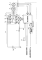
- FIG. 1 is a diagram illustrating a configuration example of a motor drive circuit according to the first embodiment.
- FIG. 2 is a diagram illustrating a configuration example of the voltage control unit.
- FIG. 3 is a diagram illustrating an example of input / output timing of the voltage control unit.
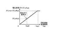
- FIG. 4 is a diagram illustrating the relationship between the rotation speed control signal and the voltage output.
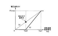
- FIG. 5 is a diagram showing the relationship between the rotation speed control signal and the voltage advance angle.
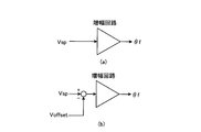
- FIG. 6 is a diagram showing a schematic configuration of the voltage advance signal generation circuit.
- FIG. 7 is a diagram showing an outline of the operation of the voltage advance signal generation circuit.
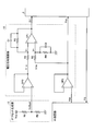
- FIG. 8 is a diagram illustrating a circuit configuration example of the voltage phase adjustment unit and the offset generation unit according to the first embodiment.
- FIG. 8 is a diagram illustrating a circuit configuration example of the voltage phase adjustment unit and the offset generation unit according to the first embodiment.
- FIG. 9 is a diagram showing the relationship between the current and loss of the IGBT and MOSFET.
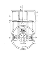
- FIG. 10 is a diagram illustrating an example in which a motor drive circuit and a permanent magnet synchronous motor are integrated.
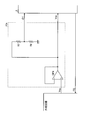
- FIG. 11 is a diagram illustrating a configuration example of a motor drive circuit according to the second embodiment.
- FIG. 12 is a diagram illustrating a circuit configuration example of the voltage phase adjustment unit according to the second embodiment.
- FIG. 13 is a diagram illustrating an arrangement of the magnetic pole position detection unit according to the second embodiment.
- FIG. 14 is a diagram illustrating an example of input / output timings of the voltage control unit according to the second embodiment.
- FIG. 15 is a diagram illustrating a relationship between the rotation speed control signal and the voltage advance angle according to the second embodiment.
- FIG. 1 is a diagram illustrating a configuration example of a motor drive circuit according to the first embodiment.
- the motor drive circuit 1 according to the present embodiment is a circuit that generates a drive voltage for the permanent magnet synchronous motor 7 based on a DC voltage Vdc supplied from a DC power supply 2.
- the motor drive circuit 1 mainly includes a voltage output unit 3 that operates as a voltage conversion unit, a voltage control unit 5, a magnetic pole position detection unit 11 that operates as a rotation position detection unit, and a voltage that operates as a voltage phase determination unit.
- a phase adjustment unit 12 and an offset generation unit 13 are provided.
- the voltage output unit 3 is electrically connected to the DC power source 2 through the shunt resistor 4, and based on a PWM (Pulse Width Modulation) signal sent from the voltage control unit 5, a freewheeling diode and a switching element are connected in parallel.
- the open / close sections 6a to 6f are driven to generate a voltage to be applied to the stator 8 constituting the permanent magnet synchronous motor 7. That is, a rotating magnetic field is generated by applying a voltage to the windings of the stator (stator) 8, and the rotor (rotor) 9 is driven to rotate.
- the voltage control unit 5 is driven by the control power supply 10 and is based on the outputs Hu, Hv, Hw of the magnetic pole position detection unit 11, the output ⁇ f of the voltage phase adjustment unit 12, and the DC current Idc detected by the shunt resistor 4.
- a PWM signal and a rotation speed signal FG for driving the open / close sections 6a to 6f of the voltage output section 3 are generated and output.
- the outputs Hu, Hv, and Hw of the magnetic pole position detector 11 are signals that vary according to the position (magnetic pole position) of the rotor 9 of the permanent magnet synchronous motor 7.
- the magnetic pole position detection unit 11 is constituted by a magnetic sensor, for example, and changes each output value (Hu, Hv, Hw) according to the measurement result of the magnetic field.
- the details of the magnetic pole position detector 11 are not particularly specified. Any known configuration and magnetic pole position detection method may be applied.
- the voltage phase adjustment unit 12 generates and outputs a voltage phase (voltage advance angle) ⁇ f based on the rotation speed control signal Vsp and the output Voffset of the offset generation unit 13.
- FIG. 2 is a diagram illustrating a configuration example of the voltage control unit 5.
- the voltage control unit 5 estimates the magnetic pole position based on the outputs Hu, Hv, and Hw of the magnetic pole position detection unit 11 and generates a rotational speed signal FG, and an estimation result obtained by the position estimation unit 14.
- a waveform generator 15 that generates waveform outputs Vu *, Vv *, and Vw * corresponding to the U phase, V phase, and W phase as modulated waves, and a triangular wave
- the triangular wave generation unit 16 that generates as a carrier wave, the waveform outputs Vu *, Vv *, and Vw * generated by the waveform generation unit 15 and the triangular wave generated by the triangular wave generation unit 16 are compared to High or corresponding to each UVW phase.
- the comparison unit 17 that outputs a Low signal and the signal output from the comparison unit 17 are received and a signal (inverted signal) obtained by inverting High and Low of each received signal is generated.
- the inverting unit 18 that is output together with each signal (non-inverted signal) received from the comparison unit 17, and the non-inverted signal and the inverted signal are input to the voltage output unit 3 with respect to the input signal (initial PWM signal).
- a dead time setting unit 19 for setting a dead time so that the upper and lower sides (6a and 6d, 6b and 6e, 6c and 6f) of the inner opening / closing units 6a to 6f are not turned on at the same time.
- This voltage control unit 5 uses the PWM signal (UP) for controlling the voltage output unit 3 (each open / close unit forming the voltage output unit 3) as a signal after the dead time is set by the dead time setting unit 19. , VP, WP, UN, VN, WN), and the open / close sections 6a to 6f of the voltage output section 3 are operated to drive the permanent magnet synchronous motor 7.
- FIG. 3 is a diagram illustrating an example of input / output timing of the voltage control unit 5.
- the magnetic pole position detection unit 11 As the rotor 9 of the permanent magnet synchronous motor 7 rotates, the magnetic pole position detection unit 11 generates UVW phase position signals Hu, Hv, and Hw.
- the rising zero cross of the substantially sinusoidal U-phase waveform output Vu * is located at a position where the phase of the voltage phase ⁇ f has advanced with reference to the falling edge of Hu.
- V-phase and W-phase waveform outputs Vv * and Vw * having a phase difference of ⁇ 120 ° are generated.
- the generated waveform outputs Vu *, Vv *, Vw * are compared with a triangular wave (triangular wave generated by the triangular wave generating unit 16). For example, when Vu * is larger than the triangular wave, UP is High and UN is Low. To do. V phase and W phase are obtained similarly.
- the waveform outputs Vu *, Vv *, and Vw * are substantially sine waves.
- the waveform outputs Vu *, Vv *, and Vw * are generally used for a method of superimposing third-order harmonics and motor control such as space vector modulation and two-phase modulation. It goes without saying that there is no problem using the method.
- the voltage control unit 5 operates based on the rotational speed control signal Vsp, the voltage advance angle ⁇ f, and the position signals Hu, Hv, and Hw, but whether or not the permanent magnet synchronous motor 7 is driven is performed only by Vsp,
- the voltage output from the voltage output unit 3 is started, and the permanent magnet synchronous motor 7 is driven.
- Vsp the permanent magnet synchronous motor 7 actually starts driving.
- Vsp exceeds Vsp0
- the rotor 9 of the permanent magnet synchronous motor 7 starts rotating, and the value of the rotational speed signal FG output from the position estimating unit 14 varies.
- a circuit (not shown) that generates Vsp calculates the rotation speed of the rotor 9 based on the rotation speed signal FG, and controls to increase or decrease Vsp according to the difference between the calculated rotation speed and the target rotation speed.
- the rotational speed can be stably operated in the vicinity of the target value rotational speed.
- FIG. 5 shows the optimum relationship between the rotational speed control signal Vsp and the voltage advance angle ⁇ f in a device whose load increases according to the rotational speed.
- FIGS. 6 and 7 are diagrams showing a configuration outline and an operation outline of the voltage phase adjustment unit 12 (referred to herein as a “voltage advance signal generation circuit” for convenience of explanation) according to the related art and the present embodiment.
- 6A shows an overview of a conventional voltage advance signal generation circuit
- FIG. 6B shows an overview of the voltage advance signal generation circuit (voltage phase adjustment unit 12) of the present embodiment.
- FIG. 7 shows the operation of generating the voltage advance signal ( ⁇ f), where (a) shows the conventional operation and (b) shows the operation of the present embodiment.
- FIG. 8 is a diagram illustrating a circuit configuration example of the voltage phase adjustment unit 12 and the offset generation unit 13 according to the first embodiment.
- the voltage phase adjustment unit 12 includes an operational amplifier circuit including an operational amplifier OP1, resistors R1 to R4, and capacitors C1 and C2.
- voltage follower circuits composed of operational amplifiers OP2 and OP3 are connected to the two input terminals (V + in, V-in) of the differential amplifier circuit, respectively, so as to reduce the influence of the impedance at the connection destination.
- Vsp is input to the V + in terminal through a voltage follower circuit based on OP3.
- the offset generator 13 is connected to the V-in terminal via a voltage follower circuit based on OP2.
- the operation amplification circuit of the voltage phase adjustment unit 12 amplifies the difference between the V + in terminal and the V ⁇ in terminal by a magnification determined by the resistance values of the resistors R1 to R4, and outputs the amplified voltage as the voltage advance angle ⁇ f.
- the offset generation unit 13 is configured to divide and output the control power supply 10 (Vcc) by the resistors R5 and R6, and can generate the offset inexpensively with the minimum necessary configuration. When it is desired to control the voltage advance angle ⁇ f with high accuracy, the offset accuracy is required. Therefore, the offset may be generated using a device such as a shunt regulator.
- the voltage phase adjuster 12 shown in FIG. 8 uses voltage followers by the operational amplifiers OP2 and OP3 in order to reduce the influence of the impedance. However, when the influence of the impedance is small, these are omitted to reduce the cost. You may make it show.
- the cutoff frequency of the low-pass filter by R3 and R4 connected in parallel is set below the frequency of the permanent magnet synchronous motor. This is provided to stabilize the rotational speed.
- the value of the voltage phase ⁇ f is not determined and the maximum efficiency operation cannot be performed.
- the voltage advance angle ⁇ f is increased too much, the permanent magnet synchronous motor 7 is weakened and the magnetic flux operation is performed, and the voltage required for rotation is reduced. The rotational speed of 7 increases.
- the motor drive circuit 1 and the permanent magnet synchronous motor 7 may be destroyed. Therefore, a mechanism (not shown) for limiting one or both of the lower limit and the upper limit of the voltage advance angle ⁇ f output from the voltage phase adjustment unit 12 may be provided. As a result, it is possible to prevent the motor drive circuit 1 and the permanent magnet synchronous motor 7 from being destroyed, and the reliability can be improved.
- the above-described limitation of the voltage advance angle ⁇ f is often accompanied by a built-in function in the IC constituting the voltage control unit 5 in recent years as the performance of the IC has been improved.
- the function installed in the circuit it is possible to limit the voltage advance angle ⁇ f without preparing a special circuit outside, so that not only the reliability can be improved but also the cost can be reduced. It becomes possible.
- the voltage advance angle ⁇ f that specifies the relationship between the triangular wave as the carrier wave and the waveform (Vu *, Vv *, Vw *) to be compared with the triangular wave is generated.
- the voltage phase adjustment unit 12 to generate the voltage advance angle ⁇ f based on the rotation speed control signal (Vsp) and the offset value (Voffset) generated by the offset generation unit 13, and the offset generation unit 13 Until the output unit 3 starts the voltage applied to the permanent magnet synchronous motor 7, that is, until the value of the rotation speed control signal (Vsp) reaches the drive start point (Vsp0) of the permanent magnet synchronous motor 7.
- the switching elements constituting the open / close sections 6a to 6f can be changed from IGBT (Insulated Gate Bipolar Transistor) to MOSFET (Metal-Oxide-Semiconductor Field-Effect Transistor). .
- IGBT Insulated Gate Bipolar Transistor
- MOSFET Metal-Oxide-Semiconductor Field-Effect Transistor
- FIG. 9 since the MOSFET operates with low loss in the low current region, energy saving (high efficiency) can be achieved by forming the open / close sections 6a to 6f with MOSFET.
- the overall design of the device can be reduced by downsizing the radiating fins.
- the free wheeling diode constituting the open / close sections 6a to 6f may be a wide band gap semiconductor. Note that a loss improvement effect can be obtained by using a MOSFET or a wide band gap semiconductor for a part (at least one) of the open / close parts 6a to 6f.
- the voltage phase adjustment unit 12 continuously increases the voltage advance angle ⁇ f according to the rotational speed, the optimum voltage advance angle is applied to, for example, a blower fan whose load increases according to the rotational speed. Therefore, it is possible to reduce noise at a low rotation speed.
- the current flowing through the permanent magnet synchronous motor 7 and the voltage output unit 3 can be reduced during high-speed rotation, not only the above-described effects can be obtained, but also a rapid change in the voltage advance angle can be prevented. As a result, the rotational speed of the blower fan can be stably controlled, and the reliability can be improved.
- the reliability is improved while being less susceptible to the influence of dust and water, and the permanent magnet synchronous motor.
- the dielectric strength of 7 is improved.
- heat is severe because a large current flows through the motor drive circuit 1 and the permanent magnet synchronous motor 7.
- the heat capacity increases, it is difficult for heat to be generated, and it is possible to prevent thermal destruction of the motor drive circuit 1 due to heat generation.
- FIG. FIG. 11 is a diagram illustrating a configuration example of a motor drive circuit according to the second embodiment.
- the offset generation unit 13 is deleted from the motor drive circuit 1 of the first embodiment, and the voltage phase adjustment unit 12 is replaced with a voltage phase adjustment unit 12a.
- Other than these components are the same as those in the first embodiment, so the same reference numerals are given and the description thereof is omitted.
- FIG. 12 is a diagram illustrating a circuit configuration example of the voltage phase adjustment unit 12a according to the second embodiment.
- the voltage phase adjustment unit 12a includes an operational amplifier OP4 and resistors R7 and R8.
- a rotation speed control signal Vsp generated from an external circuit is connected to the voltage control unit 5 and the resistors R7 and R7 via a voltage follower circuit using the operational amplifier OP4. It is input to the voltage dividing circuit composed of R8.
- the voltage dividing circuit multiplies the input rotational speed control signal Vsp by R8 / (R7 + R8), and outputs the resulting value to the voltage control unit 5 as the voltage advance angle ⁇ f.
- the voltage advance angle ⁇ f is generated only by multiplying Vsp by R8 / (R7 + R8) by the voltage dividing circuit, similarly to the control by the conventional method shown in FIG. As a result, the voltage advance angle ⁇ f becomes excessive, and there is a concern that heat generation and noise increase due to an increase in current. Therefore, in the present embodiment, it is assumed that the attachment position of the magnetic pole position detection unit 11 is rotated about the shaft 21 as shown in FIG. That is, the magnetic pole position detector 11 is attached at a position different from that of the first embodiment (see FIG. 10).
- the same effects as those of the first embodiment described above can be obtained. Further, the number of parts of the voltage phase adjustment unit 12a can be reduced as compared with the voltage phase adjustment unit 12 of the first embodiment, and the magnetic pole position detection unit 11 only changes the mounting position, so that the motor drive circuit is reduced. This can be realized at a low cost. Furthermore, it is possible to reduce the number of parts and ensure reliability.
- the motor drive circuit according to the present invention is useful when driving a permanent magnet synchronous motor, and in particular, an outdoor unit of an air conditioner or a heat pump water heater, a fan motor of an indoor unit, and a ventilation fan. It is suitable for a motor drive circuit that drives a fan motor or the like.
Abstract
Description
図1は、実施の形態1のモータ駆動回路の構成例を示す図である。本実施の形態のモータ駆動回路1は、直流電源2から供給される直流電圧Vdcに基づいて永久磁石同期モータ7の駆動電圧を生成する回路である。モータ駆動回路1は、主たる構成として、電圧変換手段として動作する電圧出力部3と、電圧制御部5と、回転位置検出手段として動作する磁極位置検出部11と、電圧位相決定手段として動作する電圧位相調整部12と、オフセット生成部13とを備えている。
FIG. 1 is a diagram illustrating a configuration example of a motor drive circuit according to the first embodiment. The
図11は、実施の形態2のモータ駆動回路の構成例を示す図である。本実施の形態のモータ駆動回路1aは、実施の形態1のモータ駆動回路1からオフセット生成部13を削除するとともに、電圧位相調整部12を電圧位相調整部12aに置き換えたものである。これらの構成要素以外については実施の形態1と同様であるため、同一の符号を付して説明を省略する。
FIG. 11 is a diagram illustrating a configuration example of a motor drive circuit according to the second embodiment. In the
2 直流電源
3 電圧出力部
4 シャント抵抗
5 電圧制御部
6a,6b,6c,6d,6e,6f 開閉部
7 永久磁石同期モータ
8 ステータ
9 ロータ
10 制御電源
11 磁極位置検出部
12,12a 電圧位相調整部
13 オフセット生成部
14 位置推定部
15 波形出力生成部
16 三角波生成部
17 比較部
18 反転部
19 デットタイム設定部
20 モールド樹脂
21 シャフト DESCRIPTION OF
Claims (10)
- 永久磁石同期モータの回転子の回転位置を検出する回転位置検出手段と、
直流電圧を変換して前記永久磁石同期モータの駆動電圧を生成する電圧変換手段と、
前記回転位置と、前記回転子の回転速度を制御する回転速度制御信号とに基づいて変調波を生成し、当該変調波と搬送波の比較結果に基づいて、前記電圧変換手段を制御する電圧制御手段と、
前記回転速度制御信号およびオフセット信号に基づいて前記電圧制御手段が生成する変調波の位相を決定し、当該決定した位相で前記電圧制御手段に変調波を生成させる電圧位相決定手段と、
前記オフセット信号を生成するオフセット生成手段と、
を備え、
前記電圧位相決定手段は、前記回転速度制御信号および前記オフセット信号を入力とする差動増幅回路によって前記位相を決定することを特徴とするモータ駆動回路。 Rotational position detecting means for detecting the rotational position of the rotor of the permanent magnet synchronous motor;
Voltage converting means for converting a DC voltage to generate a driving voltage for the permanent magnet synchronous motor;
Voltage control means for generating a modulation wave based on the rotation position and a rotation speed control signal for controlling the rotation speed of the rotor and for controlling the voltage conversion means based on a comparison result between the modulation wave and a carrier wave When,
A voltage phase determining means for determining a phase of a modulation wave generated by the voltage control means based on the rotation speed control signal and an offset signal, and causing the voltage control means to generate a modulation wave at the determined phase;
Offset generating means for generating the offset signal;
With
The motor drive circuit according to claim 1, wherein the voltage phase determination means determines the phase by a differential amplifier circuit that receives the rotation speed control signal and the offset signal. - 前記オフセット生成手段は、前記回転子が回転していない状態において前記位相が0°となるオフセット値を示すオフセット信号を生成することを特徴とする請求項1に記載のモータ駆動回路。 The motor drive circuit according to claim 1, wherein the offset generation means generates an offset signal indicating an offset value at which the phase is 0 ° in a state where the rotor is not rotating.
- 前記オフセット信号が示すオフセット値は、前記回転子が回転を開始する際の回転速度制御信号の値であることを特徴とする請求項1または2に記載のモータ駆動回路。 3. The motor drive circuit according to claim 1, wherein the offset value indicated by the offset signal is a value of a rotation speed control signal when the rotor starts rotating.
- 前記オフセット生成手段は、少なくとも2つ以上の抵抗からなる分圧回路によって前記オフセット信号を生成することを特徴とする請求項1、2または3に記載のモータ駆動回路。 The motor drive circuit according to claim 1, 2 or 3, wherein the offset generation means generates the offset signal by a voltage dividing circuit composed of at least two resistors.
- 永久磁石同期モータの回転子の回転位置を検出する回転位置検出手段と、
直流電圧を変換して前記永久磁石同期モータの駆動電圧を生成する電圧変換手段と、
前記回転位置と、前記回転子の回転速度を制御する回転速度制御信号とに基づいて変調波を生成し、当該変調波と搬送波の比較結果に基づいて、前記電圧変換手段を制御する電圧制御手段と、
前記回転速度制御信号に基づいて前記電圧制御手段が生成する変調波の位相を決定し、当該決定した位相で前記電圧制御手段に変調波を生成させる電圧位相決定手段と、
を備え、
前記回転速度制御信号は前記回転位置に基づいて算出される前記回転子の回転速度に応じて値が変化する信号であり、
前記回転位置検出手段と前記永久磁石同期モータの固定子の位置関係は、前記回転子が回転を開始する時点における前記電圧位相決定手段の決定位相が0°となる関係であることを特徴とするモータ駆動回路。 Rotational position detecting means for detecting the rotational position of the rotor of the permanent magnet synchronous motor;
Voltage converting means for converting a DC voltage to generate a driving voltage for the permanent magnet synchronous motor;
Voltage control means for generating a modulation wave based on the rotation position and a rotation speed control signal for controlling the rotation speed of the rotor and for controlling the voltage conversion means based on a comparison result between the modulation wave and a carrier wave When,
Determining a phase of a modulated wave generated by the voltage control unit based on the rotation speed control signal, and causing the voltage control unit to generate a modulated wave with the determined phase; and
With
The rotational speed control signal is a signal whose value changes according to the rotational speed of the rotor calculated based on the rotational position;
The positional relationship between the rotational position detecting means and the stator of the permanent magnet synchronous motor is such that the determined phase of the voltage phase determining means is 0 ° when the rotor starts rotating. Motor drive circuit. - 電圧位相決定手段は、決定する位相の上限および下限の少なくとも一方を設定することを特徴とする請求項1~5のいずれか一つに記載のモータ駆動回路。 6. The motor drive circuit according to claim 1, wherein the voltage phase determining means sets at least one of an upper limit and a lower limit of the phase to be determined.
- 前記電圧変換手段を構成しているスイッチング素子のうち、少なくとも1つがMOSFETで形成されていることを特徴とする請求項1~6のいずれか一つに記載のモータ駆動回路。 The motor drive circuit according to any one of claims 1 to 6, wherein at least one of the switching elements constituting the voltage conversion means is formed of a MOSFET.
- 前記電圧変換手段を構成しているスイッチング素子及び環流ダイオードのうち、少なくとも1つがワイドバンドギャップ半導体で形成されていることを特徴とする請求項1~6のいずれか一つに記載のモータ駆動回路。 The motor drive circuit according to any one of claims 1 to 6, wherein at least one of the switching element and the freewheeling diode constituting the voltage conversion means is formed of a wide band gap semiconductor. .
- 前記ワイドバンドギャップ半導体は、炭化珪素、窒化ガリウム系材料又はダイヤモンドであることを特徴とする請求項8に記載のモータ駆動回路。 9. The motor drive circuit according to claim 8, wherein the wide band gap semiconductor is silicon carbide, a gallium nitride-based material, or diamond.
- 請求項1~9のいずれか一つに記載のモータ駆動回路により駆動されることを特徴とする永久磁石同期モータ。 A permanent magnet synchronous motor driven by the motor drive circuit according to any one of claims 1 to 9.
Priority Applications (5)
| Application Number | Priority Date | Filing Date | Title |
|---|---|---|---|
| JP2013555081A JP5797781B2 (en) | 2012-01-27 | 2012-01-27 | Motor drive circuit and permanent magnet synchronous motor |
| US14/369,733 US9231507B2 (en) | 2012-01-27 | 2012-01-27 | Motor driving curcuit and permanent magnet synchronous motor |
| EP12866656.7A EP2808997B1 (en) | 2012-01-27 | 2012-01-27 | Motor driving circuit and permanent magnet synchronous motor |
| PCT/JP2012/051827 WO2013111326A1 (en) | 2012-01-27 | 2012-01-27 | Motor drive circuit and permanent magnet synchronous motor |
| CN201280067341.XA CN104054258B (en) | 2012-01-27 | 2012-01-27 | Motor drive circuit and permanent magnet synchronous motor |
Applications Claiming Priority (1)
| Application Number | Priority Date | Filing Date | Title |
|---|---|---|---|
| PCT/JP2012/051827 WO2013111326A1 (en) | 2012-01-27 | 2012-01-27 | Motor drive circuit and permanent magnet synchronous motor |
Publications (1)
| Publication Number | Publication Date |
|---|---|
| WO2013111326A1 true WO2013111326A1 (en) | 2013-08-01 |
Family
ID=48873089
Family Applications (1)
| Application Number | Title | Priority Date | Filing Date |
|---|---|---|---|
| PCT/JP2012/051827 WO2013111326A1 (en) | 2012-01-27 | 2012-01-27 | Motor drive circuit and permanent magnet synchronous motor |
Country Status (5)
| Country | Link |
|---|---|
| US (1) | US9231507B2 (en) |
| EP (1) | EP2808997B1 (en) |
| JP (1) | JP5797781B2 (en) |
| CN (1) | CN104054258B (en) |
| WO (1) | WO2013111326A1 (en) |
Cited By (1)
| Publication number | Priority date | Publication date | Assignee | Title |
|---|---|---|---|---|
| CN113581233A (en) * | 2021-07-23 | 2021-11-02 | 石家庄国祥运输设备有限公司 | Control method of air-conditioning ventilator of railway vehicle |
Families Citing this family (10)
| Publication number | Priority date | Publication date | Assignee | Title |
|---|---|---|---|---|
| WO2012086010A1 (en) * | 2010-12-21 | 2012-06-28 | 三菱電機株式会社 | Heat pump device, heat pump system, and method for controlling three-phase inverter |
| JP6324919B2 (en) * | 2015-03-17 | 2018-05-16 | ミネベアミツミ株式会社 | Motor drive control device and control method thereof |
| JP6329504B2 (en) * | 2015-03-17 | 2018-05-23 | ミネベアミツミ株式会社 | Motor drive control device and motor drive control method |
| JP6296566B2 (en) * | 2015-11-27 | 2018-03-20 | ミネベアミツミ株式会社 | Motor drive control device |
| JP6374857B2 (en) * | 2015-11-27 | 2018-08-15 | ミネベアミツミ株式会社 | Motor drive control device |
| DE102016221459A1 (en) * | 2016-11-02 | 2018-05-03 | Robert Bosch Gmbh | Method for determining a rotational angle position of a crankshaft of an internal combustion engine |
| TW201910645A (en) * | 2017-07-26 | 2019-03-16 | 茂達電子股份有限公司 | Fan control circuit and fan control method |
| CN108809165A (en) * | 2018-06-29 | 2018-11-13 | 广东水利电力职业技术学院(广东省水利电力技工学校) | A kind of AC servo driver system and control method |
| WO2020033534A1 (en) | 2018-08-08 | 2020-02-13 | Graphaudio | High volume manufacturing of micro electrostatic transducers |
| JP7163223B2 (en) * | 2019-03-14 | 2022-10-31 | 株式会社東芝 | Driving device, driving system, and driving method for electric motor |
Citations (5)
| Publication number | Priority date | Publication date | Assignee | Title |
|---|---|---|---|---|
| JP2003189666A (en) * | 2001-12-11 | 2003-07-04 | Nidec Shibaura Corp | Brushless dc motor |
| JP2007275827A (en) * | 2006-04-10 | 2007-10-25 | Tsubaki Emerson Co | Control method for brushless dc motor of shredder and controller for brushless dc motor of shredder |
| JP2009303287A (en) | 2008-06-10 | 2009-12-24 | Nidec Shibaura Corp | Motor controller |
| JP2011114995A (en) | 2009-11-30 | 2011-06-09 | Nidec Shibaura Corp | Drive circuit for motor and motor equipped with the same |
| WO2011111262A1 (en) * | 2010-03-09 | 2011-09-15 | 三菱電機株式会社 | Power semiconductor module, electric power converter, and railway vehicle |
Family Cites Families (17)
| Publication number | Priority date | Publication date | Assignee | Title |
|---|---|---|---|---|
| US4546293A (en) * | 1982-08-24 | 1985-10-08 | Sundstrand Corporation | Motor control for a brushless DC motor |
| JP3360934B2 (en) | 1994-06-07 | 2003-01-07 | 株式会社日立製作所 | Energizing phase angle control device for brushless motor |
| DE10037972B4 (en) * | 1999-08-05 | 2005-09-15 | Sharp K.K. | Device and method for electric motor control |
| US6222333B1 (en) * | 1999-12-10 | 2001-04-24 | Texas Instruments Incorporated | DC brushless motor controller apparatus and method |
| JP3442024B2 (en) * | 2000-02-29 | 2003-09-02 | 株式会社日立製作所 | Motor driving circuit, motor driving method, and semiconductor integrated circuit device |
| JP2002101683A (en) | 2000-09-26 | 2002-04-05 | Nidec Shibaura Corp | Phase angle control method of brushless dc motor |
| US6694287B2 (en) * | 2001-08-30 | 2004-02-17 | Delphi Technologies, Inc. | Phase angle diagnostics for sinusoidal controlled electric machine |
| WO2003029503A2 (en) * | 2001-10-01 | 2003-04-10 | Delphi Technologies, Inc. | Method and apparatus for calibrating and initializing an electronically commutated electric machine |
| JP2003324985A (en) | 2002-04-26 | 2003-11-14 | Toyoda Mach Works Ltd | Motor controller |
| JP2004180399A (en) * | 2002-11-26 | 2004-06-24 | Murata Mach Ltd | Method of driving motor in thread winder |
| JP4671331B2 (en) | 2004-02-25 | 2011-04-13 | ローム株式会社 | Phase adjustment circuit, motor drive control circuit, and motor device |
| JP4422567B2 (en) * | 2004-06-30 | 2010-02-24 | 株式会社日立製作所 | Motor drive device, electric actuator, and electric power steering device |
| US7075267B1 (en) * | 2004-12-29 | 2006-07-11 | Prolific Technology Inc. | Space vector-based current controlled PWM inverter for motor drives |
| JP2008005632A (en) * | 2006-06-22 | 2008-01-10 | Matsushita Electric Ind Co Ltd | Motor drive device, motor drive method and disk drive device |
| CN101615876B (en) * | 2009-08-07 | 2011-07-27 | 北京和利时电机技术有限公司 | Timing control system and method for non-salient pole permanent magnet synchronous motor |
| JP2011045217A (en) * | 2009-08-24 | 2011-03-03 | Ricoh Co Ltd | Brushless motor drive |
| JP5484926B2 (en) * | 2010-01-18 | 2014-05-07 | 三菱重工業株式会社 | Insulation deterioration detector and in-vehicle high voltage system |
-
2012
- 2012-01-27 US US14/369,733 patent/US9231507B2/en not_active Expired - Fee Related
- 2012-01-27 WO PCT/JP2012/051827 patent/WO2013111326A1/en active Application Filing
- 2012-01-27 EP EP12866656.7A patent/EP2808997B1/en active Active
- 2012-01-27 JP JP2013555081A patent/JP5797781B2/en active Active
- 2012-01-27 CN CN201280067341.XA patent/CN104054258B/en not_active Expired - Fee Related
Patent Citations (5)
| Publication number | Priority date | Publication date | Assignee | Title |
|---|---|---|---|---|
| JP2003189666A (en) * | 2001-12-11 | 2003-07-04 | Nidec Shibaura Corp | Brushless dc motor |
| JP2007275827A (en) * | 2006-04-10 | 2007-10-25 | Tsubaki Emerson Co | Control method for brushless dc motor of shredder and controller for brushless dc motor of shredder |
| JP2009303287A (en) | 2008-06-10 | 2009-12-24 | Nidec Shibaura Corp | Motor controller |
| JP2011114995A (en) | 2009-11-30 | 2011-06-09 | Nidec Shibaura Corp | Drive circuit for motor and motor equipped with the same |
| WO2011111262A1 (en) * | 2010-03-09 | 2011-09-15 | 三菱電機株式会社 | Power semiconductor module, electric power converter, and railway vehicle |
Non-Patent Citations (1)
| Title |
|---|
| See also references of EP2808997A4 |
Cited By (1)
| Publication number | Priority date | Publication date | Assignee | Title |
|---|---|---|---|---|
| CN113581233A (en) * | 2021-07-23 | 2021-11-02 | 石家庄国祥运输设备有限公司 | Control method of air-conditioning ventilator of railway vehicle |
Also Published As
| Publication number | Publication date |
|---|---|
| US9231507B2 (en) | 2016-01-05 |
| EP2808997A4 (en) | 2016-03-23 |
| CN104054258A (en) | 2014-09-17 |
| JPWO2013111326A1 (en) | 2015-05-11 |
| EP2808997B1 (en) | 2017-11-29 |
| US20150002061A1 (en) | 2015-01-01 |
| EP2808997A1 (en) | 2014-12-03 |
| JP5797781B2 (en) | 2015-10-21 |
| CN104054258B (en) | 2016-09-28 |
Similar Documents
| Publication | Publication Date | Title |
|---|---|---|
| JP5797781B2 (en) | Motor drive circuit and permanent magnet synchronous motor | |
| JP6067105B2 (en) | Power conversion apparatus, motor drive apparatus including the same, blower including the same, compressor, air conditioner including them, refrigerator, and refrigerator | |
| KR101474263B1 (en) | Motor control device, and air-conditioner using the same | |
| JP2006296194A (en) | Sensorless and brushless dc motor drive using speed control by pulse width modulation at motor frequency | |
| JP6644159B2 (en) | Motor drive, electric blower, vacuum cleaner and hand dryer | |
| WO2013080610A1 (en) | Power converter, electric motor drive device, and air conditioner | |
| US11165381B2 (en) | Speed contant control and power constant control of a permanent magnet synchronous motor | |
| TW201526523A (en) | Driving device and driving method for motor, cooling device and electronic machine | |
| WO2018138807A1 (en) | Motor drive device, electric fan, electric cleaner, and hand dryer | |
| WO2018047274A1 (en) | Motor drive device, electric fan, and electric vacuum cleaner | |
| JP6800329B2 (en) | Motor drive, electric blower, vacuum cleaner and hand dryer | |
| US11316465B2 (en) | Motor drive device, electric blower, electric vacuum cleaner, and hand dryer | |
| EP3416280A1 (en) | Inverter apparatus, air conditioner, method of controlling inverter apparatus, and program | |
| JP6180578B1 (en) | Control device and control method for power conversion device | |
| JP2020074670A (en) | Motor driving device, electric blower, vacuum cleaner, and hand drier | |
| Lai et al. | Back-EMF detection technique of brushless DC motor drives for wide range control | |
| JP2008160915A (en) | Inverter controller for driving motor and apparatus employing the same | |
| WO2018055671A1 (en) | Inverter device, compressor drive device, and air conditioner | |
| JP4170479B2 (en) | DC motor current detection control device and electric apparatus equipped with the device | |
| CN110326210B (en) | Air conditioner | |
| US11557998B2 (en) | Open loop duty control with automatic field orientation for a permanent magnet AC (PMAC) motor | |
| JP7361798B2 (en) | heat pump equipment | |
| KR102612830B1 (en) | Power converting apparatus | |
| CN110620459B (en) | Driving circuit for operating BLDC motor | |
| US11863104B2 (en) | Motor drive device, electric blower, electric vacuum cleaner, and hand dryer |
Legal Events
| Date | Code | Title | Description |
|---|---|---|---|
| 121 | Ep: the epo has been informed by wipo that ep was designated in this application |
Ref document number: 12866656 Country of ref document: EP Kind code of ref document: A1 |
|
| ENP | Entry into the national phase |
Ref document number: 2013555081 Country of ref document: JP Kind code of ref document: A |
|
| WWE | Wipo information: entry into national phase |
Ref document number: 14369733 Country of ref document: US |
|
| NENP | Non-entry into the national phase |
Ref country code: DE |
|
| REEP | Request for entry into the european phase |
Ref document number: 2012866656 Country of ref document: EP |
|
| WWE | Wipo information: entry into national phase |
Ref document number: 2012866656 Country of ref document: EP |