WO2011111262A1 - Power semiconductor module, electric power converter, and railway vehicle - Google Patents
Power semiconductor module, electric power converter, and railway vehicle Download PDFInfo
- Publication number
- WO2011111262A1 WO2011111262A1 PCT/JP2010/069383 JP2010069383W WO2011111262A1 WO 2011111262 A1 WO2011111262 A1 WO 2011111262A1 JP 2010069383 W JP2010069383 W JP 2010069383W WO 2011111262 A1 WO2011111262 A1 WO 2011111262A1
- Authority
- WO
- WIPO (PCT)
- Prior art keywords
- conducting
- band gap
- voltage
- temperature coefficient
- parallel
- Prior art date
Links
Images


Classifications
-
- H—ELECTRICITY
- H02—GENERATION; CONVERSION OR DISTRIBUTION OF ELECTRIC POWER
- H02M—APPARATUS FOR CONVERSION BETWEEN AC AND AC, BETWEEN AC AND DC, OR BETWEEN DC AND DC, AND FOR USE WITH MAINS OR SIMILAR POWER SUPPLY SYSTEMS; CONVERSION OF DC OR AC INPUT POWER INTO SURGE OUTPUT POWER; CONTROL OR REGULATION THEREOF
- H02M5/00—Conversion of ac power input into ac power output, e.g. for change of voltage, for change of frequency, for change of number of phases
- H02M5/40—Conversion of ac power input into ac power output, e.g. for change of voltage, for change of frequency, for change of number of phases with intermediate conversion into dc
- H02M5/42—Conversion of ac power input into ac power output, e.g. for change of voltage, for change of frequency, for change of number of phases with intermediate conversion into dc by static converters
- H02M5/44—Conversion of ac power input into ac power output, e.g. for change of voltage, for change of frequency, for change of number of phases with intermediate conversion into dc by static converters using discharge tubes or semiconductor devices to convert the intermediate dc into ac
- H02M5/453—Conversion of ac power input into ac power output, e.g. for change of voltage, for change of frequency, for change of number of phases with intermediate conversion into dc by static converters using discharge tubes or semiconductor devices to convert the intermediate dc into ac using devices of a triode or transistor type requiring continuous application of a control signal
- H02M5/458—Conversion of ac power input into ac power output, e.g. for change of voltage, for change of frequency, for change of number of phases with intermediate conversion into dc by static converters using discharge tubes or semiconductor devices to convert the intermediate dc into ac using devices of a triode or transistor type requiring continuous application of a control signal using semiconductor devices only
- H02M5/4585—Conversion of ac power input into ac power output, e.g. for change of voltage, for change of frequency, for change of number of phases with intermediate conversion into dc by static converters using discharge tubes or semiconductor devices to convert the intermediate dc into ac using devices of a triode or transistor type requiring continuous application of a control signal using semiconductor devices only having a rectifier with controlled elements
-
- B—PERFORMING OPERATIONS; TRANSPORTING
- B60—VEHICLES IN GENERAL
- B60L—PROPULSION OF ELECTRICALLY-PROPELLED VEHICLES; SUPPLYING ELECTRIC POWER FOR AUXILIARY EQUIPMENT OF ELECTRICALLY-PROPELLED VEHICLES; ELECTRODYNAMIC BRAKE SYSTEMS FOR VEHICLES IN GENERAL; MAGNETIC SUSPENSION OR LEVITATION FOR VEHICLES; MONITORING OPERATING VARIABLES OF ELECTRICALLY-PROPELLED VEHICLES; ELECTRIC SAFETY DEVICES FOR ELECTRICALLY-PROPELLED VEHICLES
- B60L9/00—Electric propulsion with power supply external to the vehicle
- B60L9/16—Electric propulsion with power supply external to the vehicle using ac induction motors
- B60L9/18—Electric propulsion with power supply external to the vehicle using ac induction motors fed from dc supply lines
- B60L9/22—Electric propulsion with power supply external to the vehicle using ac induction motors fed from dc supply lines polyphase motors
-
- H—ELECTRICITY
- H03—ELECTRONIC CIRCUITRY
- H03K—PULSE TECHNIQUE
- H03K17/00—Electronic switching or gating, i.e. not by contact-making and –breaking
- H03K17/12—Modifications for increasing the maximum permissible switched current
- H03K17/127—Modifications for increasing the maximum permissible switched current in composite switches
-
- B—PERFORMING OPERATIONS; TRANSPORTING
- B60—VEHICLES IN GENERAL
- B60L—PROPULSION OF ELECTRICALLY-PROPELLED VEHICLES; SUPPLYING ELECTRIC POWER FOR AUXILIARY EQUIPMENT OF ELECTRICALLY-PROPELLED VEHICLES; ELECTRODYNAMIC BRAKE SYSTEMS FOR VEHICLES IN GENERAL; MAGNETIC SUSPENSION OR LEVITATION FOR VEHICLES; MONITORING OPERATING VARIABLES OF ELECTRICALLY-PROPELLED VEHICLES; ELECTRIC SAFETY DEVICES FOR ELECTRICALLY-PROPELLED VEHICLES
- B60L2200/00—Type of vehicles
- B60L2200/26—Rail vehicles
Definitions
- the present invention relates to a power conversion device applicable to a railway vehicle, and more particularly to a power semiconductor module that can be mounted on this type of power conversion device.
- Patent Document 1 discloses an element pair in which a transistor chip and a fly wheel diode (FWD) chip are connected in antiparallel. Two power semiconductor modules are disclosed (see FIGS. 1 and 6 of the same document).
- the power semiconductor module there is a switching element (for example, IGBT) connected in reverse parallel to the FWD, and it is necessary to suppress the variation in the forward voltage characteristics to a certain value or less as well as the FWD. For this reason, in the conventional power semiconductor module in parallel application, there is a difficulty that both the switching element and the FWD have to be selected at the same time, and the yield for parallel operation is very large and the manufacturing cost is high. was there.
- a switching element for example, IGBT
- the present invention has been made in view of the above, and an object of the present invention is to provide a power semiconductor module that can improve the yield of power semiconductor modules in parallel applications and can suppress an increase in manufacturing cost.
- an object of this invention is to provide the power converter device provided with the above power semiconductor modules, and the rail vehicle provided with this power converter device.
- a power semiconductor module includes a first switching element and a first unidirectional conducting element having a negative temperature coefficient in voltage drop characteristics during conduction. And a first element pair in which a first conduction element having a positive temperature coefficient of voltage drop characteristic during conduction and a first conduction element connected in series are connected in antiparallel, and a second switching A second unidirectional conducting element having a negative temperature coefficient in the voltage drop characteristic during conduction and a second conducting element having a positive temperature coefficient in the voltage drop characteristic during conduction; And a second element pair connected in antiparallel, and the first and second element pairs are connected in parallel.
- FIG. 1 is a diagram illustrating a schematic functional configuration of a power conversion device according to an embodiment of the present invention.
- FIG. 2 is a diagram schematically showing a circuit configuration of the power semiconductor module according to the present embodiment.
- FIG. 3 is a diagram showing forward voltage characteristics of the Si diode.
- FIG. 4 is a diagram schematically showing a circuit configuration of a power semiconductor module according to the related art shown as a comparative example.
- FIG. 5 is a diagram showing forward voltage characteristics of the SiC diode.
- FIG. 6 is a comparative diagram showing a current simulation waveform when the IGBT in the switching element is turned on.
- FIG. 7 is a comparative diagram showing a simulation waveform of the FWD recovery current corresponding to FIG.
- FIG. 8 is a diagram showing the temperature dependence of the current-voltage characteristics in the linear region of the SiC-MOSFET.
- FIG. 9 is a schematic diagram regarding the turn-off current waveforms of the Si-IGBT and the SiC-
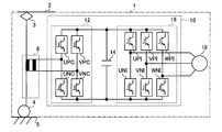
- FIG. 1 is a diagram illustrating a schematic functional configuration of the power conversion device according to the first embodiment, and illustrates a configuration example of the power conversion device 10 mounted on the railway vehicle 1.
- the power conversion device 10 includes a converter 12, a capacitor 14, and an inverter 16.
- the railway vehicle 1 includes a transformer 6 disposed on the input end side of the power conversion device 10 and connected to the converter 12, and disposed on the output end side of the power conversion device 10 and connected to the inverter 16.
- An electric motor 18 that drives the vehicle by receiving power supply from 10 is mounted.
- an induction motor or a synchronous motor is suitable.
- One end of the primary winding of the transformer 6 is connected to the overhead line 2 via the current collector 3, and the other end is connected to the rail 5 that is a ground potential via the wheel 4.
- the electric power supplied from the overhead line 2 is input to the primary winding of the transformer 6 through the current collector 3, and the electric power generated in the secondary winding of the transformer 6 is input to the converter 12.
- a positive arm composed of switching elements UPC and VPC (for example, UPC in U phase) and a negative arm composed of switching elements UNC and VNC (for example, UNC in U phase) are connected in series.
- Circuit portion (hereinafter referred to as “leg”). That is, the converter 12 includes a single-phase bridge circuit having two sets of legs (for U phase and V phase).
- the converter 12 converts the AC voltage input by PWM control of the switching elements UPC, VPC, UNC, and VNC into a desired DC voltage and outputs it.
- a capacitor 14 serving as a DC power source is connected in parallel to the output terminal of the converter 12, and an inverter 16 that receives the DC voltage of the capacitor 14 and converts it into an AC voltage having an arbitrary voltage and an arbitrary frequency and outputs it is connected. .
- the inverter 16 includes a positive side arm (for example, UPI in the U phase) configured by switching elements UPI, VPI, and WPI and a negative side arm (for example, UNI in the U phase) configured by switching elements UNI, VNI, and WNI. Each has a leg connected in series. That is, the inverter 16 includes a three-phase bridge circuit having three sets of legs (for U phase, V phase, and W phase).
- the inverter 16 converts the DC voltage input by PWM control of the switching elements UPI, VPI, WPI, UNI, VNI, WNI into a desired AC voltage and outputs it.
- FIG. 1 as a suitable example of the power conversion device according to the present embodiment, a case where it is applied to an AC electric vehicle is shown as an example, but a DC input frequently used in a subway, a suburban electric vehicle, or the like is shown. The same can be applied to an electric vehicle.
- a DC-input electric vehicle the configuration similar to that of FIG. 1 can be adopted except that the configurations of the transformer 6 and the converter 12 are not required. Of course, it can be applied to an input electric vehicle.
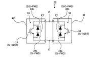
- FIG. 2 is a diagram schematically showing a circuit configuration of the power semiconductor module according to the present embodiment.
- the power semiconductor module 20 according to the present embodiment includes a first power module 22 and a second power module 32, and the first and second power modules 22 and 32. Are connected in parallel.
- the power semiconductor module 20 is the power conversion device shown in FIG. 1, for example, it can be applied to the switching elements UPC, VPC, UNC, VNC constituting the converter 12, or the switching element UPI constituting the inverter 16. , VPI, WPI, UNI, VNI, and WNI.
- Si-FWD FWD 24 a
- SiC-FWD FWD 24 b
- SiC silicon carbide
- IGBT 25 Si-IGBT
- the configuration of the second power module 32 is the same, and includes an FWD group 34 in which an Si-FWD (FWD 34a) and an SiC-FWD (FWD 34b) are connected in series, and the FWD group 34 connected in series,
- the Si-IGBT (IGBT 35) is connected in antiparallel to form the element pair 36.
- terminals drawn from one end of each of the element pairs 26 and 36 are connected to form a collector electrode C, and each other end of each of the element pairs 26 and 36 (of the Si-IGBT) Terminals drawn from each emitter end) are connected to form an emitter electrode E.
- FIG. 2 a configuration in which power modules in which one pair of elements in which switching elements and FWD groups are connected in antiparallel are accommodated in one module (so-called “1 in 1” configuration) is connected in parallel.
- a configuration in which one set of element pairs connected in parallel is accommodated in one module (a so-called “2 in 1” configuration) may be employed.
- FIG. 3 is a diagram showing forward voltage characteristics of the Si diode.
- FIG. 3 shows a change in forward current (so-called “on current”) with respect to a forward saturation voltage (so-called “on voltage”) using the junction temperature (Tj) of the PN junction in the Si diode as a parameter.
- FIG. 4 is a diagram schematically showing a circuit configuration of a power semiconductor module according to the related art shown as a comparative example.
- the temperature dependence of the forward saturation voltage in the Si diode has a characteristic that the forward saturation voltage decreases as the junction temperature increases as long as the forward current value is the same. . That is, the Si diode is an element having a negative temperature coefficient in the voltage drop characteristic during conduction.
- the FWD 54 when the forward saturation voltage of the Si-FWD (FWD 54) on the element pair 56 side is lower than the forward saturation voltage of the Si-FWD (FWD 64) on the element pair 66 side due to, for example, manufacturing variation, the FWD 54
- the current i1 flowing through the FWD 64 becomes larger than the current i2 flowing through the FWD 64.
- the voltage (potential difference) VCE between the collector terminal and the emitter terminal of each of the Si-IGBTs 55 and 65 is equal. Therefore, the loss VCE ⁇ i1 of the FWD 54 is larger than the loss VCE ⁇ i2 of the FWD 64, and the heat generation amount of the FWD 54 is larger than the heat generation amount of the FWD 64. As a result, the temperature of the FWD 54 becomes higher than the temperature of the FWD 64, and the temperature difference between these becomes larger. Then, the forward saturation voltage of the FWD 54 is further lower than the forward saturation voltage of the FWD 64, the current flowing through the FWD 54 is further increased, and the temperature difference between the two is further increased.
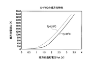
- FIG. 5 is a diagram showing forward voltage characteristics of the SiC diode.
- the junction temperature (Tj) is used as a parameter, and the change of the forward current (on current) with respect to the forward saturation voltage (on voltage) is shown.
- the temperature dependence of the forward saturation voltage in the SiC diode has a characteristic that the forward saturation voltage increases as the junction temperature increases with the same forward current value. Contrary to the characteristics of the diode.
- the SiC diode is an element having a positive temperature coefficient in voltage drop characteristics during conduction.
- the forward saturation voltage characteristics of these series-connected FWD groups are the same as the forward saturation voltage characteristics of Si diodes.
- the forward saturation voltage characteristic is added.
- the temperature characteristic of the SiC diode works so as to cancel the temperature characteristic of the Si diode
- the temperature dependence of the forward saturation voltage in the FWD group is much smaller than that of the Si-FWD alone. Therefore, thermal runaway will not occur if there is no extreme difference in the forward voltage characteristics of Si-FWDs connected in parallel due to manufacturing variations, etc., so the time and labor required for element selection can be reduced. Thus, the difficulty of element selection is eliminated.
- each FWD (Si-FWD, SiC-FWD) constituting the FWD group should have a breakdown voltage smaller than the breakdown voltage of the switching elements connected in reverse parallel (the breakdown voltage between the collector and emitter of the Si-IGBT). Therefore, it is possible to make a low-priced power module and contribute to the cost reduction of the apparatus.
- Si diodes since the manufacturing technology of Si diodes is relatively established, even if the withstand voltage is increased, it is not expensive. On the other hand, SiC diodes have a relatively short history of manufacture, and those with a high breakdown voltage are very expensive. However, if Si-FWD and SiC-FWD are connected in series, the breakdown voltage of the switching elements connected in reverse parallel can be shared (divided) between Si-FWD and SiC-FWD, so SiC-FWD Can be made smaller than that of the entire switching element.
- a withstand voltage of 3.3 kV is required as a switching element used in a power converter for a railway vehicle
- an equivalent withstand voltage is also required for the FWDs connected in series.
- the breakdown voltage of the diode element is almost determined by the magnitude of the leakage current.
- the currents flowing through these two diode elements are the same, so that the applied voltage is higher in the element having a small leak current than in the element having a large leak current. Therefore, an element with a small leakage current is required to have a higher breakdown voltage than an element with a large leakage current. Therefore, in the above example, the leakage current of SiC-FWD is larger than that of Si-FWD.
- the breakdown voltage of Si-FWD is set to 1.5 kV and the breakdown voltage of SiC-FWD is set to 1.8 kV.
- the SiC-FWD which has a smaller on-voltage than the Si-FWD, an effect of reducing the on-voltage of the entire FWD group can be obtained.
- the leakage current of the element on which the breakdown voltage is desired to be reduced that is, the Si-FWD leakage current may be made larger than the leakage current of the SiC-FWD.
- the Si-IGBT, the Si-FWD having a negative temperature coefficient when conducting voltage drop, and the positive voltage dropping characteristic when conducting voltage drop Since the FWD group in which SiC-FWD having a coefficient is connected in series with each other, two element pairs are formed in antiparallel, and these two element pairs are connected in parallel. In addition, it is possible to suppress a decrease in thermal runaway due to manufacturing variations and the like, and it is possible to reduce time and labor for element selection, and simplification of design and manufacturing.
- the allowable value of variation between the forward saturation voltage of one FWD and the forward saturation voltage of the other FWD in parallel application can be increased as compared with the conventional case.
- the yield of power semiconductor modules in parallel applications can be improved, and an increase in manufacturing cost can be suppressed.
- the breakdown voltage of the entire switching element connected in reverse parallel can be shared by Si-FWD and SiC-FWD, both Si-FWD and SiC-FWD are low.
- a pressure-resistant product can be used, and the FWD can be reduced in cost, thereby contributing to the reduction in the cost of the semiconductor power module and the cost of the power conversion device.
- an SiC-FWD1 element and an Si-FWD1 element are used as two semiconductor elements connected in series.
- each element is not necessary that each element is a single element.
- a plurality of SiC-FWD elements and a Si-FWD1 element may be connected in series, or a SiC-FWD1 element and a plurality of Si-FWD elements may be connected in series.
- SiC-FWD is used for one of the semiconductor elements constituting the FWD group in the power semiconductor module.
- the present invention is not limited to this SiC-FWD.
- SiC is an example of a semiconductor called a wide band gap semiconductor.
- a semiconductor formed using a gallium nitride-based material or diamond belongs to a wide band gap semiconductor, and its characteristics are also SiC. There are many similarities to. Therefore, a configuration using a wide band gap semiconductor other than SiC also forms the gist of the present invention.
- Si-FWD is used for the other of the semiconductor elements constituting the FWD group in the power semiconductor module, but the present invention is not limited to this Si-FWD.
- Si is an example of a semiconductor called a narrow band gap semiconductor, and other semiconductors may be used as long as the voltage drop characteristics during conduction have a negative temperature coefficient as shown in FIG. Absent.
- a configuration using both diodes having one-way conductivity is disclosed, but either one is an element having one-way conductivity. It does not matter if the other has one-way conductivity. That is, when one of the FWD groups is a unidirectional conductive element, the other may be a conductive element having no unidirectionality. However, between these unidirectional conducting elements and the conducting elements, the voltage drop characteristics during conduction need to be opposite to each other.
- Embodiment 2 FIG. In the first embodiment, an example in which SiC-FWD is used for one of the semiconductor elements constituting the FWD group in the power semiconductor module and Si-FWD is used for the other is shown in the second embodiment, but in the second embodiment, SiC-FWD is used as SiC-FWD.
- SiC-SBD Schottky barrier diode
- SiC-SBD has a characteristic that the voltage drop characteristic during current conduction always has a positive temperature coefficient due to its structural characteristics. For this reason, by connecting SiC-SBD having a positive temperature coefficient and Si-FWD having a negative temperature coefficient in series, thermal runaway caused by manufacturing variations can be suppressed, and element selection can be performed. Therefore, it is possible to reduce the time and labor required for simplification of design and manufacturing.
- the on-switching loss referred to here is a transient loss that occurs in the transistor element of the switching element UNI when the switching element UNI is turned on, for example, when the switching element UNI shifts from the off state to the on state.
- FIG. 6 is a comparative diagram showing a current simulation waveform when the IGBT is turned on in the switching element.
- FIG. 6 shows switching waveforms when one Si diode element is used as the FWD, and when one Si diode element and one SiC-SBD element are connected in series.
- the main parameters used for the calculation are as follows.
- FIG. 7 is a comparative diagram showing a simulation waveform of the FWD recovery current corresponding to FIG.
- the turn-on loss and the recovery loss increase as the peak value of the recovery current and the time width of the recovery current increase.
- the peak value of recovery current and the recovery current time are obtained by adopting a series connection configuration of one Si diode element and one SiC-SBD element. Both widths can be greatly reduced. That is, according to the configuration of the present embodiment, both the turn-on loss and the recovery loss can be made extremely small.
- the turn-on loss is reduced from 0.34 mJ / pulse to 0.11 mJ / pulse, and the recovery loss is reduced from 0.45 mJ / pulse to 1 ⁇ J / pulse. Therefore, the on-switching loss, which is the sum of the turn-on loss and the recovery loss, is 0.79 mJ to 0.111 mJ, which is a reduction rate of about 86%.
- the above example is a calculation example when an element having a rated voltage of 600 V and a rated current of about 20 A is used.
- the rated voltage and the rated current are increased, further reduction of the on-switching loss can be expected.
- the chip thickness (substrate thickness) of the Si diode inevitably increases, and the volume of the withstand voltage layer in the Si diode increases. If the volume of the breakdown voltage layer in the Si diode increases, the charge accumulated in the breakdown voltage layer increases. For this reason, the recovery current including the current when sweeping out the accumulated charge is very large in accordance with the rated voltage and the rated current only with the Si diode.
- the recovery current of SiC-SBD is almost constant regardless of the rated voltage and rated current. For this reason, if the rated voltage and the rated current are increased, the effect of reducing the on-switching loss is inevitably increased.
- SiC-SBD is used for one of the semiconductor elements constituting the FWD group in the power semiconductor module, but the present invention is not limited to this SiC-SBD.
- SiC is an example of a semiconductor called a wide band gap semiconductor.
- a semiconductor formed using a gallium nitride-based material or diamond belongs to a wide band gap semiconductor, and its characteristics are also SiC. There are many similarities to. Therefore, a configuration using a wide band gap semiconductor other than SiC also forms the gist of the present invention.
- an SiC-SBD1 element and an Si-FWD1 element are used as two semiconductor elements connected in series.
- each element is not necessary that each element is a single element.
- a plurality of SiC-SBD elements and a Si-FWD1 element may be connected in series, or a SiC-SBD1 element and a plurality of Si-FWD elements may be connected in series.
- Si-FWD is used for the other of the semiconductor elements constituting the FWD group in the power semiconductor module, but the present invention is not limited to this Si-FWD.
- Si is an example of a semiconductor called a narrow band gap semiconductor, and a configuration using a narrow band gap semiconductor having a negative temperature coefficient in the voltage drop characteristic during conduction as shown in FIG. 3 is also included in the gist of the present invention.
- SiC-SBD and Si-FWD diodes having both unidirectional conductivity are used as semiconductor elements constituting the FWD group in the power semiconductor module.
- SiC-SBD is disclosed.
- the elements connected in series to each other need not be elements having unidirectional conductivity but may be simple conduction elements.
- the voltage drop characteristic during conduction has a positive temperature coefficient
- the element is stable in operation only by the element, and does not exhibit the above-described thermal runaway state. Therefore, the voltage drop characteristic when conducting the diode element connected in series with the SiC-SBD may be either positive or negative voltage drop characteristic.
- Embodiment 3 FIG.
- the Si-IGBT is used as the transistor element in the switching element (see FIG. 2).
- each of the two Si-IGBTs in the parallel application is replaced with a SiC-MOSFET ( A configuration of a metal oxide semiconductor field effect transistor) will be described.
- the variation between the forward saturation voltage of one FWD and the forward saturation voltage of the other FWD in the parallel application is not as large as the FWD.
- the transistor element may be required.
- FIG. 8 is a diagram showing the temperature dependence of the current-voltage characteristics in the linear region of the SiC-MOSFET.
- the SiC-MOSFET has a positive temperature coefficient in the voltage drop characteristic when current conduction is appropriate, and thus operates so as to balance each other when connected in parallel.
- an SiC-MOSFET is a unipolar device in which the charge for carrying current is only electrons, and therefore has almost no residual charge inside the SiC-MOSFET at the time of turn-off when shifting from an on state to an off state.
- FIG. 9 is a schematic diagram relating to turn-off current waveforms of Si-IGBT and SiC-MOSFET. Since the Si-IGBT has a tail current as shown in the figure, there is a turn-off loss due to the tail current. On the other hand, since the SiC-MOSFET has a structure having almost no residual charge, there is almost no tail current at turn-off. Therefore, by using SiC-MOSFET instead of Si-IGBT as the transistor element in the switching element, turn-off loss can be reduced, the cooler of the power conversion device can be downsized, and the energy saving effect can be increased. become.
- the Si-IGBT can be manufactured according to design, either having a positive temperature characteristic or having a negative temperature characteristic.
- a unipolar device such as a MOSFET is not limited to SiC, and inevitably has a positive temperature coefficient, so that it is easy to design a power semiconductor module according to the present embodiment. Therefore, it is a very useful device in the power semiconductor module of the present embodiment.
- SiC is an example of a semiconductor called a wide band gap semiconductor.
- a semiconductor formed using a gallium nitride-based material or diamond belongs to a wide band gap semiconductor, and its characteristics are also SiC. There are many similarities to. Therefore, a configuration using a wide band gap semiconductor other than SiC also forms the gist of the present invention.
- the configuration examples of the power semiconductor modules according to the first to third embodiments have been described above.
- the power semiconductor modules according to the first to third embodiments are suitable for use in power conversion devices mounted on railway vehicles and automobiles. It is.
- the conduction current on the FWD side becomes very large at the time of braking or regenerative operation. Therefore, as shown in the simulation result, the effect of reducing the on-switching loss is increased, and the power conversion device It is effective for improving efficiency and reducing costs.
- the present invention is useful as a power semiconductor module that can improve the yield of power semiconductor modules in parallel applications and suppress an increase in manufacturing cost.
Landscapes
- Engineering & Computer Science (AREA)
- Power Engineering (AREA)
- Life Sciences & Earth Sciences (AREA)
- Sustainable Development (AREA)
- Sustainable Energy (AREA)
- Transportation (AREA)
- Mechanical Engineering (AREA)
- Inverter Devices (AREA)
Abstract
Description
まず、本発明の実施の形態1にかかる電力変換装置について説明する。図1は、実施の形態1にかかる電力変換装置の概略の機能構成を示す図であり、鉄道車両1に搭載される電力変換装置10の一構成例を示している。図1に示すように、電力変換装置10は、コンバータ12、コンデンサ14およびインバータ16を備えて構成される。鉄道車両1には、電力変換装置10の入力端側に配置されてコンバータ12に接続される変圧器6および、電力変換装置10の出力端側に配置されてインバータ16に接続され、電力変換装置10からの電力供給を受けて車両を駆動する電動機18が搭載されている。なお、電動機18としては、誘導電動機や同期電動機が好適である。
First, the power conversion device according to the first embodiment of the present invention will be described. FIG. 1 is a diagram illustrating a schematic functional configuration of the power conversion device according to the first embodiment, and illustrates a configuration example of the
実施の形態1では、パワー半導体モジュールにおけるFWD群を構成する半導体素子の一方にSiC-FWDを用い、他方にSi-FWDを用いる例を示したが、実施の形態2では、SiC-FWDとしてSiCショットキーバリアダイオード(SiC-SBD)を用いる例を説明する。
In the first embodiment, an example in which SiC-FWD is used for one of the semiconductor elements constituting the FWD group in the power semiconductor module and Si-FWD is used for the other is shown in the second embodiment, but in the second embodiment, SiC-FWD is used as SiC-FWD. An example using a Schottky barrier diode (SiC-SBD) will be described.
(a)定格電圧:600V程度
(b)定格電流:20A程度
(2)スイッチング波形の計算条件
(a)負荷電流:18A
(b)電圧:350V (1) Rating of each element model of Si-FWD and SiC-SBD (a) Rated voltage: about 600V (b) Rated current: about 20A (2) Calculation condition of switching waveform (a) Load current: 18A
(B) Voltage: 350V
実施の形態1,2では、スイッチング素子におけるトランジスタ素子としてSi-IGBTを使用しているが(図2参照)、この実施の形態では、並列応用における2つのSi-IGBTのそれぞれをSiC-MOSFET(Metal Oxide Semiconductor Field Effect Transistor)とする構成について説明する。実施の形態1,2では、並列応用における一方のFWDの順方向飽和電圧と他方のFWDの順方向飽和電圧とのばらつきに着目したが、このような素子間のばらつきは、FWD程ではないものの使用態様によっては、トランジスタ素子について求められる場合がある。
In the first and second embodiments, the Si-IGBT is used as the transistor element in the switching element (see FIG. 2). In this embodiment, each of the two Si-IGBTs in the parallel application is replaced with a SiC-MOSFET ( A configuration of a metal oxide semiconductor field effect transistor) will be described. In the first and second embodiments, attention is paid to the variation between the forward saturation voltage of one FWD and the forward saturation voltage of the other FWD in the parallel application. However, the variation between the elements is not as large as the FWD. Depending on the mode of use, the transistor element may be required.
2 架線
3 集電装置
4 車輪
5 レール
6 変圧器
10 電力変換装置
12 コンバータ
14 コンデンサ
16 インバータ
18 電動機
20 パワー半導体モジュール
22 第1のパワーモジュール
24,34 FWD群
24a,34a FWD(Si-FWD)
24b,34b FWD(SiC-FWD)
25,35 IGBT(Si-IGBT)
26 素子対(第1の素子対)
32 第2のパワーモジュール
36 素子対(第2の素子対)
C コレクタ電極
E エミッタ電極
UNC,VNC,UNI,VNI,WNI,UPC,VPC,UPI,VPI,WPI スイッチング素子 DESCRIPTION OF
24b, 34b FWD (SiC-FWD)
25, 35 IGBT (Si-IGBT)
26 element pair (first element pair)
32
C Collector electrode E Emitter electrode UNC, VNC, UNI, VNI, WNI, UPC, VPC, UPI, VPI, WPI Switching element
Claims (22)
- 第1のスイッチング素子と、ワイドバンドギャップ半導体にて形成されるショットキーバリア型の第1の一方向性導通素子と導通時の電圧降下特性が負の温度係数を有するナローバンドギャップ半導体にて形成される第1の導通素子とが直列接続された第1の素子群と、が逆並列に接続されてなる第1の素子対と、
第2のスイッチング素子と、ワイドバンドギャップ半導体にて形成されるショットキーバリア型の第2の一方向性導通素子と導通時の電圧降下特性が負の温度係数を有するナローバンドギャップ半導体にて形成される第2の導通素子とが直列接続された第2の素子群と、が逆並列に接続されてなる第2の素子対と、
を有し、
これら第1および第2の素子対が並列に接続されて構成されていることを特徴とするパワー半導体モジュール。 The first switching element, the first Schottky barrier type unidirectional conducting element formed of a wide band gap semiconductor, and the narrow band gap semiconductor having a negative temperature coefficient in voltage drop characteristics when conducting. A first element pair in which a first conductive element connected in series is connected in reverse parallel;
A second switching element, a Schottky barrier type second unidirectional conducting element formed of a wide band gap semiconductor, and a narrow band gap semiconductor having a negative temperature coefficient in voltage drop characteristics during conduction. A second element group in which a second conductive element is connected in series, and a second element pair connected in antiparallel,
Have
A power semiconductor module, wherein the first and second element pairs are connected in parallel. - 前記第1および第2の導通素子は、一方向性導通素子であることを特徴とする請求項1に記載のパワー半導体モジュール。 The power semiconductor module according to claim 1, wherein the first and second conductive elements are unidirectional conductive elements.
- 前記第1および第2のスイッチング素子は、ワイドバンドギャップ半導体にて形成されるユニポーラ型のスイッチング素子であることを特徴とする請求項1に記載のパワー半導体モジュール。 The power semiconductor module according to claim 1, wherein the first and second switching elements are unipolar switching elements formed of a wide band gap semiconductor.
- 前記ワイドバンドギャップ半導体は、炭化ケイ素、窒化ガリウム系材料または、ダイヤモンドを用いた半導体であることを特徴とする請求項1~3の何れか1項に記載のパワー半導体モジュール。 The power semiconductor module according to any one of claims 1 to 3, wherein the wide band gap semiconductor is a semiconductor using silicon carbide, a gallium nitride-based material, or diamond.
- 正側アームを構成するパワー半導体モジュールと、負側アームを構成するパワー半導体モジュールとが直列接続されてなるレグを複数組有し、並列接続された複数組のレグに印加される直流電圧または交流電圧を所望の交流電圧に変換して出力する電力変換装置において、
前記各パワー半導体モジュールは、
第1のスイッチング素子と、ワイドバンドギャップ半導体にて形成されるショットキーバリア型の第1の一方向性導通素子と導通時の電圧降下特性が負の温度係数を有するナローバンドギャップ半導体にて形成される第1の導通素子とが直列接続された第1の素子群と、が逆並列に接続されてなる第1の素子対と、
第2のスイッチング素子と、ワイドバンドギャップ半導体にて形成されるショットキーバリア型の第2の一方向性導通素子と導通時の電圧降下特性が負の温度係数を有するナローバンドギャップ半導体にて形成される第2の導通素子とが直列接続された第2の素子群と、が逆並列に接続されてなる第2の素子対と、
が並列に接続されて構成されていることを特徴とする電力変換装置。 Direct current voltage or alternating current applied to multiple sets of legs connected in parallel, having multiple sets of power semiconductor modules constituting the positive arm and power semiconductor modules constituting the negative arm connected in series In the power conversion device that converts the voltage into a desired AC voltage and outputs it,
Each of the power semiconductor modules is
The first switching element, the first Schottky barrier type unidirectional conducting element formed of a wide band gap semiconductor, and the narrow band gap semiconductor having a negative temperature coefficient in voltage drop characteristics when conducting. A first element pair in which a first conductive element connected in series is connected in reverse parallel;
A second switching element, a Schottky barrier type second unidirectional conducting element formed of a wide band gap semiconductor, and a narrow band gap semiconductor having a negative temperature coefficient in voltage drop characteristics during conduction. A second element group in which a second conductive element is connected in series, and a second element pair connected in antiparallel,
Are connected in parallel, and the power converter device characterized by the above-mentioned. - 前記第1および第2の導通素子は、一方向性導通素子であることを特徴とする請求項5に記載の電力変換装置。 The power conversion device according to claim 5, wherein the first and second conducting elements are unidirectional conducting elements.
- 前記第1および第2のスイッチング素子は、ワイドバンドギャップ半導体にて形成されるユニポーラ型のスイッチング素子であることを特徴とする請求項5に記載の電力変換装置。 6. The power conversion device according to claim 5, wherein the first and second switching elements are unipolar switching elements formed of a wide band gap semiconductor.
- 前記ワイドバンドギャップ半導体は、炭化ケイ素、窒化ガリウム系材料または、ダイヤモンドを用いた半導体にて形成されることを特徴とする請求項5~7の何れか1項に記載の電力変換装置。 The power converter according to any one of claims 5 to 7, wherein the wide band gap semiconductor is formed of a semiconductor using silicon carbide, a gallium nitride-based material, or diamond.
- 正側アームを構成するパワー半導体モジュールと、負側アームを構成するパワー半導体モジュールとが直列接続されてなるレグを複数組有し、並列接続された複数組のレグに印加される直流電圧または交流電圧を所望の交流電圧に変換して出力する電力変換装置と、
前記電力変換装置からの電力供給を受けて車両を駆動する電動機と、備えた鉄道車両において、
前記各パワー半導体モジュールは、
第1のスイッチング素子と、ワイドバンドギャップ半導体にて形成されるショットキーバリア型の第1の一方向性導通素子と導通時の電圧降下特性が負の温度係数を有するナローバンドギャップ半導体にて形成される第1の導通素子とが直列接続された第1の素子群と、が逆並列に接続されてなる第1の素子対と、
第2のスイッチング素子と、ワイドバンドギャップ半導体にて形成されるショットキーバリア型の第2の一方向性導通素子と導通時の電圧降下特性が負の温度係数を有するナローバンドギャップ半導体にて形成される第2の導通素子とが直列接続された第2の素子群と、が逆並列に接続されてなる第2の素子対と、
が並列に接続されて構成されていることを特徴とする鉄道車両。 Direct current voltage or alternating current applied to multiple sets of legs connected in parallel, having multiple sets of power semiconductor modules constituting the positive arm and power semiconductor modules constituting the negative arm connected in series A power conversion device that converts the voltage into a desired AC voltage and outputs it, and
In the railway vehicle equipped with the electric motor that drives the vehicle by receiving the power supply from the power converter,
Each of the power semiconductor modules is
The first switching element, the first Schottky barrier type unidirectional conducting element formed of a wide band gap semiconductor, and the narrow band gap semiconductor having a negative temperature coefficient in voltage drop characteristics when conducting. A first element pair in which a first conductive element connected in series is connected in reverse parallel;
A second switching element, a Schottky barrier type second unidirectional conducting element formed of a wide band gap semiconductor, and a narrow band gap semiconductor having a negative temperature coefficient in voltage drop characteristics during conduction. A second element group in which a second conductive element is connected in series, and a second element pair connected in antiparallel,
A railway vehicle characterized by being connected in parallel. - 第1のスイッチング素子と、導通時の電圧降下特性が負の温度係数を有するナローバンドギャップ半導体にて形成される第1の一方向性導通素子と導通時の電圧降下特性が正の温度係数を有するワイドバンドギャップ半導体にて形成される第1の導通素子とが直列接続された第1の素子群と、が逆並列に接続されてなる第1の素子対と、
第2のスイッチング素子と、導通時の電圧降下特性が負の温度係数を有するナローバンドギャップ半導体にて形成される第2の一方向性導通素子と導通時の電圧降下特性が正の温度係数を有するワイドバンドギャップ半導体にて形成される第2の導通素子とが直列接続された第2の素子群と、が逆並列に接続されてなる第2の素子対と、
を有し、
これら第1および第2の素子対は、並列に接続されて構成され、
前記第1の導通素子の耐圧は、前記第1の一方向性導通素子の耐圧よりも小さく、
前記第2の導通素子の耐圧は、前記第2の一方向性導通素子の耐圧よりも小さい
ことを特徴とするパワー半導体モジュール。 The first switching element and the first unidirectional conducting element formed of a narrow band gap semiconductor whose voltage drop characteristic when conducting has a negative temperature coefficient and the voltage drop characteristic when conducting have a positive temperature coefficient A first element pair in which a first conductive element formed of a wide band gap semiconductor and connected in series are connected in anti-parallel; and
The second switching element and the second unidirectional conducting element formed of a narrow band gap semiconductor whose voltage drop characteristic when conducting has a negative temperature coefficient and the voltage drop characteristic when conducting have a positive temperature coefficient A second element pair in which a second conductive element formed of a wide band gap semiconductor and connected in series with each other, and a second element pair connected in anti-parallel,
Have
These first and second element pairs are configured to be connected in parallel,
The withstand voltage of the first conducting element is smaller than the withstand voltage of the first unidirectional conducting element,
The power semiconductor module, wherein the second conductive element has a withstand voltage smaller than that of the second unidirectional conductive element. - 第1のスイッチング素子と、導通時の電圧降下特性が負の温度係数を有するナローバンドギャップ半導体にて形成される第1の一方向性導通素子と導通時の電圧降下特性が正の温度係数を有するワイドバンドギャップ半導体にて形成される第1の導通素子とが直列接続された第1の素子群と、が逆並列に接続されてなる第1の素子対と、
第2のスイッチング素子と、導通時の電圧降下特性が負の温度係数を有するナローバンドギャップ半導体にて形成される第2の一方向性導通素子と導通時の電圧降下特性が正の温度係数を有するワイドバンドギャップ半導体にて形成される第2の導通素子とが直列接続された第2の素子群と、が逆並列に接続されてなる第2の素子対と、
を有し、
これら第1および第2の素子対は、並列に接続されて構成され、
前記第1の導通素子の耐圧は、前記第1の一方向性導通素子の耐圧よりも大きく、
前記第2の導通素子の耐圧は、前記第2の一方向性導通素子の耐圧よりも大きい
ことを特徴とするパワー半導体モジュール。 The first switching element and the first unidirectional conducting element formed of a narrow band gap semiconductor whose voltage drop characteristic when conducting has a negative temperature coefficient and the voltage drop characteristic when conducting have a positive temperature coefficient A first element pair in which a first conductive element formed of a wide band gap semiconductor and connected in series are connected in anti-parallel; and
The second switching element and the second unidirectional conducting element formed of a narrow band gap semiconductor whose voltage drop characteristic when conducting has a negative temperature coefficient and the voltage drop characteristic when conducting have a positive temperature coefficient A second element pair in which a second conductive element formed of a wide band gap semiconductor and connected in series with each other, and a second element pair connected in anti-parallel,
Have
These first and second element pairs are configured to be connected in parallel,
The withstand voltage of the first conducting element is greater than the withstand voltage of the first unidirectional conducting element,
The power semiconductor module, wherein the second conductive element has a withstand voltage greater than that of the second unidirectional conductive element. - 第1のスイッチング素子と、導通時の電圧降下特性が負の温度係数を有するナローバンドギャップ半導体にて形成される第1の一方向性導通素子と導通時の電圧降下特性が正の温度係数を有するワイドバンドギャップ半導体にて形成される第1の導通素子とが直列接続された第1の素子群と、が逆並列に接続されてなる第1の素子対と、
第2のスイッチング素子と、導通時の電圧降下特性が負の温度係数を有するナローバンドギャップ半導体にて形成される第2の一方向性導通素子と導通時の電圧降下特性が正の温度係数を有するワイドバンドギャップ半導体にて形成される第2の導通素子とが直列接続された第2の素子群と、が逆並列に接続されてなる第2の素子対と、
を有し、
これら第1および第2の素子対は、並列に接続されて構成され、
前記第1の導通素子の耐圧は、前記第1の一方向性導通素子の耐圧と同程度であり、
前記第1の導通素子の耐圧は、前記第1の一方向性導通素子の耐圧と同程度である
ことを特徴とするパワー半導体モジュール。 The first switching element and the first unidirectional conducting element formed of a narrow band gap semiconductor whose voltage drop characteristic when conducting has a negative temperature coefficient and the voltage drop characteristic when conducting have a positive temperature coefficient A first element pair in which a first conductive element formed of a wide band gap semiconductor and connected in series are connected in anti-parallel; and
The second switching element and the second unidirectional conducting element formed of a narrow band gap semiconductor whose voltage drop characteristic when conducting has a negative temperature coefficient and the voltage drop characteristic when conducting have a positive temperature coefficient A second element pair in which a second conductive element formed of a wide band gap semiconductor and connected in series with each other, and a second element pair connected in anti-parallel,
Have
These first and second element pairs are configured to be connected in parallel,
The withstand voltage of the first conducting element is approximately the same as the withstand voltage of the first unidirectional conducting element,
The power semiconductor module according to claim 1, wherein a breakdown voltage of the first conductive element is approximately the same as a breakdown voltage of the first unidirectional conductive element. - 前記第1および第2の導通素子は、一方向性導通素子であることを特徴とする請求項10~12の何れか1項に記載のパワー半導体モジュール。 The power semiconductor module according to any one of claims 10 to 12, wherein the first and second conductive elements are unidirectional conductive elements.
- 前記ワイドバンドギャップ半導体は、炭化ケイ素、窒化ガリウム系材料または、ダイヤモンドを用いた半導体にて形成されることを特徴とする請求項10~12の何れか1項に記載のパワー半導体モジュール。 The power semiconductor module according to any one of claims 10 to 12, wherein the wide band gap semiconductor is formed of a semiconductor using silicon carbide, a gallium nitride-based material, or diamond.
- 正側アームを構成するパワー半導体モジュールと、負側アームを構成するパワー半導体モジュールとが直列接続されてなるレグを複数組有し、並列接続された複数組のレグに印加される直流電圧または交流電圧を所望の交流電圧に変換して出力する電力変換装置において、
前記各パワー半導体モジュールは、
第1のスイッチング素子と、導通時の電圧降下特性が負の温度係数を有するナローバンドギャップ半導体にて形成される第1の一方向性導通素子と導通時の電圧降下特性が正の温度係数を有するワイドバンドギャップ半導体にて形成される第1の導通素子とが直列接続された第1の素子群と、が逆並列に接続されてなる第1の素子対と、
第2のスイッチング素子と、導通時の電圧降下特性が負の温度係数を有するナローバンドギャップ半導体にて形成される第2の一方向性導通素子と導通時の電圧降下特性が正の温度係数を有するワイドバンドギャップ半導体にて形成される第2の導通素子とが直列接続された第2の素子群と、が逆並列に接続されてなる第2の素子対と、
が並列に接続されて構成され、
前記第1の導通素子の耐圧は、前記第1の一方向性導通素子の耐圧よりも小さく、
前記第2の導通素子の耐圧は、前記第2の一方向性導通素子の耐圧よりも小さい
ことを特徴とする電力変換装置。 Direct current voltage or alternating current applied to multiple sets of legs connected in parallel, having multiple sets of power semiconductor modules constituting the positive arm and power semiconductor modules constituting the negative arm connected in series In the power conversion device that converts the voltage into a desired AC voltage and outputs it,
Each of the power semiconductor modules is
The first switching element and the first unidirectional conducting element formed of a narrow band gap semiconductor whose voltage drop characteristic when conducting has a negative temperature coefficient and the voltage drop characteristic when conducting have a positive temperature coefficient A first element pair in which a first conductive element formed of a wide band gap semiconductor and connected in series are connected in anti-parallel; and
The second switching element and the second unidirectional conducting element formed of a narrow band gap semiconductor whose voltage drop characteristic when conducting has a negative temperature coefficient and the voltage drop characteristic when conducting have a positive temperature coefficient A second element pair in which a second conductive element formed of a wide band gap semiconductor and connected in series with each other, and a second element pair connected in anti-parallel,
Are connected in parallel,
The withstand voltage of the first conducting element is smaller than the withstand voltage of the first unidirectional conducting element,
The withstand voltage of the second conducting element is smaller than the withstand voltage of the second unidirectional conducting element. - 正側アームを構成するパワー半導体モジュールと、負側アームを構成するパワー半導体モジュールとが直列接続されてなるレグを複数組有し、並列接続された複数組のレグに印加される直流電圧または交流電圧を所望の交流電圧に変換して出力する電力変換装置において、
前記各パワー半導体モジュールは、
第1のスイッチング素子と、導通時の電圧降下特性が負の温度係数を有するナローバンドギャップ半導体にて形成される第1の一方向性導通素子と導通時の電圧降下特性が正の温度係数を有するワイドバンドギャップ半導体にて形成される第1の導通素子とが直列接続された第1の素子群と、が逆並列に接続されてなる第1の素子対と、
第2のスイッチング素子と、導通時の電圧降下特性が負の温度係数を有するナローバンドギャップ半導体にて形成される第2の一方向性導通素子と導通時の電圧降下特性が正の温度係数を有するワイドバンドギャップ半導体にて形成される第2の導通素子とが直列接続された第2の素子群と、が逆並列に接続されてなる第2の素子対と、
が並列に接続されて構成され、
前記第1の導通素子の耐圧は、前記第1の一方向性導通素子の耐圧よりも大きく、
前記第2の導通素子の耐圧は、前記第2の一方向性導通素子の耐圧よりも大きい
ことを特徴とする電力変換装置。 Direct current voltage or alternating current applied to multiple sets of legs connected in parallel, having multiple sets of power semiconductor modules constituting the positive arm and power semiconductor modules constituting the negative arm connected in series In the power conversion device that converts the voltage into a desired AC voltage and outputs it,
Each of the power semiconductor modules is
The first switching element and the first unidirectional conducting element formed of a narrow band gap semiconductor whose voltage drop characteristic when conducting has a negative temperature coefficient and the voltage drop characteristic when conducting have a positive temperature coefficient A first element pair in which a first conductive element formed of a wide band gap semiconductor and connected in series are connected in anti-parallel; and
The second switching element and the second unidirectional conducting element formed of a narrow band gap semiconductor whose voltage drop characteristic when conducting has a negative temperature coefficient and the voltage drop characteristic when conducting have a positive temperature coefficient A second element pair in which a second conductive element formed of a wide band gap semiconductor and connected in series with each other, and a second element pair connected in anti-parallel,
Are connected in parallel,
The withstand voltage of the first conducting element is greater than the withstand voltage of the first unidirectional conducting element,
The withstand voltage of the second conducting element is greater than the withstand voltage of the second unidirectional conducting element. - 正側アームを構成するパワー半導体モジュールと、負側アームを構成するパワー半導体モジュールとが直列接続されてなるレグを複数組有し、並列接続された複数組のレグに印加される直流電圧または交流電圧を所望の交流電圧に変換して出力する電力変換装置において、
前記各パワー半導体モジュールは、
第1のスイッチング素子と、導通時の電圧降下特性が負の温度係数を有するナローバンドギャップ半導体にて形成される第1の一方向性導通素子と導通時の電圧降下特性が正の温度係数を有するワイドバンドギャップ半導体にて形成される第1の導通素子とが直列接続された第1の素子群と、が逆並列に接続されてなる第1の素子対と、
第2のスイッチング素子と、導通時の電圧降下特性が負の温度係数を有するナローバンドギャップ半導体にて形成される第2の一方向性導通素子と導通時の電圧降下特性が正の温度係数を有するワイドバンドギャップ半導体にて形成される第2の導通素子とが直列接続された第2の素子群と、が逆並列に接続されてなる第2の素子対と、
が並列に接続されて構成され、
前記第1の導通素子の耐圧は、前記第1の一方向性導通素子の耐圧と同程度であり、
前記第1の導通素子の耐圧は、前記第1の一方向性導通素子の耐圧と同程度である
ことを特徴とする電力変換装置。 Direct current voltage or alternating current applied to multiple sets of legs connected in parallel, having multiple sets of power semiconductor modules constituting the positive arm and power semiconductor modules constituting the negative arm connected in series In the power conversion device that converts the voltage into a desired AC voltage and outputs it,
Each of the power semiconductor modules is
The first switching element and the first unidirectional conducting element formed of a narrow band gap semiconductor whose voltage drop characteristic when conducting has a negative temperature coefficient and the voltage drop characteristic when conducting have a positive temperature coefficient A first element pair in which a first conductive element formed of a wide band gap semiconductor and connected in series are connected in anti-parallel; and
The second switching element and the second unidirectional conducting element formed of a narrow band gap semiconductor whose voltage drop characteristic when conducting has a negative temperature coefficient and the voltage drop characteristic when conducting have a positive temperature coefficient A second element pair in which a second conductive element formed of a wide band gap semiconductor and connected in series with each other, and a second element pair connected in anti-parallel,
Are connected in parallel,
The withstand voltage of the first conducting element is approximately the same as the withstand voltage of the first unidirectional conducting element,
The withstand voltage of the first conducting element is approximately the same as the withstand voltage of the first unidirectional conducting element. - 前記第1および第2の導通素子は、一方向性導通素子であることを特徴とする請求項15~17の何れか1項に記載の電力変換装置。 The power converter according to any one of claims 15 to 17, wherein the first and second conducting elements are unidirectional conducting elements.
- 前記ワイドバンドギャップ半導体は、炭化ケイ素、窒化ガリウム系材料または、ダイヤモンドを用いた半導体にて形成されることを特徴とする請求項15~17の何れか1項に記載の電力変換装置。 The power converter according to any one of claims 15 to 17, wherein the wide band gap semiconductor is formed of a semiconductor using silicon carbide, a gallium nitride-based material, or diamond.
- 正側アームを構成するパワー半導体モジュールと、負側アームを構成するパワー半導体モジュールとが直列接続されてなるレグを複数組有し、並列接続された複数組のレグに印加される直流電圧または交流電圧を所望の交流電圧に変換して出力する電力変換装置と、
前記電力変換装置からの電力供給を受けて車両を駆動する電動機と、備えた鉄道車両において、
前記各パワー半導体モジュールは、
第1のスイッチング素子と、導通時の電圧降下特性が負の温度係数を有するナローバンドギャップ半導体にて形成される第1の一方向性導通素子と導通時の電圧降下特性が正の温度係数を有するワイドバンドギャップ半導体にて形成される第1の導通素子とが直列接続された第1の素子群と、が逆並列に接続されてなる第1の素子対と、
第2のスイッチング素子と、導通時の電圧降下特性が負の温度係数を有するナローバンドギャップ半導体にて形成される第2の一方向性導通素子と導通時の電圧降下特性が正の温度係数を有するワイドバンドギャップ半導体にて形成される第2の導通素子とが直列接続された第2の素子群と、が逆並列に接続されてなる第2の素子対と、
が並列に接続されて構成され、
前記第1の導通素子の耐圧は、前記第1の一方向性導通素子の耐圧よりも小さく、
前記第2の導通素子の耐圧は、前記第2の一方向性導通素子の耐圧よりも小さい
ことを特徴とする鉄道車両。 Direct current voltage or alternating current applied to multiple sets of legs connected in parallel, having multiple sets of power semiconductor modules constituting the positive arm and power semiconductor modules constituting the negative arm connected in series A power conversion device that converts the voltage into a desired AC voltage and outputs it, and
In the railway vehicle equipped with the electric motor that drives the vehicle by receiving the power supply from the power converter,
Each of the power semiconductor modules is
The first switching element and the first unidirectional conducting element formed of a narrow band gap semiconductor whose voltage drop characteristic when conducting has a negative temperature coefficient and the voltage drop characteristic when conducting have a positive temperature coefficient A first element pair in which a first conductive element formed of a wide band gap semiconductor and connected in series are connected in anti-parallel; and
The second switching element and the second unidirectional conducting element formed of a narrow band gap semiconductor whose voltage drop characteristic when conducting has a negative temperature coefficient and the voltage drop characteristic when conducting have a positive temperature coefficient A second element pair in which a second conductive element formed of a wide band gap semiconductor and connected in series with each other, and a second element pair connected in anti-parallel,
Are connected in parallel,
The withstand voltage of the first conducting element is smaller than the withstand voltage of the first unidirectional conducting element,
The railcar characterized in that a withstand voltage of the second conducting element is smaller than a withstand voltage of the second unidirectional conducting element. - 正側アームを構成するパワー半導体モジュールと、負側アームを構成するパワー半導体モジュールとが直列接続されてなるレグを複数組有し、並列接続された複数組のレグに印加される直流電圧または交流電圧を所望の交流電圧に変換して出力する電力変換装置と、
前記電力変換装置からの電力供給を受けて車両を駆動する電動機と、備えた鉄道車両において、
前記各パワー半導体モジュールは、
第1のスイッチング素子と、導通時の電圧降下特性が負の温度係数を有するナローバンドギャップ半導体にて形成される第1の一方向性導通素子と導通時の電圧降下特性が正の温度係数を有するワイドバンドギャップ半導体にて形成される第1の導通素子とが直列接続された第1の素子群と、が逆並列に接続されてなる第1の素子対と、
第2のスイッチング素子と、導通時の電圧降下特性が負の温度係数を有するナローバンドギャップ半導体にて形成される第2の一方向性導通素子と導通時の電圧降下特性が正の温度係数を有するワイドバンドギャップ半導体にて形成される第2の導通素子とが直列接続された第2の素子群と、が逆並列に接続されてなる第2の素子対と、
が並列に接続されて構成され、
前記第1の導通素子の耐圧は、前記第1の一方向性導通素子の耐圧よりも大きく、
前記第2の導通素子の耐圧は、前記第2の一方向性導通素子の耐圧よりも大きい
ことを特徴とする鉄道車両。 Direct current voltage or alternating current applied to multiple sets of legs connected in parallel, having multiple sets of power semiconductor modules constituting the positive arm and power semiconductor modules constituting the negative arm connected in series A power conversion device that converts the voltage into a desired AC voltage and outputs it, and
In the railway vehicle equipped with the electric motor that drives the vehicle by receiving the power supply from the power converter,
Each of the power semiconductor modules is
The first switching element and the first unidirectional conducting element formed of a narrow band gap semiconductor whose voltage drop characteristic when conducting has a negative temperature coefficient and the voltage drop characteristic when conducting have a positive temperature coefficient A first element pair in which a first conductive element formed of a wide band gap semiconductor and connected in series are connected in anti-parallel; and
The second switching element and the second unidirectional conducting element formed of a narrow band gap semiconductor whose voltage drop characteristic when conducting has a negative temperature coefficient and the voltage drop characteristic when conducting have a positive temperature coefficient A second element pair in which a second conductive element formed of a wide band gap semiconductor and connected in series with each other, and a second element pair connected in anti-parallel,
Are connected in parallel,
The withstand voltage of the first conducting element is greater than the withstand voltage of the first unidirectional conducting element,
The railcar characterized in that the withstand voltage of the second conducting element is greater than the withstand voltage of the second unidirectional conducting element. - 正側アームを構成するパワー半導体モジュールと、負側アームを構成するパワー半導体モジュールとが直列接続されてなるレグを複数組有し、並列接続された複数組のレグに印加される直流電圧または交流電圧を所望の交流電圧に変換して出力する電力変換装置と、
前記電力変換装置からの電力供給を受けて車両を駆動する電動機と、備えた鉄道車両において、
前記各パワー半導体モジュールは、
第1のスイッチング素子と、導通時の電圧降下特性が負の温度係数を有するナローバンドギャップ半導体にて形成される第1の一方向性導通素子と導通時の電圧降下特性が正の温度係数を有するワイドバンドギャップ半導体にて形成される第1の導通素子とが直列接続された第1の素子群と、が逆並列に接続されてなる第1の素子対と、
第2のスイッチング素子と、導通時の電圧降下特性が負の温度係数を有するナローバンドギャップ半導体にて形成される第2の一方向性導通素子と導通時の電圧降下特性が正の温度係数を有するワイドバンドギャップ半導体にて形成される第2の導通素子とが直列接続された第2の素子群と、が逆並列に接続されてなる第2の素子対と、
が並列に接続されて構成され、
前記第1の導通素子の耐圧は、前記第1の一方向性導通素子の耐圧と同程度であり、
前記第1の導通素子の耐圧は、前記第1の一方向性導通素子の耐圧と同程度である
ことを特徴とする鉄道車両。 Direct current voltage or alternating current applied to multiple sets of legs connected in parallel, having multiple sets of power semiconductor modules constituting the positive arm and power semiconductor modules constituting the negative arm connected in series A power conversion device that converts the voltage into a desired AC voltage and outputs it, and
In the railway vehicle equipped with the electric motor that drives the vehicle by receiving the power supply from the power converter,
Each of the power semiconductor modules is
The first switching element and the first unidirectional conducting element formed of a narrow band gap semiconductor whose voltage drop characteristic when conducting has a negative temperature coefficient and the voltage drop characteristic when conducting have a positive temperature coefficient A first element pair in which a first conductive element formed of a wide band gap semiconductor and connected in series are connected in anti-parallel; and
The second switching element and the second unidirectional conducting element formed of a narrow band gap semiconductor whose voltage drop characteristic when conducting has a negative temperature coefficient and the voltage drop characteristic when conducting have a positive temperature coefficient A second element pair in which a second conductive element formed of a wide band gap semiconductor and connected in series with each other, and a second element pair connected in anti-parallel,
Are connected in parallel,
The withstand voltage of the first conducting element is approximately the same as the withstand voltage of the first unidirectional conducting element,
The railcar characterized in that the withstand voltage of the first conducting element is approximately the same as the withstand voltage of the first unidirectional conducting element.
Priority Applications (4)
| Application Number | Priority Date | Filing Date | Title |
|---|---|---|---|
| JP2011520270A JP4808290B1 (en) | 2010-03-09 | 2010-10-29 | Power semiconductor module, power conversion device and railway vehicle |
| CN201080065240.XA CN102781712B (en) | 2010-03-09 | 2010-10-29 | Power semiconductor module, electric power converter, and railway vehicle |
| US13/582,834 US9270193B2 (en) | 2010-03-09 | 2010-10-29 | Power semiconductor module, power converting apparatus, and railway car |
| EP10847489.1A EP2546972A4 (en) | 2010-03-09 | 2010-10-29 | Power semiconductor module, electric power converter, and railway vehicle |
Applications Claiming Priority (2)
| Application Number | Priority Date | Filing Date | Title |
|---|---|---|---|
| PCT/JP2010/053906 WO2011111175A1 (en) | 2010-03-09 | 2010-03-09 | Power semiconductor module, power conversion device, and railway vehicles |
| JPPCT/JP2010/053906 | 2010-03-09 |
Publications (1)
| Publication Number | Publication Date |
|---|---|
| WO2011111262A1 true WO2011111262A1 (en) | 2011-09-15 |
Family
ID=44563020
Family Applications (2)
| Application Number | Title | Priority Date | Filing Date |
|---|---|---|---|
| PCT/JP2010/053906 WO2011111175A1 (en) | 2010-03-09 | 2010-03-09 | Power semiconductor module, power conversion device, and railway vehicles |
| PCT/JP2010/069383 WO2011111262A1 (en) | 2010-03-09 | 2010-10-29 | Power semiconductor module, electric power converter, and railway vehicle |
Family Applications Before (1)
| Application Number | Title | Priority Date | Filing Date |
|---|---|---|---|
| PCT/JP2010/053906 WO2011111175A1 (en) | 2010-03-09 | 2010-03-09 | Power semiconductor module, power conversion device, and railway vehicles |
Country Status (4)
| Country | Link |
|---|---|
| US (1) | US9270193B2 (en) |
| EP (1) | EP2546972A4 (en) |
| CN (1) | CN102781712B (en) |
| WO (2) | WO2011111175A1 (en) |
Cited By (10)
| Publication number | Priority date | Publication date | Assignee | Title |
|---|---|---|---|---|
| JP5084973B1 (en) * | 2011-10-17 | 2012-11-28 | 三菱電機株式会社 | Motor control device |
| WO2013046461A1 (en) * | 2011-09-30 | 2013-04-04 | 三菱電機株式会社 | Vector control device for electric motor, electric motor, vehicle drive system, and vector control method for electric motor |
| WO2013111326A1 (en) * | 2012-01-27 | 2013-08-01 | 三菱電機株式会社 | Motor drive circuit and permanent magnet synchronous motor |
| JP2013162658A (en) * | 2012-02-07 | 2013-08-19 | Mitsubishi Electric Corp | Power conversion device |
| JP2013236507A (en) * | 2012-05-10 | 2013-11-21 | Fuji Electric Co Ltd | Power semiconductor module |
| JP2015503898A (en) * | 2011-12-30 | 2015-02-02 | ゼネラル・エレクトリック・カンパニイ | Damage protection for power supply systems |
| EP2811644A4 (en) * | 2012-01-30 | 2016-01-20 | Mitsubishi Electric Corp | Motor control device |
| US9712070B2 (en) | 2013-06-04 | 2017-07-18 | Toshiba Mitsubishi-Electric Industrial Systems Corporation | Power conversion device |
| WO2022039276A1 (en) * | 2020-08-20 | 2022-02-24 | 株式会社Flosfia | Semiconductor device |
| WO2022039277A1 (en) * | 2020-08-20 | 2022-02-24 | 株式会社Flosfia | Semiconductor device |
Families Citing this family (10)
| Publication number | Priority date | Publication date | Assignee | Title |
|---|---|---|---|---|
| US9193745B2 (en) * | 2011-11-15 | 2015-11-24 | Universal Display Corporation | Heteroleptic iridium complex |
| US20150108958A1 (en) * | 2012-12-28 | 2015-04-23 | Eaton Corporation | Hybrid three-level t-type converter for power applications |
| US9680376B2 (en) * | 2014-02-28 | 2017-06-13 | Cree, Inc. | Power conversion electronics having conversion and inverter circuitry |
| US9461547B2 (en) | 2014-03-07 | 2016-10-04 | Cree, Inc. | Converter circuitry |
| CN104467448A (en) * | 2014-12-12 | 2015-03-25 | 韩亚兰 | Alternating-current chopped wave main circuit structure for diode follow current |
| US10177228B2 (en) | 2015-01-14 | 2019-01-08 | Mitsubishi Electric Corporation | Semiconductor device and method for manufacturing semiconductor device |
| EP3607648B1 (en) * | 2017-04-05 | 2021-07-07 | TVS Motor Company Limited | Control system for a vehicle |
| JP6863033B2 (en) | 2017-04-18 | 2021-04-21 | 株式会社デンソー | Parallel drive circuit for voltage-driven semiconductor elements |
| US10778114B2 (en) | 2018-01-31 | 2020-09-15 | Gan Systems Inc. | Enhanced performance hybrid three-level inverter/rectifier |
| WO2019224136A1 (en) * | 2018-05-21 | 2019-11-28 | Scandinova Systems Ab | Output rectifier and arrangement comprising an output rectifier |
Citations (6)
| Publication number | Priority date | Publication date | Assignee | Title |
|---|---|---|---|---|
| JPS62202548A (en) | 1986-02-28 | 1987-09-07 | Mitsubishi Electric Corp | Semiconductor device |
| JP2001245479A (en) * | 2000-02-29 | 2001-09-07 | Mitsubishi Electric Corp | Power semiconductor module |
| JP2002369498A (en) * | 2001-06-07 | 2002-12-20 | Fuji Electric Co Ltd | Gate drive circiuit for power semiconductor element |
| JP2003199354A (en) * | 2001-12-25 | 2003-07-11 | Toshiba Corp | Power converter |
| JP2003284318A (en) * | 2002-01-17 | 2003-10-03 | Mitsubishi Electric Corp | Drive circuit for power semiconductor element |
| JP2008072863A (en) * | 2006-09-15 | 2008-03-27 | Sanken Electric Co Ltd | Overheating detection circuit for power supply unit |
Family Cites Families (7)
| Publication number | Priority date | Publication date | Assignee | Title |
|---|---|---|---|---|
| US4398142A (en) | 1981-10-09 | 1983-08-09 | Harris Corporation | Kelvin-connected buried zener voltage reference circuit |
| JP2002199745A (en) * | 2000-12-27 | 2002-07-12 | Mitsubishi Electric Corp | Power semiconductor device, power arm and inverter circuit |
| JP3621659B2 (en) * | 2001-05-09 | 2005-02-16 | 三菱電機株式会社 | Power conversion system |
| JP5358882B2 (en) * | 2007-02-09 | 2013-12-04 | サンケン電気株式会社 | Composite semiconductor device including rectifying element |
| WO2008152686A1 (en) * | 2007-06-11 | 2008-12-18 | Mitsubishi Electric Corporation | Power conversion device |
| JP2009159184A (en) * | 2007-12-26 | 2009-07-16 | Hitachi Ltd | Circuit device having freewheel diode, circuit device using diode, and electric power converter using the circuit device |
| JP2010238835A (en) * | 2009-03-31 | 2010-10-21 | Fuji Electric Systems Co Ltd | Combined semiconductor rectifying device and electric power converter using the same |
-
2010
- 2010-03-09 WO PCT/JP2010/053906 patent/WO2011111175A1/en active Application Filing
- 2010-10-29 CN CN201080065240.XA patent/CN102781712B/en not_active Expired - Fee Related
- 2010-10-29 US US13/582,834 patent/US9270193B2/en not_active Expired - Fee Related
- 2010-10-29 WO PCT/JP2010/069383 patent/WO2011111262A1/en active Application Filing
- 2010-10-29 EP EP10847489.1A patent/EP2546972A4/en not_active Withdrawn
Patent Citations (6)
| Publication number | Priority date | Publication date | Assignee | Title |
|---|---|---|---|---|
| JPS62202548A (en) | 1986-02-28 | 1987-09-07 | Mitsubishi Electric Corp | Semiconductor device |
| JP2001245479A (en) * | 2000-02-29 | 2001-09-07 | Mitsubishi Electric Corp | Power semiconductor module |
| JP2002369498A (en) * | 2001-06-07 | 2002-12-20 | Fuji Electric Co Ltd | Gate drive circiuit for power semiconductor element |
| JP2003199354A (en) * | 2001-12-25 | 2003-07-11 | Toshiba Corp | Power converter |
| JP2003284318A (en) * | 2002-01-17 | 2003-10-03 | Mitsubishi Electric Corp | Drive circuit for power semiconductor element |
| JP2008072863A (en) * | 2006-09-15 | 2008-03-27 | Sanken Electric Co Ltd | Overheating detection circuit for power supply unit |
Non-Patent Citations (1)
| Title |
|---|
| See also references of EP2546972A4 * |
Cited By (19)
| Publication number | Priority date | Publication date | Assignee | Title |
|---|---|---|---|---|
| WO2013046461A1 (en) * | 2011-09-30 | 2013-04-04 | 三菱電機株式会社 | Vector control device for electric motor, electric motor, vehicle drive system, and vector control method for electric motor |
| US9246428B2 (en) | 2011-09-30 | 2016-01-26 | Mitsubishi Electric Corporation | Vector control device for an electric motor that controls an electric power converter that converts DC power to AC power, electric motor, vehicle drive system, and vector control method for electric motor |
| JP5503810B2 (en) * | 2011-09-30 | 2014-05-28 | 三菱電機株式会社 | Vector control device for electric motor, vehicle drive system |
| EP2763311A4 (en) * | 2011-09-30 | 2016-01-13 | Mitsubishi Electric Corp | Vector control device for electric motor, electric motor, vehicle drive system, and vector control method for electric motor |
| JP5084973B1 (en) * | 2011-10-17 | 2012-11-28 | 三菱電機株式会社 | Motor control device |
| WO2013057780A1 (en) * | 2011-10-17 | 2013-04-25 | 三菱電機株式会社 | Motor control device |
| JP2015503898A (en) * | 2011-12-30 | 2015-02-02 | ゼネラル・エレクトリック・カンパニイ | Damage protection for power supply systems |
| WO2013111326A1 (en) * | 2012-01-27 | 2013-08-01 | 三菱電機株式会社 | Motor drive circuit and permanent magnet synchronous motor |
| EP2808997A4 (en) * | 2012-01-27 | 2016-03-23 | Mitsubishi Electric Corp | Motor drive circuit and permanent magnet synchronous motor |
| CN104054258A (en) * | 2012-01-27 | 2014-09-17 | 三菱电机株式会社 | Motor Drive Circuit And Permanent Magnet Synchronous Motor |
| JPWO2013111326A1 (en) * | 2012-01-27 | 2015-05-11 | 三菱電機株式会社 | Motor drive circuit and permanent magnet synchronous motor |
| US9231507B2 (en) | 2012-01-27 | 2016-01-05 | Mitsubishi Electric Corporation | Motor driving curcuit and permanent magnet synchronous motor |
| EP2811644A4 (en) * | 2012-01-30 | 2016-01-20 | Mitsubishi Electric Corp | Motor control device |
| US9667187B2 (en) | 2012-01-30 | 2017-05-30 | Mitsubishi Electric Corporation | Motor control apparatus |
| JP2013162658A (en) * | 2012-02-07 | 2013-08-19 | Mitsubishi Electric Corp | Power conversion device |
| JP2013236507A (en) * | 2012-05-10 | 2013-11-21 | Fuji Electric Co Ltd | Power semiconductor module |
| US9712070B2 (en) | 2013-06-04 | 2017-07-18 | Toshiba Mitsubishi-Electric Industrial Systems Corporation | Power conversion device |
| WO2022039276A1 (en) * | 2020-08-20 | 2022-02-24 | 株式会社Flosfia | Semiconductor device |
| WO2022039277A1 (en) * | 2020-08-20 | 2022-02-24 | 株式会社Flosfia | Semiconductor device |
Also Published As
| Publication number | Publication date |
|---|---|
| US9270193B2 (en) | 2016-02-23 |
| US20120326646A1 (en) | 2012-12-27 |
| EP2546972A4 (en) | 2013-10-02 |
| EP2546972A1 (en) | 2013-01-16 |
| CN102781712A (en) | 2012-11-14 |
| WO2011111175A1 (en) | 2011-09-15 |
| CN102781712B (en) | 2014-12-10 |
Similar Documents
| Publication | Publication Date | Title |
|---|---|---|
| WO2011111262A1 (en) | Power semiconductor module, electric power converter, and railway vehicle | |
| Yuan et al. | Opportunities, challenges, and potential solutions in the application of fast-switching SiC power devices and converters | |
| JP4722229B1 (en) | Power semiconductor module, power conversion device and railway vehicle | |
| EP2590212B1 (en) | Power semiconductor module, electricity transformer device, and railway car | |
| JP4869454B1 (en) | Power semiconductor module, power conversion device and railway vehicle | |
| US11355477B2 (en) | Power semiconductor module and power conversion device | |
| JP5317413B2 (en) | Semiconductor switch and power converter using the semiconductor switch | |
| JP4594477B2 (en) | Power semiconductor module | |
| JP3621659B2 (en) | Power conversion system | |
| JP5289536B2 (en) | Power semiconductor module | |
| JP2012115134A (en) | Low-inductance, high-efficiency induction machine and method of manufacturing the same | |
| KR101432958B1 (en) | Inverter device | |
| JP2016103897A (en) | Power conversion device and railway vehicle having the same | |
| JP5546664B2 (en) | Power semiconductor module, power conversion device and railway vehicle | |
| JP5863442B2 (en) | Semiconductor module | |
| JP2015033217A (en) | Semiconductor device and power converter | |
| JP5264863B2 (en) | Power semiconductor module, power conversion device and railway vehicle | |
| Araújo et al. | Perspectives of high-voltage SiC-semiconductors in high power conversion systems for wind and photovoltaic sources | |
| Sanjeev et al. | Analysis of conduction and switching losses in two level inverter for low power applications | |
| Naayagi | Selection of power semiconductor devices for the DAB DC-DC converter for aerospace applications | |
| Ismail et al. | Characterization and System Benefits of Using 3.3 kV All-SiC MOSFET Modules in MV Power Converter Applications | |
| Divan et al. | Soft-switching–the key to high power WBG converters | |
| JP4808290B1 (en) | Power semiconductor module, power conversion device and railway vehicle | |
| Mookken | SiC MOSFETs enable high frequency in high power conversion systems | |
| Yasui et al. | Performance Improvement for 3.3 kV 1000 A High Power Density Full-SiC Power Modules with Sintered Copper Die Attach |
Legal Events
| Date | Code | Title | Description |
|---|---|---|---|
| WWE | Wipo information: entry into national phase |
Ref document number: 201080065240.X Country of ref document: CN |
|
| WWE | Wipo information: entry into national phase |
Ref document number: 2011520270 Country of ref document: JP |
|
| 121 | Ep: the epo has been informed by wipo that ep was designated in this application |
Ref document number: 10847489 Country of ref document: EP Kind code of ref document: A1 |
|
| WWE | Wipo information: entry into national phase |
Ref document number: 13582834 Country of ref document: US |
|
| REEP | Request for entry into the european phase |
Ref document number: 2010847489 Country of ref document: EP |
|
| WWE | Wipo information: entry into national phase |
Ref document number: 2010847489 Country of ref document: EP |
|
| NENP | Non-entry into the national phase |
Ref country code: DE |