WO2013108720A1 - Fuel supply device for internal combustion engine - Google Patents
Fuel supply device for internal combustion engine Download PDFInfo
- Publication number
- WO2013108720A1 WO2013108720A1 PCT/JP2013/050445 JP2013050445W WO2013108720A1 WO 2013108720 A1 WO2013108720 A1 WO 2013108720A1 JP 2013050445 W JP2013050445 W JP 2013050445W WO 2013108720 A1 WO2013108720 A1 WO 2013108720A1
- Authority
- WO
- WIPO (PCT)
- Prior art keywords
- plunger
- intake pipe
- pipe member
- supply device
- fuel supply
- Prior art date
Links
Images


Classifications
-
- F—MECHANICAL ENGINEERING; LIGHTING; HEATING; WEAPONS; BLASTING
- F02—COMBUSTION ENGINES; HOT-GAS OR COMBUSTION-PRODUCT ENGINE PLANTS
- F02M—SUPPLYING COMBUSTION ENGINES IN GENERAL WITH COMBUSTIBLE MIXTURES OR CONSTITUENTS THEREOF
- F02M37/00—Apparatus or systems for feeding liquid fuel from storage containers to carburettors or fuel-injection apparatus; Arrangements for purifying liquid fuel specially adapted for, or arranged on, internal-combustion engines
- F02M37/0047—Layout or arrangement of systems for feeding fuel
- F02M37/007—Layout or arrangement of systems for feeding fuel characterised by its use in vehicles, in stationary plants or in small engines, e.g. hand held tools
-
- F—MECHANICAL ENGINEERING; LIGHTING; HEATING; WEAPONS; BLASTING
- F02—COMBUSTION ENGINES; HOT-GAS OR COMBUSTION-PRODUCT ENGINE PLANTS
- F02M—SUPPLYING COMBUSTION ENGINES IN GENERAL WITH COMBUSTIBLE MIXTURES OR CONSTITUENTS THEREOF
- F02M37/00—Apparatus or systems for feeding liquid fuel from storage containers to carburettors or fuel-injection apparatus; Arrangements for purifying liquid fuel specially adapted for, or arranged on, internal-combustion engines
- F02M37/04—Feeding by means of driven pumps
- F02M37/046—Arrangements for driving diaphragm-type pumps
-
- F—MECHANICAL ENGINEERING; LIGHTING; HEATING; WEAPONS; BLASTING
- F02—COMBUSTION ENGINES; HOT-GAS OR COMBUSTION-PRODUCT ENGINE PLANTS
- F02M—SUPPLYING COMBUSTION ENGINES IN GENERAL WITH COMBUSTIBLE MIXTURES OR CONSTITUENTS THEREOF
- F02M57/00—Fuel-injectors combined or associated with other devices
- F02M57/02—Injectors structurally combined with fuel-injection pumps
- F02M57/022—Injectors structurally combined with fuel-injection pumps characterised by the pump drive
- F02M57/023—Injectors structurally combined with fuel-injection pumps characterised by the pump drive mechanical
-
- F—MECHANICAL ENGINEERING; LIGHTING; HEATING; WEAPONS; BLASTING
- F02—COMBUSTION ENGINES; HOT-GAS OR COMBUSTION-PRODUCT ENGINE PLANTS
- F02M—SUPPLYING COMBUSTION ENGINES IN GENERAL WITH COMBUSTIBLE MIXTURES OR CONSTITUENTS THEREOF
- F02M69/00—Low-pressure fuel-injection apparatus ; Apparatus with both continuous and intermittent injection; Apparatus injecting different types of fuel
- F02M69/02—Pumps peculiar thereto
-
- F—MECHANICAL ENGINEERING; LIGHTING; HEATING; WEAPONS; BLASTING
- F02—COMBUSTION ENGINES; HOT-GAS OR COMBUSTION-PRODUCT ENGINE PLANTS
- F02M—SUPPLYING COMBUSTION ENGINES IN GENERAL WITH COMBUSTIBLE MIXTURES OR CONSTITUENTS THEREOF
- F02M69/00—Low-pressure fuel-injection apparatus ; Apparatus with both continuous and intermittent injection; Apparatus injecting different types of fuel
- F02M69/04—Injectors peculiar thereto
- F02M69/042—Positioning of injectors with respect to engine, e.g. in the air intake conduit
-
- F—MECHANICAL ENGINEERING; LIGHTING; HEATING; WEAPONS; BLASTING
- F02—COMBUSTION ENGINES; HOT-GAS OR COMBUSTION-PRODUCT ENGINE PLANTS
- F02M—SUPPLYING COMBUSTION ENGINES IN GENERAL WITH COMBUSTIBLE MIXTURES OR CONSTITUENTS THEREOF
- F02M69/00—Low-pressure fuel-injection apparatus ; Apparatus with both continuous and intermittent injection; Apparatus injecting different types of fuel
- F02M69/46—Details, component parts or accessories not provided for in, or of interest apart from, the apparatus covered by groups F02M69/02 - F02M69/44
- F02M69/54—Arrangement of fuel pressure regulators
-
- F—MECHANICAL ENGINEERING; LIGHTING; HEATING; WEAPONS; BLASTING
- F04—POSITIVE - DISPLACEMENT MACHINES FOR LIQUIDS; PUMPS FOR LIQUIDS OR ELASTIC FLUIDS
- F04B—POSITIVE-DISPLACEMENT MACHINES FOR LIQUIDS; PUMPS
- F04B35/00—Piston pumps specially adapted for elastic fluids and characterised by the driving means to their working members, or by combination with, or adaptation to, specific driving engines or motors, not otherwise provided for
- F04B35/002—Piston pumps specially adapted for elastic fluids and characterised by the driving means to their working members, or by combination with, or adaptation to, specific driving engines or motors, not otherwise provided for driven by internal combustion engines
Definitions
- the present invention relates to a fuel supply device for an internal combustion engine that pressurizes fuel in a fuel tank to a pressure that can be injected into the internal combustion engine.
- This fuel injection uses a fuel supply device composed of a pump unit and a drive unit that drives the pump unit, pressurizes fuel from the fuel tank, and leads it to an engine (corresponding to an internal combustion engine). is there.
- a pump unit and a drive unit on an intake pipe member that forms a part of an intake pipe of an engine so that fuel can be supplied from the vicinity of a fuel injection position.
- a pump unit as disclosed in Patent Document 1 is attached so as to stand up along the radial direction of the intake pipe member, and a motor unit (a drive unit is attached to the end of the standing pump unit).
- a suction connection port body receiving fuel from the fuel tank
- a return fuel connection port body disharging return fuel
- the motor part (corresponding to the drive part) is attached so as to project to one side in the radial direction intersecting the intake pipe member, and the pump part is assembled to the projecting end of the motor part, and the motor part is used for suction.
- a structure in which a connection port body and a return fuel connection port body are provided is used.
- each of the fuel supply devices disclosed in Patent Document 1 and Patent Document 2 has a problem in weight balance around the intake pipe member, and has low vibration resistance against vibration and impact transmitted from the intake pipe member.
- the fuel supply device of Patent Document 1 has a layout in which a pump portion, a motor portion, a suction connection port body, and a return fuel connection port body project to one side in the radial direction of the intake pipe member.
- a heavy motor portion is disposed at a point farthest from the intake pipe member, a rotational moment centering on the intake pipe member is likely to occur in the fuel supply device due to a weight deviation.
- the suction connection port and the return fuel connection port are subjected to the weight of a hose member extending from the fuel tank and a stopper for stopping the hose member. Tends to increase, and a rotational moment tends to occur. For this reason, the fuel supply device lacks weight balance and is likely to shake with respect to vibration (engine vibration, running vibration, etc.) and impact transmitted from the intake pipe member.
- An object of the present invention is to provide a fuel supply device for an internal combustion engine that has a simple structure and can improve vibration resistance against vibration and impact transmitted from an intake pipe member.
- a fuel supply device includes a pump unit that pressurizes fuel, a drive unit that drives the pump unit, and a suction connection port body that guides sucked fuel to the pump unit. And a return connection port that discharges return fuel from the pump portion, and the pump portion is disposed on the outer peripheral portion of the intake pipe member that forms part of the intake pipe of the internal combustion engine, in the axial direction of the intake pipe member. Is provided with a drive part at one end of the pump part that intersects the intake pipe member, and a suction connection body and a return connection body at the other end of the intersecting pump part. It is characterized by that.
- a heavy drive unit is arranged at one end of the pump unit, and a suction connection port connected to a hose member extending from the fuel tank and a return connection port are arranged at the other end on the opposite side.
- the pump unit uses a configuration having a cylindrical plunger type pump unit that pressurizes fuel by reciprocating movement of the plunger, and the drive unit has a motor unit that reciprocates the plunger.
- a plunger-type pump part is supported on the outer periphery of the intake pipe member so that the axial direction of the pump part intersects with the axial direction of the intake pipe member, and the plunger-type pump part intersected with the intake pipe member
- a motor portion is provided at one end of the suction pump, and a suction connection port body and a return connection port body are provided at the other end portion of the intersecting plunger type pump portion.
- the motor part is arranged in an approximately L shape from one end of the plunger type pump part along the circumferential direction of the intake pipe member, and the center of gravity of the motor part is brought close to the intake pipe member. It is characterized by that.
- the plunger-type pump portion has a pressure regulator that maintains the discharged fuel at a predetermined pressure on the other end side where the suction connection port body and the return connection port body are disposed. .
- the invention according to claim 5 is characterized in that the motor part and the plunger type pump part are respectively arranged closest to the outer peripheral part of the intake pipe member.
- the invention according to claim 6 is characterized in that the motor part and the plunger type pump part are arranged on a circular locus centering on the axis of the intake pipe member.
- an injector for injecting fuel pressurized by the plunger type pump part into the intake pipe member, and further comprising a support part for supporting the plunger type pump part and the motor part on the intake pipe member.
- the injector is disposed at an intermediate portion of the plunger-type pump portion that intersects the intake pipe portion, and is installed so as to be able to inject into the intake pipe portion.
- the support portion includes a plunger-type pump portion and an intake pipe member opposite to the injector. It is characterized by having a stop part that connects between the parts that intersect with each other, and an anti-sway part that suppresses the shake with the plunger pump of the motor part as a fulcrum.
- the invention according to claim 8 is characterized in that the plunger type pump unit has a diaphragm type pump unit that assists the suction of the plunger type pump unit.
- the fuel supply device not only distributes the weight of the pump portion to both sides around the intake pipe member, but also when the fuel supply device is installed in a vehicle such as a motorcycle.
- the other end portion of the body is added with the weight of a hose member connected to these connection port bodies and a stopper for stopping the hose member.
- the other end side of the pump part having the mouth and the one end side of the pump part having the driving part are easily balanced in weight. Thereby, the shake of a pump part and a drive part is suppressed only by restraint with the hose member extended from a fuel tank.
- the fuel supply device has a simple structure in which the pump unit, the drive unit, the suction connection port body, and the return connection port body are arranged in a balanced manner, improving vibration resistance against vibrations and shocks transmitted from the intake pipe member, In other words, it is possible to improve vibration resistance in a state where the vehicle is installed in a vehicle such as a motorcycle.
- the vibration resistance in the fuel supply device using the plunger type pump unit which is difficult to ensure the weight balance with a simple structure, can be improved.
- the cylindrical plunger-type pump part has its center of gravity approaching the intake pipe member due to the transverse crossing arrangement, and the pump part itself is also difficult to shake, so the overall vibration resistance of the fuel supply device increases. .
- the heavy motor part since the heavy motor part is brought close to the intake pipe member, the position of the center of gravity of the motor part approaches the intake pipe member. Thereby, the rotational moment centering on the intake pipe member generated in the plunger type pump part is suppressed, and the fuel supply device is more difficult to shake.
- the heavy pressure regulator is disposed on the other end side of the plunger-type pump having the suction connection port body and the return connection port body, so that the opposite side (motor part) ) And weight. As a result, the fuel supply device becomes more difficult to shake by utilizing the pressure regulator.
- the rotational moment generated in the motor part and plunger type pump part centering on the intake pipe member is suppressed, and the fuel supply device becomes more difficult to shake.
- each part of the fuel supply device is more difficult to shake.
- the injector is installed, and the stop portion and the motor portion which connect the portion where the plunger-type pump portion intersects the intake pipe portion are shaken.
- the entire fuel supply device can be firmly fixed to the intake pipe portion with a simple structure that only uses the restraining stop portion.
- the suction function of the plunger-type pump section is enhanced, and the fuel in the fuel tank can be properly supplied to the injector from any fuel tank.
- FIG. 3 is a cross-sectional view taken along line AA in FIG. 2. Sectional drawing which shows the plunger type pump part, diaphragm type pump part, suction connection port body, return connection port body, a pressure regulator, and a motor part (part) along the BB line in FIG.
- FIG. 1 is a side view (schematic) of a vehicle, for example, a motorcycle, on which a fuel supply device to which the present invention is applied is installed.
- An arrow F in FIG. 1 indicates the front direction of the motorcycle, and an arrow R indicates the rear direction of the motorcycle.
- the motorcycle shown in FIG. 1 has a main frame member extending in the front-rear direction, for example, a main tube member 1 (only a part is shown).
- a front wheel 5 is suspended from a front end of the main tube member 1 via a front fork 3
- a rear wheel 9 is suspended from a rear end of the main tube member 1 via a swing arm member 7.
- the fuel tank 11 and the seat 12 are installed on the main tube member 1 in order from the front side.
- An acceleration / deceleration system (not shown) such as a brake pedal and a throttle grip is provided on one side (right side) sandwiching the main tube member 1, and a speed change system (not shown) such as a clutch lever and shift pedal is provided on the opposite side (left side). ) Is provided.
- an internal combustion engine for example, a single-cylinder reciprocating engine 13 (hereinafter simply referred to as the engine) in which a piston 13a is reciprocally moved. 13) is installed.
- a short pipe member 15 corresponding to an intake pipe member of the present application
- a throttle valve device 17 are sequentially connected to the side portion of the engine 13, and these include an intake port (not shown) of the engine 13 and an air cleaner (not shown).
- An intake pipe that communicates with each other is configured.
- the short pipe member 15 is provided with a fuel supply device 21 together with an electronically controlled injector 19, and these can inject fuel into the short pipe member 15.
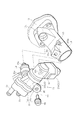
- the perspective view of FIG. 2 shows the entire fuel supply device 21 and the internal structure (dotted line portion), and the exploded perspective view of FIG. 3 shows the fuel supply device 21 removed from the short tube member 15. 4 and 5, the respective parts of the fuel supply device 21 (cross sections taken along lines AA and BB in FIG. 2) are shown.
- the fuel supply device 21 will be described with reference to FIGS. 2 to 5.
- the fuel supply device 21 includes a pump unit 25, a drive unit 27 that drives the pump unit 25, and tubular suction ports that are various connection ports.
- a connection port body 29 and a return connection port body 31 are provided.
- the pump unit 25 and the drive unit 27 are separate bodies.
- the pump unit 25, the drive unit 27, and the connection port bodies 29 and 31 are disposed on the outer peripheral portion of the short tube member 15.
- the pump unit 25 and the drive unit 27 will be described.
- the pump unit 25 has a cylindrical pump body 33 as shown in FIGS. 2 and 5.
- the pump main body 33 has a split structure divided into two in the axial direction.
- Reference numerals 33a and 33b denote divided main body portions and lid portions.
- the pump unit 25 includes a plunger-type pump unit 35 that houses various pump parts along the axial direction of the pump body 33.
- This plunger type pump part 35 has a diaphragm type pump part 49 on one end side sandwiching the pump parts of the plunger type pump part 35 and a pressure regulator 61 on the other end side, and is configured in a short cylinder shape. (Figs. 2 and 3).
- the plunger-type pump unit 35 has a cylindrical sleeve 37 incorporated along the axial direction of the pump body 33 with one end portion as a suction side and the other end portion as a discharge side.
- the sleeve 37 is configured to include a cylindrical plunger 39 that is reciprocally movable, a suction valve 41 that is assembled in the lumen of the plunger 39, and a discharge valve 43 that is assembled on the discharge side of the sleeve 37.
- the plunger pump unit 35 guides the fuel (suction fuel) in the plunger 39 to the pressurizing chamber 45 formed at the sleeve end through the suction valve 41, and adds the fuel in the heating chamber 45. It has a structure in which pressurized and pressurized fuel is discharged from the discharge valve 43.
- the injector 19 is assembled to the pump body 33 of the plunger type pump unit 35.
- the diaphragm pump 49 includes a diaphragm chamber 51 formed on the suction side of the sleeve 37, a diaphragm 53 provided so as to close the diaphragm chamber 51, and a central portion of the diaphragm 53 at the end of the plunger 39.
- a columnar fixing tool 55 to be fixed and a suction valve 57 communicating with the diaphragm chamber 51 through a passage 57a are provided.
- the diaphragm type pump unit 49 amplifies the diaphragm 51, and sucks fuel from the suction valve 57 and guides it into the plunger 39 by the pumping operation in the diaphragm chamber 51 caused by the amplitude.
- the diaphragm type pump unit 49 assists the insufficient suction function of the plunger type pump unit 35.
- the diaphragm chamber 51 also communicates with a return fuel discharge valve 59 through a passage 59a.
- the pressure regulator 61 has a structure in which a discharge chamber 63 formed on the outlet side of the discharge valve 43 is closed with a diaphragm 67 with a relief valve 65 and the diaphragm 67 is pressed by a spring member 69. It is used. That is, in the pressure regulator 61, when the discharge fuel in the discharge chamber 63 is kept at a predetermined pressure due to the displacement of the diaphragm 67 and becomes an excessive fuel pressure, the pressure is applied to the spring chamber 71 containing the spring member 69 through the relief valve 65. Of fuel is released.
- the discharge chamber 63 communicates with the inlet portion of the injector 19 through a passage 19a and a connection port portion 33c (a portion where the base portion of the injector 19 fits) formed in the pump body 33 described later. The fuel is supplied to the injector 19.
- a cylindrical motor unit 27 a in which a DC motor 75 is housed in a cylindrical motor case 73 is used.
- a cam mechanism 77 conversion mechanism that converts rotational motion into reciprocating motion is built in the end of the motor case 73 where the output shaft of the DC motor 75 is disposed.
- the cam mechanism 77 is configured, for example, by assembling an eccentric cam 79 to the output shaft of the DC motor unit 75 and fitting a frame-shaped cam receiving member 81 to the eccentric cam 79. Converts eccentric rotational motion to reciprocating motion.
- the output portion of the cam receiving member 81 is disposed on the end portion of the motor case 73, here on the side portion perpendicular to the axial direction of the motor portion 27a.
- the cylindrical pump unit 25, the cylindrical drive unit 27, and the connection ports 29 and 31 are assembled to the motorcycle so that sufficient vibration resistance is ensured in the installed state.
- the layout of each part of the fuel supply device 21 is devised.
- the pump portion 25 is arranged so as to intersect the axial direction of the short tube member 15, and one end portion of the pump portion 25 intersecting the short tube member 15. Is provided with a motor part 27a (drive part 27), and a suction connection port body 29 and a return connection port body 31 are provided at the other end of the pump part 25 on the opposite side.
- the intermediate portion (axial direction) of the pump portion 25 is disposed on the upper portion of the outer peripheral portion of the short tube member 15 so as to cross the axial direction of the short tube member 15. Is done.
- the cylindrical plunger-type pump unit 35 is arranged in a lateral direction in which the axial center direction of the plunger-type pump unit 35 and the axial center direction of the short tube member 15 intersect each other, for example, orthogonally intersect with each other. It is attached to the pipe member 15 (arrangement with a low center of gravity).
- the plunger-type pump part 35 is closest to the outer peripheral part of the short tube member 15 and is arranged at the lowest center of gravity as much as possible.
- the motor portion 27 a has a side portion of the motor case 73 having the output portion of the cam mechanism 75 so that the driving force is transmitted from the motor portion 27 a to the plunger 39. It is connected to the end of the pump body 33 having an input section.
- the entire motor unit 27 a is arranged along the downward direction, and is arranged in a different vertical direction from the plunger pump unit 35. With this layout, the entire pump part 27 a is arranged in a substantially L shape along the circumferential direction of the outer peripheral part of the intake pipe member 25, and the position of the center of gravity of the motor part 27 a is brought close to the intake pipe member 25. Note that the motor portion 27 a is closest to the outer peripheral portion of the short tube member 15.
- the suction connection port body 29 and the return connection port body 31 are end portions of the plunger type pump unit 35 (pump unit 25) opposite to the motor unit 27a. It is formed integrally with the end surface of (lid portion 33b) and protrudes forward from the end surface. Of these, the suction connection port body 29 communicates with the suction valve 57.
- a fuel supply hose member 85 (only a part of which is shown by a two-dot chain line) extending from the lower part of the fuel tank 11 is connected to the suction connection port body 29 with a stopper 86 such as a hose band (two in FIG. 4). Connected by a dotted line).
- a stopper 86 such as a hose band (two in FIG. 4).
- the return connection port body 31 communicates with the discharge valve 59.
- a return hose member 87 (only part of which is shown by a two-dot chain line) extending from the fuel tank 11 is connected to the return connection port 31 by a stopper 88 such as a hose band.
- the fuel supply device 21 When the fuel supply device 21 configured as described above is installed in a motorcycle (FIGS. 1 and 2), the fuel supply device 21 exhibits considerable vibration resistance by itself only with the layout of each part. That is, as shown in FIGS. 1 and 2, the weight of the plunger-type pump unit 35 (pump unit 25) is distributed to the left and right sides around the short pipe member 15 that intersects with the pump unit 35. In a state where the fuel supply device 21 is installed in the motorcycle, the motor portion 27a is disposed on one end side of the plunger-type pump portion 35 (pump portion 25), so that the weight balance seems to deteriorate.
- the weight of the suction connection port body 29 and the return connection port body 31 is added to the other end portion of the plunger-type pump unit 35 (pump unit 25), and the plunger connection unit 29 is connected to the connection port bodies 29 and 31.
- the weights of the hose members 85 and 87 (down from the fuel tank 11) and stoppers 86 and 88 for stopping the hose members 85 and 87 are added. Therefore, it becomes easy to balance in weight with the opposite one end side where the heavy motor part 27a is arranged. This is because the position of the plunger type pump part 35 (pump part 25) intersecting with the short pipe member 15 is determined at a point where a weight balance is easily obtained. Due to this weight balance, the swing of the plunger type pump part 35 and the motor part 27 a can be suppressed only by restraint by the hose members 85 and 87 extending from the fuel tank 11.
- the fuel supply device 21 has a simple structure in which the plunger pump 35 (pump unit 25), the motor unit 27a (drive unit 27), the suction connection port body 29, and the return connection port body 31 are arranged in a balanced manner.
- the vibration resistance against vibrations and impacts transmitted from the short tube member 15 can be improved under the condition of being mounted on a motorcycle.
- Securing the vibration resistance is effective for the fuel supply device 21 configured using the cylindrical plunger pump unit 35 and the heavy motor unit 27a, which makes it difficult to ensure the weight balance.
- the cylindrical plunger type pump unit 35 is disposed sideways, so that the position of the center of gravity is lowered, and the plunger type pump unit 35 as a whole is difficult to shake (relative to the vertical direction).
- the vibration resistance of the entire 21 can be further increased.
- the motor portion 27a is arranged in an approximately L shape along the circumferential direction of the short tube member 15, so that the position of the center of gravity of the motor portion 27a also approaches the short tube member 15 and the rotational moment about the short tube member 15 is obtained. Therefore, it is difficult for the fuel supply device 21 to shake, and the vibration resistance can be further improved.
- the fuel supply device 21 has the weight of the pressure regulator 61 as well as the plunger. Since it is added to the other end of the pump section 35 (pump section 25), it becomes easier to balance the weight with the opposite side (motor section 27a). That is, the fuel supply device 21 as a whole becomes more difficult to shake by using the pressure regulator 61, and the vibration resistance is improved.
- the fuel supply device 21 has a plunger type centered on the short pipe member 15 when the plunger type pump part 35 and the motor part 27a are arranged at points closest to the outer peripheral part of the short pipe member 15, respectively. Since the rotational moment generated in the pump part 35 and the motor part 27a is suppressed, the fuel supply device 21 becomes more difficult to shake and the vibration resistance is improved.
- the plunger-type pump unit 35 and the motor unit 27 a are arranged on a circular locus closest to the outer peripheral portion of the short tube member 15 centering on the axis of the short tube member 15.
- the vibration of each part of the fuel supply device 21 around the short tube member 15 is effectively suppressed, and the vibration resistance is effectively enhanced.
- the fuel supply device 21 when the diaphragm pump unit 37 is provided in the fuel supply device 21, the insufficient suction function of the plunger pump unit 35 is enhanced, so that the fuel supply device 21 is located at a position considerably higher than the fuel supply device 21.
- the fuel supply device 21 as shown in FIG. 1 can reliably supply fuel even in a vehicle that is substantially at the same height as the lower portion of the fuel tank 11. Regardless of the mounting position, the fuel in the fuel tank 11 can be properly supplied to the injector 19. That is, the fuel supply device 21 having high vibration resistance and high wearability can be provided.
- the fuel supply device 21 is fixed by using the injector 19 assembled to the plunger type pump unit 35 and simply using the support unit 91 as a plunger type pump.
- a simple structure is sufficient in which the portion 35 and the motor portion 27a are stopped by the short pipe member 15.
- the injector 19 has an intermediate portion (intersection portion) of the plunger-type pump portion 35 that intersects the intake pipe portion 15, that is, one end side and the other end portion of the plunger-type pump portion 35. It is disposed at an intermediate portion where the side is substantially balanced in weight, and is attached in an oblique direction by connecting the tip injection portion 19a to the intake pipe portion 15 in communication.
- a connecting port 33c (only a part of which is shown in FIGS. 2 and 3) is provided in the middle part (axial direction) of the pump body 33 so that the base of the injector 19 can be inserted and removed.
- the wall portion of the short tube member 15 is provided with a tip support portion 15a (only part of which is shown in FIGS. 2 and 3) into which the injection portion 19a of the injector 19 is removably fitted.
- the support portion 91 includes a stop portion 93 that connects portions where the plunger-type pump portion 35 and the short tube member 15 on the opposite side of the injector 19 intersect, and a plunger-type pump portion.
- the anti-sway part 97 is configured to suppress the shake of the motor part 27a with the shaft center of 35 as a fulcrum.
- the stop portion 93 is provided with, for example, a plate-like bracket portion 95 protruding from the outer peripheral portion of the intermediate portion of the pump main body 33, a base-like mounting seat 98 provided on the outer peripheral portion of the short tube member 15, and a bolt The bracket portion 95 is fastened to the mounting seat 98 by screwing the member 99.
- the steadying portion 97 is provided with, for example, a pin portion 101 in parallel with the side portion of the motor portion 27 a adjacent to the short tube member 15, and the pin portion 101 is provided on the outer peripheral portion of the short tube member 15.
- a structure is used in which a pin receiving seat 103 is provided, and the pin portion 101 is inserted into a pin hole 103 a formed in the pin receiving seat 103 when the plunger pump portion 35 is attached.
- the directions of the bracket portion 95, the screw hole 98a of the mounting seat 98, the pin portion 101, and the pin hole 103a are all set to the same oblique direction as the assembly direction (oblique direction) of the injector 19.
- the entire fuel supply device 21 is restrained by “installation of the injector 19 in the horizontal movement of the plunger-type pump part 35” and “fixed in the vertical movement of the plunger-type pump part 35 by bolting (retaining prevention). )
- the pin portion 101 can be firmly fixed with a simple structure in which the number of fixing points,“ suppression of vibration (front-rear direction) of the motor portion 27a with the plunger pump portion 27a as a fulcrum ”, is suppressed to a minimum number.
- the present invention is not limited to one embodiment, and various modifications may be made without departing from the spirit of the present invention.
- the example in which the fuel supply device is provided in the short pipe member (the intake pipe member that constitutes a part of the intake pipe) separate from the throttle valve device has been described.
- a fuel supply device may be provided in the valve body (intake pipe member constituting a part of the intake pipe) of the valve device, and even in this case, the same effect as in the embodiment can be obtained.
Landscapes
- Engineering & Computer Science (AREA)
- Chemical & Material Sciences (AREA)
- Combustion & Propulsion (AREA)
- Mechanical Engineering (AREA)
- General Engineering & Computer Science (AREA)
- Fuel-Injection Apparatus (AREA)
- Jet Pumps And Other Pumps (AREA)
- Control Of Throttle Valves Provided In The Intake System Or In The Exhaust System (AREA)
- Details Of Reciprocating Pumps (AREA)
Abstract
Description
ところが、特許文献1及び特許文献2に開示された燃料供給装置は、いずれも吸気管部材を中心とした重量バランスに問題があり、吸気管部材から伝わる振動や衝撃に対する耐振性が低い。 Since such a fuel supply device has a heavy drive unit such as a motor unit and a solenoid unit, the fuel supply device is easily subjected to engine vibration, running vibration, and impact transmitted from the intake pipe member.
However, each of the fuel supply devices disclosed in Patent Document 1 and Patent Document 2 has a problem in weight balance around the intake pipe member, and has low vibration resistance against vibration and impact transmitted from the intake pipe member.
そこで、本発明の目的は、簡単な構造で、吸気管部材から伝わる振動や衝撃に対する耐振性の向上を図ることができる内燃機関の燃料供給装置を提供することにある。 Since the fuel supply device of Patent Document 2 is also laid out with a heavy motor portion, pump portion, suction connection port body, and return fuel connection port body from one side in the radial direction of the intake pipe member, Similarly, the fuel supply device tends to generate a rotational moment centered on the intake pipe member due to weight imbalance (such as poor weight balance), and is likely to shake due to vibration and impact transmitted from the intake pipe member.
SUMMARY OF THE INVENTION An object of the present invention is to provide a fuel supply device for an internal combustion engine that has a simple structure and can improve vibration resistance against vibration and impact transmitted from an intake pipe member.
請求項4の発明では、プランジャ式ポンプ部は、吸込用接続口体およびリターン用接続口体の配置される他方の端側に、吐出燃料を所定圧に保つプレッシャレギュレータを有することを特徴とする。 In the invention of
According to a fourth aspect of the present invention, the plunger-type pump portion has a pressure regulator that maintains the discharged fuel at a predetermined pressure on the other end side where the suction connection port body and the return connection port body are disposed. .
請求項6の発明では、モータ部とプランジャ式ポンプ部は、吸気管部材の軸心を中心とした円の軌跡上に配置されることを特徴とする。 The invention according to
The invention according to claim 6 is characterized in that the motor part and the plunger type pump part are arranged on a circular locus centering on the axis of the intake pipe member.
したがって、燃料供給装置は、ポンプ部、駆動部、吸込用接続口体およびリターン用接続口体をバランスよく配置するという簡単な構造で、吸気管部材から伝わる振動や衝撃に対する耐振性の向上、さらに述べれば自動二輪車など車両に設置した状態における耐振性の向上を図ることができる。 According to the first aspect of the present invention, the fuel supply device not only distributes the weight of the pump portion to both sides around the intake pipe member, but also when the fuel supply device is installed in a vehicle such as a motorcycle. In addition to the weight of the suction connection port body and the return connection port body, the other end portion of the body is added with the weight of a hose member connected to these connection port bodies and a stopper for stopping the hose member. The other end side of the pump part having the mouth and the one end side of the pump part having the driving part are easily balanced in weight. Thereby, the shake of a pump part and a drive part is suppressed only by restraint with the hose member extended from a fuel tank. That is, when the pump unit and the drive unit are installed in a vehicle such as a motorcycle, the pump unit and the drive unit are less likely to shake due to vibration and impact from the intake pipe member.
Therefore, the fuel supply device has a simple structure in which the pump unit, the drive unit, the suction connection port body, and the return connection port body are arranged in a balanced manner, improving vibration resistance against vibrations and shocks transmitted from the intake pipe member, In other words, it is possible to improve vibration resistance in a state where the vehicle is installed in a vehicle such as a motorcycle.
請求項4の発明によれば、重量の有るプレッシャレギュレータが、吸込用接続口体およびリターン用接続口体の有るプランジャ式ポンプの他端側に配置されることで、一層、反対側(モータ部)と重量的にバランスしやすくなる。これにより、燃料供給装置は、プレッシャレギュレータを活用することで、一層、振れ難くなる。 According to the invention of
According to the fourth aspect of the present invention, the heavy pressure regulator is disposed on the other end side of the plunger-type pump having the suction connection port body and the return connection port body, so that the opposite side (motor part) ) And weight. As a result, the fuel supply device becomes more difficult to shake by utilizing the pressure regulator.
請求項6の発明によれば、さらに効果的に燃料供給装置の各部が振れ難くなる。 According to the invention of
According to the sixth aspect of the present invention, each part of the fuel supply device is more difficult to shake.
請求項8の発明によれば、プランジャ式ポンプ部の吸い込み機能が高められ、どのような地点に有る燃料タンクからでも、同燃料タンク内の燃料を適正にインジェクタへ供給することができる。 According to the seventh aspect of the present invention, by utilizing the fuel supply device which is difficult to shake, the injector is installed, and the stop portion and the motor portion which connect the portion where the plunger-type pump portion intersects the intake pipe portion are shaken. The entire fuel supply device can be firmly fixed to the intake pipe portion with a simple structure that only uses the restraining stop portion.
According to the invention of claim 8, the suction function of the plunger-type pump section is enhanced, and the fuel in the fuel tank can be properly supplied to the injector from any fuel tank.
図1は、本発明を適用した燃料供給装置を据え付けた車両、例えば自動二輪車の側面図(概略的)を示している。図1中の矢印Fは自動二輪車のフロント方向を示し、矢印Rは自動二輪車のリア方向を示している。 Hereinafter, the present invention will be described based on an embodiment shown in FIGS.
FIG. 1 is a side view (schematic) of a vehicle, for example, a motorcycle, on which a fuel supply device to which the present invention is applied is installed. An arrow F in FIG. 1 indicates the front direction of the motorcycle, and an arrow R indicates the rear direction of the motorcycle.
図2の斜視図には、この燃料供給装置21の全体および内部の構造(点線部分)が示され、図3の分解斜視図には、同燃料供給装置21を短管部材15から外した状態が示され、図4,5の断面図には、同燃料供給装置21の各部(図2中のA-A線、B-B線に沿う断面)が示されている。 The
The perspective view of FIG. 2 shows the entire
ポンプ部25は、このポンプ本体33の軸心方向に沿って各種ポンプ部品を収めたプランジャ式ポンプ部35で構成される。このプランジャ式ポンプ部35は、同プランジャ式ポンプ部35のポンプ部品を挟んだ一端側にダイヤフラム式ポンプ部49を有し、他端側にプレッシャレギュレータ61を有して、短筒形に構成されている(図2,3)。 The
The
この耐振性の確保のため、燃料供給装置21の各部のレイアウトには工夫が施されている。 The
In order to ensure this vibration resistance, the layout of each part of the
すなわち、図1および図2に示されるようにプランジャ式ポンプ部35(ポンプ部25)の重量は、同ポンプ部35と交差する短管部材15を中心に左右両側に振り分けられる。自動二輪車に燃料供給装置21が設置された状態では、プランジャ式ポンプ部35(ポンプ部25)の一端側にモータ部27aが配置されるために、重量バランスが悪くなるように見える。しかしながら、このプランジャ式ポンプ部35(ポンプ部25)の他端部には、吸込用接続口体29およびリターン用接続口体31の重量が加わるとともに、これら接続口体29、31に接続されるホース部材85,87(燃料タンク11から下がる)や同ホース部材85,87を止める止め具86,88の重量が加わる。そのため、反対側の、重量の有るモータ部27aが配置された一端側とは、重量的にバランスされやすくなる。これは、短管部材15と交差するプランジャ式ポンプ部35(ポンプ部25)の位置が、重量的なバランスの得やすい地点に定められることにもよる。この重量的なバランスにより、プランジャ式ポンプ部35やモータ部27aの振れは、燃料タンク11から延びるホース部材85,87による拘束だけで抑えられる。 When the
That is, as shown in FIGS. 1 and 2, the weight of the plunger-type pump unit 35 (pump unit 25) is distributed to the left and right sides around the
したがって、燃料供給装置21は、プランジャ式ポンプ35(ポンプ部25)、モータ部27a(駆動部27)、吸込用接続口体29およびリターン用接続口体31をバランスよく配置させるという簡単な構造で、自動二輪車に搭載した状態下において、短管部材15から伝わる振動や衝撃に対する耐振性を向上させることができる。 That is, when the plunger-
Therefore, the
このインジェクタ19の取り付けのために、ポンプ本体33の中間部分(軸心方向)には、インジェクタ19の基部が挿脱可能に嵌る接続口体33c(図2,3に一部だけ図示)が設けられ、短管部材15の壁部には、インジェクタ19の噴射部19aが挿脱可能に嵌る先端支え部15a(図2,3に一部だけ図示)が設けられている。 That is, as shown in FIGS. 2 to 4, the
For the attachment of the
これにより、燃料供給装置21の全体を、インジェクタ19の設置による「プランジャ式ポンプ部35の水平方向の動きの拘束」、ボルト止めよる「プランジャ式ポンプ部35の上下方向の動きの拘束(抜け止め)」、ピン部101による「プランジャ式ポンプ部27aを支点としたモータ部27aの振れ(前後方向)の抑え」という固定個所を最小数量に抑えた簡単な構造で強固に固定できる。 The directions of the
As a result, the entire
19 インジェクタ
21 燃料供給装置
27a モータ部(駆動部)
29 吸込用接続口体
31 リターン用接続口体
35 プランジャ式ポンプ部(ポンプ部)
37 ダイヤフラム式ポンプ部
61 プレッシャレギュレータ
93 止め部
97 振れ止め部 15 Short pipe member (intake pipe member)
19
29 Connection Port for
37 Diaphragm
Claims (8)
- 内燃機関の燃料供給装置であって、
燃料の加圧を行うポンプ部と、前記ポンプ部を駆動する駆動部と、前記ポンプ部へ吸込燃料を導く吸込用接続口体と、前記ポンプ部からのリターン燃料を吐出するリターン用接続口体とを備え、
前記ポンプ部を、内燃機関の吸気管の一部を構成する吸気管部材の外周部に、当該吸気管部材の軸心方向と交差するように支持させ、
前記吸気管部材と交差した前記ポンプ部の一方の端部に、前記駆動部を設け、
前記交差した前記ポンプ部の他方の端部に、前記吸込用接続口体およびリターン用接続口体を設けたことを特徴とする。 A fuel supply device for an internal combustion engine,
A pump unit that pressurizes fuel; a drive unit that drives the pump unit; a suction connection port that guides suction fuel to the pump unit; and a return connection port that discharges return fuel from the pump unit And
The pump part is supported on the outer peripheral part of the intake pipe member constituting a part of the intake pipe of the internal combustion engine so as to intersect the axial center direction of the intake pipe member,
The drive unit is provided at one end of the pump unit intersecting the intake pipe member,
The suction connection port body and the return connection port body are provided at the other end of the intersecting pump section. - 請求項1に記載の内燃機関の燃料供給装置であって、
前記ポンプ部は、プランジャの往復動により燃料を加圧する筒形状のプランジャ式ポンプ部を有して構成され、
前記駆動部は、前記プランジャを往復駆動するモータ部を有して構成され、
前記吸気管部材の外周部に前記プランジャ式ポンプ部が、同ポンプ部の軸心方向と前記吸気管部材の軸心方向とが交差するように支持され、
前記吸気管部材と交差した前記プランジャ式ポンプ部の一方の端部に前記モータ部が設けられ、
前記交差した前記プランジャ式ポンプ部の他方の端部に、前記吸込用接続口体およびリターン用接続口体が設けられることを特徴とする。 A fuel supply device for an internal combustion engine according to claim 1,
The pump unit is configured to have a cylindrical plunger type pump unit that pressurizes fuel by reciprocating movement of the plunger,
The drive unit includes a motor unit that reciprocates the plunger.
The plunger-type pump part is supported on the outer periphery of the intake pipe member so that the axial center direction of the pump part and the axial center direction of the intake pipe member intersect.
The motor unit is provided at one end of the plunger pump unit that intersects the intake pipe member,
The suction connection port body and the return connection port body are provided at the other end portion of the intersecting plunger-type pump section. - 請求項2に記載の内燃機関の燃料供給装置であって、
前記モータ部は、前記プランジャ式ポンプ部の一方の端部から前記吸気管部材の周方向に沿って略L形に配置され、前記モータ部の重心位置を前記吸気管部材に寄せてあることを特徴とする。 A fuel supply device for an internal combustion engine according to claim 2,
The motor unit is arranged in an approximately L shape along the circumferential direction of the intake pipe member from one end of the plunger pump unit, and the center of gravity of the motor unit is brought close to the intake pipe member. Features. - 請求項2ないし請求項3のいずれか一つに記載の内燃機関の燃料供給装置であって、
前記プランジャ式ポンプ部は、前記吸込用接続口体およびリターン用接続口体の配置される他方の端側に、吐出燃料を所定圧に保つプレッシャレギュレータを有することを特徴とする。 A fuel supply device for an internal combustion engine according to any one of claims 2 to 3,
The plunger-type pump unit has a pressure regulator that maintains the discharged fuel at a predetermined pressure on the other end side where the suction connection port body and the return connection port body are disposed. - 請求項3に記載の内燃機関の燃料供給装置であって、
前記モータ部と前記プランジャ式ポンプ部は、それぞれ前記吸気管部材の外周部に最も接近させて配置してあることを特徴とする。 A fuel supply device for an internal combustion engine according to claim 3,
The motor unit and the plunger-type pump unit are respectively arranged so as to be closest to the outer periphery of the intake pipe member. - 請求項5に記載の内燃機関の燃料供給装置であって、
前記モータ部と前記プランジャ式ポンプ部は、前記吸気管部材の軸心を中心とした円の軌跡上に配置されることを特徴とする。 A fuel supply device for an internal combustion engine according to claim 5,
The motor unit and the plunger pump unit are arranged on a circular locus centering on an axis of the intake pipe member. - 請求項3ないし請求項6のいずれか一つに記載の内燃機関の燃料供給装置であって、
前記プランジャ式ポンプ部で加圧された燃料を前記吸気管部材内へ噴射するインジェクタを有し、さらに前記プランジャ式ポンプ部および前記モータ部を前記吸気管部材に支持する支持部を有し、
前記インジェクタは、前記吸気管部分と交差する前記プランジャ式ポンプ部の中間部分に配置されて、前記吸気管部分に噴射可能に設置され、
前記支持部は、前記インジェクタとは反対側のプランジャ式ポンプ部と吸気管部材とが交差する部分間を連結する止め部と、前記モータ部の前記プランジャ式ポンプ部を支点とした振れを抑える振れ止め部とを有して構成されることを特徴とする。 A fuel supply device for an internal combustion engine according to any one of claims 3 to 6,
Having an injector for injecting fuel pressurized by the plunger type pump part into the intake pipe member, and further having a support part for supporting the plunger type pump part and the motor part on the intake pipe member,
The injector is disposed in an intermediate portion of the plunger-type pump section that intersects the intake pipe portion, and is installed so as to be able to inject into the intake pipe portion.
The support portion includes a stop portion that connects portions where the plunger-type pump portion on the opposite side of the injector and the intake pipe member intersect each other, and a swing that suppresses vibration about the plunger-type pump portion of the motor portion as a fulcrum. And a stop portion. - 請求項1ないし請求項7のいずれか一つに記載の内燃機関の燃料供給装置であって、
前記プランジャ式ポンプ部は、当該プランジャ式ポンプ部の吸い込みを助けるダイヤフラム式ポンプ部を有することを特徴とする。 A fuel supply device for an internal combustion engine according to any one of claims 1 to 7,
The plunger-type pump unit includes a diaphragm-type pump unit that assists the suction of the plunger-type pump unit.
Priority Applications (4)
| Application Number | Priority Date | Filing Date | Title |
|---|---|---|---|
| CN201380006062.7A CN104066970B (en) | 2012-01-19 | 2013-01-11 | The fuel supply system of internal combustion engine |
| BR112014017402A BR112014017402A8 (en) | 2012-01-19 | 2013-01-11 | internal combustion engine fuel supply device |
| IN5757DEN2014 IN2014DN05757A (en) | 2012-01-19 | 2013-01-11 | |
| PH12014501644A PH12014501644B1 (en) | 2012-01-19 | 2014-07-17 | Fuel supply device for internal combustion engine |
Applications Claiming Priority (2)
| Application Number | Priority Date | Filing Date | Title |
|---|---|---|---|
| JP2012008888A JP5968628B2 (en) | 2012-01-19 | 2012-01-19 | Fuel supply device for internal combustion engine |
| JP2012-008888 | 2012-01-19 |
Publications (1)
| Publication Number | Publication Date |
|---|---|
| WO2013108720A1 true WO2013108720A1 (en) | 2013-07-25 |
Family
ID=48799146
Family Applications (1)
| Application Number | Title | Priority Date | Filing Date |
|---|---|---|---|
| PCT/JP2013/050445 WO2013108720A1 (en) | 2012-01-19 | 2013-01-11 | Fuel supply device for internal combustion engine |
Country Status (7)
| Country | Link |
|---|---|
| JP (1) | JP5968628B2 (en) |
| CN (1) | CN104066970B (en) |
| BR (1) | BR112014017402A8 (en) |
| IN (1) | IN2014DN05757A (en) |
| MY (1) | MY168062A (en) |
| PH (1) | PH12014501644B1 (en) |
| WO (1) | WO2013108720A1 (en) |
Citations (6)
| Publication number | Priority date | Publication date | Assignee | Title |
|---|---|---|---|---|
| JPH03117680A (en) * | 1989-09-30 | 1991-05-20 | Yamaha Motor Co Ltd | Fuel feed device for two cycle engine |
| JPH0454974U (en) * | 1990-09-20 | 1992-05-12 | ||
| JP2003254187A (en) * | 2002-02-28 | 2003-09-10 | Honda Motor Co Ltd | Fuel pump module of vehicle |
| JP2005105987A (en) * | 2003-09-30 | 2005-04-21 | Honda Motor Co Ltd | Fuel injection device of internal combustion engine |
| JP2005133672A (en) * | 2003-10-31 | 2005-05-26 | Keihin Corp | Fuel feeding device of vehicle |
| JP2011012649A (en) * | 2009-07-06 | 2011-01-20 | Aisan Industry Co Ltd | Fuel injection device |
Family Cites Families (1)
| Publication number | Priority date | Publication date | Assignee | Title |
|---|---|---|---|---|
| US6971371B2 (en) * | 2003-09-30 | 2005-12-06 | Honda Motor Co., Ltd. | Air-fuel mixing and delivery apparatus for an internal combustion engine |
-
2012
- 2012-01-19 JP JP2012008888A patent/JP5968628B2/en not_active Expired - Fee Related
-
2013
- 2013-01-11 BR BR112014017402A patent/BR112014017402A8/en not_active IP Right Cessation
- 2013-01-11 WO PCT/JP2013/050445 patent/WO2013108720A1/en active Application Filing
- 2013-01-11 MY MYPI2014701903A patent/MY168062A/en unknown
- 2013-01-11 CN CN201380006062.7A patent/CN104066970B/en not_active Expired - Fee Related
- 2013-01-11 IN IN5757DEN2014 patent/IN2014DN05757A/en unknown
-
2014
- 2014-07-17 PH PH12014501644A patent/PH12014501644B1/en unknown
Patent Citations (6)
| Publication number | Priority date | Publication date | Assignee | Title |
|---|---|---|---|---|
| JPH03117680A (en) * | 1989-09-30 | 1991-05-20 | Yamaha Motor Co Ltd | Fuel feed device for two cycle engine |
| JPH0454974U (en) * | 1990-09-20 | 1992-05-12 | ||
| JP2003254187A (en) * | 2002-02-28 | 2003-09-10 | Honda Motor Co Ltd | Fuel pump module of vehicle |
| JP2005105987A (en) * | 2003-09-30 | 2005-04-21 | Honda Motor Co Ltd | Fuel injection device of internal combustion engine |
| JP2005133672A (en) * | 2003-10-31 | 2005-05-26 | Keihin Corp | Fuel feeding device of vehicle |
| JP2011012649A (en) * | 2009-07-06 | 2011-01-20 | Aisan Industry Co Ltd | Fuel injection device |
Also Published As
| Publication number | Publication date |
|---|---|
| BR112014017402A2 (en) | 2017-06-13 |
| PH12014501644A1 (en) | 2014-10-13 |
| IN2014DN05757A (en) | 2015-04-10 |
| CN104066970B (en) | 2016-08-24 |
| BR112014017402A8 (en) | 2017-07-04 |
| CN104066970A (en) | 2014-09-24 |
| MY168062A (en) | 2018-10-11 |
| JP5968628B2 (en) | 2016-08-10 |
| PH12014501644B1 (en) | 2014-10-13 |
| JP2013148002A (en) | 2013-08-01 |
Similar Documents
| Publication | Publication Date | Title |
|---|---|---|
| US8439146B2 (en) | Canister device for motorcycle | |
| WO2012157564A1 (en) | High-pressure fuel pump device | |
| CA2553565C (en) | Inclination angle sensor layout structure for vehicle | |
| JP5901255B2 (en) | Multiple throttle device | |
| JP2004284473A (en) | Fuel pump arrangement structure of motorcycle | |
| EP2543834A1 (en) | Breather structure of motorcycle engine | |
| JP2015074353A (en) | Saddle-riding type vehicle | |
| CN100402832C (en) | Fuel device and pump, injector | |
| JP5985190B2 (en) | Fuel injection device for internal combustion engine | |
| WO2013108720A1 (en) | Fuel supply device for internal combustion engine | |
| US20070200333A1 (en) | Arrangement structure of vehicle-use fuel pump | |
| JP2014046849A (en) | Saddle-riding type vehicle | |
| JP5957332B2 (en) | Saddle riding vehicle | |
| JP5946357B2 (en) | Saddle riding vehicle | |
| EP1939423A2 (en) | Straddle-type vehicle | |
| JP5762088B2 (en) | Motorcycle fuel supply system | |
| JP5946355B2 (en) | Saddle riding vehicle | |
| JP6308968B2 (en) | Fuel supply pump arrangement structure for small vehicles | |
| JP6072411B2 (en) | Fuel pressure control device and fuel supply device using the same | |
| CN1521038A (en) | Fuel supply unit support structure for vehicles | |
| JP5643031B2 (en) | Vehicle fuel supply device | |
| JP2018105488A (en) | Vibration control structure | |
| JP5138523B2 (en) | Anti-vibration support device for engine | |
| JP2020041447A (en) | engine | |
| JP2021004023A (en) | Saddle-riding type vehicle |
Legal Events
| Date | Code | Title | Description |
|---|---|---|---|
| 121 | Ep: the epo has been informed by wipo that ep was designated in this application |
Ref document number: 13738414 Country of ref document: EP Kind code of ref document: A1 |
|
| WWE | Wipo information: entry into national phase |
Ref document number: 12014501644 Country of ref document: PH |
|
| NENP | Non-entry into the national phase |
Ref country code: DE |
|
| REG | Reference to national code |
Ref country code: BR Ref legal event code: B01A Ref document number: 112014017402 Country of ref document: BR |
|
| 122 | Ep: pct application non-entry in european phase |
Ref document number: 13738414 Country of ref document: EP Kind code of ref document: A1 |
|
| ENP | Entry into the national phase |
Ref document number: 112014017402 Country of ref document: BR Kind code of ref document: A2 Effective date: 20140715 |