WO2013099622A1 - 高周波加熱装置用昇圧変圧器 - Google Patents
高周波加熱装置用昇圧変圧器 Download PDFInfo
- Publication number
- WO2013099622A1 WO2013099622A1 PCT/JP2012/082302 JP2012082302W WO2013099622A1 WO 2013099622 A1 WO2013099622 A1 WO 2013099622A1 JP 2012082302 W JP2012082302 W JP 2012082302W WO 2013099622 A1 WO2013099622 A1 WO 2013099622A1
- Authority
- WO
- WIPO (PCT)
- Prior art keywords
- winding
- transformer
- frequency heating
- heating device
- ferrite core
- Prior art date
- Legal status (The legal status is an assumption and is not a legal conclusion. Google has not performed a legal analysis and makes no representation as to the accuracy of the status listed.)
- Ceased
Links
Images






Classifications
-
- H—ELECTRICITY
- H01—ELECTRIC ELEMENTS
- H01F—MAGNETS; INDUCTANCES; TRANSFORMERS; SELECTION OF MATERIALS FOR THEIR MAGNETIC PROPERTIES
- H01F27/00—Details of transformers or inductances, in general
- H01F27/28—Coils; Windings; Conductive connections
- H01F27/2823—Wires
-
- H—ELECTRICITY
- H01—ELECTRIC ELEMENTS
- H01F—MAGNETS; INDUCTANCES; TRANSFORMERS; SELECTION OF MATERIALS FOR THEIR MAGNETIC PROPERTIES
- H01F27/00—Details of transformers or inductances, in general
- H01F27/28—Coils; Windings; Conductive connections
- H01F27/32—Insulating of coils, windings, or parts thereof
- H01F27/324—Insulation between coil and core, between different winding sections, around the coil; Other insulation structures
- H01F27/325—Coil bobbins
-
- H—ELECTRICITY
- H01—ELECTRIC ELEMENTS
- H01F—MAGNETS; INDUCTANCES; TRANSFORMERS; SELECTION OF MATERIALS FOR THEIR MAGNETIC PROPERTIES
- H01F38/00—Adaptations of transformers or inductances for specific applications or functions
- H01F38/08—High-leakage transformers or inductances
-
- H—ELECTRICITY
- H01—ELECTRIC ELEMENTS
- H01F—MAGNETS; INDUCTANCES; TRANSFORMERS; SELECTION OF MATERIALS FOR THEIR MAGNETIC PROPERTIES
- H01F27/00—Details of transformers or inductances, in general
- H01F27/24—Magnetic cores
- H01F27/26—Fastening parts of the core together; Fastening or mounting the core on casing or support
- H01F27/263—Fastening parts of the core together
-
- H—ELECTRICITY
- H01—ELECTRIC ELEMENTS
- H01F—MAGNETS; INDUCTANCES; TRANSFORMERS; SELECTION OF MATERIALS FOR THEIR MAGNETIC PROPERTIES
- H01F27/00—Details of transformers or inductances, in general
- H01F27/28—Coils; Windings; Conductive connections
- H01F27/30—Fastening or clamping coils, windings, or parts thereof together; Fastening or mounting coils or windings on core, casing, or other support
- H01F27/306—Fastening or mounting coils or windings on core, casing or other support
Definitions
- This invention relates to a step-up transformer for a high-frequency heating device.
- a DC voltage obtained by rectifying commercial AC power is converted into a high-frequency voltage by an inverter circuit, and this high-frequency voltage is boosted by a step-up transformer for the high-frequency heating device and supplied to the magnetron. ing.
- Patent Document 1 Japanese Patent No. 3722010
- This conventional step-up transformer for a high-frequency heating device was invented by the inventors of the present application, has been mass-produced, has been well received, and has a bobbin-shaped insulating member having a center hole, A ferrite core having a central portion inserted in the central hole of the insulating member, and wound around the insulating member, insulated from each other by the insulating member, and opposed to each other at an interval in the winding width direction And a primary winding and a secondary winding arranged so that the mutual coupling coefficient is 0.65 to 0.8.
- each winding width of the said primary winding and the said secondary winding is smaller than each overlap thickness of the said primary winding and the said secondary winding, and the said secondary winding is divided
- segmented It is formed as one block without any gap, and a gap is provided in the central portion of the ferrite core.
- the winding widths of the primary winding and the secondary winding are smaller than the respective overlapping thicknesses of the primary winding and the secondary winding. Because the shape of the primary and secondary windings is flat and small, it can be easily installed inside a high-frequency heating device (having a complicated structure and high-voltage wires wired) In addition, since the gap is provided in the central portion of the ferrite core, the magnetic saturation can be prevented, and the overcurrent and the switching element can be prevented from being destroyed.
- the inventor of the present application has studied diligently, in particular, reducing the size of the core and reducing the number of windings.
- excellent high-frequency characteristics and heat resistance are required, so that the current ferrite core cannot be replaced with other materials.
- the current ferrite core is replaced with an iron-based core material such as a silicon steel plate, the iron loss will increase and the high-frequency characteristics will deteriorate, and if it is replaced with a metal composite material (molded by mixing metal magnetic powder and resin) Since heat resistance deteriorates, it is necessary to reduce the size of the ferrite core as it is.
- the inventor of the present application suspects the common knowledge of those skilled in the art that it is essential to provide a gap in the ferrite core in order to prevent magnetic saturation at the center of the ferrite core. Considering the possibility, an attempt was made by connecting the central part of the ferrite core of the conventional step-up transformer for a high-frequency heating device to eliminate the gap. In doing so, it was discovered that no magnetic saturation occurred, contrary to the expectation of those skilled in the art.
- the magnetic saturation limit is very high, so that even if there was no gap, magnetic saturation was not reached. Conceivable.
- the step-up transformer for a high-frequency heating device of the present invention is made based on the above discovery, A bobbin-shaped insulating member having a central hole; A ferrite core having a central portion disposed in the central hole of the insulating member; The coil is wound around the insulating member, insulated from each other by the insulating member, opposed to each other at an interval in the winding width direction, and a mutual coupling coefficient of 0.65 to 0.8.
- a primary winding and a secondary winding arranged as follows: A winding width of each of the primary winding and the secondary winding is smaller than a thickness of each of the primary winding and the secondary winding; The secondary winding is formed as one block without being divided, The central part of the ferrite core is connected and has no gap.
- the inductance value is increased as compared with those having a gap, and therefore the primary winding and the secondary winding. It is possible to reduce the number of turns, and to achieve a reduction in size, weight and cost.
- the number of turns of the conventional step-up transformer for a high-frequency heating device having a gap at the center of the ferrite core is the same as that of the primary winding and the secondary winding, Since there is no gap in the part, even if the diameter of the ferrite core is reduced, the inductance value can be secured, the ferrite core can be reduced in size and weight, production efficiency can be improved, and cost reduction can be achieved.
- Two adjacent portions of the central portion of the ferrite core are connected by a conductive adhesive.
- a single-piece ferrite core having no gap in the central portion is simple and inexpensive. Can be manufactured.
- Two adjacent portions of the central portion of the ferrite core are in contact with each other.
- a ferrite core having no gap in the central portion can be easily and inexpensively manufactured. it can.
- the ferrite core is embedded in the insulating member by insert molding.
- the ferrite core is embedded in the insulating member by insert molding, the ferrite core and the insulating member are integrated, handling becomes easy, and insulation is achieved. It is possible to eliminate the restrictions such as safety standards.
- the primary winding and the secondary winding are flat, magnetic saturation can be prevented, and there is no gap in the central portion of the ferrite core disposed in the central hole of the bobbin-shaped insulating member.
- the inductance value increases, the ferrite core can be reduced in size and weight, and the number of turns of the primary winding and the secondary winding can be reduced to reduce the size and weight, thereby achieving cost reduction.
- FIG. 1 shows the structure of a step-up transformer for a high-frequency heating device according to Embodiment 1 of the present invention.
- the winding is composed of a primary winding 20, a secondary winding 21 and a filament winding 23, and the insulating member 25 is divided into a bobbin-shaped insulating member 25. It is wound while being insulated from each other by walls.
- the portions 24 c and 54 c that are the central portions of the two U-shaped ferrite cores 24 and 54 are the center holes 25 c of the insulating member 25. Is placed inside. The tips of the portions 24c and 54c are connected to each other by a conductive adhesive 71, and the ferrite cores 24 and 54 have an integral structure.
- the portions 24 c and 54 c constitute a central portion 60 of the integrally formed ferrite cores 24 and 54, and the central portion 60 is located in the central hole 25 c of the insulating member 25.
- the portions 24c and 54c are adjacent portions 24c and 54c in the central portion 60 and are connected to each other by the conductive adhesive 71, and the central portion 60 has no gap.
- the winding width W1 of the primary winding 20 is smaller than the overlapping thickness T1 of the primary winding 20, and the winding shape of the primary winding 20 is flat.
- the primary winding 20 is set such that W1 ⁇ T1, and the value of T1 is preferably 1.2 to 9 times, preferably 1.5 to 9 times the value of W1.
- the winding width W2 and the overlap thickness T2 of the secondary winding 21 also have the same relationship of W2 ⁇ T2 as the primary winding 21.
- the winding width W2 is made shorter than the overlapped thickness T2
- the secondary winding 21 is divided into one block without being divided, and the secondary winding 21 is divided into a plurality of divided walls of the insulating member 25. Since there is no wall, the height H of the step-up transformer can be lowered accordingly. That is, the step-up transformer of FIG. 1 has a low height H without changing the total cross-sectional area of the winding.
- the insulating member 25 is formed in two spaces for accommodating the primary winding 20 and the secondary winding 21, respectively, and at a position sandwiched between the two spaces, with the two spaces being separated from each other. Constitutes the other space to be used.
- Reference numeral 26 denotes an insulating material for ensuring insulation between the primary and secondary windings 20 and 21 and the cores 24 and 54.
- the primary windings arranged in the height direction of the step-up transformer since the overlapping thicknesses T1 and T2 of the primary winding 20 and the secondary winding 21 are larger than the winding widths W1 and W2, the primary windings arranged in the height direction of the step-up transformer.
- the opposing area between the wire 20 and the secondary winding 21 has increased.
- the coupling coefficient between the primary winding 20 and the secondary winding 21 is set to 0.65 to 0.8.
- the step-up transformer for the high-frequency heating device of the first embodiment it was confirmed that magnetic saturation does not occur even if there is no gap in the central portion 60 of the ferrite cores 24 and 54.
- the reason can be conceptually as follows. As shown in the schematic diagram of FIG. 11, when the windings 501 and 502 are flattened, the areas of the windings 501 and 502 facing each other increase, so that the windings 501 and 502 do not pass through the cores 511 and 512. It is considered that the magnetic flux indicated by the arrow DF that is directly coupled with increases in number. As a result, it is considered that the amount of magnetic flux passing through the cores 511 and 512 has decreased and the magnetic saturation limit has increased.
- the inductance value is increased as compared with those having a gap, and therefore the number of turns of the primary winding 20 and the secondary winding 21 is reduced.
- Small size, light weight and cost reduction can be achieved.
- the copper wire that is the material of the primary winding 20 and the secondary winding 21 is expensive and has a large weight. Therefore, by reducing the number of turns, a great effect of cost reduction can be obtained and the weight can be reduced. A big effect is acquired.
- the number of turns of the primary winding and the secondary winding of the conventional step-up transformer for a high-frequency heating device having a gap at the center of the ferrite core, and the primary winding 20 and the secondary winding 21 of this embodiment since there is no gap in the central portion 60 of the ferrite cores 24 and 54, the inductance value can be secured even if the diameter of the central portion 60 of the ferrite cores 24 and 54 is reduced.
- the ferrite cores 24 and 54 can be reduced in size and weight, production efficiency can be improved, and cost reduction can be achieved.
- FIG. 2 shows the structure of the step-up transformer according to the second embodiment of the present invention. 2, the same components as those of the first embodiment shown in FIG. 1 are denoted by the same reference numerals as those of FIG. 1, and detailed description thereof is omitted.
- end portions 241 c and 541 c of ferrite cores 241 and 541 are arranged in the center hole 251 c of the bobbin-shaped insulating member 251, and the tips of the end portions 241 c and 541 c are connected by a conductive adhesive 71.
- a conductive adhesive 71 Are connected to each other. Therefore, there is no gap in the central portion 61 of the ferrite cores 241 and 541 composed of the end portions 241c and 541c connected to each other.
- the degree of magnetic coupling between the ferrite cores 241 and 541 in the arrow E part shown in FIG. 2 is increased. Is used to eliminate the wraparound from the arm of the ferrite cores 241 and 541 to the outer peripheral portion of the insulating member 251, that is, the open end of the groove portion provided with the winding. This eliminates the need for the insulating member 26 in Embodiment 1, and allows the ferrite cores 241 and 541 to be attached to the insulating member 251 before winding.
- a grounding leaf spring 28 is provided on the inner wall of the insulating member 251.
- step-up transformer for the high-frequency heating device of the second embodiment it was confirmed that even if there is no gap in the central portion 61 of the ferrite cores 241 and 541, magnetic saturation hardly occurs.
- the inductance value is increased as compared with those having a gap, and therefore the number of turns of the primary winding 20 and the secondary winding 21 is reduced. Small size, light weight and cost reduction can be achieved.
- the number of turns of the primary winding and the secondary winding of the conventional step-up transformer for a high-frequency heating device having a gap at the center of the ferrite core, and the primary winding 20 and the secondary winding 21 of this embodiment In the second embodiment, since there is no gap in the central portion 61 of the ferrite cores 241 and 541, the inductance value is secured even if the diameter of the central portion 61 of the ferrite cores 241 and 541 is reduced. Thus, the ferrite cores 241 and 541 can be reduced in size and weight, the production efficiency can be improved, and the cost can be reduced.
- FIG. 3 is a cross-sectional view of a step-up transformer according to Embodiment 3 of the present invention.
- the same components as those of the first and second embodiments shown in FIGS. 1 and 2 are denoted by the same reference numerals as those of FIGS. 1 and 2, and detailed description thereof is omitted. The same applies hereinafter.
- end portions 242 c and 542 c of ferrite cores 242 and 542 are arranged in the center hole of the bobbin-shaped insulating member 252, and the ends of the end portions 242 c and 542 c are connected to each other by the conductive adhesive 71. It is connected. Accordingly, there is no gap in the central portion 62 of the ferrite cores 242 and 542 composed of the end portions 242c and 542c connected to each other.
- the inductance value is increased as compared with the case where there is a gap, and therefore the number of turns of the primary winding 20 and the secondary winding 21 is reduced.
- a reduction in size, weight and cost can be achieved.
- the arm portions 242a and 542a of the ferrite cores 242 and 542 are formed in a radial shape or a disc shape, and the arm portions 242a,
- the thickness of 542a is thinner than that of the second embodiment. Therefore, the height H of the step-up transformer can be further reduced, and when the ferrite cores 242 and 542 are attached before winding, the rotational moment at the time of winding can be stabilized. There is an advantage that the winding of the wire is less likely to occur.
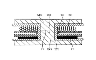
- FIG. 4 shows the fourth embodiment, and the portion connected by the conductive adhesive 71 in the central portion 62 of the ferrite cores 242 and 542 of the step-up transformer of the third embodiment shown in FIG. 3 is the ferrite core 243. , 543 are connected to each other by the conductive adhesive 71 in the central portion 63.
- FIG. 5 shows the fifth embodiment, in which the tip of the convex portion of the ferrite core 244 having a convex cross section and the disk-shaped or strip-shaped ferrite core 544 are connected by the conductive adhesive 71.
- the ferrite core 544 since the ferrite core 544 has a disk shape or a strip shape, there is an advantage that the molding can be made easier.
- the central portion 65 of the ferrite core 245 is inserted through the central hole of the insulating member 255, and the tip of the central portion 65 is connected to the center of the ferrite core 545 by the conductive adhesive 71.
- ferrite core 7 includes a ferrite core 246 having an E-shaped cross section and a ferrite core 546 having an E-shaped cross section.
- the center portions of the ferrite cores 246 and 546 are inserted through the center hole of the insulating member 255, and the tips of both center portions are connected by the conductive adhesive 71.
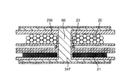
- Embodiment 8 In Embodiment 8 shown in FIG. 8, a bobbin-shaped integral ferrite core 247 is embedded in the bobbin-shaped insulating member 256 by insert molding or the like. There is no gap in the central portion 66 of the ferrite core 247.
- the ferrite core 247 is insulated by the insulating member 256 that seals the ferrite core 247, it is not necessary to perform grounding based on the requirements of safety standards and the like.
- the attachment process can be omitted.
- Embodiment 9 In the step-up transformer of Embodiment 9 shown in FIGS. 9 and 10, the upper end portion of the ferrite core 248 and the lower end portion of the ferrite core 548 are disposed in the center hole of the bobbin-shaped insulating member 252, and the core fixing band 27 The ferrite core 248 and the ferrite core 548 are pressed to bring the upper end portion and the lower end portion into contact with each other. Thereby, there is no gap between the upper end portion of the ferrite core 248 and the lower end portion of the ferrite core 548.
- the lower end 27a of the core fixing band 27 functions as a ground pin.
Landscapes
- Engineering & Computer Science (AREA)
- Power Engineering (AREA)
- Coils Of Transformers For General Uses (AREA)
Abstract
フェライトコアを小型、軽量化でき、かつ、1次巻線および2次巻線の巻数を低減して、全体を小型、軽量化できてコストダウンができる高周波加熱装置用昇圧変圧器を提供する。ボビン形状の絶縁部材(252)の中心孔に、フェライトコア(242,542)の端部(242c,542c)を配置し、この端部(242c,542c)の先端を導電性接着剤(71)によって互いに連結している。上記中心孔内に位置するフェライトコア2(42,542)の中央部(62)には、ギャップがない。1次巻線(20),2次巻線(21)の巻線幅(W1,W2)は、1次巻線(20),2次巻線(21)の重ね厚み(T1,T2)よりも小さくて、巻線形状は扁平になっている。
Description
この発明は、高周波加熱装置用昇圧変圧器に関する。
電子レンジのような高周波加熱装置においては、商用交流電源を整流した直流電圧をインバータ回路によって高周波電圧に変換し、この高周波電圧を高周波加熱装置用昇圧変圧器で昇圧してマグネトロンに供給するようにしている。
従来、この種の高周波加熱装置用昇圧変圧器としては、特許第3726010号公報(特許文献1)に記載のものがある。
この従来の高周波加熱装置用昇圧変圧器は、本願発明者等が発明したもので、大量に製造されており、好評を得ているものであり、中心孔を有するボビン形状の絶縁部材と、この絶縁部材の中心孔に挿入された中央部を有するフェライトコアと、上記絶縁部材に巻回され、その絶縁部材によって相互に絶縁される共に、巻線幅方向に互いに間隔をおいて対向するように、かつ、相互の結合係数が0.65~0.8になるように配された1次巻線および2次巻線とを備えている。そして、上記1次巻線および上記2次巻線のそれぞれの巻線幅が、上記1次巻線および上記2次巻線のそれぞれの重ね厚みより小さく、上記2次巻線が、分割されることなく1つのブロックとして形成されており、さらに、上記フェライトコアの中央部には、ギャップを設けている。
上記従来の高周波加熱装置用昇圧変圧器は、上述のように、1次巻線および2次巻線のそれぞれの巻線幅が、1次巻線および2次巻線のそれぞれの重ね厚みより小さくて、1次巻線および2次巻線の形状が扁平であって、小型であるため、高周波加熱装置(構造が複雑な上に高電圧線が配線されている)の内部に、容易に取り付けることができる上に、上記フェライトコアの中央部にギャップを設けているため、磁気飽和を防止できて、過電流、スイッチング素子の破壊を防止できるという優れた利点を有する。
しかしながら、上記従来の小型な高周波加熱装置用昇圧変圧器であっても、さらなる小型化とコストダウンをしなければならないという課題がある。特に、小型化、コストに大きく影響するコア、1次巻線および2次巻線の小型、軽量化に対する強い要請がある。
そこで、本願発明者は、鋭意、特にコアの小型化、巻線の巻数の低減を検討した。高周波加熱装置では、優れた高周波特性と耐熱性が要求されるため、現在のフェライトコアを他の材料に代えることができない。現在のフェライトコアを珪素鋼板等の鉄系コア材料に代えると、鉄損が大きくなって高周波特性が悪くなり、また、メタルコンポジット材(金属磁性粉末と樹脂を混ぜて成形したもの)に代えると、耐熱性が悪くなるため、フェライトコアのままで、小型化することが必要である。
そこで、本願発明者は、フェライトコアにおいては、フェライトコアの中央部に、磁気飽和を防止するために、当然にギャップを設けることが必須であるという当業者の常識を疑って、万に一つの可能性を考えて、上記従来の高周波加熱装置用昇圧変圧器のフェライトコアの中央部を連結して、ギャップを無くして、試みた。そうすると、当業者の予想に反して、磁気飽和が生じないことを発見した。
その詳細な理由は、定かではないが、次のように、考えられる。図11の模式図に示すように、巻線501,502を扁平にすると、巻線501,502の互いに対向する面積が大きくなって、コア511,512を通らずに、巻線501,502間で直接結合する矢印DFで示す磁束が増えると考えられる。その結果、コア511,512を通る磁束の量が減少して、磁気飽和限界が高くなったと考えられる。なお、520は、一般的に考えられている磁路を示し、LFは漏れ磁束を示している。
上記理由によって、本願発明者等による扁平な構成の高周波加熱装置用昇圧変圧器によると、磁気飽和限界が非常に高くなっているため、ギャップが無くても、磁気飽和に至らなかったのであると考えられる。
この発明の高周波加熱装置用昇圧変圧器は、上記発見に基づいてなされたもので、
中心孔を有するボビン形状の絶縁部材と、
上記絶縁部材の中心孔内に配置された中央部を有するフェライトコアと、
上記絶縁部材に巻回され、その絶縁部材によって相互に絶縁される共に、巻線幅方向に互いに間隔をおいて対向するように、かつ、相互の結合係数が0.65~0.8になるように配された1次巻線および2次巻線と
を備え、
上記1次巻線および上記2次巻線のそれぞれの巻線幅が、上記1次巻線および上記2次巻線のそれぞれの重ね厚みより小さく、
上記2次巻線が、分割されることなく1つのブロックとして形成されており、
上記フェライトコアの中央部は連結していてギャップが無い
ことを特徴としている。
中心孔を有するボビン形状の絶縁部材と、
上記絶縁部材の中心孔内に配置された中央部を有するフェライトコアと、
上記絶縁部材に巻回され、その絶縁部材によって相互に絶縁される共に、巻線幅方向に互いに間隔をおいて対向するように、かつ、相互の結合係数が0.65~0.8になるように配された1次巻線および2次巻線と
を備え、
上記1次巻線および上記2次巻線のそれぞれの巻線幅が、上記1次巻線および上記2次巻線のそれぞれの重ね厚みより小さく、
上記2次巻線が、分割されることなく1つのブロックとして形成されており、
上記フェライトコアの中央部は連結していてギャップが無い
ことを特徴としている。
上記構成の高周波加熱装置用昇圧変圧器によれば、上記フェライトコアの中央部にギャップが無いから、ギャップがあるものに比べて、インダクタンス値が上がり、したがって、1次巻線および2次巻線の巻数を低減して、小型、軽量化およびコストダウンを達成できる。
また、上記フェライトコアの中央部にギャップがある上記従来の高周波加熱装置用昇圧変圧器と、1次巻線および2次巻線の巻数を同じにした場合、この発明では、上記フェライトコアの中央部にギャップが無いから、フェライトコアの径を小さくしても、インダクタンス値を確保できて、フェライトコアを小型、軽量化できて、生産効率を向上でき、コストダウンを達成できる。
1実施形態では、
上記フェライトコアの中央部のうちの隣接する2つの部分は、導電性接着剤で接続されている。
上記フェライトコアの中央部のうちの隣接する2つの部分は、導電性接着剤で接続されている。
上記実施形態によれば、上記フェライトコアの中央部のうちの隣接する2つの部分は、導電性接着剤で接続されているから、中央部にギャップの無い一体構造のフェライトコアを、簡単、安価に製造できる。
1実施形態では、
上記フェライトコアの中央部のうちの隣接する2つの部分は、互いに当接している。
上記フェライトコアの中央部のうちの隣接する2つの部分は、互いに当接している。
上記実施形態によれば、上記フェライトコアの中央部のうちの隣接する2つの部分は、互いに当接しているから、簡単、安価に、中央部にギャップの無いフェライトコアを、簡単、安価に製造できる。
1実施形態では、
上記フェライトコアは、インサート成形によって上記絶縁部材の中に埋め込まれている。
上記フェライトコアは、インサート成形によって上記絶縁部材の中に埋め込まれている。
上記実施形態によれば、上記フェライトコアは、インサート成形によって上記絶縁部材の中に埋め込まれているから、上記フェライトコアと上記絶縁部材が一体化されていて、取り扱いが容易になり、かつ、絶縁のための安全規格等の制約を受けなくすることができる。
この発明によれば、1次巻線および2次巻線が扁平で、磁気飽和を防止できる上に、ボビン形状の絶縁部材の中心孔に配置されたフェライトコアの中央部にギャップが無いから、インダクタンス値が上がって、フェライトコアを小型、軽量化でき、かつ、1次巻線および2次巻線の巻数を低減して、小型、軽量化でき、コストダウンを達成できる。
以下、この発明を図示の実施形態により詳細に説明する。
(実施形態1)
図1はこの発明の実施形態1の高周波加熱装置用昇圧変圧器の構造を示している。この昇圧変圧器は、図1に示すように、巻線は、1次巻線20,2次巻線21およびフィラメント巻線23によって構成され、ボビン形状の絶縁部材25に、絶縁部材25の分割壁により互いに絶縁された状態で、巻回されている。
図1はこの発明の実施形態1の高周波加熱装置用昇圧変圧器の構造を示している。この昇圧変圧器は、図1に示すように、巻線は、1次巻線20,2次巻線21およびフィラメント巻線23によって構成され、ボビン形状の絶縁部材25に、絶縁部材25の分割壁により互いに絶縁された状態で、巻回されている。
この1次巻線20,2次巻線21を結合させるための磁性体として、2個のU字形のフェライトコア24,54の中央部となる部分24c,54cが、絶縁部材25の中心孔25c内に配置されている。上記部分24c,54cの先端は、導電性接着剤71によって互いに接続されて、上記フェライトコア24,54は一体構造になっている。上記部分24c,54cは、一体構造のフェライトコア24,54の中央部60を構成し、この中央部60は、絶縁部材25の中心孔25c内に位置する。上記部分24c,54cは、中央部60のうちの互いに隣接する部分24c,54cであって、導電性接着剤71によって互いに連結されていて、中央部60には、ギャップが無い。
上記1次巻線20の巻線幅W1は、1次巻線20の重ね厚みT1よりも小さくて、1次巻線20の巻線形状としては扁平になっている。つまり、1次巻線20は、W1<T1として、好ましくは、T1の値がW1の値の1.2~9倍、好ましくは1.5~9倍になるようにしている。上記2次巻線21の巻線幅W2と重ね厚みT2についても、1次巻線21と同様のW2<T2の関係となっている。
上記2次巻線21においては、巻線幅W2を重ね厚みT2よりも短くしたことにより、従来のように2次巻線を絶縁部材で2~3ブロックに分割する必要が無くなって、巻線を落ち込みにくくすることができる。その結果、昇圧変圧器の巻線形成工程における巻線の段落ちに起因して生じる絶縁破壊、つまり、段落ちした巻線に高電圧が印加されることによって生じる巻線の絶縁破壊を防止することができる。
また、この実施形態1では、上記2次巻線21は、分割されることなく1つのブロックになっていて、上記絶縁部材25の分割壁のうち、2次巻線21を複数に分割する分割壁が無いから、その分だけ昇圧変圧器の高さHを低くできる。すなわち、図1の昇圧変圧器は、巻線の総断面積を変えることなく、その高さHが低くなっている。なお、上記絶縁部材25は、1次巻線20および2次巻線21をそれぞれ収納する2つの空間と、これら2つの空間によって挟まれる位置に、上記2つの空間とは分割壁を隔てて形成される他の空間とを構成している。なお、26は1次、2次巻線20,21とコア24,54との間の絶縁を確保するための絶縁材である。
また、上記1次巻線20および2次巻線21の重ね厚みT1,T2が巻線幅W1,W2よりも大きくしているため、昇圧変圧器の高さ方向に配列されている1次巻線20および2次巻線21間の対向する面積が増加している。その結果、コア24,54を介さずに、1次、2次巻線20,21相互間での直接結合を大きくすることができ、コア24,54を通る磁束量を低減できる。また、上記1次巻線20および2次巻線21の相互の結合係数は、0.65~0.8としている。
この実施形態1の高周波加熱装置用昇圧変圧器によれば、上記フェライトコア24,54の中央部60にギャップが無くても、磁気飽和が起こらないことが確認された。その理由としては、概念的には、次のように、考えられる。図11の模式図に示すように、巻線501,502を扁平にすると、巻線501,502の互いに対向する面積が大きくなって、コア511,512を通らずに、巻線501,502間で直接結合する矢印DFで示す磁束が増えると考えられる。その結果、コア511,512を通る磁束の量が減少して、磁気飽和限界が高くなったと考えられる。
また、上記フェライトコア24,54の中央部60にギャップが無いから、ギャップがあるものに比べて、インダクタンス値が上がり、したがって、1次巻線20および2次巻線21の巻数を低減して、小型、軽量化およびコストダウンを達成できる。特に、1次巻線20および2次巻線21の材料である銅線は高価であり、かつ、重量が大きいから、巻数を低減することにより、コストダウンの大きな効果が得られ、軽量化の大きな効果が得られる。
また、フェライトコアの中央部にギャップがある上記従来の高周波加熱装置用昇圧変圧器の1次巻線および2次巻線と、この実施形態の1次巻線20および2次巻線21の巻数を同じにした場合、この発明では、上記フェライトコア24,54の中央部60にギャップが無いから、フェライトコアの24,54の中央部60の径を小さくしても、インダクタンス値を確保できて、フェライトコア24,54を小型、軽量化できて、生産効率を向上でき、コストダウンを達成できる。
(実施形態2)
図2に、この発明の実施形態2の昇圧変圧器の構造を示す。図2において、図1に示された実施形態1の構成要素と同一構成要素については、図1の構成要素と同一の参照番号を付して、詳しい説明は省略する。
図2に、この発明の実施形態2の昇圧変圧器の構造を示す。図2において、図1に示された実施形態1の構成要素と同一構成要素については、図1の構成要素と同一の参照番号を付して、詳しい説明は省略する。
図2に示すように、ボビン形状の絶縁部材251の中心孔251cには、フェライトコア241,541の端部241c,541cを配置し、この端部241c,541cの先端を導電性接着剤71によって互いに連結している。したがって、上記互いに連結された端部241c,541cからなるフェライトコア241,541の中央部61には、ギャップが無い。
この実施形態2においては、1次巻線20および2次巻線21を偏平にしたことによって、図2に示す矢印E部のフェライトコア241,541の磁気的な結合度合いが高くなっていることを利用して、フェライトコア241,541の腕から、絶縁部材251の外周部、すなわち、巻線が施された溝部の開放端への回り込みをなくしている。これにより、実施形態1における絶縁部材26を不要とした上に、巻線を巻く前にフェライトコア241,541を絶縁部材251へ取り付けることができる。
なお、上記絶縁部材251の内壁には、接地用の板ばね28を設けている。
この実施形態2の高周波加熱装置用昇圧変圧器によれば、上記フェライトコア241,541の中央部61にギャップが無くても、磁気飽和が起こりにくいことが確認された。
また、上記フェライトコア241,541の中央部61にギャップが無いから、ギャップがあるものに比べて、インダクタンス値が上がり、したがって、1次巻線20および2次巻線21の巻数を低減して、小型、軽量化およびコストダウンを達成できる。
また、フェライトコアの中央部にギャップがある上記従来の高周波加熱装置用昇圧変圧器の1次巻線および2次巻線と、この実施形態の1次巻線20および2次巻線21の巻数を同じにした場合、この実施形態2では、上記フェライトコア241,541の中央部61にギャップが無いから、フェライトコアの241,541の中央部61の径を小さくしても、インダクタンス値を確保できて、フェライトコア241,541を小型、軽量化できて、生産効率を向上でき、コストダウンを達成できる。
さらに、上記フェライトコアの241,541の中央部61にギャップが無いから、漏れ磁束の発生を防止できる。
(実施形態3)
図3は、この発明の実施形態3の昇圧変圧器の断面図である。図3において、図1,2に示された実施形態1および2の構成要素と同一構成要素については、図1,2の構成要素と同一の参照番号を付して、詳しい説明は省略する。以下、同様。
図3は、この発明の実施形態3の昇圧変圧器の断面図である。図3において、図1,2に示された実施形態1および2の構成要素と同一構成要素については、図1,2の構成要素と同一の参照番号を付して、詳しい説明は省略する。以下、同様。
図3に示すように、ボビン形状の絶縁部材252の中心孔には、フェライトコア242,542の端部242c,542cを配置し、この端部242c,542cの先端を導電性接着剤71によって互いに連結している。したがって、上記互いに連結された端部242c,542cからなるフェライトコア242,542の中央部62には、ギャップが無い。
このように、上記フェライトコア242,542の中央部62にギャップが無いから、ギャップがあるものに比べて、インダクタンス値が上がり、したがって、1次巻線20および2次巻線21の巻数を低減して、小型、軽量化およびコストダウンを達成できる。
さらに、図2と図3との対比からも明らかなように、この実施形態3では、フェライトコア242,542の腕部242a,542aは、放射状または円板状になっていて、腕部242a,542aの肉厚は、実施形態2の場合に比べて薄くなっている。そのため、昇圧変圧器の高さHをより低くできる上に、巻線を巻く前にフェライトコア242,542を取り付けた場合に、巻線時の回転モーメントを安定させることができ、その結果、巻線の巻乱れが生じにくくなるという利点がある。
(実施形態4~7)
図4は、実施形態4を示し、図3に示した実施形態3の昇圧変圧器のフェライトコア242,542の中央部62の導電性接着剤71によって連結されている箇所とは、フェライトコア243,543の中央部63の導電性接着剤71によって連結されている箇所が異なるものである。
図4は、実施形態4を示し、図3に示した実施形態3の昇圧変圧器のフェライトコア242,542の中央部62の導電性接着剤71によって連結されている箇所とは、フェライトコア243,543の中央部63の導電性接着剤71によって連結されている箇所が異なるものである。
また、図5は、実施形態5を示し、断面凸形状のフェライトコア244の凸部の先端と円板状または短冊状のフェライトコア544とを導電性接着剤71によって連結している。この実施形態5では、フェライトコア544が円板状または短冊状であるから、その成形をより容易にすることができるという利点がある。
図6に示す実施形態6は、断面がE字形状のフェライトコア245と、円板状または短冊状のフェライトコア545を有する。上記フェライトコア245の中央部65は、絶縁部材255の中心孔に挿通し、その中央部65の先端をフェライトコア545の中心に導電性接着剤71によって連結している。
図7に示す実施形態7は、断面がE字形状のフェライトコア246と、断面がE字形状のフェライトコア546を有する。上記フェライトコア246,546の中央部を、絶縁部材255の中心孔に挿通し、両中央部の先端を導電性接着剤71によって連結している。
(実施形態8)
図8に示す実施形態8では、ボビン形状の絶縁部材256の内部に、ボビン形状の一体のフェライトコア247をインサート成形等により埋め込んでいる。上記フェライトコア247の中央部66には、ギャップが無い。
図8に示す実施形態8では、ボビン形状の絶縁部材256の内部に、ボビン形状の一体のフェライトコア247をインサート成形等により埋め込んでいる。上記フェライトコア247の中央部66には、ギャップが無い。
この実施形態8では、フェライトコア247が、そのフェライトコア247を封止している絶縁部材256によって絶縁されているから、安全規格等の要求に基づく接地を行なう必要がなくなると共に、フェライトコア247の取り付け工程を省略することができる。
(実施形態9)
図9および10に示す実施形態9の昇圧変圧器は、ボビン形状の絶縁部材252の中心孔に、フェライトコア248の上端部とフェライトコア548の下端部とを配置し、コア固定バンド27によって、フェライトコア248とフェライトコア548とを押圧して、この上端部と下端部とを互いに当接させている。これにより、フェライトコア248の上端部とフェライトコア548の下端部との間に、ギャップが無いようにしている。
図9および10に示す実施形態9の昇圧変圧器は、ボビン形状の絶縁部材252の中心孔に、フェライトコア248の上端部とフェライトコア548の下端部とを配置し、コア固定バンド27によって、フェライトコア248とフェライトコア548とを押圧して、この上端部と下端部とを互いに当接させている。これにより、フェライトコア248の上端部とフェライトコア548の下端部との間に、ギャップが無いようにしている。
なお、上記コア固定バンド27の下側の端部27aが接地ピンとして機能している。
20 1次巻線
21 2次巻線
24,54,241,541,242,542,243,543,244,544,246,546,247,248,548 フェライトコア
25,251,252,255,256 絶縁部材
60,61,62,63,64,65,66 中央部
71 導電性接着剤
T1 1次巻線の重ね厚み
T2 2次巻線の重ね厚み
W1 1次巻線の巻線幅
W2 2次巻線の巻線幅
21 2次巻線
24,54,241,541,242,542,243,543,244,544,246,546,247,248,548 フェライトコア
25,251,252,255,256 絶縁部材
60,61,62,63,64,65,66 中央部
71 導電性接着剤
T1 1次巻線の重ね厚み
T2 2次巻線の重ね厚み
W1 1次巻線の巻線幅
W2 2次巻線の巻線幅
Claims (4)
- 中心孔を有するボビン形状の絶縁部材(25,251,252,255,256)と、
上記絶縁部材(25,251,252,255,256)の中心孔内に配置された中央部(60,61,62,63,64,65,66)を有するフェライトコア(24,54,241,541,242,542,243,543,244,544,246,546,247,248,548)と、
上記絶縁部材(25,251,252,255,256)に巻回され、その絶縁部材(25,251,252,255,256)によって相互に絶縁される共に、巻線幅(W1,W2)方向に互いに間隔をおいて対向するように、かつ、相互の結合係数が0.65~0.8になるように配された1次巻線(20)および2次巻線(21)と
を備え、
上記1次巻線(20)および上記2次巻線(21)のそれぞれの巻線幅(W1,W2)が、上記1次巻線(20)および上記2次巻線(21)のそれぞれの重ね厚み(T1,T2)より小さく、
上記2次巻線(21)が、分割されることなく1つのブロックとして形成されており、
上記フェライトコア(24,54,241,541,242,542,243,543,244,544,246,546,247,248,548)の中央部(60,61,62,63,64,65,66)は連結されていてギャップが無い
ことを特徴とする高周波加熱装置用昇圧変圧器。 - 請求項1に記載の高周波加熱装置用昇圧変圧器において、
上記フェライトコア(24,54,241,541,242,542,243,543,244,544,246,546)の中央部(60,61,62,63,64,65)のうちの隣接する2つの部分は、導電性接着剤(71)で接続されていることを特徴とする高周波加熱装置用昇圧変圧器。 - 請求項1に記載の高周波加熱装置用昇圧変圧器において、
上記フェライトコア(248,548)の中央部のうちの隣接する2つの部分は、互いに当接していることを特徴とする高周波加熱装置用昇圧変圧器。 - 請求項1から3のいずれか1つに記載の高周波加熱装置用昇圧変圧器において、
上記フェライトコア(247)は、インサート成形によって上記絶縁部材(256)の中に埋め込まれていることを特徴とする高周波加熱装置用昇圧変圧器。
Applications Claiming Priority (2)
| Application Number | Priority Date | Filing Date | Title |
|---|---|---|---|
| JP2011289256A JP2013138151A (ja) | 2011-12-28 | 2011-12-28 | 高周波加熱装置用昇圧変圧器 |
| JP2011-289256 | 2011-12-28 |
Publications (1)
| Publication Number | Publication Date |
|---|---|
| WO2013099622A1 true WO2013099622A1 (ja) | 2013-07-04 |
Family
ID=48697114
Family Applications (1)
| Application Number | Title | Priority Date | Filing Date |
|---|---|---|---|
| PCT/JP2012/082302 Ceased WO2013099622A1 (ja) | 2011-12-28 | 2012-12-13 | 高周波加熱装置用昇圧変圧器 |
Country Status (2)
| Country | Link |
|---|---|
| JP (1) | JP2013138151A (ja) |
| WO (1) | WO2013099622A1 (ja) |
Cited By (1)
| Publication number | Priority date | Publication date | Assignee | Title |
|---|---|---|---|---|
| CN104934195A (zh) * | 2014-03-19 | 2015-09-23 | 胜美达集团有限公司 | 铁磁材料的芯体、用于电感部件的磁芯和形成磁芯的方法 |
Families Citing this family (1)
| Publication number | Priority date | Publication date | Assignee | Title |
|---|---|---|---|---|
| CN119381138B (zh) * | 2024-11-04 | 2025-08-19 | 深圳市鑫海鹰电子科技有限公司 | 一种模块化组合式高频开关变压器 |
Citations (5)
| Publication number | Priority date | Publication date | Assignee | Title |
|---|---|---|---|---|
| JP2002134266A (ja) * | 2000-10-24 | 2002-05-10 | Sharp Corp | 高周波加熱装置 |
| JP2003086431A (ja) * | 2001-06-29 | 2003-03-20 | Tabuchi Electric Co Ltd | 電磁誘導器 |
| JP2004111528A (ja) * | 2002-09-17 | 2004-04-08 | Matsushita Electric Ind Co Ltd | マグネトロン駆動用昇圧トランス |
| JP2005057150A (ja) * | 2003-08-07 | 2005-03-03 | Tabuchi Electric Co Ltd | 薄型電磁誘導器 |
| JP3726010B2 (ja) * | 1999-06-03 | 2005-12-14 | シャープ株式会社 | 高周波加熱装置用昇圧変圧器 |
-
2011
- 2011-12-28 JP JP2011289256A patent/JP2013138151A/ja active Pending
-
2012
- 2012-12-13 WO PCT/JP2012/082302 patent/WO2013099622A1/ja not_active Ceased
Patent Citations (5)
| Publication number | Priority date | Publication date | Assignee | Title |
|---|---|---|---|---|
| JP3726010B2 (ja) * | 1999-06-03 | 2005-12-14 | シャープ株式会社 | 高周波加熱装置用昇圧変圧器 |
| JP2002134266A (ja) * | 2000-10-24 | 2002-05-10 | Sharp Corp | 高周波加熱装置 |
| JP2003086431A (ja) * | 2001-06-29 | 2003-03-20 | Tabuchi Electric Co Ltd | 電磁誘導器 |
| JP2004111528A (ja) * | 2002-09-17 | 2004-04-08 | Matsushita Electric Ind Co Ltd | マグネトロン駆動用昇圧トランス |
| JP2005057150A (ja) * | 2003-08-07 | 2005-03-03 | Tabuchi Electric Co Ltd | 薄型電磁誘導器 |
Cited By (4)
| Publication number | Priority date | Publication date | Assignee | Title |
|---|---|---|---|---|
| CN104934195A (zh) * | 2014-03-19 | 2015-09-23 | 胜美达集团有限公司 | 铁磁材料的芯体、用于电感部件的磁芯和形成磁芯的方法 |
| EP2933806A3 (de) * | 2014-03-19 | 2015-11-18 | SUMIDA Components & Modules GmbH | Kernkörper aus ferromagnetischem Material, Magnetkern für ein induktives Bauteil und Verfahren zum Herstellen eines Magnetkerns |
| US9620277B2 (en) | 2014-03-19 | 2017-04-11 | SUMIDA Components & Modules GmbH | Core body of ferromagnetic material, magnetic core for an inductive component and method of forming a magnetic core |
| CN104934195B (zh) * | 2014-03-19 | 2017-06-23 | 胜美达集团有限公司 | 铁磁材料的芯体、用于电感部件的磁芯和形成磁芯的方法 |
Also Published As
| Publication number | Publication date |
|---|---|
| JP2013138151A (ja) | 2013-07-11 |
Similar Documents
| Publication | Publication Date | Title |
|---|---|---|
| EP0977214B1 (en) | Amorphous metal core transformer | |
| US9640307B2 (en) | Transformer | |
| US12198849B2 (en) | Method for manufacturing a transformer | |
| CN102947903B (zh) | 电抗器 | |
| US20190019613A1 (en) | Hollow toroidal magnetic power unit | |
| KR20120052339A (ko) | 고전류 자기소자 및 그 제조방법 | |
| US12614661B2 (en) | Transformer and flat panel display device including same | |
| CN109767892B (zh) | 扼流圈 | |
| JP2001267153A (ja) | 電源トランス | |
| EP3026683A1 (en) | Transformer, power supply device, and method for manufacturing transformer | |
| JP2013501369A (ja) | 電流補償チョークおよび電流補償チョークの製造方法 | |
| US20150109081A1 (en) | Cast coil assembly with fins for an electrical transformer | |
| US7221252B1 (en) | Transformer | |
| JP2012023090A (ja) | リアクトル | |
| US6861938B2 (en) | High-frequency power inductance element | |
| JPH11144971A (ja) | コイル部品およびそれを用いた電源装置 | |
| WO2013099622A1 (ja) | 高周波加熱装置用昇圧変圧器 | |
| KR101932232B1 (ko) | 전원공급장치의 트랜스포머용 분리형 보빈 구조 | |
| JP2025160377A (ja) | リーケージトランス | |
| JP7548407B2 (ja) | 絶縁トランス | |
| EP2996122A1 (en) | Transformer | |
| JP7029920B2 (ja) | 変圧器 | |
| KR100388604B1 (ko) | 타원형 타권 핼리시스로 권선된 평각 코일을 갖는 리액터 및 이의 제조 방법 | |
| RU104376U1 (ru) | Силовой импульсный трансформатор | |
| KR101130790B1 (ko) | 변압기 및 그 제조방법 |
Legal Events
| Date | Code | Title | Description |
|---|---|---|---|
| 121 | Ep: the epo has been informed by wipo that ep was designated in this application |
Ref document number: 12862180 Country of ref document: EP Kind code of ref document: A1 |
|
| NENP | Non-entry into the national phase |
Ref country code: DE |
|
| 122 | Ep: pct application non-entry in european phase |
Ref document number: 12862180 Country of ref document: EP Kind code of ref document: A1 |