WO2013099591A1 - 測定装置 - Google Patents
測定装置 Download PDFInfo
- Publication number
- WO2013099591A1 WO2013099591A1 PCT/JP2012/082083 JP2012082083W WO2013099591A1 WO 2013099591 A1 WO2013099591 A1 WO 2013099591A1 JP 2012082083 W JP2012082083 W JP 2012082083W WO 2013099591 A1 WO2013099591 A1 WO 2013099591A1
- Authority
- WO
- WIPO (PCT)
- Prior art keywords
- contact
- living body
- excitation light
- contact portion
- probe
- Prior art date
- Legal status (The legal status is an assumption and is not a legal conclusion. Google has not performed a legal analysis and makes no representation as to the accuracy of the status listed.)
- Ceased
Links
Images






Classifications
-
- A—HUMAN NECESSITIES
- A61—MEDICAL OR VETERINARY SCIENCE; HYGIENE
- A61B—DIAGNOSIS; SURGERY; IDENTIFICATION
- A61B5/00—Measuring for diagnostic purposes; Identification of persons
- A61B5/0059—Measuring for diagnostic purposes; Identification of persons using light, e.g. diagnosis by transillumination, diascopy, fluorescence
- A61B5/0071—Measuring for diagnostic purposes; Identification of persons using light, e.g. diagnosis by transillumination, diascopy, fluorescence by measuring fluorescence emission
-
- G—PHYSICS
- G01—MEASURING; TESTING
- G01N—INVESTIGATING OR ANALYSING MATERIALS BY DETERMINING THEIR CHEMICAL OR PHYSICAL PROPERTIES
- G01N21/00—Investigating or analysing materials by the use of optical means, i.e. using sub-millimetre waves, infrared, visible or ultraviolet light
- G01N21/62—Systems in which the material investigated is excited whereby it emits light or causes a change in wavelength of the incident light
- G01N21/63—Systems in which the material investigated is excited whereby it emits light or causes a change in wavelength of the incident light optically excited
- G01N21/64—Fluorescence; Phosphorescence
- G01N21/645—Specially adapted constructive features of fluorimeters
-
- G—PHYSICS
- G01—MEASURING; TESTING
- G01N—INVESTIGATING OR ANALYSING MATERIALS BY DETERMINING THEIR CHEMICAL OR PHYSICAL PROPERTIES
- G01N21/00—Investigating or analysing materials by the use of optical means, i.e. using sub-millimetre waves, infrared, visible or ultraviolet light
- G01N21/62—Systems in which the material investigated is excited whereby it emits light or causes a change in wavelength of the incident light
- G01N21/63—Systems in which the material investigated is excited whereby it emits light or causes a change in wavelength of the incident light optically excited
- G01N21/64—Fluorescence; Phosphorescence
- G01N21/645—Specially adapted constructive features of fluorimeters
- G01N2021/6484—Optical fibres
Definitions
- the present invention relates to a measuring apparatus for measuring the skin condition.
- AGEs Advanced Glycation End Products
- AGEs are final products formed by a non-enzymatic sugar addition reaction (Maillard reaction) between proteins and carbohydrates or lipids, exhibiting a yellowish brown color, and some of them are fluorescent substances.
- AGEs have a property of forming a crosslink by binding to a nearby structural protein.
- cross-linking between AGEs and collagen constituting the dermis lowers the elasticity of the skin, and also causes problems such as wrinkles and dullness. Therefore, it is possible to evaluate skin health and aging by monitoring AGEs.
- An apparatus capable of accurately evaluating the amount of AGEs accumulated in the skin is useful as a means for allowing the user to recognize the need for care using a commercially available cream or the like that reduces AGEs.
- Patent Document 1 discloses an apparatus for measuring a skin condition by irradiating skin with excitation light emitted from at least one light source and using fluorescence reflected from the skin as a parameter.
- the excitation light is preferably irradiated perpendicular to the skin surface.
- Patent Document 1 when the excitation light is irradiated onto the skin surface, if the probe is brought into contact with the skin surface by tilting, There arises a problem that the excitation light is irradiated at the same angle.
- the present invention has been made in view of the above problems, and even when the user tilts the probe and contacts the skin surface, the probe is tilted and is in contact with the skin surface. It is to provide a measuring apparatus that can correct the inclination of the probe by itself and improve the reproducibility of the measurement.
- a measurement apparatus is a measurement apparatus including an irradiation unit that irradiates a living body with excitation light guided from an excitation light source, and a light receiving unit that receives fluorescence generated by irradiation of the excitation light.
- a first contact portion that holds the irradiating portion and contacts the living body, and a second contact portion that contacts the living body in substantially the same plane as the contact surface where the first contact section contacts the living body. It is what you have.
- the measurement apparatus according to the present invention can be appropriately irradiated with excitation light by being configured as described above, and can improve the reproducibility of measurement.
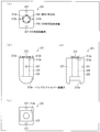
- FIG. 1A is a diagram of a configuration of a probe mounted on an embodiment of the present invention as viewed from the front
- FIG. 1B is a diagram of the probe as viewed from above
- FIG. 2 is a diagram showing a configuration of a measuring apparatus according to an embodiment of the present invention.
- 3A, FIG. 3B, and FIG. 3C are diagrams showing another configuration example of the protrusion structure shown in FIG.
- FIG. 3D is a diagram showing a configuration when a raised structure, which is an alternative configuration of the protruding structure, is provided at the probe tip.
- FIG. 4 is a view showing a cross-sectional view of the bundle fiber inserted into the bundle fiber passage hole of the probe.
- FIG. 4 is a view showing a cross-sectional view of the bundle fiber inserted into the bundle fiber passage hole of the probe.
- FIG. 5A is a diagram illustrating a configuration in which a contact electrode is disposed in a protruding structure when viewed from the front of the probe.
- FIG. 5B is a diagram showing a configuration when the contact electrode is arranged on the protruding structure as viewed from above the probe. It is a figure which shows the structure of the electric circuit connected to the contact electrode shown by (b) of FIG.
- FIG. 6 is a flow chart illustrating a process for determining that the probe is in proper contact with the skin surface.
- FIG. It is a longitudinal cross-sectional view of a probe which shows when a movable mechanism is arrange
- FIG. 9A is a view of the X direction movable portion as viewed from above
- FIG. 9B is a view of the X direction movable portion as viewed from the front
- FIG. 9C is a view of the X direction movable portion. It is the figure seen from the lower part
- (d) of Drawing 9 is a figure which looked at the X direction movable part from the side.
- 10A is a view of the Y-direction movable portion provided on the probe of FIG. 8 as viewed from above
- FIG. 10B is a view of the Y-direction movable portion as viewed from the front.
- (C) is the figure which looked at the Y direction movable part from the lower part, (d) of FIG.
- FIG. 10 is the figure which looked at the Y direction movable part from the side. It is a longitudinal cross-sectional view which shows the probe handle part provided in the probe of FIG. 12A is a longitudinal sectional view showing the probe when the Z-direction movable portion is attached, and FIG. 12B is an X-direction movable portion and the Y-direction when the Z-direction movable portion is attached. It is the figure which looked at the movable part from the side.
- FIGS. 1 to 12 Embodiments of the present invention will be described with reference to FIGS. 1 to 12 as follows.
- the measuring apparatus is a late saccharification reaction that occurs in the skin by bringing the tip of the probe into contact with the human skin surface, irradiating the skin surface with excitation light, and receiving fluorescence generated by the irradiated excitation light. It is an apparatus for measuring sex organisms (hereinafter referred to as AGEs).
- the excitation light is preferably irradiated perpendicularly to the skin surface. This is because the AGEs to be measured by the present invention are accumulated not only on the surface of the skin but also inside the skin, reducing the loss of excitation light as much as possible and irradiating the deep part of the skin with the excitation light. Because it is necessary to do.
- An object of the present invention is to realize an apparatus that can easily irradiate excitation light perpendicularly to the skin surface.
- the present invention includes a first contact unit that holds an irradiation unit that irradiates a living body with excitation light and that contacts the living body; By providing the second contact portion in contact with the user, the user is informed that the probe cannot be brought into contact with the skin surface vertically, so that the user can bring the probe into contact with the skin surface vertically. It is a measuring device that can be corrected.
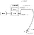
- FIG. 2 is a diagram showing a configuration of the measuring apparatus 1 according to an embodiment of the present invention.
- the measuring device 1 includes a measuring device main body 2, a bundle fiber 3, and a probe 4.
- the measuring device main body 2 includes an excitation light source 5 and a spectrometer 6.
- An excitation-side optical fiber (irradiation unit) 7 bundled with a bundle fiber 3 is connected to the excitation light source 5, and a light-receiving side optical fiber (light-receiving unit) 8 is connected to the spectrometer 6.
- the tip of the bundle fiber 3 opposite to the measuring device main body 2 is connected to the probe 4.
- the excitation light generated by the excitation light source 5 is in a wavelength range suitable for measuring AGEs.
- the excitation light generated from the excitation light source 5 preferably has a wavelength of 315 to 400 nm, which is the UVA region. AGEs can be appropriately measured by using light having a wavelength in the region as excitation light.
- the spectrometer 6 detects and analyzes the fluorescence guided by the light receiving side optical fiber 8.
- the analyzed result is transmitted to the display unit 9.
- the display unit 9 may be anything as long as it can display an image. Examples thereof include a dedicated liquid crystal display device, a CRT, a personal computer, a television, and the like.
- FIG. 1A is a diagram of the configuration of the probe 4 mounted on the measuring apparatus 1 as viewed from the front
- FIG. 1B is a diagram of the probe 4 as viewed from above.
- the probe 4 includes a probe handle portion 10 (probe main body portion) and a probe tip portion 11.
- a contact plane 12 is disposed on the side of the probe tip 11 that contacts the skin surface.
- a bundle fiber passage hole 13 for inserting the bundle fiber 3 is formed at the center of the probe handle 10. The bundle fiber passage hole 13 is formed in the probe 4 so as to penetrate from the contact plane 12 to the opposite side.
- the contact plane 12 includes a contact portion (first contact portion) 14 and a protrusion structure (second contact portion) 15.
- the contact portion 14 is to be brought into contact with the skin surface and is arranged at the center of the probe tip portion 11.
- the protrusion structure 15 protrudes from the probe tip 11 so that the contact portion 14 contacts the skin surface in substantially the same plane as the contact surface that contacts the skin surface.
- the protrusion structure 15 is arranged at four locations around the contact portion 14.
- the four protrusion structures 15 may be arranged at equal intervals from the center of the contact portion 14 on the circumference of a radius having an arbitrarily determined length. There may be a height difference of about 1 mm between the surface of the contact portion 14 that contacts the skin surface and the tip of the protruding structure 15 that contacts the skin surface.
- the contact portion 14 is appropriately in contact with the skin surface when all four portions are in contact with the skin surface. Whether or not all the protrusion structures 15 are in contact with the skin surface is determined by the user himself / herself with the sense of skin. If the user himself / herself feels that only two of the four protrusion structures 15 are in contact with each other, the user himself / herself needs to make corrections by moving the probe 4 so that the user feels that all four locations are in contact. There is.
- the protrusion structures 15 are arranged on a circumference having a radius of about 1 cm from the center of the contact portion 14. It is preferable. This is because, although there are individual differences as to whether or not the protruding structures 15 have all contacted the skin, most users can recognize that the protruding structures 15 are in contact with each other if the protruding structures 15 are located about 1 cm away from the center of the contact portion 14. This is because it is assumed.
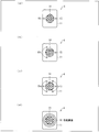
- FIGS. 3A, 3 ⁇ / b> B, and 3 ⁇ / b> C are diagrams illustrating another configuration example of the protrusion structure 15.
- FIG. 3D is a diagram showing a configuration when a raised structure 16 (details will be described later), which is an alternative configuration of the protruding structure 15, is provided on the probe tip 11.
- two protrusion structures 15 may be arranged on the probe tip 11.
- the probe tip portion 11 may be provided with three protruding structures 15, or as shown in FIG. 3C, six protruding structures. 15 may be arranged.
- the protrusion structures 15 are arranged on a circumference centered on the contact portion 14, and the protrusion structures 15 are arranged at equal intervals. If so, the number of the protrusion structures 15 may be changed as appropriate. The reason why the protruding structures 15 are arranged at equal intervals is that the pressure applied to the skin surface of the user by each protruding structure 15 must be uniform.
- the protrusion structure 15 is disposed on the circumference having a radius of about 1 cm from the center of the contact portion 14.
- a circular raised structure (second contact portion) 16 may be provided around the contact portion 14.
- the raised structure 16 is raised from the probe tip 11 so that the contact portion 14 contacts the skin surface in substantially the same plane as the contact surface that contacts the skin surface.
- the raised structure 16 does not have to be circular, and may be, for example, a polygon surrounding the contact portion 14. However, it is preferable that the raised structure 16 is arranged at a position about 1 cm away from the center of the contact portion 14 as in the arrangement position of the protruding structure 15.
- the number of locations of the protrusion structure 15 or the shape of the raised structure 16 can take various forms, and variations in design can be increased.
- FIG. 4 is a cross-sectional view of the bundle fiber 3 inserted into the bundle fiber passage hole 13 of the probe 4.
- the bundle fiber 3 serves to bundle two types of optical fibers, and bundles the excitation side optical fiber 7 and the light receiving side optical fiber 8.
- a light-receiving-side optical fiber 8 that receives the generated fluorescence by irradiating the skin surface with excitation light is disposed.
- excitation side optical fibers 7 for irradiating excitation light are provided on the outer periphery of the light receiving side optical fiber 8.
- the arrangement relationship between the excitation side optical fiber 7 and the light receiving side optical fiber 8 is not limited to the arrangement shown in FIG. 4 and may be set as appropriate.
- the light receiving side optical fiber 8 is preferably provided in the vicinity of the center position of the bundle fiber 3 so as not to receive light from the outside of the bundle fiber 3 as much as possible. Further, the cross-sectional areas (thicknesses) of the excitation side optical fiber 7 and the light receiving side optical fiber 8 may be appropriately selected.
- the excitation-side optical fiber 7 guides the excitation light generated by the excitation light source 5 to the side where the contact portion 14 is arranged and irradiates the surface of the skin. Further, the fluorescence generated by irradiating the skin surface with excitation light is received by the light receiving side optical fiber 8 and guided to the spectroscope 6.
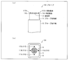
- FIG. 5 is a diagram showing a configuration when the contact electrodes 117b and 117d are arranged on the protrusion structure 115 when viewed from the front of the probe 104.
- FIG. 5B is a diagram showing a configuration when the contact electrodes 117 a, 117 b, 117 c, and 117 d are disposed on the protrusion structure 115 as viewed from above the probe 104.
- the contact electrodes 117b to 117d are arranged at the front end on the side where the protruding structure 115 contacts the skin surface. Further, as shown in FIG. 5B, since the protrusion structures 115 are arranged at four positions on the probe tip 11, one contact electrode 117a (contact electrode 117b, contact electrode 117b, one for each protrusion structure 115). Contact electrodes 117c and 117d) are arranged. Although the contact electrodes 117a and 117c are not shown in FIG. 5A, the contact electrodes 117a and 117c are formed at the tips of the protruding structures 115 in the same manner as the contact electrodes 117b and 117d shown in FIG. Is arranged.
- FIG. 6 is a diagram showing a configuration of an electric circuit connected to the contact electrodes 117a, 117b, 117c, and 117d.
- the electric circuit includes a display unit 109, contact electrodes 117 a, 117 b, 117 c, and 117 d, a constant current source 118, a control unit 119, and a voltage measurement circuit 120.
- the display unit 109, the constant current source 118, the control unit 119, and the voltage measurement circuit 120 may be provided inside the measurement apparatus 1 (FIG. 2), or may be external to the measurement apparatus 1. May be provided.
- the contact electrodes 117a, 117b, 117c, and 117d and the above-described electric circuit are used to detect that the second contact portion such as the protruding structure 115 or the raised structure (see FIG. 3D) has contacted the skin surface.
- a detection means is configured.
- the constant current source 118 supplies current to the contact electrodes 117a, 117b, 117c, and 117d.
- the voltage measuring circuit 120 measures the voltage between two contact electrodes among the contact electrodes 117a, 117b, 117c, and 117d.
- the control unit 119 controls the entire electric circuit, and details will be described later.
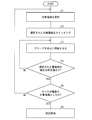
- FIG. 7 is a flowchart for explaining a process of automatically detecting whether or not the protruding structure 115 is in contact with the skin surface using the contact electrodes 117a, 117b, 117c, and 117d.
- Step 1 there are two target electrodes 117a, 117b, 117c, and 117d for determining whether or not the protruding structure 115 is in contact with the skin surface, the control unit 119.
- Step 1 hereinafter, the step is simply referred to as S.
- the contact electrode 117a and the contact electrode 117c are symmetric positions with respect to the center point of the contact portion 14 as shown in FIG.
- control part 119 performs switching of an object electrode (S2).
- the control unit 119 is configured so that the positive electrode of the constant current source 118 is connected to the contact electrode 117a and the negative electrode of the constant current source 118 is connected to the contact electrode 117c.
- the contact electrodes 117a and 117c and the constant current source 118 are connected (switched).
- the control unit 119 includes the contact electrodes 117a and 117c and the voltage measurement so that the positive electrode of the voltage measurement circuit 120 is connected to the contact electrode 117a and the negative electrode of the voltage measurement circuit 120 is connected to the contact electrode 117c.
- the circuit 120 is connected (switched).
- the voltage between the two contact electrodes selected as the target electrode in S1 is measured by the voltage measurement circuit 120, and it is determined whether or not the voltage is equal to or lower than a predetermined value (S4).
- the voltage between the contact electrode 117a and the contact electrode 117c is measured by the voltage measurement circuit 120. If both the contact electrode 117a and the contact electrode 117c are in contact with the skin surface, a voltage drop occurs between the contact electrode 117a and the contact electrode 117c, and a current flows.
- a predetermined voltage value is set in the control unit 119 in advance, and the control unit 119 determines whether the voltage measured between the contact electrode 117a and the contact electrode 117c is equal to or lower than the predetermined voltage value. To do. If it is determined that the measured voltage is not more than the predetermined value, the process proceeds to S5 as shown in FIG. 7, and if it is determined that the voltage is not less than the predetermined value, the process returns to S3. In addition, by notifying the user of whether or not the voltage is equal to or lower than the predetermined value by display or sound on the display unit 109, the user can determine whether or not the two contact electrodes are in contact with the skin surface. Can be known accurately.
- control part 119 judges whether all the contact electrodes arrange
- the contact electrodes 117a and 117c are selected as the target electrodes, but the contact electrodes 117b and 117d are not selected as the target electrodes, the contact electrodes 117b and 117d are selected as the target electrodes.
- the processing flow returns to
- the control unit 119 connects the contact electrodes 117b and 117d so that the positive electrode of the constant current source 118 is connected to the contact electrode 117b and the negative electrode of the constant current source 118 is connected to the contact electrode 117d.
- the constant current source 118 is connected.
- the control unit 119 performs voltage measurement with the contact electrodes 117b and 117d so that the positive electrode of the voltage measurement circuit 120 is connected to the contact electrode 117b and the negative electrode of the voltage measurement circuit 120 is connected to the contact electrode 117d.
- the circuit 120 is connected.
- FIG. 8 is a longitudinal sectional view showing another configuration example of the probe mounted on the measuring apparatus 1 according to the embodiment of the present invention.
- the probe 204 includes a probe handle part (probe main body part) 210, an X direction movable part (movable mechanism) 221, a Y direction movable part (movable mechanism) 222, and a user
- the contact plane 212 includes a contact portion 212a as a first contact portion and a protruding structure 212b as a second contact portion.
- the X-direction movable portion 221 or the Y-direction movable portion 222 provided in the measuring apparatus 1 constitutes a movable mechanism that moves the contact plane 212 so as to properly contact the skin surface. That is, when the contact plane 212 is in contact with the skin surface in an inclined state, the contact plane 212 is adjusted by the movable mechanism so as to properly contact the skin surface.
- the X-direction movable unit 221 moves with the X-direction rotation shaft 223 as the rotation axis.
- the Y-direction movable unit 222 is movable with the Y-direction rotation shaft 224 as the rotation axis.
- the contact plane 212 moves so as to be interlocked with the X-direction movable portion 221.
- the X direction movable part 221 and the Y direction movable part 222 have a function of appropriately bringing the contact plane 212 into contact with the skin surface and adjusting the irradiation angle of the excitation light.
- the Y direction movable part 222 is connected to the probe handle part 210 by the Y direction rotating shaft 224. As shown in FIG. 8, the Y-direction rotating shaft 224 is attached at two locations so as to be symmetric with respect to the Y-direction moving portion 222 in order to move the Y-direction movable portion 222 with the Y-direction rotating shaft 224 as the rotation axis. It has been. However, the Y-direction movable unit 222 is not necessarily provided, and the irradiation angle of the excitation light may be adjusted only by the X-direction movable unit 221. When the Y-direction movable portion 222 is not provided, the X-direction movable portion 221 is disposed at the same position as the Y-direction movable portion 222 as described above.
- the Y-direction movable portion 222 is movable on the side of the probe handle portion 210 that contacts the skin surface.
- a depression having a size within a range to be formed is formed.
- the X direction movable portion 221 is connected to the Y direction movable portion 222 by the X direction rotating shaft 223.
- the X-direction rotation shaft 223 is also attached at two locations so as to be symmetric with respect to the X-direction movable portion 221 in order to move the X-direction movable portion 221 with the X-direction rotation shaft 223 as the rotation axis.
- FIG. 8 only one X-direction rotation shaft 223 is illustrated, but it should be noted that the other one is attached to the opposite side with the X-direction movable portion 221 interposed therebetween.
- a range in which the X-direction movable portion 221 can move is provided inside the Y-direction movable portion 222. Considered depressions are formed.
- the axis line when connecting two X direction rotating shafts 223 with a straight line and the axis line when connecting two Y direction rotating shafts 224 with a straight line may not be parallel or overlap. Because, if the X direction rotating shaft 223 and the Y direction rotating shaft 224 are attached so that the two axes are parallel or overlap, the X direction movable portion 221 and the Y direction movable portion 222 are movable in the same direction. End up. As a result, the direction in which the irradiation angle of the excitation light can be adjusted is only one direction.
- the irradiation angle of the excitation light is only in one direction, it can be realized only by the X direction movable portion 221 without attaching the Y direction movable portion 222. That is, if the X-direction rotation shaft 223 and the Y-direction rotation shaft 224 are attached so that two axes are parallel or overlap, and two movable portions of the X-direction movable portion 221 and the Y-direction movable portion 222 are provided, the number of parts increases. This is because there is a possibility that the meaning of providing two movable parts is lost.
- the two axes of the X-direction rotating shaft 223 and the Y-direction rotating shaft 224 are in a twisted position, and are preferably arranged in directions extending in directions different from each other by 90 °. That is, by attaching the X-direction rotating shaft 223 and the Y-direction rotating shaft 224 so that the axes are in the arrangement, the movable range of the contact plane 212 described later attached to the X-direction movable portion 221 is maximized, This is because the irradiation angle of the excitation light can be adjusted flexibly. This is because angle adjustment in two directions can be performed by the X-direction rotation shaft 223, and angle adjustment in two directions can be further performed by the Y-direction rotation shaft 224, so that angle adjustment in a total of four directions is realized. .
- the contact plane 212 is attached to the X direction movable portion 221 and fixes the bundle fiber 3.
- the contact plane 212 operates according to the movement of the X-direction movable portion 221 or the Y-direction movable portion 222 as it moves.
- the bundle fiber 3 is passed through the probe handle 210 from the side opposite to the contact plane 212, and the tip of the bundle fiber 3 is fixed to the contact plane 212 so as to be sandwiched by the contact plane 212. Yes.
- two types of fibers excitation optical fiber 7 and light receiving optical fiber 8) are inserted as described above.
- FIG. 9A is a view of the X direction movable portion 221 as viewed from above
- FIG. 9B is a view of the X direction movable portion 221 as viewed from the front
- FIG. 9C is a view of the X direction. It is the figure which looked at the movable part 221 from the lower part
- (d) of FIG. 9 is the figure which looked at the X direction movable part 221 from the side.
- the X-direction movable portion 221 includes an X-direction movable main body portion 225, an irradiation / light receiving hole 226, a bundle fiber passage hole 213a, and two X-direction rotary bearings 227. Have.
- the irradiation / light receiving hole 226 shown in FIG. 9A is disposed at the center of the X-direction movable main body 225 so that the bundle fiber 3 can be inserted through the bundle fiber passage hole 213a. .
- the size or shape of the irradiation / light receiving hole 226 can be freely designed according to the bundle fiber 3.
- the irradiation / light receiving hole 226 extends to the lower portion of the X-direction movable main body 225 and is connected to the bundle fiber passage hole 213a.
- the bundle fiber passage hole 213a is larger than the irradiation / light receiving hole 226. This is because there is a need for an area where the bundle fiber 3 can move in the X-direction movable portion 221 when the X-direction movable portion 221 moves around the X-direction rotation shaft 223 as the rotation axis. is there.
- the X-direction rotary bearing 227 shown in FIGS. 9A, 9B, and 9D is for inserting the X-direction rotary shaft 223.
- the place where the X direction rotation bearing 227 is arranged may be determined according to the arrangement of the X direction rotation shaft 223.
- the two X-direction rotary bearings 227 are preferably arranged at positions that are symmetric with respect to the irradiation / light receiving hole 226.
- FIG. 10A is a view of the Y-direction movable portion 222 as viewed from above
- FIG. 10B is a view of the Y-direction movable portion 222 as viewed from the front
- FIG. 10D is a view of the Y-direction movable portion 222 as viewed from the side.
- the Y-direction movable portion 222 includes a Y-direction movable main body 228, two X-direction rotating shafts 223, and bundle fiber passage holes 213b. And two Y-direction rotary bearings 229.
- the Y-direction movable main body 228 is connected to the X-direction movable portion 221 via the X-direction rotation shaft 223. It has a shape with a dent.
- the size of the recess may be any size as long as the X-direction movable unit 221 can be moved using the X-direction rotation shaft 223 as a rotation axis.
- the two X-direction rotating shafts 223 are arranged in the Y-direction movable main body 228 so as to be symmetric with respect to the bundle fiber passage hole 213b.
- the X-direction rotation shaft 223 serves as a rotation axis for moving the X-direction movable unit 221.
- two Y-direction rotary bearings 229 are arranged on a different surface from the surface of the Y-direction movable main body 228 on which the X-direction rotary shaft 223 is arranged. Similarly to the X-direction rotating shaft 223, the Y-direction rotating bearing 229 is also arranged to be symmetric with respect to the bundle fiber passage hole 213b. Further, a Y-direction rotating shaft 224 is inserted into the Y-direction rotating bearing 229.
- the bundle fiber passage hole 213b allows the bundle fiber 3 to pass in the same manner as the bundle fiber passage hole 213a.
- the bundle fiber passage hole 213b has a long rectangular shape in the direction of the axis formed by connecting the two X-direction rotation shafts 223 as shown in FIG. This is because, when the Y-direction movable unit 222 rotates about the Y-direction rotation shaft 224 as the rotation axis, the bundle fiber 3 is formed by connecting the two X-direction rotation shafts 223 with the rotation of the Y-direction rotation shaft 224. Move in the direction of. This is because an area in which the bundle fiber 3 moves is necessary.
- FIG. 11 shows a longitudinal sectional view of the probe handle 210.
- the probe handle part 210 is configured by a Y-direction rotating shaft 224, a bundle fiber passage hole 213c, and a probe handle body part 230.
- the probe handle body 230 is shaped and sized to be easily held by a human hand. Further, the tip of the probe handle main body 230 on the side close to the skin surface has a shape with a depression. As described above, this is because the Y-direction movable portion 222 disposed above the probe handle portion 210 can be moved using the Y-direction rotation shaft 224 as a rotation axis.
- the contact plane 312 adjusts the pressure that contacts the skin surface. Can do. By appropriately adjusting the pressure, the irradiation angle of the excitation light can be stabilized. Therefore, measurement with high reproducibility can be performed. This point will be described below with reference to FIGS. 12A and 12B.
- FIG. 12 (a) and 12 (b) are diagrams showing the Z-direction movable part 331 provided on the probe 304.
- FIG. 12A is a longitudinal sectional view of the probe 304
- FIG. 12B is a side view of the Y-direction movable portion 322 and the X-direction movable portion 321.
- the contact plane 312 includes a contact portion 312a as a first contact portion and a protruding structure 312b as a second contact portion. Further, an X-direction rotating shaft 323 is provided to connect the X-direction movable portion 321 and the Y-direction movable portion 322.
- the Z-direction movable portion 331 is disposed between the probe handle portion 310 and the Y-direction movable portion 322.
- the Z direction movable part 331 should just be arrange
- the Z-direction movable part 331 may be composed of anything as long as it has elasticity.
- a spring or rubber can be considered.
- the Y-direction movable portion 322 rotates in the Y-direction as shown in FIG.
- a bearing 329 is provided inside the Y-direction rotary bearing 329. Inside the Y-direction rotary bearing 329, a long hole is formed in the direction in which the Z-direction movable portion 331 extends and contracts so that the Y-direction rotary shaft 324 can move up and down in the Z direction.
- FIG. 12B an X direction rotating shaft 323 and a Y direction rotating shaft 303 are shown.
- the X direction rotation shaft 323 serves as the rotation axis of the X direction movable portion 321
- the Y direction rotation shaft 324 serves as the rotation axis of the Y direction movable portion 322. Since the X-direction rotation shaft 323 corresponds to the X-direction rotation shaft 223 and the Y-direction rotation shaft 324 corresponds to the Y-direction rotation shaft 224, description thereof is omitted here.
- the measuring apparatus measures AGEs in the skin by irradiating the skin with excitation light. Then, the first contact unit that holds the irradiation unit that irradiates the living body with the excitation light and that contacts the living body, and the second contact surface that contacts the living body in substantially the same plane as the contact surface that contacts the living body.
- the contact portion the user can know whether or not the probe has properly contacted the skin surface. Therefore, it is possible to measure the AGEs in the skin with high reproducibility by correcting the contact state of the probe by the user himself / herself.
- the measurement apparatus includes an irradiation unit that irradiates a living body with excitation light guided from an excitation light source, and a light reception unit that receives fluorescence generated by irradiation of the excitation light.
- a first contact unit that holds the irradiation unit and contacts the living body; and a second contact unit that contacts the living body in a substantially same plane as a contact surface where the first contact unit contacts the living body. It is what has.
- a 2nd contact part contacts a biological body by having a 2nd contact part which the said 1st contact part contacts the said biological body in the substantially same plane as the contact surface which contacts a biological body. Then, the living body (user) can feel that the second contact portion has contacted the skin of the living body. The living body can confirm that the contact state of the first contact portion is not tilted by the contact area or the like by feeling that the second contact portion is in contact with the skin. Thereby, the living body that has felt that the measuring device is tilted can be corrected to the state in which the first contact portion is not tilted by the living body itself. Therefore, since the first contact portion can be brought into contact with the living body in an appropriate contact state, it is possible to irradiate excitation light at an appropriate angle and receive fluorescence. Therefore, the reproducibility of measurement can be improved.
- the second contact portion includes two or more protrusions that protrude in a direction in which the first contact portion contacts the living body. Also good.
- the living body By configuring the second contact portion from two or more protrusions as in the above configuration, the living body (user) does not tilt the contact state of the first contact portion based on the number of protrusions in contact with the second contact portion. You can know if. In addition, when the direction in which the protrusions are raised is the direction in which the first contact portion is in contact with the living body, it can be appropriately felt that the first contact portion has contacted the living body.
- the second contact part is two protrusions and the living body feels that only one second contact part is in contact with the living body, the other second contact part is not in contact with the living body. It will be.
- the fact that both protrusions are not in contact with the living body means that the first contact portion is tilted and is in contact with the living body, and the living body that knows that the first contact portion is tilted is two It can be corrected by itself so that the protrusion contacts the living body.
- the second contact portion may have a shape surrounding the first contact portion.
- the second contact portion by making the second contact portion into a shape surrounding the first contact portion, variations in which the second contact portion can be designed can be expanded.
- the shape of the second contact portion can be a circle or a polygon.
- one aspect of the measurement apparatus of the present invention may have a contact detection means for detecting that the second contact portion has contacted the living body in the measurement apparatus having the above configuration.
- the second contact portion is in contact with the living body without depending on the touch of the living body (user). Can be detected.
- the contact detecting unit measures a voltage between two points in the second contact portion, so that the second contact portion is applied to a living body. You may detect having contacted.
- the contact detection means measures the voltage between two points in the second contact portion, and knows that the first contact portion has properly contacted the living body by knowing that the voltage has decreased. Can do.
- the excitation light may have a wavelength range suitable for measuring a late saccharification reaction product.
- the AGEs in the living body can be appropriately measured by setting the wavelength range of the excitation light to a wavelength range suitable for measuring the late saccharification reaction product.
- one aspect of the measurement apparatus of the present invention may include a movable mechanism that moves the first contact portion so that an irradiation angle of the excitation light to the living body is adjusted in the measurement apparatus having the above configuration.
- the first contact portion can be moved by providing a movable mechanism. Therefore, the irradiation angle of the excitation light irradiated to the living body from the irradiation unit held by the first contact unit can be adjusted, and the irradiation unit can irradiate the living body with the excitation light at an appropriate irradiation angle. . Therefore, the reproducibility of measurement can be improved.
- the movable mechanism may include a moving mechanism that moves the first contact portion and the living body in a direction to separate or approach the living body. Good.
- the movement mechanism can adjust the pressure applied to the living body by the first contact section by moving the first contact section in the direction of separating or approaching the living body.
- a 1st contact part can be made to contact a biological body with a suitable pressure, the irradiation angle of excitation light can be stabilized, and the reproducibility of a measurement can further be improved.
- the present invention can be used for a measuring device for evaluating the health condition and aging of the skin by monitoring AGEs in the skin.
Landscapes
- Health & Medical Sciences (AREA)
- Life Sciences & Earth Sciences (AREA)
- Physics & Mathematics (AREA)
- General Health & Medical Sciences (AREA)
- Pathology (AREA)
- Biomedical Technology (AREA)
- Veterinary Medicine (AREA)
- Heart & Thoracic Surgery (AREA)
- Medical Informatics (AREA)
- Molecular Biology (AREA)
- Surgery (AREA)
- Animal Behavior & Ethology (AREA)
- Biophysics (AREA)
- Public Health (AREA)
- Engineering & Computer Science (AREA)
- Nuclear Medicine, Radiotherapy & Molecular Imaging (AREA)
- Chemical & Material Sciences (AREA)
- Analytical Chemistry (AREA)
- Biochemistry (AREA)
- General Physics & Mathematics (AREA)
- Immunology (AREA)
- Investigating, Analyzing Materials By Fluorescence Or Luminescence (AREA)
- Investigating Or Analysing Biological Materials (AREA)
- Measurement Of The Respiration, Hearing Ability, Form, And Blood Characteristics Of Living Organisms (AREA)
- Measuring And Recording Apparatus For Diagnosis (AREA)
Abstract
励起光を傾けて照射することにより、皮膚状態の測定の再現性が悪くなる。 励起光源(5)から導光される励起光を生体に照射する照射部(7)と、励起光の照射によって生じる蛍光を受光する受光部(8)とを備える測定装置(1)であって、照射部(7)を保持するとともに生体に接触する第1接触部(14)と、第1接触部(14)が生体と接触する接触面とほぼ同一平面にて、生体と接触する第2接触部(15、16、115)とを有している。
Description
本発明は、肌の状態を測定する測定装置に関する。
従来、抗糖化(抗加齢)化粧品として、肌に蓄積したAGEs(Advanced Glycation Endproducts;後期糖化反応生成物)の低減を目的としたものが商品化されている。このAGEsは、タンパク質と、糖質や脂質との非酵素的糖付加反応(メイラード反応)により形成される最終生成物であり、黄褐色を呈し、その一部は蛍光を発する物質である。また、AGEsは、近くに存在する構造蛋白質と結合して架橋を形成する性質を有している。特にAGEsと真皮を構成しているコラーゲンとの架橋は、皮膚の弾力性を低下させ、また、しわやくすみの原因としても問題となっている。そのため、AGEsをモニタリングすることで、肌の健康状態、老化を評価することができる。
皮膚中に蓄積したAGEs量を正確に評価可能な装置は、AGEsを減少させる市販のクリーム等によるケアの必要性を、ユーザに認識させる手段として有用である。
皮膚状態を評価可能な装置として、特許文献1のような装置が知られている。特許文献1では、少なくとも一つ以上の光源から照射された励起光を皮膚に照射し、皮膚から反射された蛍光をパラメーターとすることによって、皮膚状態を測定する装置が開示されている。
励起光は、皮膚表面に対して垂直に照射されることが好ましい。しかしながら、前記特許文献1に開示されているような皮膚状態を評価する装置であれば、励起光を皮膚表面に照射するときに、皮膚表面に対して傾けてプローブを接触させてしまうと、傾けた角度のまま励起光を照射してしまうという問題が生じる。
なぜなら、特許文献1に記載の装置では、ユーザが、プローブを皮膚表面に接触させるとき、プローブが皮膚表面に接触する面が適切になるかどうかは、ユーザの接触させ方次第であるからである。もし、ユーザがプローブを傾けた状態で皮膚に接触させたとしても、それを修正する手段はプローブには備えられていない。そのため、皮膚表面に対して、傾けた角度で励起光を照射し、皮膚状態を測定することになるので、測定の再現性が悪くなる。
本発明は、前記問題点に鑑みてなされたものであり、ユーザが、プローブを傾けて皮膚表面に接触させたときであっても、プローブが傾けて皮膚表面に接触していることを、ユーザに伝達することにより、ユーザ自身でプローブの傾きを修正し、測定の再現性を向上させることができる測定装置を提供することにある。
本発明の一態様に係る測定装置は、励起光源から導光される励起光を生体に照射する照射部と、前記励起光の照射によって生じる蛍光を受光する受光部とを備える測定装置であって、前記照射部を保持するとともに前記生体に接触する第1接触部と、前記第1接触部が前記生体と接触する接触面とほぼ同一平面にて、前記生体と接触する第2接触部とを有しているものである。
本発明に係る測定装置は、前記のように構成されることにより、適切に励起光を照射することができ、測定の再現性を高めることができる。
本発明の実施形態について、図1~図12に基づいて説明すると以下の通りである。
なお、説明の便宜上、前記実施の形態にて説明した図面と同じ機能を有する部材については、同じ符号を付記し、その説明を省略する。また、本発明は後述の各実施形態に限定されるものではなく、請求項に示した範囲で種々の変更が可能であり、異なる実施形態にそれぞれ開示された技術的手段を適宜組み合わせて得られる実施形態についても本発明の技術的範囲に含まれる。
本発明に係る測定装置は、プローブの先端を人間の皮膚表面に接触させ、皮膚表面に励起光を照射し、照射された励起光によって発生した蛍光を受光することにより、皮膚に生じる後期糖化反応性生物(以下AGEs)を測定するための装置である。励起光は、皮膚表面に対して、垂直に照射されることが好ましい。なぜなら、本発明が測定の対象としているAGEsは、皮膚の表面だけでなく、皮膚の内部にも蓄積しているものであり、励起光の損失をできるだけ軽減し皮膚の深部にまで励起光を照射する必要があるからである。本発明は、励起光を皮膚表面に対して、簡易に垂直に照射することができるような装置を実現することを目指したものである。
すなわち、本発明は、励起光を生体に照射する照射部を保持するとともに生体に接触する第1接触部と、当該第1接触部が生体と接触する接触面とほぼ同一平面にて、生体と接触する第2接触部とを設けることで、ユーザにプローブを垂直に皮膚表面に接触させることができていないことをユーザに伝達することにより、ユーザ自身でプローブを垂直に皮膚表面に接触させるように修正できる測定装置である。
〔1.測定装置概要について〕
図2は、本発明の一実施形態に係る測定装置1の構成を示す図である。図2に示すように、測定装置1は、測定装置本体部2と、バンドルファイバー3と、プローブ4とから構成されている。
図2は、本発明の一実施形態に係る測定装置1の構成を示す図である。図2に示すように、測定装置1は、測定装置本体部2と、バンドルファイバー3と、プローブ4とから構成されている。
そして、測定装置本体部2は、励起光源5および分光器6が備えられている。励起光源5には、バンドルファイバー3で束ねられている励起側光ファイバー(照射部)7が接続され、分光器6には、受光側光ファイバー(受光部)8が接続されている。バンドルファイバー3の測定装置本体部2の反対側の先端は、プローブ4に接続されている。
励起光源5で生成される励起光は、AGEsを測定するために適している波長範囲であることが望まれる。つまり、励起光源5から生成される励起光は、UVAの領域である315~400nmの波長を有するものであることが好ましい。当該領域の波長を有する光を励起光とすることによってAGEsを適切に測定することができる。
さらに、分光器6は、受光側光ファイバー8で導光されてきた蛍光を検出し、分析するものである。その分析された結果は、表示部9に送信される。表示部9は、映像を表示できるものであれば何でもよく、例えば、専用の液晶表示装置、CRT、パソコンやテレビ等が挙げられる。
〔2.プローブにおけるX方向可動装置の構成について〕
図1の(a)は、測定装置1に搭載されるプローブ4の構成を正面からみた図であり、図1の(b)は、プローブ4を上方からみた図である。
図1の(a)は、測定装置1に搭載されるプローブ4の構成を正面からみた図であり、図1の(b)は、プローブ4を上方からみた図である。
図1の(a)に示すように、本実施形態に係るプローブ4は、プローブ取手部10(プローブ本体部)と、プローブ先端部11とを備えている。
そして、プローブ先端部11の皮膚表面に接触させる側には、接触平面12が配置されている。また、プローブ取手部10の中心には、バンドルファイバー3を挿入するバンドルファイバー通過穴13が形成されている。バンドルファイバー通過穴13は、プローブ4において、接触平面12から、その反対側まで貫通するように形成されている。
また、接触平面12は、接触部(第1接触部)14と、突起構造(第2接触部)15とから構成されている。接触部14は皮膚表面に接触させるものであり、プローブ先端部11の中心に配置されている。一方で、突起構造15は、接触部14が皮膚表面と接触する接触面とほぼ同一平面にて皮膚表面に接触するよう、プローブ先端部11から隆起するものである。
さらに、突起構造15は、図1の(b)に示すように、接触部14の周囲に4箇所配置される。4箇所の突起構造15は、接触部14の中心から、任意に定めた長さの半径の円周上に等間隔で配置すればよい。なお、接触部14の皮膚表面に接触する側の面と、突起構造15の皮膚表面に接触側する先端との間には、1mm程度の高低差が存在してもよい。
前記のように突起構造15を4箇所配置することによって、4箇所すべてが皮膚表面に接触したときに、接触部14が皮膚表面に対して適切に接触したことになる。突起構造15がすべて皮膚表面に接触したかどうかは、ユーザ自身が皮膚の感覚で判断する。もし、4箇所の突起構造15のうち2箇所しか接触していないことをユーザ自身が感じれば、4箇所すべて接触していると感じられるように、ユーザ自身がプローブ4を動かすことで修正する必要がある。
前記のように、突起構造15のすべてがユーザの皮膚表面に接触していることを確実に感じるためには、接触部14の中心から1cm程度の半径の円周上に突起構造15が配置されていることが好ましい。なぜなら、突起構造15がすべて皮膚に接触したかどうかは、個人差はあるが、接触部14の中心から1cm程度離れたところに配置すると、突起構造15が接触したことを大半のユーザが認識できると想定されるためである。
〔3.突起構造の配置および隆起構造の形状について〕
図3の(a)、図3の(b)、および図3の(c)は、突起構造15の他の構成例を示す図である。また、図3の(d)は、突起構造15の代替構成である隆起構造16(詳細は後述する)をプローブ先端部11に設けたときの構成を示す図である。
図3の(a)、図3の(b)、および図3の(c)は、突起構造15の他の構成例を示す図である。また、図3の(d)は、突起構造15の代替構成である隆起構造16(詳細は後述する)をプローブ先端部11に設けたときの構成を示す図である。
図3の(a)に示すように、プローブ先端部11には、2箇所の突起構造15を配置してもよい。あるいは、図3の(b)に示すように、プローブ先端部11には、3箇所の突起構造15を配置してもよいし、図3の(c)に示すように、6箇所の突起構造15を配置してもよい。さらに、図3の(a)~図3の(c)に示すように、突起構造15は、接触部14を中心とする円周上に配置され、各々の突起構造15が等間隔に配置されているのであれば、突起構造15の数は適宜変更してもよい。各々の突起構造15が等間隔で配置される理由は、各々の突起構造15がユーザの皮膚表面に与える圧力を均一にしなければならないからである。なぜなら、各々の突起構造15によって皮膚表面に対して与えられる圧力が均一でなければ、突起構造15が皮膚表面に接触したとしても、突起構造15を平面であるとユーザが認識できなくなるためである。そのため、プローブ4の皮膚表面に対する傾きをユーザが正確に判断できなくなる虞がある。また、接触部14の中心から、半径1cm程度の円周上に、突起構造15が配置されることが好ましい。
さらに、図3の(d)に示すように、接触部14の周囲に円形状の隆起構造(第2接触部)16を設けてもよい。隆起構造16は、接触部14が皮膚表面と接触する接触面とほぼ同一平面にて皮膚表面に接触するよう、プローブ先端部11から隆起するものである。
また、隆起構造16は、円形状である必要はなく、例えば、接触部14を取り囲む多角形であってもよい。ただし、突起構造15の配置位置と同様に、接触部14の中心から1cm程度離れた位置に隆起構造16が配置されることが好ましい。
以上より、突起構造15の配置箇所数または隆起構造16の形状は、様々な形態をとることができ、設計のバリエーションを増やすことができる。
〔4.バンドルファイバーの構成について〕
図4は、プローブ4のバンドルファイバー通過穴13に挿入されるバンドルファイバー3の断面図を示した図である。バンドルファイバー3は、2種類の光ファイバーを束ねる役割をしており、励起側光ファイバー7と、受光側光ファイバー8を束ねている。バンドルファイバー3の中心には、励起光を皮膚表面に照射することにより、発生した蛍光を受光する受光側光ファイバー8が配置されている。
図4は、プローブ4のバンドルファイバー通過穴13に挿入されるバンドルファイバー3の断面図を示した図である。バンドルファイバー3は、2種類の光ファイバーを束ねる役割をしており、励起側光ファイバー7と、受光側光ファイバー8を束ねている。バンドルファイバー3の中心には、励起光を皮膚表面に照射することにより、発生した蛍光を受光する受光側光ファイバー8が配置されている。
また、受光側光ファイバー8の外周には、励起光を照射する励起側光ファイバー7が複数設けられている。ただし、励起側光ファイバー7および受光側光ファイバー8の配置関係は、図4に示された配置に限定されるものではなく、適宜設定すればよい。
しかしながら、受光側光ファイバー8は、バンドルファイバー3の外部からの光をなるべく受光しないよう、バンドルファイバー3の中心位置近傍に設けられることが好ましい。また、励起側光ファイバー7および受光側光ファイバー8についての断面積(太さ)も、適宜選択すればよい。
また、励起側光ファイバー7は、励起光源5で発生させた励起光を、接触部14が配置されている側まで導光し、皮膚の表面に照射するものである。また、皮膚表面に励起光を照射することにより発生した蛍光は、受光側光ファイバー8によって受光され、分光器6に導光される。
〔5.接触電極を配置する構成について〕
さらに、プローブ先端部に配置されている突起構造に接触電極を設けることにより、突起構造が皮膚表面に接触したかどうかを自動的に検知することができる。この点について以下に説明する。
さらに、プローブ先端部に配置されている突起構造に接触電極を設けることにより、突起構造が皮膚表面に接触したかどうかを自動的に検知することができる。この点について以下に説明する。
図5の(a)は、突起構造115に接触電極117b・117dが配置された状態を、プローブ104の正面からみたときの構成を示す図である。また、図5の(b)は、突起構造115に接触電極117a・117b・117c・117dが配置された状態を、プローブ104の上方からみたときの構成を示す図である。
図5の(a)に示すように、突起構造115が皮膚表面に接触する側の先端に、接触電極117bないし接触電極117dは配置されている。また、図5の(b)に示すように、突起構造115はプローブ先端部11に4箇所配置されているため、それぞれの突起構造115に対して1つずつ、接触電極117a(接触電極117b,接触電極117c,接触電極117d)が配置されている。なお、図5の(a)には接触電極117a・117cは図示されていないが、図5の(a)に示す接触電極117b・117dと同様に、突起構造115の先端に接触電極117a・117cは配置されている。
また、図6は、接触電極117a・117b・117c・117dと接続される電気回路の構成を示す図である。図6で示すように、当該電気回路は、表示部109と、接触電極117a・117b・117c・117dと、定電流源118と、制御部119と、電圧測定回路120とを備えている。なお、表示部109と、定電流源118と、制御部119と、電圧測定回路120とは、測定装置1(図2)の内部に設けられる構成であってもよいし、測定装置1の外部に設けても構わない。そして、接触電極117a・117b・117c・117dと、上記電気回路により、突起構造115や隆起構造(図3の(d)参照)などの第2接触部が皮膚表面に接触したことを検出する接触検出手段が構成される。
定電流源118は、接触電極117a・117b・117c・117dに対して電流を供給するものである。また、電圧測定回路120は、接触電極117a・117b・117c・117dのうち、2箇所の接触電極の間の電圧を測るものである。制御部119は、電気回路全体を制御するものであり、詳細は後述する。
図7は、接触電極117a・117b・117c・117dを用いて、突起構造115が皮膚表面に接触したかどうかが自動的に検知されるプロセスを説明するフローチャートである。
まず、図7に示すように、突起構造115が皮膚表面に接触しているかどうかを判定するための対象電極が、4つの接触電極117a・117b・117c・117dの中から2つ、制御部119により選択される(ステップ1、以下、単にステップはSと記載する)。なお、S1において選択される対象電極は、接触部14の中心点に関して対称となる2箇所の接触電極を選択することが望ましい。たとえば、接触電極117aと接触電極117cとは、図5の(b)に示すように、接触部14の中心点に関して対称の位置にあるので、対象電極の理想的な選択肢となりうる。
そして、図7に示すように、選択された2箇所の接触電極に対して電流を流すために、制御部119が対象電極のスイッチングを行う(S2)。
たとえば、前述のとおり、接触電極117aと接触電極117cの2つの電極が対象電極として選択されたとする。この場合、図6に示す回路構成において、定電流源118の+極が接触電極117aに接続されるとともに、定電流源118の-極が接触電極117cに接続されるよう、制御部119は、接触電極117a・117cと、定電流源118とを接続(スイッチング)する。同時に、電圧測定回路120の+極が接触電極117aに接続されるとともに、電圧測定回路120の-極が接触電極117cに接続されるよう、制御部119は、接触電極117a・117cと、電圧測定回路120とを接続(スイッチング)する。
このようにしてS2における対象電極のスイッチングが完了した後、図7に示すように、ユーザが、プローブ104を皮膚表面に接触させる(S3)。
その後、S1において対象電極として選択された2箇所の接触電極間の電圧が、電圧測定回路120により測定され、その電圧が所定値以下であるか否かが判断される(S4)。
たとえば、前述のとおり、対象電極とした接触電極117a・117cが選択されているとすると、接触電極117aと接触電極117cとの間の電圧が、電圧測定回路120によって測定される。そして、接触電極117aおよび接触電極117cのいずれも皮膚表面に対して接触していれば、接触電極117aと接触電極117cとの間に電圧降下が生じ電流が流れる。
したがって、制御部119に予め所定の電圧値を設定しておくとともに、接触電極117aと接触電極117cとの間に測定された電圧が、所定の電圧値以下であるかどうかを制御部119により判断する。もし、測定された電圧が所定値以下であると判断されれば、図7に示すように、S5に進み、電圧が所定値以下でないと判断されれば、S3に戻る。なお、電圧が所定値以下であるのか否かの判断を、表示部109における表示や音声によりユーザに報知することで、ユーザは、2つの接触電極がいずれも皮膚表面に接触しているか否かを的確に知ることができる。
そして、S5においては、プローブ先端部11に配置されている接触電極がすべて対象電極とされたかどうかを、制御部119は判断する。もし、プローブ先端部11に配置されているすべての接触電極が対象電極とされていれば、励起光が皮膚表面に照射されることにより、皮膚状態の測定が開始される(S6)。また、プローブ先端部11に配置されている接触電極の中で、対象電極とされていない接触電極があれば、S1に戻る。
たとえば、前述のとおり、接触電極117a・117cが対象電極として選択されているが、接触電極117b・117dが対象電極として選択されていない場合は、接触電極117b・117dを対象電極とすべく、S1に処理フローが戻る。
その後、S2において、定電流源118の+極が接触電極117bに接続されるとともに、定電流源118の-極が接触電極117dに接続されるよう、制御部119は、接触電極117b・117dと、定電流源118とを接続する。同時に、電圧測定回路120の+極が接触電極117bに接続されるとともに、電圧測定回路120の-極が接触電極117dに接続されるよう、制御部119は、接触電極117b・117dと、電圧測定回路120とを接続する。
そして、S3およびS4を踏むことにより、接触電極117bと接触電極117dとの間の電圧が、所定の電圧値以下であるかどうかが制御部119により判断される。その結果、接触電極117bと接触電極117dとの間の電圧が所定値以下であると判断されるとともに、全ての接触電極が対象電極とされたら、表示部109に、すべての突起構造115が皮膚表面に接触したことを表示することでユーザに知らせる。また、同時に皮膚状態の測定が開始される。
〔6.可動機構を備えたプローブの構成について〕
図8は、本発明の一実施形態に係る測定装置1に搭載されるプローブの他の構成例を示す縦断面図である。
図8は、本発明の一実施形態に係る測定装置1に搭載されるプローブの他の構成例を示す縦断面図である。
図8に示すように、本構成例に係るプローブ204は、プローブ取手部(プローブ本体部)210と、X方向可動部(可動機構)221と、Y方向可動部(可動機構)222と、ユーザに接触する接触平面(第1接触部、第2接触部)212と、X方向回転軸223と、Y方向回転軸224と、バンドルファイバー3とを有している。なお、接触平面212は、第1接触部としての接触部212aと、第2接触部としての突起構造212bとにより構成される。
そして、詳細は後述するが、測定装置1に設けられたX方向可動部221またはY方向可動部222により、適切に皮膚表面に接触するよう接触平面212を可動させる可動機構が構成される。すなわち、接触平面212が皮膚表面に対して傾いた状態で接触したとき、可動機構によって接触平面212が適切に皮膚表面に接触するように調節されるのである。
より具体的に説明すれば、X方向可動部221は、X方向回転軸223を回転軸として可動する。一方、Y方向可動部222は、Y方向回転軸224を回転軸として可動する。このようにX方向可動部221およびY方向可動部222が可動することによって、接触平面212はX方向可動部221に連動するように可動する。これにより、X方向可動部221およびY方向可動部222は、接触平面212を適切に皮膚表面に接触させ、励起光の照射角度を調節する機能を有しているものである。
また、Y方向可動部222は、プローブ取手部210と、Y方向回転軸224によって接続されている。Y方向回転軸224は、図8に示すように、Y方向可動部222を、Y方向回転軸224を回転軸として可動させるために、Y方向可動部222に関して対称となるように2箇所に取り付けられている。ただし、Y方向可動部222は、必ずしも備える必要はなく、X方向可動部221のみで励起光の照射角度を調節してもよい。Y方向可動部222が備えられていないときには、X方向可動部221が前記で説明したようなY方向可動部222と同じ位置に配置されることになる。
さらに、Y方向回転軸224を回転軸としてプローブ取手部210の内側でY方向可動部222を可動させるために、プローブ取手部210の皮膚表面に接触させる側には、Y方向可動部222が可動する範囲の大きさの窪みが形成されている。
また、X方向可動部221は、Y方向可動部222とX方向回転軸223によって接続されている。X方向回転軸223についても、X方向回転軸223を回転軸としてX方向可動部221を可動させるために、X方向可動部221に関して対称となるように2箇所に取り付けられている。ただし、図8においては、X方向回転軸223は1箇所のみしか記載されていないが、他の1箇所は、X方向可動部221を挟んで反対側に取り付けられていることに留意されたい。
さらに、X方向回転軸223を回転軸としてY方向可動部222の内側でX方向可動部221を可動させるために、Y方向可動部222の内側には、X方向可動部221の可動する範囲を考慮した窪みが形成されている。
なお、2箇所のX方向回転軸223を直線で結んだときの軸線と、2箇所のY方向回転軸224を直線で結んだときの軸線は、平行または重ならないように配置することが好ましい。なぜなら、もし、2本の軸線が平行または重なるになるように、X方向回転軸223およびY方向回転軸224を取り付けると、X方向可動部221およびY方向可動部222は同じ方向に可動してしまう。これに伴い、励起光の照射角度の調節をすることができる方向が1方向のみになってしまう。
しかしながら、励起光の照射角度を1方向のみとするのであれば、Y方向可動部222を取り付けずに、X方向可動部221のみで実現することができる。つまり、2本の軸線が平行または重なるようにX方向回転軸223およびY方向回転軸224を取り付け、X方向可動部221およびY方向可動部222の2つの可動部を設けると、部品数が増えるが1方向のみの可動しかできないので、わざわざ2つの可動部を設ける意味が無くなる虞があるからである。
すなわち、X方向回転軸223およびY方向回転軸224による2本の軸線は、ねじれの位置にある関係であり、互いに90°異なる方向に伸びる方向に配置されていることが好ましい。それは、軸線を当該配置になるように、X方向回転軸223およびY方向回転軸224を取り付けることによって、X方向可動部221に取り付けられている後述する接触平面212の可動範囲が最大になり、フレキシブルに励起光の照射角度を調節することができるからである。なぜなら、X方向回転軸223により2方向に角度調節を行うことができ、しかもY方向回転軸224によりさらに2方向の角度調節ができるので、合計4方向の角度調節が実現されているからである。
また、接触平面212は、X方向可動部221に取り付けられ、バンドルファイバー3を固定している。そして、接触平面212は、X方向可動部221またはY方向可動部222が可動することにより、それらの動きにともなった動作をする。
さらに、プローブ取手部210の内部には、接触平面212とは反対側からバンドルファイバー3が通されており、バンドルファイバー3の先端は、接触平面212によって挟み込まれるように接触平面212に固定されている。そして、バンドルファイバー3の内部には、前述のとおり、2種類のファイバー(励起側光ファイバー7、受光側光ファイバー8)が挿入されている。
以下、各構成についての詳細を説明する。
〔6-1.X方向可動部の構成について〕
図9の(a)は、X方向可動部221を上方からみた図であり、図9の(b)はX方向可動部221を正面からみた図であり、図9の(c)はX方向可動部221を下方からみた図であり、図9の(d)は、X方向可動部221を側方からみた図である。
図9の(a)は、X方向可動部221を上方からみた図であり、図9の(b)はX方向可動部221を正面からみた図であり、図9の(c)はX方向可動部221を下方からみた図であり、図9の(d)は、X方向可動部221を側方からみた図である。
図9の(a)に示すように、X方向可動部221は、X方向可動本体部225と、照射/受光孔226と、バンドルファイバー通過穴213aと、2箇所のX方向回転軸受227とを有している。
図9の(a)に示される照射/受光孔226は、バンドルファイバー通過穴213aを通過してバンドルファイバー3を挿入することができるように、X方向可動本体部225の中心に配置されている。照射/受光孔226の大きさまたはおよび形状は、バンドルファイバー3に応じて自由に設計することができる。また、図9の(b)に示されるように、照射/受光孔226は、X方向可動本体部225の下部まで伸びており、バンドルファイバー通過穴213aに接続されている。
また、図9の(b)~図9の(d)に示されるように、バンドルファイバー通過穴213aは、照射/受光孔226よりも大きな穴となっている。これは、X方向可動部221が、X方向回転軸223を回転軸として可動するときに、バンドルファイバー3がX方向可動部221の中で動くことができる余裕のある領域が必要であるからである。
さらに、図9の(a)、図9の(b)、図9の(d)に示されるX方向回転軸受227は、X方向回転軸223を挿入するためのものである。そして、X方向回転軸受227が配置される場所は、X方向回転軸223の配置に応じて決めればよい。ただし、2つのX方向回転軸受227は、照射/受光孔226に関して対称となる位置に配置されていることが好ましい。
〔6-2.Y方向可動部の構成について〕
図10の(a)は、Y方向可動部222を上方からみた図であり、図10の(b)はY方向可動部222を正面からみた図であり、図10の(c)は、Y方向可動部222を下方からみた図であり、図10の(d)はY方向可動部222を側方からみた図である。
図10の(a)は、Y方向可動部222を上方からみた図であり、図10の(b)はY方向可動部222を正面からみた図であり、図10の(c)は、Y方向可動部222を下方からみた図であり、図10の(d)はY方向可動部222を側方からみた図である。
図10の(a)から図10の(d)に示されるように、Y方向可動部222は、Y方向可動本体部228と、2箇所のX方向回転軸223と、バンドルファイバー通過穴213bと、2箇所のY方向回転軸受229とを有している。
図10の(b)に示されるように、Y方向可動本体部228は、X方向回転軸223を介して、X方向可動部221と接続されるため、Y方向可動本体部228の内側に、窪みがある形状となっている。窪みの大きさは、X方向可動部221が、X方向回転軸223を回転の軸として、可動させることができる大きさであればよい。
図10の(a)から図10の(d)に示される2箇所のX方向回転軸223は、Y方向可動本体部228にバンドルファイバー通過穴213bに関して対称となるように配置されている。X方向回転軸223は、上述したとおり、X方向可動部221を可動させる回転の軸となるものである。
また、X方向回転軸223が配置されているY方向可動本体部228の面とは異なる面に、2箇所のY方向回転軸受229が配置されている。Y方向回転軸受229についても、X方向回転軸223と同様に、バンドルファイバー通過穴213bに関して対称となるように配置されている。さらに、Y方向回転軸受229には、Y方向回転軸224が挿入される。
また、バンドルファイバー通過穴213bは、バンドルファイバー通過穴213aと同様に、バンドルファイバー3を通過させるようになっている。バンドルファイバー通過穴213bは、図10の(c)のように2箇所のX方向回転軸223を結んでできる軸線の方向に長い長方形の形状となっている。なぜなら、Y方向可動部222がY方向回転軸224を回転軸として回転するときに、バンドルファイバー3は、Y方向回転軸224の回転に伴って2箇所のX方向回転軸223を結んでできる軸線の方向に動く。そのため、バンドルファイバー3が動く領域が必要であるからである。
〔6-3.プローブ取手部の構成について〕
図11は、プローブ取手部210の縦断面図を示している。
図11は、プローブ取手部210の縦断面図を示している。
プローブ取手部210は、Y方向回転軸224と、バンドルファイバー通過穴213cと、プローブ取手本体部230とによって構成されている。
プローブ取手本体部230は、人間の手で持ちやすいような形状・大きさとされる。また、プローブ取手本体部230の皮膚表面に近づける側の先端は、窪みがある形状となっている。これは、先に説明したように、プローブ取手部210の上方に配置されているY方向可動部222が、Y方向回転軸224を回転の軸として可動させられるようにするためである。
〔7.Z方向可動部の構成について〕
さらに、皮膚表面に対して離間ないし接近させる方向(Z方向)に接触平面を移動させるZ方向可動部(移動機構)を設けることによって、接触平面312が、皮膚表面に接触する圧力を調節することができる。圧力を適切に調節することによって、励起光の照射角度を安定させることができる。ゆえに、再現性の高い測定を行うことができる。この点について、図12の(a)および図12の(b)を用いて以下に説明する。
さらに、皮膚表面に対して離間ないし接近させる方向(Z方向)に接触平面を移動させるZ方向可動部(移動機構)を設けることによって、接触平面312が、皮膚表面に接触する圧力を調節することができる。圧力を適切に調節することによって、励起光の照射角度を安定させることができる。ゆえに、再現性の高い測定を行うことができる。この点について、図12の(a)および図12の(b)を用いて以下に説明する。
図12の(a)および図12の(b)は、Z方向可動部331をプローブ304に設けたときを示す図である。特に、図12の(a)はプローブ304の縦断面図であり、図12の(b)はY方向可動部322よびX方向可動部321の側面図を示している。
図12の(a)に示すように、接触平面312は、第1接触部としての接触部312aと、第2接触部としての突起構造312bとを備えている。また、X方向可動部321とY方向可動部322とを接続するために、X方向回転軸323が設けられている。
図12の(a)および図12の(b)に示すように、Z方向可動部331は、プローブ取手部310とY方向可動部322との間に配置されている。Z方向可動部331は、接触平面312が皮膚表面に対して接触する方向および離間する方向に伸縮するように配置されればよい。
また、Z方向可動部331は、弾性があるものであれば何で構成されてもよい。例えば、スプリングやゴム等が考えられる。
そして、Z方向可動部331の伸縮に伴ってY方向可動部322をZ方向に適切に移動させるために、図12の(b)に示されるように、Y方向可動部322にはY方向回転軸受329が設けられている。Y方向回転軸受329の内部には、Y方向回転軸324がZ方向に上下動できるよう、Z方向可動部331が伸縮する方向に長い穴が形成されている。
なお、図12の(b)では、X方向回転軸323およびY方向回転軸303が記載されている。X方向回転軸323は、X方向可動部321の回転軸となるものであり、Y方向回転軸324は、Y方向可動部322の回転軸となるものである。X方向回転軸323はX方向回転軸223に対応し、Y方向回転軸324はY方向回転軸224に対応するものであるため、ここでは説明を省略する。
〔8.まとめ〕
以上のとおり、本発明に係る測定装置は、皮膚に対して励起光を照射することにより、皮膚内のAGEsを測定するものである。そして、励起光を生体に照射する照射部を保持するとともに生体に接触する第1接触部と、当該第1接触部が生体と接触する接触面とほぼ同一平面にて、生体と接触する第2接触部とを設けることで、プローブが皮膚表面に適切に接触したかどうかをユーザは知ることができる。そのために、ユーザ自身でプローブの接触状態を修正することによって、皮膚内のAGEsを高い再現性で測定することが可能となる。
以上のとおり、本発明に係る測定装置は、皮膚に対して励起光を照射することにより、皮膚内のAGEsを測定するものである。そして、励起光を生体に照射する照射部を保持するとともに生体に接触する第1接触部と、当該第1接触部が生体と接触する接触面とほぼ同一平面にて、生体と接触する第2接触部とを設けることで、プローブが皮膚表面に適切に接触したかどうかをユーザは知ることができる。そのために、ユーザ自身でプローブの接触状態を修正することによって、皮膚内のAGEsを高い再現性で測定することが可能となる。
本発明に係る測定装置の一態様によれば、励起光源から導光される励起光を生体に照射する照射部と、前記励起光の照射によって生じる蛍光を受光する受光部とを備える測定装置であって、前記照射部を保持するとともに前記生体に接触する第1接触部と、前記第1接触部が前記生体と接触する接触面とほぼ同一平面にて、前記生体と接触する第2接触部とを有しているものである。
前記構成のように、第1接触部が生体と接触する接触面とほぼ同一平面にて、前記生体と接触する第2接触部とを有していることにより、第2接触部が生体に接触すると、生体(ユーザ)は、第2接触部が、生体の皮膚に接触したことを感じることができる。生体は、第2接触部が皮膚に接触したことを感じることで、その接触面積等により、第1接触部の接触状態が傾いていないかどうかを確認することができる。これにより、測定装置が傾いていることを感じた生体は、生体自身で第1の接触部が傾いていない状態に修正することができる。よって、適切な接触状態で生体に第1接触部を接触させることができるため、適切な角度で励起光を照射し、蛍光を受光することができる。ゆえに、測定の再現性を向上させることができる。
さらに、本発明の測定装置の一態様は、前記構成の測定装置において、前記第2接触部が、前記第1接触部が前記生体に接触する方向に隆起する2つ以上の突起から構成されてもよい。
前記構成のように、第2接触部を2つ以上の突起から構成することによって、生体(ユーザ)は、自身に接触している突起の数から、第1接触部の接触状態が傾いていないかどうかを知ることができる。また、突起が隆起する方向が、第1接触部が生体に接触する方向であると、第1接触部が、生体に接触したことを適切に感じることができる。
例えば、第2接触部が2つの突起であり、生体が、第2接触部が1つのみ生体に接触していることを感じたとき、もう一方の第2接触部は生体に接触していないことになる。両方の突起が、生体に接触していないということは、第1接触部が、傾いて生体に接触していることになり、第1接触部が傾いていることを知った生体は、2つの突起が生体に接触するように自分自身で修正することができる。
さらに、本発明の測定装置の一態様は、前記構成の測定装置において、前記第2接触部が、前記第1接触部を取り囲む形状であってもよい。
前記構成のように、第2接触部を、第1接触部を取り囲む形状にすることによって、第2接触部を設計することができるバリエーションを広げることができる。例えば、第2接触部の形状を、円形や多角形とすることもできる。
さらに、本発明の測定装置の一態様は、前記構成の測定装置において、前記第2接触部が前記生体に接触したことを検出する接触検出手段を有していてもよい。
前記構成のように、第2接触部が生体に接触したことを検出する接触検出手段を有することによって、生体(ユーザ)の感触によらなくても、第2接触部が生体に接触していることを検出することができる。
さらに、本発明の測定装置の一態様は、前記構成の測定装置において、前記接触検出手段が、前記第2接触部における2点間の電圧を計測することで、前記第2接触部が生体に接触したことを検出してもよい。
前記構成のように、接触検出手段で、第2接触部における2点間の電圧を計測し、電圧が低下したことを知ることにより、第1接触部が生体に適切に接触したことを知ることができる。
さらに、本発明の測定装置の一態様は、前記構成の測定装置において、前記励起光が、後期糖化反応生成物を測定するために適した波長範囲を有していてもよい。
前記構成のように、励起光の波長範囲を、後期糖化反応生成物を測定するために適した波長範囲とすることによって、生体内のAGEsの測定を適切に行うことができる。
さらに、本発明の測定装置の一態様は、前記構成の測定装置において、前記励起光の前記生体に対する照射角度が調節されるように前記第1接触部を可動させる可動機構を備えていてもよい。
前記構成のように、可動機構を備えることにより、第1接触部を可動させることができる。そのため、第1接触部が保持している照射部から生体に照射される励起光の照射角度を調節することができ、照射部は、適切な照射角度で励起光を生体に照射することができる。ゆえに、測定の再現性を向上させることができる。
さらに、本発明の測定装置の一態様は、前記構成の測定装置において、前記可動機構が、前記第1接触部と前記生体とを離間ないし接近させる方向に移動させる移動機構を有していてもよい。
前記構成のように、移動機構が、第1接触部を生体に対して離間ないし接近させる方向に移動させることによって、第1接触部が生体に与える圧力を調節することができる。これにより、適切な圧力で第1接触部を生体に接触させることができ、励起光の照射角度を安定させ、測定の再現性をさらに向上させることができる。
本発明は、皮膚内のAGEsをモニタリングすることで、肌の健康状態、老化を評価する測定装置に利用することができる。
1 測定装置
2 測定装置本体部
3 バンドルファイバー
4、104、204、304 プローブ
5 励起光源
7 励起側光ファイバー(照射部)
8 受光側光ファイバー(受光部)
10、210、310 プローブ取手部(プローブ本体部)
14 接触部(第1接触部)
15、115 突起構造(第2接触部)
16 隆起構造(第2接触部)
117a、117b、117c、117d 接触電極(接触検出手段)
118 定電流源(接触検出手段)
119 制御部(接触検出手段)
120 電圧測定回路(接触検出手段)
221、321 X方向可動部(可動機構)
222、322 Y方向可動部(可動機構)
331 Z方向可動部(移動機構)
2 測定装置本体部
3 バンドルファイバー
4、104、204、304 プローブ
5 励起光源
7 励起側光ファイバー(照射部)
8 受光側光ファイバー(受光部)
10、210、310 プローブ取手部(プローブ本体部)
14 接触部(第1接触部)
15、115 突起構造(第2接触部)
16 隆起構造(第2接触部)
117a、117b、117c、117d 接触電極(接触検出手段)
118 定電流源(接触検出手段)
119 制御部(接触検出手段)
120 電圧測定回路(接触検出手段)
221、321 X方向可動部(可動機構)
222、322 Y方向可動部(可動機構)
331 Z方向可動部(移動機構)
Claims (8)
- 励起光源から導光される励起光を生体に照射する照射部と、前記励起光の照射によって生じる蛍光を受光する受光部とを備える測定装置であって、
前記照射部を保持するとともに前記生体に接触する第1接触部と、
前記第1接触部が前記生体と接触する接触面とほぼ同一平面にて、前記生体と接触する第2接触部とを有していることを特徴とする測定装置。 - 前記第2接触部は、前記第1接触部が前記生体に接触する方向に隆起する2つ以上の突起から構成されることを特徴とする請求項1に記載の測定装置。
- 前記第2接触部は、前記第1接触部を取り囲む形状であることを特徴とする請求項1に記載の測定装置。
- 前記第2接触部が前記生体に接触したことを検出する接触検出手段を有していることを特徴とする請求項1から3の何れか1項に記載の測定装置。
- 前記接触検出手段は、前記第2接触部における2点間の電圧を計測することで、前記第2接触部が生体に接触したことを検出することを特徴とする請求項4に記載の測定装置。
- 前記励起光は、後期糖化反応生成物を測定するために適した波長範囲を有していることを特徴とする請求項1から5の何れか1項に記載の測定装置。
- 前記励起光の前記生体に対する照射角度が調節されるように前記第1接触部を可動させる可動機構を備えていることを特徴とする請求項1から6の何れか1項に記載の測定装置。
- 前記可動機構は、前記第1接触部と前記生体とを離間ないし接近させる方向に移動させる移動機構を有することを特徴とする請求項7に記載の測定装置。
Applications Claiming Priority (2)
| Application Number | Priority Date | Filing Date | Title |
|---|---|---|---|
| JP2011286991A JP2013132542A (ja) | 2011-12-27 | 2011-12-27 | 測定装置 |
| JP2011-286991 | 2011-12-27 |
Publications (1)
| Publication Number | Publication Date |
|---|---|
| WO2013099591A1 true WO2013099591A1 (ja) | 2013-07-04 |
Family
ID=48697084
Family Applications (1)
| Application Number | Title | Priority Date | Filing Date |
|---|---|---|---|
| PCT/JP2012/082083 Ceased WO2013099591A1 (ja) | 2011-12-27 | 2012-12-11 | 測定装置 |
Country Status (2)
| Country | Link |
|---|---|
| JP (1) | JP2013132542A (ja) |
| WO (1) | WO2013099591A1 (ja) |
Families Citing this family (1)
| Publication number | Priority date | Publication date | Assignee | Title |
|---|---|---|---|---|
| JP7037966B2 (ja) * | 2018-03-14 | 2022-03-17 | 新光電子株式会社 | 押込み試験装置 |
Citations (4)
| Publication number | Priority date | Publication date | Assignee | Title |
|---|---|---|---|---|
| JP2001178705A (ja) * | 1999-12-22 | 2001-07-03 | Sousei Denshi:Kk | 接触式測定器 |
| WO2002002001A2 (en) * | 2000-07-05 | 2002-01-10 | Astron Clinica Limited | Epithelial diagnostic aid |
| JP2007020987A (ja) * | 2005-07-20 | 2007-02-01 | Moritex Corp | 肌性状測定装置 |
| JP2009247430A (ja) * | 2008-04-02 | 2009-10-29 | Pola Chem Ind Inc | 皮膚ageの非侵襲的鑑別法 |
-
2011
- 2011-12-27 JP JP2011286991A patent/JP2013132542A/ja active Pending
-
2012
- 2012-12-11 WO PCT/JP2012/082083 patent/WO2013099591A1/ja not_active Ceased
Patent Citations (4)
| Publication number | Priority date | Publication date | Assignee | Title |
|---|---|---|---|---|
| JP2001178705A (ja) * | 1999-12-22 | 2001-07-03 | Sousei Denshi:Kk | 接触式測定器 |
| WO2002002001A2 (en) * | 2000-07-05 | 2002-01-10 | Astron Clinica Limited | Epithelial diagnostic aid |
| JP2007020987A (ja) * | 2005-07-20 | 2007-02-01 | Moritex Corp | 肌性状測定装置 |
| JP2009247430A (ja) * | 2008-04-02 | 2009-10-29 | Pola Chem Ind Inc | 皮膚ageの非侵襲的鑑別法 |
Also Published As
| Publication number | Publication date |
|---|---|
| JP2013132542A (ja) | 2013-07-08 |
Similar Documents
| Publication | Publication Date | Title |
|---|---|---|
| EP2921102A1 (en) | Biological measurement apparatus and a biological measurement method | |
| WO2015151508A1 (ja) | 生体計測装置および生体計測方法 | |
| EP2949266A1 (en) | Ophthalmologic apparatus | |
| EP1844707B1 (en) | Body fat measuring device | |
| KR20140121361A (ko) | 개선된 분석물 측정기 및 작동 방법 | |
| WO2013099591A1 (ja) | 測定装置 | |
| EP2925251A1 (en) | Low-complexity optical force sensor for a medical device | |
| JP4837968B2 (ja) | 近用視標呈示装置 | |
| Losoya-Leal et al. | State of the art and new perspectives in non-invasive glucose sensors | |
| CA2854125C (en) | Orientation independent meter | |
| US9211067B2 (en) | Detection device, detecting method, control program and recording medium | |
| JP2013140038A (ja) | 測定装置 | |
| CN1973233A (zh) | 用于光谱分析的像差校正 | |
| KR20160035285A (ko) | 안구 분광 기술 기반 혈당 측정 장치 | |
| KR20250021462A (ko) | 피부 성상 측정 장치 | |
| JP6429695B2 (ja) | 外力分布測定システムの校正用器具及びその校正方法 | |
| KR20110095027A (ko) | 무채혈 혈당측정방법 및 상기 무채혈 혈당측정방법을 이용한 무채혈 혈당측정장치 | |
| CN211674232U (zh) | 一种生物阻抗测试座及测试台 | |
| KR20210145732A (ko) | 형광 관찰 장치 | |
| KR102864547B1 (ko) | 인체 근육의 장력측정 장치 | |
| JP2013134243A (ja) | 測定装置 | |
| WO2024147764A1 (en) | An eye testing device and methods of using the same | |
| EP4179959A1 (en) | Gyro sensor tilting module of vision screener | |
| KR102844230B1 (ko) | 통증 저감 레이저 채혈 장치 | |
| KR20250166969A (ko) | 외부 압력 검출 기능을 갖춘 피부 검사 조작로봇 시스템 |
Legal Events
| Date | Code | Title | Description |
|---|---|---|---|
| 121 | Ep: the epo has been informed by wipo that ep was designated in this application |
Ref document number: 12862565 Country of ref document: EP Kind code of ref document: A1 |
|
| NENP | Non-entry into the national phase |
Ref country code: DE |
|
| 122 | Ep: pct application non-entry in european phase |
Ref document number: 12862565 Country of ref document: EP Kind code of ref document: A1 |
|
| 122 | Ep: pct application non-entry in european phase |
Ref document number: 12862565 Country of ref document: EP Kind code of ref document: A1 |