WO2013094512A1 - Coシフト反応装置およびcoシフト反応方法 - Google Patents
Coシフト反応装置およびcoシフト反応方法 Download PDFInfo
- Publication number
- WO2013094512A1 WO2013094512A1 PCT/JP2012/082329 JP2012082329W WO2013094512A1 WO 2013094512 A1 WO2013094512 A1 WO 2013094512A1 JP 2012082329 W JP2012082329 W JP 2012082329W WO 2013094512 A1 WO2013094512 A1 WO 2013094512A1
- Authority
- WO
- WIPO (PCT)
- Prior art keywords
- shift
- gas
- shift reaction
- shift catalyst
- catalyst
- Prior art date
- Legal status (The legal status is an assumption and is not a legal conclusion. Google has not performed a legal analysis and makes no representation as to the accuracy of the status listed.)
- Ceased
Links
Images




Classifications
-
- C—CHEMISTRY; METALLURGY
- C01—INORGANIC CHEMISTRY
- C01B—NON-METALLIC ELEMENTS; COMPOUNDS THEREOF; METALLOIDS OR COMPOUNDS THEREOF NOT COVERED BY SUBCLASS C01C
- C01B3/00—Hydrogen; Gaseous mixtures containing hydrogen; Separation of hydrogen from mixtures containing it; Purification of hydrogen; Reversible storage of hydrogen
- C01B3/02—Production of hydrogen; Production of gaseous mixtures containing hydrogen
- C01B3/06—Production of hydrogen; Production of gaseous mixtures containing hydrogen by reaction of inorganic compounds containing electro-positively bound hydrogen with inorganic reducing agents
- C01B3/12—Production of hydrogen; Production of gaseous mixtures containing hydrogen by reaction of inorganic compounds containing electro-positively bound hydrogen with inorganic reducing agents by reaction of water vapour with carbon monoxide
- C01B3/16—Production of hydrogen; Production of gaseous mixtures containing hydrogen by reaction of inorganic compounds containing electro-positively bound hydrogen with inorganic reducing agents by reaction of water vapour with carbon monoxide using catalysts
-
- B—PERFORMING OPERATIONS; TRANSPORTING
- B01—PHYSICAL OR CHEMICAL PROCESSES OR APPARATUS IN GENERAL
- B01J—CHEMICAL OR PHYSICAL PROCESSES, e.g. CATALYSIS OR COLLOID CHEMISTRY; THEIR RELEVANT APPARATUS
- B01J23/00—Catalysts comprising metals or metal oxides or hydroxides, not provided for in group B01J21/00
- B01J23/16—Catalysts comprising metals or metal oxides or hydroxides, not provided for in group B01J21/00 of arsenic, antimony, bismuth, vanadium, niobium, tantalum, polonium, chromium, molybdenum, tungsten, manganese, technetium or rhenium
- B01J23/24—Chromium, molybdenum or tungsten
- B01J23/28—Molybdenum
-
- B—PERFORMING OPERATIONS; TRANSPORTING
- B01—PHYSICAL OR CHEMICAL PROCESSES OR APPARATUS IN GENERAL
- B01J—CHEMICAL OR PHYSICAL PROCESSES, e.g. CATALYSIS OR COLLOID CHEMISTRY; THEIR RELEVANT APPARATUS
- B01J23/00—Catalysts comprising metals or metal oxides or hydroxides, not provided for in group B01J21/00
- B01J23/70—Catalysts comprising metals or metal oxides or hydroxides, not provided for in group B01J21/00 of the iron group metals or copper
- B01J23/76—Catalysts comprising metals or metal oxides or hydroxides, not provided for in group B01J21/00 of the iron group metals or copper combined with metals, oxides or hydroxides provided for in groups B01J23/02 - B01J23/36
- B01J23/84—Catalysts comprising metals or metal oxides or hydroxides, not provided for in group B01J21/00 of the iron group metals or copper combined with metals, oxides or hydroxides provided for in groups B01J23/02 - B01J23/36 with arsenic, antimony, bismuth, vanadium, niobium, tantalum, polonium, chromium, molybdenum, tungsten, manganese, technetium or rhenium
- B01J23/85—Chromium, molybdenum or tungsten
- B01J23/88—Molybdenum
- B01J23/883—Molybdenum and nickel
-
- C—CHEMISTRY; METALLURGY
- C10—PETROLEUM, GAS OR COKE INDUSTRIES; TECHNICAL GASES CONTAINING CARBON MONOXIDE; FUELS; LUBRICANTS; PEAT
- C10K—PURIFYING OR MODIFYING THE CHEMICAL COMPOSITION OF COMBUSTIBLE GASES CONTAINING CARBON MONOXIDE
- C10K3/00—Modifying the chemical composition of combustible gases containing carbon monoxide to produce an improved fuel, e.g. one of different calorific value, which may be free from carbon monoxide
- C10K3/02—Modifying the chemical composition of combustible gases containing carbon monoxide to produce an improved fuel, e.g. one of different calorific value, which may be free from carbon monoxide by catalytic treatment
- C10K3/04—Modifying the chemical composition of combustible gases containing carbon monoxide to produce an improved fuel, e.g. one of different calorific value, which may be free from carbon monoxide by catalytic treatment reducing the carbon monoxide content, e.g. water-gas shift [WGS]
-
- B—PERFORMING OPERATIONS; TRANSPORTING
- B01—PHYSICAL OR CHEMICAL PROCESSES OR APPARATUS IN GENERAL
- B01J—CHEMICAL OR PHYSICAL PROCESSES, e.g. CATALYSIS OR COLLOID CHEMISTRY; THEIR RELEVANT APPARATUS
- B01J21/00—Catalysts comprising the elements, oxides, or hydroxides of magnesium, boron, aluminium, carbon, silicon, titanium, zirconium, or hafnium
- B01J21/06—Silicon, titanium, zirconium or hafnium; Oxides or hydroxides thereof
- B01J21/063—Titanium; Oxides or hydroxides thereof
-
- C—CHEMISTRY; METALLURGY
- C01—INORGANIC CHEMISTRY
- C01B—NON-METALLIC ELEMENTS; COMPOUNDS THEREOF; METALLOIDS OR COMPOUNDS THEREOF NOT COVERED BY SUBCLASS C01C
- C01B2203/00—Integrated processes for the production of hydrogen or synthesis gas
- C01B2203/02—Processes for making hydrogen or synthesis gas
- C01B2203/0283—Processes for making hydrogen or synthesis gas containing a CO-shift step, i.e. a water gas shift step
-
- C—CHEMISTRY; METALLURGY
- C01—INORGANIC CHEMISTRY
- C01B—NON-METALLIC ELEMENTS; COMPOUNDS THEREOF; METALLOIDS OR COMPOUNDS THEREOF NOT COVERED BY SUBCLASS C01C
- C01B2203/00—Integrated processes for the production of hydrogen or synthesis gas
- C01B2203/04—Integrated processes for the production of hydrogen or synthesis gas containing a purification step for the hydrogen or the synthesis gas
- C01B2203/0465—Composition of the impurity
- C01B2203/0475—Composition of the impurity the impurity being carbon dioxide
-
- C—CHEMISTRY; METALLURGY
- C01—INORGANIC CHEMISTRY
- C01B—NON-METALLIC ELEMENTS; COMPOUNDS THEREOF; METALLOIDS OR COMPOUNDS THEREOF NOT COVERED BY SUBCLASS C01C
- C01B2203/00—Integrated processes for the production of hydrogen or synthesis gas
- C01B2203/04—Integrated processes for the production of hydrogen or synthesis gas containing a purification step for the hydrogen or the synthesis gas
- C01B2203/0465—Composition of the impurity
- C01B2203/0485—Composition of the impurity the impurity being a sulfur compound
-
- C—CHEMISTRY; METALLURGY
- C01—INORGANIC CHEMISTRY
- C01B—NON-METALLIC ELEMENTS; COMPOUNDS THEREOF; METALLOIDS OR COMPOUNDS THEREOF NOT COVERED BY SUBCLASS C01C
- C01B2203/00—Integrated processes for the production of hydrogen or synthesis gas
- C01B2203/06—Integration with other chemical processes
- C01B2203/061—Methanol production
-
- C—CHEMISTRY; METALLURGY
- C01—INORGANIC CHEMISTRY
- C01B—NON-METALLIC ELEMENTS; COMPOUNDS THEREOF; METALLOIDS OR COMPOUNDS THEREOF NOT COVERED BY SUBCLASS C01C
- C01B2203/00—Integrated processes for the production of hydrogen or synthesis gas
- C01B2203/06—Integration with other chemical processes
- C01B2203/068—Ammonia synthesis
-
- C—CHEMISTRY; METALLURGY
- C01—INORGANIC CHEMISTRY
- C01B—NON-METALLIC ELEMENTS; COMPOUNDS THEREOF; METALLOIDS OR COMPOUNDS THEREOF NOT COVERED BY SUBCLASS C01C
- C01B2203/00—Integrated processes for the production of hydrogen or synthesis gas
- C01B2203/08—Methods of heating or cooling
- C01B2203/0872—Methods of cooling
- C01B2203/0883—Methods of cooling by indirect heat exchange
-
- C—CHEMISTRY; METALLURGY
- C01—INORGANIC CHEMISTRY
- C01B—NON-METALLIC ELEMENTS; COMPOUNDS THEREOF; METALLOIDS OR COMPOUNDS THEREOF NOT COVERED BY SUBCLASS C01C
- C01B2203/00—Integrated processes for the production of hydrogen or synthesis gas
- C01B2203/16—Controlling the process
- C01B2203/169—Controlling the feed
-
- Y—GENERAL TAGGING OF NEW TECHNOLOGICAL DEVELOPMENTS; GENERAL TAGGING OF CROSS-SECTIONAL TECHNOLOGIES SPANNING OVER SEVERAL SECTIONS OF THE IPC; TECHNICAL SUBJECTS COVERED BY FORMER USPC CROSS-REFERENCE ART COLLECTIONS [XRACs] AND DIGESTS
- Y02—TECHNOLOGIES OR APPLICATIONS FOR MITIGATION OR ADAPTATION AGAINST CLIMATE CHANGE
- Y02P—CLIMATE CHANGE MITIGATION TECHNOLOGIES IN THE PRODUCTION OR PROCESSING OF GOODS
- Y02P20/00—Technologies relating to chemical industry
- Y02P20/50—Improvements relating to the production of bulk chemicals
- Y02P20/52—Improvements relating to the production of bulk chemicals using catalysts, e.g. selective catalysts
Definitions
- the present invention relates to a CO shift reaction apparatus and a CO shift reaction method using the same.
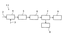
- a process for purifying gas obtained by gasifying coal has a CO shift process in which CO (carbon monoxide) is reacted with water to convert it into H 2 (hydrogen molecules) and CO 2 (carbon dioxide) ( Formula 1). Further, as an example of the process for purifying coal gasification gas, a process configuration in which the raw material gas after dedusting is supplied to the CO shift reactor as shown in FIG. 1 can be considered, and as shown in FIG. A process configuration having a recovery device that removes sulfur (such as H 2 S) in the upstream of the reactor is conceivable.
- refined gas obtained by gasifying and purifying coal has been proposed for use in synthesis of chemical products such as methanol and ammonia, or for direct power generation.
- Examples include a power generation (Integrated coal. Gasification Combination Cycle: IGCC) system (for example, Patent Document 1). Specifically, this is a system in which coal is converted into a combustible gas in a high-temperature and high-pressure gasification furnace, and the gasification gas is used as fuel to generate power by combining a gas turbine and a steam turbine.
- IGCC Integrated coal. Gasification Combination Cycle
- a CO shift catalyst (hereinafter referred to as “Co ⁇ ”) having molybdenum and cobalt as active components and alumina oxide supporting the active components as a support. It may be referred to as “Mo / Al 2 O 3 catalyst”).
- This Co—Mo / Al 2 O 3 catalyst has high activity at a high temperature (about 350 ° C. to about 500 ° C.).
- the catalyst performance due to carbonaceous precipitation (coking) decreases.
- there is a disadvantage in the system that the CO conversion rate is lowered due to chemical equilibrium.
- the present inventor has reviewed the reaction mechanism of the CO shift reaction, the configuration of the reaction apparatus, and the reaction method. As a result, it has been found that when a CO shift catalyst for coal gasification gas containing Mo, such as a Ni—Mo / TiO 2 catalyst, is used, the temperature of the reactor affects the catalyst activity. Since the CO shift reaction is an exothermic reaction, we consider that the CO shift reaction affects the temperature change of the reactor, and based on this knowledge, we focused on the temperature behavior of the reactor that changes according to the CO shift reaction. went. As a result, the gas obtained by gasifying the coal by the CO shift reaction is heated, and the heated gas heats the catalyst of the reactor and raises the temperature of the catalyst.
- Mo such as a Ni—Mo / TiO 2 catalyst
- the first embodiment according to the present invention is a CO shift reaction device for reforming carbon monoxide in a gas, which is a CO shift catalyst containing molybdenum, a gas introduction port for introducing gas, and the CO A reactor having at least a CO shift catalyst layer filled with a shift catalyst and through which the introduced gas passes; and a gas outlet for discharging the gas that has passed through the CO shift catalyst layer; and the CO shift catalyst layer A CO shift reaction apparatus comprising at least a cooling means for cooling.
- a second aspect of the present invention is a CO shift reaction method using the CO shift reaction apparatus of the first aspect, wherein the temperature of the CO shift catalyst is maintained at 350 ° C. or less by the cooling means.
- a third aspect of the present invention is a CO shift reaction apparatus for reforming carbon monoxide in a gas, comprising a CO shift catalyst containing molybdenum, a gas inlet for introducing gas, and the CO shift catalyst
- a plurality of adiabatic reactors including at least a CO shift catalyst layer through which the introduced gas passes, and a gas outlet for discharging the gas that has passed through the CO shift catalyst layer, and from the gas outlet
- It is a CO shift reaction apparatus characterized by including at least.
- a CO shift reaction method using the CO shift reaction device wherein at least the water vapor supply means is used to supply water vapor to the CO shift catalyst layer.
- the CO shift reaction method is characterized in that the temperature of the CO shift catalyst is maintained at 350 ° C. or lower.
- the CO shift reaction apparatus and the CO shift reaction method using the CO shift reaction apparatus of the present invention it is possible to suppress coking on the Ni—Mo / TiO 2 catalyst and extend the life of the catalyst.
- FIG. Schematic of the entire gas purification process.
- the schematic of the whole gas purification process of the aspect different from FIG. Sectional drawing which shows the one aspect
- the schematic diagram which shows the CO shift reaction apparatus using the adiabatic reactor of the aspect different from FIG. The schematic diagram which shows the CO shift reaction apparatus using the adiabatic reactor of the aspect different from this invention.
- FIG. The figure which shows the temperature measurement result of the CO shift catalyst of Example 2.
- the CO shift reaction apparatus of the present invention is an apparatus for reforming carbon monoxide in a gas as shown in the above formula (1).
- the target gas contains carbon monoxide and may be any one for the purpose of reforming it, such as CO and H 2 flammable gas obtained by adding oxygen or water vapor to coal. Can be mentioned.
- the CO shift reaction apparatus has at least a reactor and a cooling means.
- the reactor includes at least a gas introduction port, a CO shift catalyst layer filled with a CO shift catalyst, and a gas discharge port, and the gas is introduced from the gas introduction port into the reactor, and the CO shift catalyst layer is provided.
- the CO shift reaction proceeds by passing, and is then discharged out of the reactor through the gas outlet.
- the CO shift catalyst filled in the CO shift catalyst layer is a CO shift catalyst for refining coal gasification gas containing Mo.
- the CO shift catalyst preferably contains nickel, and more preferably uses titanium oxide as a carrier. Examples of such a preferable catalyst include a Ni—Mo / TiO 2 catalyst having low temperature activity.
- Mo which is the main component can promote the CO shift reaction in the presence of H 2 S.
- the chemical equilibrium formula of the Ni—Mo / TiO 2 catalyst during the catalyst sulfidation will be described with reference to the formula (2) showing a reaction in which molybdenum oxide reacts with hydrogen sulfide to become molybdenum sulfide.
- the CO shift catalyst when the catalyst is active is in a mixed state of molybdenum oxide and molybdenum sulfide.
- Le Chatelier's law if the H 2 S partial pressure in the reactor is small, the equilibrium composition is tilted to the left in the above formula (2), so that the proportion of molybdenum sulfide decreases and the catalytic activity tends to decrease.
- the cooling means provided in the CO shift reaction apparatus may be any means that can cool the CO shift catalyst layer so that the catalyst temperature does not become high.
- a means for water-cooling the periphery of the CO shift catalyst layer or other cooling medium may be used. Means for use and cooling may be mentioned.
- CO shift reaction devices such as water vapor supply means, cooling gas supply means, instruments (temperature sensor, concentration sensor, pressure sensor), backup CO shift reactor, and nitrogen supply in the event of an abnormality Can also be provided.
- the water vapor supply means may be any means that can supply water necessary for the CO shift reaction to the CO shift catalyst layer in the state of water vapor suitable for the reaction, and examples thereof include a water vapor supply device. .
- the temperature of the CO shift catalyst it is preferable to keep the temperature of the CO shift catalyst at 350 ° C. or lower by controlling the cooling means. This is because the CO shift catalyst for refining coal gasification gas containing Mo can be used for a long time.
- the CO shift reaction apparatus includes a plurality of adiabatic reactors, at least one heat exchange means, at least one water vapor supply means, and at least one gas pipe.
- the adiabatic reactor includes a gas inlet for introducing gas into the reactor, a CO shift catalyst layer filled with a CO shift catalyst and through which the introduced gas passes, and the gas that has passed through the CO shift catalyst layer outside the reactor. And at least a gas discharge port. If the CO shift reaction is completed in one adiabatic reactor, the CO shift catalyst becomes too hot due to the exothermic reaction.
- the CO shift catalyst of each adiabatic reactor is prevented from becoming too hot.
- Any heat exchange means may be used as long as it cools the gas that has become high temperature due to the CO shift reaction, and examples thereof include a heat exchanger.
- the gas cooled by the heat exchange means is introduced into the adiabatic reactor different from the above through the gas pipe connecting the adiabatic reactors in series, and then passes through the CO shift catalyst layer.
- the CO shift reaction is promoted.
- the gas to be reformed, the CO shift catalyst, and the water vapor supply means are as described above.
- CO shift reaction device it is also possible to provide devices and means such as instruments (temperature sensor, concentration sensor, pressure sensor), backup CO shift reactor, and nitrogen supply when an abnormality occurs.
- instruments temperature sensor, concentration sensor, pressure sensor, backup CO shift reactor, and nitrogen supply when an abnormality occurs.
- the CO shift reaction which is an exothermic reaction
- the CO shift reaction is controlled by adjusting the amount of water vapor supplied to the CO shift catalyst layer using a water vapor supply means, It is preferable to keep the temperature of the CO shift catalyst at 350 ° C. or lower by cooling the gas so that the gas discharged from the gas outlet becomes 350 ° C. or lower using heat exchange means. This is because the CO shift catalyst for refining coal gasification gas containing Mo can be used for a long time.
- FIG. 1 is an overall schematic view of the gas purification process 1-1.
- the coal 2 is first gasified in the gasifier 4 in the presence of oxygen 3.
- the CO shift reaction is performed by the CO shift reaction device 6, and then H 2 S and CO 2 in the gas are recovered by the H 2 S and CO 2 recovery device 7.
- a chemical product synthesis 8 such as methanol or ammonia, or introduced into a gas turbine or a steam turbine to generate electricity 9.
- FIG. 2 is an overall schematic view of a gas purification process having a mode different from that in FIG.
- the same steps as in the process of FIG. 1 are performed until the step of removing dust, but after that, the COS is converted into H 2 S by the COS converter 10 to convert H 2 S and CO 2 into H 2 S and CO 2.
- the CO shift reaction is performed by the CO shift reaction device 6.
- chemical synthesis 8 or power generation 9 is performed as in FIG.
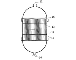
- FIG. 3 is a cross-sectional view showing one embodiment of the CO shift reaction apparatus 6 of the present invention in the CO shift process shown in FIGS.
- the CO shift reaction apparatus has a gas inlet 12, a CO shift catalyst layer 13, a gas outlet 14, and water 15 as basic components, and includes a tube plate 16 and a baffle 17 that reinforce the CO shift catalyst layer 13.
- the target gas is introduced into the reactor from the gas inlet 12, the CO shift reaction is promoted in the CO shift catalyst layer 13 in which the CO shift catalyst is filled in the tubular reaction tube, and then the gas outlet 14 It is discharged out of the reactor.
- the CO shift catalyst layer 13 is cooled by circulating water 15. Water vapor necessary for the CO shift reaction is introduced into the reaction apparatus from the gas inlet 12 together with the gas. It is possible to adjust the temperature of the CO shift catalyst by controlling the circulation amount of the water 15 in accordance with the CO shift reaction.
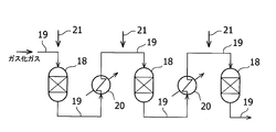
- FIG. 4 is a schematic view showing a CO shift reaction apparatus using an adiabatic reactor having a mode different from that shown in FIG.
- a plurality of adiabatic reactors 18 are connected in series by a gas pipe 19, and a heat exchange means 20 is provided in the middle of the gas pipe.
- the hot gas discharged from the adiabatic reactor is introduced into the next adiabatic reactor through the gas pipe, it is cooled by the heat exchange means and introduced into the next adiabatic reactor.
- the steam 21 is supplied from the steam supply means and introduced into the adiabatic reactor 18.
- FIG. 5 is a schematic view showing a CO shift reaction apparatus using an adiabatic reactor, which is different from the present invention. Unlike FIG. 4, since the CO shift reaction is completed by one adiabatic reactor 18, the CO shift catalyst becomes too hot due to the exothermic reaction, which affects the life of the CO shift catalyst.
- Titanium oxide (TiO 2 ) (“MC-90” manufactured by Ishihara Sangyo Co., Ltd.) is put into a 100 g porcelain dish, and nickel nitrate hexahydrate and ammonium molybdate tetrahydrate dissolved in 150 ml of water are finally obtained. After adding so that 5 mass% of NiO and 15 mass% of MoO 3 were supported with respect to the total amount of powder obtained, it was impregnated by evaporation to dryness on a porcelain dish. The obtained powder was completely dried with a dryer and then calcined at 500 ° C. for 3 hours (temperature increase rate: 100 ° C./h) to obtain a powder catalyst. The obtained powder was fixed with a 30-ton pressure molding machine, then crushed so that the particle diameter was in the range of 2 to 4 mm, and sieved to obtain a Ni—Mo / TiO 2 catalyst.
- Example 1 Evaluation was performed using the CO shift reaction apparatus shown in FIG.
- a CO shift catalyst was filled in the tubular reaction tube and the CO shift reaction was performed, water 15 was circulated around the tubular reaction tube to cool it with water.
- the target gas is introduced into the reactor from the gas inlet with water vapor, and the CO conversion rate is calculated from the change in the flow rate of the CO gas discharged from the gas inlet and the gas outlet according to the following equation (3). Calculated.
- the lifetime of the CO shift catalyst was evaluated by dividing the CO conversion rate after the gas was passed for 2000 hours by the CO conversion rate at the beginning of the gas flow.
- the temperature of the CO shift catalyst was evaluated by measuring the temperature of the CO shift catalyst layer.
- quantitative analysis of the carbonaceous matter in the catalyst was carried out using a carbon-sulfur simultaneous analyzer.
- Example 2 The three adiabatic reactors 18 of the CO shift reaction apparatus shown in FIG. 4 were prepared by filling a CO shift catalyst.
- the target gas is mixed with water vapor 21 in the gas pipe 19, introduced into the adiabatic reactor from the gas inlet, and CO-shifted, and newly supplied from the gas outlet to the next adiabatic reactor via the gas pipe. It was made to be mixed with water vapor 21 and introduced.
- the high-temperature gas discharged from the adiabatic reactor is cooled by the heat exchange means 20 when introduced into the next adiabatic reactor through the gas pipe, and is introduced into the next adiabatic reactor.
- the temperature of the CO shift catalyst in the adiabatic reactor was maintained at 350 ° C. or lower.
- the composition of the gas and water vapor mixture, the gas pressure, the gas temperature, and the temperature measurement method of the CO shift catalyst were the same as in Example 1, and GHSV is the total amount of catalyst charged in three adiabatic reactors, 3000 h ⁇ 1 was filled.
- the CO conversion rate is calculated from the following equation (2) from the change in the flow rate of CO gas discharged from the gas inlet of the adiabatic reactor where gas is first introduced and the gas outlet of the adiabatic reactor where gas is finally discharged. It was calculated by the formula shown in 3).
- the lifetime of the CO shift catalyst was evaluated by dividing the CO conversion rate after flowing the gas for 2000 hours by the CO conversion rate at the beginning of the gas flow.
- the carbonaceous carbon in the catalyst was quantitatively analyzed with a carbon-sulfur simultaneous analyzer.
- Example 1 Unlike Example 2, the CO shift reaction was performed using only one adiabatic reactor 18 without using cooling means or heat exchange means.
- the catalyst charge amount of the CO shift catalyst in the adiabatic reactor, the composition of the mixture of gas and water vapor, gas pressure, and gas temperature are the same as in Example 2.
- the CO shift catalyst life evaluation method, temperature measurement method, and carbonaceous precipitation amount calculation method were also the same as in Example 1.
- Table 1 shows the value obtained by dividing the CO conversion rate after 2000 hours of gas circulation in each example by the CO conversion rate at the initial stage of gas flow, and the increase in carbonaceous matter in the catalyst after 2000 hours of CO shift reaction. This is a result showing the quantity.
- the decrease in the CO conversion rate was extremely small as compared with Comparative Example 1, and the amount of precipitated carbonaceous matter was also small, so that carbonaceous precipitation was suppressed and the life was extended.
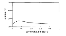
- It was. 6 to 8 show the temperature measurement results of the CO shift catalysts of Examples 1 and 2 and Comparative Example 1.
- the temperature when the horizontal axis is 0 indicates the catalyst temperature of the first part of the CO shift catalyst layer in which the target gas is introduced from the gas inlet and comes into contact with the CO shift catalyst layer.
- the temperature indicates the catalyst temperature of the last part of the CO shift catalyst layer where the gas generated by the CO shift catalyst layer finishes passing through the CO shift catalyst layer.
- the catalyst temperature was maintained at 350 ° C. or lower (FIGS. 6 and 7).
- the catalyst temperature rose to 450 ° C. due to CO shift reaction, that is, exothermic reaction (FIG. 8). ). From the results shown in Table 1 and FIGS. 6 to 8, it is clear that the life of the catalyst was extended by keeping the catalyst temperature at 350 ° C. or lower.
- the decrease in catalytic activity due to carbonaceous precipitation of the CO shift catalyst for refining coal gasification gas containing Mo is suppressed. Since it can extend the life, it is industrially useful.
Landscapes
- Chemical & Material Sciences (AREA)
- Chemical Kinetics & Catalysis (AREA)
- Organic Chemistry (AREA)
- Engineering & Computer Science (AREA)
- Combustion & Propulsion (AREA)
- Materials Engineering (AREA)
- Inorganic Chemistry (AREA)
- General Health & Medical Sciences (AREA)
- Health & Medical Sciences (AREA)
- General Chemical & Material Sciences (AREA)
- Oil, Petroleum & Natural Gas (AREA)
- Industrial Gases (AREA)
- Catalysts (AREA)
- Carbon And Carbon Compounds (AREA)
Abstract
Description
また、石炭ガス化ガスの精製プロセスには、一例として図1のように、脱塵後の原料ガスをCOシフト反応器に供給するプロセス構成が考えられ、また、図2のように、COシフト反応器前流に硫黄分(H2S等)を除去する回収装置を有するプロセス構成が考えられる。

過剰な添加水蒸気量の低減を目的として、低温(200~350℃程度)でも高い活性を有する、モリブデン及びニッケルを活性成分とし、当該活性成分を担持する酸化チタンを担体とするCOシフト触媒(以下、「Ni-Mo/TiO2触媒」とする場合がある。)が提案されている(特許文献2)。しかし、COシフト反応は発熱反応であるため、一般的な断熱反応器を使用すれば、反応器出口付近では高温となり(450~550℃程度)、コーキングによる触媒耐久性低下や、化学平衡上の不利が解消されない。
そうしたところ、Ni-Mo/TiO2触媒をはじめとしたMoを含有する石炭ガス化ガス用のCOシフト触媒を用いた場合に、反応装置の温度が触媒活性に影響するという知見を得た。COシフト反応は発熱反応であることから、COシフト反応が反応装置の温度変化に影響すると考え、かかる知見を基に、COシフト反応に応じて変化する反応装置の温度挙動に着目し、検討を行った。その結果、COシフト反応によって石炭をガス化したガスが加熱され、これにより高温となったガスが反応装置の触媒を加熱して触媒の温度を上昇させるという加熱の連鎖により、触媒の温度が所定温度を超えてしまうことでコーキング量が増加し、触媒の寿命に影響することがわかった。
この結果を踏まえ、種々の検討を行ったところ、COシフト反応により上昇するガス温度を制御することにより、触媒温度を所定温度以下とすれば、Ni-Mo/TiO2触媒をはじめとしたMoを含有する石炭ガス化ガス用のCOシフト触媒が長寿命化することを見出し、本発明を完成するに至った。
まず、本発明のCOシフト反応装置は、上記式(1)に示すように、ガス中の一酸化炭素を改質する装置である。対象となるガスは、一酸化炭素を含み、これを改質する目的のものであればよく、石炭に酸素や水蒸気等を加えて得られるCOとH2を主成分とする可燃性ガス等が挙げられる。
そして、COシフト反応装置は、反応器と、冷却手段とを少なくとも備える構成となっている。反応器は、ガス導入口と、COシフト触媒が充填されたCOシフト触媒層と、ガス排出口とを少なくとも備え、上記ガスは、ガス導入口から反応器内へ導入され、COシフト触媒層を通過することによりCOシフト反応が進み、その後ガス排出口から反応器の外へ排出される。

COシフト反応装置は、複数の断熱反応器と、少なくとも1つの熱交換手段と、少なくとも1つの水蒸気供給手段と、少なくとも1つのガス管とを少なくとも備える構成となっている。
断熱反応器は、反応器内へガスを導入するガス導入口と、COシフト触媒が充填され、導入されたガスが通過するCOシフト触媒層と、COシフト触媒層を通過したガスを反応器外へ排出するガス排出口とを少なくとも備える。1つの断熱反応器でCOシフト反応を完了させてしまうと、発熱反応によりCOシフト触媒が高温となりすぎてしまう。そこで、COシフト反応を複数の断熱反応器で分散して行う構成を採用することにより、各断熱反応器のCOシフト触媒が高温となりすぎてしまうことを防止している。
熱交換手段は、COシフト反応により高温となったガスを冷却するものであればよく、熱交換器等が挙げられる。熱交換手段にて冷却されたガスは、断熱反応器を直列に連結するガス管を通って上記とは異なる断熱反応器へガス導入口より導入され、COシフト触媒層を通過することにより、次のCOシフト反応が促進されることとなる。
改質対象であるガス、COシフト触媒、水蒸気供給手段については、上記したとおりである。
対象となるガスは、ガス導入口12から反応装置内へ導入され、管型反応管内にCOシフト触媒が充填されたCOシフト触媒層13にてCOシフト反応が促進され、その後ガス排出口14から反応装置外へ排出される。COシフト触媒層13の周囲は、水15が循環することでCOシフト触媒層13を冷却する仕組みとなっている。COシフト反応に必要な水蒸気は、ガスと共にガス導入口12から反応装置内へ導入される。COシフト反応に応じて水15の循環量を制御することにより、COシフト触媒の温度を調整することが可能である。
断熱反応器から排出された高温のガスは、ガス管を通って次の断熱反応器へ導入される際に熱交換手段によって冷却されて、次の断熱反応器へ導入される。熱交換手段20と断熱反応器18との間のガス管で、水蒸気供給手段から水蒸気21が供給され、断熱反応器18へ導入される仕組みとなっている。
酸化チタン(TiO2)(石原産業製「MC-90」)を100g磁製皿に入れ、150mlの水に溶かした硝酸ニッケル・6水和物とモリブデン酸アンモニウム・4水和物を、最終的に得られる全粉末量に対してNiOが5質量%、MoO3が15質量%担持されるように添加後、磁製皿上で蒸発乾固含浸した。得られた粉末を乾燥器で完全に乾燥させた後、500℃で3時間焼成(昇温速度100℃/h)を施すことにより粉末触媒を得た。
得られた粉末を30tonの加圧成形器で粉末を固定化させた後、粒子径が2~4mmの範囲となるように破砕後、ふるい分けして、Ni-Mo/TiO2触媒を得た。
評価は、図3に示すCOシフト反応装置を用いて行った。管型反応管にCOシフト触媒を充填し、COシフト反応を行う際は、管型反応管の周囲を水15を循環させて水冷した。対象となるガスは、水蒸気と共にガス導入口から反応器内へ導入し、ガス導入口とガス排出口から排出されるCOガスの流量変化から、下記式(3)に示す式によりCO転化率を算出した。反応器に導入されるガスと水蒸気との混合物の組成は、H2/CO/CO2/H2O=17/24/11/48モル%、GHSV(単位触媒量あたりのガス量)=3000h-1、H2S=20ppm、S/CO=1.0とし、ガス圧力を0.9MPa、ガス温度を250℃とした。
COシフト触媒の寿命は、2000時間ガスを流通させた後のCO転化率を、ガス流通初期のCO転化率で除することにより評価した。COシフト触媒の温度は、COシフト触媒層の温度を測定することにより評価した。また、触媒上の炭素質析出量を分析するために,炭素硫黄同時分析装置にて,触媒中の炭素質の定量分析を実施した。

図4に示すCOシフト反応装置の3つの断熱反応器18に、COシフト触媒を充填したものを準備した。対象となるガスは、ガス管19にて水蒸気21と混合され、ガス導入口から断熱反応器内へ導入されてCOシフト反応し、ガス排出口からガス管を介して次の断熱反応器へ新たな水蒸気21と混合されて導入されるようにした。断熱反応器から排出された高温のガスは、ガス管を通って次の断熱反応器へ導入される際に熱交換手段20によって冷却されて、次の断熱反応器へ導入される仕組みとし、各断熱反応器のCOシフト触媒の温度を350℃以下に保持した。ガスと水蒸気との混合物の組成、ガス圧力、ガス温度およびCOシフト触媒の温度測定方法は、実施例1と同条件とし、GHSVは、3つの断熱反応器に充填した合計触媒量で、3000h-1となるように充填した。また、CO転化率は、最初にガスが導入される断熱反応器のガス導入口と、最後にガスを排出する断熱反応器のガス排出口から排出されるCOガスの流量変化から、下記式(3)に示す式により算出した。COシフト触媒の寿命は、実施例1と同様に、2000時間ガスを流通させた後のCO転化率を、ガス流通初期のCO転化率で除することにより評価した。
また、触媒上の炭素質析出量を分析するために、炭素硫黄同時分析装置にて,触媒中の炭素質の定量分析を実施した。
実施例2とは異なり、冷却手段や熱交換手段を用いることなく、1つの断熱反応器18のみを用いてCOシフト反応を行った。断熱反応器へのCOシフト触媒の触媒充填量、ガスと水蒸気との混合物の組成、ガス圧力、ガス温度は、実施例2と同条件である。また、COシフト触媒の寿命評価方法、温度測定方法および炭素質析出量の算出方法についても、実施例1と同方法とした。

図6~8は、実施例1、2および比較例1のCOシフト触媒の温度測定結果を示したものである。横軸が0の場合の温度は、対象ガスがガス導入口から導入されCOシフト触媒層へ接触する、COシフト触媒層の最初の部分の触媒温度を示しており、横軸が1の場合の温度は、COシフト触媒層によって発熱するガスがCOシフト触媒層を通過し終える、COシフト触媒層の最後の部分の触媒温度を示している。実施例1、2では、触媒温度は350℃以下に保持されているところ(図6、7)、比較例1では、COシフト反応すなわち発熱反応により、触媒温度が450℃まで上昇した(図8)。
表1と図6~8の結果からみて、触媒温度を350℃以下に保持することで、触媒が長寿命化したことは明らかである。
1-2 ガス精製プロセス
2 石炭
3 酸素
4 ガス化炉
5 脱塵装置
6 COシフト反応装置
7 H2S/CO2回収装置
8 化成品合成
9 発電
10 COS変換装置
12 ガス導入口
13 COシフト触媒層
14 ガス排出口
15 水
16 管板
17 バッフル
18 断熱反応器
19 ガス管
20 熱交換手段
21 水蒸気
Claims (8)
- ガス中の一酸化炭素を改質するCOシフト反応装置であって、
モリブデンを含有するCOシフト触媒と、
ガスを導入するガス導入口と、前記COシフト触媒が充填され、前記導入されたガスが通過するCOシフト触媒層と、前記COシフト触媒層を通過したガスを排出するガス排出口と、を少なくとも備える反応器と、
前記COシフト触媒層を冷却する冷却手段と
を少なくとも備えることを特徴とするCOシフト反応装置。 - 前記COシフト触媒が、さらにニッケルを含有する請求項1記載のCOシフト反応装置。
- 前記COシフト触媒が、酸化チタンを担体とする請求項1または2記載のCOシフト反応装置。
- 請求項1~3のいずれかに記載のCOシフト反応装置を用いたCOシフト反応方法であって、
前記冷却手段により、前記COシフト触媒の温度を350℃以下に保持することを特徴とするCOシフト反応方法。 - ガス中の一酸化炭素を改質するCOシフト反応装置であって、
モリブデンを含有するするCOシフト触媒と、
ガスを導入するガス導入口と、前記COシフト触媒が充填され、前記導入されたガスが通過するCOシフト触媒層と、前記COシフト触媒層を通過したガスを排出するガス排出口と、を少なくとも備える複数の断熱反応器と、
前記ガス排出口から排出されたガスを冷却する少なくとも1つの熱交換手段と、
前記COシフト触媒層に水蒸気を供給する少なくとも1つの水蒸気供給手段と、
前記複数の断熱反応器を直列に連結する少なくとも1つのガス管と
を少なくとも備えることを特徴とするCOシフト反応装置。 - 前記COシフト触媒が、さらにニッケルを含有する請求項5記載のCOシフト反応装置。
- 前記COシフト触媒が、酸化チタンを担体とする請求項5または6記載のCOシフト反応装置。
- 請求項5~7のいずれかに記載のCOシフト反応装置を用いたCOシフト反応方法であって、
少なくとも、前記水蒸気供給手段を用いて、前記COシフト触媒層への水蒸気の供給量を調整することによりCOシフト反応を制御し、かつ、
前記熱交換手段を用いて、前記ガス排出口から排出されたガスが350℃以下となるように当該ガスを冷却することにより、
前記COシフト触媒の温度を350℃以下に保持することを特徴とするCOシフト反応方法。
Priority Applications (2)
| Application Number | Priority Date | Filing Date | Title |
|---|---|---|---|
| US14/366,588 US20140346403A1 (en) | 2011-12-22 | 2012-12-13 | Carbon monoxide shift reaction apparatus and carbon monoxide shift reaction method |
| AU2012354919A AU2012354919B2 (en) | 2011-12-22 | 2012-12-13 | CO shift reaction apparatus and CO shift reaction method |
Applications Claiming Priority (2)
| Application Number | Priority Date | Filing Date | Title |
|---|---|---|---|
| JP2011281522A JP2013129787A (ja) | 2011-12-22 | 2011-12-22 | Coシフト反応装置およびcoシフト反応方法 |
| JP2011-281522 | 2011-12-22 |
Publications (1)
| Publication Number | Publication Date |
|---|---|
| WO2013094512A1 true WO2013094512A1 (ja) | 2013-06-27 |
Family
ID=48668404
Family Applications (1)
| Application Number | Title | Priority Date | Filing Date |
|---|---|---|---|
| PCT/JP2012/082329 Ceased WO2013094512A1 (ja) | 2011-12-22 | 2012-12-13 | Coシフト反応装置およびcoシフト反応方法 |
Country Status (4)
| Country | Link |
|---|---|
| US (1) | US20140346403A1 (ja) |
| JP (1) | JP2013129787A (ja) |
| AU (1) | AU2012354919B2 (ja) |
| WO (1) | WO2013094512A1 (ja) |
Cited By (2)
| Publication number | Priority date | Publication date | Assignee | Title |
|---|---|---|---|---|
| CN109279573A (zh) * | 2018-09-30 | 2019-01-29 | 中石化宁波工程有限公司 | 一种配套水煤浆气化的等温变换工艺 |
| CN115784150A (zh) * | 2022-11-01 | 2023-03-14 | 山东明泉新材料科技有限公司 | 一种绝热变换炉的炉温控制方法 |
Families Citing this family (1)
| Publication number | Priority date | Publication date | Assignee | Title |
|---|---|---|---|---|
| CN115924844B (zh) * | 2022-10-30 | 2025-01-28 | 贵州黔希化工有限责任公司 | 一种绝热变换炉新旧催化剂同时装填方法 |
Citations (5)
| Publication number | Priority date | Publication date | Assignee | Title |
|---|---|---|---|---|
| JPS61222903A (ja) * | 1985-03-05 | 1986-10-03 | インペリアル・ケミカル・インダストリーズ・ピーエルシー | 水素及び炭素酸化物類を含むガス流の製造方法及びそのための装置 |
| JPH0374493A (ja) * | 1989-08-15 | 1991-03-29 | Ishii Iron Works Co Ltd | 都市ガス製造プラントの一酸化炭素変成法およびその装置 |
| JPH06172760A (ja) * | 1992-12-10 | 1994-06-21 | Ube Ind Ltd | 多段冷却型ガス反応装置 |
| JP2002060205A (ja) * | 2000-06-08 | 2002-02-26 | Toyota Motor Corp | 燃料改質装置 |
| WO2011105501A1 (ja) * | 2010-02-24 | 2011-09-01 | 三菱重工業株式会社 | Coシフト触媒、coシフト反応装置及びガス化ガスの精製方法 |
Family Cites Families (2)
| Publication number | Priority date | Publication date | Assignee | Title |
|---|---|---|---|---|
| US6306354B1 (en) * | 1996-05-17 | 2001-10-23 | International Fuel Cells, Llc | Shift converter |
| US20060228284A1 (en) * | 2005-04-11 | 2006-10-12 | Schmidt Craig A | Integration of gasification and ammonia production |
-
2011
- 2011-12-22 JP JP2011281522A patent/JP2013129787A/ja active Pending
-
2012
- 2012-12-13 WO PCT/JP2012/082329 patent/WO2013094512A1/ja not_active Ceased
- 2012-12-13 AU AU2012354919A patent/AU2012354919B2/en not_active Ceased
- 2012-12-13 US US14/366,588 patent/US20140346403A1/en not_active Abandoned
Patent Citations (5)
| Publication number | Priority date | Publication date | Assignee | Title |
|---|---|---|---|---|
| JPS61222903A (ja) * | 1985-03-05 | 1986-10-03 | インペリアル・ケミカル・インダストリーズ・ピーエルシー | 水素及び炭素酸化物類を含むガス流の製造方法及びそのための装置 |
| JPH0374493A (ja) * | 1989-08-15 | 1991-03-29 | Ishii Iron Works Co Ltd | 都市ガス製造プラントの一酸化炭素変成法およびその装置 |
| JPH06172760A (ja) * | 1992-12-10 | 1994-06-21 | Ube Ind Ltd | 多段冷却型ガス反応装置 |
| JP2002060205A (ja) * | 2000-06-08 | 2002-02-26 | Toyota Motor Corp | 燃料改質装置 |
| WO2011105501A1 (ja) * | 2010-02-24 | 2011-09-01 | 三菱重工業株式会社 | Coシフト触媒、coシフト反応装置及びガス化ガスの精製方法 |
Cited By (3)
| Publication number | Priority date | Publication date | Assignee | Title |
|---|---|---|---|---|
| CN109279573A (zh) * | 2018-09-30 | 2019-01-29 | 中石化宁波工程有限公司 | 一种配套水煤浆气化的等温变换工艺 |
| CN109279573B (zh) * | 2018-09-30 | 2022-03-22 | 中石化宁波工程有限公司 | 一种配套水煤浆气化的等温变换工艺 |
| CN115784150A (zh) * | 2022-11-01 | 2023-03-14 | 山东明泉新材料科技有限公司 | 一种绝热变换炉的炉温控制方法 |
Also Published As
| Publication number | Publication date |
|---|---|
| AU2012354919B2 (en) | 2016-01-21 |
| US20140346403A1 (en) | 2014-11-27 |
| JP2013129787A (ja) | 2013-07-04 |
| AU2012354919A1 (en) | 2014-08-07 |
Similar Documents
| Publication | Publication Date | Title |
|---|---|---|
| JP5009419B2 (ja) | タール含有ガスの改質用触媒の製造方法、タール改質方法及びタール含有ガスの改質用触媒の再生方法 | |
| Cho et al. | Carbon formation on nickel and iron oxide-containing oxygen carriers for chemical-looping combustion | |
| EP2236204B1 (en) | Process for production of catalyst for use in the reforming of tar-containing gas, method for reforming of tar, and method for regeneration of catalyst for use in the reforming of tar-containing gas | |
| Song et al. | Nitrogen transfer of fuel-N in chemical looping combustion | |
| JP5494135B2 (ja) | タール含有ガスの改質用触媒及びその製造方法、並びにタール含有ガスの改質方法 | |
| JP5659537B2 (ja) | タール含有ガスの改質用触媒及びその製造方法、並びにタール含有ガスの改質方法 | |
| JP5780271B2 (ja) | タール含有ガスの改質用触媒及びその製造方法、並びにタール含有ガスの改質方法 | |
| BRPI1010991B1 (pt) | "catalisador para reformar gás contendo alcatrão, método para preparar catalisador para reformar um gás contendo alcatrão, e método para regenerar catalisador para reformar um gás contendo alcatrão. | |
| Bock et al. | Experimental study on high-purity hydrogen generation from synthetic biogas in a 10 kW fixed-bed chemical looping system | |
| Quan et al. | Utilization of NiO/porous ceramic monolithic catalyst for upgrading biomass fuel gas | |
| Ran et al. | Evaluation of CuO/MgAl2O4 in biomass chemical looping gasification with oxygen uncoupling | |
| WO2013094512A1 (ja) | Coシフト反応装置およびcoシフト反応方法 | |
| JP6460879B2 (ja) | タール含有ガス改質用触媒の再生方法 | |
| JP2013173898A (ja) | Coシフト反応装置及びガス化ガス精製システム | |
| CN103946149B (zh) | 用于增加合成气的氢含量的方法 | |
| EP2711336B1 (en) | Non-co2 emitting manufacturing method for synthesis gas | |
| Yuan et al. | Biomass chemical looping gasification performance of a Ce-modified BaFe2O4 oxygen carrier | |
| US20130109766A1 (en) | Biomass gasification gas purification system and method, and methanol production system and method | |
| JP7679680B2 (ja) | 炭素生成システム及び炭素生成方法 | |
| Suyambazhahan | Experimental study of coconut shell fluidized bed gasification for production of fuel gas for end-use applications | |
| Fukuhara et al. | Multi-stage structured catalyst system for post-treatment of GHGs emitted from industrial processes | |
| GAS | S. RAPAGNA,* N. JAND and PU FOSCOLO | |
| JP2024157349A (ja) | 固体炭素析出システムおよび固体炭素の析出方法 | |
| WO2023120504A1 (ja) | 酸素キャリア、酸素キャリアの製造方法、ガスの製造方法及びガス製造装置 | |
| EP4551545A1 (en) | Improved process for the one-step conversion of carbon dioxide and renewable hydrogen to low-carbon methane |
Legal Events
| Date | Code | Title | Description |
|---|---|---|---|
| 121 | Ep: the epo has been informed by wipo that ep was designated in this application |
Ref document number: 12858913 Country of ref document: EP Kind code of ref document: A1 |
|
| WWE | Wipo information: entry into national phase |
Ref document number: 14366588 Country of ref document: US |
|
| NENP | Non-entry into the national phase |
Ref country code: DE |
|
| ENP | Entry into the national phase |
Ref document number: 2012354919 Country of ref document: AU Date of ref document: 20121213 Kind code of ref document: A |
|
| 122 | Ep: pct application non-entry in european phase |
Ref document number: 12858913 Country of ref document: EP Kind code of ref document: A1 |