WO2013089120A1 - Seal structure for flow-path connection part - Google Patents
Seal structure for flow-path connection part Download PDFInfo
- Publication number
- WO2013089120A1 WO2013089120A1 PCT/JP2012/082147 JP2012082147W WO2013089120A1 WO 2013089120 A1 WO2013089120 A1 WO 2013089120A1 JP 2012082147 W JP2012082147 W JP 2012082147W WO 2013089120 A1 WO2013089120 A1 WO 2013089120A1
- Authority
- WO
- WIPO (PCT)
- Prior art keywords
- receiving groove
- gasket
- seal structure
- flange
- flow path
- Prior art date
Links
Images


Classifications
-
- F—MECHANICAL ENGINEERING; LIGHTING; HEATING; WEAPONS; BLASTING
- F16—ENGINEERING ELEMENTS AND UNITS; GENERAL MEASURES FOR PRODUCING AND MAINTAINING EFFECTIVE FUNCTIONING OF MACHINES OR INSTALLATIONS; THERMAL INSULATION IN GENERAL
- F16L—PIPES; JOINTS OR FITTINGS FOR PIPES; SUPPORTS FOR PIPES, CABLES OR PROTECTIVE TUBING; MEANS FOR THERMAL INSULATION IN GENERAL
- F16L23/00—Flanged joints
- F16L23/16—Flanged joints characterised by the sealing means
- F16L23/18—Flanged joints characterised by the sealing means the sealing means being rings
- F16L23/22—Flanged joints characterised by the sealing means the sealing means being rings made exclusively of a material other than metal
-
- F—MECHANICAL ENGINEERING; LIGHTING; HEATING; WEAPONS; BLASTING
- F16—ENGINEERING ELEMENTS AND UNITS; GENERAL MEASURES FOR PRODUCING AND MAINTAINING EFFECTIVE FUNCTIONING OF MACHINES OR INSTALLATIONS; THERMAL INSULATION IN GENERAL
- F16J—PISTONS; CYLINDERS; SEALINGS
- F16J15/00—Sealings
- F16J15/02—Sealings between relatively-stationary surfaces
- F16J15/06—Sealings between relatively-stationary surfaces with solid packing compressed between sealing surfaces
- F16J15/10—Sealings between relatively-stationary surfaces with solid packing compressed between sealing surfaces with non-metallic packing
- F16J15/104—Sealings between relatively-stationary surfaces with solid packing compressed between sealing surfaces with non-metallic packing characterised by structure
- F16J15/106—Sealings between relatively-stationary surfaces with solid packing compressed between sealing surfaces with non-metallic packing characterised by structure homogeneous
-
- F—MECHANICAL ENGINEERING; LIGHTING; HEATING; WEAPONS; BLASTING
- F16—ENGINEERING ELEMENTS AND UNITS; GENERAL MEASURES FOR PRODUCING AND MAINTAINING EFFECTIVE FUNCTIONING OF MACHINES OR INSTALLATIONS; THERMAL INSULATION IN GENERAL
- F16K—VALVES; TAPS; COCKS; ACTUATING-FLOATS; DEVICES FOR VENTING OR AERATING
- F16K27/00—Construction of housing; Use of materials therefor
- F16K27/02—Construction of housing; Use of materials therefor of lift valves
-
- F—MECHANICAL ENGINEERING; LIGHTING; HEATING; WEAPONS; BLASTING
- F16—ENGINEERING ELEMENTS AND UNITS; GENERAL MEASURES FOR PRODUCING AND MAINTAINING EFFECTIVE FUNCTIONING OF MACHINES OR INSTALLATIONS; THERMAL INSULATION IN GENERAL
- F16L—PIPES; JOINTS OR FITTINGS FOR PIPES; SUPPORTS FOR PIPES, CABLES OR PROTECTIVE TUBING; MEANS FOR THERMAL INSULATION IN GENERAL
- F16L23/00—Flanged joints
- F16L23/04—Flanged joints the flanges being connected by members tensioned in the radial plane
- F16L23/08—Flanged joints the flanges being connected by members tensioned in the radial plane connection by tangentially arranged pin and nut
- F16L23/10—Flanged joints the flanges being connected by members tensioned in the radial plane connection by tangentially arranged pin and nut with a pivoting or swinging pin
Definitions
- the present invention relates to a seal structure (seal device) used for a connection portion of a flow path such as a pipe or a container.
- a flange joint using a flange (a disk-shaped enlarged portion formed at the end of the pipe) is known as a joint at a place where it is necessary to remove the pipe for sending a fluid.
- a seal gasket
- the gasket is mainly made of an elastic body, and is compression-fitted in a groove provided in the flange. And by the repulsive force by being compressed, it crimps
- Patent Documents 1 and 2 propose proposals for this problem.
- Patent Document 1 a tubular body connecting apparatus that joins connecting end portions of tubular bodies via a ring-shaped packing and tightens and fixes them with a clamp hand wound around the outer circumference of the joined portion.
- the connection end is formed with an annular abutting portion having a shape that makes direct contact with each other in the tube axis direction over the entire circumference by tightening the clamp hand and engages with each other in the tube axis direction.
- a flange having an end face extending in a radial direction substantially perpendicular to the axis of the pipe, a flange joined to the pipe end, a central circular opening passing through the end face and communicating with the inside of the pipe, and the flange as the axis.
- a flange connection having a device for clamping in alignment with each other in a direction, a sealing chamber formed by an annular recess formed circumferentially around the central circular opening of the flange and extending inward in the axial direction; And an elastic seal ring positioned in the seal chamber and compressed in the seal chamber, and the seal chamber and the elastic seal ring generate a sealing pressure by the seal chamber wall surface when the flange seal surface is directly engaged.
- an object of the present invention is to provide a seal structure for a flow path connection portion that does not require high dimensional accuracy (with normal dimensional accuracy) and can easily perform center alignment between the flow channel and the gasket.
- 1st invention is the seal structure of the flow-path connection part which has a pair of flange arrange
- the gasket which has the protruding part provided symmetrically in the front and back at the outer periphery or the outer periphery, and a ring in a connection surface
- a flange having a receiving groove provided on the protruding portion, the receiving groove being wider than the raised portion, and having an arcuate deepest portion with which the top of the raised portion abuts, the raised portion
- the top portion of the channel has a curved surface, and the curvature of the top portion is equal to or greater than the curvature of the deepest portion of the receiving groove.
- the inner portion of the raised portion of the gasket is clamped by the connecting surface of the flange, whereby the inner diameter of the gasket is the same as the inner diameter of the flange.
- the pair of flanges include a fitting portion on an outer peripheral side of the receiving groove.
- a fourth invention is characterized in that, in the first invention, the receiving groove has an inner surface of the receiving groove that contacts the outer peripheral surface of the gasket, and the inner surface of the receiving groove is a surface parallel to the central axis.
- 5th invention is a liquid discharge apparatus provided with the sealing structure of the flow-path connection part which concerns on 1st invention.
- 6th invention is a liquid storage container provided with the sealing structure of the flow-path connection part which concerns on 1st invention.
- the center of the flange and the gasket can be easily aligned without requiring high dimensional accuracy. Further, since the flange and the gasket are in contact at multiple points, a high sealing pressure can be realized.
- (a) is a case where the receiving groove and the fitting member are provided apart from each other, and (b) is a case where the fitting member is provided by removing a part of the receiving groove. It is a fragmentary sectional view showing a third embodiment valve. It is a fragmentary sectional view showing the tank lid concerning a fourth embodiment.
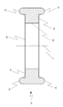
- FIG. 2 shows a cross-sectional shape of the gasket 3 according to the present embodiment.
- the gasket 3 of the present embodiment is an annular elastic body, and has a flat surface portion 5 and a raised portion 6 provided symmetrically on the front and back (in the same direction as the center 7) on the outer peripheral portion.
- the flat portion 5 is provided with a through hole 9 through which a fluid passes in the center.
- the diameter of the through-hole 9 is slightly larger than the inner diameter of the tube 1, and the gasket inner peripheral surface 8 and the inner peripheral surface of the tube 1 are located on the same plane in a state of being sandwiched and deformed between the tubes 1 and 1. It is supposed to be. By doing so, there is no step at the joint, so that sanitary properties can be maintained and the flow resistance can be reduced.
- the top of the raised portion 6 (surface in the same direction as the center 7) has a curved surface, and its cross section is semicircular or semielliptical.
- the annular raised portion 6 is provided symmetrically on the outer periphery or in the vicinity of the outer periphery so as to match the shape of the receiving groove 10. That is, the gasket 3 is configured symmetrically with respect to the center line in the direction orthogonal to the center 7.
- the curvature of the raised portion 6 is larger than the curvature of the concave surface of the receiving groove 10 (in other words, the radius is made smaller), and the rising (height) from the flat portion 5 is larger than the depth of the receiving groove 10. Yes.
- the reason why it is better to increase the curvature of the raised portion 6 is to facilitate centering, and the height is made larger than the depth of the groove 10 when the flange 2 is fixed. This is because the sealing force is obtained by utilizing the repulsive force generated when the raised portion 6 is crushed.
- rubber made of silicon, PTFE, nitrile or the like is used.
- the receiving groove 10 is provided on the joint surface side of the flange 2 provided at each pipe end.
- the receiving groove 10 according to the present embodiment has a semicircular or semi-elliptical cross-sectional shape, and is a recess provided in an annular shape on the joint surface of the flange 2.
- the curvature of the concave surface of the receiving groove 10 is made smaller (in other words, the radius is larger) than the curvature of the top of the raised portion 6. This is for realizing the centering action described later.
- the curvature of the entire concave surface does not need to be equal to or less than the curvature of the top of the raised portion 6, and at least the curvature around the deepest portion may be equal to or less than the curvature of the top of the raised portion 6.
- the depth of the receiving groove 10 is shallower than the height of the raised portion 6 of the gasket 3, and the width thereof is wider than the width of the raised portion 6 of the gasket 3. This is because the raised portion 6 of the gasket 3 is crushed when the flange 20 is fixed, and the repulsive force generated by the crushed is used to obtain the sealing pressure.
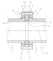
- FIG. 4 shows a state in which the tubes 1 having the flange 2 formed with the receiving groove 10 are joined by the clamp 4 with the gasket 3 interposed therebetween.
- the ends of the tubes 1 are not directly touched at the time of clamp joining, but the ends of the tubes 1 are directly touched to each other, and a receiving groove outer inner surface 18 described later is provided. Also good.
- the raised portion 6 of the gasket 3 is fitted into the deepest portion 12 of the receiving groove 10. In this state, the gasket center 7 and the tube center 14 are designed to be aligned.
- the raised portion 6 Since the height of the raised portion 6 is higher than the depth of the receiving groove 10, the raised portion 6 is crushed when the tubes 1 are fixed in a state of being fitted to the deepest portion 12 of the receiving groove 10. Furthermore, the center side end portions 13 and 13 on the connection surface side of the opposing flanges 2 and 2 are sandwiched while the flat portion 5 is crushed. Thereby, since the gasket 3 is crimped
- the flange 20 is used with a bolt and a nut. You may connect directly.
- the gasket center 7 and the tube center 14 are matched in the normal operation of connecting the tubes 1 to each other. Further, as can be seen from FIGS. 5A and 5B, the gasket 3 can be centered before being crushed by the center side end portion 13 and being crushed.
- the shape of the gasket raised portion and the receiving groove are mutually curved, so that the centers of the gasket and the tube can be naturally aligned. Therefore, strict dimensional accuracy is not required, and the manufacturing cost can be suppressed. Further, since the gasket is crushed and fixed at two locations of the deepest portion 12 and the center side end portion 13 and a sealing pressure is generated by a force against the pressure from the inside of the tube, a large sealing pressure can be generated.
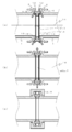
- the second embodiment is a seal structure that makes it easy to align the centers of the tubes 1 by making the tubes 1 “fit”, and enables the centers to be aligned more reliably.
- convex members 15 and 17 are alternately formed on the outer peripheral side of the receiving groove 10 provided in the flange 2, and an annular fitting portion 16 formed by fitting them is formed.
- the convex members 15 and 17 may be provided separately from the receiving groove 10 (FIG. 6A).
- the shape of the receiving groove 10 is 90 ° at the center angle.
- An arc shape may be used to reduce the size (FIG. 6B).
- the curvature around the deepest portion 12 of the receiving groove 10 is made smaller than the curvature of the curved surface of the gasket raised portion 6, the effect of centering can be naturally obtained when the pipe 1 is connected. Furthermore, by providing the fitting portion 16, the amount of collapse of the gasket 3 at the time of pipe joining becomes constant, and damage and deformation (plastic deformation) due to excessive crushing can be prevented.
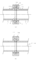
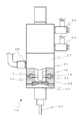
- the third embodiment discloses a case where a seal structure is used for a needle valve which is a kind of liquid ejection device, as an application example to a joint portion of a device that handles fluid.
- a valve it is suitable to be used for a flow path that communicates with a unit for a part that is frequently disassembled or replaced, for example, a discharge having a nozzle, a valve seat, or the like.
- the needle valve 19 of FIG. 7 drives a piston (not shown) to which the needle 21 is connected by air supplied and exhausted through the joint 20, and opens and closes the communication hole 24 at the needle tip 25.
- the liquid material is discharged from the nozzle 23.
- the liquid material is supplied from a liquid material supply port 26 that communicates with a liquid storage container (not shown).
- the gasket 3 and the receiving groove 10 are provided between the valve body 27 and the discharge unit 28 in which the valve seat 22 and the nozzle 23 are installed. Further, convex members that mesh with each other are provided on the outer peripheral side of the receiving groove 10 to form a fitting portion 16.
- the valve main body 27 and the discharge unit 28 are fixed by, for example, fixing a screw (bolt) at a portion where there is no gasket.
- seal structure of the present embodiment may be applied to a seam of the liquid material supply port 26 or a place that separates a piston storage chamber (not shown) from a fluid chamber where the valve tip is located.
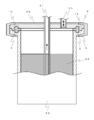
- the fourth embodiment discloses a case where a seal structure is used for the liquid storage container.
- the liquid storage container according to the present embodiment shown in FIG. 8 is a pressurized tank, and the lid 29 has a supply / exhaust port 30 for supplying and exhausting pressurized gas, and a liquid stored and pressurized in the tank 32.
- a suction pipe 31 for discharging the material 33 to the outside is disposed.
- the lid 29 and the tank 32 main body are fixed by providing the flange 2 at the upper end of the tank 32 and the outer edge of the lid 29 and sandwiching the flange 2 with the clamp 4 as shown in FIG.
- the gasket 3 and the receiving groove 10 are provided on the flange on the upper end of the tank 32 main body and the flange 2 on the outer edge of the lid portion 29.
- a convex member that meshes with the outer peripheral side of the receiving groove 10 is provided to form a fitting portion 16.
Abstract
Description
第2の発明は、第1の発明において、前記ガスケットの前記隆起部の内側部分が前記フランジの接続面に挟圧されることにより、ガスケットの内径がフランジの内径と同一となることを特徴とする。
第3の発明は、第1の発明において、前記一対のフランジが、前記受け溝の外周側にはめあい部を備えることを特徴とする。
第4の発明は、第1の発明において、前記受け溝が、前記ガスケットの外周面と当接する受け溝外側内面を有し、該受け溝外側内面が中心軸と平行な面であることを特徴とする。 1st invention is the seal structure of the flow-path connection part which has a pair of flange arrange | positioned facing, Comprising: The gasket which has the protruding part provided symmetrically in the front and back at the outer periphery or the outer periphery, and a ring in a connection surface A flange having a receiving groove provided on the protruding portion, the receiving groove being wider than the raised portion, and having an arcuate deepest portion with which the top of the raised portion abuts, the raised portion The top portion of the channel has a curved surface, and the curvature of the top portion is equal to or greater than the curvature of the deepest portion of the receiving groove.
According to a second aspect of the present invention, in the first aspect, the inner portion of the raised portion of the gasket is clamped by the connecting surface of the flange, whereby the inner diameter of the gasket is the same as the inner diameter of the flange. To do.
According to a third invention, in the first invention, the pair of flanges include a fitting portion on an outer peripheral side of the receiving groove.
A fourth invention is characterized in that, in the first invention, the receiving groove has an inner surface of the receiving groove that contacts the outer peripheral surface of the gasket, and the inner surface of the receiving groove is a surface parallel to the central axis. And
第6の発明は、第1の発明に係る流路接続部のシール構造を備える液体貯留容器である。 5th invention is a liquid discharge apparatus provided with the sealing structure of the flow-path connection part which concerns on 1st invention.
6th invention is a liquid storage container provided with the sealing structure of the flow-path connection part which concerns on 1st invention.
また、フランジとガスケットが多点で接触するので、高い密封圧力を実現することが可能である。 According to the present invention, the center of the flange and the gasket can be easily aligned without requiring high dimensional accuracy.
Further, since the flange and the gasket are in contact at multiple points, a high sealing pressure can be realized.
《第一実施形態》
本実施形態では、図1に示すように、フランジ2を有する管1同士を、ガスケット3を間に挟んで接続し、クランプ4により固定する態様を開示する。まず、本実施形態に係るガスケットおよび受け溝の構造について説明し、次いで接続方法について説明する。 Embodiments for carrying out the present invention will be described below.
<< first embodiment >>
In the present embodiment, as shown in FIG. 1, a mode in which
a.ガスケット
図2は本実施形態に係るガスケット3の断面形状を示す。
本実施形態のガスケット3は、環状の弾性体であって、平面部5と、外周部分に表裏(中心7と同一方向に)対称に設けられた隆起部6とを有している。
平面部5には、中央に流体が通る貫通孔9が設けられている。貫通孔9の径は管1の内径より若干大きく形成されており、管1、1に挟まれて変形した状態で、ガスケット内周面8と管1の内周面とが同一面上に位置するようになっている。こうすることで、継ぎ目部分に段差がなくなり、サニタリー性を保つと共に流動抵抗を小さくすることができる。 (1) Structure a. Gasket FIG. 2 shows a cross-sectional shape of the
The
The
図3に示すように、受け溝10は、各管端に設けられたフランジ2の接合面側にそれぞれ設けられる。本実施形態に係る受け溝10は、断面形状が半円ないし半楕円をなし、フランジ2の接合面に環状に設けられた凹みである。受け溝10の凹み面の曲率は、隆起部6の頂部の曲率より小さく(言い換えると半径が大きく)なるようにしている。これにより、後述の中心合わせ作用を実現するためである。ここで、凹み面の全体の曲率を隆起部6の頂部の曲率と比べ同等以下にする必要はなく、少なくとも最深部周辺の曲率が隆起部6の頂部の曲率と比べ同等以下であればよい。
また、受け溝10の深さは、ガスケット3の隆起部6の高さよりも浅く、その幅は、ガスケット3の隆起部6の幅よりも広くなっている。これは、フランジ20が固定されたときにガスケット3の隆起部6が潰れるようにし、潰れることで発生する反発力を利用して密封圧力とするためである。 b. 3. Receiving groove As shown in FIG. 3, the
Further, the depth of the receiving
a.クランプ4による接合
図4は、受け溝10が形成されたフランジ2を有する管1同士を、ガスケット3を間に挟んでクランプ4で接合した状態を示している。なお、本実施形態では、クランプ接合時に、管1の端部同士は直接触れないようになっているが、管1の端部同士を直接触れるようにし、後述の受け溝外側内面18を設けてもよい。
管1同士が適切に接続されるとき、ガスケット3の隆起部6は受け溝10の最深部12に嵌合した状態となる。そして、この状態のときに、ガスケット中心7および管中心14が合うように設計されている。 (2) Connection method a. Joining by
When the
管1同士をガスケット3を間に挟んで接合する際、ガスケット中心7と管中心14を合わせることが必要である。仮に人手による位置合わせ時には各中心がずれていたとしても、本実施形態では、管1同士を接続する一連の動作の中で、ガスケット中心7と管中心14を自然に合わせることができる。その様子を図5に示す。 b. Centering action When joining the
第二実施形態は、管1同士を「はめあい」とすることにより、管1同士の中心を合わせやすくなり、より確実に中心を合わせることを可能とするシール構造である。
図6に示すように、本実施形態では、フランジ2に設けられた受け溝10の外周側に凸状部材15、17を互い違いに形成し、それらを嵌合してなる環状のはめあい部16を設けている。凸状部材15、17は、受け溝10と別個に設けてもよいし(図6(a))、フランジ2の出っ張りが問題となる場合は、受け溝10の形状を中心角が90度の円弧状にして小型化をはかってもよい(図6(b))。このとき、凸状部材17の内側部分である受け溝外側内面18を中心7、14と平行な面とし、ガスケット3の外周面が当接するようにすると、管1内部から受ける圧力により密封圧力をより大きくできるという効果がある。なお、図6(b)のように受け溝外側内面18を設ける態様は、図6(a)と比べると高い寸法精度が必要とされる。 << Second Embodiment >>
The second embodiment is a seal structure that makes it easy to align the centers of the
As shown in FIG. 6, in this embodiment,
さらに、はめあい部16を設けたことで、管接合時のガスケット3の潰れる量が一定となり、潰しすぎることによる破損や変形(塑性変形)を防ぐことができる。 Also in this embodiment, since the curvature around the
Furthermore, by providing the
第三実施形態は、流体を扱う機器の接合部への適用例として、液体吐出装置の一種であるニードルバルブにシール構造を用いる場合を開示する。バルブへの適用では、頻繁に分解や交換を行う部分、例えばノズルやバルブシートなどを備える吐出にユニットと連通する流路に用いるのが適している。
図7のニードルバルブ19は、継手20を介して供給および排気される空気により、ニードル21が接続される不図示のピストンを駆動し、連通孔24をニードル先端25で開放および閉鎖することで、液材をノズル23から吐出するものである。液材は、図示しない液体貯留容器と連通する液材供給口26より供給される。 << Third embodiment >>
The third embodiment discloses a case where a seal structure is used for a needle valve which is a kind of liquid ejection device, as an application example to a joint portion of a device that handles fluid. In application to a valve, it is suitable to be used for a flow path that communicates with a unit for a part that is frequently disassembled or replaced, for example, a discharge having a nozzle, a valve seat, or the like.
The
このように、バルブ本体27と吐出ユニット28との間にシール構造を設けることで、高い密封圧力を確実に実現することができ、また頻繁に分解洗浄や交換を行うバルブシート22およびノズル23へのメンテナンス作業が楽になると共に、サニタリー性を確保することも容易となる。 In the present embodiment, the
Thus, by providing a seal structure between the
第四実施形態は、液体貯留容器にシール構造を用いる場合を開示する。
図8に示す本実施形態に係る液体貯留容器は加圧タンクであり、蓋部29には、加圧気体を供給及び排気する給排気口30と、タンク32内に貯留され加圧された液材33を外部へと排出するサクションパイプ31とが配設されている。蓋部29とタンク32本体との固定は、タンク32上端および蓋部29外縁にフランジ2を設け、図1に示したようなクランプ4でこのフランジ2を挟着することで行っている。 << 4th embodiment >>
The fourth embodiment discloses a case where a seal structure is used for the liquid storage container.
The liquid storage container according to the present embodiment shown in FIG. 8 is a pressurized tank, and the
本実施形態の貯留容器では、高い密封圧力を確実に実現することができ、またメンテナンス作業が楽になると共に、サニタリー性を確保することも容易となる。 In this embodiment, the
In the storage container of the present embodiment, a high sealing pressure can be reliably realized, maintenance work is facilitated, and sanitary properties can be easily ensured.
Claims (6)
- 対向して配置された一対のフランジを有する流路接続部のシール構造であって、
外周または外周近傍に表裏対称に設けられた隆起部を有するガスケットと、
接続面に環状に設けられた受け溝を有するフランジと、を備えてなり、
前記受け溝が前記隆起部より幅広であり、かつ、前記隆起部の頂部が当接する円弧状の最深部を有すること、
前記隆起部の頂部が曲面をなし、該頂部の曲率が前記受け溝の最深部の曲率と比べ同等以上であることを特徴とする流路接続部のシール構造。 It is a seal structure of a flow path connection portion having a pair of flanges arranged to face each other,
A gasket having raised portions provided symmetrically on the outer periphery or the vicinity of the outer periphery,
A flange having a receiving groove provided annularly on the connection surface,
The receiving groove is wider than the raised portion, and has an arcuate deepest portion with which the top of the raised portion abuts;
A seal structure for a flow path connection portion, wherein the top portion of the raised portion has a curved surface, and the curvature of the top portion is equal to or greater than the curvature of the deepest portion of the receiving groove. - 前記ガスケットの前記隆起部の内側部分が前記フランジの接続面に挟圧されることにより、ガスケットの内径がフランジの内径と同一となることを特徴とする請求項1に記載の流路接続部のシール構造。 2. The flow path connection portion according to claim 1, wherein an inner portion of the raised portion of the gasket is clamped by a connection surface of the flange, whereby the inner diameter of the gasket becomes the same as the inner diameter of the flange. Seal structure.
- 前記一対のフランジが、前記受け溝の外周側にはめあい部を備えることを特徴とする請求項1に記載の流路接続部のシール構造。 The flow path connecting portion sealing structure according to claim 1, wherein the pair of flanges include fitting portions on an outer peripheral side of the receiving groove.
- 前記受け溝が、前記ガスケットの外周面と当接する受け溝外側内面を有し、該受け溝外側内面が中心軸と平行な面であることを特徴とする請求項1に記載の流路接続部のシール構造。 2. The flow path connecting portion according to claim 1, wherein the receiving groove has a receiving groove outer inner surface that contacts an outer peripheral surface of the gasket, and the receiving groove outer inner surface is a surface parallel to a central axis. Seal structure.
- 請求項1に記載の流路接続部のシール構造を備える液体吐出装置。 A liquid ejection apparatus comprising the seal structure for the flow path connection portion according to claim 1.
- 請求項1に記載の流路接続部のシール構造を備える液体貯留容器。 A liquid storage container comprising the seal structure of the flow path connection part according to claim 1.
Priority Applications (6)
| Application Number | Priority Date | Filing Date | Title |
|---|---|---|---|
| EP12857576.8A EP2792916B1 (en) | 2011-12-13 | 2012-12-12 | Seal structure and flow-path connection part |
| CN201280061845.0A CN103998833B (en) | 2011-12-13 | 2012-12-12 | The seal construction of stream connecting portion |
| KR1020147017309A KR101967760B1 (en) | 2011-12-13 | 2012-12-12 | Seal structure for flow-path connection part |
| SG11201402978YA SG11201402978YA (en) | 2011-12-13 | 2012-12-12 | Seal structure for flow-path connection part |
| US14/364,935 US9249909B2 (en) | 2011-12-13 | 2012-12-12 | Seal structure for flow-path connection part |
| HK14110620A HK1197095A1 (en) | 2011-12-13 | 2014-10-23 | Seal structure for flow-path connection part |
Applications Claiming Priority (2)
| Application Number | Priority Date | Filing Date | Title |
|---|---|---|---|
| JP2011272024A JP5865692B2 (en) | 2011-12-13 | 2011-12-13 | Seal structure of flow path connection |
| JP2011-272024 | 2011-12-13 |
Publications (1)
| Publication Number | Publication Date |
|---|---|
| WO2013089120A1 true WO2013089120A1 (en) | 2013-06-20 |
Family
ID=48612564
Family Applications (1)
| Application Number | Title | Priority Date | Filing Date |
|---|---|---|---|
| PCT/JP2012/082147 WO2013089120A1 (en) | 2011-12-13 | 2012-12-12 | Seal structure for flow-path connection part |
Country Status (10)
| Country | Link |
|---|---|
| US (1) | US9249909B2 (en) |
| EP (1) | EP2792916B1 (en) |
| JP (1) | JP5865692B2 (en) |
| KR (1) | KR101967760B1 (en) |
| CN (1) | CN103998833B (en) |
| HK (1) | HK1197095A1 (en) |
| MY (1) | MY168568A (en) |
| SG (1) | SG11201402978YA (en) |
| TW (1) | TWI570341B (en) |
| WO (1) | WO2013089120A1 (en) |
Families Citing this family (20)
| Publication number | Priority date | Publication date | Assignee | Title |
|---|---|---|---|---|
| US20090179388A1 (en) * | 2008-01-15 | 2009-07-16 | Uhlenkamp Brian J | Hygienic Coupling and Fitting Seal System |
| JP6202974B2 (en) * | 2013-10-07 | 2017-09-27 | 株式会社ミマキエンジニアリング | Connection member and inkjet recording apparatus provided with the connection member |
| US10287990B2 (en) * | 2014-08-08 | 2019-05-14 | Rohr, Inc. | Bleed system bolted duct with recessed seals |
| KR101508659B1 (en) * | 2014-08-20 | 2015-04-07 | 강태식 | A device for tightening joint of pipe |
| FR3031174A1 (en) * | 2014-12-31 | 2016-07-01 | Atlantic Industrie Sas | SEAL FOR RADIATOR WITH FLUID HEAT PUMP AND RADIATOR CORRESPONDING |
| JP6699992B2 (en) | 2015-04-15 | 2020-05-27 | 株式会社フジキン | Gasket for fluid coupling and fluid coupling |
| DE202015003900U1 (en) * | 2015-06-05 | 2015-06-23 | Gea Farm Technologies Gmbh | Quick coupling device |
| JP6778426B2 (en) * | 2016-09-20 | 2020-11-04 | 武蔵エンジニアリング株式会社 | Liquid material discharge device |
| DE102016015190A1 (en) * | 2016-12-21 | 2018-06-21 | Forschungszentrum Jülich GmbH | Mounting device for a flat gasket of a flange connection |
| GB2578596B (en) * | 2018-10-31 | 2023-09-06 | Curran Donal | Pipe clamp assembly |
| DE102018129497B4 (en) * | 2018-11-22 | 2022-01-13 | Balluff Gmbh | Sensor housing and sensor |
| US11506314B2 (en) * | 2018-12-10 | 2022-11-22 | National Oilwell Varco Uk Limited | Articulating flow line connector |
| JP2020143750A (en) * | 2019-03-07 | 2020-09-10 | 東洋電装株式会社 | Seal structure and switch device |
| US11815730B2 (en) * | 2019-04-01 | 2023-11-14 | Dixon Valve & Coupling Company, Llc | Sanitary in-line sight glass assembly |
| WO2020216435A1 (en) * | 2019-04-23 | 2020-10-29 | Rosemount Tank Radar Ab | Hygienic tank seal |
| KR102613345B1 (en) | 2019-04-26 | 2023-12-14 | 가부시키가이샤 후지킨 | Fluid control device with flow path forming block and flow path forming block |
| MX2022010505A (en) * | 2020-02-26 | 2022-09-21 | Spm Oil & Gas Inc | Hinged quick-release connector. |
| JP2022067340A (en) * | 2020-10-20 | 2022-05-06 | イハラサイエンス株式会社 | Connecting structure |
| EP4299961A1 (en) * | 2022-07-01 | 2024-01-03 | Gericke AG | Device for receiving and / or guiding bulk material and / or powders with a flange connection device |
| EP4321188A1 (en) * | 2022-08-11 | 2024-02-14 | NUOVA OMPI S.r.l. Unipersonale | Pump assembly for the treatment of injection medical devices |
Citations (8)
| Publication number | Priority date | Publication date | Assignee | Title |
|---|---|---|---|---|
| US2789844A (en) * | 1952-10-20 | 1957-04-23 | Ladish Co | Sealed joint for flanged pipe with opposed packing grooves |
| JPH05172291A (en) * | 1991-12-24 | 1993-07-09 | Kiyohara Masako | Ring joint supporting structure of flange type valve |
| JPH07158783A (en) | 1993-09-29 | 1995-06-20 | Cajon Co | Clamping flange type pipe mounting assembly |
| JPH0893261A (en) * | 1994-09-22 | 1996-04-09 | Morimatsu Kogyo Kk | Flange connecting structure |
| US5904382A (en) * | 1996-11-13 | 1999-05-18 | Bronnert; Herve X. | Aseptic seal |
| US5947533A (en) * | 1996-08-02 | 1999-09-07 | Fisher; Ronald K. | Gasket assembly with elastomer expansion area |
| JP2001517287A (en) * | 1997-02-24 | 2001-10-02 | スウェイジロック カンパニー | Sanitary flange type joint with thermal expansion area for gasket |
| JP4450711B2 (en) | 2004-09-30 | 2010-04-14 | トーステ株式会社 | Tube connection device |
Family Cites Families (28)
| Publication number | Priority date | Publication date | Assignee | Title |
|---|---|---|---|---|
| US3110471A (en) * | 1959-11-12 | 1963-11-12 | Ladish Co | Clean in place sanitary valve |
| US3498649A (en) * | 1967-08-16 | 1970-03-03 | Anton Pfeuffer | Pipe clamping and centering device |
| US3775832A (en) * | 1971-11-01 | 1973-12-04 | Ladish Co | Method of manufacturing shrouded gaskets |
| JPS5790462A (en) * | 1980-11-21 | 1982-06-05 | Hitachi Ltd | Sealed flange |
| DE8230776U1 (en) * | 1982-11-03 | 1986-10-02 | Kessel, Bernhard, 8071 Lenting | Pipe flange |
| US4681329A (en) * | 1986-07-02 | 1987-07-21 | Mdc Vacuum Products Corporation | High vacuum gate valve having improved metal vacuum seal joint |
| US5243929A (en) * | 1991-09-24 | 1993-09-14 | Clark-Reliance Corporation | Tubular sanitary sight indicator |
| US5466018A (en) * | 1992-03-12 | 1995-11-14 | Techlok Limited | Seal ring and joint |
| JP3367965B2 (en) | 1992-05-27 | 2003-01-20 | ジェネラル・コンポーネンツ・インコーポレイティッド | Fittings with overtightening gaskets |
| JP3576229B2 (en) * | 1994-10-24 | 2004-10-13 | 塩野義製薬株式会社 | Gasket for sanitary piping and method of manufacturing the same |
| US6039319A (en) | 1997-02-24 | 2000-03-21 | Swagelok Company | Hygienic fitting with thermal expansion area for gasket |
| US6079752A (en) * | 1997-11-06 | 2000-06-27 | Fastest, Inc. | Sanitary quick connector |
| US6073969A (en) * | 1998-04-02 | 2000-06-13 | Tri-Clover, Inc. | Pipe connection for pipes having dissimilar end ferrules |
| US6045033A (en) * | 1998-04-02 | 2000-04-04 | Tri-Clover, Inc. | Pipe connection and method |
| US7134315B1 (en) * | 1998-10-26 | 2006-11-14 | Ohmart/Vega Corporation | Pulse radar level sensing gauge |
| AU8033600A (en) | 1999-08-24 | 2001-03-19 | Swagelok Company | Improved hygienic fitting with thermal expansion area for gasket |
| US6318576B1 (en) * | 2000-11-21 | 2001-11-20 | Oklahoma Safety Equipment Co., Inc. | Sanitary rupture disk apparatus |
| US6857638B2 (en) * | 2003-02-14 | 2005-02-22 | Rubber Fab, Inc. | Gasket for sanitary fittings |
| US7350833B2 (en) * | 2004-03-15 | 2008-04-01 | Bongiorno Louis C | Self-aligning aseptic flanged joint |
| JP4198636B2 (en) * | 2004-05-12 | 2008-12-17 | Agcテクノグラス株式会社 | Glass lined pipe joint structure and gasket |
| US7390580B1 (en) * | 2005-08-19 | 2008-06-24 | Rubber Fab Gasket & Molding, Inc. | Metal detectable gasket |
| US20070045968A1 (en) * | 2005-08-31 | 2007-03-01 | Integra Companies, Inc. | Pipe gasket |
| US8240718B2 (en) * | 2006-07-28 | 2012-08-14 | Hitco, Inc. | Sanitary quick connector |
| US20090179388A1 (en) * | 2008-01-15 | 2009-07-16 | Uhlenkamp Brian J | Hygienic Coupling and Fitting Seal System |
| WO2010036388A1 (en) | 2008-09-29 | 2010-04-01 | Parker-Hannifin Corporation | Hygienic tube fitting gasket |
| US20100230962A1 (en) * | 2008-12-08 | 2010-09-16 | Flowsmart, Inc. | Self-aligning flanged joint and alignment rim therefor |
| WO2010144500A1 (en) * | 2009-06-08 | 2010-12-16 | Butte Jeffrey C | Self-aligning sanitary pipe joints and related systems |
| US20140353927A1 (en) * | 2013-06-04 | 2014-12-04 | Richard Schroder | Fire and chemical resistant gasket |
-
2011
- 2011-12-13 JP JP2011272024A patent/JP5865692B2/en active Active
-
2012
- 2012-12-12 MY MYPI2014701512A patent/MY168568A/en unknown
- 2012-12-12 EP EP12857576.8A patent/EP2792916B1/en active Active
- 2012-12-12 SG SG11201402978YA patent/SG11201402978YA/en unknown
- 2012-12-12 KR KR1020147017309A patent/KR101967760B1/en active IP Right Grant
- 2012-12-12 US US14/364,935 patent/US9249909B2/en active Active
- 2012-12-12 WO PCT/JP2012/082147 patent/WO2013089120A1/en active Application Filing
- 2012-12-12 CN CN201280061845.0A patent/CN103998833B/en active Active
- 2012-12-13 TW TW101147104A patent/TWI570341B/en active
-
2014
- 2014-10-23 HK HK14110620A patent/HK1197095A1/en unknown
Patent Citations (8)
| Publication number | Priority date | Publication date | Assignee | Title |
|---|---|---|---|---|
| US2789844A (en) * | 1952-10-20 | 1957-04-23 | Ladish Co | Sealed joint for flanged pipe with opposed packing grooves |
| JPH05172291A (en) * | 1991-12-24 | 1993-07-09 | Kiyohara Masako | Ring joint supporting structure of flange type valve |
| JPH07158783A (en) | 1993-09-29 | 1995-06-20 | Cajon Co | Clamping flange type pipe mounting assembly |
| JPH0893261A (en) * | 1994-09-22 | 1996-04-09 | Morimatsu Kogyo Kk | Flange connecting structure |
| US5947533A (en) * | 1996-08-02 | 1999-09-07 | Fisher; Ronald K. | Gasket assembly with elastomer expansion area |
| US5904382A (en) * | 1996-11-13 | 1999-05-18 | Bronnert; Herve X. | Aseptic seal |
| JP2001517287A (en) * | 1997-02-24 | 2001-10-02 | スウェイジロック カンパニー | Sanitary flange type joint with thermal expansion area for gasket |
| JP4450711B2 (en) | 2004-09-30 | 2010-04-14 | トーステ株式会社 | Tube connection device |
Also Published As
| Publication number | Publication date |
|---|---|
| EP2792916A4 (en) | 2015-04-29 |
| US20140375051A1 (en) | 2014-12-25 |
| US9249909B2 (en) | 2016-02-02 |
| TW201341694A (en) | 2013-10-16 |
| CN103998833B (en) | 2016-09-07 |
| CN103998833A (en) | 2014-08-20 |
| MY168568A (en) | 2018-11-13 |
| KR101967760B1 (en) | 2019-04-10 |
| TWI570341B (en) | 2017-02-11 |
| EP2792916A1 (en) | 2014-10-22 |
| HK1197095A1 (en) | 2015-01-02 |
| SG11201402978YA (en) | 2014-10-30 |
| JP5865692B2 (en) | 2016-02-17 |
| JP2013124681A (en) | 2013-06-24 |
| EP2792916B1 (en) | 2019-03-27 |
| KR20140101388A (en) | 2014-08-19 |
Similar Documents
| Publication | Publication Date | Title |
|---|---|---|
| JP5865692B2 (en) | Seal structure of flow path connection | |
| JP6208664B2 (en) | Apparatus and method for sealing a pipe comprising internal gripping means and external gripping means | |
| JP5842285B2 (en) | Metal seal ring and conduit device using the metal seal ring | |
| WO2014181590A1 (en) | Pipe connecting device | |
| EP1180631A2 (en) | Hose end fitting | |
| WO2019187867A1 (en) | Gasket and flow passage connector structure | |
| JP6955739B2 (en) | Pipe fitting | |
| WO2015075966A1 (en) | Pipe joint structure | |
| JP6026122B2 (en) | Fastening method of seal washer and fluid pipe flange | |
| KR20180091459A (en) | Pipe connector for non welding constructing of pipes | |
| WO2021199570A1 (en) | Seal member | |
| KR101088833B1 (en) | Cap fixing device for tube fitting | |
| US8888138B2 (en) | Hose coupling | |
| JPWO2008056743A1 (en) | Metal packing with O-ring for fittings | |
| US20060103132A1 (en) | Tube seal | |
| KR100764877B1 (en) | Seal system for elastic tube | |
| JP2017161080A (en) | Method for fastening water service pipe flange part, seal member and fastening structure of water service pipe flange part | |
| JP6157577B2 (en) | Fastening method for sealing member and water pipe flange | |
| KR20160029251A (en) | Coupler for pipe | |
| CN214662908U (en) | Temporary plugging device for universal medium pipeline welding flange | |
| JP3198006U (en) | Hose coupler | |
| JPWO2009044775A1 (en) | Metal tube coupling method, coupling structure, flanged tube, and method for forming the same | |
| JP2007225005A (en) | Expansion pipe joint | |
| JP2009006354A (en) | Method for manufacturing metallic pipe fitting, die device, and metallic pipe fitting | |
| WO2019220604A1 (en) | Holding structure of pipe member, end closure tool, and connection tool |
Legal Events
| Date | Code | Title | Description |
|---|---|---|---|
| 121 | Ep: the epo has been informed by wipo that ep was designated in this application |
Ref document number: 12857576 Country of ref document: EP Kind code of ref document: A1 |
|
| DPE1 | Request for preliminary examination filed after expiration of 19th month from priority date (pct application filed from 20040101) | ||
| WWE | Wipo information: entry into national phase |
Ref document number: 14364935 Country of ref document: US |
|
| NENP | Non-entry into the national phase |
Ref country code: DE |
|
| WWE | Wipo information: entry into national phase |
Ref document number: 2012857576 Country of ref document: EP |
|
| ENP | Entry into the national phase |
Ref document number: 20147017309 Country of ref document: KR Kind code of ref document: A |