WO2013089099A1 - Power module substrate, substrate for power module with heat sink, power module, paste for forming flux component penetration prevention layer, and bonding method for article to be bonded - Google Patents
Power module substrate, substrate for power module with heat sink, power module, paste for forming flux component penetration prevention layer, and bonding method for article to be bonded Download PDFInfo
- Publication number
- WO2013089099A1 WO2013089099A1 PCT/JP2012/082066 JP2012082066W WO2013089099A1 WO 2013089099 A1 WO2013089099 A1 WO 2013089099A1 JP 2012082066 W JP2012082066 W JP 2012082066W WO 2013089099 A1 WO2013089099 A1 WO 2013089099A1
- Authority
- WO
- WIPO (PCT)
- Prior art keywords
- flux component
- power module
- layer
- intrusion prevention
- flux
- Prior art date
Links
Images


Classifications
-
- H—ELECTRICITY
- H01—ELECTRIC ELEMENTS
- H01L—SEMICONDUCTOR DEVICES NOT COVERED BY CLASS H10
- H01L23/00—Details of semiconductor or other solid state devices
- H01L23/34—Arrangements for cooling, heating, ventilating or temperature compensation ; Temperature sensing arrangements
- H01L23/36—Selection of materials, or shaping, to facilitate cooling or heating, e.g. heatsinks
-
- H—ELECTRICITY
- H05—ELECTRIC TECHNIQUES NOT OTHERWISE PROVIDED FOR
- H05K—PRINTED CIRCUITS; CASINGS OR CONSTRUCTIONAL DETAILS OF ELECTRIC APPARATUS; MANUFACTURE OF ASSEMBLAGES OF ELECTRICAL COMPONENTS
- H05K13/00—Apparatus or processes specially adapted for manufacturing or adjusting assemblages of electric components
-
- B—PERFORMING OPERATIONS; TRANSPORTING
- B23—MACHINE TOOLS; METAL-WORKING NOT OTHERWISE PROVIDED FOR
- B23K—SOLDERING OR UNSOLDERING; WELDING; CLADDING OR PLATING BY SOLDERING OR WELDING; CUTTING BY APPLYING HEAT LOCALLY, e.g. FLAME CUTTING; WORKING BY LASER BEAM
- B23K1/00—Soldering, e.g. brazing, or unsoldering
- B23K1/20—Preliminary treatment of work or areas to be soldered, e.g. in respect of a galvanic coating
-
- C—CHEMISTRY; METALLURGY
- C04—CEMENTS; CONCRETE; ARTIFICIAL STONE; CERAMICS; REFRACTORIES
- C04B—LIME, MAGNESIA; SLAG; CEMENTS; COMPOSITIONS THEREOF, e.g. MORTARS, CONCRETE OR LIKE BUILDING MATERIALS; ARTIFICIAL STONE; CERAMICS; REFRACTORIES; TREATMENT OF NATURAL STONE
- C04B35/00—Shaped ceramic products characterised by their composition; Ceramics compositions; Processing powders of inorganic compounds preparatory to the manufacturing of ceramic products
- C04B35/01—Shaped ceramic products characterised by their composition; Ceramics compositions; Processing powders of inorganic compounds preparatory to the manufacturing of ceramic products based on oxide ceramics
- C04B35/10—Shaped ceramic products characterised by their composition; Ceramics compositions; Processing powders of inorganic compounds preparatory to the manufacturing of ceramic products based on oxide ceramics based on aluminium oxide
- C04B35/111—Fine ceramics
-
- C—CHEMISTRY; METALLURGY
- C04—CEMENTS; CONCRETE; ARTIFICIAL STONE; CERAMICS; REFRACTORIES
- C04B—LIME, MAGNESIA; SLAG; CEMENTS; COMPOSITIONS THEREOF, e.g. MORTARS, CONCRETE OR LIKE BUILDING MATERIALS; ARTIFICIAL STONE; CERAMICS; REFRACTORIES; TREATMENT OF NATURAL STONE
- C04B35/00—Shaped ceramic products characterised by their composition; Ceramics compositions; Processing powders of inorganic compounds preparatory to the manufacturing of ceramic products
- C04B35/01—Shaped ceramic products characterised by their composition; Ceramics compositions; Processing powders of inorganic compounds preparatory to the manufacturing of ceramic products based on oxide ceramics
- C04B35/14—Shaped ceramic products characterised by their composition; Ceramics compositions; Processing powders of inorganic compounds preparatory to the manufacturing of ceramic products based on oxide ceramics based on silica
-
- C—CHEMISTRY; METALLURGY
- C04—CEMENTS; CONCRETE; ARTIFICIAL STONE; CERAMICS; REFRACTORIES
- C04B—LIME, MAGNESIA; SLAG; CEMENTS; COMPOSITIONS THEREOF, e.g. MORTARS, CONCRETE OR LIKE BUILDING MATERIALS; ARTIFICIAL STONE; CERAMICS; REFRACTORIES; TREATMENT OF NATURAL STONE
- C04B35/00—Shaped ceramic products characterised by their composition; Ceramics compositions; Processing powders of inorganic compounds preparatory to the manufacturing of ceramic products
- C04B35/01—Shaped ceramic products characterised by their composition; Ceramics compositions; Processing powders of inorganic compounds preparatory to the manufacturing of ceramic products based on oxide ceramics
- C04B35/46—Shaped ceramic products characterised by their composition; Ceramics compositions; Processing powders of inorganic compounds preparatory to the manufacturing of ceramic products based on oxide ceramics based on titanium oxides or titanates
-
- C—CHEMISTRY; METALLURGY
- C04—CEMENTS; CONCRETE; ARTIFICIAL STONE; CERAMICS; REFRACTORIES
- C04B—LIME, MAGNESIA; SLAG; CEMENTS; COMPOSITIONS THEREOF, e.g. MORTARS, CONCRETE OR LIKE BUILDING MATERIALS; ARTIFICIAL STONE; CERAMICS; REFRACTORIES; TREATMENT OF NATURAL STONE
- C04B35/00—Shaped ceramic products characterised by their composition; Ceramics compositions; Processing powders of inorganic compounds preparatory to the manufacturing of ceramic products
- C04B35/515—Shaped ceramic products characterised by their composition; Ceramics compositions; Processing powders of inorganic compounds preparatory to the manufacturing of ceramic products based on non-oxide ceramics
- C04B35/58—Shaped ceramic products characterised by their composition; Ceramics compositions; Processing powders of inorganic compounds preparatory to the manufacturing of ceramic products based on non-oxide ceramics based on borides, nitrides, i.e. nitrides, oxynitrides, carbonitrides or oxycarbonitrides or silicides
- C04B35/584—Shaped ceramic products characterised by their composition; Ceramics compositions; Processing powders of inorganic compounds preparatory to the manufacturing of ceramic products based on non-oxide ceramics based on borides, nitrides, i.e. nitrides, oxynitrides, carbonitrides or oxycarbonitrides or silicides based on silicon nitride
- C04B35/587—Fine ceramics
-
- C—CHEMISTRY; METALLURGY
- C04—CEMENTS; CONCRETE; ARTIFICIAL STONE; CERAMICS; REFRACTORIES
- C04B—LIME, MAGNESIA; SLAG; CEMENTS; COMPOSITIONS THEREOF, e.g. MORTARS, CONCRETE OR LIKE BUILDING MATERIALS; ARTIFICIAL STONE; CERAMICS; REFRACTORIES; TREATMENT OF NATURAL STONE
- C04B35/00—Shaped ceramic products characterised by their composition; Ceramics compositions; Processing powders of inorganic compounds preparatory to the manufacturing of ceramic products
- C04B35/622—Forming processes; Processing powders of inorganic compounds preparatory to the manufacturing of ceramic products
- C04B35/626—Preparing or treating the powders individually or as batches ; preparing or treating macroscopic reinforcing agents for ceramic products, e.g. fibres; mechanical aspects section B
- C04B35/62605—Treating the starting powders individually or as mixtures
- C04B35/62625—Wet mixtures
- C04B35/6263—Wet mixtures characterised by their solids loadings, i.e. the percentage of solids
-
- C—CHEMISTRY; METALLURGY
- C04—CEMENTS; CONCRETE; ARTIFICIAL STONE; CERAMICS; REFRACTORIES
- C04B—LIME, MAGNESIA; SLAG; CEMENTS; COMPOSITIONS THEREOF, e.g. MORTARS, CONCRETE OR LIKE BUILDING MATERIALS; ARTIFICIAL STONE; CERAMICS; REFRACTORIES; TREATMENT OF NATURAL STONE
- C04B35/00—Shaped ceramic products characterised by their composition; Ceramics compositions; Processing powders of inorganic compounds preparatory to the manufacturing of ceramic products
- C04B35/622—Forming processes; Processing powders of inorganic compounds preparatory to the manufacturing of ceramic products
- C04B35/626—Preparing or treating the powders individually or as batches ; preparing or treating macroscopic reinforcing agents for ceramic products, e.g. fibres; mechanical aspects section B
- C04B35/62605—Treating the starting powders individually or as mixtures
- C04B35/62625—Wet mixtures
- C04B35/6264—Mixing media, e.g. organic solvents
-
- C—CHEMISTRY; METALLURGY
- C04—CEMENTS; CONCRETE; ARTIFICIAL STONE; CERAMICS; REFRACTORIES
- C04B—LIME, MAGNESIA; SLAG; CEMENTS; COMPOSITIONS THEREOF, e.g. MORTARS, CONCRETE OR LIKE BUILDING MATERIALS; ARTIFICIAL STONE; CERAMICS; REFRACTORIES; TREATMENT OF NATURAL STONE
- C04B35/00—Shaped ceramic products characterised by their composition; Ceramics compositions; Processing powders of inorganic compounds preparatory to the manufacturing of ceramic products
- C04B35/622—Forming processes; Processing powders of inorganic compounds preparatory to the manufacturing of ceramic products
- C04B35/626—Preparing or treating the powders individually or as batches ; preparing or treating macroscopic reinforcing agents for ceramic products, e.g. fibres; mechanical aspects section B
- C04B35/63—Preparing or treating the powders individually or as batches ; preparing or treating macroscopic reinforcing agents for ceramic products, e.g. fibres; mechanical aspects section B using additives specially adapted for forming the products, e.g.. binder binders
- C04B35/632—Organic additives
- C04B35/634—Polymers
- C04B35/63404—Polymers obtained by reactions only involving carbon-to-carbon unsaturated bonds
- C04B35/63424—Polyacrylates; Polymethacrylates
-
- C—CHEMISTRY; METALLURGY
- C04—CEMENTS; CONCRETE; ARTIFICIAL STONE; CERAMICS; REFRACTORIES
- C04B—LIME, MAGNESIA; SLAG; CEMENTS; COMPOSITIONS THEREOF, e.g. MORTARS, CONCRETE OR LIKE BUILDING MATERIALS; ARTIFICIAL STONE; CERAMICS; REFRACTORIES; TREATMENT OF NATURAL STONE
- C04B37/00—Joining burned ceramic articles with other burned ceramic articles or other articles by heating
- C04B37/02—Joining burned ceramic articles with other burned ceramic articles or other articles by heating with metallic articles
- C04B37/023—Joining burned ceramic articles with other burned ceramic articles or other articles by heating with metallic articles characterised by the interlayer used
- C04B37/025—Joining burned ceramic articles with other burned ceramic articles or other articles by heating with metallic articles characterised by the interlayer used consisting of glass or ceramic material
-
- C—CHEMISTRY; METALLURGY
- C04—CEMENTS; CONCRETE; ARTIFICIAL STONE; CERAMICS; REFRACTORIES
- C04B—LIME, MAGNESIA; SLAG; CEMENTS; COMPOSITIONS THEREOF, e.g. MORTARS, CONCRETE OR LIKE BUILDING MATERIALS; ARTIFICIAL STONE; CERAMICS; REFRACTORIES; TREATMENT OF NATURAL STONE
- C04B37/00—Joining burned ceramic articles with other burned ceramic articles or other articles by heating
- C04B37/02—Joining burned ceramic articles with other burned ceramic articles or other articles by heating with metallic articles
- C04B37/028—Joining burned ceramic articles with other burned ceramic articles or other articles by heating with metallic articles by means of an interlayer consisting of an organic adhesive, e.g. phenol resin or pitch
-
- H—ELECTRICITY
- H01—ELECTRIC ELEMENTS
- H01L—SEMICONDUCTOR DEVICES NOT COVERED BY CLASS H10
- H01L23/00—Details of semiconductor or other solid state devices
- H01L23/34—Arrangements for cooling, heating, ventilating or temperature compensation ; Temperature sensing arrangements
- H01L23/36—Selection of materials, or shaping, to facilitate cooling or heating, e.g. heatsinks
- H01L23/373—Cooling facilitated by selection of materials for the device or materials for thermal expansion adaptation, e.g. carbon
- H01L23/3735—Laminates or multilayers, e.g. direct bond copper ceramic substrates
-
- H—ELECTRICITY
- H05—ELECTRIC TECHNIQUES NOT OTHERWISE PROVIDED FOR
- H05K—PRINTED CIRCUITS; CASINGS OR CONSTRUCTIONAL DETAILS OF ELECTRIC APPARATUS; MANUFACTURE OF ASSEMBLAGES OF ELECTRICAL COMPONENTS
- H05K1/00—Printed circuits
- H05K1/02—Details
- H05K1/0201—Thermal arrangements, e.g. for cooling, heating or preventing overheating
-
- H—ELECTRICITY
- H05—ELECTRIC TECHNIQUES NOT OTHERWISE PROVIDED FOR
- H05K—PRINTED CIRCUITS; CASINGS OR CONSTRUCTIONAL DETAILS OF ELECTRIC APPARATUS; MANUFACTURE OF ASSEMBLAGES OF ELECTRICAL COMPONENTS
- H05K1/00—Printed circuits
- H05K1/02—Details
- H05K1/03—Use of materials for the substrate
- H05K1/0306—Inorganic insulating substrates, e.g. ceramic, glass
-
- H—ELECTRICITY
- H05—ELECTRIC TECHNIQUES NOT OTHERWISE PROVIDED FOR
- H05K—PRINTED CIRCUITS; CASINGS OR CONSTRUCTIONAL DETAILS OF ELECTRIC APPARATUS; MANUFACTURE OF ASSEMBLAGES OF ELECTRICAL COMPONENTS
- H05K1/00—Printed circuits
- H05K1/02—Details
- H05K1/03—Use of materials for the substrate
- H05K1/0313—Organic insulating material
- H05K1/0353—Organic insulating material consisting of two or more materials, e.g. two or more polymers, polymer + filler, + reinforcement
- H05K1/0373—Organic insulating material consisting of two or more materials, e.g. two or more polymers, polymer + filler, + reinforcement containing additives, e.g. fillers
-
- H—ELECTRICITY
- H05—ELECTRIC TECHNIQUES NOT OTHERWISE PROVIDED FOR
- H05K—PRINTED CIRCUITS; CASINGS OR CONSTRUCTIONAL DETAILS OF ELECTRIC APPARATUS; MANUFACTURE OF ASSEMBLAGES OF ELECTRICAL COMPONENTS
- H05K13/00—Apparatus or processes specially adapted for manufacturing or adjusting assemblages of electric components
- H05K13/04—Mounting of components, e.g. of leadless components
- H05K13/046—Surface mounting
- H05K13/0465—Surface mounting by soldering
-
- C—CHEMISTRY; METALLURGY
- C04—CEMENTS; CONCRETE; ARTIFICIAL STONE; CERAMICS; REFRACTORIES
- C04B—LIME, MAGNESIA; SLAG; CEMENTS; COMPOSITIONS THEREOF, e.g. MORTARS, CONCRETE OR LIKE BUILDING MATERIALS; ARTIFICIAL STONE; CERAMICS; REFRACTORIES; TREATMENT OF NATURAL STONE
- C04B2235/00—Aspects relating to ceramic starting mixtures or sintered ceramic products
- C04B2235/02—Composition of constituents of the starting material or of secondary phases of the final product
- C04B2235/50—Constituents or additives of the starting mixture chosen for their shape or used because of their shape or their physical appearance
- C04B2235/54—Particle size related information
- C04B2235/5418—Particle size related information expressed by the size of the particles or aggregates thereof
- C04B2235/5436—Particle size related information expressed by the size of the particles or aggregates thereof micrometer sized, i.e. from 1 to 100 micron
-
- C—CHEMISTRY; METALLURGY
- C04—CEMENTS; CONCRETE; ARTIFICIAL STONE; CERAMICS; REFRACTORIES
- C04B—LIME, MAGNESIA; SLAG; CEMENTS; COMPOSITIONS THEREOF, e.g. MORTARS, CONCRETE OR LIKE BUILDING MATERIALS; ARTIFICIAL STONE; CERAMICS; REFRACTORIES; TREATMENT OF NATURAL STONE
- C04B2235/00—Aspects relating to ceramic starting mixtures or sintered ceramic products
- C04B2235/02—Composition of constituents of the starting material or of secondary phases of the final product
- C04B2235/50—Constituents or additives of the starting mixture chosen for their shape or used because of their shape or their physical appearance
- C04B2235/54—Particle size related information
- C04B2235/5418—Particle size related information expressed by the size of the particles or aggregates thereof
- C04B2235/5445—Particle size related information expressed by the size of the particles or aggregates thereof submicron sized, i.e. from 0,1 to 1 micron
-
- C—CHEMISTRY; METALLURGY
- C04—CEMENTS; CONCRETE; ARTIFICIAL STONE; CERAMICS; REFRACTORIES
- C04B—LIME, MAGNESIA; SLAG; CEMENTS; COMPOSITIONS THEREOF, e.g. MORTARS, CONCRETE OR LIKE BUILDING MATERIALS; ARTIFICIAL STONE; CERAMICS; REFRACTORIES; TREATMENT OF NATURAL STONE
- C04B2235/00—Aspects relating to ceramic starting mixtures or sintered ceramic products
- C04B2235/02—Composition of constituents of the starting material or of secondary phases of the final product
- C04B2235/50—Constituents or additives of the starting mixture chosen for their shape or used because of their shape or their physical appearance
- C04B2235/54—Particle size related information
- C04B2235/5418—Particle size related information expressed by the size of the particles or aggregates thereof
- C04B2235/5454—Particle size related information expressed by the size of the particles or aggregates thereof nanometer sized, i.e. below 100 nm
-
- C—CHEMISTRY; METALLURGY
- C04—CEMENTS; CONCRETE; ARTIFICIAL STONE; CERAMICS; REFRACTORIES
- C04B—LIME, MAGNESIA; SLAG; CEMENTS; COMPOSITIONS THEREOF, e.g. MORTARS, CONCRETE OR LIKE BUILDING MATERIALS; ARTIFICIAL STONE; CERAMICS; REFRACTORIES; TREATMENT OF NATURAL STONE
- C04B2235/00—Aspects relating to ceramic starting mixtures or sintered ceramic products
- C04B2235/60—Aspects relating to the preparation, properties or mechanical treatment of green bodies or pre-forms
- C04B2235/606—Drying
-
- C—CHEMISTRY; METALLURGY
- C04—CEMENTS; CONCRETE; ARTIFICIAL STONE; CERAMICS; REFRACTORIES
- C04B—LIME, MAGNESIA; SLAG; CEMENTS; COMPOSITIONS THEREOF, e.g. MORTARS, CONCRETE OR LIKE BUILDING MATERIALS; ARTIFICIAL STONE; CERAMICS; REFRACTORIES; TREATMENT OF NATURAL STONE
- C04B2235/00—Aspects relating to ceramic starting mixtures or sintered ceramic products
- C04B2235/70—Aspects relating to sintered or melt-casted ceramic products
- C04B2235/95—Products characterised by their size, e.g. microceramics
-
- C—CHEMISTRY; METALLURGY
- C04—CEMENTS; CONCRETE; ARTIFICIAL STONE; CERAMICS; REFRACTORIES
- C04B—LIME, MAGNESIA; SLAG; CEMENTS; COMPOSITIONS THEREOF, e.g. MORTARS, CONCRETE OR LIKE BUILDING MATERIALS; ARTIFICIAL STONE; CERAMICS; REFRACTORIES; TREATMENT OF NATURAL STONE
- C04B2237/00—Aspects relating to ceramic laminates or to joining of ceramic articles with other articles by heating
- C04B2237/02—Aspects relating to interlayers, e.g. used to join ceramic articles with other articles by heating
- C04B2237/04—Ceramic interlayers
- C04B2237/06—Oxidic interlayers
- C04B2237/062—Oxidic interlayers based on silica or silicates
-
- C—CHEMISTRY; METALLURGY
- C04—CEMENTS; CONCRETE; ARTIFICIAL STONE; CERAMICS; REFRACTORIES
- C04B—LIME, MAGNESIA; SLAG; CEMENTS; COMPOSITIONS THEREOF, e.g. MORTARS, CONCRETE OR LIKE BUILDING MATERIALS; ARTIFICIAL STONE; CERAMICS; REFRACTORIES; TREATMENT OF NATURAL STONE
- C04B2237/00—Aspects relating to ceramic laminates or to joining of ceramic articles with other articles by heating
- C04B2237/02—Aspects relating to interlayers, e.g. used to join ceramic articles with other articles by heating
- C04B2237/04—Ceramic interlayers
- C04B2237/06—Oxidic interlayers
- C04B2237/064—Oxidic interlayers based on alumina or aluminates
-
- C—CHEMISTRY; METALLURGY
- C04—CEMENTS; CONCRETE; ARTIFICIAL STONE; CERAMICS; REFRACTORIES
- C04B—LIME, MAGNESIA; SLAG; CEMENTS; COMPOSITIONS THEREOF, e.g. MORTARS, CONCRETE OR LIKE BUILDING MATERIALS; ARTIFICIAL STONE; CERAMICS; REFRACTORIES; TREATMENT OF NATURAL STONE
- C04B2237/00—Aspects relating to ceramic laminates or to joining of ceramic articles with other articles by heating
- C04B2237/02—Aspects relating to interlayers, e.g. used to join ceramic articles with other articles by heating
- C04B2237/04—Ceramic interlayers
- C04B2237/06—Oxidic interlayers
- C04B2237/068—Oxidic interlayers based on refractory oxides, e.g. zirconia
-
- C—CHEMISTRY; METALLURGY
- C04—CEMENTS; CONCRETE; ARTIFICIAL STONE; CERAMICS; REFRACTORIES
- C04B—LIME, MAGNESIA; SLAG; CEMENTS; COMPOSITIONS THEREOF, e.g. MORTARS, CONCRETE OR LIKE BUILDING MATERIALS; ARTIFICIAL STONE; CERAMICS; REFRACTORIES; TREATMENT OF NATURAL STONE
- C04B2237/00—Aspects relating to ceramic laminates or to joining of ceramic articles with other articles by heating
- C04B2237/30—Composition of layers of ceramic laminates or of ceramic or metallic articles to be joined by heating, e.g. Si substrates
- C04B2237/32—Ceramic
- C04B2237/36—Non-oxidic
- C04B2237/366—Aluminium nitride
-
- C—CHEMISTRY; METALLURGY
- C04—CEMENTS; CONCRETE; ARTIFICIAL STONE; CERAMICS; REFRACTORIES
- C04B—LIME, MAGNESIA; SLAG; CEMENTS; COMPOSITIONS THEREOF, e.g. MORTARS, CONCRETE OR LIKE BUILDING MATERIALS; ARTIFICIAL STONE; CERAMICS; REFRACTORIES; TREATMENT OF NATURAL STONE
- C04B2237/00—Aspects relating to ceramic laminates or to joining of ceramic articles with other articles by heating
- C04B2237/30—Composition of layers of ceramic laminates or of ceramic or metallic articles to be joined by heating, e.g. Si substrates
- C04B2237/40—Metallic
- C04B2237/402—Aluminium
-
- C—CHEMISTRY; METALLURGY
- C04—CEMENTS; CONCRETE; ARTIFICIAL STONE; CERAMICS; REFRACTORIES
- C04B—LIME, MAGNESIA; SLAG; CEMENTS; COMPOSITIONS THEREOF, e.g. MORTARS, CONCRETE OR LIKE BUILDING MATERIALS; ARTIFICIAL STONE; CERAMICS; REFRACTORIES; TREATMENT OF NATURAL STONE
- C04B2237/00—Aspects relating to ceramic laminates or to joining of ceramic articles with other articles by heating
- C04B2237/50—Processing aspects relating to ceramic laminates or to the joining of ceramic articles with other articles by heating
- C04B2237/70—Forming laminates or joined articles comprising layers of a specific, unusual thickness
- C04B2237/704—Forming laminates or joined articles comprising layers of a specific, unusual thickness of one or more of the ceramic layers or articles
-
- C—CHEMISTRY; METALLURGY
- C04—CEMENTS; CONCRETE; ARTIFICIAL STONE; CERAMICS; REFRACTORIES
- C04B—LIME, MAGNESIA; SLAG; CEMENTS; COMPOSITIONS THEREOF, e.g. MORTARS, CONCRETE OR LIKE BUILDING MATERIALS; ARTIFICIAL STONE; CERAMICS; REFRACTORIES; TREATMENT OF NATURAL STONE
- C04B2237/00—Aspects relating to ceramic laminates or to joining of ceramic articles with other articles by heating
- C04B2237/50—Processing aspects relating to ceramic laminates or to the joining of ceramic articles with other articles by heating
- C04B2237/70—Forming laminates or joined articles comprising layers of a specific, unusual thickness
- C04B2237/706—Forming laminates or joined articles comprising layers of a specific, unusual thickness of one or more of the metallic layers or articles
-
- C—CHEMISTRY; METALLURGY
- C04—CEMENTS; CONCRETE; ARTIFICIAL STONE; CERAMICS; REFRACTORIES
- C04B—LIME, MAGNESIA; SLAG; CEMENTS; COMPOSITIONS THEREOF, e.g. MORTARS, CONCRETE OR LIKE BUILDING MATERIALS; ARTIFICIAL STONE; CERAMICS; REFRACTORIES; TREATMENT OF NATURAL STONE
- C04B2237/00—Aspects relating to ceramic laminates or to joining of ceramic articles with other articles by heating
- C04B2237/50—Processing aspects relating to ceramic laminates or to the joining of ceramic articles with other articles by heating
- C04B2237/82—Two substrates not completely covering each other, e.g. two plates in a staggered position
-
- C—CHEMISTRY; METALLURGY
- C04—CEMENTS; CONCRETE; ARTIFICIAL STONE; CERAMICS; REFRACTORIES
- C04B—LIME, MAGNESIA; SLAG; CEMENTS; COMPOSITIONS THEREOF, e.g. MORTARS, CONCRETE OR LIKE BUILDING MATERIALS; ARTIFICIAL STONE; CERAMICS; REFRACTORIES; TREATMENT OF NATURAL STONE
- C04B2237/00—Aspects relating to ceramic laminates or to joining of ceramic articles with other articles by heating
- C04B2237/50—Processing aspects relating to ceramic laminates or to the joining of ceramic articles with other articles by heating
- C04B2237/88—Joining of two substrates, where a substantial part of the joining material is present outside of the joint, leading to an outside joining of the joint
-
- H—ELECTRICITY
- H01—ELECTRIC ELEMENTS
- H01L—SEMICONDUCTOR DEVICES NOT COVERED BY CLASS H10
- H01L2224/00—Indexing scheme for arrangements for connecting or disconnecting semiconductor or solid-state bodies and methods related thereto as covered by H01L24/00
- H01L2224/01—Means for bonding being attached to, or being formed on, the surface to be connected, e.g. chip-to-package, die-attach, "first-level" interconnects; Manufacturing methods related thereto
- H01L2224/26—Layer connectors, e.g. plate connectors, solder or adhesive layers; Manufacturing methods related thereto
- H01L2224/28—Structure, shape, material or disposition of the layer connectors prior to the connecting process
- H01L2224/29—Structure, shape, material or disposition of the layer connectors prior to the connecting process of an individual layer connector
- H01L2224/29001—Core members of the layer connector
- H01L2224/29099—Material
- H01L2224/291—Material with a principal constituent of the material being a metal or a metalloid, e.g. boron [B], silicon [Si], germanium [Ge], arsenic [As], antimony [Sb], tellurium [Te] and polonium [Po], and alloys thereof
-
- H—ELECTRICITY
- H01—ELECTRIC ELEMENTS
- H01L—SEMICONDUCTOR DEVICES NOT COVERED BY CLASS H10
- H01L2224/00—Indexing scheme for arrangements for connecting or disconnecting semiconductor or solid-state bodies and methods related thereto as covered by H01L24/00
- H01L2224/01—Means for bonding being attached to, or being formed on, the surface to be connected, e.g. chip-to-package, die-attach, "first-level" interconnects; Manufacturing methods related thereto
- H01L2224/26—Layer connectors, e.g. plate connectors, solder or adhesive layers; Manufacturing methods related thereto
- H01L2224/31—Structure, shape, material or disposition of the layer connectors after the connecting process
- H01L2224/32—Structure, shape, material or disposition of the layer connectors after the connecting process of an individual layer connector
- H01L2224/321—Disposition
- H01L2224/32151—Disposition the layer connector connecting between a semiconductor or solid-state body and an item not being a semiconductor or solid-state body, e.g. chip-to-substrate, chip-to-passive
- H01L2224/32221—Disposition the layer connector connecting between a semiconductor or solid-state body and an item not being a semiconductor or solid-state body, e.g. chip-to-substrate, chip-to-passive the body and the item being stacked
- H01L2224/32225—Disposition the layer connector connecting between a semiconductor or solid-state body and an item not being a semiconductor or solid-state body, e.g. chip-to-substrate, chip-to-passive the body and the item being stacked the item being non-metallic, e.g. insulating substrate with or without metallisation
-
- H—ELECTRICITY
- H01—ELECTRIC ELEMENTS
- H01L—SEMICONDUCTOR DEVICES NOT COVERED BY CLASS H10
- H01L23/00—Details of semiconductor or other solid state devices
- H01L23/34—Arrangements for cooling, heating, ventilating or temperature compensation ; Temperature sensing arrangements
- H01L23/46—Arrangements for cooling, heating, ventilating or temperature compensation ; Temperature sensing arrangements involving the transfer of heat by flowing fluids
- H01L23/467—Arrangements for cooling, heating, ventilating or temperature compensation ; Temperature sensing arrangements involving the transfer of heat by flowing fluids by flowing gases, e.g. air
-
- H—ELECTRICITY
- H01—ELECTRIC ELEMENTS
- H01L—SEMICONDUCTOR DEVICES NOT COVERED BY CLASS H10
- H01L24/00—Arrangements for connecting or disconnecting semiconductor or solid-state bodies; Methods or apparatus related thereto
- H01L24/01—Means for bonding being attached to, or being formed on, the surface to be connected, e.g. chip-to-package, die-attach, "first-level" interconnects; Manufacturing methods related thereto
- H01L24/26—Layer connectors, e.g. plate connectors, solder or adhesive layers; Manufacturing methods related thereto
- H01L24/28—Structure, shape, material or disposition of the layer connectors prior to the connecting process
- H01L24/29—Structure, shape, material or disposition of the layer connectors prior to the connecting process of an individual layer connector
-
- H—ELECTRICITY
- H01—ELECTRIC ELEMENTS
- H01L—SEMICONDUCTOR DEVICES NOT COVERED BY CLASS H10
- H01L24/00—Arrangements for connecting or disconnecting semiconductor or solid-state bodies; Methods or apparatus related thereto
- H01L24/01—Means for bonding being attached to, or being formed on, the surface to be connected, e.g. chip-to-package, die-attach, "first-level" interconnects; Manufacturing methods related thereto
- H01L24/26—Layer connectors, e.g. plate connectors, solder or adhesive layers; Manufacturing methods related thereto
- H01L24/31—Structure, shape, material or disposition of the layer connectors after the connecting process
- H01L24/32—Structure, shape, material or disposition of the layer connectors after the connecting process of an individual layer connector
-
- H—ELECTRICITY
- H01—ELECTRIC ELEMENTS
- H01L—SEMICONDUCTOR DEVICES NOT COVERED BY CLASS H10
- H01L2924/00—Indexing scheme for arrangements or methods for connecting or disconnecting semiconductor or solid-state bodies as covered by H01L24/00
- H01L2924/10—Details of semiconductor or other solid state devices to be connected
- H01L2924/11—Device type
- H01L2924/12—Passive devices, e.g. 2 terminal devices
- H01L2924/1204—Optical Diode
- H01L2924/12044—OLED
Definitions
- a circuit layer is formed on one surface of an insulating layer, and a metal layer is formed on the other surface of the insulating layer.
- Patent Document 1 Al (aluminum) metal plates (circuit layers) on both sides of a ceramic substrate made of AlN (aluminum nitride). And a power module substrate to which a metal layer is bonded and a heat sink made of aluminum are bonded by brazing.
- Patent Document 2 Al (aluminum) metal plates (upper electrode and lower electrode) are bonded to both surfaces of an insulating substrate made of a ceramic material, and a semiconductor module in which a semiconductor element is bonded to the upper electrode;
- a cooling device for a semiconductor module in which a top plate of a cooler is joined by brazing using a flux There has been proposed a cooling device for a semiconductor module in which a top plate of a cooler is joined by brazing using a flux.
- Patent Document 3 discloses a method for brazing an insulating laminated material in a power module.
- boron nitride or carbon powder is dispersed in a dispersion medium made of an organic compound to form a suspension, and this suspension is applied to the peripheral surface of an aluminum heat transfer layer, thereby producing a flux.
- Adhere intrusion prevention material to the peripheral surface of the heat transfer layer.
- the heat transfer layer and the stress relaxation member are brazed using a flux, so that the melted flux penetrates the interface between the insulating plate and the metal layer along the peripheral surface of the metal layer. To prevent.
- nocollock brazing using a flux mainly composed of KAlF 4 is known.
- This Nocolok brazing is mainly a technique for joining aluminum members together.
- an Al—Si brazing foil and a flux mainly composed of KAlF 4 are disposed between aluminum members, The oxide film formed on the surface of the aluminum member is removed and the melting of the brazing material is promoted to join.
- the first aspect of the present invention is a case where the flux intrusion prevention layer can be reliably adhered to the peripheral edge portion of the joining surface between the insulating layer and the metal layer, and the materials to be joined are joined using the flux.
- a flux component intrusion prevention layer forming paste capable of reliably forming a flux component intrusion prevention layer and capable of satisfactorily joining the joined body and the joined body, and a joining method of the joined body. The issue is to provide.
- a circuit layer is formed on one surface of an insulating layer, and a metal layer is formed on the other surface of the insulating layer, and the other surface of the metal layer.
- a substrate for a power module to which an object to be bonded is bonded using a flux, and preventing the penetration of a flux component containing an oxide and a resin at the periphery of the bonding surface between the insulating layer and the metal layer A layer is formed.
- the flux component intrusion prevention layer containing the oxide and the resin is formed at the peripheral edge portion of the joint surface between the insulating layer and the metal layer.
- the flux component intrusion prevention layer contains a resin
- the flux component intrusion prevention layer is formed at the periphery of the joint surface between the insulating layer and the metal layer even if vibration occurs during transportation, transportation, or setting. It is possible to securely attach the part while maintaining the shape. Since the resin in the flux component intrusion prevention layer is decomposed by the heat when the object is joined, the flux component intrusion prevention layer in the power module substrate after joining the object to be joined is mostly an oxide. Consists of.
- the composition of the flux component intrusion prevention layer preferably includes the oxide in a range of 5% by volume to 60% by volume, with the remainder being the resin.
- the content of the oxide is 5% by volume or more, the flux component in contact with the flux component intrusion prevention layer can be reliably decomposed when brazing, and the insulating layer and the It is possible to reliably suppress the flux component from entering the joint surface with the metal layer. Since the oxide content is 60% by volume or less, the content of the resin in the flux component intrusion prevention layer is ensured, and it is possible to prevent the flux component intrusion prevention layer from falling off by increasing the adhesive force by the resin. .
- the flux component intrusion prevention layer preferably has a fillet shape.
- the fillet shape refers to a shape that spreads the hem and smoothly connects two intersecting surfaces with concave curved surfaces.
- the flux component intrusion prevention layer is formed to extend to the other surface of the insulating layer and the side surface of the metal layer, respectively, and the flux component enters the joint surface between the insulating layer and the metal layer. Can be reliably suppressed. Further, the volume of the flux component intrusion prevention layer can be reduced to a level necessary and sufficient for obtaining the flux decomposition effect as compared with the size of the coating area by the flux component intrusion prevention layer.
- the oxide is preferably one or more of TiO 2 , SiO 2 , and Al 2 O 3 . These oxides can deactivate the flux by decomposing the flux component by oxidation reaction or the like by reacting with the flux component in the temperature range where brazing is performed. In particular, it is possible to reliably decompose the flux mainly composed of KAlF 4 used in Nocolok brazing.
- acrylic resin acrylic resin, cellulose resin, butyral resin or the like can be used, and acrylic resin is particularly preferable. Since acrylic resin undergoes depolymerization when heated to the temperature range where brazing is performed, it will have good thermal decomposition characteristics even in an inert gas atmosphere, and in the flux component intrusion prevention layer after firing. Residual resin can be suppressed.
- a power module substrate with a heat sink includes the power module substrate described above and a heat sink bonded to the metal layer of the power module substrate using a flux.
- the flux component intrusion prevention layer is formed on the periphery of the joint surface between the insulating layer and the metal layer. Therefore, when the heat sink is joined, the flux component is insulated. Intrusion into the joint surface between the layer and the metal layer is prevented. Therefore, the bonding reliability between the insulating layer and the metal layer is excellent. Since the resin in the flux component intrusion prevention layer is decomposed by the heat when the heat sink is joined, the flux component intrusion prevention layer in the power module substrate with a heat sink is mostly composed of an oxide.
- a power module according to another aspect of the present invention includes the above-described power module substrate and an electronic component disposed on the circuit layer. According to the power module having this configuration, the insulating layer and the metal layer are reliably bonded, and the reliability can be greatly improved.
- the paste for forming a flux component intrusion prevention layer contains an oxide that decomposes the flux component, a resin, and a solvent, and has a viscosity at a shear rate of 10 s ⁇ 1 at a temperature of 25 ° C.
- the viscosity is in the range of 10 mPa ⁇ s to 20000 mPa ⁇ s, and the viscosity at a shear rate of 100 s ⁇ 1 at a temperature of 25 ° C. is in the range of 10 mPa ⁇ s to 5000 mPa ⁇ s.
- the flux component can be rendered harmless when in contact with the flux component, and the first member The flux component can be prevented from entering the joint surface between the first member and the second member.
- the flux component intrusion prevention layer forming paste can be applied to the periphery of the joint surface between the first member and the second member, and the applied flux component intrusion prevention can be performed.
- a good fillet shape is formed by moderately sagging the layer forming paste, and the flux component penetration preventing layer can be reliably formed.
- the flux component penetration preventing layer can be formed in a desired coating amount and a cross-sectional shape.
- the viscosity at a shear rate of 10 s ⁇ 1 at a temperature of 25 ° C. is set in the range of 10 mPa ⁇ s to 20000 mPa ⁇ s.
- the viscosity at a shear rate of 100 s ⁇ 1 is less than 10 mPa ⁇ s, the paste is excessively discharged when the paste is applied, so that it may protrude from the intended application portion and hinder bonding.
- the viscosity at a shear rate of 100 s ⁇ 1 exceeds 5000 mPa ⁇ s, the paste cannot be sufficiently discharged when applying the paste, and a gap is formed between the joint surface and the flux component intrusion prevention layer. It may occur. From the above, the viscosity at a shear rate of 100 s ⁇ 1 at a temperature of 25 ° C. is set in the range of 10 mPa ⁇ s to 5000 mPa ⁇ s.
- the viscosity at a shear rate of 100 s ⁇ 1 at a temperature of 25 ° C. is preferably in the range of 50 mPa ⁇ s to 2500 mPa ⁇ s.
- the oxide is as described above.
- the resin is also as described above.
- the solvent is preferably a nonpolar solvent.
- a nonpolar solvent When a nonpolar solvent is used, it is possible to promote the adsorption of the resin to the powder, and the dispersion can be stabilized.
- the nonpolar solvent include cyclohexane, methylcyclohexane, ethylcyclohexane, dibutyl ether and the like.
- the flux component intrusion prevention layer forming paste of the present invention may contain a dispersant as required.
- a dispersant By using a dispersant, the dispersion of the oxide component can be stabilized.
- the dispersant include anionic, cationic and nonionic surfactants.
- a preferable content of the dispersant is not limited, but is, for example, 0.01% by mass to 5% by mass with respect to the total amount of the paste. Within this range, a dispersion effect can be obtained, and the influence of residual dispersant is less likely to occur.
- the content of the oxide is 10% by mass or more and 80% by mass or less
- the content of the resin is 5% by mass or more and 30% by mass or less
- the remainder is a solvent.
- disassembles a flux component is contained within the range of 10 mass% or more and 80 mass% or less, a flux component can be decompose
- the content of the resin is in the range of 5% by mass or more and 30% by mass or less, the fillet shape formed by applying the paste can be maintained, and the flux component intrusion prevention layer is reliably formed. It becomes possible.
- a joined body joining method in which a joined body having a first member and a second member joined via a joining surface and a material to be joined are joined using a flux.
- the flux component intrusion prevention layer forming paste described above is used to suppress the flux component from entering the joining surface between the first member and the second member of the joined body.
- a flux component intrusion prevention layer is formed, and then the joined body and the material to be joined are joined using a flux.
- the flux component is formed on the joining surface between the first member and the second member of the joined body using the above-described paste for forming the flux component intrusion preventing layer. Since the flux component intrusion prevention layer that suppresses intrusion is formed, the flux component can be prevented from entering the joint surface between the first member and the second member, and the joint reliability at the joint surface can be reduced. Therefore, the bonded body and the bonded body can be bonded well.
- the flux intrusion prevention layer is securely attached even when the materials to be bonded are bonded using the flux. Therefore, it is possible to suppress a decrease in the bonding reliability between the insulating layer and the metal plate.
- a joined body having a first member and a second member joined via a joined surface, and a material to be joined Can be reliably formed with a flux component intrusion prevention layer for preventing the flux component from entering the joining surface when the flux is joined, and the joined body and the joined body are joined well. Is possible.
- a power module substrate 10 (joined body) according to the present embodiment is disposed on a ceramic substrate 11 constituting an insulating layer and one surface (upper surface in FIG. 1) of the ceramic substrate 11. And the metal layer 13 disposed on the other surface (the lower surface in FIG. 1) of the ceramic substrate 11.
- the ceramic substrate 11 prevents electrical connection between the circuit layer 12 and the metal layer 13, and is made of, for example, highly insulating AlN (aluminum nitride).
- the thickness of the ceramic substrate 11 is set within a range of 0.2 to 1.5 mm, and in this embodiment is set to 0.635 mm.
- the circuit layer 12 is formed by joining a conductive metal plate 22 to one surface of the ceramic substrate 11 (see FIG. 5).
- the circuit layer 12 is formed by joining an aluminum plate made of a rolled plate of aluminum (so-called 4N aluminum) having a purity of 99.99% or more to the ceramic substrate 11.
- the thickness A of the circuit layer 12 is set within a range of 0.2 mm to 3.0 mm, and is set to 0.6 mm in the present embodiment.
- the metal layer 13 is formed by joining a metal plate 23 to the other surface of the ceramic substrate 11 (see FIG. 5).
- the metal layer 13 is formed by joining an aluminum plate made of a rolled plate of aluminum (so-called 4N aluminum) having a purity of 99.99% or more, like the circuit layer 12, to the ceramic substrate 11.
- 4N aluminum a rolled plate of aluminum
- the thickness B of the metal layer 13 is set in a range of 0.2 mm or more and 3.0 mm or less, and is set to 1.6 mm in the present embodiment.
- the ratio B / A between the thickness of the circuit layer 12 and the thickness of the metal layer 13 is set within a range of 1.0 ⁇ B / A ⁇ 20, and more preferably 1.5 ⁇ It is set within the range of B / A ⁇ 20.
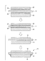
- a flux component intrusion prevention layer 51 is formed on the periphery of the joint surface between the ceramic substrate 11 and the metal layer 13 in the power module substrate 10. As shown in FIG. 1, the flux component intrusion prevention layer 51 has a fillet shape. That is, the flux component intrusion prevention layer 51 is formed over almost the entire lower surface of the peripheral portion excluding the joint surface with the metal layer 13 of the ceramic substrate 11 and almost the entire side surface of the metal layer 13. The peripheral edge portion of the joint surface between the ceramic substrate 11 and the metal layer 13 is completely covered by 51.
- the flux component intrusion prevention layer 51 contains an oxide and a resin. More specifically, the content of the oxide is 5% by volume or more and 60% by volume or less, and the remainder is a resin.
- the oxide one or more of TiO 2 , SiO 2 , and Al 2 O 3 are used.
- the particle size of the oxide is preferably in the range of 0.01 ⁇ m to 20 ⁇ m. More preferably, it is 0.1 ⁇ m or more and 20 ⁇ m or less.
- a heat sink 40 material to be joined
- TiO 2 is suitably used as an oxide that decomposes KAlF 4 that is a flux component. More specifically, it preferably contains TiO 2 in the range of 60 vol% 5 vol% or more or less.
- acrylic resin acrylic resin, cellulose resin, butyral resin, or the like can be used.
- acrylic resin is particularly preferably used.
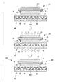
- the power module 1 includes a power module substrate 30 with a heat sink, and a semiconductor chip 3 bonded to the surface of the circuit layer 12 via a solder layer 2.
- the power module substrate 30 with a heat sink is obtained by bonding a heat sink 40 to the power module substrate 10 described above.
- the heat sink 40 and the power module substrate 10 are joined by noclock brazing using a flux mainly composed of KAlF 4 .
- the heat sink 40 is for cooling the power module substrate 10 described above.
- the heat sink 40 according to the present embodiment includes a top plate portion 41 joined to the power module substrate 10, a bottom plate portion 45 disposed so as to face the top plate portion 41, and the top plate portion 41 and the bottom plate portion 45.
- a corrugated fin 46 interposed between the top plate portion 41, the bottom plate portion 45, and the corrugated fin 46 defines a flow path 42 through which a cooling medium flows.
- the resin in the flux component intrusion prevention layer 51 of the power module substrate 10 is thermally decomposed and removed. Therefore, the flux component intrusion prevention layer 51 in the power module substrate 30 with a heat sink shown in FIG. 2 contains almost no resin component and is made of an oxide (for example, TiO 2 in this embodiment).
- the flux component intrusion prevention layer forming paste 50 contains the above-described oxide, the above-described resin, and a solvent. More specifically, the content of the oxide is based on the mass of the paste. 10 mass% or more and 80 mass% or less, resin content is 5 mass% or more and 30 mass% or less, and the remainder is made into the solvent.
- TiO 2 that decomposes KAlF 4 that is a flux component is preferably used as the oxide.
- TiO 2 is contained in an amount of 10% by mass to 80% by mass. It is preferable to contain within the following ranges.
- nonpolar solvents such as cyclohexane, methylcyclohexane, ethylcyclohexane, dibutyl ether and the like are suitable, and one or more of these are used in combination.
- the resin is preferably dissolved in a solvent.
- the flux component intrusion prevention layer forming paste 50 has a viscosity at a shear rate of 10 s ⁇ 1 at a temperature of 25 ° C. within the range of 10 mPa ⁇ s to 20000 mPa ⁇ s, and the shear at a temperature of 25 ° C.
- the viscosity at a speed of 100 s ⁇ 1 is in the range of 10 mPa ⁇ s to 5000 mPa ⁇ s. More preferably, the viscosity at a shear rate of 10 s ⁇ 1 at a temperature of 25 ° C.
- the viscosity at a shear rate of 100 s ⁇ 1 at a temperature of 25 ° C. is 50 mPa ⁇ s or more. It is within the range of 2500 mPa ⁇ s or less.
- the viscosity at a predetermined shear rate is obtained by applying a predetermined shear rate to the flux component intrusion prevention layer forming paste 50 using a cone (4 °, diameter 40 mm) as a measuring jig in a stress meter and rotating the cone.
- the viscosity value after 3 minutes shall be shown.
- the flux component intrusion prevention layer forming paste 50 may contain a dispersant as required.
- the resin content may be reduced by the content of the dispersant.
- the dispersant include anionic, cationic and nonionic surfactants.
- a preferable content of the dispersant is not limited, but is, for example, 0.01 to 5% by mass based on the total amount of the paste. Within this range, a dispersion effect can be obtained, and the influence of residual dispersant is less likely to occur.
- a metal plate 22 (4N aluminum rolled plate) to be the circuit layer 12 is a brazing material foil having a thickness of 5 to 50 ⁇ m (14 ⁇ m in this embodiment). 24 are stacked.
- a metal plate 23 (4N aluminum rolled plate) serving as the metal layer 13 is laminated via a brazing filler metal foil 25 having a thickness of 5 to 50 ⁇ m (14 ⁇ m in this embodiment).
- the brazing material foils 24 and 25 for example, an Al—Si based brazing material containing Si which is a melting point lowering element is used.
- the metal plate 22, the ceramic substrate 11, and the metal plate 23 are charged in the stacking direction (pressure 1 to 5 kgf / cm 2 ) in a heating furnace and heated. Then, the brazing material foils 24 and 25 and a part of the metal plates 22 and 23 are melted, and molten metal regions are formed at the interfaces between the metal plates 22 and 23 and the ceramic substrate 11, respectively.
- the heating temperature is, for example, 550 ° C. or more and 650 ° C. or less, and the heating time is 30 minutes or more and 180 minutes or less.
- the ceramic substrate 11, the metal plate 22, and the metal plate 23 are joined by solidifying the molten metal regions formed at the interfaces between the metal plates 22 and 23 and the ceramic substrate 11, respectively.
- a flux component intrusion prevention layer 51 is formed on the periphery of the joint surface between the ceramic substrate 11 and the metal layer 13 (metal plate 23).
- a method for forming the flux component intrusion prevention layer 51 will be described with reference to FIG. First, the paste 50 for flux component penetration
- the applied flux component intrusion prevention layer paste 50 is allowed to stand. Then, the flux component intrusion prevention layer paste 50 sags moderately by its own weight, and a fillet shape is formed as shown in FIG. 6 (fillet shape forming step S22). Next, the paste is dried under conditions of 50 to 150 ° C. ⁇ 3 to 30 minutes (drying step S23). At this time, the solvent in the flux component intrusion prevention layer forming paste 50 is removed, and the flux component intrusion prevention layer 51 made of an oxide (for example, TiO 2 in the present embodiment) and a resin (for example, an acrylic resin in the present embodiment). Is formed.
- an oxide for example, TiO 2 in the present embodiment
- a resin for example, an acrylic resin in the present embodiment
- a heat sink 40 is bonded to the other surface side of the metal layer 13 of the power module substrate 10.
- an Al—Si based brazing material foil 27 and a flux (not shown) mainly composed of KAlF 4 are interposed. .
- the laminated power module substrate 10 and the heat sink 40 are pressurized in the laminating direction (pressure 0 to 10 kgf / cm 2 ), they are placed in an atmosphere heating furnace and heated, and the metal layer 13 and the heat sink are heated. A molten metal region is formed between the 40 top plates 41.
- the inside of the atmosphere heating furnace is an inert gas atmosphere such as nitrogen gas, and the heating temperature is set in a range of 550 ° C. or more and 630 ° C. or less.
- the metal layer 13 of the power module substrate 10 and the top plate portion 41 of the heat sink 40 are joined. At this time, oxide films are formed on the surfaces of the metal layer 13 and the top plate portion 41, but these oxide films are removed by the aforementioned flux. Further, the flux component is liquefied and vaporized, and moves to the ceramic substrate 11 side. In this way, the heat sink 40 and the power module substrate 10 are joined together to manufacture the power module substrate 30 with a heat sink.
- the flux component intrusion prevention layer 51 containing an oxide and a resin is formed on the periphery of the joint surface between the ceramic substrate 11 and the metal layer 13. since it is, the other surface of the metal layer 13, in joining the heatsink 40 by using the flux, even KAlF 4 is a flux component has moved to the ceramic substrate 11 side, KAlF 4 flux component intrusion prevention layer Since it is decomposed in contact with the oxide in 51, it is possible to prevent KAlF 4 that is a flux component from entering the bonding surface between the ceramic substrate 11 and the metal layer 13.
- the composition of the flux component intrusion prevention layer 51 includes an oxide in the range of 5 volume% or more and 60 volume% or less, and the remainder is made of resin. Therefore, the flux component can be reliably decomposed, and the ceramic substrate 11 It is possible to reliably suppress the flux component from entering the joint surface between the metal layer 13 and the metal layer 13. Since the oxide content is set to 60% by volume or less, the resin content in the flux component intrusion prevention layer 51 is ensured, and the heat sink joint for joining the heat sink 40 by the adhesive force of the resin component. It is possible to prevent the flux component intrusion prevention layer 51 from dropping from the power module substrate 10 by Step S13.
- the flux component intrusion prevention layer 51 since the flux component intrusion prevention layer 51 has a fillet shape, the flux component intrusion prevention layer 51 is formed so as to extend to the other surface of the ceramic substrate 11 and the side surface of the metal layer 13, respectively. In addition, it is possible to reliably suppress the flux component from entering the joint surface between the ceramic substrate 11 and the metal layer 13.
- the oxide contained in the flux component intrusion prevention layer 51 is one or more of TiO 2 , SiO 2 , and Al 2 O 3. In this embodiment, the oxide contains TiO 2 . Therefore, it is possible to reliably decompose the flux mainly composed of KAlF 4 that is used in Nocolok brazing.
- An acrylic resin is used as the resin contained in the flux component intrusion prevention layer 51. The acrylic resin undergoes depolymerization when heated, has good thermal decomposition characteristics even under an inert gas atmosphere, and can be suppressed from remaining in the flux component intrusion prevention layer 51 after firing.
- the power module substrate 30 with a heat sink since the aforementioned flux component intrusion prevention layer 51 is formed at the periphery of the bonding surface between the ceramic substrate 11 and the metal layer 13, when the heat sink 40 is bonded, KAlF 4 which is a flux component is prevented from entering the bonding surface between the ceramic substrate 11 and the metal layer 13. Therefore, it is possible to provide the power module substrate 30 with a heat sink excellent in the bonding reliability between the ceramic substrate 11 and the metal layer 13.
- the flux component intrusion prevention layer paste 50 since contains decomposing oxide flux ingredients, when KAlF 4 is in contact with the flux component intrusion prevention layer 51, will be KAlF 4 is decomposed
- the flux component KAlF 4 can be prevented from entering the bonding surface between the ceramic substrate 11 and the metal layer 13.
- a suitable TiO 2 flux mainly composed of KAlF 4 as decomposing oxides when the KAlF 4 is in contact with the flux component intrusion prevention layer 51, capable of degrading KAlF 4 efficiently .
- the flux component intrusion prevention layer paste 50 has a viscosity at a shear rate of 10 s ⁇ 1 at a temperature of 25 ° C. within a range of 10 mPa ⁇ s to 20000 mPa ⁇ s, and a viscosity at a temperature of 25 ° C. at a shear rate of 100 s ⁇ 1 . Is applied within the range of 10 mPa ⁇ s or more and 5000 mPa ⁇ s or less. Therefore, the flux component intrusion prevention layer forming paste 50 is formed around the joint surface between the ceramic substrate 11 and the metal layer 13. Can be applied satisfactorily.
- the viscosity at a shear rate of 10 s ⁇ 1 at a temperature of 25 ° C. is in the range of 10 mPa ⁇ s to 10000 mPa ⁇ s
- the viscosity at a shear rate of 100 s ⁇ 1 at a temperature of 25 ° C. is from 50 mPa ⁇ s to 2500 mPa ⁇ s.
- oxide powder TiO 2 powder
- a nonpolar solvent such as cyclohexane, methylcyclohexane, ethylcyclohexane, or dibutyl ether
- the content of the oxide (TiO 2 ) is 10% by mass or more and 80% by mass or less, the content of the resin is 5% by mass or more and 30% by mass or less, and the remainder is Since it is a solvent, the flux component can be reliably decomposed and rendered harmless, and the fillet shape formed by coating can be maintained, and the flux component intrusion prevention layer 51 can be reliably formed. Is possible.
- the joint surface between the ceramic substrate 11 and the metal layer 13 of the power module substrate 10 can suppress the KAlF 4 is a flux component enters, joining The power module substrate 10 and the heat sink 40 can be satisfactorily bonded without reducing the bonding reliability on the surface.
- the circuit layer is not limited to this, and the circuit layer may be composed of an aluminum alloy plate, a copper plate, or a copper alloy plate.
- the circuit layer may be composed of an aluminum alloy plate, a copper plate, or a copper alloy plate.
- a ceramic substrate made of AlN it is not limited thereto, and may be another ceramic substrate such as Al 2 O 3, Si 3 N 4, using another insulating material It may be.
- the bonding method of the ceramic substrate, the circuit layer, and the metal layer is not limited to this embodiment, and may be bonded by other methods.
- the flux component intrusion prevention layer 151 is formed on the periphery of the joint surface between the ceramic substrate 111 and the metal layer 113, but also the circuit layer 112 and the ceramic substrate 111.
- the flux component intrusion prevention layer 152 may also be formed on the periphery of the bonding surface.
- the flux component is vaporized, there is a risk of entering the bonding surface between the circuit layer 112 and the ceramic substrate 111 beyond the ceramic substrate 111. Therefore, the peripheral edge of the bonding surface between the circuit layer 112 and the ceramic substrate 111 In addition, it is preferable to form the flux component penetration preventing layer 152.
- the raw material and blending amount of the flux component intrusion prevention layer paste are not limited to those described in the embodiment, and other oxides, resins, and solvents may be used.
- the oxide that decomposes the flux is not limited to TiO 2 , and may be any one or a mixture of two or more of TiO 2 , SiO 2 , and Al 2 O 3 . It may be an oxide. About the kind of this oxide, it is preferable to select according to the flux used for joining.
- the description has been made using the acrylic resin as the resin the present invention is not limited to this, and other resins may be used.
- a nonpolar solvent such as cyclohexane, methylcyclohexane, ethylcyclohexane, and dibutyl ether as a solvent
- the present invention is not limited to this, and other solvents may be used.
- a power module substrate formed by joining a ceramic substrate and a metal plate and a heat sink (joined material) are joined using a flux whose main component is KAlF 4.
- a joined body having a first member and a second member joined via a joining surface and a material to be joined are joined using a flux. Can be applied to things.
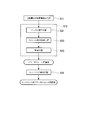
- the flux component intrusion prevention layer paste having the composition shown in Table 1 was manufactured by the procedure described in the flow chart of FIG. In Comparative Example A2, the flux component intrusion prevention layer paste was not used.
- the organic substance mixing step S1 stirring was performed for 30 minutes using a planetary stirrer (“AR-250” (trade name) manufactured by Sinky Corporation) to dissolve the resin in a solvent.
- the kneading step S2 stirring was performed for 30 minutes using a planetary stirrer (“AR-250” (trade name) manufactured by Sinky Corporation).
- a flux component intrusion preventing layer was formed on the power module substrate disclosed in the above embodiment.
- the flux component intrusion prevention layer was not formed.
- the ceramic substrate used in each example and each comparative example was 30 mm ⁇ 20 mm ⁇ 0.635 mm
- the circuit layer was 13 mm ⁇ 10 mm ⁇ 0.6 mm
- the metal layer was 13 mm ⁇ 10 mm ⁇ 1.6 mm.
- the top plate of the heat sink was 50 mm ⁇ 50 mm ⁇ 7 mm.
- a drop test of the flux component intrusion prevention layer was performed.
- the power module substrate on which the flux component intrusion prevention layer was formed was placed on a plastic tray and shaken with a shaker at 300 rpm for 3 hours to observe whether the flux component intrusion prevention layer was removed.
- the case where omission was not recognized was evaluated as ⁇
- the case where a piece of 0.5 mm or less was found to be slightly removed was evaluated as ⁇
- the case where a piece of 0.5 mm or more was observed as dropped was evaluated as x. If a piece of 0.5 mm or less is slightly removed, it is at a level that does not cause a problem in practice.
- the bonding surface between the ceramic substrate and the metal layer was observed with an ultrasonic flaw detector (“Fine SAT FS-200” (trade name) manufactured by Hitachi Engineering & Service Co., Ltd.). The bonding reliability was evaluated. Peeling at the time of noco-lock joining occurs from the outer periphery of the metal layer, and in the ultrasonic flaw detection image, this peeling part is shown as a white part in the joined part, so the length of the white part along the outer part of the metal layer is measured. The peel length was used.
- peel length ratio The case where no peeling occurred was evaluated as ⁇ , the case where the ratio of the peeling length to the length of one side of the joint surface (peeling length rate) was 30% or less, and the case where the peeling length rate exceeded 30% were evaluated as x. If the peel length ratio was 30% or less, it was evaluated that there was actually no problem.
- peel length ratio The evaluation results and peel length ratio are shown in Table 2.
- Comparative Example A1 in which the flux component intrusion prevention layer containing no oxide was formed, the evaluation of the dropout test was good, but it was confirmed that the bonding reliability was poor. This is presumed that since the flux component intrusion prevention layer does not have an oxide, the flux component cannot be decomposed, and the flux component penetrates into the joint surface between the ceramic substrate and the metal layer, thereby lowering the joining reliability. . In Comparative Example A2 in which the flux component intrusion prevention layer forming paste was not formed, it was confirmed that the bonding reliability was inferior. This is presumed that the flux component entered the bonding surface between the ceramic substrate and the metal layer, and the bonding reliability was lowered.
- Example A6 in which the content of oxide in the flux component intrusion prevention layer (the amount of oxide after drying) was 70.1%, the content of the resin was small, so the flux component intrusion prevention layer was used in the dropout test. A dropout was observed in part of In Example A7 in which the content of oxide in the flux component intrusion prevention layer (the amount of oxide after drying) was 4.5%, the content of oxide was small, so compared with Examples A1-A6, A slight decrease in bonding reliability was observed.
- the present invention it is possible to prevent a decrease in the bonding reliability between the ceramic substrate and the metal layer when the heat sink is bonded. Furthermore, by making the content of the oxide in the flux component intrusion prevention layer desirably in the range of 5% by volume or more and 60% by volume or less, the flux component intrusion prevention layer can be prevented from falling off and more reliably bonded reliability. It was confirmed that the decrease in the thickness could be prevented.
- the flux component intrusion prevention layer paste having the composition shown in Table 3 was manufactured by the procedure described in the flow chart of FIG.
- the organic substance mixing step S01 stirring was performed for 30 minutes using a planetary stirrer (“AR-250” (trade name) manufactured by Sinky Corporation) to dissolve the resin in the solvent.
- a planetary stirrer (“AR-250” (trade name) manufactured by Sinky Corporation) to dissolve the resin in the solvent.
- the kneading step S02 stirring was performed for 5 minutes using a planetary stirring device (“AR-250” (trade name) manufactured by Shinky Corporation).
- the obtained flux component intrusion prevention layer paste was measured for a viscosity at a shear rate of 10 s ⁇ 1 at a temperature of 25 ° C. and a viscosity at a shear rate of 100 s ⁇ 1 at a temperature of 25 ° C.
- a stress rheometer (“AR-1000" (trade name) manufactured by TA Instruments Co., Ltd.) was used with a cone (4 °, 40 mm in diameter) as a measuring jig, and this cone was rotated to paste the flux component intrusion prevention layer paste.
- AR-1000 (trade name) manufactured by TA Instruments Co., Ltd.) was used with a cone (4 °, 40 mm in diameter) as a measuring jig, and this cone was rotated to paste the flux component intrusion prevention layer paste.
- Table 4 shows the measurement results.
- the flux component intrusion prevention layer of the power module substrate disclosed in the above embodiment was formed.
- the ceramic substrate is 30 mm x 20 mm x 0.635 mm
- the circuit layer is 13 mm x 10 mm x 0.6 mm
- the metal layer is 13 mm x 10 mm x 1.6 mm
- the top plate of the heat sink is 50 mm x 50 mm x 7 mm Met.
- a flux component intrusion prevention layer paste was applied to the periphery of the joint surface. After the application, a drying treatment was performed on a hot plate at 80 ° C. for 5 minutes.
- the fillet shape was evaluated.
- the flux component intrusion prevention layer was observed with an optical microscope, and the presence or absence of the flux component intrusion prevention layer paste was confirmed. ⁇ if no omission or gap is confirmed, ⁇ if omission of 3 mm or less or gap is confirmed only in one place, ⁇ if omission or gap more than 3 mm in length is confirmed, or length is 3 mm
- the case where two or more of the following gaps or gaps were confirmed was evaluated as x. When there is a gap or gap of 3 mm or less in length, there is no practical problem.
- the bonding surface between the ceramic substrate and the metal layer is observed with an ultrasonic flaw detector (“Fine SAT FS-200” (trade name) manufactured by Hitachi Engineering & Service Co., Ltd.). Reliability was evaluated. Peeling at the time of noco-lock joining occurs from the outer periphery of the metal layer, and in the ultrasonic flaw detection image, this peeling part is shown as a white part in the joined part, so the length of the white part along the outer part of the metal layer is measured. The peel length was used. The case where there was no peeling was evaluated as ⁇ , the case where the ratio of the peeling length to the length (peeling length ratio) was 30% or less, ⁇ , and the case where the peeling length ratio exceeded 30% was evaluated as x. Table 4 shows the evaluation results and the peel length ratio.
- the viscosity at a shear rate of 10 s ⁇ 1 at a temperature of 25 ° C. is in the range of 10 mPa ⁇ s to 20000 mPa ⁇ s, and the viscosity at a shear rate of 100 s ⁇ 1 at a temperature of 25 ° C. is from 10 mPa ⁇ s to 5000 mPa ⁇ s.
- the initial bonding reliability and the bonding reliability after the thermal cycle were confirmed to be good. This is presumably because the flux component did not enter the bonding surface between the ceramic substrate and the metal layer. Further, the viscosity at a shear rate of 10 s ⁇ 1 at a temperature of 25 ° C.
- Comparative Examples B1-B3 it was confirmed that the bonding reliability was low.
- the viscosity at a shear rate of 10 s ⁇ 1 at a temperature of 25 ° C. is in the range of 10 mPa ⁇ s to 10,000 mPa ⁇ s, and the shear rate at a temperature of 25 ° C. is 100 s ⁇ . Since the viscosity at 1 is in the range of 50 mPa ⁇ s to 2500 mPa ⁇ s, the coating shape is good. However, since the oxide does not have an oxide that decomposes the flux component, the flux component cannot be decomposed, and the flux component enters the bonding surface between the ceramic substrate and the metal layer, and it is assumed that the bonding reliability is lowered.
- Comparative Example B2 in which the viscosity at a shear rate of 10 s ⁇ 1 at a temperature of 25 ° C. was 28000 mPa ⁇ s, the applied shape was poor because the paste after application did not sag. Thereby, it is presumed that the flux component entered the bonding surface between the ceramic substrate and the metal layer, and the bonding reliability was lowered.
- Comparative Example B3 in which the viscosity at a shear rate of 100 s ⁇ 1 at a temperature of 25 ° C. was 8000 mPa ⁇ s, the paste could not be applied satisfactorily and the fillet shape was poor. Thereby, it is presumed that the flux component entered the bonding surface between the ceramic substrate and the metal layer, and the bonding reliability was lowered.
- the flux intrusion prevention layer can be reliably adhered, and the bonding reliability between the insulating layer and the metal plate is lowered. Since this can be suppressed, industrial use is possible.
Abstract
Provided is a power module substrate (10) in which a circuit layer (12) is formed on one surface of an insulating layer (11), a metal layer (13) is formed on another surface of the insulating layer (11), and flux is used on another surface of the metal layer (13) to bond an article to be bonded. Flux component penetration prevention layers (51) are formed on peripheral edge sections of a surface at which the insulating layer (11) and the metal layer (13) are bonded.
Description
この発明は、絶縁層の一方の面に回路層が形成され、前記絶縁層の他方の面に金属層が形成されており、この金属層の他方の面にフラックスを使用して被接合体が接合されるパワーモジュール用基板、このパワーモジュール用基板を備えたヒートシンク付パワーモジュール用基板、パワーモジュール、フラックス成分が接合面に侵入することを抑制するためのフラックス成分侵入防止層を形成する際に使用されるフラックス成分侵入防止層形成用ペースト、及び、このフラックス成分侵入防止層形成用ペーストを使用した接合体の接合方法に関する。
本願は、2011年12月12日に日本で出願された特願2011-271081号、および2011年12月12日に日本で出願された特願2011-271146号に基づき優先権を主張し、それらの内容をここに援用する。 In the present invention, a circuit layer is formed on one surface of an insulating layer, and a metal layer is formed on the other surface of the insulating layer. When forming a power module substrate to be bonded, a power module substrate with a heat sink equipped with the power module substrate, a power module, and a flux component intrusion prevention layer for suppressing flux components from entering the bonding surface The present invention relates to a flux component intrusion prevention layer forming paste used and a joining method of a joined body using the flux component intrusion prevention layer forming paste.
This application claims priority based on Japanese Patent Application No. 2011-271081 filed in Japan on December 12, 2011 and Japanese Patent Application No. 2011-271146 filed in Japan on December 12, 2011. Is incorporated herein by reference.
上述のパワーモジュール用基板及びヒートシンク付パワーモジュール用基板としては、例えば特許文献1に記載されているように、AlN(窒化アルミニウム)からなるセラミックス基板の両面にAl(アルミニウム)の金属板(回路層及び金属層)が接合されたパワーモジュール用基板と、アルミニウムからなるヒートシンクとが、ろう付けによって接合されたものが提案されている。
特許文献2には、セラミックス材からなる絶縁基板の両面にAl(アルミニウム)の金属板(上部電極及び下部電極)が接合されており、上部電極に半導体素子が接合された半導体モジュールと、アルミニウムからなる冷却器の天板とが、フラックスを用いたろう付けによって接合された半導体モジュールの冷却装置が提案されている。 As the above-mentioned power module substrate and power module substrate with heat sink, for example, as described inPatent Document 1, Al (aluminum) metal plates (circuit layers) on both sides of a ceramic substrate made of AlN (aluminum nitride). And a power module substrate to which a metal layer is bonded and a heat sink made of aluminum are bonded by brazing.
InPatent Document 2, Al (aluminum) metal plates (upper electrode and lower electrode) are bonded to both surfaces of an insulating substrate made of a ceramic material, and a semiconductor module in which a semiconductor element is bonded to the upper electrode; There has been proposed a cooling device for a semiconductor module in which a top plate of a cooler is joined by brazing using a flux.
特許文献2には、セラミックス材からなる絶縁基板の両面にAl(アルミニウム)の金属板(上部電極及び下部電極)が接合されており、上部電極に半導体素子が接合された半導体モジュールと、アルミニウムからなる冷却器の天板とが、フラックスを用いたろう付けによって接合された半導体モジュールの冷却装置が提案されている。 As the above-mentioned power module substrate and power module substrate with heat sink, for example, as described in
In
特許文献3には、パワーモジュールにおける絶縁積層材のろう付け方法が開示されている。この方法では、ボロンナイトライドまたはカーボンの粉末を有機化合物からなる分散媒に分散させて懸濁液をつくり、この懸濁液を、アルミニウム製の伝熱層の周面に塗布することによって、フラックス浸入防止物を伝熱層の周面に付着させる。この状態で、前記伝熱層と応力緩和部材とをフラックスを使用してろう付することにより、溶融したフラックスが、金属層の周面に沿って絶縁板と金属層の界面に侵入することを防止する。
Patent Document 3 discloses a method for brazing an insulating laminated material in a power module. In this method, boron nitride or carbon powder is dispersed in a dispersion medium made of an organic compound to form a suspension, and this suspension is applied to the peripheral surface of an aluminum heat transfer layer, thereby producing a flux. Adhere intrusion prevention material to the peripheral surface of the heat transfer layer. In this state, the heat transfer layer and the stress relaxation member are brazed using a flux, so that the melted flux penetrates the interface between the insulating plate and the metal layer along the peripheral surface of the metal layer. To prevent.
フラックスを用いたろう付けとしては、例えば特許文献4、5に記載されているように、KAlF4を主成分とするフラックスを用いたノコロックろう付けが知られている。
このノコロックろう付けは、主に、アルミニウム部材同士を接合する技術であり、例えばAl-Si系ろう材箔とKAlF4を主成分とするフラックスとを、アルミニウム部材同士の間に配置し、フラックスによってアルミニウム部材の表面に形成された酸化膜を除去するとともに、ろう材の溶融を促進して、接合する。 As brazing using a flux, as described in Patent Documents 4 and 5, for example, nocollock brazing using a flux mainly composed of KAlF 4 is known.
This Nocolok brazing is mainly a technique for joining aluminum members together. For example, an Al—Si brazing foil and a flux mainly composed of KAlF 4 are disposed between aluminum members, The oxide film formed on the surface of the aluminum member is removed and the melting of the brazing material is promoted to join.
ところで、パワーモジュール用基板とヒートシンクをノコロックろう付けで接合する場合には、フラックス成分であるKAlF4がパワーモジュール用基板のセラミックス板と金属板との接合面に侵入し、セラミックス板と金属板との間の接合信頼性が低下するおそれがあった。
By the way, when the power module substrate and the heat sink are joined by Nocolok brazing, KAlF 4 which is a flux component enters the joining surface between the ceramic plate and the metal plate of the power module substrate, and the ceramic plate and the metal plate There was a risk that the bonding reliability between the two would decrease.
特に、ヒートシンク付パワーモジュール基板においては、セラミックス基板と金属板との接合面と、パワーモジュール用基板とヒートシンクとの界面との間が金属層のみで隔てられ、両者が近接していることから、フラックス成分がパワーモジュール用基板のセラミックス板と金属板との接合面に侵入しやすい傾向にある。
さらに、フラックス成分がセラミックス基板を超えて回路層にまで達する場合には、回路層と金属層との絶縁性が低下してしまい、パワーモジュール用基板として使用できなくなるおそれがあった。
そのため、特許文献2では、セラミックス板と金属板との接合端部にホウ素や酸化チタン等で構成された接触防止材(フラックス侵入防止層)を塗布することが提案されている。 In particular, in the power module substrate with a heat sink, the bonding surface between the ceramic substrate and the metal plate and the interface between the power module substrate and the heat sink are separated by only the metal layer, and both are close to each other. The flux component tends to easily enter the joint surface between the ceramic plate and the metal plate of the power module substrate.
Furthermore, when the flux component reaches the circuit layer beyond the ceramic substrate, the insulation between the circuit layer and the metal layer is lowered, and there is a possibility that it cannot be used as a power module substrate.
Therefore, inPatent Document 2, it is proposed to apply a contact prevention material (flux intrusion prevention layer) made of boron, titanium oxide, or the like to the joint end portion between the ceramic plate and the metal plate.
さらに、フラックス成分がセラミックス基板を超えて回路層にまで達する場合には、回路層と金属層との絶縁性が低下してしまい、パワーモジュール用基板として使用できなくなるおそれがあった。
そのため、特許文献2では、セラミックス板と金属板との接合端部にホウ素や酸化チタン等で構成された接触防止材(フラックス侵入防止層)を塗布することが提案されている。 In particular, in the power module substrate with a heat sink, the bonding surface between the ceramic substrate and the metal plate and the interface between the power module substrate and the heat sink are separated by only the metal layer, and both are close to each other. The flux component tends to easily enter the joint surface between the ceramic plate and the metal plate of the power module substrate.
Furthermore, when the flux component reaches the circuit layer beyond the ceramic substrate, the insulation between the circuit layer and the metal layer is lowered, and there is a possibility that it cannot be used as a power module substrate.
Therefore, in
しかし、このフラックス侵入防止層はパワーモジュール用基板とヒートシンクとの接合前に予め塗布する必要があるが、パワーモジュール用基板とヒートシンクとの接合工程に至るまでには、工場間の輸送、工場内の搬送、接合冶具へのセッティングなどの工程を経る必要があり、そのような工程を経てもフラックス侵入防止層を確実に付着させておく必要がある。
However, it is necessary to apply this flux intrusion prevention layer in advance before joining the power module substrate and the heat sink. It is necessary to go through steps such as transporting and setting to a joining jig, and it is necessary to securely attach the flux intrusion prevention layer even after going through such steps.
この発明の第1の態様は、絶縁層と金属層との接合面の周縁部にフラックス侵入防止層を確実に付着させておくことができ、フラックスを用いて被接合材を接合した場合であっても、絶縁層と金属層との接合信頼性が低下することを抑制できるパワーモジュール用基板、ヒートシンク付パワーモジュール用基板及びパワーモジュールを提供することを課題とする。
The first aspect of the present invention is a case where the flux intrusion prevention layer can be reliably adhered to the peripheral edge portion of the joining surface between the insulating layer and the metal layer, and the materials to be joined are joined using the flux. However, it is an object of the present invention to provide a power module substrate, a power module substrate with a heat sink, and a power module that can suppress a decrease in the bonding reliability between the insulating layer and the metal layer.
この発明の他の態様は、フラックス成分侵入防止層を確実に形成でき、接合体と被接合体とを良好に接合することが可能なフラックス成分侵入防止層形成用ペーストおよび接合体の接合方法を提供することを課題とする。
According to another aspect of the present invention, there is provided a flux component intrusion prevention layer forming paste capable of reliably forming a flux component intrusion prevention layer and capable of satisfactorily joining the joined body and the joined body, and a joining method of the joined body. The issue is to provide.
本発明の第1の態様のパワーモジュール用基板は、絶縁層の一方の面に回路層が形成され、前記絶縁層の他方の面に金属層が形成されており、この金属層の他方の面にフラックスを使用して被接合体が接合されるパワーモジュール用基板であって、前記絶縁層と前記金属層との接合面の周縁部には、酸化物と樹脂とを含有するフラックス成分侵入防止層が形成されている。
In the power module substrate according to the first aspect of the present invention, a circuit layer is formed on one surface of an insulating layer, and a metal layer is formed on the other surface of the insulating layer, and the other surface of the metal layer. A substrate for a power module to which an object to be bonded is bonded using a flux, and preventing the penetration of a flux component containing an oxide and a resin at the periphery of the bonding surface between the insulating layer and the metal layer A layer is formed.
この構成のパワーモジュール用基板によれば、前記絶縁層と前記金属層との接合面の周縁部に、酸化物と樹脂とを含有するフラックス成分侵入防止層が形成されているので、金属層の他方の面にフラックスを使用して被接合体を接合する際に、フラックス成分が前記絶縁層側に移動してきても、フラックス成分が前記酸化物に接触して分解されるため、前記絶縁層と前記金属層との接合面にフラックス成分が進入することを抑制できる。これは、フラックス成分侵入防止層に含まれる酸化物とフラックス成分が反応することにより、フラックス成分が分解し、フラックスとしての活性を失うことによるものと考えられる。
また、フラックス成分侵入防止層が樹脂を含有しているので、輸送、搬送またはセッティング等で振動が生じたとしても、フラックス成分侵入防止層を、前記絶縁層と前記金属層との接合面の周縁部に形状を保持したまま確実に付着させておくことができる。
被接合体を接合した際には、その熱によってフラックス成分侵入防止層内の樹脂が分解されるから、被接合体を接合後のパワーモジュール用基板におけるフラックス成分侵入防止層は、ほとんどが酸化物で構成される。 According to the power module substrate having this configuration, the flux component intrusion prevention layer containing the oxide and the resin is formed at the peripheral edge portion of the joint surface between the insulating layer and the metal layer. When the object to be joined is bonded to the other surface using the flux, even if the flux component moves toward the insulating layer, the flux component is decomposed in contact with the oxide. The flux component can be prevented from entering the joint surface with the metal layer. This is considered to be due to the fact that the flux component is decomposed by the reaction between the oxide contained in the flux component intrusion prevention layer and the flux component, and the activity as the flux is lost.
In addition, since the flux component intrusion prevention layer contains a resin, the flux component intrusion prevention layer is formed at the periphery of the joint surface between the insulating layer and the metal layer even if vibration occurs during transportation, transportation, or setting. It is possible to securely attach the part while maintaining the shape.
Since the resin in the flux component intrusion prevention layer is decomposed by the heat when the object is joined, the flux component intrusion prevention layer in the power module substrate after joining the object to be joined is mostly an oxide. Consists of.
前記フラックス成分侵入防止層の組成は、前記酸化物を5体積%以上60体積%以下の範囲内で含み、残部が前記樹脂とされていることが好ましい。
この場合、酸化物の含有量が5体積%以上とされているので、ろう付けを行う際に前記フラックス成分侵入防止層に接触したフラックス成分を確実に分解することができ、前記絶縁層と前記金属層との接合面にフラックス成分が進入することを確実に抑制できる。酸化物の含有量が60体積%以下とされているので、フラックス成分侵入防止層内の樹脂の含有量が確保され、樹脂により付着力を高めてフラックス成分侵入防止層が脱落することを防止できる。 The composition of the flux component intrusion prevention layer preferably includes the oxide in a range of 5% by volume to 60% by volume, with the remainder being the resin.
In this case, since the content of the oxide is 5% by volume or more, the flux component in contact with the flux component intrusion prevention layer can be reliably decomposed when brazing, and the insulating layer and the It is possible to reliably suppress the flux component from entering the joint surface with the metal layer. Since the oxide content is 60% by volume or less, the content of the resin in the flux component intrusion prevention layer is ensured, and it is possible to prevent the flux component intrusion prevention layer from falling off by increasing the adhesive force by the resin. .
前記フラックス成分侵入防止層は、フィレット形状をなしていることが好ましい。フィレット形状とは、2つの交差する面を凹曲面で滑らかにつないだ裾広がりの形状をいう。
この場合、絶縁層の他方の面及び金属層の側面にそれぞれ延在するようにフラックス成分侵入防止層が形成されることになり、前記絶縁層と前記金属層との接合面にフラックス成分が進入することを確実に抑制できる。また、フラックス成分侵入防止層による被覆面積の大きさに比して、フラックス成分侵入防止層の体積をフラックス分解効果を得る上で必要充分な程度に小さくすることができる。 The flux component intrusion prevention layer preferably has a fillet shape. The fillet shape refers to a shape that spreads the hem and smoothly connects two intersecting surfaces with concave curved surfaces.
In this case, the flux component intrusion prevention layer is formed to extend to the other surface of the insulating layer and the side surface of the metal layer, respectively, and the flux component enters the joint surface between the insulating layer and the metal layer. Can be reliably suppressed. Further, the volume of the flux component intrusion prevention layer can be reduced to a level necessary and sufficient for obtaining the flux decomposition effect as compared with the size of the coating area by the flux component intrusion prevention layer.
前記酸化物は、TiO2、SiO2、Al2O3のうちのいずれか1種又は2種以上とされていることが好ましい。これら酸化物は、ろう付けの行われる温度範囲において、フラックス成分と反応することによりフラックス成分を酸化反応等により分解し、フラックスを失活することができる。特に、ノコロックろう付けで使用されるKAlF4を主成分とするフラックスを、確実に分解することが可能となる。
The oxide is preferably one or more of TiO 2 , SiO 2 , and Al 2 O 3 . These oxides can deactivate the flux by decomposing the flux component by oxidation reaction or the like by reacting with the flux component in the temperature range where brazing is performed. In particular, it is possible to reliably decompose the flux mainly composed of KAlF 4 used in Nocolok brazing.
前記樹脂としては、アクリル樹脂、セルロース樹脂、ブチラール樹脂等を用いることができ、特に、アクリル樹脂であることが好ましい。アクリル樹脂は、ろう付けの行われる温度範囲に加熱された時に解重合を起こすため、不活性ガス雰囲気下においても良好な熱分解特性を有することになり、焼成後のフラックス成分侵入防止層内に樹脂が残存することを抑制できる。
As the resin, acrylic resin, cellulose resin, butyral resin or the like can be used, and acrylic resin is particularly preferable. Since acrylic resin undergoes depolymerization when heated to the temperature range where brazing is performed, it will have good thermal decomposition characteristics even in an inert gas atmosphere, and in the flux component intrusion prevention layer after firing. Residual resin can be suppressed.
本発明の他の態様のヒートシンク付パワーモジュール用基板は、上述のパワーモジュール用基板と、前記パワーモジュール用基板の前記金属層にフラックスを用いて接合されたヒートシンクと、を備える。
この構成のヒートシンク付パワーモジュール用基板によれば、絶縁層と金属層との接合面の周縁に前述のフラックス成分侵入防止層が形成されているので、ヒートシンクを接合する際に、フラックス成分が絶縁層と金属層との接合面に侵入することが防止される。よって、絶縁層と金属層との接合信頼性に優れる。
ヒートシンクを接合した際には、その熱によってフラックス成分侵入防止層内の樹脂が分解されることから、ヒートシンク付パワーモジュール用基板におけるフラックス成分侵入防止層は、ほとんどが酸化物で構成される。 A power module substrate with a heat sink according to another aspect of the present invention includes the power module substrate described above and a heat sink bonded to the metal layer of the power module substrate using a flux.
According to the power module substrate with a heat sink having this configuration, the flux component intrusion prevention layer is formed on the periphery of the joint surface between the insulating layer and the metal layer. Therefore, when the heat sink is joined, the flux component is insulated. Intrusion into the joint surface between the layer and the metal layer is prevented. Therefore, the bonding reliability between the insulating layer and the metal layer is excellent.
Since the resin in the flux component intrusion prevention layer is decomposed by the heat when the heat sink is joined, the flux component intrusion prevention layer in the power module substrate with a heat sink is mostly composed of an oxide.
本発明の他の態様のパワーモジュールは、上述のパワーモジュール用基板と、前記回路層上に配設された電子部品とを備える。この構成のパワーモジュールによれば、絶縁層と金属層とが確実に接合されることになり、信頼性を大幅に向上させることができる。
A power module according to another aspect of the present invention includes the above-described power module substrate and an electronic component disposed on the circuit layer. According to the power module having this configuration, the insulating layer and the metal layer are reliably bonded, and the reliability can be greatly improved.
本発明の他の態様のフラックス成分侵入防止層形成用ペーストは、前記フラックス成分を分解する酸化物と、樹脂と、溶剤とを含有し、温度25℃でのずり速度10s-1における粘度が、10mPa・s以上20000mPa・s以下の範囲内とされ、温度25℃でのずり速度100s-1における粘度が、10mPa・s以上5000mPa・s以下の範囲内とされている。
The paste for forming a flux component intrusion prevention layer according to another aspect of the present invention contains an oxide that decomposes the flux component, a resin, and a solvent, and has a viscosity at a shear rate of 10 s −1 at a temperature of 25 ° C. The viscosity is in the range of 10 mPa · s to 20000 mPa · s, and the viscosity at a shear rate of 100 s −1 at a temperature of 25 ° C. is in the range of 10 mPa · s to 5000 mPa · s.
この構成のフラックス成分侵入防止層形成用ペーストによれば、前記フラックス成分を分解する酸化物を有しているので、フラックス成分と接触した際にフラックス成分を無害化することができ、第一部材と第二部材との接合面にフラックス成分が進入することを抑制できる。
According to the paste for forming a flux component intrusion prevention layer having this configuration, since it has an oxide that decomposes the flux component, the flux component can be rendered harmless when in contact with the flux component, and the first member The flux component can be prevented from entering the joint surface between the first member and the second member.
また、前記粘度条件を満たすことにより、第一部材と第二部材との接合面の周囲に対して、フラックス成分侵入防止層形成用ペーストを塗布することができ、かつ、塗布したフラックス成分侵入防止層形成用ペーストが適度にダレることによって良好なフィレット形状が形成され、フラックス成分侵入防止層を確実に形成することができる。
特に、絶縁層と金属層の接合面と、金属層とヒートシンクとの接合界面とが近接している場合には、フラックス成分侵入防止層を形成し難いが、本発明のフラックス成分侵入防止層形成用ペーストであれば、適度な粘度により塗布性および保持性に優れるので、フラックス成分侵入防止層を所望の塗布量および断面形状に形成することができる。 Further, by satisfying the viscosity condition, the flux component intrusion prevention layer forming paste can be applied to the periphery of the joint surface between the first member and the second member, and the applied flux component intrusion prevention can be performed. A good fillet shape is formed by moderately sagging the layer forming paste, and the flux component penetration preventing layer can be reliably formed.
In particular, when the bonding surface between the insulating layer and the metal layer and the bonding interface between the metal layer and the heat sink are close to each other, it is difficult to form the flux component penetration preventing layer. In the case of the paste for use, since the coating property and the holding property are excellent due to an appropriate viscosity, the flux component penetration preventing layer can be formed in a desired coating amount and a cross-sectional shape.
ずり速度10s-1における粘度が10mPa・s未満の場合には、ペーストを塗布した際のダレが大きくはみ出してペースト成分が接合体と被接合体との接合界面に入り込んでしまい、フラックスを用いた接合時の接合を阻害してしまうおそれがある。また、ずり速度10s-1における粘度が20000mPa・sを超えている場合には、ペーストを塗布した後に適度なダレが生じないため、フィレット形状が形成されず、接合面とフラックス成分侵入防止層との間に隙間が生じてしまうおそれがある。
以上のことから、温度25℃でのずり速度10s-1における粘度を、10mPa・s以上20000mPa・s以下の範囲内に設定している。
上述の作用効果を確実に奏功せしめるためには、温度25℃でのずり速度10s-1における粘度を、100mPa・s以上10000mPa・s以下の範囲内とすることが好ましい。 When the viscosity at a shear rate of 10 s −1 is less than 10 mPa · s, dripping at the time of applying the paste greatly protrudes and the paste component enters the bonding interface between the bonded body and the bonded body, and flux is used. There is a risk of hindering the joining at the time of joining. In addition, when the viscosity at a shear rate of 10 s −1 exceeds 20000 mPa · s, a moderate sagging does not occur after applying the paste, so that a fillet shape is not formed, and the joint surface and the flux component intrusion prevention layer There is a risk that a gap will be formed between the two.
From the above, the viscosity at a shear rate of 10 s −1 at a temperature of 25 ° C. is set in the range of 10 mPa · s to 20000 mPa · s.
In order to ensure that the above-described effects are achieved, it is preferable to set the viscosity at a shear rate of 10 s −1 at a temperature of 25 ° C. within a range of 100 mPa · s to 10000 mPa · s.
ずり速度100s-1における粘度が10mPa・s未満の場合には、ペーストを塗布する際にペーストが過剰に吐出されてしまうため、意図した塗布部分からはみ出してしまい接合を阻害するおそれがある。ずり速度100s-1における粘度が5000mPa・sを超えている場合には、ペーストを塗布する際にペーストを十分に吐出することができず、接合面とフラックス成分侵入防止層との間に隙間を生じてしまうおそれがある。
以上のことから、温度25℃でのずり速度100s-1における粘度を、10mPa・s以上5000mPa・s以下の範囲内に設定している。
上述の作用効果をより確実に奏功せしめるためには、温度25℃でのずり速度100s-1における粘度を、50mPa・s以上2500mPa・s以下の範囲内とすることが好ましい。 When the viscosity at a shear rate of 100 s −1 is less than 10 mPa · s, the paste is excessively discharged when the paste is applied, so that it may protrude from the intended application portion and hinder bonding. When the viscosity at a shear rate of 100 s −1 exceeds 5000 mPa · s, the paste cannot be sufficiently discharged when applying the paste, and a gap is formed between the joint surface and the flux component intrusion prevention layer. It may occur.
From the above, the viscosity at a shear rate of 100 s −1 at a temperature of 25 ° C. is set in the range of 10 mPa · s to 5000 mPa · s.
In order to achieve the above-described effects more reliably, the viscosity at a shear rate of 100 s −1 at a temperature of 25 ° C. is preferably in the range of 50 mPa · s to 2500 mPa · s.
前記酸化物は、前述した通りである。
前記樹脂も前述した通りである。 The oxide is as described above.
The resin is also as described above.
前記樹脂も前述した通りである。 The oxide is as described above.
The resin is also as described above.
前記溶剤は、非極性溶媒であることが好ましい。非極性溶媒を用いた場合には、粉末への樹脂の吸着を促すことが可能となり、分散の安定化を図ることができる。非極性溶媒としては、シクロヘキサン、メチルシクロヘキサン、エチルシクロヘキサン、ジブチルエーテル等が挙げられる。
The solvent is preferably a nonpolar solvent. When a nonpolar solvent is used, it is possible to promote the adsorption of the resin to the powder, and the dispersion can be stabilized. Examples of the nonpolar solvent include cyclohexane, methylcyclohexane, ethylcyclohexane, dibutyl ether and the like.
本発明のフラックス成分侵入防止層形成用ペーストは、必要に応じて分散剤を含有していてもよい。分散剤を用いることにより酸化物成分の分散の安定化を図ることができる。分散剤としてはアニオン性、カチオン性、非イオン性の界面活性剤が挙げられる。分散剤の好ましい含有量は限定されないが、例えばペーストの全量に対して0.01質量%~5質量%である。この範囲であると分散効果が得られ、かつ分散剤残留による影響が生じにくい。
The flux component intrusion prevention layer forming paste of the present invention may contain a dispersant as required. By using a dispersant, the dispersion of the oxide component can be stabilized. Examples of the dispersant include anionic, cationic and nonionic surfactants. A preferable content of the dispersant is not limited, but is, for example, 0.01% by mass to 5% by mass with respect to the total amount of the paste. Within this range, a dispersion effect can be obtained, and the influence of residual dispersant is less likely to occur.
前記酸化物の含有量が10質量%以上80質量%以下、前記樹脂の含有量が5質量%以上30質量%以下、残部が溶剤とされていることが好ましい。この場合、フラックス成分を分解する酸化物を10質量%以上80質量%以下の範囲内で含有しているので、フラックス成分を確実に分解して無害化することができる。前記樹脂の含有量が5質量%以上30質量%以下の範囲内である場合には、ペーストを塗布して形成されたフィレット形状を保持することができ、確実にフラックス成分侵入防止層を形成することが可能となる。
It is preferable that the content of the oxide is 10% by mass or more and 80% by mass or less, the content of the resin is 5% by mass or more and 30% by mass or less, and the remainder is a solvent. In this case, since the oxide which decomposes | disassembles a flux component is contained within the range of 10 mass% or more and 80 mass% or less, a flux component can be decompose | disassembled reliably and detoxified. When the content of the resin is in the range of 5% by mass or more and 30% by mass or less, the fillet shape formed by applying the paste can be maintained, and the flux component intrusion prevention layer is reliably formed. It becomes possible.
本発明の他の態様の接合体の接合方法は、接合面を介して接合された第一部材と第二部材を有する接合体と、被接合材とを、フラックスを使用して接合する接合体の接合方法であって、前述のフラックス成分侵入防止層形成用ペーストを使用して、前記接合体の第一部材と第二部材との接合面にフラックス成分が前記接合面に侵入することを抑制するフラックス成分侵入防止層を形成し、その後、前記接合体と、前記被接合材とを、フラックスを使用して接合する。
According to another aspect of the present invention, there is provided a joined body joining method in which a joined body having a first member and a second member joined via a joining surface and a material to be joined are joined using a flux. The flux component intrusion prevention layer forming paste described above is used to suppress the flux component from entering the joining surface between the first member and the second member of the joined body. A flux component intrusion prevention layer is formed, and then the joined body and the material to be joined are joined using a flux.
この構成の接合体の接合方法によれば、前述のフラックス成分侵入防止層形成用ペーストを使用して、前記接合体の第一部材と第二部材との接合面にフラックス成分が前記接合面に侵入することを抑制するフラックス成分侵入防止層を形成しているので、第一部材と第二部材との接合面にフラックス成分が侵入することを抑制でき、接合面における接合信頼性を低下させることなく、接合体と被接合体とを良好に接合することが可能となる。
According to the joining method of the joined body having this configuration, the flux component is formed on the joining surface between the first member and the second member of the joined body using the above-described paste for forming the flux component intrusion preventing layer. Since the flux component intrusion prevention layer that suppresses intrusion is formed, the flux component can be prevented from entering the joint surface between the first member and the second member, and the joint reliability at the joint surface can be reduced. Therefore, the bonded body and the bonded body can be bonded well.
本発明の一態様であるパワーモジュール用基板、ヒートシンク付パワーモジュール用基板、パワーモジュールによれば、フラックスを用いて被接合材を接合した場合であっても、フラックス侵入防止層を確実に付着させておくことができ、絶縁層と金属板との接合信頼性が低下することを抑制できる。
According to the power module substrate, the power module substrate with a heat sink, and the power module which are one embodiment of the present invention, the flux intrusion prevention layer is securely attached even when the materials to be bonded are bonded using the flux. Therefore, it is possible to suppress a decrease in the bonding reliability between the insulating layer and the metal plate.
本発明の他の態様であるフラックス成分侵入防止層形成用ペーストおよび接合体の接合方法によれば、接合面を介して接合された第一部材と第二部材を有する接合体と、被接合材とを、フラックスを使用して接合する際に、フラックス成分が前記接合面に侵入することを抑制するためのフラックス成分侵入防止層を確実に形成でき、接合体と被接合体とを良好に接合することが可能である。
According to the flux component intrusion prevention layer forming paste and the joined body joining method according to another aspect of the present invention, a joined body having a first member and a second member joined via a joined surface, and a material to be joined Can be reliably formed with a flux component intrusion prevention layer for preventing the flux component from entering the joining surface when the flux is joined, and the joined body and the joined body are joined well. Is possible.
以下に、本発明の各実施形態を、添付した図面を参照して説明する。
[パワーモジュール用基板]
本実施形態であるパワーモジュール用基板10(接合体)は、図1に示すように、絶縁層を構成するセラミックス基板11と、このセラミックス基板11の一方の面(図1において上面)に配設された回路層12と、セラミックス基板11の他方の面(図1において下面)に配設された金属層13とを備えている。 Embodiments of the present invention will be described below with reference to the accompanying drawings.
[Power Module Substrate]
As shown in FIG. 1, a power module substrate 10 (joined body) according to the present embodiment is disposed on aceramic substrate 11 constituting an insulating layer and one surface (upper surface in FIG. 1) of the ceramic substrate 11. And the metal layer 13 disposed on the other surface (the lower surface in FIG. 1) of the ceramic substrate 11.
[パワーモジュール用基板]
本実施形態であるパワーモジュール用基板10(接合体)は、図1に示すように、絶縁層を構成するセラミックス基板11と、このセラミックス基板11の一方の面(図1において上面)に配設された回路層12と、セラミックス基板11の他方の面(図1において下面)に配設された金属層13とを備えている。 Embodiments of the present invention will be described below with reference to the accompanying drawings.
[Power Module Substrate]
As shown in FIG. 1, a power module substrate 10 (joined body) according to the present embodiment is disposed on a
セラミックス基板11は、回路層12と金属層13との間の電気的接続を防止するものであって、例えば絶縁性の高いAlN(窒化アルミニウム)で構成されている。セラミックス基板11の厚さは、0.2~1.5mmの範囲内に設定されており、本実施形態では、0.635mmに設定されている。
The ceramic substrate 11 prevents electrical connection between the circuit layer 12 and the metal layer 13, and is made of, for example, highly insulating AlN (aluminum nitride). The thickness of the ceramic substrate 11 is set within a range of 0.2 to 1.5 mm, and in this embodiment is set to 0.635 mm.
回路層12は、セラミックス基板11の一方の面に、導電性を有する金属板22が接合されることにより形成されている(図5参照)。本実施形態においては、回路層12は、純度が99.99%以上のアルミニウム(いわゆる4Nアルミニウム)の圧延板からなるアルミニウム板がセラミックス基板11に接合されることにより形成されている。回路層12の厚さAは、0.2mm以上3.0mm以下の範囲内に設定されており、本実施形態では、0.6mmに設定されている。
The circuit layer 12 is formed by joining a conductive metal plate 22 to one surface of the ceramic substrate 11 (see FIG. 5). In the present embodiment, the circuit layer 12 is formed by joining an aluminum plate made of a rolled plate of aluminum (so-called 4N aluminum) having a purity of 99.99% or more to the ceramic substrate 11. The thickness A of the circuit layer 12 is set within a range of 0.2 mm to 3.0 mm, and is set to 0.6 mm in the present embodiment.
金属層13は、セラミックス基板11の他方の面に、金属板23が接合されることにより形成されている(図5参照)。本実施形態においては、金属層13は、回路層12と同様に、純度が99.99%以上のアルミニウム(いわゆる4Nアルミニウム)の圧延板からなるアルミニウム板がセラミックス基板11に接合されることで形成されている。金属層13の厚さBは、0.2mm以上3.0mm以下の範囲内に設定され、本実施形態では、1.6mmに設定されている。
The metal layer 13 is formed by joining a metal plate 23 to the other surface of the ceramic substrate 11 (see FIG. 5). In the present embodiment, the metal layer 13 is formed by joining an aluminum plate made of a rolled plate of aluminum (so-called 4N aluminum) having a purity of 99.99% or more, like the circuit layer 12, to the ceramic substrate 11. Has been. The thickness B of the metal layer 13 is set in a range of 0.2 mm or more and 3.0 mm or less, and is set to 1.6 mm in the present embodiment.
本実施形態においては、回路層12の厚さと金属層13の厚さとの比B/Aは、1.0≦B/A≦20の範囲内に設定されており、より好ましくは1.5≦B/A≦20の範囲内に設定されている。本実施形態では、B/A=1.6/0.6=2.667に設定されている。
In the present embodiment, the ratio B / A between the thickness of the circuit layer 12 and the thickness of the metal layer 13 is set within a range of 1.0 ≦ B / A ≦ 20, and more preferably 1.5 ≦ It is set within the range of B / A ≦ 20. In this embodiment, B / A = 1.6 / 0.6 = 2.667 is set.
本実施形態においては、パワーモジュール用基板10のうちセラミックス基板11と金属層13との接合面の周縁部に、フラックス成分侵入防止層51が形成されている。このフラックス成分侵入防止層51は、図1に示すように、フィレット形状をなしている。すなわち、セラミックス基板11の金属層13との接合面を除く周縁部の下面のほぼ全面、及び金属層13の側面のほぼ全面にわたってフラックス成分侵入防止層51が形成されており、フラックス成分侵入防止層51によって、セラミックス基板11と金属層13との接合面の周縁部が完全に覆われている。
In the present embodiment, a flux component intrusion prevention layer 51 is formed on the periphery of the joint surface between the ceramic substrate 11 and the metal layer 13 in the power module substrate 10. As shown in FIG. 1, the flux component intrusion prevention layer 51 has a fillet shape. That is, the flux component intrusion prevention layer 51 is formed over almost the entire lower surface of the peripheral portion excluding the joint surface with the metal layer 13 of the ceramic substrate 11 and almost the entire side surface of the metal layer 13. The peripheral edge portion of the joint surface between the ceramic substrate 11 and the metal layer 13 is completely covered by 51.
フラックス成分侵入防止層51は、酸化物と樹脂とを含有するものであり、より具体的には、酸化物の含有量が5体積%以上60体積%以下、残部が樹脂とされている。
The flux component intrusion prevention layer 51 contains an oxide and a resin. More specifically, the content of the oxide is 5% by volume or more and 60% by volume or less, and the remainder is a resin.
前記酸化物としては、TiO2、SiO2、Al2O3のうちのいずれか1種又は2種以上が用いられている。酸化物の粒径は、0.01μm以上20μm以下の範囲内が好ましい。より好ましくは0.1μm以上20μm以下である。
後述するように、このパワーモジュール用基板10(接合体)の金属層13の他方の面側にヒートシンク40(被接合材)を、KAlF4を主成分とするフラックスを用いたノコロックろう付けによって接合する場合には、フラックス成分であるKAlF4を分解する酸化物としてTiO2が好適に用いられる。より具体的には、TiO2を5体積%以上60体積%以下の範囲内で含有していることが好ましい。 As the oxide, one or more of TiO 2 , SiO 2 , and Al 2 O 3 are used. The particle size of the oxide is preferably in the range of 0.01 μm to 20 μm. More preferably, it is 0.1 μm or more and 20 μm or less.
As will be described later, a heat sink 40 (material to be joined) is joined to the other surface side of themetal layer 13 of the power module substrate 10 (joined body) by noclock brazing using a flux whose main component is KAlF 4. In this case, TiO 2 is suitably used as an oxide that decomposes KAlF 4 that is a flux component. More specifically, it preferably contains TiO 2 in the range of 60 vol% 5 vol% or more or less.
後述するように、このパワーモジュール用基板10(接合体)の金属層13の他方の面側にヒートシンク40(被接合材)を、KAlF4を主成分とするフラックスを用いたノコロックろう付けによって接合する場合には、フラックス成分であるKAlF4を分解する酸化物としてTiO2が好適に用いられる。より具体的には、TiO2を5体積%以上60体積%以下の範囲内で含有していることが好ましい。 As the oxide, one or more of TiO 2 , SiO 2 , and Al 2 O 3 are used. The particle size of the oxide is preferably in the range of 0.01 μm to 20 μm. More preferably, it is 0.1 μm or more and 20 μm or less.
As will be described later, a heat sink 40 (material to be joined) is joined to the other surface side of the
樹脂としては、アクリル樹脂、セルロース樹脂、ブチラール樹脂等を用いることができる。その中でも特に、アクリル樹脂が好適に用いられる。
As the resin, acrylic resin, cellulose resin, butyral resin, or the like can be used. Among these, an acrylic resin is particularly preferably used.
[ヒートシンク付パワーモジュール用基板]
次に、パワーモジュール用基板10を用いたヒートシンク付パワーモジュール用基板30及びパワーモジュール1について、図2を参照して説明する。このパワーモジュール1は、ヒートシンク付パワーモジュール用基板30と、回路層12の表面にはんだ層2を介して接合された半導体チップ3と、を備えている。 [Power module substrate with heat sink]
Next, thepower module substrate 30 with a heat sink and the power module 1 using the power module substrate 10 will be described with reference to FIG. The power module 1 includes a power module substrate 30 with a heat sink, and a semiconductor chip 3 bonded to the surface of the circuit layer 12 via a solder layer 2.
次に、パワーモジュール用基板10を用いたヒートシンク付パワーモジュール用基板30及びパワーモジュール1について、図2を参照して説明する。このパワーモジュール1は、ヒートシンク付パワーモジュール用基板30と、回路層12の表面にはんだ層2を介して接合された半導体チップ3と、を備えている。 [Power module substrate with heat sink]
Next, the
ヒートシンク付パワーモジュール用基板30は、上述したパワーモジュール用基板10に、ヒートシンク40を接合したものである。本実施形態においては、ヒートシンク40とパワーモジュール用基板10とは、KAlF4を主成分とするフラックスを用いたノコロックろう付けによって接合されている。
The power module substrate 30 with a heat sink is obtained by bonding a heat sink 40 to the power module substrate 10 described above. In the present embodiment, the heat sink 40 and the power module substrate 10 are joined by noclock brazing using a flux mainly composed of KAlF 4 .
ヒートシンク40は、前述のパワーモジュール用基板10を冷却するためのものである。本実施形態であるヒートシンク40は、パワーモジュール用基板10と接合される天板部41と、この天板部41に対向するように配置された底板部45と、天板部41と底板部45との間に介装されたコルゲートフィン46とを備えており、これら天板部41と底板部45とコルゲートフィン46とによって、冷却媒体が流通する流路42が画成されている。
The heat sink 40 is for cooling the power module substrate 10 described above. The heat sink 40 according to the present embodiment includes a top plate portion 41 joined to the power module substrate 10, a bottom plate portion 45 disposed so as to face the top plate portion 41, and the top plate portion 41 and the bottom plate portion 45. A corrugated fin 46 interposed between the top plate portion 41, the bottom plate portion 45, and the corrugated fin 46 defines a flow path 42 through which a cooling medium flows.
ヒートシンク40が接合される際の熱によって、上述のパワーモジュール用基板10のフラックス成分侵入防止層51中の樹脂が熱分解して除去される。したがって、図2に示すヒートシンク付パワーモジュール基板30におけるフラックス成分侵入防止層51には、樹脂成分がほとんど含まれず、酸化物(本実施形態では例えばTiO2)で構成されている。
Due to the heat generated when the heat sink 40 is bonded, the resin in the flux component intrusion prevention layer 51 of the power module substrate 10 is thermally decomposed and removed. Therefore, the flux component intrusion prevention layer 51 in the power module substrate 30 with a heat sink shown in FIG. 2 contains almost no resin component and is made of an oxide (for example, TiO 2 in this embodiment).
[フラックス成分侵入防止層形成用ペースト]
次に、パワーモジュール用基板10のフラックス成分防止層51を形成する際に用いられるフラックス成分侵入防止層形成用ペースト50について説明する。
このフラックス成分侵入防止層形成用ペースト50は、前述した酸化物と、前述した樹脂と、溶剤とを含有するものであり、より具体的には、酸化物の含有量がペーストの質量に対して10質量%以上80質量%以下、樹脂の含有量が5質量%以上30質量%以下、残部が溶剤とされている。 [Flux component intrusion prevention layer forming paste]
Next, the flux component intrusion preventionlayer forming paste 50 used when forming the flux component prevention layer 51 of the power module substrate 10 will be described.
The flux component intrusion preventionlayer forming paste 50 contains the above-described oxide, the above-described resin, and a solvent. More specifically, the content of the oxide is based on the mass of the paste. 10 mass% or more and 80 mass% or less, resin content is 5 mass% or more and 30 mass% or less, and the remainder is made into the solvent.
次に、パワーモジュール用基板10のフラックス成分防止層51を形成する際に用いられるフラックス成分侵入防止層形成用ペースト50について説明する。
このフラックス成分侵入防止層形成用ペースト50は、前述した酸化物と、前述した樹脂と、溶剤とを含有するものであり、より具体的には、酸化物の含有量がペーストの質量に対して10質量%以上80質量%以下、樹脂の含有量が5質量%以上30質量%以下、残部が溶剤とされている。 [Flux component intrusion prevention layer forming paste]
Next, the flux component intrusion prevention
The flux component intrusion prevention
KAlF4を主成分とするフラックスを用いる場合には、酸化物として、フラックス成分であるKAlF4を分解するTiO2が好適に用いられ、その場合には、TiO2を10質量%以上80質量%以下の範囲内で含有していることが好ましい。
In the case of using a flux containing KAlF 4 as a main component, TiO 2 that decomposes KAlF 4 that is a flux component is preferably used as the oxide. In that case, TiO 2 is contained in an amount of 10% by mass to 80% by mass. It is preferable to contain within the following ranges.
溶剤としては、シクロヘキサン、メチルシクロヘキサン、エチルシクロヘキサン、ジブチルエーテル等の非極性溶媒が好適であり、これらの1種または2種以上が混合して用いられている。前記樹脂は溶剤に溶解していることが好ましい。
As the solvent, nonpolar solvents such as cyclohexane, methylcyclohexane, ethylcyclohexane, dibutyl ether and the like are suitable, and one or more of these are used in combination. The resin is preferably dissolved in a solvent.
本実施形態であるフラックス成分侵入防止層形成用ペースト50は、温度25℃でのずり速度10s-1における粘度が、10mPa・s以上20000mPa・s以下の範囲内とされ、温度25℃でのずり速度100s-1における粘度が、10mPa・s以上5000mPa・s以下の範囲内とされている。
より好ましくは、温度25℃でのずり速度10s-1における粘度が、100mPa・s以上10000mPa・s以下の範囲内とされ、温度25℃でのずり速度100s-1における粘度が、50mPa・s以上2500mPa・s以下の範囲内とされている。 The flux component intrusion preventionlayer forming paste 50 according to this embodiment has a viscosity at a shear rate of 10 s −1 at a temperature of 25 ° C. within the range of 10 mPa · s to 20000 mPa · s, and the shear at a temperature of 25 ° C. The viscosity at a speed of 100 s −1 is in the range of 10 mPa · s to 5000 mPa · s.
More preferably, the viscosity at a shear rate of 10 s −1 at a temperature of 25 ° C. is in the range of 100 mPa · s to 10000 mPa · s, and the viscosity at a shear rate of 100 s −1 at a temperature of 25 ° C. is 50 mPa · s or more. It is within the range of 2500 mPa · s or less.
より好ましくは、温度25℃でのずり速度10s-1における粘度が、100mPa・s以上10000mPa・s以下の範囲内とされ、温度25℃でのずり速度100s-1における粘度が、50mPa・s以上2500mPa・s以下の範囲内とされている。 The flux component intrusion prevention
More preferably, the viscosity at a shear rate of 10 s −1 at a temperature of 25 ° C. is in the range of 100 mPa · s to 10000 mPa · s, and the viscosity at a shear rate of 100 s −1 at a temperature of 25 ° C. is 50 mPa · s or more. It is within the range of 2500 mPa · s or less.
所定のずり速度における粘度は、ストレスメータにおいて、測定治具としてコーン(4°、直径40mm)を用い、このコーンを回転させてフラックス成分侵入防止層形成用ペースト50に所定のずり速度を与えて、3分後における粘度値を示すものとする。
The viscosity at a predetermined shear rate is obtained by applying a predetermined shear rate to the flux component intrusion prevention layer forming paste 50 using a cone (4 °, diameter 40 mm) as a measuring jig in a stress meter and rotating the cone. The viscosity value after 3 minutes shall be shown.
フラックス成分侵入防止層形成用ペースト50は、必要に応じて分散剤を含有していてもよい。その場合、樹脂の含有量を分散剤の含有量だけ減らせばよい。分散剤を用いることにより酸化物成分の分散の安定化を図ることができる。分散剤としてはアニオン性、カチオン性、非イオン性の界面活性剤が挙げられる。分散剤の好ましい含有量は限定されないが、例えばペーストの全量に対して0.01~5質量%である。この範囲であると分散効果が得られ、かつ分散剤残留による影響が生じにくい。
The flux component intrusion prevention layer forming paste 50 may contain a dispersant as required. In that case, the resin content may be reduced by the content of the dispersant. By using a dispersant, the dispersion of the oxide component can be stabilized. Examples of the dispersant include anionic, cationic and nonionic surfactants. A preferable content of the dispersant is not limited, but is, for example, 0.01 to 5% by mass based on the total amount of the paste. Within this range, a dispersion effect can be obtained, and the influence of residual dispersant is less likely to occur.
[フラックス成分侵入防止層形成用ペーストの製造方法]
次に、このフラックス成分侵入防止層形成用ペースト50の製造方法について、図3に示すフロー図を参照して説明する。
まず、溶剤と樹脂とを混合して遊星式撹拌装置等の攪拌装置によって撹拌し、溶剤中に樹脂を溶解したビークルを作製する(ビークル作製工程S01)。
次に、酸化物粉末(TiO2粉末)と、ビークルとを遊星式撹拌装置等の攪拌装置によって撹拌する(混錬工程S02)。このようにして、フラックス成分侵入防止層形成用ペースト50が製造される。 [Method for producing paste for forming flux component intrusion prevention layer]
Next, a method for producing the flux component intrusion preventionlayer forming paste 50 will be described with reference to the flowchart shown in FIG.
First, a solvent and a resin are mixed and stirred by a stirring device such as a planetary stirring device, and a vehicle in which the resin is dissolved in the solvent is manufactured (vehicle manufacturing step S01).
Next, the oxide powder (TiO 2 powder) and the vehicle are stirred by a stirring device such as a planetary stirring device (kneading step S02). In this way, the flux component intrusion preventionlayer forming paste 50 is manufactured.
次に、このフラックス成分侵入防止層形成用ペースト50の製造方法について、図3に示すフロー図を参照して説明する。
まず、溶剤と樹脂とを混合して遊星式撹拌装置等の攪拌装置によって撹拌し、溶剤中に樹脂を溶解したビークルを作製する(ビークル作製工程S01)。
次に、酸化物粉末(TiO2粉末)と、ビークルとを遊星式撹拌装置等の攪拌装置によって撹拌する(混錬工程S02)。このようにして、フラックス成分侵入防止層形成用ペースト50が製造される。 [Method for producing paste for forming flux component intrusion prevention layer]
Next, a method for producing the flux component intrusion prevention
First, a solvent and a resin are mixed and stirred by a stirring device such as a planetary stirring device, and a vehicle in which the resin is dissolved in the solvent is manufactured (vehicle manufacturing step S01).
Next, the oxide powder (TiO 2 powder) and the vehicle are stirred by a stirring device such as a planetary stirring device (kneading step S02). In this way, the flux component intrusion prevention
[ヒートシンク付パワーモジュール用基板の製造方法]
次に、ヒートシンク付パワーモジュール用基板の製造方法について、図4から図7を参照にして説明する。 [Method for manufacturing power module substrate with heat sink]
Next, a method for manufacturing a power module substrate with a heat sink will be described with reference to FIGS.
次に、ヒートシンク付パワーモジュール用基板の製造方法について、図4から図7を参照にして説明する。 [Method for manufacturing power module substrate with heat sink]
Next, a method for manufacturing a power module substrate with a heat sink will be described with reference to FIGS.
(回路層及び金属層接合工程S11)
まず、図5に示すように、セラミックス基板11の一面側に、回路層12となる金属板22(4Nアルミニウムの圧延板)が、厚さ5~50μm(本実施形態では14μm)のろう材箔24を介して積層される。セラミックス基板11の他面側には、金属層13となる金属板23(4Nアルミニウムの圧延板)が厚さ5~50μm(本実施形態では14μm)のろう材箔25を介して積層される。本実施形態においては、ろう材箔24、25としては、例えば、融点降下元素であるSiを含有したAl-Si系のろう材が使用される。 (Circuit layer and metal layer joining step S11)
First, as shown in FIG. 5, on one side of theceramic substrate 11, a metal plate 22 (4N aluminum rolled plate) to be the circuit layer 12 is a brazing material foil having a thickness of 5 to 50 μm (14 μm in this embodiment). 24 are stacked. On the other surface side of the ceramic substrate 11, a metal plate 23 (4N aluminum rolled plate) serving as the metal layer 13 is laminated via a brazing filler metal foil 25 having a thickness of 5 to 50 μm (14 μm in this embodiment). In the present embodiment, as the brazing material foils 24 and 25, for example, an Al—Si based brazing material containing Si which is a melting point lowering element is used.
まず、図5に示すように、セラミックス基板11の一面側に、回路層12となる金属板22(4Nアルミニウムの圧延板)が、厚さ5~50μm(本実施形態では14μm)のろう材箔24を介して積層される。セラミックス基板11の他面側には、金属層13となる金属板23(4Nアルミニウムの圧延板)が厚さ5~50μm(本実施形態では14μm)のろう材箔25を介して積層される。本実施形態においては、ろう材箔24、25としては、例えば、融点降下元素であるSiを含有したAl-Si系のろう材が使用される。 (Circuit layer and metal layer joining step S11)
First, as shown in FIG. 5, on one side of the
次に、金属板22、セラミックス基板11、金属板23を積層方向に加圧(圧力1~5kgf/cm2)した状態で加熱炉内に装入して加熱する。すると、ろう材箔24、25と金属板22、23の一部とが溶融し、金属板22、23とセラミックス基板11との界面にそれぞれ溶融金属領域が形成される。加熱温度は例えば、550℃以上650℃以下、加熱時間は30分以上180分以下とされる。
次に、金属板22、23とセラミックス基板11との界面にそれぞれに形成された溶融金属領域を凝固させることにより、セラミックス基板11と金属板22及び金属板23とを接合する。 Next, themetal plate 22, the ceramic substrate 11, and the metal plate 23 are charged in the stacking direction (pressure 1 to 5 kgf / cm 2 ) in a heating furnace and heated. Then, the brazing material foils 24 and 25 and a part of the metal plates 22 and 23 are melted, and molten metal regions are formed at the interfaces between the metal plates 22 and 23 and the ceramic substrate 11, respectively. The heating temperature is, for example, 550 ° C. or more and 650 ° C. or less, and the heating time is 30 minutes or more and 180 minutes or less.
Next, theceramic substrate 11, the metal plate 22, and the metal plate 23 are joined by solidifying the molten metal regions formed at the interfaces between the metal plates 22 and 23 and the ceramic substrate 11, respectively.
次に、金属板22、23とセラミックス基板11との界面にそれぞれに形成された溶融金属領域を凝固させることにより、セラミックス基板11と金属板22及び金属板23とを接合する。 Next, the
Next, the
(フラックス成分侵入防止層形成工程S12)
次に、セラミックス基板11と金属層13(金属板23)との接合面の周縁に、フラックス成分侵入防止層51を形成する。フラックス成分侵入防止層51の形成方法について、図6を用いて説明する。
まず、セラミックス基板11と金属層13(金属板23)との接合面の周縁に向けて、ディスペンサー53を用いて、フラックス成分侵入防止層用ペースト50を塗布する(ペースト塗布工程S21)。 (Flux component intrusion prevention layer forming step S12)
Next, a flux componentintrusion prevention layer 51 is formed on the periphery of the joint surface between the ceramic substrate 11 and the metal layer 13 (metal plate 23). A method for forming the flux component intrusion prevention layer 51 will be described with reference to FIG.
First, thepaste 50 for flux component penetration | invasion prevention layers is apply | coated using the dispenser 53 toward the periphery of the joint surface of the ceramic substrate 11 and the metal layer 13 (metal plate 23) (paste application | coating process S21).
次に、セラミックス基板11と金属層13(金属板23)との接合面の周縁に、フラックス成分侵入防止層51を形成する。フラックス成分侵入防止層51の形成方法について、図6を用いて説明する。
まず、セラミックス基板11と金属層13(金属板23)との接合面の周縁に向けて、ディスペンサー53を用いて、フラックス成分侵入防止層用ペースト50を塗布する(ペースト塗布工程S21)。 (Flux component intrusion prevention layer forming step S12)
Next, a flux component
First, the
塗布したフラックス成分侵入防止層用ペースト50を放置しておく。すると、自重によってフラックス成分侵入防止層用ペースト50が適度にダレて、図6に示すようにフィレット形状が形成される(フィレット形状形成工程S22)。
次に、50~150℃×3~30分間の条件でペーストを乾燥する(乾燥工程S23)。このとき、フラックス成分侵入防止層形成用ペースト50内の溶剤が除去され、酸化物(本実施形態では例えばTiO2)と樹脂(本実施形態では例えばアクリル樹脂)とからなるフラックス成分侵入防止層51が形成される。 The applied flux component intrusionprevention layer paste 50 is allowed to stand. Then, the flux component intrusion prevention layer paste 50 sags moderately by its own weight, and a fillet shape is formed as shown in FIG. 6 (fillet shape forming step S22).
Next, the paste is dried under conditions of 50 to 150 ° C. × 3 to 30 minutes (drying step S23). At this time, the solvent in the flux component intrusion preventionlayer forming paste 50 is removed, and the flux component intrusion prevention layer 51 made of an oxide (for example, TiO 2 in the present embodiment) and a resin (for example, an acrylic resin in the present embodiment). Is formed.
次に、50~150℃×3~30分間の条件でペーストを乾燥する(乾燥工程S23)。このとき、フラックス成分侵入防止層形成用ペースト50内の溶剤が除去され、酸化物(本実施形態では例えばTiO2)と樹脂(本実施形態では例えばアクリル樹脂)とからなるフラックス成分侵入防止層51が形成される。 The applied flux component intrusion
Next, the paste is dried under conditions of 50 to 150 ° C. × 3 to 30 minutes (drying step S23). At this time, the solvent in the flux component intrusion prevention
(ヒートシンク接合工程S13)
次に、図7に示すように、パワーモジュール用基板10の金属層13の他方の面側に、ヒートシンク40を接合する。まず、パワーモジュール用基板10の金属層13とヒートシンク40の天板部41との間に、Al-Si系ろう材箔27と、KAlF4を主成分とするフラックス(図示なし)とを介在させる。 (Heat sink joining step S13)
Next, as shown in FIG. 7, aheat sink 40 is bonded to the other surface side of the metal layer 13 of the power module substrate 10. First, between the metal layer 13 of the power module substrate 10 and the top plate portion 41 of the heat sink 40, an Al—Si based brazing material foil 27 and a flux (not shown) mainly composed of KAlF 4 are interposed. .
次に、図7に示すように、パワーモジュール用基板10の金属層13の他方の面側に、ヒートシンク40を接合する。まず、パワーモジュール用基板10の金属層13とヒートシンク40の天板部41との間に、Al-Si系ろう材箔27と、KAlF4を主成分とするフラックス(図示なし)とを介在させる。 (Heat sink joining step S13)
Next, as shown in FIG. 7, a
次に、積層されたパワーモジュール用基板10、ヒートシンク40を積層方向に加圧(圧力0~10kgf/cm2)した状態で、雰囲気加熱炉内に装入して加熱し、金属層13とヒートシンク40の天板部41との間に溶融金属領域を形成する。例えば、雰囲気加熱炉内は、窒素ガス等の不活性ガス雰囲気とされ、加熱温度は550℃以上630℃以下の範囲内に設定している。
Next, in a state where the laminated power module substrate 10 and the heat sink 40 are pressurized in the laminating direction (pressure 0 to 10 kgf / cm 2 ), they are placed in an atmosphere heating furnace and heated, and the metal layer 13 and the heat sink are heated. A molten metal region is formed between the 40 top plates 41. For example, the inside of the atmosphere heating furnace is an inert gas atmosphere such as nitrogen gas, and the heating temperature is set in a range of 550 ° C. or more and 630 ° C. or less.
加熱後に上述の溶融金属領域が凝固することにより、パワーモジュール用基板10の金属層13とヒートシンク40の天板部41とが接合される。このとき、金属層13、天板部41の表面には、酸化被膜が形成されているが、前述のフラックスによってこれらの酸化被膜が除去される。また、フラックス成分が液化、気化して、セラミックス基板11側へと移動する。このようにして、ヒートシンク40とパワーモジュール用基板10とが接合されてヒートシンク付パワーモジュール用基板30が製造される。
When the molten metal region is solidified after heating, the metal layer 13 of the power module substrate 10 and the top plate portion 41 of the heat sink 40 are joined. At this time, oxide films are formed on the surfaces of the metal layer 13 and the top plate portion 41, but these oxide films are removed by the aforementioned flux. Further, the flux component is liquefied and vaporized, and moves to the ceramic substrate 11 side. In this way, the heat sink 40 and the power module substrate 10 are joined together to manufacture the power module substrate 30 with a heat sink.
以上のような構成とされたパワーモジュール用基板10によれば、セラミックス基板11と金属層13との接合面の周縁部に、酸化物と樹脂とを含有するフラックス成分侵入防止層51が形成されているので、金属層13の他方の面に、フラックスを用いてヒートシンク40を接合する際に、フラックス成分であるKAlF4がセラミックス基板11側に移動してきても、KAlF4がフラックス成分侵入防止層51の中の酸化物に接触して分解されるため、セラミックス基板11と金属層13との接合面にフラックス成分であるKAlF4が進入することを抑制できる。
According to the power module substrate 10 configured as described above, the flux component intrusion prevention layer 51 containing an oxide and a resin is formed on the periphery of the joint surface between the ceramic substrate 11 and the metal layer 13. since it is, the other surface of the metal layer 13, in joining the heatsink 40 by using the flux, even KAlF 4 is a flux component has moved to the ceramic substrate 11 side, KAlF 4 flux component intrusion prevention layer Since it is decomposed in contact with the oxide in 51, it is possible to prevent KAlF 4 that is a flux component from entering the bonding surface between the ceramic substrate 11 and the metal layer 13.
フラックス成分侵入防止層51の組成は、酸化物を5体積%以上60体積%以下の範囲内で含み、残部が樹脂とされているので、フラックス成分を確実に分解することができ、セラミックス基板11と金属層13との接合面にフラックス成分が進入することを確実に抑制できる。酸化物の含有量が60体積%以下とされているので、フラックス成分侵入防止層51内の樹脂の含有量が確保されることになり、樹脂成分の粘着力により、ヒートシンク40を接合するヒートシンク接合工程S13までに、パワーモジュール用基板10からフラックス成分侵入防止層51が脱落することを防止できる。
The composition of the flux component intrusion prevention layer 51 includes an oxide in the range of 5 volume% or more and 60 volume% or less, and the remainder is made of resin. Therefore, the flux component can be reliably decomposed, and the ceramic substrate 11 It is possible to reliably suppress the flux component from entering the joint surface between the metal layer 13 and the metal layer 13. Since the oxide content is set to 60% by volume or less, the resin content in the flux component intrusion prevention layer 51 is ensured, and the heat sink joint for joining the heat sink 40 by the adhesive force of the resin component. It is possible to prevent the flux component intrusion prevention layer 51 from dropping from the power module substrate 10 by Step S13.
本実施形態においては、フラックス成分侵入防止層51がフィレット形状をなしているので、セラミックス基板11の他方の面及び金属層13の側面にそれぞれ延在するようにフラックス成分侵入防止層51が形成され、セラミックス基板11と金属層13との接合面にフラックス成分が進入することを確実に抑制できる。
In the present embodiment, since the flux component intrusion prevention layer 51 has a fillet shape, the flux component intrusion prevention layer 51 is formed so as to extend to the other surface of the ceramic substrate 11 and the side surface of the metal layer 13, respectively. In addition, it is possible to reliably suppress the flux component from entering the joint surface between the ceramic substrate 11 and the metal layer 13.
さらに、フラックス成分侵入防止層51に含まれる酸化物が、TiO2、SiO2、Al2O3のうちのいずれか1種又は2種以上とされており、本実施形態では、TiO2を含有しているので、ノコロックろう付けで使用されるKAlF4を主成分とするフラックスを、確実に分解することが可能となる。
フラックス成分侵入防止層51に含まれる樹脂としてアクリル樹脂が用いられている。アクリル樹脂は、加熱時に解重合を起こし、不活性ガス雰囲気下においても良好な熱分解特性を有し、焼成後のフラックス成分侵入防止層51内に残存することを抑制できる。 Furthermore, the oxide contained in the flux componentintrusion prevention layer 51 is one or more of TiO 2 , SiO 2 , and Al 2 O 3. In this embodiment, the oxide contains TiO 2 . Therefore, it is possible to reliably decompose the flux mainly composed of KAlF 4 that is used in Nocolok brazing.
An acrylic resin is used as the resin contained in the flux componentintrusion prevention layer 51. The acrylic resin undergoes depolymerization when heated, has good thermal decomposition characteristics even under an inert gas atmosphere, and can be suppressed from remaining in the flux component intrusion prevention layer 51 after firing.
フラックス成分侵入防止層51に含まれる樹脂としてアクリル樹脂が用いられている。アクリル樹脂は、加熱時に解重合を起こし、不活性ガス雰囲気下においても良好な熱分解特性を有し、焼成後のフラックス成分侵入防止層51内に残存することを抑制できる。 Furthermore, the oxide contained in the flux component
An acrylic resin is used as the resin contained in the flux component
さらに、ヒートシンク付パワーモジュール用基板30によれば、セラミックス基板11と金属層13との接合面の周縁に前述のフラックス成分侵入防止層51が形成されているので、ヒートシンク40を接合する際に、フラックス成分であるKAlF4がセラミックス基板11と金属層13との接合面に侵入することが防止されている。よって、セラミックス基板11と金属層13との接合信頼性に優れたヒートシンク付パワーモジュール用基板30を提供することが可能となる。
Furthermore, according to the power module substrate 30 with a heat sink, since the aforementioned flux component intrusion prevention layer 51 is formed at the periphery of the bonding surface between the ceramic substrate 11 and the metal layer 13, when the heat sink 40 is bonded, KAlF 4 which is a flux component is prevented from entering the bonding surface between the ceramic substrate 11 and the metal layer 13. Therefore, it is possible to provide the power module substrate 30 with a heat sink excellent in the bonding reliability between the ceramic substrate 11 and the metal layer 13.
フラックス成分侵入防止層用ペースト50によれば、フラックス成分を分解する酸化物を含有しているので、KAlF4がフラックス成分侵入防止層51に接触した際に、KAlF4が分解されることになり、セラミックス基板11と金属層13との接合面に、フラックス成分KAlF4が進入することを抑制できる。、特に、KAlF4を主成分とするフラックスを分解する酸化物として好適なTiO2を含有した場合には、KAlF4がフラックス成分侵入防止層51に接触した際に、KAlF4を効率よく分解できる。
According to the flux component intrusion prevention layer paste 50, since contains decomposing oxide flux ingredients, when KAlF 4 is in contact with the flux component intrusion prevention layer 51, will be KAlF 4 is decomposed The flux component KAlF 4 can be prevented from entering the bonding surface between the ceramic substrate 11 and the metal layer 13. In particular, when containing a suitable TiO 2 flux mainly composed of KAlF 4 as decomposing oxides, when the KAlF 4 is in contact with the flux component intrusion prevention layer 51, capable of degrading KAlF 4 efficiently .
フラックス成分侵入防止層用ペースト50として、温度25℃でのずり速度10s-1における粘度が、10mPa・s以上20000mPa・s以下の範囲内とされ、温度25℃でのずり速度100s-1における粘度が、10mPa・s以上5000mPa・s以下の範囲内とされたものを適用しているので、セラミックス基板11と金属層13との接合面の周囲に対して、フラックス成分侵入防止層形成用ペースト50を良好に塗布することができる。塗布したフラックス成分侵入防止層形成用ペースト50が適度にダレることによって、図1、図2に示すような良好なフィレット形状が形成され、フラックス成分侵入防止層51を確実に形成することができる。特に、温度25℃でのずり速度10s-1における粘度が、10mPa・s以上10000mPa・s以下の範囲内とされ、温度25℃でのずり速度100s-1における粘度が、50mPa・s以上2500mPa・s以下の範囲内とされている場合には、セラミックス基板11と金属層13との接合面の周囲に対して、フラックス成分侵入防止層形成用ペースト50をさらに良好に塗布することができ、さらに良好なフィレット形状が形成される。
The flux component intrusion prevention layer paste 50 has a viscosity at a shear rate of 10 s −1 at a temperature of 25 ° C. within a range of 10 mPa · s to 20000 mPa · s, and a viscosity at a temperature of 25 ° C. at a shear rate of 100 s −1 . Is applied within the range of 10 mPa · s or more and 5000 mPa · s or less. Therefore, the flux component intrusion prevention layer forming paste 50 is formed around the joint surface between the ceramic substrate 11 and the metal layer 13. Can be applied satisfactorily. By appropriately sagging the applied flux component intrusion prevention layer forming paste 50, a good fillet shape as shown in FIGS. 1 and 2 is formed, and the flux component intrusion prevention layer 51 can be reliably formed. . In particular, the viscosity at a shear rate of 10 s −1 at a temperature of 25 ° C. is in the range of 10 mPa · s to 10000 mPa · s, and the viscosity at a shear rate of 100 s −1 at a temperature of 25 ° C. is from 50 mPa · s to 2500 mPa · s. When it is within the range of s or less, the flux component intrusion prevention layer forming paste 50 can be more satisfactorily applied to the periphery of the joint surface between the ceramic substrate 11 and the metal layer 13. A good fillet shape is formed.
特に、樹脂としてアクリル樹脂を含有している場合には、接合時の加熱により解重合を起こし、不活性ガス雰囲気下においても良好に熱分解し、焼成後のフラックス成分侵入防止層51内に残存することを抑制できる。
In particular, when an acrylic resin is contained as a resin, depolymerization is caused by heating during bonding, and it is thermally decomposed well even in an inert gas atmosphere, and remains in the flux component intrusion prevention layer 51 after firing. Can be suppressed.
さらに、本実施形態では、溶剤として、シクロヘキサン、メチルシクロヘキサン、エチルシクロヘキサン、ジブチルエーテル等非極性溶媒を使用しているので、酸化物粉末(TiO2粉末)の樹脂への吸着を促すことが可能となり、酸化物粉末(TiO2粉末)を安定して分散させることが可能となる。
Furthermore, in this embodiment, since a nonpolar solvent such as cyclohexane, methylcyclohexane, ethylcyclohexane, or dibutyl ether is used as a solvent, it becomes possible to promote adsorption of oxide powder (TiO 2 powder) to the resin. The oxide powder (TiO 2 powder) can be stably dispersed.
本実施形態のフラックス成分侵入防止層用ペースト50においては、酸化物(TiO2)の含有量が10質量%以上80質量%以下、樹脂の含有量が5質量%以上30質量%以下、残部が溶剤とされているので、フラックス成分を確実に分解して無害化することができるとともに、塗布して形成されたフィレット形状を保持することができ、確実にフラックス成分侵入防止層51を形成することが可能となる。
In the flux component intrusion prevention layer paste 50 of the present embodiment, the content of the oxide (TiO 2 ) is 10% by mass or more and 80% by mass or less, the content of the resin is 5% by mass or more and 30% by mass or less, and the remainder is Since it is a solvent, the flux component can be reliably decomposed and rendered harmless, and the fillet shape formed by coating can be maintained, and the flux component intrusion prevention layer 51 can be reliably formed. Is possible.
さらに、本実施形態である接合体の接合方法によれば、パワーモジュール用基板10のセラミックス基板11と金属層13との接合面に、フラックス成分であるKAlF4が侵入することを抑制でき、接合面における接合信頼性を低下させることなく、パワーモジュール用基板10とヒートシンク40とを良好に接合することが可能となる。
Further, according to the joining method of the bonded body which is the present embodiment, the joint surface between the ceramic substrate 11 and the metal layer 13 of the power module substrate 10, can suppress the KAlF 4 is a flux component enters, joining The power module substrate 10 and the heat sink 40 can be satisfactorily bonded without reducing the bonding reliability on the surface.
以上、本発明の実施形態について説明したが、本発明はこれに限定されることはなく、その発明の技術的思想を逸脱しない範囲で適宜変更可能である。
例えば、回路層としてアルミニウム板を用いたもので説明したが、これに限定されることはなく、回路層がアルミニウム合金板、銅板又は銅合金板で構成されたものであってもよい。
AlNからなるセラミックス基板を用いたものとして説明したが、これに限定されることはなく、Al2O3、Si3N4等の他のセラミックス基板でもよいし、他の絶縁材を用いたものであってもよい。
さらに、セラミックス基板と回路層及び金属層との接合方法については、本実施形態に限定されることはなく、他の方法で接合されていてもよい。 As mentioned above, although embodiment of this invention was described, this invention is not limited to this, It can change suitably in the range which does not deviate from the technical idea of the invention.
For example, although an aluminum plate is used as the circuit layer, the circuit layer is not limited to this, and the circuit layer may be composed of an aluminum alloy plate, a copper plate, or a copper alloy plate.
Those have been described as using a ceramic substrate made of AlN, it is not limited thereto, and may be another ceramic substrate such as Al 2 O 3, Si 3 N 4, using another insulating material It may be.
Furthermore, the bonding method of the ceramic substrate, the circuit layer, and the metal layer is not limited to this embodiment, and may be bonded by other methods.
また、図8に示すパワーモジュール用基板110のように、セラミックス基板111と金属層113との接合面の周縁にフラックス成分侵入防止層151を形成するのみでなく、回路層112とセラミックス基板111との接合面の周縁にもフラックス成分侵入防止層152を形成してもよい。特に、フラックス成分が気化する場合には、セラミックス基板111を越えて回路層112とセラミックス基板111との接合面に侵入するおそれがあることから、回路層112とセラミックス基板111との接合面の周縁にもフラックス成分侵入防止層152を形成することが好ましい。
Further, as in the power module substrate 110 shown in FIG. 8, not only the flux component intrusion prevention layer 151 is formed on the periphery of the joint surface between the ceramic substrate 111 and the metal layer 113, but also the circuit layer 112 and the ceramic substrate 111. The flux component intrusion prevention layer 152 may also be formed on the periphery of the bonding surface. In particular, when the flux component is vaporized, there is a risk of entering the bonding surface between the circuit layer 112 and the ceramic substrate 111 beyond the ceramic substrate 111. Therefore, the peripheral edge of the bonding surface between the circuit layer 112 and the ceramic substrate 111 In addition, it is preferable to form the flux component penetration preventing layer 152.
例えば、フラックス成分侵入防止層用ペーストの原料、配合量については、実施形態に記載されたものに限定されることはなく、他の酸化物、樹脂、溶剤を用いてもよい。
For example, the raw material and blending amount of the flux component intrusion prevention layer paste are not limited to those described in the embodiment, and other oxides, resins, and solvents may be used.
フラックスを分解する酸化物はTiO2に限定されることはなく、TiO2、SiO2、Al2O3のうちのいずれか1種又は2種以上の混合物とされていてもよいし、その他の酸化物であってもよい。この酸化物の種類については、接合に使用されるフラックスに応じて選択することが好ましい。
樹脂としてアクリル樹脂を用いたもので説明したが、これに限定されることはなく、他の樹脂を用いてもよい。
さらに、溶剤としてシクロヘキサン、メチルシクロヘキサン、エチルシクロヘキサン、ジブチルエーテル等の非極性溶媒を用いたもので説明したが、これに限定されることはなく、他の溶剤を用いてもよい。 The oxide that decomposes the flux is not limited to TiO 2 , and may be any one or a mixture of two or more of TiO 2 , SiO 2 , and Al 2 O 3 . It may be an oxide. About the kind of this oxide, it is preferable to select according to the flux used for joining.
Although the description has been made using the acrylic resin as the resin, the present invention is not limited to this, and other resins may be used.
Furthermore, although the description has been made using a nonpolar solvent such as cyclohexane, methylcyclohexane, ethylcyclohexane, and dibutyl ether as a solvent, the present invention is not limited to this, and other solvents may be used.
さらに、本実施形態においては、セラミックス基板と金属板とが接合されてなるパワーモジュール用基板(接合体)と、ヒートシンク(被接合材)と、をKAlF4を主成分としたフラックスを用いて接合するものとして説明したが、これに限定されることはなく、接合面を介して接合された第一部材と第二部材を有する接合体と、被接合材とを、フラックスを使用して接合するものに適用することができる。
Furthermore, in the present embodiment, a power module substrate (joined body) formed by joining a ceramic substrate and a metal plate and a heat sink (joined material) are joined using a flux whose main component is KAlF 4. However, the present invention is not limited to this, and a joined body having a first member and a second member joined via a joining surface and a material to be joined are joined using a flux. Can be applied to things.
以下に、本発明の効果を確認すべく実施した実験結果について説明する。
図3のフロー図に記載した手順で、表1に示す組成のフラックス成分侵入防止層用ペーストを製造した。比較例A2では、フラックス成分侵入防止層用ペーストを使用しなかった。
有機物混合工程S1においては、遊星式撹拌装置(株式会社シンキー社製「AR-250」(商品名))を用いて30分間の撹拌を実施し、樹脂を溶剤に溶解させた。混錬工程S2においては、遊星式撹拌装置(株式会社シンキー社製「AR-250」(商品名))を用いて30分間の撹拌を実施した。 Hereinafter, the results of experiments conducted to confirm the effects of the present invention will be described.
The flux component intrusion prevention layer paste having the composition shown in Table 1 was manufactured by the procedure described in the flow chart of FIG. In Comparative Example A2, the flux component intrusion prevention layer paste was not used.
In the organic substance mixing step S1, stirring was performed for 30 minutes using a planetary stirrer (“AR-250” (trade name) manufactured by Sinky Corporation) to dissolve the resin in a solvent. In the kneading step S2, stirring was performed for 30 minutes using a planetary stirrer (“AR-250” (trade name) manufactured by Sinky Corporation).
得られたフラックス成分侵入防止層用ペーストを用いて、上述の実施形態で開示されたパワーモジュール用基板にフラックス成分侵入防止層を形成した。比較例A2では、フラックス成分侵入防止層を形成しなかった。各実施例および各比較例に使用したセラミックス基板は30mm×20mm×0.635mmであり、回路層は13mm×10mm×0.6mmであり、金属層は13mm×10mm×1.6mmであった。ヒートシンクの天板部を50mm×50mm×7mmとした。
ディスペンサー(武蔵エンジニアリング株式会社社製「SuperΣ X-V2」(商品名))に内径0.26mmのニードルを付け、塗布圧0.20kPaにて、上述のパワーモジュール用基板のセラミックス基板と金属層との接合面の周縁にフラックス成分侵入防止層用ペーストを塗布した。塗布後、ホットプレート上で80℃、5分間の乾燥処理を実施した。 Using the obtained paste for flux component intrusion preventing layer, a flux component intrusion preventing layer was formed on the power module substrate disclosed in the above embodiment. In Comparative Example A2, the flux component intrusion prevention layer was not formed. The ceramic substrate used in each example and each comparative example was 30 mm × 20 mm × 0.635 mm, the circuit layer was 13 mm × 10 mm × 0.6 mm, and the metal layer was 13 mm × 10 mm × 1.6 mm. The top plate of the heat sink was 50 mm × 50 mm × 7 mm.
Attach a needle with an inner diameter of 0.26 mm to a dispenser (“SuperΣ X-V2” (trade name) manufactured by Musashi Engineering Co., Ltd.) and apply the ceramic substrate and metal layer of the power module substrate described above at a coating pressure of 0.20 kPa. A flux component intrusion prevention layer paste was applied to the periphery of the joint surface. After the application, a drying treatment was performed on a hot plate at 80 ° C. for 5 minutes.
まず、フラックス成分進入防止層の脱落試験を実施した。
フラックス成分侵入防止層を形成したパワーモジュール用基板をプラスチックのトレイの上に置き、振盪機にて300rpmで3時間振盪を行い、フラックス成分侵入防止層の脱落の有無を観察した。脱落が認められないものを○、0.5mm以下の欠片が僅かに脱落したと認められたものを△、0.5mm以上の欠片が脱落したと認められたものを×と評価した。0.5mm以下の欠片が僅かに脱落しただけであれば実用上問題ないレベルである。 First, a drop test of the flux component intrusion prevention layer was performed.
The power module substrate on which the flux component intrusion prevention layer was formed was placed on a plastic tray and shaken with a shaker at 300 rpm for 3 hours to observe whether the flux component intrusion prevention layer was removed. The case where omission was not recognized was evaluated as ◯, the case where a piece of 0.5 mm or less was found to be slightly removed was evaluated as Δ, and the case where a piece of 0.5 mm or more was observed as dropped was evaluated as x. If a piece of 0.5 mm or less is slightly removed, it is at a level that does not cause a problem in practice.
次に、上述のパワーモジュール用基板にヒートシンクの天板部のみをノコロックろう付けによって接合して、ヒートシンク付パワーモジュール用基板とした。
まず、得られたヒートシンク付パワーモジュール用基板に対して、セラミックス基板と金属層との接合面を超音波探傷装置(株式会社日立エンジニアリング・アンド・サービス社製「Fine SAT FS-200」(商品名))によって観察し、剥離の有無によって、初期の接合信頼性を評価した。
次に、このヒートシンク付パワーモジュール用基板に対して、-40℃~125℃の冷熱サイクルを1000サイクル行った。セラミックス基板と金属層との接合面を超音波探傷装置(株式会社日立エンジニアリング・アンド・サービス社製「Fine SAT FS-200」(商品名))によって観察し、剥離の有無によって、冷熱サイクル後の接合信頼性を評価した。
ノコロック接合時の剥離は金属層の外周部から発生し、超音波探傷像においてこの剥離部は接合部内の白色部として示されることから、金属層外周部に沿った白色部の長さを測定し剥離長さとした。剥離無しを◎、接合面の一辺の長さに対する剥離長さの割合(剥離長さ率)が30%以下の場合を○、剥離長さ率が30%を超える場合を×と評価した。剥離長さ率が30%以下であれば実際上支障がないと評価した。評価結果と剥離長さ率を表2に示す。 Next, only the top plate portion of the heat sink was joined to the above-mentioned power module substrate by sawlock brazing to obtain a power module substrate with a heat sink.
First, an ultrasonic flaw detector ("Fine SAT FS-200" manufactured by Hitachi Engineering & Service Co., Ltd.) (trade name) is used to bond the bonding surface between the ceramic substrate and the metal layer to the obtained power module substrate with a heat sink. )), And the initial bonding reliability was evaluated by the presence or absence of peeling.
Next, 1000 cycles of a cooling cycle of −40 ° C. to 125 ° C. were performed on the power module substrate with a heat sink. The bonding surface between the ceramic substrate and the metal layer was observed with an ultrasonic flaw detector (“Fine SAT FS-200” (trade name) manufactured by Hitachi Engineering & Service Co., Ltd.). The bonding reliability was evaluated.
Peeling at the time of noco-lock joining occurs from the outer periphery of the metal layer, and in the ultrasonic flaw detection image, this peeling part is shown as a white part in the joined part, so the length of the white part along the outer part of the metal layer is measured. The peel length was used. The case where no peeling occurred was evaluated as ◎, the case where the ratio of the peeling length to the length of one side of the joint surface (peeling length rate) was 30% or less, and the case where the peeling length rate exceeded 30% were evaluated as x. If the peel length ratio was 30% or less, it was evaluated that there was actually no problem. The evaluation results and peel length ratio are shown in Table 2.

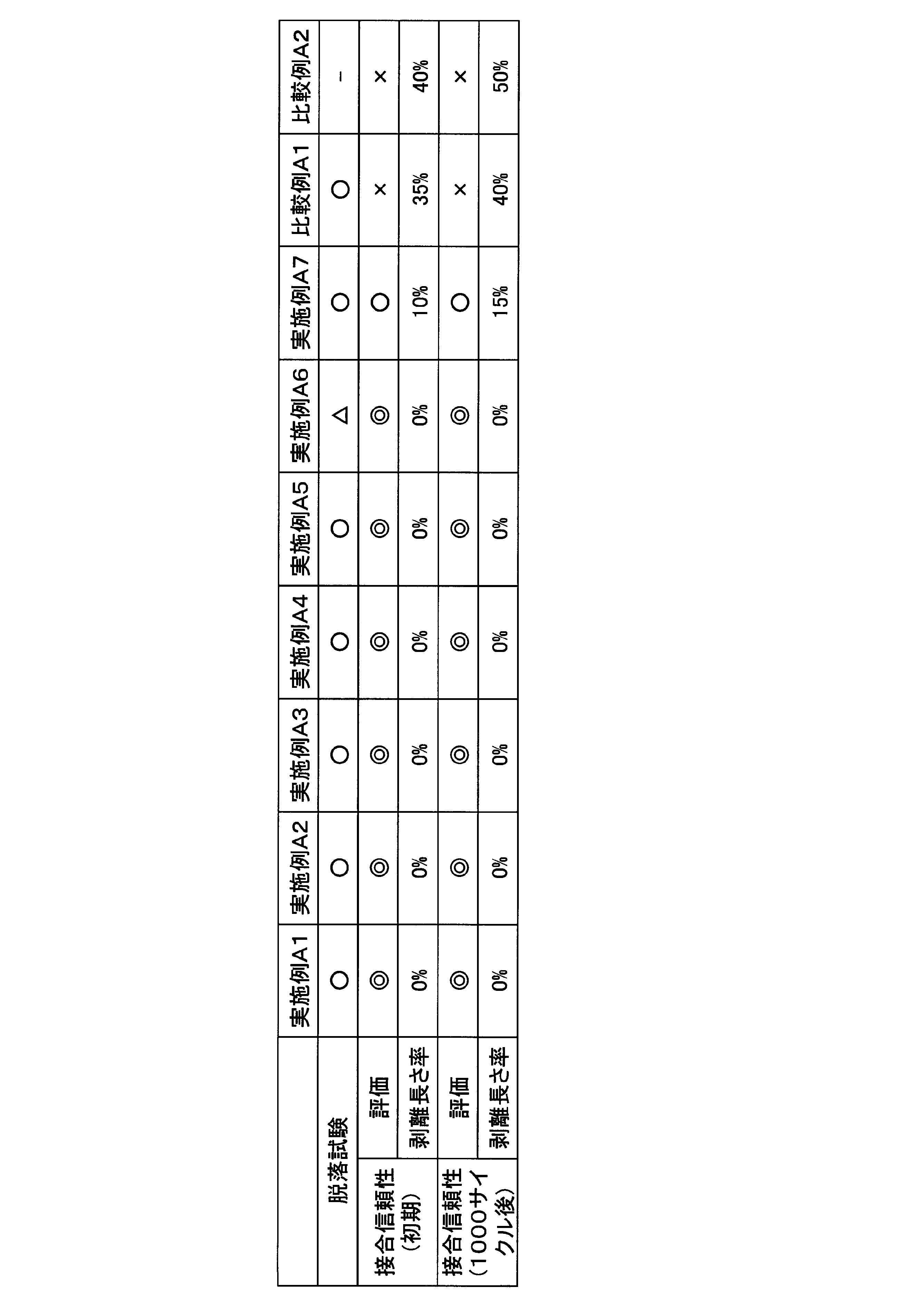
酸化物を含有していないフラックス成分侵入防止層が形成された比較例A1においては、脱落試験の評価は良好であったが、接合信頼性に劣ることが確認された。これは、フラックス成分侵入防止層が酸化物を有していないため、フラックス成分を分解できず、フラックス成分がセラミックス基板と金属層の接合面に侵入し、接合信頼性が低下したと推測される。
フラックス成分侵入防止層形成用ペーストを形成しなかった比較例A2においては、接合信頼性に劣ることが確認された。これは、フラックス成分がセラミックス基板と金属層の接合面に侵入し、接合信頼性が低下したと推測される。 In Comparative Example A1 in which the flux component intrusion prevention layer containing no oxide was formed, the evaluation of the dropout test was good, but it was confirmed that the bonding reliability was poor. This is presumed that since the flux component intrusion prevention layer does not have an oxide, the flux component cannot be decomposed, and the flux component penetrates into the joint surface between the ceramic substrate and the metal layer, thereby lowering the joining reliability. .
In Comparative Example A2 in which the flux component intrusion prevention layer forming paste was not formed, it was confirmed that the bonding reliability was inferior. This is presumed that the flux component entered the bonding surface between the ceramic substrate and the metal layer, and the bonding reliability was lowered.
これに対して、酸化物を含有したフラックス成分侵入防止層が形成された実施例A1-A7においては、接合信頼性が良好であることが確認された。フラックス成分であるKAlF4がフラックス成分侵入防止層と接触した際に分解されることから、フラックス成分がセラミックス基板と金属層の接合面に侵入することが防止され、接合信頼性が良好となったと推測される。
On the other hand, it was confirmed that in Examples A1-A7 in which the flux component penetration preventing layer containing oxide was formed, the bonding reliability was good. Since the flux component KAlF 4 is decomposed when it comes into contact with the flux component intrusion prevention layer, the flux component is prevented from entering the joining surface of the ceramic substrate and the metal layer, and the joining reliability is improved. Guessed.
さらに、フラックス成分侵入防止層における酸化物の含有量(乾燥後の酸化物量)が70.1%とされた実施例A6においては、樹脂の含有量が少ないため、脱落試験でフラックス成分侵入防止層の一部で脱落が認められた。
フラックス成分侵入防止層における酸化物の含有量(乾燥後の酸化物量)が4.5%とされた実施例A7においては、酸化物の含有量が少なかったため、実施例A1-A6と比較すると、若干の接合信頼性の低下が認められた。 Further, in Example A6 in which the content of oxide in the flux component intrusion prevention layer (the amount of oxide after drying) was 70.1%, the content of the resin was small, so the flux component intrusion prevention layer was used in the dropout test. A dropout was observed in part of
In Example A7 in which the content of oxide in the flux component intrusion prevention layer (the amount of oxide after drying) was 4.5%, the content of oxide was small, so compared with Examples A1-A6, A slight decrease in bonding reliability was observed.
以上の確認実験の結果、本発明によれば、ヒートシンクを接合した際に、セラミックス基板と金属層との接合信頼性の低下を防止できることが確認された。
さらに、フラックス成分侵入防止層における酸化物の含有量を望ましくは5体積%以上60体積%以下の範囲内とすることによって、フラックス成分侵入防止層の脱落を防止できるとともに、より確実に接合信頼性の低下を防止できることが確認された。 As a result of the above confirmation experiment, it was confirmed that according to the present invention, it is possible to prevent a decrease in the bonding reliability between the ceramic substrate and the metal layer when the heat sink is bonded.
Furthermore, by making the content of the oxide in the flux component intrusion prevention layer desirably in the range of 5% by volume or more and 60% by volume or less, the flux component intrusion prevention layer can be prevented from falling off and more reliably bonded reliability. It was confirmed that the decrease in the thickness could be prevented.
以下に、ペーストの効果を確認すべく実施した実験結果について説明する。
図3のフロー図に記載した手順で、表3に示す組成のフラックス成分侵入防止層用ペーストを製造した。有機物混合工程S01においては、遊星式撹拌装置(株式会社シンキー製「AR-250」(商品名))を用いて30分間の撹拌を実施し、樹脂を溶剤に溶解させた。
混錬工程S02においては、遊星式撹拌装置(株式会社シンキー製「AR-250」(商品名))を用いて5分間の撹拌を実施した。 Below, the experimental result implemented in order to confirm the effect of a paste is demonstrated.
The flux component intrusion prevention layer paste having the composition shown in Table 3 was manufactured by the procedure described in the flow chart of FIG. In the organic substance mixing step S01, stirring was performed for 30 minutes using a planetary stirrer (“AR-250” (trade name) manufactured by Sinky Corporation) to dissolve the resin in the solvent.
In the kneading step S02, stirring was performed for 5 minutes using a planetary stirring device (“AR-250” (trade name) manufactured by Shinky Corporation).
得られたフラックス成分侵入防止層用ペーストについて、温度25℃でのずり速度10s-1における粘度、及び、温度25℃でのずり速度100s-1における粘度について測定した。
ストレスレオメータ(TAインスツルメント株式会社製「AR-1000」(商品名))に、測定治具としてコーン(4°、直径40mm)を用い、このコーンを回転させてフラックス成分侵入防止層用ペーストに対して所定のずり速度を与え、3分後の粘度を測定した。測定結果を表4に示す。 The obtained flux component intrusion prevention layer paste was measured for a viscosity at a shear rate of 10 s −1 at a temperature of 25 ° C. and a viscosity at a shear rate of 100 s −1 at a temperature of 25 ° C.
A stress rheometer ("AR-1000" (trade name) manufactured by TA Instruments Co., Ltd.) was used with a cone (4 °, 40 mm in diameter) as a measuring jig, and this cone was rotated to paste the flux component intrusion prevention layer paste. Was given a predetermined shear rate, and the viscosity after 3 minutes was measured. Table 4 shows the measurement results.
これらのフラックス成分侵入防止層用ペーストを用いて、上述の実施形態で開示されたパワーモジュール用基板のフラックス成分侵入防止層を形成した。セラミックス基板は30mm×20mm×0.635mmであり、回路層は13mm×10mm×0.6mmであり、金属層は13mm×10mm×1.6mmであり、ヒートシンクの天板部は50mm×50mm×7mmであった。
ディスペンサー(武蔵エンジニアリング株式会社製「SuperΣ X-V2」(商品名))に内径0.26mmのニードルを付け、塗布圧0.20kPaにて、上述のパワーモジュール用基板のセラミックス基板と金属層との接合面の周縁にフラックス成分侵入防止層用ペーストを塗布した。塗布後、ホットプレート上で80℃、5分間の乾燥処理を実施した。 Using the flux component intrusion prevention layer paste, the flux component intrusion prevention layer of the power module substrate disclosed in the above embodiment was formed. The ceramic substrate is 30 mm x 20 mm x 0.635 mm, the circuit layer is 13 mm x 10 mm x 0.6 mm, the metal layer is 13 mm x 10 mm x 1.6 mm, and the top plate of the heat sink is 50 mm x 50 mm x 7 mm Met.
Attach a needle with an inner diameter of 0.26 mm to a dispenser ("SuperΣ X-V2" (trade name) manufactured by Musashi Engineering Co., Ltd.) and apply the ceramic substrate and metal layer of the power module substrate described above at a coating pressure of 0.20 kPa. A flux component intrusion prevention layer paste was applied to the periphery of the joint surface. After the application, a drying treatment was performed on a hot plate at 80 ° C. for 5 minutes.
まず、フィレット形状を評価した。
フラックス成分侵入防止層を光学顕微鏡にて観察し、フラックス成分侵入防止層用ペーストの抜けや隙間の有無を確認した。抜け若しくは隙間が確認されないものを○、長さ3mm以下の抜け若しくは隙間が1箇所のみ確認されたものを△、長さが3mm超の抜け若しくは隙間が確認された場合、若しくは、長さが3mm以下の抜け若しくは隙間が2箇所以上確認されたものを×と評価した。長さ3mm以下の抜け若しくは隙間が1箇所の場合には実用上問題ないレベルである。 First, the fillet shape was evaluated.
The flux component intrusion prevention layer was observed with an optical microscope, and the presence or absence of the flux component intrusion prevention layer paste was confirmed. ◯ if no omission or gap is confirmed, △ if omission of 3 mm or less or gap is confirmed only in one place, Δ if omission or gap more than 3 mm in length is confirmed, or length is 3 mm The case where two or more of the following gaps or gaps were confirmed was evaluated as x. When there is a gap or gap of 3 mm or less in length, there is no practical problem.
次に、上述のパワーモジュール用基板にヒートシンクの天板部のみを、ノコロックろう付けによって接合して、ヒートシンク付パワーモジュール用基板とした。
まず、得られたヒートシンク付パワーモジュール用基板に対して、セラミックス基板と金属層との接合面を超音波探傷装置(株式会社日立エンジニアリング・アンド・サービス製「Fine SAT FS-200」(商品名))によって観察し、剥離の有無によって、初期の接合信頼性を評価した。
次に、このヒートシンク付パワーモジュール用基板に対して、-40℃~125℃の冷熱サイクルを1000サイクル行った。セラミックス基板と金属層との接合面を超音波探傷装置(株式会社日立エンジニアリング・アンド・サービス製「Fine SAT FS-200」(商品名))によって観察し、剥離の有無によって、冷熱サイクル後の接合信頼性を評価した。
ノコロック接合時の剥離は金属層の外周部から発生し、超音波探傷像においてこの剥離部は接合部内の白色部として示されることから、金属層外周部に沿った白色部の長さを測定し剥離長さとした。剥離が無い場合を○、長さに対する剥離長さの割合(剥離長さ率)が30%以下の場合を△、剥離長さ率が30%を超える場合を×と評価した。評価結果と剥離長さ率を表4に示す。 Next, only the top plate portion of the heat sink was joined to the above-described power module substrate by sawlock brazing to obtain a power module substrate with a heat sink.
First, an ultrasonic flaw detector ("Fine SAT FS-200" (trade name) manufactured by Hitachi Engineering & Service Co., Ltd.) is used to bond the bonding surface between the ceramic substrate and the metal layer to the obtained power module substrate with a heat sink. ) And the initial bonding reliability was evaluated by the presence or absence of peeling.
Next, 1000 cycles of a cooling cycle of −40 ° C. to 125 ° C. were performed on the power module substrate with a heat sink. The bonding surface between the ceramic substrate and the metal layer is observed with an ultrasonic flaw detector (“Fine SAT FS-200” (trade name) manufactured by Hitachi Engineering & Service Co., Ltd.). Reliability was evaluated.
Peeling at the time of noco-lock joining occurs from the outer periphery of the metal layer, and in the ultrasonic flaw detection image, this peeling part is shown as a white part in the joined part, so the length of the white part along the outer part of the metal layer is measured. The peel length was used. The case where there was no peeling was evaluated as ◯, the case where the ratio of the peeling length to the length (peeling length ratio) was 30% or less, Δ, and the case where the peeling length ratio exceeded 30% was evaluated as x. Table 4 shows the evaluation results and the peel length ratio.
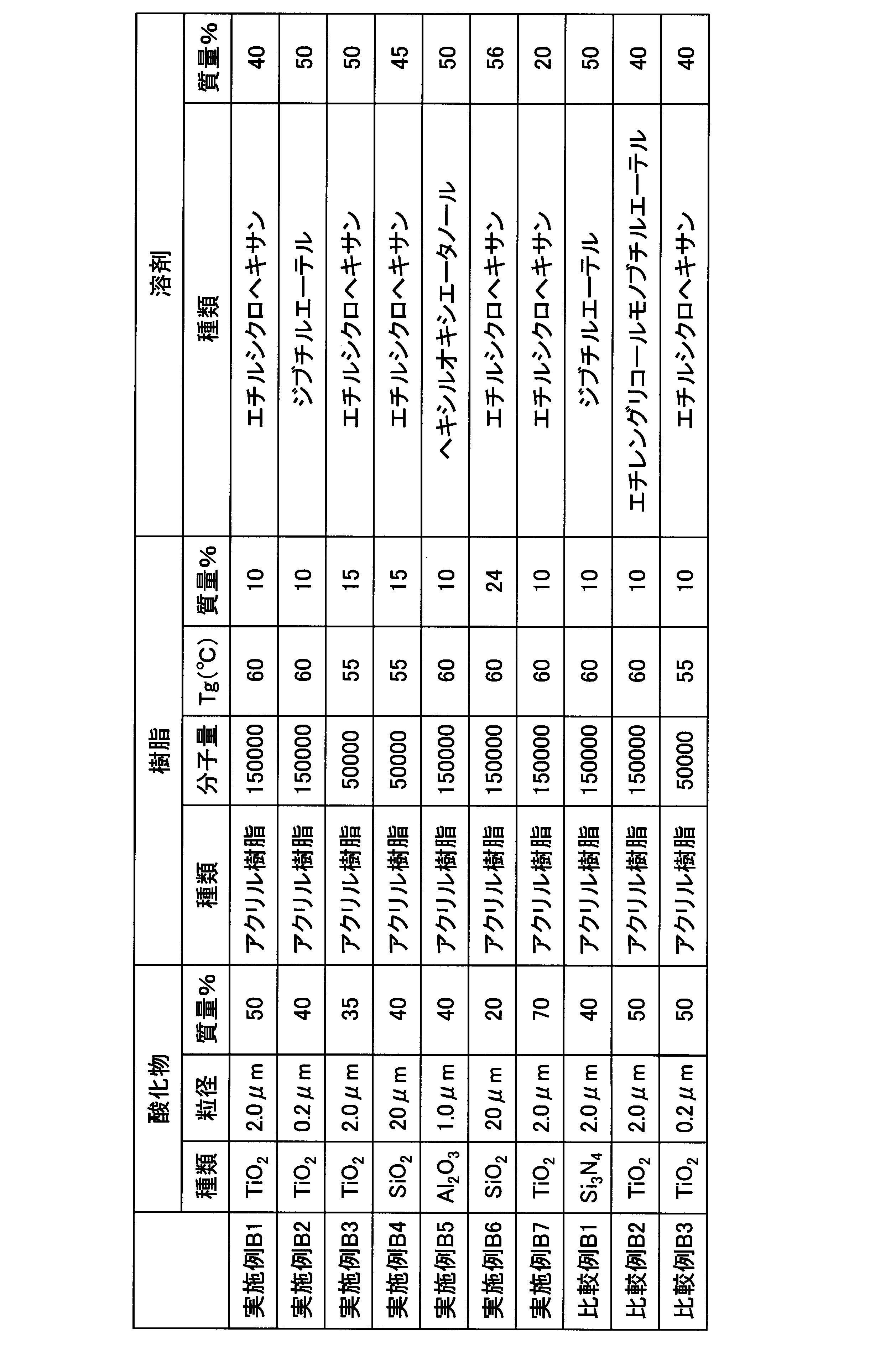
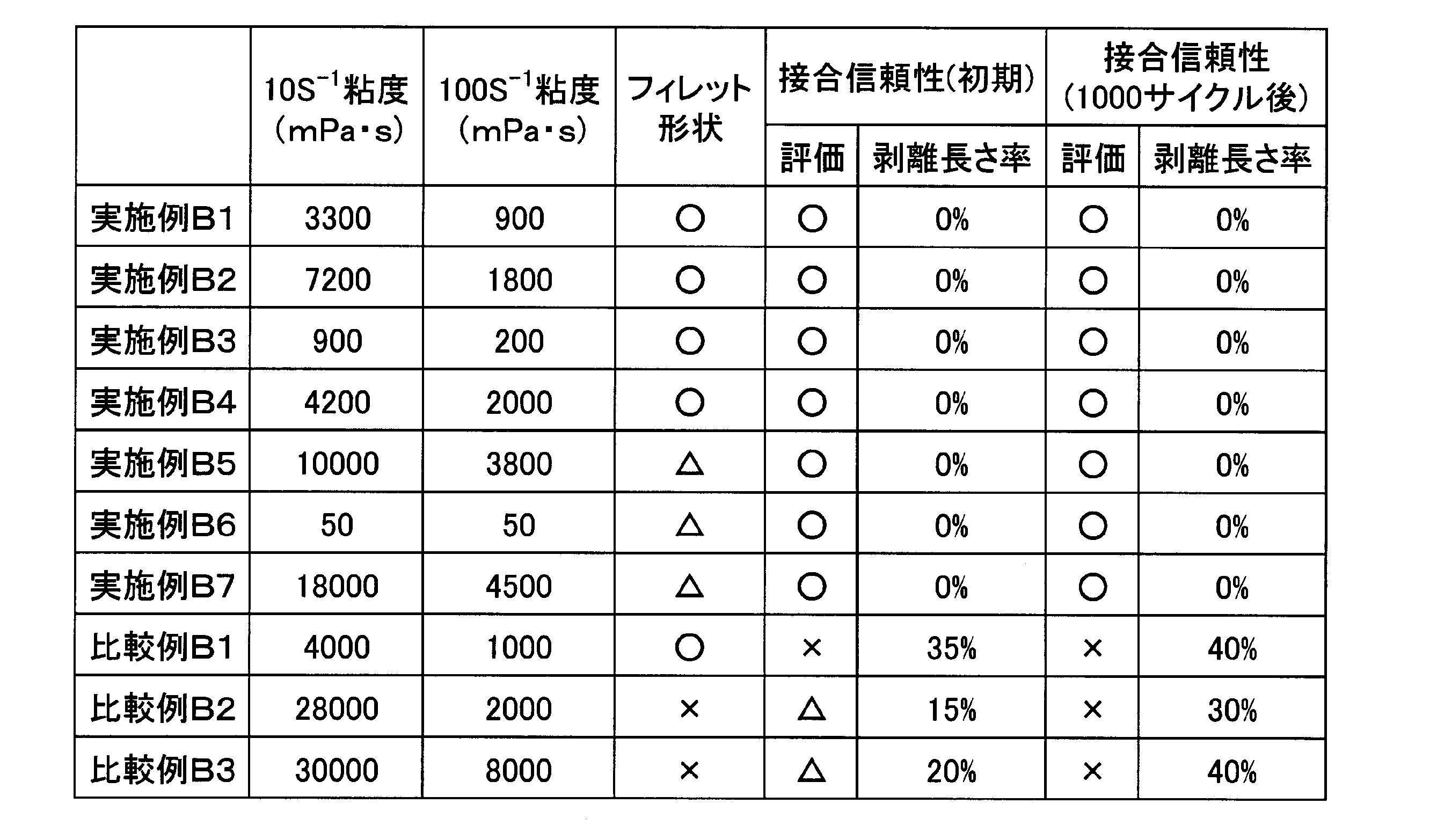
温度25℃でのずり速度10s-1における粘度が、10mPa・s以上20000mPa・s以下の範囲内とされ、温度25℃でのずり速度100s-1における粘度が、10mPa・s以上5000mPa・s以下の範囲内とされた実施例B1-B7においては、初期の接合信頼性及び冷熱サイクル後の接合信頼性が良好であることが確認された。これは、フラックス成分がセラミックス基板と金属層との接合面に侵入しなかったためと推測される。
さらに、温度25℃でのずり速度10s-1における粘度を、100mPa・s以上10000mPa・s以下の範囲内とされ、かつ、温度25℃でのずり速度100s-1における粘度を、50mPa・s以上2500mPa・s以下の範囲内とされた実施例B1-B4においては、塗布後のフィレット形状が良好であることが確認された。 The viscosity at a shear rate of 10 s −1 at a temperature of 25 ° C. is in the range of 10 mPa · s to 20000 mPa · s, and the viscosity at a shear rate of 100 s −1 at a temperature of 25 ° C. is from 10 mPa · s to 5000 mPa · s. In Examples B1 to B7, the initial bonding reliability and the bonding reliability after the thermal cycle were confirmed to be good. This is presumably because the flux component did not enter the bonding surface between the ceramic substrate and the metal layer.
Further, the viscosity at a shear rate of 10 s −1 at a temperature of 25 ° C. is in the range of 100 mPa · s to 10000 mPa · s, and the viscosity at a shear rate of 100 s −1 at a temperature of 25 ° C. is 50 mPa · s or more. In Examples B1 to B4, which were within the range of 2500 mPa · s or less, it was confirmed that the fillet shape after application was good.
これに対して、比較例B1-B3においては、接合信頼性が低いことが確認された。
フラックス成分を分解する酸化物を含有しない比較例B1においては、温度25℃でのずり速度10s-1における粘度が10mPa・s以上10000mPa・s以下の範囲内、温度25℃でのずり速度100s-1における粘度が50mPa・s以上2500mPa・s以下の範囲内とされていることから、塗布形状は良好である。しかしながら、フラックス成分を分解する酸化物を有していないため、フラックス成分を分解できず、フラックス成分がセラミックス基板と金属層の接合面に侵入し、接合信頼性が低下したと推測される。 On the other hand, in Comparative Examples B1-B3, it was confirmed that the bonding reliability was low.
In Comparative Example B1 that does not contain an oxide that decomposes the flux component, the viscosity at a shear rate of 10 s −1 at a temperature of 25 ° C. is in the range of 10 mPa · s to 10,000 mPa · s, and the shear rate at a temperature of 25 ° C. is 100 s −. Since the viscosity at 1 is in the range of 50 mPa · s to 2500 mPa · s, the coating shape is good. However, since the oxide does not have an oxide that decomposes the flux component, the flux component cannot be decomposed, and the flux component enters the bonding surface between the ceramic substrate and the metal layer, and it is assumed that the bonding reliability is lowered.
温度25℃でのずり速度10s-1における粘度が28000mPa・sとされた比較例B2においては、塗布後のペーストがダレないため、塗布形状が不良となった。これにより、フラックス成分がセラミックス基板と金属層の接合面に侵入し、接合信頼性が低下したと推測される。
温度25℃でのずり速度100s-1における粘度が8000mPa・sとされた比較例B3においては、ペーストの塗布を良好に行うことができず、フィレット形状が不良となった。これにより、フラックス成分がセラミックス基板と金属層の接合面に侵入し、接合信頼性が低下したと推測される。 In Comparative Example B2 in which the viscosity at a shear rate of 10 s −1 at a temperature of 25 ° C. was 28000 mPa · s, the applied shape was poor because the paste after application did not sag. Thereby, it is presumed that the flux component entered the bonding surface between the ceramic substrate and the metal layer, and the bonding reliability was lowered.
In Comparative Example B3 in which the viscosity at a shear rate of 100 s −1 at a temperature of 25 ° C. was 8000 mPa · s, the paste could not be applied satisfactorily and the fillet shape was poor. Thereby, it is presumed that the flux component entered the bonding surface between the ceramic substrate and the metal layer, and the bonding reliability was lowered.
以上の確認実験の結果、本発明によれば、フラックス成分侵入防止層を良好に形成できるフラックス成分侵入防止層形成用ペーストを提供できることが確認された。
As a result of the above confirmation experiment, it was confirmed that according to the present invention, it is possible to provide a paste for forming a flux component intrusion prevention layer that can satisfactorily form a flux component intrusion prevention layer.
本発明によれば、フラックスを用いて被接合材を接合する場合であっても、フラックス侵入防止層を確実に付着させておくことができ、絶縁層と金属板との接合信頼性が低下することを抑制できるから、産業上の利用が可能である。
According to the present invention, even when a material to be bonded is bonded using a flux, the flux intrusion prevention layer can be reliably adhered, and the bonding reliability between the insulating layer and the metal plate is lowered. Since this can be suppressed, industrial use is possible.
10 パワーモジュール用基板
11 セラミックス基板(絶縁層)
13 金属層
40 ヒートシンク
51 フラックス成分侵入防止層 10Power Module Substrate 11 Ceramic Substrate (Insulating Layer)
13Metal layer 40 Heat sink 51 Flux component intrusion prevention layer
11 セラミックス基板(絶縁層)
13 金属層
40 ヒートシンク
51 フラックス成分侵入防止層 10
13
Claims (11)
- 絶縁層の一方の面に回路層が形成され、前記絶縁層の他方の面に金属層が形成されており、この金属層の他方の面にフラックスを使用して被接合体が接合されるパワーモジュール用基板であって、
前記絶縁層と前記金属層との接合面の周縁部には、酸化物と樹脂とを含有するフラックス成分侵入防止層が形成されていることを特徴とするパワーモジュール用基板。 A circuit layer is formed on one surface of the insulating layer, a metal layer is formed on the other surface of the insulating layer, and the power to which the object to be bonded is bonded to the other surface of the metal layer using a flux A module substrate,
A power module substrate, wherein a flux component intrusion prevention layer containing an oxide and a resin is formed at a peripheral portion of a joint surface between the insulating layer and the metal layer. - 前記フラックス成分侵入防止層は、前記酸化物を5体積%以上60体積%以下の範囲内で含み、残部が前記樹脂とされていることを特徴とする請求項1に記載のパワーモジュール用基板。 2. The power module substrate according to claim 1, wherein the flux component intrusion prevention layer includes the oxide in a range of 5% by volume to 60% by volume, and the remainder is the resin.
- 前記酸化物が、TiO2、SiO2、Al2O3のうちのいずれか1種又は2種以上とされていることを特徴とする請求項1記載のパワーモジュール用基板。 2. The power module substrate according to claim 1, wherein the oxide is one or more of TiO 2 , SiO 2 , and Al 2 O 3 .
- 請求項1記載のパワーモジュール用基板と、前記パワーモジュール用基板の前記金属層にフラックスを用いて接合されたヒートシンクとを備えたことを特徴とするヒートシンク付パワーモジュール用基板。 A power module substrate with a heat sink, comprising: the power module substrate according to claim 1; and a heat sink joined to the metal layer of the power module substrate with a flux.
- 請求項1記載のパワーモジュール用基板と、前記回路層上に配設された電子部品とを備えたことを特徴とするパワーモジュール。 A power module comprising the power module substrate according to claim 1 and an electronic component disposed on the circuit layer.
- フラックス成分侵入防止層を形成するためのフラックス成分侵入防止層形成用ペーストであって、
フラックス成分を分解する酸化物と、樹脂と、溶剤とを含有し、
温度25℃でのずり速度10s-1における粘度が、10mPa・s以上20000mPa・s以下の範囲内とされ、
温度25℃でのずり速度100s-1における粘度が、10mPa・s以上5000mPa・s以下の範囲内とされていることを特徴とするフラックス成分侵入防止層形成用ペースト。 A flux component intrusion prevention layer forming paste for forming a flux component intrusion prevention layer,
Contains an oxide that decomposes the flux component, a resin, and a solvent,
The viscosity at a shear rate of 10 s −1 at a temperature of 25 ° C. is in the range of 10 mPa · s to 20000 mPa · s,
A paste for forming a flux component intrusion prevention layer, characterized in that the viscosity at a shear rate of 100 s -1 at a temperature of 25 ° C is in the range of 10 mPa · s to 5000 mPa · s. - 前記酸化物が、TiO2、SiO2、Al2O3のうちのいずれか1種又は2種以上とされていることを特徴とする請求項6に記載のフラックス成分侵入防止層形成用ペースト。 The flux component intrusion prevention layer forming paste according to claim 6, wherein the oxide is one or more of TiO 2 , SiO 2 , and Al 2 O 3 .
- 前記酸化物の含有量が10質量%以上80質量%以下、前記樹脂の含有量が5質量%以上30質量%以下、残部が溶剤とされていることを特徴とする請求項6記載のフラックス成分侵入防止層形成用ペースト。 The flux component according to claim 6, wherein the oxide content is 10% by mass or more and 80% by mass or less, the resin content is 5% by mass or more and 30% by mass or less, and the balance is a solvent. Paste for forming an intrusion prevention layer.
- 絶縁層の一方の面に回路層が形成され、前記絶縁層の他方の面に金属層が形成されており、この金属層の他方の面にフラックスを使用して被接合体が接合されるパワーモジュール用基板の製造方法であって、
請求項6から請求項8のいずれか一項に記載のフラックス成分侵入防止層形成用ペーストを使用して、前記絶縁層と前記金属層との接合面にフラックス成分が前記接合面に侵入することを抑制するフラックス成分侵入防止層を形成する工程を有する、パワーモジュール用基板の製造方法。 A circuit layer is formed on one surface of the insulating layer, a metal layer is formed on the other surface of the insulating layer, and the power to which the object to be bonded is bonded to the other surface of the metal layer using a flux A method of manufacturing a module substrate,
Using the flux component intrusion prevention layer forming paste according to any one of claims 6 to 8, a flux component penetrates into the joint surface between the insulating layer and the metal layer. The manufacturing method of the board | substrate for power modules which has the process of forming the flux component penetration | invasion prevention layer which suppresses. - 請求項9記載のパワーモジュール用基板の製造方法において、前記金属層にフラックスを用いたろう付けによってヒートシンクを接合する工程をさらに具備することを特徴とするヒートシンク付パワーモジュール用基板の製造方法。 10. The method for manufacturing a power module substrate with a heat sink according to claim 9, further comprising the step of joining a heat sink by brazing using a flux to the metal layer.
- 請求項10記載のヒートシンク付パワーモジュール用基板の製造方法において、前記回路層に電子部品を配設する工程をさらに有する、ヒートシンク付パワーモジュールの製造方法。 The method for manufacturing a power module with a heat sink according to claim 10, further comprising a step of arranging an electronic component on the circuit layer.
Priority Applications (4)
| Application Number | Priority Date | Filing Date | Title |
|---|---|---|---|
| CN201280060840.6A CN103988297B (en) | 2011-12-12 | 2012-12-11 | Power module and its manufacturing method |
| EP12857715.2A EP2793258A4 (en) | 2011-12-12 | 2012-12-11 | Power module substrate, substrate for power module with heat sink, power module, paste for forming flux component penetration prevention layer, and bonding method for article to be bonded |
| KR1020147015192A KR101983420B1 (en) | 2011-12-12 | 2012-12-11 | Power module substrate, substrate for power module with heat sink, power module, paste for forming flux component penetration prevention layer, and bonding method for article to be bonded |
| US14/363,437 US20140318831A1 (en) | 2011-12-12 | 2012-12-11 | Power module substrate, power module substrate with heat sink, power module, paste for forming flux component intrusion-preventing layer and method for bonding bonded body |
Applications Claiming Priority (4)
| Application Number | Priority Date | Filing Date | Title |
|---|---|---|---|
| JP2011271146A JP5344025B2 (en) | 2011-12-12 | 2011-12-12 | Flux component intrusion prevention layer forming paste and joined body joining method |
| JP2011-271146 | 2011-12-12 | ||
| JP2011-271081 | 2011-12-12 | ||
| JP2011271081A JP5344024B2 (en) | 2011-12-12 | 2011-12-12 | Power module substrate, power module substrate with heat sink, and power module |
Publications (1)
| Publication Number | Publication Date |
|---|---|
| WO2013089099A1 true WO2013089099A1 (en) | 2013-06-20 |
Family
ID=48612546
Family Applications (1)
| Application Number | Title | Priority Date | Filing Date |
|---|---|---|---|
| PCT/JP2012/082066 WO2013089099A1 (en) | 2011-12-12 | 2012-12-11 | Power module substrate, substrate for power module with heat sink, power module, paste for forming flux component penetration prevention layer, and bonding method for article to be bonded |
Country Status (5)
| Country | Link |
|---|---|
| US (1) | US20140318831A1 (en) |
| EP (1) | EP2793258A4 (en) |
| KR (1) | KR101983420B1 (en) |
| CN (1) | CN103988297B (en) |
| WO (1) | WO2013089099A1 (en) |
Families Citing this family (5)
| Publication number | Priority date | Publication date | Assignee | Title |
|---|---|---|---|---|
| JP5542765B2 (en) * | 2011-09-26 | 2014-07-09 | 日立オートモティブシステムズ株式会社 | Power module |
| US10016956B2 (en) * | 2013-09-30 | 2018-07-10 | Mitsubishi Materials Corporation | Cu/ceramic bonded body, method for manufacturing Cu/ceramic bonded body, and power module substrate |
| JP6272512B2 (en) * | 2015-01-26 | 2018-01-31 | 三菱電機株式会社 | Semiconductor device and manufacturing method of semiconductor device |
| US10707143B2 (en) * | 2016-05-30 | 2020-07-07 | Industrial Technology Research Institute | Plug-in type power module and subsystem thereof |
| DE102017205813A1 (en) * | 2017-04-05 | 2018-10-11 | Mahle International Gmbh | A method of manufacturing a cooling device, a cooling device and a cooling arrangement |
Citations (10)
| Publication number | Priority date | Publication date | Assignee | Title |
|---|---|---|---|---|
| JPS6462266A (en) * | 1987-08-29 | 1989-03-08 | Tokuriki Honten Kk | Stop-off agent for brazing |
| JP2001012887A (en) | 1999-06-30 | 2001-01-19 | Denso Corp | Heat exchanger and brazing method thereof |
| JP2007194256A (en) | 2006-01-17 | 2007-08-02 | Mitsubishi Materials Corp | Producing process of substrate for power module |
| JP2009105166A (en) | 2007-10-22 | 2009-05-14 | Toyota Motor Corp | Cooling device for semiconductor module |
| JP2010047717A (en) * | 2008-08-25 | 2010-03-04 | Taoka Chem Co Ltd | One-part type liquid epoxy resin composition |
| JP2010138955A (en) | 2008-12-10 | 2010-06-24 | Panasonic Corp | Connection structure of aluminum tube, connection method therefor, and heat exchanger |
| JP2011079957A (en) * | 2009-10-07 | 2011-04-21 | Taoka Chem Co Ltd | One-pack liquid curable composition for relay having excellent noise-reducing property |
| JP2011210745A (en) * | 2010-03-26 | 2011-10-20 | Mitsubishi Materials Corp | Substrate for power module, and method of manufacturing the same |
| JP2011228563A (en) | 2010-04-22 | 2011-11-10 | Showa Denko Kk | Method of brazing insulating laminate material |
| JP2011240374A (en) * | 2010-05-19 | 2011-12-01 | Showa Denko Kk | Brazing method for insulation laminated material |
Family Cites Families (33)
| Publication number | Priority date | Publication date | Assignee | Title |
|---|---|---|---|---|
| GB9312328D0 (en) * | 1993-06-15 | 1993-07-28 | Lexor Technology Limited | A method of brazing |
| DE69535775D1 (en) * | 1994-10-07 | 2008-08-07 | Hitachi Ltd | Semiconductor arrangement with a plurality of semiconductor elements |
| CA2255441C (en) * | 1997-12-08 | 2003-08-05 | Hiroki Sekiya | Package for semiconductor power device and method for assembling the same |
| US6265776B1 (en) * | 1998-04-27 | 2001-07-24 | Fry's Metals, Inc. | Flip chip with integrated flux and underfill |
| JP2001269772A (en) * | 2000-03-27 | 2001-10-02 | Showa Denko Kk | Method for joining metal and metal and joined product |
| US6545869B2 (en) * | 2001-01-17 | 2003-04-08 | International Business Machines Corporation | Adjusting fillet geometry to couple a heat spreader to a chip carrier |
| TWI234210B (en) * | 2002-12-03 | 2005-06-11 | Sanyo Electric Co | Semiconductor module and manufacturing method thereof as well as wiring member of thin sheet |
| EP1465250A1 (en) * | 2003-04-02 | 2004-10-06 | Abb Research Ltd. | Insulated power semiconductor module with reduced partial discharge and manufacturing method |
| WO2005093829A1 (en) * | 2004-03-16 | 2005-10-06 | Infineon Technologies Ag | Semiconductor package having an interfacial adhesive layer |
| CN100446205C (en) * | 2004-03-29 | 2008-12-24 | 日本电气株式会社 | Semiconductor device and process for manufacturing the same |
| US7495887B2 (en) * | 2004-12-21 | 2009-02-24 | E.I. Du Pont De Nemours And Company | Capacitive devices, organic dielectric laminates, and printed wiring boards incorporating such devices, and methods of making thereof |
| JP4621531B2 (en) * | 2005-04-06 | 2011-01-26 | 株式会社豊田自動織機 | Heat dissipation device |
| US20060272747A1 (en) * | 2005-06-03 | 2006-12-07 | Renyi Wang | Fluxing compositions |
| JP2007165445A (en) * | 2005-12-12 | 2007-06-28 | Matsushita Electric Ind Co Ltd | Power amplifier module |
| US8004075B2 (en) * | 2006-04-25 | 2011-08-23 | Hitachi, Ltd. | Semiconductor power module including epoxy resin coating |
| JP4525636B2 (en) * | 2006-06-09 | 2010-08-18 | 株式会社日立製作所 | Power module |
| JP4735446B2 (en) * | 2006-07-04 | 2011-07-27 | 三菱電機株式会社 | Semiconductor device |
| WO2008075409A1 (en) * | 2006-12-19 | 2008-06-26 | Kabushiki Kaisha Toyota Jidoshokki | Base for power module, method for producing base for power module and power module |
| JP4895994B2 (en) * | 2006-12-28 | 2012-03-14 | 株式会社日立製作所 | Joining method and joining material using metal particles |
| KR101610973B1 (en) * | 2008-03-17 | 2016-04-08 | 미쓰비시 마테리알 가부시키가이샤 | Substrate for power module with heat sink and method for producing the same, power module with heat sink, and substrate for power module |
| KR20110033117A (en) * | 2008-06-06 | 2011-03-30 | 미쓰비시 마테리알 가부시키가이샤 | Substrate for power module, power module, and method for producing substrate for power module |
| JP5423076B2 (en) * | 2008-06-06 | 2014-02-19 | 三菱マテリアル株式会社 | Power module substrate, power module, and method of manufacturing power module substrate |
| US8472193B2 (en) * | 2008-07-04 | 2013-06-25 | Kabushiki Kaisha Toyota Jidoshokki | Semiconductor device |
| DE102008049850A1 (en) * | 2008-10-01 | 2010-04-08 | Tesa Se | Thermally conductive pressure-sensitive adhesive |
| CN101781443B (en) * | 2009-01-20 | 2012-03-28 | 财团法人工业技术研究院 | Thermosetting solder masking film composite |
| JP5120284B2 (en) * | 2009-02-04 | 2013-01-16 | 株式会社豊田自動織機 | Semiconductor device |
| JP5296590B2 (en) * | 2009-03-30 | 2013-09-25 | 新光電気工業株式会社 | Manufacturing method of semiconductor package |
| EP2477217B1 (en) * | 2009-09-09 | 2019-05-08 | Mitsubishi Materials Corporation | Method for producing substrate for power module with heat sink, substrate for power module with heat sink, and power module |
| DE102010000942B4 (en) * | 2010-01-15 | 2022-08-25 | Infineon Technologies Ag | Process for manufacturing a power semiconductor module |
| JP5278354B2 (en) * | 2010-03-03 | 2013-09-04 | 三菱マテリアル株式会社 | Power module substrate, power module substrate manufacturing method, power module substrate with heat sink, and power module |
| JP5212417B2 (en) * | 2010-04-12 | 2013-06-19 | 三菱電機株式会社 | Power semiconductor module |
| CN102651349B (en) * | 2011-02-25 | 2016-07-06 | 三菱综合材料株式会社 | Power module substrate and method for making, this substrate carrying radiator and power model |
| JP5853727B2 (en) * | 2012-01-30 | 2016-02-09 | 三菱マテリアル株式会社 | Manufacturing method of power module substrate with heat sink |
-
2012
- 2012-12-11 KR KR1020147015192A patent/KR101983420B1/en active IP Right Grant
- 2012-12-11 CN CN201280060840.6A patent/CN103988297B/en active Active
- 2012-12-11 EP EP12857715.2A patent/EP2793258A4/en not_active Withdrawn
- 2012-12-11 WO PCT/JP2012/082066 patent/WO2013089099A1/en active Application Filing
- 2012-12-11 US US14/363,437 patent/US20140318831A1/en not_active Abandoned
Patent Citations (10)
| Publication number | Priority date | Publication date | Assignee | Title |
|---|---|---|---|---|
| JPS6462266A (en) * | 1987-08-29 | 1989-03-08 | Tokuriki Honten Kk | Stop-off agent for brazing |
| JP2001012887A (en) | 1999-06-30 | 2001-01-19 | Denso Corp | Heat exchanger and brazing method thereof |
| JP2007194256A (en) | 2006-01-17 | 2007-08-02 | Mitsubishi Materials Corp | Producing process of substrate for power module |
| JP2009105166A (en) | 2007-10-22 | 2009-05-14 | Toyota Motor Corp | Cooling device for semiconductor module |
| JP2010047717A (en) * | 2008-08-25 | 2010-03-04 | Taoka Chem Co Ltd | One-part type liquid epoxy resin composition |
| JP2010138955A (en) | 2008-12-10 | 2010-06-24 | Panasonic Corp | Connection structure of aluminum tube, connection method therefor, and heat exchanger |
| JP2011079957A (en) * | 2009-10-07 | 2011-04-21 | Taoka Chem Co Ltd | One-pack liquid curable composition for relay having excellent noise-reducing property |
| JP2011210745A (en) * | 2010-03-26 | 2011-10-20 | Mitsubishi Materials Corp | Substrate for power module, and method of manufacturing the same |
| JP2011228563A (en) | 2010-04-22 | 2011-11-10 | Showa Denko Kk | Method of brazing insulating laminate material |
| JP2011240374A (en) * | 2010-05-19 | 2011-12-01 | Showa Denko Kk | Brazing method for insulation laminated material |
Non-Patent Citations (1)
| Title |
|---|
| See also references of EP2793258A4 |
Also Published As
| Publication number | Publication date |
|---|---|
| KR101983420B1 (en) | 2019-05-29 |
| EP2793258A4 (en) | 2015-11-11 |
| EP2793258A1 (en) | 2014-10-22 |
| US20140318831A1 (en) | 2014-10-30 |
| CN103988297B (en) | 2018-11-23 |
| CN103988297A (en) | 2014-08-13 |
| KR20140110850A (en) | 2014-09-17 |
Similar Documents
| Publication | Publication Date | Title |
|---|---|---|
| JP5757359B2 (en) | Cu / ceramic bonded body, Cu / ceramic bonded body manufacturing method, and power module substrate | |
| KR102459745B1 (en) | Copper/ceramic bonded body, insulated circuit board, and copper/ceramic bonded body manufacturing method, insulated circuit board manufacturing method | |
| TWI729158B (en) | Cupper/ceramic bonded body and insulating circuit substrate | |
| KR102154889B1 (en) | Method for manufacturing assembly and method for manufacturing power-module substrate | |
| WO2014148420A1 (en) | Method for manufacturing power-module substrate | |
| KR102131484B1 (en) | Assembly and power-module substrate | |
| TWI746807B (en) | Copper/ceramic bonded body, insulating circuit substrate, method of manufacturing copper/ceramic bonded body and method of manufacturing insulating circuit substrate | |
| WO2013115359A1 (en) | Substrate for power modules, substrate with heat sink for power modules, power module, method for producing substrate for power modules, and paste for bonding copper member | |
| WO2013089099A1 (en) | Power module substrate, substrate for power module with heat sink, power module, paste for forming flux component penetration prevention layer, and bonding method for article to be bonded | |
| WO2014088025A1 (en) | Substrate for power modules, substrate with heat sink for power modules, power module, method for producing substrate for power modules, paste for copper plate bonding, and method for producing bonded body | |
| KR102330134B1 (en) | Process for producing united object and process for producing substrate for power module | |
| JP2017183716A (en) | Manufacturing method of insulation circuit board with heat sink, and insulation circuit board with heat sink | |
| CN108780784B (en) | Metal member with Ag-based layer, insulated circuit board with Ag-based layer, semiconductor device, insulated circuit board with heat sink, and method for manufacturing metal member with Ag-based layer | |
| TWI711141B (en) | Semiconductor device | |
| TWI813593B (en) | Bonded body and insulated circuit substrate | |
| WO2018168476A1 (en) | Method for producing bonded body, method for producing insulated circuit board, and method for producing insulated circuit board with heatsink | |
| JP5344024B2 (en) | Power module substrate, power module substrate with heat sink, and power module | |
| JP5344025B2 (en) | Flux component intrusion prevention layer forming paste and joined body joining method | |
| JP7243182B2 (en) | Insulated circuit board manufacturing method and its insulated circuit board |
Legal Events
| Date | Code | Title | Description |
|---|---|---|---|
| 121 | Ep: the epo has been informed by wipo that ep was designated in this application |
Ref document number: 12857715 Country of ref document: EP Kind code of ref document: A1 |
|
| ENP | Entry into the national phase |
Ref document number: 20147015192 Country of ref document: KR Kind code of ref document: A |
|
| WWE | Wipo information: entry into national phase |
Ref document number: 14363437 Country of ref document: US |
|
| NENP | Non-entry into the national phase |
Ref country code: DE |